EP4267889B1 - Maschine für pharmazeutische oder biotechnologische verfahren, zusammenbau und verfahren zur realisierung der maschine - Google Patents
Maschine für pharmazeutische oder biotechnologische verfahren, zusammenbau und verfahren zur realisierung der maschine Download PDFInfo
- Publication number
- EP4267889B1 EP4267889B1 EP22801225.8A EP22801225A EP4267889B1 EP 4267889 B1 EP4267889 B1 EP 4267889B1 EP 22801225 A EP22801225 A EP 22801225A EP 4267889 B1 EP4267889 B1 EP 4267889B1
- Authority
- EP
- European Patent Office
- Prior art keywords
- wall
- chamber
- machine
- fluid
- mouth
- Prior art date
- Legal status (The legal status is an assumption and is not a legal conclusion. Google has not performed a legal analysis and makes no representation as to the accuracy of the status listed.)
- Active
Links
Images


Classifications
-
- B—PERFORMING OPERATIONS; TRANSPORTING
- B25—HAND TOOLS; PORTABLE POWER-DRIVEN TOOLS; MANIPULATORS
- B25J—MANIPULATORS; CHAMBERS PROVIDED WITH MANIPULATION DEVICES
- B25J21/00—Chambers provided with manipulation devices
- B25J21/005—Clean rooms
-
- A—HUMAN NECESSITIES
- A61—MEDICAL OR VETERINARY SCIENCE; HYGIENE
- A61L—METHODS OR APPARATUS FOR STERILISING MATERIALS OR OBJECTS IN GENERAL; DISINFECTION, STERILISATION OR DEODORISATION OF AIR; CHEMICAL ASPECTS OF BANDAGES, DRESSINGS, ABSORBENT PADS OR SURGICAL ARTICLES; MATERIALS FOR BANDAGES, DRESSINGS, ABSORBENT PADS OR SURGICAL ARTICLES
- A61L2/00—Methods or apparatus for disinfecting or sterilising materials or objects other than foodstuffs or contact lenses; Accessories therefor
- A61L2/24—Apparatus using programmed or automatic operation
-
- B—PERFORMING OPERATIONS; TRANSPORTING
- B01—PHYSICAL OR CHEMICAL PROCESSES OR APPARATUS IN GENERAL
- B01L—CHEMICAL OR PHYSICAL LABORATORY APPARATUS FOR GENERAL USE
- B01L1/00—Enclosures; Chambers
- B01L1/02—Air-pressure chambers; Air-locks therefor
-
- B—PERFORMING OPERATIONS; TRANSPORTING
- B01—PHYSICAL OR CHEMICAL PROCESSES OR APPARATUS IN GENERAL
- B01L—CHEMICAL OR PHYSICAL LABORATORY APPARATUS FOR GENERAL USE
- B01L1/00—Enclosures; Chambers
- B01L1/04—Dust-free rooms or enclosures
-
- B—PERFORMING OPERATIONS; TRANSPORTING
- B25—HAND TOOLS; PORTABLE POWER-DRIVEN TOOLS; MANIPULATORS
- B25J—MANIPULATORS; CHAMBERS PROVIDED WITH MANIPULATION DEVICES
- B25J13/00—Controls for manipulators
- B25J13/02—Hand grip control means
-
- B—PERFORMING OPERATIONS; TRANSPORTING
- B25—HAND TOOLS; PORTABLE POWER-DRIVEN TOOLS; MANIPULATORS
- B25J—MANIPULATORS; CHAMBERS PROVIDED WITH MANIPULATION DEVICES
- B25J19/00—Accessories fitted to manipulators, e.g. for monitoring, for viewing; Safety devices combined with or specially adapted for use in connection with manipulators
- B25J19/0025—Means for supplying energy to the end effector
-
- B—PERFORMING OPERATIONS; TRANSPORTING
- B25—HAND TOOLS; PORTABLE POWER-DRIVEN TOOLS; MANIPULATORS
- B25J—MANIPULATORS; CHAMBERS PROVIDED WITH MANIPULATION DEVICES
- B25J9/00—Programme-controlled manipulators
- B25J9/0084—Programme-controlled manipulators comprising a plurality of manipulators
-
- F—MECHANICAL ENGINEERING; LIGHTING; HEATING; WEAPONS; BLASTING
- F24—HEATING; RANGES; VENTILATING
- F24F—AIR-CONDITIONING; AIR-HUMIDIFICATION; VENTILATION; USE OF AIR CURRENTS FOR SCREENING
- F24F11/00—Control or safety arrangements
- F24F11/62—Control or safety arrangements characterised by the type of control or by internal processing, e.g. using fuzzy logic, adaptive control or estimation of values
- F24F11/63—Electronic processing
-
- G—PHYSICS
- G06—COMPUTING OR CALCULATING; COUNTING
- G06Q—INFORMATION AND COMMUNICATION TECHNOLOGY [ICT] SPECIALLY ADAPTED FOR ADMINISTRATIVE, COMMERCIAL, FINANCIAL, MANAGERIAL OR SUPERVISORY PURPOSES; SYSTEMS OR METHODS SPECIALLY ADAPTED FOR ADMINISTRATIVE, COMMERCIAL, FINANCIAL, MANAGERIAL OR SUPERVISORY PURPOSES, NOT OTHERWISE PROVIDED FOR
- G06Q50/00—Information and communication technology [ICT] specially adapted for implementation of business processes of specific business sectors, e.g. utilities or tourism
- G06Q50/04—Manufacturing
-
- A61L2103/75—
-
- A—HUMAN NECESSITIES
- A61—MEDICAL OR VETERINARY SCIENCE; HYGIENE
- A61L—METHODS OR APPARATUS FOR STERILISING MATERIALS OR OBJECTS IN GENERAL; DISINFECTION, STERILISATION OR DEODORISATION OF AIR; CHEMICAL ASPECTS OF BANDAGES, DRESSINGS, ABSORBENT PADS OR SURGICAL ARTICLES; MATERIALS FOR BANDAGES, DRESSINGS, ABSORBENT PADS OR SURGICAL ARTICLES
- A61L2202/00—Aspects relating to methods or apparatus for disinfecting or sterilising materials or objects
- A61L2202/10—Apparatus features
- A61L2202/16—Mobile applications, e.g. portable devices, trailers, devices mounted on vehicles
-
- E—FIXED CONSTRUCTIONS
- E04—BUILDING
- E04B—GENERAL BUILDING CONSTRUCTIONS; WALLS, e.g. PARTITIONS; ROOFS; FLOORS; CEILINGS; INSULATION OR OTHER PROTECTION OF BUILDINGS
- E04B2/00—Walls, e.g. partitions, for buildings; Wall construction with regard to insulation; Connections specially adapted to walls
- E04B2/74—Removable non-load-bearing partitions; Partitions with a free upper edge
- E04B2002/7498—Partitions for clean rooms
Definitions
- the present invention concerns the technical sector relating to the handling of material in chambers having a controlled and/or classified and/or certified atmosphere for realising one or more of the required operations in the life cycle of pharmaceutical or biotechnological articles, such as, for example, handling pharmaceutical or biotechnological material, handling containers and the closing means thereof, verifying or predisposing.
- process chambers having controlled atmosphere which are located internally of a containment structure such as, for example, an isolator or a RABS (acronym of Restricted-Access Barrier System).
- a containment structure such as, for example, an isolator or a RABS (acronym of Restricted-Access Barrier System).
- the isolators are completely closed and sealed, thus enabling the complete isolation of the chamber. They offer a high level of protection against contamination, especially useful for particularly sensitive, dangerous and/or toxic materials. Further, they enable extensive decontamination or cleanliness processes, for example using hydrogen peroxide or other aggressive decontaminants. Isolators usually comprise a transparent wall for enabling observation of the chamber from the outside environment and the wall, or another, can comprise gloves and/or doors for enabling interventions internally of the chamber.
- the isolators are typically made of steel, do not envisage entry of personnel and commonly have a volume as small as possible with respect to the needs of the process, even considering the fact that they are expensive to operate.
- RABS comprise a containing wall which surrounds the apparatus but which remains open towards the white chamber.
- the containing wall can include gloves and/or doors to allow interaction with the work apparatus.
- the air treatment system can be integral with the one for the white chamber.
- air is not limited to a particular mixture, for example the mixtures can be equally identified as ambient air or nitrogen.
- fluid the more generic term “fluid” will be used.
- a RABS In a larger structure, such as a RABS, there is in general the possibility of accessing the chamber directly by personnel or by other machines.
- cleanrooms or clean areas, which are designed, maintained and controlled so as to prevent particle contamination of the articles.
- standard ISO 14644-1 as well as European good manufacturing practice, includes a classification of cleanrooms.
- the control of the atmosphere is done by injecting filtered air, for example using HEPA filters.
- Machines having a horizontal plane, which use suction of air on both sides of the plane or, if wall-mounted, on one side only.
- the air is used as an airborne transport for any contaminant substances or particles from the cleaner zones towards the recovery areas.
- the machines often have shady areas or turbulence areas which prevent formation of a single and substantially unidirectional flow.
- the horizontal plane also acts as a barrier and deposit for contaminant substances or particles.
- the members arranged internally of the chambers modify the flow and intercept it, reducing the effects of the flow at least locally.
- the present invention intends to obviate one or more drawbacks of the solutions of the prior art.
- a first aim of the present invention is to provide a machine that facilitates maintenance of the chamber in clean conditions required by pharmaceutical or biotechnological processes.
- a second aim of the present invention is to guarantee high cleanliness conditions also in the areas which are typically more subject to deposits of contaminant substances or particles.
- An aim of some embodiments is to have available a space in proximity of the process stations for housing means for supplying energy or means for supplying materials.
- a further aim of some embodiments is to facilitate the integration of the ventilation means as well as the openings for the passage of materials.
- a non-secondary aim of the invention is to facilitate the construction of the machine, so that it can be rapidly available and/or quickly customisable, as well as preferably being inexpensive.
- the machine comprises a structure, ventilation means and movement means.
- the structure has an upper part, a lower part and, between them, walls comprising a first wall and a second wall opposite the first wall.
- the upper part, the lower part and the walls delimit a chamber.
- the movement means for moving materials and/or instruments are configured to move the materials and/or the instruments in an operating space internally of the chamber.
- the ventilation means comprise at least a fluid injection mouth internally of the chamber, superiorly of the operating space, at least a fluid extraction mouth from the chamber, inferiorly of the operating space, and at least a fluid treatment unit suitable for pharmaceutical or biotechnological processes upstream of the at least an injection mouth.
- the ventilation means move a fluid from the at least an injection mouth to the at least an extraction mouth.
- the structure is configured so that the horizontal section of the chamber is constant, or substantially constant, or diminishes while descending from the at least an injection mouth to the at least an extraction mouth.
- the first wall comprises a first part, a second part distanced from the first part according to a horizontal direction and an inclined part which extends between the first part and the second part, inferiorly of the second part and superiorly of the first part and which is contiguous with the first part and with the second part so as to confine the chamber.
- the operating space extends, at least partly, above the inclined part and/or and/or in a volume arranged superiorly of the first part and in front of the inclined part. At least in part this means that the operating space can also embrace other areas.
- the inclined part is inclined with respect to a horizontal plane so that the horizontal section of the chamber crossed by the fluid diminishes when falling towards the first part.
- the assembly comprises components that are essential for carrying out the pharmaceutical or biotechnological processes and can be coupled to remaining components so as to form the machine of the invention, as illustrated in the method.
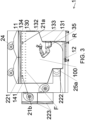
- reference numeral 1 denotes a machine for pharmaceutical or biotechnological processes.
- An embodiment of the machine (1) comprises a structure (10), movement means for moving materials and/or instruments and ventilation means (2).
- the structure (10) has an upper part (11), a lower part (12) and, between them, walls (13, 14, 15, 16).
- the walls comprise a first wall (13) and a second wall (14) which is opposite the first wall (13).
- the movement means are configured to move the materials and/or the instruments in an operating space (100a) internally of the chamber (100).
- the ventilation means (2) comprise at least a fluid injection mouth (21a, 21b) internally of the chamber (100) superiorly of the operating space (100a), at least a fluid extraction mouth (25a, 25b) of fluid from the chamber (100) inferiorly of the operating space (100a) and at least a fluid treatment unit (221) suitable for pharmaceutical or biotechnological processes upstream of the at least an injection mouth (21a, 21b).
- the ventilation means (2) move a fluid from the at least an injection mouth (21a, 21b) to the at least an extraction mouth (25a, 25b).
- the structure (10) is configured so that the horizontal section (A) of the chamber (100) is constant, or substantially constant, or diminishes descending from the at least an injection mouth (21a, 21) to the at least an extraction mouth (25a, 25b).
- the first wall (13) advantageously comprises a first part (131), a second part (132) distanced from the first part (131) according to a horizontal direction (O) and an inclined part (133) which extends between the first part (131) and the second part (132), inferiorly of the second part (132) and superiorly of the first part (131) and which is contiguous with the first part (131) and with the second part (132) so as to confine the chamber (100).
- the operating space (100a) extends, at least partly, above the inclined part (133) and/or and/or in a volume arranged superiorly of the first part (131) and in front of the inclined part (133).
- the inclined part (133) is inclined with respect to a horizontal plane (H) so that the horizontal section (A) of the chamber (100) crossed by the fluid diminishes when falling towards the first part (131).
- the machine (1) of the invention avoids fluid stagnation areas descending towards the at least an extraction mouth (25a, 25b) and facilitates an acceleration of the fluid so as to prevent deposits of contaminant substances or particles and facilitate airborne transport thereof.
- the advantages are appreciable at the inclined part (133) and around the movement means which are often the cause of obstacles, shaded areas and/or sources of emission of contaminant substances or particles from the mechanical parts of the movement means.
- Benefits alike to the ones obtained for the movement means are also attained with respect to any functional units (99) of the process, typically arranged on the inclined part (133) and/or brought from the first part (131), as will be discussed in more detail below.
- the materials and/or the instruments are moved to realise one or more pharmaceutical or biotechnological processes.
- Figures 6 , 7 and 8 are examples of some operating spaces (100a) and illustrate how the operating space (100a) does not necessarily correspond to the space that the movement means can reach but to the space where the materials and/or the instruments are in motion.
- the operating space (100a) represented in figure 7 comprises, with respect to the one of figure 8 , a volume arranged superiorly of the first part (131) and in front of the inclined part (133); in other words arranged between the inclined part (133) and the second wall (14).
- the operating space (100a) preferably extends, at least partly, above the inclined part (133).
- the horizontal section (A) of the chamber (100) may not influence the velocity of the flow and on the ability thereof to perform airborne transport, in this sense the horizontal section (A) can be substantially constant.
- the first wall (13) and the second wall (14) preferably move towards one another, inferiorly of the inclined part (133) and superiorly of the at least an extraction mouth (25a, 25b).
- the nearing movement can be determined by the attitude of the first wall (13) and/or of the second wall (14).
- the second wall (14) preferably has a part (not illustrated), at the height of the inclined part (133), which is inclined so as to reduce the horizontal section (A).
- a further restriction of the horizontal section (A) determined by the second wall (14) internally of the portion corresponding to the inclined part (133) further facilitates the increase of flow velocity with the above-described benefits.
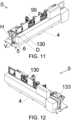
- the second part (132) preferably comprises an opening (130) for introducing or removing materials into/from the chamber (100).
- the machines for pharmaceutical or biotechnological processes are usually provided with similar openings (130) which are often arranged in proximity of the operating space (100a).
- the inclined part (133) thus enables directing the flow that laps the opening (130), as well as the contaminants from the materials that can pass through it, towards the at least an extraction mouth (25a, 25b), while at the same time accelerating the contaminants so as to avoid deposits. In this away a high level of cleanliness can be maintained notwithstanding the presence of areas that are openable towards the outside environment or being passed through.
- the at least an extraction mouth (25a, 25b) can be made on the first wall (13), as can be seen in figure 8 , or on the second wall (14), as shown by way of example in figure 6 , or on both, as shown by way of example in figure 7 .
- the at least an extraction mouth (25a, 25b) can be made on the lower part (12).
- the positioning on the first wall (13) or on the second wall (14) is more convenient especially in the case of filters (222) arranged at the at least an extraction mouth (25a, 25b).
- An extraction mouth (25a) is preferably made on the second wall (14).
- the at least an extraction mouth (25a, 25b) can be made on the first wall (13), when realised on the second wall (14) it generally allows affording a greater volume for the filters (222), useful especially on increasing the volume of the chamber (100) and/or for connections to components of the ventilation means (2) arranged on the external side of the second wall (14). This is advantageous in applications where it is difficult to identify further space, beyond the space normally available for the ventilation means (2) above the upper part (11).
- the chamber (100) of figure 4 requires a filter (222) of greater volume with respect to the filter (222) of the chamber (100) of figure 5 .
- the first wall (13) is preferably connected to the lower part (12) with a fillet and/or the second wall (14) is connected to the lower part (12) with a fillet, the fillet (R) is conformed so as to direct the flow towards the at least an extraction mouth (25a, 25b), consequently improving airborne transport towards the outside of the chamber (100).
- the first wall (13) is connected to the lower part (12) with a fillet
- the second wall (14) is connected to the lower part (12) with a fillet
- the curvature radius of the fillet (R) is preferable for the curvature radius of the fillet (R) to be such that the fillet (R) fronts the at least an extraction mouth (25a, 25b).
- the ventilation means (2) preferably comprise a filter (222) suitable for pharmaceutical or biotechnological processes arranged at an extraction mouth (25a, 25b), so as to clean the fluid from the airborne contaminant substances or particles.
- the ventilation means (2) preferably comprise a recirculation conduit (23) which connects at least an extraction mouth (25a, 25b) to at least an injection mouth (21a, 21b), as schematically illustrated in figures 4 , 7 , and 8 . More preferably the recirculation conduit (23) passes by the side of the second wall (14), instead of by the side of the first wall (13), as occurs in the known solutions.
- the upper part (11) typically houses the at least an injection mouth (21a, 21b) and preferably the ventilation means (2) are configured in such a way that the flow is laminar, or substantially laminar, at least in a first portion (F), and directed perpendicularly to a horizontal plane (H).
- Laminar flows are often used in cleanrooms because of the directional aspect thereof and, in the case of the machine (1) of the invention, ensure good airborne transport for a first portion (F) typically free of obstacles, then to be channelled towards extraction.
- the machine (1) comprises a separator wall (9) of the chamber (100); the separator wall (9) extends from the upper part (11) towards the lower part (12) to a height of the first part (131).
- the separator wall (9) thus realises a configuration alike to a RABS, with a part of the chamber (100) not suffering contaminations of the part of chamber (100) in which the movement means are installed and in which the inclined part (133) is present as well as, possibly, the opening (130).
- the at least an injection mouth (21a, 21b) extends, or extends substantially, over all the horizontal section (A) of the chamber (100).
- the flow covers the whole horizontal section (A) so as to prevent the presence of areas of contaminant accumulation.
- the at least an injection mouth (21a, 21b) preferably extends, or extends substantially, from the first wall (13) to the second wall (14) and, more preferably, also from another of the walls (15, 16) adjacent to the first wall (13) and the second wall (14).
- the first wall (13) and the second wall (14) preferably both have a flat vertical part (134, 141) which descends from the upper part (11) and lies on a respective vertical plane (Z). In this way stagnation areas, and possibly the laminar flow does not deviate, modifying the directionality thereof.
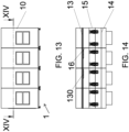
- the walls (15, 16) adjacent to the first wall (13) and the second wall (14) are flat and vertical, i.e. they lie on vertical planes, as in figure 14 ; in other embodiments they can contribute to reducing the horizontal section (A).
- the movement means can comprise transporters or conveyors, such as, for example, conveyor belts, mechanical arms, robotic arms and/or other known devices.
- the movement means preferably comprise an arm (33).
- the machine (1) of the invention advantageously avoids contaminant accumulation and guarantees airborne transport even in the presence of the arm (33).
- the arm (33) can be a mechanical arm or a robotic arm.
- the movement means typically also comprise a contact part (34), borne by a respective arm (33), which contacts the materials and/or the instruments internally of the operating space (100a).
- the movement means can comprise devices borne by the walls (13, 14, 15, 16) and/or by the upper part (11) and/or by the inclined part (133).
- the movement means comprise a plurality of devices.
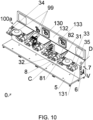
- the movement means preferably comprise at least a robot (31, 32). More preferably each robot (31, 32) comprises an arm (33) and a contact part (34) and is configured to move the contact part (34) into the operating space (100a).
- the movement means or the at least a robot (31, 32), preferably comprise a part (35) that is coupled to or crosses the first part (131) and/or the inclined part (133) so as to be able to easily receive energy and/or materials.
- the machine (1) preferably comprises means for supplying energy (6) to the movement means and/or means for supplying materials (7) to the movement means arranged at the first part (131) or at the inclined part (133) on the side opposite the chamber (100), so that they are in proximity of the operating space (100a).
- the means for supplying energy (6) and/or the means for supplying materials (7) are located below the inclined part (133), internally of a volume which in the prior art solutions was typically exploited for the passage of air conduits.
- the machine (1) preferably comprises at least a functional group (99) which cooperates with the movement means to realise a pharmaceutical or biotechnological process.
- the at least a functional group (99) can comprise weighing systems, collecting systems, container-closing systems, ring-sealing stations, liquid or powder dosing systems, parking areas for containers or caps, carousels, centrifuges or other devices commonly used in the pharmaceutical or biotechnological industry.
- the inclined part (133) more preferably accommodates or supports at least a functional group (99) and/or the first part (131) supports at least a functional group (99).
- the operating space (100a) enables the movement means to operate above the inclined part (133) and on any functional units (99) born by the first part (131).
- the definition of the operating space (100a) takes account of the position of the at least a functional group (99) which involves the pharmaceutical or biotechnological process to be carried out.
- the ventilation means (2) preferably comprise at least a ventilator (24).
- a ventilator (24) is arranged above the upper part (11) and other ventilators (24) can be introduced to manage overpressure or depression internally of the inside of the chamber (100) as well as the volumes of suction, emission towards the outside and recovery.
- other ventilators (24) are arranged on the side of the second wall (14) in figures from 3 to 9 and enable dynamic management of the recirculation and the pressure internally of the chamber (100).
- the at least a fluid treatment unit (221) preferably comprises a filter, more preferably of the HEPA type for pharmaceutical or biotechnological processes.
- the ventilation means (2) typically comprise a filter (222) for filtering the air in outlet to the chamber (100), preferably of the HEPA type suitable for pharmaceutical or biotechnological processes.
- the ventilation means (2) commonly also comprise a filter (223) for filtering the air in towards the outside or from the outside, preferably of the HEPA type for pharmaceutical or biotechnological processes.
- the at least a fluid treatment unit (221) preferably comprises a fluid cooling and/or heating unit.
- the means for supplying energy (6) can comprise electric cables, electrical control units, conduits for pressurised fluids or other devices commonly used in the pharmaceutical, biotechnological or robotic industry.
- the means for supplying materials (7) can comprise pipes for fluids, such as for example water, air or nitrogen, or mechanical parts for openings and/or drawers and/or compartments, pumps, valves or other devices commonly used in the pharmaceutical or biotechnological industry.
- pipes for fluids such as for example water, air or nitrogen
- mechanical parts for openings and/or drawers and/or compartments, pumps, valves or other devices commonly used in the pharmaceutical or biotechnological industry By way of example, in figure 10 a compartment open towards the chamber is partially visible, in a dotted line, openable towards the chamber (100).
- the materials can comprise containers or parts thereof, pharmaceutical products, biotechnological products, products for tests, or other materials used for pharmaceutical or biotechnological processes.
- the instruments can comprise gripping organs, such as, for example pincers, measuring instruments, pick-up devices, filling devices or other instruments used for pharmaceutical or biotechnological processes.
- gripping organs such as, for example pincers, measuring instruments, pick-up devices, filling devices or other instruments used for pharmaceutical or biotechnological processes.
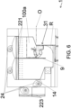
- the invention also relates to an assembly (0) for manufacturing the machine (1) according to the present description.
- An embodiment of the assembly (0) comprises:
- the assembly (0) according to the invention facilitates the construction of the machine (1) as it comprises components essential for realising pharmaceutical or biotechnological processes in a chamber (100) with the above-delineated advantages.
- the assembly (0) can be, for example, pre-validated or pre-qualified and subsequently transported to another place for assembly with the other parts of structure so as to build the machine (1) of the invention.
- the assembly (0) can easily be integrated into very different structures to one another, while guaranteeing high levels of cleanliness internally of the chamber (100).
- the assembly (0) is further more easily transportable than the whole machine (1) and transport means for delicate or fragile objects can more easily be used.
- the parts of wall preferably also comprise a second part (132), more preferably comprising an opening (130), as can be observed for example in figure 10 . This can be useful for further limiting the successive operations and maximising the operations before obtaining the prefabricated assembly (0).
- the movement means preferably comprise a part (35) that is coupled to or crosses the first part (131) and/or the inclined part (133) so as to be on the opposite side to the volume (V) and to be easily energised or to be able to easily receive materials.
- the assembly (0) preferably comprises a separation part (8) and the movement means comprise a first device and a second device.
- the separation part (8) is arranged above the inclined part (133) between the first device and the second device and has a first oblique surface (81) and a second oblique surface (82) facing on opposite sides and which broaden towards the inclined part (133) in the conjoining direction (C) of the first device and of the second device.
- the separation part (8) can interface with or accommodate a wall (15, 16) so as to delimit therewith the chamber (100) thus facilitating the distancing of the flow from the wall (15, 16) due to the oblique surface, for the same reasons already adopted by the inclined part (133).
- the advantages increase when the wall (15, 16) comprises an opening.
- the invention also relates to a method for manufacturing the machine (1) according to the present description.
- the above-described method enables exploiting the advantages of having a prefabricated assembly (0), typically pre-qualified, to form a chamber (100) suitable for the specific requirements of the particular pharmaceutical or biotechnological process.
- the machine (1) of the invention thus becomes available rapidly and/or can be personalised quickly, as well as having lower costs with respect to those deriving from zero design and manufacturing operations.
- an assembly is preferably provided that comprises a separation part (8), with the movement means comprising a first device and a second device.
- the separation part (8) is arranged above the inclined part (133) between the first device and the second device and has a first oblique surface (81) and a second oblique surface (82) facing on opposite sides and which broaden towards the inclined part (133) in the conjoining direction (C) of the first device and of the second device.
- a separation part (8) is connected to a wall (13, 14, 15, 16) in such a way that the wall (13, 14, 15, 16) extends between the first oblique surface (81) and the second oblique surface (82).
- Figure 1 illustrates accesses, for example for maintenance, not strictly necessary.
- Figure 2 illustrates some openings (130) and the in-view wall provided with openings of the RTP type, an acronym for Rapid Transfer Port.
- the machine (1) of the invention can comprise further chambers.
- a single chamber (100) can be realised or a chamber (100) and further chambers, three in the case of figure 14 .
- the machine (1) realised can comprise three further chambers with an outer conformation that can be the one illustrated in figure 1 .
- the assembly (0) illustrated in the following, can be made with a "modular" approach guaranteeing one or more stations.
- substantially four areas of fluid velocity or horizontal strips can be observed, starting from above: a first area reaching to the inclined part (133), a second area at the inclined part (133), a third area beneath the inclined part (133) and reaching to the end of the inclination of the second wall (14) and a fourth lower area.
- the opening (130) is represented in figure 3 , but this might also be present in the other embodiments, as can the fillet (R).
- the base (5) comprises, though this is not strictly necessary, a platform which extends from the first part (131).
- the platform facilitates the transport and management of the assembly (0) before realising the machine (1), while protecting the area with the movement means and, possibly, the functional units (99).
- the assembly (0) can be easily integrated with functional units (99), i.e. modules or devices commonly used in the pharmaceutical or biotechnological industry, ensuring, among other things, a greater facility of access during the installation with respect to installation on a machine (1).
- functional units i.e. modules or devices commonly used in the pharmaceutical or biotechnological industry
Landscapes
- Engineering & Computer Science (AREA)
- Mechanical Engineering (AREA)
- Robotics (AREA)
- Health & Medical Sciences (AREA)
- Chemical & Material Sciences (AREA)
- Physics & Mathematics (AREA)
- Signal Processing (AREA)
- Business, Economics & Management (AREA)
- General Health & Medical Sciences (AREA)
- Clinical Laboratory Science (AREA)
- Chemical Kinetics & Catalysis (AREA)
- Epidemiology (AREA)
- Animal Behavior & Ethology (AREA)
- Primary Health Care (AREA)
- Strategic Management (AREA)
- Tourism & Hospitality (AREA)
- Human Resources & Organizations (AREA)
- General Business, Economics & Management (AREA)
- General Physics & Mathematics (AREA)
- Theoretical Computer Science (AREA)
- Economics (AREA)
- Life Sciences & Earth Sciences (AREA)
- Marketing (AREA)
- Public Health (AREA)
- Veterinary Medicine (AREA)
- Manufacturing & Machinery (AREA)
- Fuzzy Systems (AREA)
- Mathematical Physics (AREA)
- Combustion & Propulsion (AREA)
- General Engineering & Computer Science (AREA)
- Apparatus Associated With Microorganisms And Enzymes (AREA)
- Manipulator (AREA)
- Infusion, Injection, And Reservoir Apparatuses (AREA)
- Central Air Conditioning (AREA)
- Ventilation (AREA)
Claims (17)
- Maschine (1) für pharmazeutische oder biotechnologische Prozesse, umfassend:- eine Struktur (10), die einen oberen Teil (11), einen unteren Teil (12) und zwischen dem oberen Teil (11) und dem unteren Teil (12) Wände (13, 14, 15, 16) aufweist, die eine erste Wand (13) und eine zweite Wand (14) gegenüber der ersten Wand (13) und dem oberen Teil (11) umfassen, wobei der untere Teil (12) und die Wände (13, 14, 15, 16) eine Kammer (100) begrenzen;- Bewegungsmittel zum Bewegen von Materialien und/oder Instrumenten, die so konfiguriert sind, dass sie die Materialien und/oder die Instrumente in einem Arbeitsraum (100a) im Inneren der Kammer (100) bewegen;- Belüftungsmittel (2), die mindestens eine Fluidinjektionsöffnung (21a, 21b) innerhalb der Kammer (100) oberhalb des Arbeitsraums (100a), mindestens eine Fluidentnahmeöffnung (25a, 25b) für Fluid aus der Kammer (100) unterhalb des Arbeitsraums (100a) und mindestens eine Fluidbehandlungseinheit (221), die für pharmazeutische oder biotechnologische Prozesse geeignet ist, stromaufwärts der mindestens einen Injektionsöffnung (21a, 21b), wobei die Belüftungseinrichtung (2) ein Fluid von der mindestens einen Injektionsöffnung (21a, 21b) zu der mindestens einen Extraktionsöffnung (25a, 25b) bewegt;
wobei die erste Wand (13) einen ersten Teil (131), einen zweiten Teil (132) und einen geneigten Teil (133) umfasst, der sich zwischen dem ersten Teil (131) und dem zweiten Teil (132) unterhalb des zweiten Teils (132) und oberhalb des ersten Teils (131) erstreckt und der an den ersten Teil (131) und an den zweiten Teil (132) angrenzt, um die Kammer (100) zu begrenzen;- der Arbeitsraum (100a) sich zumindest teilweise oberhalb des geneigten Teils (133) und/oder in einem oberhalb des ersten Teils (131) und vor dem geneigten Teil (133) angeordneten Volumen erstreckt;- der geneigte Teil (133) in Bezug auf eine horizontale Ebene (H) derart geneigt ist, dass der horizontale Querschnitt (A) der Kammer (100), der von dem Fluid durchquert wird, sich beim Abstieg in Richtung des ersten Teils (131) verringert, wobei die Maschine dadurch gekennzeichnet ist, dass die Struktur (10) derart konfiguriert ist, dass der horizontale Querschnitt (A) der Kammer (100) konstant oder im Wesentlichen konstant ist oder sich beim Abstieg von der mindestens einen Einspritzmündung (21a, 21b) zu der mindestens einen Entnahmemündung (25a, 25b) verkleinert; und dass der zweite Teil (132) von dem ersten Teil (131) in einer horizontalen Richtung (O) beabstandet ist. - Maschine nach dem vorhergehenden Anspruch, bei der die erste Wand (13) und die zweite Wand (14) unterhalb des geneigten Teils (133) und oberhalb der mindestens einen Extraktionsöffnung (25a, 25b) nahe beieinander liegen.
- Die Maschine (1) nach einem der vorhergehenden Ansprüche, wobei der zweite Teil (132) eine Öffnung (130) zum Einführen von Materialien in die Kammer (100) oder zum Entnehmen von Materialien aus der Kammer (100) aufweist
und wobei sich der Arbeitsraum (100a) zumindest teilweise oberhalb des geneigten Teils (133) erstreckt. - Die Maschine (1) nach einem der vorhergehenden Ansprüche, wobei eine Entnahmemündung (25a) an der zweiten Wand (14) ausgebildet ist.
- Maschine (1) nach einem der vorhergehenden Ansprüche, wobei die mindestens eine Absaugmündung (25a, 25b) an der ersten Wand (13) und/oder nach Anspruch 4 ausgebildet ist und wobei jeweils die zweite Wand (14) und/oder die erste Wand (13) mit dem Unterteil (12) durch eine Ausrundung verbunden ist, wobei die Ausrundung (R) so ausgebildet ist, dass sie die Strömung zu der mindestens einen Absaugmündung (25a, 25b) leitet.
- Maschine (1) nach einem der vorhergehenden Ansprüche, wobei der obere Teil (11) die mindestens eine Einspritzmündung (21a, 21b) beherbergt und wobei die Belüftungsmittel (2) so gestaltet sind, dass die Strömung zumindest in einem ersten Abschnitt (F) laminar oder im Wesentlichen laminar ist und senkrecht zu einer horizontalen Ebene (H) gerichtet ist.
- Maschine (1) nach dem vorhergehenden Anspruch, umfassend eine Trennwand (9) der Kammer (100), wobei sich die Trennwand (9) vom oberen Teil (11) zum unteren Teil (12) bis zu einer Höhe des ersten Teils (131) erstreckt.
- Die Maschine (1) nach einem der vorhergehenden Ansprüche, wobei sich die mindestens eine Einspritzöffnung (21a, 21b) über den gesamten horizontalen Abschnitt (A) der Kammer (100) erstreckt oder im Wesentlichen erstreckt.
- Maschine (1) nach einem der vorhergehenden Ansprüche, wobei die erste Wand (13) und die zweite Wand (14) jeweils einen flachen vertikalen Teil (134, 141) aufweisen, der von dem oberen Teil (11) abfällt und in einer jeweiligen vertikalen Ebene (Z) liegt.
- Die Maschine (1) nach einem der vorhergehenden Ansprüche, wobei die an die erste Wand (13) und die zweite Wand (14) angrenzenden Wände (15, 16) flach und vertikal sind.
- Maschine (1) nach einem der vorhergehenden Ansprüche, wobei die Bewegungseinrichtung ein Teil (35) umfasst, das mit dem ersten Teil (131) und/oder dem geneigten Teil (133) gekoppelt ist oder dieses kreuzt.
- Maschine (1) nach einem der vorhergehenden Ansprüche, umfassend Mittel zur Zuführung von Energie (6) zu den Bewegungsmitteln und/oder Mittel zur Zuführung von Materialien (7) zu den Bewegungsmitteln, die an dem ersten Teil (131) oder an dem schrägen Teil (133) auf der der Kammer (100) gegenüberliegenden Seite angeordnet sind,
wobei die Mittel zur Energiezufuhr (6) und/oder die Mittel zur Materialzufuhr (7) unterhalb des schrägen Teils (133) angeordnet sind. - Maschine (1) nach einem der vorhergehenden Ansprüche, umfassend mindestens eine Funktionsgruppe (99), die mit den Bewegungsmitteln zusammenwirkt, um einen pharmazeutischen oder biotechnologischen Prozess zu realisieren,wobei der geneigte Teil (133) mindestens eine Funktionsgruppe (99) der mindestens einen Funktionsgruppe (99) aufnimmt oder trägt und/oderwobei der erste Teil (131) mindestens eine funktionelle Gruppe (99) der mindestens einen funktionellen Gruppe (99) trägt.
- Baugruppe (0) zur Realisierung der Maschine (1) nach einem der vorhergehenden Ansprüche, umfassend:- Wandteile zur Begrenzung einer Kammer (100) mit einem ersten Teil (131) und einem geneigten Teil (133);- mindestens eine weitere Wand (4);- eine Basis (5), die den ersten Teil (131) und die mindestens eine weitere Wand (4) trägt;- Bewegungsmittel zum Bewegen von Materialien und/oder Instrumenten, die zum Bewegen der Materialien und/oder der Instrumente in einem Arbeitsraum (100a) konfiguriert sind;- Mittel zum Zuführen von Energie (6) zu den Bewegungsmitteln und/oder Mittel zum Zuführen von Materialien (7) zu den Bewegungsmitteln;wobei:- der geneigte Teil (133) an den ersten Teil (131) angrenzt und von dem ersten Teil (131) in einer schrägen Richtung (D) in Bezug auf eine horizontale Ebene (H) ansteigt, wobei die Anordnung (O) dadurch gekennzeichnet ist, dass die Basis (5), der erste Teil (131), der geneigte Teil (133) und die mindestens eine weitere Wand (4) ein Volumen (V) begrenzen, das die Mittel zur Energiezufuhr (6) und/oder die Mittel zur Materialzufuhr (7) aufnimmt.
- Baugruppe (0) nach dem vorhergehenden Anspruch, umfassend ein Trennteil (8), wobei:- die Bewegungsmittel eine erste Vorrichtung und eine zweite Vorrichtung umfassen;- das Trennteil (8) oberhalb des schrägen Teils (133) zwischen der ersten Vorrichtung und der zweiten Vorrichtung angeordnet ist und eine erste Schrägfläche (81) und eine zweite Schrägfläche (82) aufweist, die auf gegenüberliegenden Seiten liegen und sich in Richtung des schrägen Teils (133) in der Verbindungsrichtung (C) der ersten Vorrichtung und der zweiten Vorrichtung verbreitern.
- Verfahren zur Realisierung der Maschine (1) nach einem der vorhergehenden Ansprüche 1 bis 13, umfassend die Schritte:- Bereitstellen einer Baugruppe (0) nach Anspruch 14 oder 15;- Bereitstellen von Teilen, die ein Oberteil (11), ein Unterteil (12), Wände (13, 14, 15, 16) und ein zweites Wandteil (132) umfassen, die so gestaltet sind, dass sie zusammen mit den Wandteilen eine Struktur (10) bilden, wobei das Oberteil (11), das Unterteil (12) und die Wände (13, 14, 15, 16) die Kammer (100) begrenzen;- Vorsehen von Belüftungsmitteln (2), die mindestens eine für pharmazeutische oder biotechnologische Prozesse geeignete Fluidbehandlungseinheit (221), mindestens eine Fluidinjektionsöffnung (21a, 21b) und mindestens eine Fluidentnahmeöffnung (25a, 25b) umfassen;- Verbinden der Teile mit der Einheit (0), um eine erste Wand (13) zu realisieren, die einen ersten Teil (131), einen zweiten Teil (132), der von dem ersten Teil (131) gemäß einer horizontalen Richtung (O) beabstandet ist, und einen geneigten Teil (133) umfasst, der an den zweiten Teil (132) angrenzt und der sich zwischen dem ersten Teil (131) und dem zweiten Teil (132) erstreckt, unterhalb des zweiten Teils (132) und oberhalb des ersten Teils (131) erstreckt, um eine Struktur (10) zu realisieren, die einen horizontalen Querschnitt (A) der Kammer (100) aufweist, der konstant oder im Wesentlichen konstant ist oder vom Installationsbereich der mindestens einen Einspritzmündung (21a, 21b) zum Installationsbereich der mindestens einen Entnahmemündung (25a, 25b) hin abnimmt;- Installieren der Belüftungseinrichtung (2), so dass die mindestens eine Fluideinspritzmündung (21a, 21b) oberhalb des Arbeitsraums (100a) und die mindestens eine Fluidabsaugmündung (25a, 25b) von der Kammer (100) unterhalb des Arbeitsraums (100a) liegt, und so, dass ein Fluid von der mindestens einen Einspritzmündung (21a, 21b) zu der mindestens einen Absaugmündung (25a, 25b) bewegt wird.
- Verfahren nach dem vorhergehenden Anspruch, wobei im Schritt des Bereitstellens einer Baugruppe (0) eine Baugruppe (0) nach Anspruch 15 bereitgestellt wird und wobei im Schritt des Verbindens der Teile mit der Baugruppe (0) ein Trennteil (8) mit einer Wand (13, 14, 15, 16) verbunden wird, so dass sich die Wand (13, 14, 15, 16) zwischen der ersten Schrägfläche (81) und einer zweiten Schrägfläche (82) erstreckt.
Applications Claiming Priority (2)
| Application Number | Priority Date | Filing Date | Title |
|---|---|---|---|
| EP21202343.6A EP4166288A1 (de) | 2021-10-13 | 2021-10-13 | Vorgefertigtes automatisches unbemanntes und handschuhfreies gehäuse für ein reinraumverfahren |
| PCT/IB2022/059735 WO2023062530A1 (en) | 2021-10-13 | 2022-10-11 | Machine for pharmaceutical or biotechnological processes, assembly and method for realising the machine |
Publications (2)
| Publication Number | Publication Date |
|---|---|
| EP4267889A1 EP4267889A1 (de) | 2023-11-01 |
| EP4267889B1 true EP4267889B1 (de) | 2024-05-01 |
Family
ID=78414208
Family Applications (2)
| Application Number | Title | Priority Date | Filing Date |
|---|---|---|---|
| EP21202343.6A Pending EP4166288A1 (de) | 2021-10-13 | 2021-10-13 | Vorgefertigtes automatisches unbemanntes und handschuhfreies gehäuse für ein reinraumverfahren |
| EP22801225.8A Active EP4267889B1 (de) | 2021-10-13 | 2022-10-11 | Maschine für pharmazeutische oder biotechnologische verfahren, zusammenbau und verfahren zur realisierung der maschine |
Family Applications Before (1)
| Application Number | Title | Priority Date | Filing Date |
|---|---|---|---|
| EP21202343.6A Pending EP4166288A1 (de) | 2021-10-13 | 2021-10-13 | Vorgefertigtes automatisches unbemanntes und handschuhfreies gehäuse für ein reinraumverfahren |
Country Status (10)
| Country | Link |
|---|---|
| US (2) | US20250065517A1 (de) |
| EP (2) | EP4166288A1 (de) |
| JP (2) | JP2024541196A (de) |
| KR (1) | KR20240089517A (de) |
| CN (1) | CN118140095A (de) |
| CA (1) | CA3234357A1 (de) |
| DK (1) | DK4267889T3 (de) |
| ES (1) | ES2982849T3 (de) |
| HU (1) | HUE067553T2 (de) |
| WO (2) | WO2023062530A1 (de) |
Citations (5)
| Publication number | Priority date | Publication date | Assignee | Title |
|---|---|---|---|---|
| EP1426122A1 (de) | 2002-11-29 | 2004-06-09 | Extract Technology Limited | Isolator |
| EP2995361A1 (de) | 2010-06-18 | 2016-03-16 | Airex Co., Ltd. | Filtereinheit |
| EP3170545A1 (de) | 2015-11-23 | 2017-05-24 | Skan Ag | Filtersystem für ein von einem gasstrom durchflossenes containment |
| EP3335844A1 (de) | 2016-12-15 | 2018-06-20 | Pharma Integration S.R.L. | Konstruktiver aufbau eines containments, bestimmt zur automatisierten produktion pharmazeutischer oder biotechnischer artikel |
| WO2020016645A2 (de) | 2018-07-18 | 2020-01-23 | Pharma Integration S.R.L. | Anordnung zum kontaminationsfreien einschleusen eines sterilen objektes aus einem behältnis in ein containment und verfahren dazu |
Family Cites Families (4)
| Publication number | Priority date | Publication date | Assignee | Title |
|---|---|---|---|---|
| FR2565598B1 (fr) * | 1984-06-06 | 1986-10-03 | Inst Nat Sante Rech Med | Appareil modulaire pour la culture cellulaire |
| JP3261705B2 (ja) * | 1991-05-22 | 2002-03-04 | 株式会社日立製作所 | 簡易クリーンルーム |
| WO2016132398A1 (ja) * | 2015-02-19 | 2016-08-25 | 日揮株式会社 | 細胞培養加工設備 |
| DE102019214849A1 (de) * | 2019-09-27 | 2021-04-01 | Bausch + Ströbel Maschinenfabrik Ilshofen GmbH + Co. KG | Produktionseinrichtung, insbesondere für die pharmaindustrie |
-
2021
- 2021-10-13 EP EP21202343.6A patent/EP4166288A1/de active Pending
-
2022
- 2022-10-11 CN CN202280070803.7A patent/CN118140095A/zh active Pending
- 2022-10-11 HU HUE22801225A patent/HUE067553T2/hu unknown
- 2022-10-11 EP EP22801225.8A patent/EP4267889B1/de active Active
- 2022-10-11 CA CA3234357A patent/CA3234357A1/en active Pending
- 2022-10-11 ES ES22801225T patent/ES2982849T3/es active Active
- 2022-10-11 DK DK22801225.8T patent/DK4267889T3/da active
- 2022-10-11 US US18/700,505 patent/US20250065517A1/en active Pending
- 2022-10-11 JP JP2024522202A patent/JP2024541196A/ja active Pending
- 2022-10-11 WO PCT/IB2022/059735 patent/WO2023062530A1/en not_active Ceased
- 2022-10-11 KR KR1020247015460A patent/KR20240089517A/ko active Pending
- 2022-10-13 US US18/699,614 patent/US20240408774A1/en active Pending
- 2022-10-13 WO PCT/EP2022/078564 patent/WO2023062152A1/en not_active Ceased
- 2022-10-13 JP JP2024522209A patent/JP2024537343A/ja active Pending
Patent Citations (5)
| Publication number | Priority date | Publication date | Assignee | Title |
|---|---|---|---|---|
| EP1426122A1 (de) | 2002-11-29 | 2004-06-09 | Extract Technology Limited | Isolator |
| EP2995361A1 (de) | 2010-06-18 | 2016-03-16 | Airex Co., Ltd. | Filtereinheit |
| EP3170545A1 (de) | 2015-11-23 | 2017-05-24 | Skan Ag | Filtersystem für ein von einem gasstrom durchflossenes containment |
| EP3335844A1 (de) | 2016-12-15 | 2018-06-20 | Pharma Integration S.R.L. | Konstruktiver aufbau eines containments, bestimmt zur automatisierten produktion pharmazeutischer oder biotechnischer artikel |
| WO2020016645A2 (de) | 2018-07-18 | 2020-01-23 | Pharma Integration S.R.L. | Anordnung zum kontaminationsfreien einschleusen eines sterilen objektes aus einem behältnis in ein containment und verfahren dazu |
Non-Patent Citations (24)
| Title |
|---|
| ANONYMOUS: "Cell and Gene Therapy ATMPs", PRODUKTKATALOG- SKAN, 1 January 2021 (2021-01-01), pages 1 - 16, XP093259541 |
| ANONYMOUS: "INTEGRA – a Groninger and SKAN solution wins the Achema innovation award in the category "Filling and Packaging"", SKAN, 3 July 2018 (2018-07-03), pages 1 - 3, XP093259508, Retrieved from the Internet <URL:https://skan.com/en/integra-a-groninger-and-skan-solution-wins-the-achema-innovation-award-in-the-category-filling-and-packaging/> [retrieved on 20250123] |
| ANONYMOUS: "Our expertise in the pharmaceutical industry ", PRODUKTKATALOG -STÄUBLI, 1 February 2022 (2022-02-01), pages 1 - 11, XP093259555 |
| ANONYMOUS: "Robotic vial filling machine RVFM ", PRODUKTKATALOG - STERILINE ASEPTIC PROCESSING, 1 September 2018 (2018-09-01), pages 1 - 3, XP093259551 |
| ANONYMOUS: "Steriline products and solutions: Robotic applications", EPR - EUROPEAN PHARMACEUTICAL REVIEW, 21 May 2019 (2019-05-21), pages 1 - 4, XP093259499, Retrieved from the Internet <URL:https://www.europeanpharmaceuticalreview.com/product/88306/steriline-products-and-solutions-robotic-applications/> [retrieved on 20250129] |
| ANONYMOUS: "SteriLne ASEPTIC PROCESSING", STERILINE - PRODUCT CATALOGUE, 1 October 2020 (2020-10-01), pages 1 - 27, XP093259548 |
| ANONYMOUS: "VARIOSYS", SKAN- PRODUKTKATALOG, 1 November 2019 (2019-11-01), pages 1 - 40, XP093259537 |
| AQVIDA GMBH: "Our new robotic filling line in action", YOUTUBE, 13 December 2016 (2016-12-13), XP093259481, Retrieved from the Internet <URL:https://www.youtube.com/watch?v=TlH85ZcFmWA> [retrieved on 20250131] |
| CPHI GLOBAL PHARMA EVENTS: "Groninger at CPhI and P-MEC India 2018", YOUTUBE, 14 December 2018 (2018-12-14), XP093259517, Retrieved from the Internet <URL:https://www.youtube.com/watch?v=ABt4rfbSJJI> [retrieved on 20250131] |
| D25 - Transkript des Videos D23 |
| D26 - Transkript des Videos D24 |
| D7- Offenkundige Vorbenutzung des SKAN Integra Isolators auf der Messe ACHEMA 2018, Messezeitraum 11.06.2018 – 15.06.2018 |
| ERNHOFER WOLFGANG: "Die 11 innovativsten Produkte und Lösungen der Achema ausgezeichnet", PROCESS, 13 June 2018 (2018-06-13), pages 1 - 5, XP093259513, Retrieved from the Internet <URL:https://www.process.vogel.de/die-11-innovativsten-produkte-und-loesungen-der-achema-ausgezeichnet-a-724170/> [retrieved on 20250128] |
| GAPP GUENTHER , SHELLEY PRESLAR, MARCIA CRISTINA BARONI,HAROLD BASEMAN,JETTE CHRISTENSEN,RICHARD DENK,PHIL DESANTIS,DAWN DOWNEY,SA: "Points to Consider for the Aseptic Processing of Sterile Pharmaceutical Products in Isolators ", PARENTERAL DRUG ASSOCIATION INC, 1 January 2020 (2020-01-01), pages 1 - 85, XP093259561 |
| GRONINGER GROUP: "groninger @ ACHEMA 2018 - Visions become Reality", YOUTUBE, 29 June 2018 (2018-06-29), XP093259510, Retrieved from the Internet <URL:https://www.youtube.com/watch?v=3b7c8VL2eXQ> [retrieved on 20250131] |
| HANS-JüRGEN BäSSLER AND FRANK LEHMANN: "Containment Technology", 11 October 2013, SPRINGER-VERLAG , Berlin, Heidelberg , ISBN: 978-3-642-39291-7, article HANS-JURGEN BASSLER , FRANK LEHMANN: "Front Matter; Containment Technology", pages: i - xix, XP009561197, DOI: 10.1007/978-3-642-39292-4 |
| MAZAKEUROPE: "OPTIPLEX 4020 DDL - Steriline", YOUTUBE, 5 April 2022 (2022-04-05), XP093259501, Retrieved from the Internet <URL:https://www.youtube.com/watch?v=ih4B60NyNCw> [retrieved on 20220405] |
| MILLIPORESIGMA: "Isolator Fill-Finish Process with Single-Use Systems", YOUTUBE, 29 April 2022 (2022-04-29), XP093259468, Retrieved from the Internet <URL:https://www.youtube.com/watch?v=KSSoWkt4FNI> [retrieved on 20250131] |
| PSM - YOUR PHARMA CDMO: "Ankunft der robocell bei der PSM GmbH", YOUTUBE, 8 September 2022 (2022-09-08), XP093259525, Retrieved from the Internet <URL:https://www.youtube.com/watch?v=1VCtAkgS0rs> [retrieved on 20250203] |
| PSM - YOUR PHARMA CDMO: "The PSM GmbH was in Basel at SKAN AG for the FAT", YOUTUBE, 19 May 2022 (2022-05-19), XP093259522, Retrieved from the Internet <URL:https://www.youtube.com/watch?v=Z1C74z_az5s> [retrieved on 20250203] |
| SHARP STERILE MANUFACTURING: "An Introduction to Isolator Technology", YOUTUBE, 12 October 2021 (2021-10-12), XP093259477, Retrieved from the Internet <URL:https://www.youtube.com/watch?v=gyqRb6fgC1Y&t=58s> [retrieved on 20250131] |
| SKAN: "Interphex NY 2019 - A SKAN solutions overview | SKAN", YOUTUBE, 17 June 2019 (2019-06-17), XP093259515, Retrieved from the Internet <URL:https://www.youtube.com/watch?v=rIy8uAZGFUI> [retrieved on 20250131] |
| SKAN: "Robotics and automated processes in isolators | SKAN", YOUTUBE, 24 February 2021 (2021-02-24), XP093259471, Retrieved from the Internet <URL:https://www.youtube.com/watch?v=LmBhg9Dm-c0> [retrieved on 20250131] |
| STÄUBLI ROBOTICS: "Filling and closing machine for small batches with Stäubli TX60 stericlean robots", YOUTUBE, 17 March 2017 (2017-03-17), XP093259487, Retrieved from the Internet <URL:https://www.youtube.com/watch?v=PMjqndH7Byg> [retrieved on 20250131] |
Also Published As
| Publication number | Publication date |
|---|---|
| WO2023062152A1 (en) | 2023-04-20 |
| JP2024537343A (ja) | 2024-10-10 |
| EP4267889A1 (de) | 2023-11-01 |
| CA3234357A1 (en) | 2023-04-20 |
| KR20240089517A (ko) | 2024-06-20 |
| ES2982849T3 (es) | 2024-10-17 |
| US20240408774A1 (en) | 2024-12-12 |
| US20250065517A1 (en) | 2025-02-27 |
| EP4166288A1 (de) | 2023-04-19 |
| DK4267889T3 (da) | 2024-07-29 |
| WO2023062530A1 (en) | 2023-04-20 |
| CN118140095A (zh) | 2024-06-04 |
| HUE067553T2 (hu) | 2024-10-28 |
| JP2024541196A (ja) | 2024-11-08 |
Similar Documents
| Publication | Publication Date | Title |
|---|---|---|
| CN115812023A (zh) | 用于操纵物体的设备、用于填充物体的方法和相应的应用 | |
| JP4344593B2 (ja) | ミニエンバイロメント装置、薄板状物製造システム及び清浄容器の雰囲気置換方法 | |
| KR0180793B1 (ko) | 디스크형 물체를 수용하기 위한 매거진 운반장치 | |
| US5371950A (en) | Isopropyl alcohol vapor dryer system | |
| US8282698B2 (en) | Reduction of particle contamination produced by moving mechanisms in a process tool | |
| EP2007633B1 (de) | System und verfahren zum übertragen und bewegen von elementen einer automatischen verpackungsmaschine | |
| US8984744B2 (en) | Method and apparatus to support a cleanspace fabricator | |
| US6792958B2 (en) | System for processing substrate with liquid | |
| US5660585A (en) | Facility and method for the handling of objects | |
| EP4267889B1 (de) | Maschine für pharmazeutische oder biotechnologische verfahren, zusammenbau und verfahren zur realisierung der maschine | |
| EP3088902B1 (de) | Vorrichtung zum entnehmen eines stopfens | |
| US9159592B2 (en) | Method and apparatus for an automated tool handling system for a multilevel cleanspace fabricator | |
| US20150158057A1 (en) | Processing system for powders, and method for processing powders | |
| US20150141225A1 (en) | Method and apparatus to support process tool modules in processing tools in a cleanspace fabricator | |
| CA2403734A1 (en) | Cabinets for handling toxic or sterile materials | |
| KR20010042724A (ko) | 구조적 배열체를 통한 유체 유동용 시브형 구조체 | |
| WO1998043878A1 (en) | Filling machine having clean air system | |
| EP0513967A2 (de) | Automatisierte, nasschemische Behandlungsvorrichtung | |
| US20090249744A1 (en) | Packing machine | |
| US10627809B2 (en) | Multilevel fabricators | |
| Bässler et al. | Robotics in a sterile Pharma Isolator. | |
| US20200176289A1 (en) | Method and apparatus for multilevel fabricators | |
| EP2289808A1 (de) | Vorrichtung geeignet zum Verbinden einer ersten Lagereinheit mit einer zweiten Lagereinheit sowie entsprechendes Verfahren | |
| JP3800494B2 (ja) | 包装施設 |
Legal Events
| Date | Code | Title | Description |
|---|---|---|---|
| STAA | Information on the status of an ep patent application or granted ep patent |
Free format text: STATUS: UNKNOWN |
|
| STAA | Information on the status of an ep patent application or granted ep patent |
Free format text: STATUS: THE INTERNATIONAL PUBLICATION HAS BEEN MADE |
|
| PUAI | Public reference made under article 153(3) epc to a published international application that has entered the european phase |
Free format text: ORIGINAL CODE: 0009012 |
|
| STAA | Information on the status of an ep patent application or granted ep patent |
Free format text: STATUS: REQUEST FOR EXAMINATION WAS MADE |
|
| 17P | Request for examination filed |
Effective date: 20230728 |
|
| AK | Designated contracting states |
Kind code of ref document: A1 Designated state(s): AL AT BE BG CH CY CZ DE DK EE ES FI FR GB GR HR HU IE IS IT LI LT LU LV MC ME MK MT NL NO PL PT RO RS SE SI SK SM TR |
|
| GRAP | Despatch of communication of intention to grant a patent |
Free format text: ORIGINAL CODE: EPIDOSNIGR1 |
|
| STAA | Information on the status of an ep patent application or granted ep patent |
Free format text: STATUS: GRANT OF PATENT IS INTENDED |
|
| RIC1 | Information provided on ipc code assigned before grant |
Ipc: E04B 2/74 20060101ALI20231109BHEP Ipc: B25J 9/00 20060101ALI20231109BHEP Ipc: B25J 21/00 20060101ALI20231109BHEP Ipc: B01L 1/04 20060101ALI20231109BHEP Ipc: B01L 1/02 20060101ALI20231109BHEP Ipc: F24F 3/167 20210101AFI20231109BHEP |
|
| INTG | Intention to grant announced |
Effective date: 20231129 |
|
| GRAS | Grant fee paid |
Free format text: ORIGINAL CODE: EPIDOSNIGR3 |
|
| GRAA | (expected) grant |
Free format text: ORIGINAL CODE: 0009210 |
|
| STAA | Information on the status of an ep patent application or granted ep patent |
Free format text: STATUS: THE PATENT HAS BEEN GRANTED |
|
| AK | Designated contracting states |
Kind code of ref document: B1 Designated state(s): AL AT BE BG CH CY CZ DE DK EE ES FI FR GB GR HR HU IE IS IT LI LT LU LV MC ME MK MT NL NO PL PT RO RS SE SI SK SM TR |
|
| DAV | Request for validation of the european patent (deleted) | ||
| DAX | Request for extension of the european patent (deleted) | ||
| REG | Reference to a national code |
Ref country code: GB Ref legal event code: FG4D |
|
| REG | Reference to a national code |
Ref country code: CH Ref legal event code: EP |
|
| REG | Reference to a national code |
Ref country code: DE Ref legal event code: R096 Ref document number: 602022003254 Country of ref document: DE |
|
| REG | Reference to a national code |
Ref country code: IE Ref legal event code: FG4D |
|
| REG | Reference to a national code |
Ref country code: DK Ref legal event code: T3 Effective date: 20240726 |
|
| REG | Reference to a national code |
Ref country code: NL Ref legal event code: FP |
|
| REG | Reference to a national code |
Ref country code: LT Ref legal event code: MG9D |
|
| PG25 | Lapsed in a contracting state [announced via postgrant information from national office to epo] |
Ref country code: IS Free format text: LAPSE BECAUSE OF FAILURE TO SUBMIT A TRANSLATION OF THE DESCRIPTION OR TO PAY THE FEE WITHIN THE PRESCRIBED TIME-LIMIT Effective date: 20240901 |
|
| PG25 | Lapsed in a contracting state [announced via postgrant information from national office to epo] |
Ref country code: BG Free format text: LAPSE BECAUSE OF FAILURE TO SUBMIT A TRANSLATION OF THE DESCRIPTION OR TO PAY THE FEE WITHIN THE PRESCRIBED TIME-LIMIT Effective date: 20240501 |
|
| P01 | Opt-out of the competence of the unified patent court (upc) registered |
Free format text: CASE NUMBER: APP_49259/2024 Effective date: 20240829 |
|
| PG25 | Lapsed in a contracting state [announced via postgrant information from national office to epo] |
Ref country code: FI Free format text: LAPSE BECAUSE OF FAILURE TO SUBMIT A TRANSLATION OF THE DESCRIPTION OR TO PAY THE FEE WITHIN THE PRESCRIBED TIME-LIMIT Effective date: 20240501 Ref country code: HR Free format text: LAPSE BECAUSE OF FAILURE TO SUBMIT A TRANSLATION OF THE DESCRIPTION OR TO PAY THE FEE WITHIN THE PRESCRIBED TIME-LIMIT Effective date: 20240501 |
|
| PG25 | Lapsed in a contracting state [announced via postgrant information from national office to epo] |
Ref country code: GR Free format text: LAPSE BECAUSE OF FAILURE TO SUBMIT A TRANSLATION OF THE DESCRIPTION OR TO PAY THE FEE WITHIN THE PRESCRIBED TIME-LIMIT Effective date: 20240802 |
|
| PG25 | Lapsed in a contracting state [announced via postgrant information from national office to epo] |
Ref country code: PT Free format text: LAPSE BECAUSE OF FAILURE TO SUBMIT A TRANSLATION OF THE DESCRIPTION OR TO PAY THE FEE WITHIN THE PRESCRIBED TIME-LIMIT Effective date: 20240902 |
|
| REG | Reference to a national code |
Ref country code: ES Ref legal event code: FG2A Ref document number: 2982849 Country of ref document: ES Kind code of ref document: T3 Effective date: 20241017 |
|
| PG25 | Lapsed in a contracting state [announced via postgrant information from national office to epo] |
Ref country code: PL Free format text: LAPSE BECAUSE OF FAILURE TO SUBMIT A TRANSLATION OF THE DESCRIPTION OR TO PAY THE FEE WITHIN THE PRESCRIBED TIME-LIMIT Effective date: 20240501 |
|
| REG | Reference to a national code |
Ref country code: HU Ref legal event code: AG4A Ref document number: E067553 Country of ref document: HU |
|
| PG25 | Lapsed in a contracting state [announced via postgrant information from national office to epo] |
Ref country code: LV Free format text: LAPSE BECAUSE OF FAILURE TO SUBMIT A TRANSLATION OF THE DESCRIPTION OR TO PAY THE FEE WITHIN THE PRESCRIBED TIME-LIMIT Effective date: 20240501 |
|
| PG25 | Lapsed in a contracting state [announced via postgrant information from national office to epo] |
Ref country code: PT Free format text: LAPSE BECAUSE OF FAILURE TO SUBMIT A TRANSLATION OF THE DESCRIPTION OR TO PAY THE FEE WITHIN THE PRESCRIBED TIME-LIMIT Effective date: 20240902 Ref country code: PL Free format text: LAPSE BECAUSE OF FAILURE TO SUBMIT A TRANSLATION OF THE DESCRIPTION OR TO PAY THE FEE WITHIN THE PRESCRIBED TIME-LIMIT Effective date: 20240501 Ref country code: NO Free format text: LAPSE BECAUSE OF FAILURE TO SUBMIT A TRANSLATION OF THE DESCRIPTION OR TO PAY THE FEE WITHIN THE PRESCRIBED TIME-LIMIT Effective date: 20240801 Ref country code: LV Free format text: LAPSE BECAUSE OF FAILURE TO SUBMIT A TRANSLATION OF THE DESCRIPTION OR TO PAY THE FEE WITHIN THE PRESCRIBED TIME-LIMIT Effective date: 20240501 Ref country code: IS Free format text: LAPSE BECAUSE OF FAILURE TO SUBMIT A TRANSLATION OF THE DESCRIPTION OR TO PAY THE FEE WITHIN THE PRESCRIBED TIME-LIMIT Effective date: 20240901 Ref country code: HR Free format text: LAPSE BECAUSE OF FAILURE TO SUBMIT A TRANSLATION OF THE DESCRIPTION OR TO PAY THE FEE WITHIN THE PRESCRIBED TIME-LIMIT Effective date: 20240501 Ref country code: GR Free format text: LAPSE BECAUSE OF FAILURE TO SUBMIT A TRANSLATION OF THE DESCRIPTION OR TO PAY THE FEE WITHIN THE PRESCRIBED TIME-LIMIT Effective date: 20240802 Ref country code: FI Free format text: LAPSE BECAUSE OF FAILURE TO SUBMIT A TRANSLATION OF THE DESCRIPTION OR TO PAY THE FEE WITHIN THE PRESCRIBED TIME-LIMIT Effective date: 20240501 Ref country code: BG Free format text: LAPSE BECAUSE OF FAILURE TO SUBMIT A TRANSLATION OF THE DESCRIPTION OR TO PAY THE FEE WITHIN THE PRESCRIBED TIME-LIMIT Effective date: 20240501 Ref country code: RS Free format text: LAPSE BECAUSE OF FAILURE TO SUBMIT A TRANSLATION OF THE DESCRIPTION OR TO PAY THE FEE WITHIN THE PRESCRIBED TIME-LIMIT Effective date: 20240801 |
|
| REG | Reference to a national code |
Ref country code: AT Ref legal event code: UEP Ref document number: 1682832 Country of ref document: AT Kind code of ref document: T Effective date: 20240501 |
|
| PG25 | Lapsed in a contracting state [announced via postgrant information from national office to epo] |
Ref country code: EE Free format text: LAPSE BECAUSE OF FAILURE TO SUBMIT A TRANSLATION OF THE DESCRIPTION OR TO PAY THE FEE WITHIN THE PRESCRIBED TIME-LIMIT Effective date: 20240501 |
|
| PG25 | Lapsed in a contracting state [announced via postgrant information from national office to epo] |
Ref country code: CZ Free format text: LAPSE BECAUSE OF FAILURE TO SUBMIT A TRANSLATION OF THE DESCRIPTION OR TO PAY THE FEE WITHIN THE PRESCRIBED TIME-LIMIT Effective date: 20240501 |
|
| PG25 | Lapsed in a contracting state [announced via postgrant information from national office to epo] |
Ref country code: RO Free format text: LAPSE BECAUSE OF FAILURE TO SUBMIT A TRANSLATION OF THE DESCRIPTION OR TO PAY THE FEE WITHIN THE PRESCRIBED TIME-LIMIT Effective date: 20240501 Ref country code: SK Free format text: LAPSE BECAUSE OF FAILURE TO SUBMIT A TRANSLATION OF THE DESCRIPTION OR TO PAY THE FEE WITHIN THE PRESCRIBED TIME-LIMIT Effective date: 20240501 |
|
| PG25 | Lapsed in a contracting state [announced via postgrant information from national office to epo] |
Ref country code: SM Free format text: LAPSE BECAUSE OF FAILURE TO SUBMIT A TRANSLATION OF THE DESCRIPTION OR TO PAY THE FEE WITHIN THE PRESCRIBED TIME-LIMIT Effective date: 20240501 |
|
| PG25 | Lapsed in a contracting state [announced via postgrant information from national office to epo] |
Ref country code: SM Free format text: LAPSE BECAUSE OF FAILURE TO SUBMIT A TRANSLATION OF THE DESCRIPTION OR TO PAY THE FEE WITHIN THE PRESCRIBED TIME-LIMIT Effective date: 20240501 Ref country code: SK Free format text: LAPSE BECAUSE OF FAILURE TO SUBMIT A TRANSLATION OF THE DESCRIPTION OR TO PAY THE FEE WITHIN THE PRESCRIBED TIME-LIMIT Effective date: 20240501 Ref country code: RO Free format text: LAPSE BECAUSE OF FAILURE TO SUBMIT A TRANSLATION OF THE DESCRIPTION OR TO PAY THE FEE WITHIN THE PRESCRIBED TIME-LIMIT Effective date: 20240501 Ref country code: EE Free format text: LAPSE BECAUSE OF FAILURE TO SUBMIT A TRANSLATION OF THE DESCRIPTION OR TO PAY THE FEE WITHIN THE PRESCRIBED TIME-LIMIT Effective date: 20240501 Ref country code: CZ Free format text: LAPSE BECAUSE OF FAILURE TO SUBMIT A TRANSLATION OF THE DESCRIPTION OR TO PAY THE FEE WITHIN THE PRESCRIBED TIME-LIMIT Effective date: 20240501 |
|
| REG | Reference to a national code |
Ref country code: DE Ref legal event code: R026 Ref document number: 602022003254 Country of ref document: DE |
|
| PLBI | Opposition filed |
Free format text: ORIGINAL CODE: 0009260 |
|
| PLAX | Notice of opposition and request to file observation + time limit sent |
Free format text: ORIGINAL CODE: EPIDOSNOBS2 |
|
| 26 | Opposition filed |
Opponent name: SKAN AG Effective date: 20250203 |
|
| PG25 | Lapsed in a contracting state [announced via postgrant information from national office to epo] |
Ref country code: SI Free format text: LAPSE BECAUSE OF FAILURE TO SUBMIT A TRANSLATION OF THE DESCRIPTION OR TO PAY THE FEE WITHIN THE PRESCRIBED TIME-LIMIT Effective date: 20240501 |
|
| PLBB | Reply of patent proprietor to notice(s) of opposition received |
Free format text: ORIGINAL CODE: EPIDOSNOBS3 |
|
| PG25 | Lapsed in a contracting state [announced via postgrant information from national office to epo] |
Ref country code: MC Free format text: LAPSE BECAUSE OF FAILURE TO SUBMIT A TRANSLATION OF THE DESCRIPTION OR TO PAY THE FEE WITHIN THE PRESCRIBED TIME-LIMIT Effective date: 20240501 |
|
| PG25 | Lapsed in a contracting state [announced via postgrant information from national office to epo] |
Ref country code: LU Free format text: LAPSE BECAUSE OF NON-PAYMENT OF DUE FEES Effective date: 20241011 |
|
| PG25 | Lapsed in a contracting state [announced via postgrant information from national office to epo] |
Ref country code: SE Free format text: LAPSE BECAUSE OF FAILURE TO SUBMIT A TRANSLATION OF THE DESCRIPTION OR TO PAY THE FEE WITHIN THE PRESCRIBED TIME-LIMIT Effective date: 20240501 |
|
| PGFP | Annual fee paid to national office [announced via postgrant information from national office to epo] |
Ref country code: IE Payment date: 20250905 Year of fee payment: 4 |
|
| REG | Reference to a national code |
Ref country code: CH Ref legal event code: U11 Free format text: ST27 STATUS EVENT CODE: U-0-0-U10-U11 (AS PROVIDED BY THE NATIONAL OFFICE) Effective date: 20251101 |
|
| PGFP | Annual fee paid to national office [announced via postgrant information from national office to epo] |
Ref country code: NL Payment date: 20251021 Year of fee payment: 4 |
|
| PGFP | Annual fee paid to national office [announced via postgrant information from national office to epo] |
Ref country code: DE Payment date: 20251110 Year of fee payment: 4 |
|
| PGFP | Annual fee paid to national office [announced via postgrant information from national office to epo] |
Ref country code: AT Payment date: 20260113 Year of fee payment: 4 |
|
| PGFP | Annual fee paid to national office [announced via postgrant information from national office to epo] |
Ref country code: DK Payment date: 20251027 Year of fee payment: 4 Ref country code: IT Payment date: 20251031 Year of fee payment: 4 |
|
| PGFP | Annual fee paid to national office [announced via postgrant information from national office to epo] |
Ref country code: HU Payment date: 20251027 Year of fee payment: 4 Ref country code: FR Payment date: 20251016 Year of fee payment: 4 |
|
| PGFP | Annual fee paid to national office [announced via postgrant information from national office to epo] |
Ref country code: BE Payment date: 20251021 Year of fee payment: 4 |
|
| PGFP | Annual fee paid to national office [announced via postgrant information from national office to epo] |
Ref country code: CH Payment date: 20251101 Year of fee payment: 4 |
|
| PG25 | Lapsed in a contracting state [announced via postgrant information from national office to epo] |
Ref country code: CY Free format text: LAPSE BECAUSE OF FAILURE TO SUBMIT A TRANSLATION OF THE DESCRIPTION OR TO PAY THE FEE WITHIN THE PRESCRIBED TIME-LIMIT; INVALID AB INITIO Effective date: 20221011 |
|
| PGFP | Annual fee paid to national office [announced via postgrant information from national office to epo] |
Ref country code: ES Payment date: 20251107 Year of fee payment: 4 |