EP4266664A1 - Camera module, assembly method therefor, and electronic device - Google Patents
Camera module, assembly method therefor, and electronic device Download PDFInfo
- Publication number
- EP4266664A1 EP4266664A1 EP22770255.2A EP22770255A EP4266664A1 EP 4266664 A1 EP4266664 A1 EP 4266664A1 EP 22770255 A EP22770255 A EP 22770255A EP 4266664 A1 EP4266664 A1 EP 4266664A1
- Authority
- EP
- European Patent Office
- Prior art keywords
- component
- driving component
- camera module
- fastening
- image sensor
- Prior art date
- Legal status (The legal status is an assumption and is not a legal conclusion. Google has not performed a legal analysis and makes no representation as to the accuracy of the status listed.)
- Granted
Links
Images






Classifications
-
- H—ELECTRICITY
- H04—ELECTRIC COMMUNICATION TECHNIQUE
- H04N—PICTORIAL COMMUNICATION, e.g. TELEVISION
- H04N23/00—Cameras or camera modules comprising electronic image sensors; Control thereof
- H04N23/50—Constructional details
- H04N23/51—Housings
-
- H—ELECTRICITY
- H04—ELECTRIC COMMUNICATION TECHNIQUE
- H04M—TELEPHONIC COMMUNICATION
- H04M1/00—Substation equipment, e.g. for use by subscribers
- H04M1/02—Constructional features of telephone sets
- H04M1/0202—Portable telephone sets, e.g. cordless phones, mobile phones or bar type handsets
- H04M1/026—Details of the structure or mounting of specific components
- H04M1/0264—Details of the structure or mounting of specific components for a camera module assembly
-
- H—ELECTRICITY
- H04—ELECTRIC COMMUNICATION TECHNIQUE
- H04N—PICTORIAL COMMUNICATION, e.g. TELEVISION
- H04N17/00—Diagnosis, testing or measuring for television systems or their details
- H04N17/002—Diagnosis, testing or measuring for television systems or their details for television cameras
-
- H—ELECTRICITY
- H04—ELECTRIC COMMUNICATION TECHNIQUE
- H04N—PICTORIAL COMMUNICATION, e.g. TELEVISION
- H04N23/00—Cameras or camera modules comprising electronic image sensors; Control thereof
- H04N23/50—Constructional details
-
- H—ELECTRICITY
- H04—ELECTRIC COMMUNICATION TECHNIQUE
- H04N—PICTORIAL COMMUNICATION, e.g. TELEVISION
- H04N23/00—Cameras or camera modules comprising electronic image sensors; Control thereof
- H04N23/50—Constructional details
- H04N23/54—Mounting of pick-up tubes, electronic image sensors, deviation or focusing coils
-
- H—ELECTRICITY
- H04—ELECTRIC COMMUNICATION TECHNIQUE
- H04N—PICTORIAL COMMUNICATION, e.g. TELEVISION
- H04N23/00—Cameras or camera modules comprising electronic image sensors; Control thereof
- H04N23/50—Constructional details
- H04N23/55—Optical parts specially adapted for electronic image sensors; Mounting thereof
-
- H—ELECTRICITY
- H04—ELECTRIC COMMUNICATION TECHNIQUE
- H04N—PICTORIAL COMMUNICATION, e.g. TELEVISION
- H04N23/00—Cameras or camera modules comprising electronic image sensors; Control thereof
- H04N23/57—Mechanical or electrical details of cameras or camera modules specially adapted for being embedded in other devices
Definitions
- This application relates to the field of mobile terminal technologies, and in particular, to a camera module, an assembly method therefor, and an electronic device.
- a movement amount of hand shake is offset by moving a lens assembly or an image sensor of a camera module, to improve quality of a captured image.
- a current mainstream camera module has many parts and a complex assembly process, and it is difficult to test performance.
- This application provides a camera module, an assembly method therefor, and an electronic device, so that the camera module has a simple structure, is easy to assemble, and has high reliability.
- this application provides a camera module, including a casing, a fastening bracket, a lens assembly, a first driving component, a second driving component, and an image sensor component, where a mounting hole is disposed on one side surface of the casing, the lens assembly is partially accommodated in the casing by using the mounting hole, the fastening bracket is disposed in the casing, the image sensor component is located at the bottom of the casing, the fastening bracket includes a first fastening part and a second fastening part, the first fastening part is sleeved outside the lens assembly, one end of the second fastening part is connected to a side that is of the first fastening part and that faces the bottom of the casing, the other end of the second fastening part is supported on an inner bottom wall of the casing, and at least one magnetic component is fastened to an inner edge of the first fastening part; and the first driving component is located on the side that is of the first fastening part and that faces the bottom of the
- the fastening bracket is disposed in the casing, the fastening bracket includes the first fastening part and the second fastening part, the first fastening part is sleeved outside the lens assembly, one end of the second fastening part is connected to the side that is of the first fastening part and that faces the bottom of the casing, the other end of the second fastening part is supported on the bottom of the casing, the magnetic component is disposed on the inner edge of the first fastening part, a part that is of the magnetic component and that faces the first driving component is configured to drive the first driving component to move, a part that is of the magnetic component and that faces the second driving component is configured to drive the second driving component to move, and the image sensor component and the lens assembly are respectively driven to move by using the first driving component and the second driving component.
- the first driving component and the second driving component are driven by using the magnetic component disposed on the fastening bracket. Therefore, a structure of the camera module is simplified, an assembly process of the camera module is simple, and it is easy to test performance of the camera module, thereby improving reliability of the camera module.
- the second fastening part includes a plurality of support parts disposed at intervals, and the first driving component and the image sensor component are located in space enclosed by the plurality of support parts.
- At least two magnetic components are fastened to the inner edge of the first fastening part, and the two magnetic components are respectively disposed on two opposite sides of the first fastening part.
- At least two opposite magnetic components are disposed, and the first driving component and the second driving component are driven to move by using the magnetic components on two sides, so that movement of the image sensor component and the lens assembly is smoother.
- the magnetic component includes a first magnetic member and a second magnetic member, the first magnetic member faces the first driving component and drives the first driving component to move, and the second magnetic member faces the second driving component and drives the second driving component to move.
- the first magnetic member and the second magnetic member are disposed, so that the first driving component is driven to move by using a magnetic force generated between the first magnetic member and the first driving component, and the second driving component is driven to move by using a magnetic force generated between the second magnetic member and the second driving component.
- the magnetic component further includes a magnetoconductive member fastened to the first fastening part
- the magnetoconductive member includes a first magnetoconductive part and a second magnetoconductive part
- the first magnetoconductive part faces the first driving component
- a surface of the first magnetic member is attached to a surface of the first magnetoconductive part
- the second magnetoconductive part faces the second driving component
- a surface of the second magnetic member is attached to a surface of the second magnetoconductive part
- the first magnetoconductive part and the second magnetoconductive part have opposite magnetism
- the first magnetic member and the first magnetoconductive part have opposite magnetism
- the second magnetic member and the second magnetoconductive part have opposite magnetism.
- the first magnetic member and the second magnetic member are fastened to the first fastening part by using the magnetoconductive member.
- the first magnetic member is fastened by using the first magnetoconductive part of the magnetoconductive member, and the first magnetoconductive part absorbs the first magnetic member to the surface of the first magnetoconductive part by using a magnetic attraction force between the first magnetoconductive part and the first magnetic member.
- the second magnetic member is fastened by using the second magnetoconductive part of the magnetoconductive member, and the second magnetoconductive part absorbs the second magnetic member to the surface of the second magnetoconductive part by using a magnetic attraction force between the second magnetoconductive part and the second magnetic member.
- the first driving component includes a support plate and at least one first driving coil, the first driving coil is disposed on a side surface that is of the support plate and that faces the magnetic component, and the first driving coil is opposite to the magnetic component.
- the support plate is disposed to fasten the first driving coil, a magnetic force is generated between the first driving coil and the magnetic component by enabling the first driving coil to face the magnetic component, and a magnitude and a direction of a current in the first driving coil are adjusted to change a magnitude and a direction of the magnetic force between the first driving coil and the magnetic component, thereby implementing movement of the first driving component.
- At least one first limiting part is disposed on the first fastening part
- at least one second limiting part is disposed on a side that is of the support plate and that faces the first fastening part, the second limiting part is opposite to the first limiting part
- a ball is disposed between the first limiting part and the second limiting part, and the first limiting part and the second limiting part are in contact with each other by using the ball.
- the first limiting part is disposed on the first fastening part
- the second limiting part opposite to the first limiting part is disposed on the support plate
- the ball is disposed between the first limiting part and the second limiting part, so that the first fastening part and the support plate are in contact with each other through rolling, thereby reducing resistance to movement of the support plate.
- At least two first limiting parts are disposed on the first fastening part, the two first limiting parts are opposite, at least two second limiting parts are disposed on the support plate, and each second limiting part corresponds to each first limiting part.
- a limiting recess is disposed on one of the first limiting part and the second limiting part, and the ball moves within the limiting recess.
- the limiting recess is disposed on the first limiting part or the second limiting part, so that the ball is limited within the limiting recess, to prevent the ball from falling off between the first limiting part and the second limiting part, and ensure stable contact between the support plate and the first fastening part.
- a diameter of the ball is greater than a depth of the limiting recess, so that a gap is reserved between the first limiting part and the second limiting part, to avoid contact between the first limiting part and the second limiting part, and prevent the first limiting part from impeding movement of the support plate.
- the support plate is a magnetoconductive plate.
- the support plate faces the first magnetic member on the first fastening part, and the support plate is made magnetic, so that a magnetic attraction force is generated between the first magnetic member and the support plate. This can ensure that the first driving component is always in contact with the first fastening part, and prevent the first driving component from loosening.
- the second driving component includes a support base and a second driving coil
- the support base is sleeved on the outer wall of the lens assembly
- the second driving coil is sleeved on an outer wall of the support base.
- a magnetic force is generated between the second driving coil and the second magnetic member, the second driving coil is driven to move by changing a magnitude and a direction of a current in the second driving coil, and the second driving coil is fastened to the outer wall of the lens assembly by using the support base, so that the second driving coil drives the lens assembly to move.
- the image sensor component includes an image sensor, there is a gap between a heat dissipation surface of the image sensor and the inner bottom wall of the casing, and the gap is filled with thermally conductive liquid.
- the gap between the image sensor and the inner bottom wall of the casing is filled with the thermally conductive liquid, the heat dissipation surface of the image sensor is in contact with the thermally conductive liquid, and heat dissipation is performed on the image sensor by using thermal conduction action of the thermally conductive liquid, to improve heat dissipation efficiency of the image sensor.
- annular sealing plate is affixed to the inner bottom wall of the casing, and the thermally conductive liquid is located in an area enclosed by the annular sealing plate.
- the thermally conductive liquid is sealed by using the annular sealing plate, to limit a coverage area of the thermally conductive liquid, so that an area in which the thermally conductive liquid is located corresponds to the heat dissipation surface of the image sensor.
- the thermally conductive liquid expands by absorbing heat from the image sensor, and the thermally conductive liquid spills out.
- a gap is reserved between a surface of the annular sealing plate and the image sensor, and the gap may accommodate the spilled thermally conductive liquid, to reserve specific flow space for the thermally conductive liquid.
- a plurality of sealing holes are disposed at intervals on the annular sealing plate, or a surface of the annular sealing plate is an uneven corrugated surface.
- the spilled thermally conductive liquid is stored by using the sealing hole on the annular sealing plate.
- the thermally conductive liquid is prevented from spilling out of the annular sealing plate.
- the spilled thermally conductive liquid is stored by using a recessed area on the corrugated surface of the annular sealing plate.
- the thermally conductive liquid is prevented from spilling out of the annular sealing plate.
- a plurality of strip-shaped grooves are disposed at intervals on the annular sealing plate, and the strip-shaped grooves extend in a direction of a contour line of the annular sealing plate; and a plurality of rows of strip-shaped grooves are disposed from an inner edge to an outer edge of the annular sealing plate, and strip-shaped grooves in different rows are staggered.
- a plurality of strip-shaped grooves extending in the direction of the contour line of the sealing plate are disposed at intervals on the sealing plate, so that the strip-shaped grooves can store the spilled thermally conductive liquid, to prevent the thermally conductive liquid from spilling out of the annular sealing plate.
- the strip-shaped grooves disposed at intervals have small impact on strength of the annular sealing plate.
- strip-shaped grooves in different rows are staggered, so that the thermally conductive liquid can be prevented from continuing to spill out by crossing the strip-shaped grooves.
- the image sensor component further includes a flexible electrical connecting piece, one end of the flexible electrical connecting piece is connected to the image sensor, and the other end of the flexible electrical connecting piece is configured to be connected to an external circuit.
- the flexible electrical connecting piece includes a connecting part, a movable cantilever, and a fastening part, the connecting part is connected to the image sensor, the fastening part is connected to the external circuit, and the movable cantilever is located between the connecting part and the fastening part; and the movable cantilever surrounds the image sensor at least half a circle.
- the movable cantilever is disposed, so that the image sensor moves to drive the movable cantilever to deform and move, to prevent the flexible electrical connecting piece from limiting displacement of the image sensor.
- the movable cantilever surrounds the image sensor at least half a circle, the movable cantilever includes at least two parts extending in different directions, and the movable cantilever can ensure that the image sensor moves in any direction in a plane in which the image sensor is located.
- this application provides an assembly method for a camera module, where the assembly method is used to assemble the camera module according to any one of the foregoing implementations, and the assembly method includes:
- this application provides an electronic device, including at least one camera module according to any one of the foregoing implementations.
- the electronic device provided in this application includes at least one camera module.
- the fastening bracket is disposed in the casing, the fastening bracket includes the first fastening part and the second fastening part, the first fastening part is sleeved outside the lens assembly, one end of the second fastening part is connected to the side that is of the first fastening part and that faces the bottom of the casing, the other end of the second fastening part is supported on the bottom of the casing, the magnetic component is disposed on the inner edge of the first fastening part, a part that is of the magnetic component and that faces the first driving component is configured to drive the first driving component to move, a part that is of the magnetic component and that faces the second driving component is configured to drive the second driving component to move, and the image sensor component and the lens assembly are respectively driven to move by using the first driving component and the second driving component.
- the first driving component and the second driving component are driven by using the magnetic component disposed on the fastening bracket. Therefore, a structure of the camera module is simplified, an assembly process of the camera module is simple, and it is easy to test performance of the camera module, thereby improving reliability of the camera module.
- a photographing function has gradually become essential to a mobile terminal such as a mobile phone, a tablet computer, a notebook computer, a personal digital assistant (Personal Digital Assistant, PDA), a smart wearable device, or a point of sales (Point of Sales, POS).
- a mobile terminal such as a mobile phone, a tablet computer, a notebook computer, a personal digital assistant (Personal Digital Assistant, PDA), a smart wearable device, or a point of sales (Point of Sales, POS).
- PDA Personal Digital Assistant
- POS Point of Sales
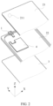
- FIG. 1 is a schematic diagram of a structure of an electronic device according to an embodiment of this application.
- FIG. 2 is a partial exploded view of FIG. 1 .
- a mobile phone is used as an example to describe an electronic device 100 in this application. It should be understood that the electronic device 100 in this embodiment includes but is not limited to a mobile phone.
- the electronic device 100 may alternatively be a mobile terminal such as the tablet computer, the notebook computer, the PDA, the smart wearable device, or the POS.
- the electronic device 100 may include a housing 2, a display panel 3, a camera module 1, and a circuit board 4.
- the housing 2 surrounds the back and the side of the electronic device 100, and the display panel 3 is mounted on the housing 2.
- the display panel 3 and the housing 2 jointly enclose accommodating space of the electronic device 100, and both the camera module 1 and the circuit board 4 are mounted in the accommodating space.
- a device such as a microphone, a speaker, or a battery may be further disposed in the accommodating space.
- FIG. 1 shows that the camera module 1 is located in an area at the top of the housing 2 near an edge. It may be understood that a position of the camera module 1 is not limited to the position shown in FIG. 1 .
- the housing 2 may include a back cover 21 and a middle frame 22.
- a light-transmitting hole 211 is disposed on the back cover 21, the camera module 1 may be disposed on the middle frame 22, and the camera module 1 collects external ambient light by using the light-transmitting hole 211 on the back cover 21.
- a photosensitive surface of the camera module 1 is opposite to the light-transmitting hole 211, and the external ambient light passes through the light-transmitting hole 211 and irradiates on the photosensitive surface. The photosensitive surface is used to collect the external ambient light.
- the camera module 1 is configured to convert an optical signal into an electrical signal to implement a photographing function thereof.
- FIG. 2 shows that one camera module 1 is disposed in the electronic device 100.
- a quantity of camera modules 1 is not limited to one, and the quantity of camera modules 1 may be two or more.
- the plurality of camera modules 1 may be randomly disposed in an X-Y plane.
- the plurality of camera modules 1 are disposed in an X-axis direction, or the plurality of camera modules 1 are disposed in a Y-axis direction.
- the camera module 1 includes but is not limited to an autofocus (Auto Focus, AF) module, a fixed-focus (Fix Focus, FF) module, a wide-angle camera module 1, a long-focus camera module 1, a color camera module 1, or a black-and-white camera module 1.
- the camera module 1 in the electronic device 100 may include any one of the foregoing camera modules 1, or include two or more of the foregoing camera modules 1. When there are two or more camera modules 1, the two or more camera modules 1 may be integrated into one camera assembly.
- the camera module 1 may be electrically connected to the circuit board 4.
- the circuit board 4 is, for example, a main board in the electronic device 100.
- the camera module 1 may be electrically connected to the main board by using an electrical connector.
- the camera module 1 is provided with a female socket of the electrical connector
- the main board is provided with a male socket of the electrical connector
- the female socket is inserted into the male socket, to electrically connect the camera module 1 to the main board.
- the main board is provided with a processor, and the processor controls the camera module 1 to photograph an image.
- the processor receives the photographing instruction, and controls, based on the photographing instruction, the camera module 1 to photograph a photographed object.
- the following describes in detail the camera module 1 in the electronic device 100 in this embodiment of this application.
- FIG. 3 is a schematic diagram of a structure of a camera module according to an embodiment of this application.
- FIG. 4 is an exploded view of FIG. 3 .
- the camera module 1 in this embodiment includes a casing 11, a lens assembly 13, and an image sensor component 16.
- a mounting hole 1111 is disposed on one side surface of the casing 11.
- An interior of the casing 11 is hollow to form accommodating space.
- the lens assembly 13 is mounted on the casing 11 by using the mounting hole 1111.
- One part of the lens assembly 13 is located in the accommodating space in the casing 11, and the other part of the lens assembly 13 is exposed outside the casing 11.
- the image sensor component 16 is disposed in the casing 11.
- the image sensor component 16 is disposed at the bottom of the casing 11.
- FIG. 5 is a main view of FIG. 3 .
- FIG. 6 is a sectional view along A-A in FIG. 5 .
- a light entry side of the lens assembly 13 is located outside the casing 11, and a light exit side of the lens assembly 13 is located inside the casing 11.
- the light entry side of the lens assembly 13 corresponds to the light-transmitting hole 211 on the back cover 21 of the electronic device 100.
- External ambient light passes through the light-transmitting hole 211, and enters the lens assembly 13 from the light entry side of the lens assembly 13.
- the lens assembly 13 includes, for example, one or more stacked lenses. An optical axis of the lens assembly 13 passes through the center of the lens, the lens converges incident light, and the converged light is emitted from the light exit side of the lens assembly 13.
- the image sensor component 16 is located on a light exit path of the lens assembly 13.
- the image sensor component 16 is located on the light exit side of the lens assembly 13, and the optical axis of the lens assembly 13 passes through the center of the image sensor component 16.
- Light emitted from the lens assembly 13 enters the image sensor component 16, and a signal of the emitted light is converted into an electrical signal by using photoelectric conversion action of the image sensor component 16, to implement an imaging function of the camera module 1.
- the casing 11 may include an outer frame 111 and a bottom plate 112, and the outer frame 111 and the bottom plate 112 jointly enclose accommodating space of the casing 11.
- the detachable bottom plate 112 is disposed, to help mount the lens assembly 13, the image sensor component 16, and another device of the camera module 1 in the casing 11.
- the mounting hole 1111 is located on a side surface that is of the outer frame 111 and that is opposite to the bottom plate 112.
- the lens assembly 13 is mounted in the casing 11 through the mounting hole 1111 in a direction of the optical axis of the lens assembly 13.
- the image sensor component 16 is close to the bottom plate 112.
- the camera module 1 in this embodiment further includes a first driving component 14 and a second driving component 15, and the first driving component 14 and the second driving component 15 are disposed in the casing 11.
- the first driving component 14 is configured to drive the image sensor component 16 to move.
- the first driving component 14 may drive the image sensor component 16 to translate or rotate in a direction perpendicular to the optical axis of the lens assembly 13 in a plane in which the image sensor component 16 is located, to implement an image stabilization function of the camera module 1.
- the second driving component 15 is configured to drive the lens assembly 13 to move.
- the second driving component 15 may drive the lens assembly 13 to move in the direction of the optical axis of the lens assembly 13, to implement a focusing function of the camera module 1.
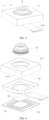
- FIG. 7 is a schematic diagram of an internal structure of a camera module according to an embodiment of this application.
- FIG. 8 is an exploded view of FIG. 7 .
- the fastening bracket 12 is sleeved outside the lens assembly 13.
- the fastening bracket 12 includes a first fastening part 121 and a second fastening part 122.
- One end of the second fastening part 122 is connected to a side that is of the first fastening part 121 and that faces the bottom of the casing 11, and the other end of the second fastening part 122 is supported on an inner bottom wall of the casing 11.
- the first fastening part 121 is, for example, an annular part surrounding an outer side of the lens assembly 13. At least one magnetic component 17 is fastened to an inner edge that is of the first fastening part 121 and that is close to an outer side wall of the lens assembly 13. The magnetic component 17 is configured to drive the first driving component 14 and the second driving component 15 to move.
- the first driving component 14 is located on the side that is of the first fastening part 121 and that faces the bottom of the casing 11, and one side surface of the first driving component 14 faces one part of the magnetic component 17.
- one part of the magnetic component 17 faces the bottom plate 112 of the casing 11, and the first driving component 14 faces the part of the magnetic component 17.
- the other side surface of the first driving component 14 is connected to the image sensor component 16.
- the first driving component 14 may generate a magnetic field, and a magnetic force may be generated between the first driving component 14 and the magnetic component 17.
- the first driving component 14 may be driven to move by changing the magnetic force between the first driving component 14 and the magnetic component 17.
- the first driving component 14 and the magnetic component 17 may be disposed in the direction of the optical axis of the lens assembly 13.
- a plate surface of the first driving component 14 is perpendicular to the direction of the optical axis of the lens assembly 13.
- the first driving component 14 is driven to move in the direction perpendicular to the optical axis of the lens assembly 13 by changing a magnitude of the magnetic force between the first driving component 14 and the magnetic component 17.
- the first driving component 14 translates or rotates in a plane in which the first driving component 14 is located, to drive the image sensor component 16 to translate or rotate, compensate for a displacement amount caused by hand shake of the user, prevent a captured image from being blurred, improve image definition, and improve quality of the image captured by the camera module 1.
- the second driving component 15 is sleeved outside the lens assembly 13.
- the second driving component 15 is fastened to an outer wall of the lens assembly 13, and the second driving component 15 may move to drive the lens assembly 13 to move.
- the second driving component 15 is located on an inner side of the inner edge of the first fastening part 121, and the second driving component 15 faces the other part of the magnetic component 17.
- the other part of the magnetic component 17 faces the outer wall of the lens assembly 13, and the second driving component 15 faces the part of the magnetic component 17.
- the second driving component 15 may generate a magnetic field, and a magnetic force may be generated between the second driving component 15 and the magnetic component 17.
- the second driving component 15 may be driven to move by changing the magnetic force between the second driving component 15 and the magnetic component 17.
- the magnetic component 17 may drive the second driving component 15 to move in the direction of the optical axis of the lens assembly 13, and the second driving component 15 drives the lens assembly 13 to move in the direction of the optical axis of the lens assembly 13, to adjust a focal length of the lens assembly 13.
- the fastening bracket 12 is supported on the bottom of the casing 11 by using the second fastening part 122.
- the second fastening part 122 defines space between the first fastening part 121 and the inner bottom wall of the casing 11, and the space is at least used to accommodate the first driving component 14 and the image sensor component 16.
- the second fastening part 122 may include a plurality of support parts 1221 disposed at intervals, each support part 1221 is connected to the side surface that is of the first fastening part 121 and that faces the bottom of the casing 11, and the first driving component 14 and the image sensor component 16 are located in space enclosed by the support parts 1221.
- FIG. 8 an example in which a contour of an outer edge of the first fastening part 121 is a rectangular structure is used.
- the magnetic component 17 is fixedly connected to the inner edge of the first fastening part 121, the first driving component 14 is movably connected to the side that is of the first fastening part 121 and that faces the bottom of the casing 11, and the image sensor component 16 is fixedly connected to the first driving component 14.
- An example in which the first driving component 14 translates or rotates in the plane in which the first driving component 14 is located is used.
- the image sensor component 16 translates or rotates with the first driving component 14. There should be a gap between the image sensor component 16 and the inner bottom wall of the casing 11, to prevent movement of the image sensor component 16 from being impeded by the inner bottom wall of the casing 11.
- At least two magnetic components 17 may be fastened to the inner edge of the first fastening part 121.
- Two magnetic components 17 are used as an example.
- the two magnetic components 17 may be disposed on two opposite sides of the first fastening part 121.
- the first driving component 14 and the second driving component 15 are driven to move by using the two magnetic components 17, so that a driving force of the magnetic components 17 on the first driving component 14 and the second driving component 15 can be enhanced.
- the two magnetic components 17 are opposite, so that it can be ensured that the first driving component 14 drives the image sensor component 16 to move smoothly, and the second driving component 15 drives the lens assembly 13 to move smoothly, thereby avoiding deflection of the image sensor 161 and the lens assembly 13 in a movement process.
- a quantity of magnetic components 17 that are fastened to the inner edge of the first fastening part 121 may be four, six, eight, or the like. This is not limited in this embodiment.
- a plurality of magnetic components 17 are opposite to each other in pairs.
- the housing 2 of the camera module 1 may be, for example, in a shape of a cuboid.
- a cross-sectional shape of the housing 2 in a direction perpendicular to an axial direction of the lens assembly 13 is a rectangle.
- the first fastening part 121 that is of the fastening bracket 12 and that matches a shape of the casing 11 may be a rectangular frame structure, and the lens assembly 13 partially penetrates an area surrounded by the rectangular frame.
- An example in which two or four magnetic components 17 that are opposite to each other in pairs are disposed on the inner edge of the first fastening part 121 is used.
- a contour of an inner edge of the rectangular frame may be a rectangle. If six or eight magnetic components 17 that are opposite to each other in pairs are disposed on the inner edge of the first fastening part 121, the contour of the inner edge of the rectangular frame may be correspondingly a hexagon or octagon.
- the magnetic component 17 is disposed on the fastening bracket 12, the magnetic component 17 is fastened to the inner edge of the first fastening part 121, the first driving component 14 and the image sensor component 16 are located in the space enclosed by the second fastening part 122, a part that is of the magnetic component 17 and that faces the first driving component 14 drives the first driving component 14 to move, the second driving component 15 is sleeved on the outer wall of the lens assembly 13, and a part that is of the magnetic component 17 and that faces the second driving component 15 drives the second driving component 15 to move.
- the first driving component 14 and the second driving component 15 may be synchronously manufactured and tested for performance. This can accurately test image stabilization performance of the camera module 1, thereby improving reliability of the camera module 1.
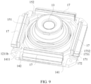
- FIG. 9 is a schematic diagram of a structure obtained after a fastening bracket is removed in FIG. 7 .
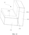
- FIG. 10 is a schematic diagram of a structure of a magnetic component according to an embodiment of this application.
- the magnetic component 17 includes a first magnetic member 171 and a second magnetic member 172.
- the first magnetic member 171 faces the first driving component 14, and the second magnetic member 172 faces the second driving component 15.
- the first magnetic member 171 is configured to drive the first driving component 14 to move, and the second magnetic member 172 is configured to drive the second driving component 15 to move.
- the first magnetic member 171 is fastened to a side surface that is of the first fastening part 121 and that faces the first driving component 14, and the first magnetic member 171 faces a surface of the first driving component 14.
- the second magnetic member 172 is fastened to a side surface that is of the first fastening part 121 and that faces the second driving component 15, and the second magnetic member 172 faces a surface of the second driving component 15.
- the first magnetic member 171 may be disposed in the direction perpendicular to the optical axis of the lens assembly 13
- the second magnetic member 172 may be disposed in the direction of the optical axis of the lens assembly 13
- the first magnetic member 171 and the second magnetic member 172 are perpendicular to each other.
- the first driving component 14 includes a support plate 141 and a first driving coil 142.
- a plate surface of the support plate 141 may be perpendicular to the optical axis of the lens assembly 13.
- the first driving coil 142 is disposed on a surface that is of the support plate 141 and that faces the first magnetic member 171.
- the image sensor component 16 is connected to the other side surface of the support plate 141.
- the first driving coil 142 corresponds to the first magnetic member 171.
- the first driving coil 142 is fastened to the support plate 141.
- the first driving coil 142 may be adhered or welded to the support plate 141, or the first driving coil 142 is locked to the support plate 141 by using a connecting piece such as a bolt or a screw.
- the first driving coil 142 may be provided with a lightening hole 1421. This facilitates movement of the first driving component 14.
- the first driving component 14 may be connected to an external circuit, for example, the first driving component 14 is electrically connected to the circuit board 4 in the electronic device 100.
- the circuit board 4 controls the first driving component 14 to work.
- the first driving coil 142 is energized to generate an electromagnetic field, and a magnetic force is generated between the first driving coil 142 and the first magnetic member 171.
- the magnetic force drives the first driving coil 142 to move.
- the first driving coil 142 drives the image sensor component 16 to move by using the support plate 141.
- an acceleration sensor is usually further disposed in the electronic device 100, and a movement direction and a movement amount of the electronic device 100 are detected by using the acceleration sensor.
- the acceleration sensor detects a hand shake direction and a shake amount of the user during photographing, and the acceleration sensor transmits the shake signal to a processor in the circuit board 4.
- the processor determines, based on the shake signal, a movement direction and a movement amount required by the image sensor component 16 for compensation, controls a direction and a magnitude of a current in the first driving coil 142, and adjusts a direction of the magnetic field and a magnitude of the magnetic force that are generated between the first driving coil 142 and the first magnetic member 171, to control a movement direction and a movement amount of the first driving component 14.
- the first driving component 14 drives the image sensor component 16 to move.
- the first driving component 14 drives the image sensor component 16 to translate or rotate in the plane in which the image sensor component 16 is located, to compensate for interference caused by hand shake of the user during photographing, improve a blurring phenomenon of an image, and improve image quality.
- the second driving component 15 includes a support base 151 and a second driving coil 152.
- the support base 151 is sleeved on the outer wall of the lens assembly 13, and is configured to support the lens assembly 13.
- the outer wall of the lens assembly 13 may be provided with an external thread
- an inner wall of the support base 151 is provided with an internal thread
- the support base 151 is thread-connected to the outer wall of the lens assembly 13.
- the second driving coil 152 is sleeved on an outer wall of the support base 151, and the second driving coil 152 is fixedly connected to the support base 151.
- the second driving component 15 may be electrically connected to the circuit board 4 in the electronic device 100.
- the circuit board 4 controls the second driving component 15 to work.
- the second driving coil 152 is energized to generate an electromagnetic field, and a magnetic force is generated between the second driving coil 152 and the second magnetic member 172.
- the magnetic force drives the second driving coil 152 to move.
- the second driving coil 152 drives the lens assembly 13 to move by using the support base 151.
- the user inputs a photographing instruction when photographing an image.
- the user inputs a focusing instruction by operating a display interface of the electronic device 100.
- the circuit board 4 in the electronic device 100 receives the focusing instruction, controls a direction and a magnitude of a current in the second driving coil 152, and adjusts a direction of the magnetic field and a magnitude of the magnetic force that are generated between the second driving coil 152 and the second magnetic member 172, to control a movement direction and a movement amount of the second driving component 15.
- the second driving component 15 drives the lens assembly 13 to move.
- the second driving component 15 drives the lens assembly 13 to move in the direction of the optical axis of the lens assembly 13, to perform focusing on a photographed object.
- an area that is on a surface of the second driving coil 152 and that is opposite to the second magnetic member 172 may be parallel to a surface of the second magnetic member 172.
- An example in which four second magnetic members 172 are evenly disposed at intervals in a circumferential direction of the inner edge of the first fastening part 121 is used.
- the second driving coil 152 may be approximately a rectangular coil, and each side of the second driving coil 152 corresponds to the second magnetic member 172.
- the second driving coil 152 is substantially a hexagonal or octagonal coil.
- the outer wall of the lens assembly 13 is usually a cylindrical surface. Therefore, the support base 151 may be a circular structural member.
- the second driving coil 152 is a rectangular coil, a hexagonal coil, an octagonal coil, or the like, some areas on an inner wall of the second driving coil 152 may be fastened to the outer wall of the support base 151. For example, these areas of the second driving coil 152 are adhered or welded to the outer wall of the support base 151.
- the first magnetic member 171 and the second magnetic member 172 may be fastened to the first fastening part 121.
- the first magnetic member 171 is fastened to the side surface that is of the first fastening part 121 and that faces the first driving component 14
- the second magnetic member 172 is fastened to the side surface that is of the first fastening part 121 and that faces the second driving component 15.
- the first magnetic member 171 and the second magnetic member 172 may be adhered to a surface of the first fastening part 121.
- the magnetic component 17 may further include a magnetoconductive member 173.
- the magnetoconductive member 173 is fastened to the first fastening part 121, and the first magnetic member 171 and the second magnetic member 172 are fastened by using the magnetoconductive member 173.
- the magnetoconductive member 173 includes a first magnetoconductive part 1731 and a second magnetoconductive part 1732.
- the first magnetoconductive part 1731 faces the first driving component 14
- the second magnetoconductive part 1732 faces the second driving component 15
- the first magnetic member 171 is fastened to the first magnetoconductive part 1731
- the second magnetic member 172 is fastened to the second magnetoconductive part 1732.
- first magnetic member 171 and the second magnetic member 172 are perpendicular to each other.
- the first magnetoconductive part 1731 and the second magnetoconductive part 1732 of the magnetoconductive member 173 may be perpendicular to each other.
- Magnetic poles of the first magnetoconductive part 1731 and the second magnetoconductive part 1732 are opposite to each other.
- the first magnetoconductive part 1731 is a north pole (N pole)
- the second magnetoconductive part 1732 is a south pole (S pole); or the first magnetoconductive part 1731 is an S pole, and the second magnetoconductive part 1732 is an N pole.
- the surface of the first magnetic member 171 is attached to a surface of the first magnetoconductive part 1731, and the surface of the second magnetic member 172 is attached to a surface of the second magnetoconductive part 1732.
- the first magnetic member 171 may be absorbed to the surface of the first magnetoconductive part 1731 by using magnetic adsorption action, and the second magnetic member 172 may also be adsorbed to the surface of the second magnetoconductive part 1732 by using magnetic adsorption action.
- the first magnetoconductive part 1731 is an N pole
- a side that is of the first magnetic member 171 and that is adsorbed to the first magnetoconductive part 1731 is an S pole
- a side that is of the first magnetic member 171 and that faces the first driving component 14 is an N pole
- the second magnetoconductive part 1732 is an S pole
- a side that is of the second magnetic member 172 and that is adsorbed to the second magnetoconductive part 1732 is an N pole
- a side that is of the second magnetoconductive member 173 and that faces the second driving component 15 is an S pole.
- the first magnetoconductive part 1731 is an S pole
- a side that is of the first magnetic member 171 and that is adsorbed to the first magnetoconductive part 1731 is an N pole
- a side that is of the first magnetic member 171 and that faces the first driving component 14 is an S pole
- the second magnetoconductive part 1732 is an N pole
- a side that is of the second magnetic member 172 and that is adsorbed to the second magnetoconductive part 1732 is an S pole
- a side that is of the second magnetoconductive member 173 and that faces the second driving component 15 is an N pole.
- the first magnetic member 171 and the second magnetic member 172 may be further connected to each other by using an adhesive.
- both the first magnetic member 171 and the second magnetic member 172 are adhered to the magnetoconductive member 173 by using a strong adhesive.
- the magnetoconductive member 173 may be adhered or welded to the first fastening part 121. Specifically, as shown in FIG. 6 , a side wall that is of the first fastening part 121 and that faces the lens assembly 13 and a side wall that is of the first fastening part 121 and that faces the bottom of the casing 11 may be perpendicular to each other, the surface of the first magnetoconductive part 1731 of the magnetoconductive member 173 is attached to the surface that is of the first fastening part 121 and that faces the bottom of the casing 11, and the surface of the second magnetoconductive part 1732 of the magnetoconductive member 173 is attached to the side wall that is of the first fastening part 121 and that faces the lens assembly 13.
- FIG. 11 is a schematic diagram of a structure of a fastening bracket according to an embodiment of this application.
- a positioning plate 123 may be further disposed on the fastening bracket 12, and the positioning plate 123 has a strengthening effect on fastening of the magnetoconductive member 173, to ensure that the magnetoconductive member 173 and the first fastening part 121 are connected securely.
- the positioning plate 123 may be supported on a bending part of the magnetoconductive member 173, that is, the positioning plate 123 is located at a connection part between the first magnetoconductive part 1731 and the second magnetoconductive part 1732.
- the positioning plate 123 may include two parts perpendicular to each other, to match a structure of the connection part between the first magnetoconductive part 1731 and the second magnetoconductive part 1732.
- the positioning plate 123 There is a gap between the positioning plate 123 and the first fastening part 121.
- a width of the gap matches a thickness of the magnetoconductive member 173.
- One side of the magnetoconductive member 173 is attached to the first fastening part 121, and a bending part on the other side surface of the magnetoconductive member 173 is attached to the positioning plate 123.
- two ends of the positioning board 123 are respectively connected to support parts 1221 on two sides thereof.
- the first fastening part 121 has a structure for fastening the positioning plate 123, and two ends of the positioning plate 123 are fastened to the first fastening part 121.
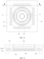
- FIG. 12 is a main view of FIG. 7 .
- FIG. 13 is a sectional view along B-B in FIG. 12 .
- the first driving component 14 and the first fastening part 121 are in contact with each other through rolling.
- a side surface that is of the support plate 141 and that faces the first fastening part 121 and the surface of the first fastening part 121 are in contact with each other through rolling, to ensure that the first driving component 14 smoothly moves in the plane on which the first driving component 14 is located.
- a first limiting part 1211 is disposed on the first fastening part 121
- a second limiting part 1411 is disposed on the surface that is of the support plate 141 and that faces the first fastening part 121
- the second limiting part 1411 is opposite to the first limiting part 1211
- a ball 1211b is disposed between the first limiting part 1211 and the second limiting part 1411
- the first limiting part 1211 and the second limiting part 1411 are in contact with each other by using the ball 1211b.
- the first limiting part 1211 may be a limiting boss located on a side surface that is of the first fastening part 121 and that faces the support plate 141
- the second limiting part 1411 may be a limiting boss on the support plate 141
- the limiting boss protrudes toward the first fastening part 121
- the ball 1211b is located between the first limiting part 1211 and the second limiting part 1411.
- the ball 1211b rolls between the first limiting part 1211 and the second limiting part 1411, and the support plate 141 and the first fastening part 121 are not in contact with each other, so that friction between the support plate 141 and the first fastening part 121 can be reduced, to ensure that the support plate 141 flexibly moves.
- At least one first limiting part 1211 is disposed on the first fastening part 121, and at least one second limiting part 1411 is disposed on the support plate 141.
- At least two first limiting parts 1211 are disposed on the first fastening part 121, and at least two second limiting parts 1411 are disposed on the support plate 141.
- first limiting parts 1211 and two second limiting parts 1411 are respectively disposed on the first fastening part 121 and the support plate 141 .
- the two first limiting parts 1211 may be respectively located on two opposite sides of the first fastening part 121.
- the two second limiting parts 1411 may be respectively located on two opposite sides of the support plate 141, to ensure balance between two sides of the support plate 141 and ensure stability of the support plate 141.
- a quantity of first limiting parts 1211 disposed on the first fastening part 121 is not limited to two, and the quantity of first limiting parts 1211 may be four, six, eight, or the like.
- a quantity of second limiting parts 1411 disposed on the support plate 141 is not limited to two, and the quantity of second limiting parts 1411 may be four, six, eight, or the like. Both the plurality of first limiting parts 1211 and the plurality of second limiting parts 1411 may be symmetrically disposed in pairs, to ensure balance of the support plate 141.
- a position of the ball 1211b may be shifted.
- a limiting recess 1211a may be disposed on one of the first limiting part 1211 and the second limiting part 1411, and the ball 1211b moves in the limiting recess 1211a.
- a limiting recess 1211a is disposed on a side surface that is of the first limiting part 1211 and that faces the second limiting part 1411, and the ball 1211b is located in the limiting recess 1211a and is in contact with a surface of the second limiting part 1411.
- An inner diameter of the limiting recess 1211a may match an outer diameter of the ball 1211b, the ball 1211b rotates in the limiting recess 1211a, and the position of the ball 1211b is fixed.
- an inner diameter of the limiting recess 1211a may be greater than an outer diameter of the ball 1211b, and the ball 1211b may rotate and move in the limiting recess 1211a.
- a diameter of the ball 1211b may be greater than a depth of the limiting recess 1211a, so that one part of the ball 1211b is located in the limiting recess 1211a, and the other part of the ball 1211b is exposed outside the limiting recess 1211a.
- the part that is of the ball 1211b and that is exposed outside the limiting recess 1211a is located between a surface of the first limiting part 1211 and the surface of the second limiting part 1411.
- the first driving component 14 is movably connected to the first fastening part 121 by using magnetic absorption action, and the ball 1211b is disposed between the first limiting part 1211 on the first fastening part 121 and the second limiting part 1411 on the support plate 141, so that there is a gap between the support plate 141 and the first fastening part 121, and the support plate 141 and the first fastening part 121 are in contact with each other through rolling.
- the support plate 141 may be a magnetoconductive plate.
- the first magnetic member 171 on the first fastening part 121 generates a magnetic attraction force for the support plate 141, so that not only a magnetic force exists between the first driving coil 142 and the first magnetic member 171, but also a magnetic force exists between the support plate 141 and the first magnetic member 171. Therefore, a magnetic attraction force between the first driving component 14 and the first magnetic member 171 can be enhanced, to ensure that the support plate 141 is always in contact with the first fastening part 121, and prevent the support plate 141 from loosening.
- the fastening bracket 12 may be an integrally formed part, the first fastening part 121 and the second fastening part 122 are a whole, and the second fastening part 122 is formed on the side that is of the first fastening part 121 and that faces the bottom of the casing 11.
- first fastening part 121 and the second fastening part 122 may be separately designed and processed, and the first fastening part 121 and the second fastening part 122 are connected together to form the fastening bracket 12.
- first fastening part 121 and the second fastening part 122 are adhered, welded, or connected by using a connecting piece such as a bolt, a screw, or a rivet. Therefore, the first fastening part 121 may be an annular member, and the second fastening part 122 may include a plurality of separate support parts 1221.
- the second fastening part 122 includes an annular part as a main body, the annular part matches the first fastening part 121, the annular part is attached and connected to the first fastening part 121, and each support part 1221 is connected to the annular part.
- the first limiting part 1211 located on the fastening bracket 12 may be formed on the first fastening part 121 or the second fastening part 122.
- the image sensor component 16 includes an image sensor 161 and a flexible electrical connecting piece 162.
- the image sensor 161 is located on the light exit side of the lens assembly 13, for example, the optical axis of the lens assembly 13 passes through the center of the image sensor 161.
- Light emitted from the lens assembly 13 irradiates on the image sensor 161, and the image sensor 161 converts a signal of the emitted light into an electrical signal through photoelectric conversion, to implement an imaging function of the camera module 1.
- the flexible electrical connecting piece 162 is configured to electrically connect the image sensor 161 to an external circuit, to control image sensing working by using the external circuit. Specifically, one end of the flexible electrical connecting piece 162 is connected to the image sensor 161, and the other end of the flexible electrical connecting piece 162 is connected to the external circuit. For example, the other end of the flexible electrical connecting piece 162 is connected to the circuit board 4 in the electronic device 100. When the user performs photographing, the processor in the circuit board 4 controls the image sensor 161 to work.
- the image sensor 161 generates heat in a working process, and the heat is accumulated on the image sensor 161. As a result, performance of the image sensor 161 may be affected, and the image sensor 161 cannot work normally in a severe case. Therefore, heat dissipation needs to be performed on the image sensor 161. In the related technology, heat dissipation is performed on the image sensor 161 by using an air gap between the image sensor 161 and the bottom of the casing 11, and heat dissipation efficiency is low. As a result, the image sensor 161 cannot work in a high power consumption mode for a long time. For example, 5 minutes after the user starts a camera on the electronic device 100, the image sensor 161 enters a thermal protection mode, and stops working.
- FIG. 14 is an exploded view in which an image sensor is in contact with a bottom plate according to an embodiment of this application.
- a heat dissipation surface a side surface that is of the image sensor 161 and that faces the inner bottom wall of the casing 11
- the gap is filled with a thermally conductive liquid 18, and heat dissipation is performed on the image sensor 161 by using the heat transfer liquid 18.
- Heat of the heat dissipation surface of the image sensor 161 is transferred to the thermally conductive liquid 18 by using thermal conduction action, and the thermally conductive liquid 18 conducts the heat to the bottom plate 112, to dissipate the heat to the outside by using the bottom plate 112, so as to dissipate heat for the image sensor 161.
- heat dissipation efficiency of the image sensor 161 can be improved, and a heat dissipation effect of the image sensor 161 can be improved, thereby ensuring working performance of the image sensor 161.
- an annular sealing plate 19 is affixed to the bottom plate 112 of the casing 11, and the thermally conductive liquid 18 is located in an area enclosed by the annular sealing plate 19.
- the thermally conductive liquid 18 is flowable liquid, and the annular sealing plate 19 is disposed on the bottom plate 112 of the casing 11, so that the thermally conductive liquid 18 is limited in the area enclosed by the annular sealing plate 19.
- the area enclosed by the annular sealing plate 19 may correspond to the heat dissipation surface of the image sensor 161. In this way, an area in which the thermally conductive liquid 18 is located corresponds to the heat dissipation surface of the image sensor 161, to ensure a thermal conduction effect of the thermally conductive liquid 18 on the image sensor 161.
- thermally conductive liquid 18 To enable the thermally conductive liquid 18 to be fully in contact with the heat dissipation surface of the image sensor 161, there may be a gap between the annular sealing plate 19 and the heat dissipation surface of the image sensor 161, and a liquid surface of the thermally conductive liquid 18 may be higher than a surface of the annular sealing plate 19. It should be noted that, because the gap between the annular sealing plate 19 and the image sensor 161 is very small, based on surface tension action of the thermally conductive liquid 18 in the gap, the thermally conductive liquid 18 can be prevented from spilling out of the annular sealing plate 19.
- the thermally conductive liquid 18 absorbs heat of the image sensor 161, a temperature thereof increases, and a volume of the thermally conductive liquid 18 expands to a specific extent. As a result, the thermally conductive liquid 18 spills out.
- the gap between the annular sealing plate 19 and the image sensor 161 may accommodate an expansion amount of the thermally conductive liquid 18.
- the thermally conductive liquid 18 may be limited in an area in which the annular sealing plate 19 is located, to prevent the thermally conductive liquid 18 from spilling out of the annular sealing plate 19 and affecting another device of the camera module 1.
- a plurality of sealing holes 191 may be disposed at intervals on the annular sealing plate 19.
- the plurality of sealing holes 191 are disposed. In this way, when the thermally conductive liquid 18 spills out along the surface of the annular sealing plate 19, the thermally conductive liquid 18 enters each sealing hole 191, and the thermally conductive liquid 18 is sealed and stored by using the sealing hole 191, to prevent the thermally conductive liquid 18 from spilling out of the annular sealing plate 19.
- the surface of the annular sealing plate 19 may be an uneven corrugated surface.
- a recessed area between two adjacent protrusions of the corrugated surface is used to store the thermally conductive liquid 18.
- a gap is formed between the top of a raised area of the corrugated surface and the image sensor 161. Based on surface tension action of the thermally conductive liquid 18 in the gap, the thermally conductive liquid 18 can be prevented from diffusing outward. Therefore, the corrugated surface can prevent the thermally conductive liquid 18 from spilling out of the annular sealing plate 19.
- a stop edge may be disposed on an outer edge of the annular sealing plate 19, and a height of the stop edge is greater than a thickness of the recessed area of the corrugated surface.
- the stop edge is flush with the top of the raised area of the corrugated surface.
- a corrugation extension direction (extension directions of the raised area and the recessed area) of the corrugated surface may be consistent with an extension direction of each side of the annular sealing plate 19.
- An example in which the annular sealing plate 19 is a rectangular frame structure is used.
- a corrugation extension direction of a corrugated surface on one side of the annular sealing plate 19 is consistent with an extension direction of the side. In this way, when spilling out, the thermally conductive liquid 18 needs to cross a protrusion on the corrugated surface to reach an adj acent recessed area, so that the corrugated surface can effectively prevent the thermally conductive liquid 18 from spilling out.
- FIG. 15 is a schematic diagram of a structure of an annular sealing plate according to an embodiment of this application.
- a plurality of strip-shaped grooves 192 may be disposed at intervals on the surface of the annular sealing plate 19, and extend in a direction of a contour line of the annular sealing plate 19.
- An example in which a contour of the annular sealing plate 19 is a rectangular frame is used.
- the strip-shaped groove 192 may extend in a direction of an edge length of the annular sealing plate 19.
- the strip-shaped groove 192 located at a corner of the annular sealing plate 19 may extend in a direction of two sides.
- the strip-shaped groove 192 located at the corner of the annular sealing plate 19 is a vertically curved strip-shaped groove 192.
- the strip-shaped groove 192 may store the thermally conductive liquid 18.
- the strip-shaped groove 192 prevents the thermally conductive liquid 18 from spilling out.
- the strip-shaped grooves 192 are disposed at intervals on the surface of the annular sealing plate 19, and adjacent strip-shaped grooves 192 do not communicate with each other. This has small impact on strength of the annular sealing plate 19, and can prevent the annular sealing plate 19 from being bent or even broken.
- an example in which the annular sealing plate 19 is bent along a line a in FIG. 15 is used. Because extension directions of strip-shaped grooves 192 at two ends of a bending part are perpendicular to an extension direction of a strip-shaped grooves 192 in the middle, strength of the annular sealing plate 19 is enhanced.
- a plurality of rows of strip-shaped grooves 192 may be disposed at intervals from an inner edge to an outer edge of the annular sealing plate 19, and strip-shaped grooves 192 in different rows are staggered. In this way, in a direction from the inner edge to the outer edge of the annular sealing plate 19, intervals formed between adjacent strip-shaped grooves 192 are also staggered back and forth.
- the thermally conductive liquid 18 in a strip-shaped groove 192 close to the inner edge spills out, the thermally conductive liquid 18 spills from an end part of the strip-shaped groove 192 to be stored in a strip-shaped groove 192 close to the outer edge, to prevent the thermally conductive liquid 18 from spilling out.
- the annular sealing plate 19 may be a rubber plate or a silicone plate.
- the annular sealing plate 19 is a porous rubber plate or a porous silicone plate.
- FIG. 16 is a schematic diagram of a structure of an image sensor component according to an embodiment of this application.
- the flexible electrical connecting piece 162 connected to the image sensor 161 may include a connecting part 1621, a movable cantilever 1622, and a mounting part 1623.
- the connecting part 1621 is connected to the image sensor 161
- the mounting part 1623 is connected to an external circuit (for example, the circuit board 4 of the electronic device 100)
- the movable cantilever 1622 is located between the connecting part 1621 and the mounting part 1623.
- the connecting part 1621 is connected to a side surface of the image sensor 161, the movable cantilever 1622 extends around the image sensor 161, the movable cantilever 1622 is located inside the casing 11 of the camera module 1, one end of the mounting part 1623 is connected to the movable cantilever 1622, the mounting part 1623 extends out of the casing 11, the mounting part 1623 extends toward the circuit board 4, and the other end of the mounting part 1623 is connected to the circuit board 4.
- an end part of the mounting part 1623 is connected to the circuit board 4 by using an electrical connector.
- the movable cantilever 1622 is a movable part of the flexible electrical connecting piece 162.
- the movable cantilever 1622 correspondingly deforms and moves, to prevent the flexible electrical connecting piece 162 from limiting movement of the image sensor 161.
- the movable cantilever 1622 may surround the image sensor 161 at least half a circle.
- the connecting part 1621 is connected to a side edge on one side of the image sensor 161
- the movable cantilever 1622 surrounds the image sensor 161 from the side edge connected to the connecting part 1621, and extends to an adjacent side edge.
- the movable cantilever 1622 includes at least two parts that extend in different directions, and the movable cantilever 1622 can enable the image sensor 161 to move in any direction in the plane in which the image sensor 161 is located.
- the movable cantilever 1622 may surround the image sensor 161 one circle. With the flexible electrical connecting piece 162 as a whole, after the flexible electrical connecting piece 162 surrounds the image sensor 161 one circle from an end that is of the flexible electrical connecting piece 162 and that is connected to the image sensor 161, the flexible electrical connecting piece 162 extends out of the casing 11. In this way, the movable cantilever 1622 may provide sufficient freedom for the image sensor 161, so that movement of the image sensor 161 is not limited. It should be noted that the movable cantilever 1622 is an elastic cantilever, and after being deformed, the movable cantilever 1622 may be restored to an initial shape, to provide a reliable guarantee for movement of the image sensor 161.
- the connecting part 1621 of the flexible electrical connecting piece 162 may be level with the surface of the image sensor 161, and the movable cantilever 1622 is perpendicular to the surface of the image sensor 161. In this way, the movable cantilever 1622 easily deforms and moves. Because the mounting part 1623 extends out of the casing 11 and is connected to the circuit board 4, the mounting part 1623 may be attached to an inner wall of the rear cover 21 of the electronic device 100. The mounting part 1623 is also level with the surface of the image sensor 161.
- the image sensor component 16 may further include a light-transmitting plate 163.
- the light-transmitting plate 163 may be a transparent protection plate, and the light-transmitting plate 163 is configured to protect the image sensor 161 from damage.
- the light-transmitting plate 163 may be a filter plate, and the light-transmitting plate 163 is configured to filter out light of a specific wavelength.
- the light-transmitting plate 163 is configured to filter out invisible light, for example, filter out an infrared ray or an ultraviolet ray.
- the fastening bracket 12 is disposed in the casing 11, the fastening bracket 12 includes the first fastening part 121 and the second fastening part 122, the first fastening part 121 is sleeved outside the lens assembly 13, one end of the second fastening part 122 is connected to the side that is of the first fastening part 121 and that faces the bottom of the casing 11, the other end of the second fastening part 122 is supported on the bottom of the casing 11, the magnetic component 17 is disposed on the inner edge of the first fastening part 121, a part that is of the magnetic component 17 and that faces the first driving component 14 is configured to drive the first driving component 14 to move, a part that is of the magnetic component 17 and that faces the second driving component 15 is configured to drive the second driving component 15 to move, and the image sensor component 16 and the lens assembly 13 are respectively driven to move by using the first driving component 14 and the second driving component 15.
- the first driving component 14 and the second driving component 15 are driven by using the magnetic component 17 disposed on the fastening bracket 12. Therefore, a structure of the camera module 1 is simplified, an assembly process of the camera module 1 is simple, and it is easy to test performance of the camera module 1, thereby improving reliability of the camera module 1.
- An embodiment further provides an assembly method for a camera module, and the assembly method is used to assemble the camera module 1 described above. Specifically, the assembly method includes the following steps.
- a lens assembly 13 is provided, and a second driving component 15 is sleeved on an outer wall of the lens assembly 13.
- a fastening bracket 12 is provided, where the fastening bracket 12 includes a first fastening part 121 and a second fastening part 122, and the second fastening part 122 is connected to a bottom surface of the first fastening part 121; and at least one magnetic component 17 is fastened to an inner edge of the first fastening part 121.
- a first driving component 14 is provided.
- the step of sleeving the second driving component 15 on the lens assembly 13 and the step of fastening the magnetic component 17 to the fastening bracket 12 may be successively and separately performed.
- a sequence between the process of providing the first driving component 14, the assembly process of the lens assembly 13 and the second driving component 15, and the assembly process of the fastening bracket 12 and the magnetic component 17 is not limited in this embodiment.
- the first driving component 14 and the second driving component 15 may be synchronously manufactured.
- the fastening bracket 12 is sleeved outside the lens assembly 13, so that the second driving component 15 on an outer wall of the lens assembly 13 faces one part of the magnetic component 17 on the inner edge of the first fastening part 121.
- the first driving component 14 is connected to the fastening bracket 12, so that one side surface of the first driving component 14 faces the other part of the magnetic component 17.
- an image sensor component 16 is fastened to the other side surface of the first driving component 14.
- the casing 11 may include an outer frame 111 and a bottom plate 112, and the image sensor component 16 is supported on the bottom plate 112.
- the bottom plate 112 may be first mounted at the bottom of the image sensor component 16, and then the outer frame 111 is fixedly connected to the bottom plate 112.
- the image sensor component 16 is assembled on the first driving component 14.
- the image sensor component 16 may be separately processed and manufactured, so that production costs of the image sensor component 16 can be reduced.
- the terms “mount”, “communicate”, and “connect” should be understood in a broadest sense, for example, may be a fixed connection, an indirect connection by using an intermediate medium, or a connection between insides of two elements or an interaction relationship between the two elements.
- a person of ordinary skill in the art may understand specific meanings of the foregoing terms in the embodiments of this application based on a specific situation.
Landscapes
- Engineering & Computer Science (AREA)
- Signal Processing (AREA)
- Multimedia (AREA)
- Health & Medical Sciences (AREA)
- Biomedical Technology (AREA)
- General Health & Medical Sciences (AREA)
- Studio Devices (AREA)
- Lens Barrels (AREA)
Abstract
Description
- This application claims priority to
Chinese Patent Application No. 202110295108.8, filed on March 19, 2021 Chinese Patent Application No. 202110603417.7, filed on May 31, 2021 - This application relates to the field of mobile terminal technologies, and in particular, to a camera module, an assembly method therefor, and an electronic device.
- In life, people often use electronic devices (such as smartphones and tablet computers) for photographing. Quality of photos taken by the electronic devices has become one of important criteria for measuring performance of the terminal devices.
- When performing photographing by using a portable electronic device (such as a mobile phone), a user usually performs photographing in a handheld manner. Therefore, there is often a problem that a captured image is blurred due to hand shake. To resolve the problem, some electronic devices have an optical image stabilization function. A movement amount of hand shake is offset by moving a lens assembly or an image sensor of a camera module, to improve quality of a captured image.
- However, a current mainstream camera module has many parts and a complex assembly process, and it is difficult to test performance.
- This application provides a camera module, an assembly method therefor, and an electronic device, so that the camera module has a simple structure, is easy to assemble, and has high reliability.
- According to a first aspect, this application provides a camera module, including a casing, a fastening bracket, a lens assembly, a first driving component, a second driving component, and an image sensor component, where a mounting hole is disposed on one side surface of the casing, the lens assembly is partially accommodated in the casing by using the mounting hole, the fastening bracket is disposed in the casing, the image sensor component is located at the bottom of the casing, the fastening bracket includes a first fastening part and a second fastening part, the first fastening part is sleeved outside the lens assembly, one end of the second fastening part is connected to a side that is of the first fastening part and that faces the bottom of the casing, the other end of the second fastening part is supported on an inner bottom wall of the casing, and at least one magnetic component is fastened to an inner edge of the first fastening part; and
the first driving component is located on the side that is of the first fastening part and that faces the bottom of the casing, one side surface of the first driving component faces one part of the magnetic component, the other side surface of the first driving component is connected to the image sensor component, the magnetic component is configured to drive the first driving component to move, the second driving component is sleeved on an outer wall of the lens assembly, the second driving component faces the other part of the magnetic component, and the magnetic component is configured to drive the second driving component to move. - In the camera module provided in this application, the fastening bracket is disposed in the casing, the fastening bracket includes the first fastening part and the second fastening part, the first fastening part is sleeved outside the lens assembly, one end of the second fastening part is connected to the side that is of the first fastening part and that faces the bottom of the casing, the other end of the second fastening part is supported on the bottom of the casing, the magnetic component is disposed on the inner edge of the first fastening part, a part that is of the magnetic component and that faces the first driving component is configured to drive the first driving component to move, a part that is of the magnetic component and that faces the second driving component is configured to drive the second driving component to move, and the image sensor component and the lens assembly are respectively driven to move by using the first driving component and the second driving component. The first driving component and the second driving component are driven by using the magnetic component disposed on the fastening bracket. Therefore, a structure of the camera module is simplified, an assembly process of the camera module is simple, and it is easy to test performance of the camera module, thereby improving reliability of the camera module.
- In a possible implementation, the second fastening part includes a plurality of support parts disposed at intervals, and the first driving component and the image sensor component are located in space enclosed by the plurality of support parts.
- In a possible implementation, at least two magnetic components are fastened to the inner edge of the first fastening part, and the two magnetic components are respectively disposed on two opposite sides of the first fastening part.
- At least two opposite magnetic components are disposed, and the first driving component and the second driving component are driven to move by using the magnetic components on two sides, so that movement of the image sensor component and the lens assembly is smoother.
- In a possible implementation, the magnetic component includes a first magnetic member and a second magnetic member, the first magnetic member faces the first driving component and drives the first driving component to move, and the second magnetic member faces the second driving component and drives the second driving component to move.
- The first magnetic member and the second magnetic member are disposed, so that the first driving component is driven to move by using a magnetic force generated between the first magnetic member and the first driving component, and the second driving component is driven to move by using a magnetic force generated between the second magnetic member and the second driving component.
- In a possible implementation, the magnetic component further includes a magnetoconductive member fastened to the first fastening part, the magnetoconductive member includes a first magnetoconductive part and a second magnetoconductive part, the first magnetoconductive part faces the first driving component, a surface of the first magnetic member is attached to a surface of the first magnetoconductive part, the second magnetoconductive part faces the second driving component, and a surface of the second magnetic member is attached to a surface of the second magnetoconductive part; and
the first magnetoconductive part and the second magnetoconductive part have opposite magnetism, the first magnetic member and the first magnetoconductive part have opposite magnetism, and the second magnetic member and the second magnetoconductive part have opposite magnetism. - The first magnetic member and the second magnetic member are fastened to the first fastening part by using the magnetoconductive member. The first magnetic member is fastened by using the first magnetoconductive part of the magnetoconductive member, and the first magnetoconductive part absorbs the first magnetic member to the surface of the first magnetoconductive part by using a magnetic attraction force between the first magnetoconductive part and the first magnetic member. The second magnetic member is fastened by using the second magnetoconductive part of the magnetoconductive member, and the second magnetoconductive part absorbs the second magnetic member to the surface of the second magnetoconductive part by using a magnetic attraction force between the second magnetoconductive part and the second magnetic member.
- In a possible implementation, the first driving component includes a support plate and at least one first driving coil, the first driving coil is disposed on a side surface that is of the support plate and that faces the magnetic component, and the first driving coil is opposite to the magnetic component.
- The support plate is disposed to fasten the first driving coil, a magnetic force is generated between the first driving coil and the magnetic component by enabling the first driving coil to face the magnetic component, and a magnitude and a direction of a current in the first driving coil are adjusted to change a magnitude and a direction of the magnetic force between the first driving coil and the magnetic component, thereby implementing movement of the first driving component.
- In a possible implementation, at least one first limiting part is disposed on the first fastening part, at least one second limiting part is disposed on a side that is of the support plate and that faces the first fastening part, the second limiting part is opposite to the first limiting part, a ball is disposed between the first limiting part and the second limiting part, and the first limiting part and the second limiting part are in contact with each other by using the ball.
- The first limiting part is disposed on the first fastening part, the second limiting part opposite to the first limiting part is disposed on the support plate, and the ball is disposed between the first limiting part and the second limiting part, so that the first fastening part and the support plate are in contact with each other through rolling, thereby reducing resistance to movement of the support plate.
- In a possible implementation, at least two first limiting parts are disposed on the first fastening part, the two first limiting parts are opposite, at least two second limiting parts are disposed on the support plate, and each second limiting part corresponds to each first limiting part.
- In a possible implementation, a limiting recess is disposed on one of the first limiting part and the second limiting part, and the ball moves within the limiting recess.
- The limiting recess is disposed on the first limiting part or the second limiting part, so that the ball is limited within the limiting recess, to prevent the ball from falling off between the first limiting part and the second limiting part, and ensure stable contact between the support plate and the first fastening part.
- In a possible implementation, there is a gap between the first limiting part and the second limiting part.
- A diameter of the ball is greater than a depth of the limiting recess, so that a gap is reserved between the first limiting part and the second limiting part, to avoid contact between the first limiting part and the second limiting part, and prevent the first limiting part from impeding movement of the support plate.
- In a possible implementation, the support plate is a magnetoconductive plate.
- The support plate faces the first magnetic member on the first fastening part, and the support plate is made magnetic, so that a magnetic attraction force is generated between the first magnetic member and the support plate. This can ensure that the first driving component is always in contact with the first fastening part, and prevent the first driving component from loosening.
- In a possible implementation, the second driving component includes a support base and a second driving coil, the support base is sleeved on the outer wall of the lens assembly, and the second driving coil is sleeved on an outer wall of the support base.
- A magnetic force is generated between the second driving coil and the second magnetic member, the second driving coil is driven to move by changing a magnitude and a direction of a current in the second driving coil, and the second driving coil is fastened to the outer wall of the lens assembly by using the support base, so that the second driving coil drives the lens assembly to move.
- In a possible implementation, the image sensor component includes an image sensor, there is a gap between a heat dissipation surface of the image sensor and the inner bottom wall of the casing, and the gap is filled with thermally conductive liquid.
- The gap between the image sensor and the inner bottom wall of the casing is filled with the thermally conductive liquid, the heat dissipation surface of the image sensor is in contact with the thermally conductive liquid, and heat dissipation is performed on the image sensor by using thermal conduction action of the thermally conductive liquid, to improve heat dissipation efficiency of the image sensor.
- In a possible implementation, an annular sealing plate is affixed to the inner bottom wall of the casing, and the thermally conductive liquid is located in an area enclosed by the annular sealing plate.
- The thermally conductive liquid is sealed by using the annular sealing plate, to limit a coverage area of the thermally conductive liquid, so that an area in which the thermally conductive liquid is located corresponds to the heat dissipation surface of the image sensor.
- In a possible implementation, there is a gap between the annular sealing plate and the image sensor.
- The thermally conductive liquid expands by absorbing heat from the image sensor, and the thermally conductive liquid spills out. A gap is reserved between a surface of the annular sealing plate and the image sensor, and the gap may accommodate the spilled thermally conductive liquid, to reserve specific flow space for the thermally conductive liquid.
- In a possible implementation, a plurality of sealing holes are disposed at intervals on the annular sealing plate, or a surface of the annular sealing plate is an uneven corrugated surface.
- The spilled thermally conductive liquid is stored by using the sealing hole on the annular sealing plate. In addition, due to surface tension action of the thermally conductive liquid in the gap between the annular sealing plate and the image sensor, the thermally conductive liquid is prevented from spilling out of the annular sealing plate. The spilled thermally conductive liquid is stored by using a recessed area on the corrugated surface of the annular sealing plate. In addition, due to surface tension action of the thermally conductive liquid in a gap between the top of a raised area of the corrugated surface and the image sensor, the thermally conductive liquid is prevented from spilling out of the annular sealing plate.
- In a possible implementation, a plurality of strip-shaped grooves are disposed at intervals on the annular sealing plate, and the strip-shaped grooves extend in a direction of a contour line of the annular sealing plate; and a plurality of rows of strip-shaped grooves are disposed from an inner edge to an outer edge of the annular sealing plate, and strip-shaped grooves in different rows are staggered.
- A plurality of strip-shaped grooves extending in the direction of the contour line of the sealing plate are disposed at intervals on the sealing plate, so that the strip-shaped grooves can store the spilled thermally conductive liquid, to prevent the thermally conductive liquid from spilling out of the annular sealing plate. In addition, the strip-shaped grooves disposed at intervals have small impact on strength of the annular sealing plate. Moreover, strip-shaped grooves in different rows are staggered, so that the thermally conductive liquid can be prevented from continuing to spill out by crossing the strip-shaped grooves.
- In a possible implementation, the image sensor component further includes a flexible electrical connecting piece, one end of the flexible electrical connecting piece is connected to the image sensor, and the other end of the flexible electrical connecting piece is configured to be connected to an external circuit.
- In a possible implementation, the flexible electrical connecting piece includes a connecting part, a movable cantilever, and a fastening part, the connecting part is connected to the image sensor, the fastening part is connected to the external circuit, and the movable cantilever is located between the connecting part and the fastening part; and the movable cantilever surrounds the image sensor at least half a circle.
- The movable cantilever is disposed, so that the image sensor moves to drive the movable cantilever to deform and move, to prevent the flexible electrical connecting piece from limiting displacement of the image sensor. The movable cantilever surrounds the image sensor at least half a circle, the movable cantilever includes at least two parts extending in different directions, and the movable cantilever can ensure that the image sensor moves in any direction in a plane in which the image sensor is located.
- According to a second aspect, this application provides an assembly method for a camera module, where the assembly method is used to assemble the camera module according to any one of the foregoing implementations, and the assembly method includes:
- providing a lens assembly, and sleeving a second driving component on an outer wall of the lens assembly;
- providing a fastening bracket, where the fastening bracket includes a first fastening part and a second fastening part, and the second fastening part is connected to a bottom surface of the first fastening part;
- fastening at least one magnetic component to an inner edge of the first fastening part;
- sleeving, outside the lens assembly, the fastening bracket to which the magnetic component is fastened, where the second driving component faces one part of the magnetic component;
- providing a first driving component, and connecting one side surface of the first driving component to the fastening bracket, where the first driving component faces the other part of the magnetic component;
- providing an image sensor component, and fastening the image sensor component to the other side surface of the first driving component; and
- sleeving a casing outside the fastening bracket.
- According to a third aspect, this application provides an electronic device, including at least one camera module according to any one of the foregoing implementations.
- The electronic device provided in this application includes at least one camera module. In the camera module, the fastening bracket is disposed in the casing, the fastening bracket includes the first fastening part and the second fastening part, the first fastening part is sleeved outside the lens assembly, one end of the second fastening part is connected to the side that is of the first fastening part and that faces the bottom of the casing, the other end of the second fastening part is supported on the bottom of the casing, the magnetic component is disposed on the inner edge of the first fastening part, a part that is of the magnetic component and that faces the first driving component is configured to drive the first driving component to move, a part that is of the magnetic component and that faces the second driving component is configured to drive the second driving component to move, and the image sensor component and the lens assembly are respectively driven to move by using the first driving component and the second driving component. The first driving component and the second driving component are driven by using the magnetic component disposed on the fastening bracket. Therefore, a structure of the camera module is simplified, an assembly process of the camera module is simple, and it is easy to test performance of the camera module, thereby improving reliability of the camera module.
-
-
FIG. 1 is a schematic diagram of a structure of an electronic device according to an embodiment of this application; -
FIG. 2 is a partial exploded view ofFIG. 1 ; -
FIG. 3 is a schematic diagram of a structure of a camera module according to an embodiment of this application; -
FIG. 4 is an exploded view ofFIG. 3 ; -
FIG. 5 is a main view ofFIG. 3 ; -
FIG. 6 is a sectional view along A-A inFIG. 5 ; -
FIG. 7 is a schematic diagram of an internal structure of a camera module according to an embodiment of this application; -
FIG. 8 is an exploded view ofFIG. 7 ; -
FIG. 9 is a schematic diagram of a structure obtained after a fastening bracket is removed inFIG. 7 ; -
FIG. 10 is a schematic diagram of a structure of a magnetic component according to an embodiment of this application; -
FIG. 11 is a schematic diagram of a structure of a fastening bracket according to an embodiment of this application; -
FIG. 12 is a main view ofFIG. 7 ; -
FIG. 13 is a sectional view along B-B inFIG. 12 ; -
FIG. 14 is an exploded view in which an image sensor is in contact with a bottom plate according to an embodiment of this application; -
FIG. 15 is a schematic diagram of a structure of an annular sealing plate according to an embodiment of this application; and -
FIG. 16 is a schematic diagram of a structure of an image sensor component according to an embodiment of this application. -
- 100-electronic device;
- 1-camera module; 2-housing; 21-rear cover; 211-light-transmitting hole; 22-middle frame; 3-display panel; 4-circuit board;
- 11-casing; 12-fastening bracket; 13-lens assembly; 14-first driving component; 15-second driving component; 16-image sensor component; 17-magnetic component; 18-thermally conductive liquid; 19-annular sealing plate;
- 111-outer frame; 112-bottom plate; 121-first fastening part; 122-second fastening part; 123-positioning plate; 141-support plate; 142-first driving coil; 151-support base; 152-second driving coil; 161-image sensor; 162-flexible electrical connecting piece; 163-light-transmitting plate; 171-first magnetic member; 172-second magnetic member; 173-magnetoconductive member; 191-sealing hole; 192-strip-shaped groove;
- 1111-mounting hole; 1211-first limiting part; 1221-support part; 1411-second limiting part; 1421-lightening hole; 1621-connecting part; 1622-movable cantilever; 1623-mounting part; 1731-first magnetoconductive part; 1732-second magnetoconductive part; and
- 1211a-limiting recess; 1211b-ball.
- Terms used in implementations of this application are only used to explain specific embodiments of this application, and are not intended to limit this application.
- With continuous progress of science and technology, a photographing function has gradually become essential to a mobile terminal such as a mobile phone, a tablet computer, a notebook computer, a personal digital assistant (Personal Digital Assistant, PDA), a smart wearable device, or a point of sales (Point of Sales, POS).
-
FIG. 1 is a schematic diagram of a structure of an electronic device according to an embodiment of this application.FIG. 2 is a partial exploded view ofFIG. 1 . As shown inFIG. 1 andFIG. 2 , a mobile phone is used as an example to describe anelectronic device 100 in this application. It should be understood that theelectronic device 100 in this embodiment includes but is not limited to a mobile phone. Theelectronic device 100 may alternatively be a mobile terminal such as the tablet computer, the notebook computer, the PDA, the smart wearable device, or the POS. - As shown in
FIG. 1 andFIG. 2 , theelectronic device 100 may include ahousing 2, adisplay panel 3, acamera module 1, and acircuit board 4. Thehousing 2 surrounds the back and the side of theelectronic device 100, and thedisplay panel 3 is mounted on thehousing 2. Thedisplay panel 3 and thehousing 2 jointly enclose accommodating space of theelectronic device 100, and both thecamera module 1 and thecircuit board 4 are mounted in the accommodating space. In addition, a device such as a microphone, a speaker, or a battery may be further disposed in the accommodating space. -
FIG. 1 shows that thecamera module 1 is located in an area at the top of thehousing 2 near an edge. It may be understood that a position of thecamera module 1 is not limited to the position shown inFIG. 1 . - As shown in
FIG. 2 , in some embodiments, thehousing 2 may include aback cover 21 and amiddle frame 22. A light-transmittinghole 211 is disposed on theback cover 21, thecamera module 1 may be disposed on themiddle frame 22, and thecamera module 1 collects external ambient light by using the light-transmittinghole 211 on theback cover 21. A photosensitive surface of thecamera module 1 is opposite to the light-transmittinghole 211, and the external ambient light passes through the light-transmittinghole 211 and irradiates on the photosensitive surface. The photosensitive surface is used to collect the external ambient light. Thecamera module 1 is configured to convert an optical signal into an electrical signal to implement a photographing function thereof. -
FIG. 2 shows that onecamera module 1 is disposed in theelectronic device 100. It should be noted that in actual application, a quantity ofcamera modules 1 is not limited to one, and the quantity ofcamera modules 1 may be two or more. When there are a plurality ofcamera modules 1, the plurality ofcamera modules 1 may be randomly disposed in an X-Y plane. For example, the plurality ofcamera modules 1 are disposed in an X-axis direction, or the plurality ofcamera modules 1 are disposed in a Y-axis direction. - In addition, the
camera module 1 includes but is not limited to an autofocus (Auto Focus, AF) module, a fixed-focus (Fix Focus, FF) module, a wide-angle camera module 1, a long-focus camera module 1, acolor camera module 1, or a black-and-white camera module 1. Thecamera module 1 in theelectronic device 100 may include any one of the foregoingcamera modules 1, or include two or more of the foregoingcamera modules 1. When there are two ormore camera modules 1, the two ormore camera modules 1 may be integrated into one camera assembly. - As shown in
FIG. 2 , thecamera module 1 may be electrically connected to thecircuit board 4. Thecircuit board 4 is, for example, a main board in theelectronic device 100. In an implementation, thecamera module 1 may be electrically connected to the main board by using an electrical connector. For example, thecamera module 1 is provided with a female socket of the electrical connector, the main board is provided with a male socket of the electrical connector, and the female socket is inserted into the male socket, to electrically connect thecamera module 1 to the main board. For example, the main board is provided with a processor, and the processor controls thecamera module 1 to photograph an image. When a user inputs a photographing instruction, the processor receives the photographing instruction, and controls, based on the photographing instruction, thecamera module 1 to photograph a photographed object. - The following describes in detail the
camera module 1 in theelectronic device 100 in this embodiment of this application. -
FIG. 3 is a schematic diagram of a structure of a camera module according to an embodiment of this application.FIG. 4 is an exploded view ofFIG. 3 . As shown inFIG. 3 and FIG. 4 , thecamera module 1 in this embodiment includes acasing 11, alens assembly 13, and animage sensor component 16. A mountinghole 1111 is disposed on one side surface of thecasing 11. An interior of thecasing 11 is hollow to form accommodating space. Thelens assembly 13 is mounted on thecasing 11 by using the mountinghole 1111. One part of thelens assembly 13 is located in the accommodating space in thecasing 11, and the other part of thelens assembly 13 is exposed outside thecasing 11. Theimage sensor component 16 is disposed in thecasing 11. For example, theimage sensor component 16 is disposed at the bottom of thecasing 11. -
FIG. 5 is a main view ofFIG. 3 .FIG. 6 is a sectional view along A-A inFIG. 5 . As shown inFIG. 6 , a light entry side of thelens assembly 13 is located outside thecasing 11, and a light exit side of thelens assembly 13 is located inside thecasing 11. For example, the light entry side of thelens assembly 13 corresponds to the light-transmittinghole 211 on theback cover 21 of theelectronic device 100. External ambient light passes through the light-transmittinghole 211, and enters thelens assembly 13 from the light entry side of thelens assembly 13. Thelens assembly 13 includes, for example, one or more stacked lenses. An optical axis of thelens assembly 13 passes through the center of the lens, the lens converges incident light, and the converged light is emitted from the light exit side of thelens assembly 13. - The
image sensor component 16 is located on a light exit path of thelens assembly 13. For example, theimage sensor component 16 is located on the light exit side of thelens assembly 13, and the optical axis of thelens assembly 13 passes through the center of theimage sensor component 16. Light emitted from thelens assembly 13 enters theimage sensor component 16, and a signal of the emitted light is converted into an electrical signal by using photoelectric conversion action of theimage sensor component 16, to implement an imaging function of thecamera module 1. - As shown in
FIG. 4 , in this embodiment, thecasing 11 may include anouter frame 111 and abottom plate 112, and theouter frame 111 and thebottom plate 112 jointly enclose accommodating space of thecasing 11. Thedetachable bottom plate 112 is disposed, to help mount thelens assembly 13, theimage sensor component 16, and another device of thecamera module 1 in thecasing 11. The mountinghole 1111 is located on a side surface that is of theouter frame 111 and that is opposite to thebottom plate 112. Thelens assembly 13 is mounted in thecasing 11 through the mountinghole 1111 in a direction of the optical axis of thelens assembly 13. Theimage sensor component 16 is close to thebottom plate 112. - Still referring to
FIG. 6 , thecamera module 1 in this embodiment further includes afirst driving component 14 and asecond driving component 15, and thefirst driving component 14 and thesecond driving component 15 are disposed in thecasing 11. Specifically, thefirst driving component 14 is configured to drive theimage sensor component 16 to move. For example, thefirst driving component 14 may drive theimage sensor component 16 to translate or rotate in a direction perpendicular to the optical axis of thelens assembly 13 in a plane in which theimage sensor component 16 is located, to implement an image stabilization function of thecamera module 1. Thesecond driving component 15 is configured to drive thelens assembly 13 to move. For example, thesecond driving component 15 may drive thelens assembly 13 to move in the direction of the optical axis of thelens assembly 13, to implement a focusing function of thecamera module 1. - In the
camera module 1 in this embodiment, afastening bracket 12 is further disposed in thecasing 11, and thefirst driving component 14 and thesecond driving component 15 are movably mounted in thecasing 11 by using thefastening bracket 12.FIG. 7 is a schematic diagram of an internal structure of a camera module according to an embodiment of this application.FIG. 8 is an exploded view ofFIG. 7 . As shown inFIG. 7 andFIG. 8 , thefastening bracket 12 is sleeved outside thelens assembly 13. Thefastening bracket 12 includes afirst fastening part 121 and asecond fastening part 122. One end of thesecond fastening part 122 is connected to a side that is of thefirst fastening part 121 and that faces the bottom of thecasing 11, and the other end of thesecond fastening part 122 is supported on an inner bottom wall of thecasing 11. - The
first fastening part 121 is, for example, an annular part surrounding an outer side of thelens assembly 13. At least onemagnetic component 17 is fastened to an inner edge that is of thefirst fastening part 121 and that is close to an outer side wall of thelens assembly 13. Themagnetic component 17 is configured to drive thefirst driving component 14 and thesecond driving component 15 to move. - Specifically, as shown in
FIG. 6 , thefirst driving component 14 is located on the side that is of thefirst fastening part 121 and that faces the bottom of thecasing 11, and one side surface of thefirst driving component 14 faces one part of themagnetic component 17. For example, one part of themagnetic component 17 faces thebottom plate 112 of thecasing 11, and thefirst driving component 14 faces the part of themagnetic component 17. The other side surface of thefirst driving component 14 is connected to theimage sensor component 16. Thefirst driving component 14 may generate a magnetic field, and a magnetic force may be generated between thefirst driving component 14 and themagnetic component 17. Thefirst driving component 14 may be driven to move by changing the magnetic force between thefirst driving component 14 and themagnetic component 17. - The
first driving component 14 and themagnetic component 17 may be disposed in the direction of the optical axis of thelens assembly 13. A plate surface of thefirst driving component 14 is perpendicular to the direction of the optical axis of thelens assembly 13. Thefirst driving component 14 is driven to move in the direction perpendicular to the optical axis of thelens assembly 13 by changing a magnitude of the magnetic force between thefirst driving component 14 and themagnetic component 17. For example, thefirst driving component 14 translates or rotates in a plane in which thefirst driving component 14 is located, to drive theimage sensor component 16 to translate or rotate, compensate for a displacement amount caused by hand shake of the user, prevent a captured image from being blurred, improve image definition, and improve quality of the image captured by thecamera module 1. - The
second driving component 15 is sleeved outside thelens assembly 13. For example, thesecond driving component 15 is fastened to an outer wall of thelens assembly 13, and thesecond driving component 15 may move to drive thelens assembly 13 to move. Thesecond driving component 15 is located on an inner side of the inner edge of thefirst fastening part 121, and thesecond driving component 15 faces the other part of themagnetic component 17. For example, the other part of themagnetic component 17 faces the outer wall of thelens assembly 13, and thesecond driving component 15 faces the part of themagnetic component 17. - Similarly to the
first driving component 14, thesecond driving component 15 may generate a magnetic field, and a magnetic force may be generated between thesecond driving component 15 and themagnetic component 17. Thesecond driving component 15 may be driven to move by changing the magnetic force between thesecond driving component 15 and themagnetic component 17. For example, themagnetic component 17 may drive thesecond driving component 15 to move in the direction of the optical axis of thelens assembly 13, and thesecond driving component 15 drives thelens assembly 13 to move in the direction of the optical axis of thelens assembly 13, to adjust a focal length of thelens assembly 13. - The
fastening bracket 12 is supported on the bottom of thecasing 11 by using thesecond fastening part 122. Thesecond fastening part 122 defines space between thefirst fastening part 121 and the inner bottom wall of thecasing 11, and the space is at least used to accommodate thefirst driving component 14 and theimage sensor component 16. As shown inFIG. 8 , in a specific implementation, thesecond fastening part 122 may include a plurality ofsupport parts 1221 disposed at intervals, eachsupport part 1221 is connected to the side surface that is of thefirst fastening part 121 and that faces the bottom of thecasing 11, and thefirst driving component 14 and theimage sensor component 16 are located in space enclosed by thesupport parts 1221. - As shown in
FIG. 8 , an example in which a contour of an outer edge of thefirst fastening part 121 is a rectangular structure is used. There may be foursupport parts 1221, and the foursupport parts 1221 are respectively located in four corners of thefirst fastening part 121. - The
magnetic component 17 is fixedly connected to the inner edge of thefirst fastening part 121, thefirst driving component 14 is movably connected to the side that is of thefirst fastening part 121 and that faces the bottom of thecasing 11, and theimage sensor component 16 is fixedly connected to thefirst driving component 14. An example in which thefirst driving component 14 translates or rotates in the plane in which thefirst driving component 14 is located is used. Theimage sensor component 16 translates or rotates with thefirst driving component 14. There should be a gap between theimage sensor component 16 and the inner bottom wall of thecasing 11, to prevent movement of theimage sensor component 16 from being impeded by the inner bottom wall of thecasing 11. - As shown in
FIG. 8 , in an implementation, at least twomagnetic components 17 may be fastened to the inner edge of thefirst fastening part 121. Twomagnetic components 17 are used as an example. The twomagnetic components 17 may be disposed on two opposite sides of thefirst fastening part 121. Thefirst driving component 14 and thesecond driving component 15 are driven to move by using the twomagnetic components 17, so that a driving force of themagnetic components 17 on thefirst driving component 14 and thesecond driving component 15 can be enhanced. In addition, the twomagnetic components 17 are opposite, so that it can be ensured that thefirst driving component 14 drives theimage sensor component 16 to move smoothly, and thesecond driving component 15 drives thelens assembly 13 to move smoothly, thereby avoiding deflection of theimage sensor 161 and thelens assembly 13 in a movement process. - In addition, a quantity of
magnetic components 17 that are fastened to the inner edge of thefirst fastening part 121 may be four, six, eight, or the like. This is not limited in this embodiment. A plurality ofmagnetic components 17 are opposite to each other in pairs. - For example, the
housing 2 of thecamera module 1 may be, for example, in a shape of a cuboid. For example, a cross-sectional shape of thehousing 2 in a direction perpendicular to an axial direction of thelens assembly 13 is a rectangle. Thefirst fastening part 121 that is of thefastening bracket 12 and that matches a shape of thecasing 11 may be a rectangular frame structure, and thelens assembly 13 partially penetrates an area surrounded by the rectangular frame. An example in which two or fourmagnetic components 17 that are opposite to each other in pairs are disposed on the inner edge of thefirst fastening part 121 is used. A contour of an inner edge of the rectangular frame may be a rectangle. If six or eightmagnetic components 17 that are opposite to each other in pairs are disposed on the inner edge of thefirst fastening part 121, the contour of the inner edge of the rectangular frame may be correspondingly a hexagon or octagon. - In this embodiment, the
magnetic component 17 is disposed on thefastening bracket 12, themagnetic component 17 is fastened to the inner edge of thefirst fastening part 121, thefirst driving component 14 and theimage sensor component 16 are located in the space enclosed by thesecond fastening part 122, a part that is of themagnetic component 17 and that faces thefirst driving component 14 drives thefirst driving component 14 to move, thesecond driving component 15 is sleeved on the outer wall of thelens assembly 13, and a part that is of themagnetic component 17 and that faces thesecond driving component 15 drives thesecond driving component 15 to move. This simplifies a structure of thecamera module 1, and reduces assembly difficulty of thecamera module 1. In addition, thefirst driving component 14 and thesecond driving component 15 may be synchronously manufactured and tested for performance. This can accurately test image stabilization performance of thecamera module 1, thereby improving reliability of thecamera module 1. -
FIG. 9 is a schematic diagram of a structure obtained after a fastening bracket is removed inFIG. 7 .FIG. 10 is a schematic diagram of a structure of a magnetic component according to an embodiment of this application. As shown inFIG. 9 andFIG. 10 , themagnetic component 17 includes a firstmagnetic member 171 and a secondmagnetic member 172. The firstmagnetic member 171 faces thefirst driving component 14, and the secondmagnetic member 172 faces thesecond driving component 15. The firstmagnetic member 171 is configured to drive thefirst driving component 14 to move, and the secondmagnetic member 172 is configured to drive thesecond driving component 15 to move. - Specifically, the first
magnetic member 171 is fastened to a side surface that is of thefirst fastening part 121 and that faces thefirst driving component 14, and the firstmagnetic member 171 faces a surface of thefirst driving component 14. The secondmagnetic member 172 is fastened to a side surface that is of thefirst fastening part 121 and that faces thesecond driving component 15, and the secondmagnetic member 172 faces a surface of thesecond driving component 15. For example, the firstmagnetic member 171 may be disposed in the direction perpendicular to the optical axis of thelens assembly 13, the secondmagnetic member 172 may be disposed in the direction of the optical axis of thelens assembly 13, and the firstmagnetic member 171 and the secondmagnetic member 172 are perpendicular to each other. - As shown in
FIG. 8 , in this embodiment, thefirst driving component 14 includes asupport plate 141 and afirst driving coil 142. For example, a plate surface of thesupport plate 141 may be perpendicular to the optical axis of thelens assembly 13. Thefirst driving coil 142 is disposed on a surface that is of thesupport plate 141 and that faces the firstmagnetic member 171. Theimage sensor component 16 is connected to the other side surface of thesupport plate 141. Thefirst driving coil 142 corresponds to the firstmagnetic member 171. To match a quantity of firstmagnetic members 171, there may be one or more first driving coils 142. - The
first driving coil 142 is fastened to thesupport plate 141. For example, thefirst driving coil 142 may be adhered or welded to thesupport plate 141, or thefirst driving coil 142 is locked to thesupport plate 141 by using a connecting piece such as a bolt or a screw. In addition, to reduce self-weight of thefirst driving component 14, thefirst driving coil 142 may be provided with alightening hole 1421. This facilitates movement of thefirst driving component 14. - The
first driving component 14 may be connected to an external circuit, for example, thefirst driving component 14 is electrically connected to thecircuit board 4 in theelectronic device 100. When the user holds theelectronic device 100 for photographing, thecircuit board 4 controls thefirst driving component 14 to work. Thefirst driving coil 142 is energized to generate an electromagnetic field, and a magnetic force is generated between thefirst driving coil 142 and the firstmagnetic member 171. The magnetic force drives thefirst driving coil 142 to move. Thefirst driving coil 142 drives theimage sensor component 16 to move by using thesupport plate 141. - In actual application, an acceleration sensor is usually further disposed in the
electronic device 100, and a movement direction and a movement amount of theelectronic device 100 are detected by using the acceleration sensor. For example, the acceleration sensor detects a hand shake direction and a shake amount of the user during photographing, and the acceleration sensor transmits the shake signal to a processor in thecircuit board 4. The processor determines, based on the shake signal, a movement direction and a movement amount required by theimage sensor component 16 for compensation, controls a direction and a magnitude of a current in thefirst driving coil 142, and adjusts a direction of the magnetic field and a magnitude of the magnetic force that are generated between thefirst driving coil 142 and the firstmagnetic member 171, to control a movement direction and a movement amount of thefirst driving component 14. Thefirst driving component 14 drives theimage sensor component 16 to move. For example, thefirst driving component 14 drives theimage sensor component 16 to translate or rotate in the plane in which theimage sensor component 16 is located, to compensate for interference caused by hand shake of the user during photographing, improve a blurring phenomenon of an image, and improve image quality. - As shown in
FIG. 9 , in this embodiment, thesecond driving component 15 includes asupport base 151 and asecond driving coil 152. Thesupport base 151 is sleeved on the outer wall of thelens assembly 13, and is configured to support thelens assembly 13. For example, the outer wall of thelens assembly 13 may be provided with an external thread, an inner wall of thesupport base 151 is provided with an internal thread, and thesupport base 151 is thread-connected to the outer wall of thelens assembly 13. Thesecond driving coil 152 is sleeved on an outer wall of thesupport base 151, and thesecond driving coil 152 is fixedly connected to thesupport base 151. - The
second driving component 15 may be electrically connected to thecircuit board 4 in theelectronic device 100. When the user holds theelectronic device 100 for photographing, thecircuit board 4 controls thesecond driving component 15 to work. Thesecond driving coil 152 is energized to generate an electromagnetic field, and a magnetic force is generated between thesecond driving coil 152 and the secondmagnetic member 172. The magnetic force drives thesecond driving coil 152 to move. Thesecond driving coil 152 drives thelens assembly 13 to move by using thesupport base 151. - The user inputs a photographing instruction when photographing an image. For example, the user inputs a focusing instruction by operating a display interface of the
electronic device 100. Thecircuit board 4 in theelectronic device 100 receives the focusing instruction, controls a direction and a magnitude of a current in thesecond driving coil 152, and adjusts a direction of the magnetic field and a magnitude of the magnetic force that are generated between thesecond driving coil 152 and the secondmagnetic member 172, to control a movement direction and a movement amount of thesecond driving component 15. Thesecond driving component 15 drives thelens assembly 13 to move. For example, thesecond driving component 15 drives thelens assembly 13 to move in the direction of the optical axis of thelens assembly 13, to perform focusing on a photographed object. - In addition, to generate a balanced magnetic force between various parts of the
second driving coil 152 and various parts of the secondmagnetic member 172, an area that is on a surface of thesecond driving coil 152 and that is opposite to the secondmagnetic member 172 may be parallel to a surface of the secondmagnetic member 172. An example in which four secondmagnetic members 172 are evenly disposed at intervals in a circumferential direction of the inner edge of thefirst fastening part 121 is used. Thesecond driving coil 152 may be approximately a rectangular coil, and each side of thesecond driving coil 152 corresponds to the secondmagnetic member 172. Alternatively, six or eight secondmagnetic members 172 are evenly disposed at intervals in a circumferential direction of the inner edge of thefirst fastening part 121, and correspondingly, thesecond driving coil 152 is substantially a hexagonal or octagonal coil. - The outer wall of the
lens assembly 13 is usually a cylindrical surface. Therefore, thesupport base 151 may be a circular structural member. For a case in which thesecond driving coil 152 is a rectangular coil, a hexagonal coil, an octagonal coil, or the like, some areas on an inner wall of thesecond driving coil 152 may be fastened to the outer wall of thesupport base 151. For example, these areas of thesecond driving coil 152 are adhered or welded to the outer wall of thesupport base 151. - In some embodiments, the first
magnetic member 171 and the secondmagnetic member 172 may be fastened to thefirst fastening part 121. Specifically, the firstmagnetic member 171 is fastened to the side surface that is of thefirst fastening part 121 and that faces thefirst driving component 14, and the secondmagnetic member 172 is fastened to the side surface that is of thefirst fastening part 121 and that faces thesecond driving component 15. For example, the firstmagnetic member 171 and the secondmagnetic member 172 may be adhered to a surface of thefirst fastening part 121. - As shown in
FIG. 6 , in some other embodiments, themagnetic component 17 may further include amagnetoconductive member 173. Themagnetoconductive member 173 is fastened to thefirst fastening part 121, and the firstmagnetic member 171 and the secondmagnetic member 172 are fastened by using themagnetoconductive member 173. Themagnetoconductive member 173 includes afirst magnetoconductive part 1731 and asecond magnetoconductive part 1732. Thefirst magnetoconductive part 1731 faces thefirst driving component 14, thesecond magnetoconductive part 1732 faces thesecond driving component 15, the firstmagnetic member 171 is fastened to thefirst magnetoconductive part 1731, and the secondmagnetic member 172 is fastened to thesecond magnetoconductive part 1732. - As shown in
FIG. 10 , an example in which the firstmagnetic member 171 and the secondmagnetic member 172 are perpendicular to each other is used. Thefirst magnetoconductive part 1731 and thesecond magnetoconductive part 1732 of the magnetoconductivemember 173 may be perpendicular to each other. Magnetic poles of thefirst magnetoconductive part 1731 and thesecond magnetoconductive part 1732 are opposite to each other. For example, thefirst magnetoconductive part 1731 is a north pole (N pole), and thesecond magnetoconductive part 1732 is a south pole (S pole); or thefirst magnetoconductive part 1731 is an S pole, and thesecond magnetoconductive part 1732 is an N pole. - The surface of the first
magnetic member 171 is attached to a surface of thefirst magnetoconductive part 1731, and the surface of the secondmagnetic member 172 is attached to a surface of thesecond magnetoconductive part 1732. The firstmagnetic member 171 may be absorbed to the surface of thefirst magnetoconductive part 1731 by using magnetic adsorption action, and the secondmagnetic member 172 may also be adsorbed to the surface of thesecond magnetoconductive part 1732 by using magnetic adsorption action. - For example, the
first magnetoconductive part 1731 is an N pole, a side that is of the firstmagnetic member 171 and that is adsorbed to thefirst magnetoconductive part 1731 is an S pole, and a side that is of the firstmagnetic member 171 and that faces thefirst driving component 14 is an N pole. Thesecond magnetoconductive part 1732 is an S pole, a side that is of the secondmagnetic member 172 and that is adsorbed to thesecond magnetoconductive part 1732 is an N pole, and a side that is of thesecond magnetoconductive member 173 and that faces thesecond driving component 15 is an S pole. - Alternatively, the
first magnetoconductive part 1731 is an S pole, a side that is of the firstmagnetic member 171 and that is adsorbed to thefirst magnetoconductive part 1731 is an N pole, and a side that is of the firstmagnetic member 171 and that faces thefirst driving component 14 is an S pole. Thesecond magnetoconductive part 1732 is an N pole, a side that is of the secondmagnetic member 172 and that is adsorbed to thesecond magnetoconductive part 1732 is an S pole, and a side that is of thesecond magnetoconductive member 173 and that faces thesecond driving component 15 is an N pole. - To securely connect the first
magnetic member 171 and the secondmagnetic member 172 to themagnetoconductive member 173, on a basis that both the firstmagnetic member 171 and the secondmagnetic member 172 are adsorbed to the surface of the magnetoconductivemember 173 by using magnetic adsorption action, the firstmagnetic member 171 and thefirst magnetoconductive part 1731, and the secondmagnetic member 172 and thesecond magnetoconductive part 1732 may be further connected to each other by using an adhesive. For example, both the firstmagnetic member 171 and the secondmagnetic member 172 are adhered to themagnetoconductive member 173 by using a strong adhesive. - The
magnetoconductive member 173 may be adhered or welded to thefirst fastening part 121. Specifically, as shown inFIG. 6 , a side wall that is of thefirst fastening part 121 and that faces thelens assembly 13 and a side wall that is of thefirst fastening part 121 and that faces the bottom of thecasing 11 may be perpendicular to each other, the surface of thefirst magnetoconductive part 1731 of the magnetoconductivemember 173 is attached to the surface that is of thefirst fastening part 121 and that faces the bottom of thecasing 11, and the surface of thesecond magnetoconductive part 1732 of the magnetoconductivemember 173 is attached to the side wall that is of thefirst fastening part 121 and that faces thelens assembly 13. -
FIG. 11 is a schematic diagram of a structure of a fastening bracket according to an embodiment of this application. As shown inFIG. 11 , apositioning plate 123 may be further disposed on thefastening bracket 12, and thepositioning plate 123 has a strengthening effect on fastening of the magnetoconductivemember 173, to ensure that themagnetoconductive member 173 and thefirst fastening part 121 are connected securely. In a specific implementation, thepositioning plate 123 may be supported on a bending part of the magnetoconductivemember 173, that is, thepositioning plate 123 is located at a connection part between thefirst magnetoconductive part 1731 and thesecond magnetoconductive part 1732. Thepositioning plate 123 may include two parts perpendicular to each other, to match a structure of the connection part between thefirst magnetoconductive part 1731 and thesecond magnetoconductive part 1732. - There is a gap between the
positioning plate 123 and thefirst fastening part 121. A width of the gap matches a thickness of the magnetoconductivemember 173. One side of the magnetoconductivemember 173 is attached to thefirst fastening part 121, and a bending part on the other side surface of the magnetoconductivemember 173 is attached to thepositioning plate 123. For example, two ends of thepositioning board 123 are respectively connected to supportparts 1221 on two sides thereof. Alternatively, thefirst fastening part 121 has a structure for fastening thepositioning plate 123, and two ends of thepositioning plate 123 are fastened to thefirst fastening part 121. -
FIG. 12 is a main view ofFIG. 7 .FIG. 13 is a sectional view along B-B inFIG. 12 . As shown inFIG. 13 , in this embodiment, thefirst driving component 14 and thefirst fastening part 121 are in contact with each other through rolling. Specifically, a side surface that is of thesupport plate 141 and that faces thefirst fastening part 121 and the surface of thefirst fastening part 121 are in contact with each other through rolling, to ensure that thefirst driving component 14 smoothly moves in the plane on which thefirst driving component 14 is located. - Specifically, a first limiting
part 1211 is disposed on thefirst fastening part 121, a second limitingpart 1411 is disposed on the surface that is of thesupport plate 141 and that faces thefirst fastening part 121, the second limitingpart 1411 is opposite to the first limitingpart 1211, aball 1211b is disposed between the first limitingpart 1211 and the second limitingpart 1411, and the first limitingpart 1211 and the second limitingpart 1411 are in contact with each other by using theball 1211b. - As shown in
FIG. 8 andFIG. 11 , for example, the first limitingpart 1211 may be a limiting boss located on a side surface that is of thefirst fastening part 121 and that faces thesupport plate 141, the second limitingpart 1411 may be a limiting boss on thesupport plate 141, the limiting boss protrudes toward thefirst fastening part 121, and theball 1211b is located between the first limitingpart 1211 and the second limitingpart 1411. When thesupport plate 141 moves in a plane in which thesupport plate 141 is located, theball 1211b rolls between the first limitingpart 1211 and the second limitingpart 1411, and thesupport plate 141 and thefirst fastening part 121 are not in contact with each other, so that friction between thesupport plate 141 and thefirst fastening part 121 can be reduced, to ensure that thesupport plate 141 flexibly moves. - In this embodiment, at least one first limiting
part 1211 is disposed on thefirst fastening part 121, and at least one second limitingpart 1411 is disposed on thesupport plate 141. To ensure stable contact between thesupport plate 141 and thefirst fastening part 121, and ensure smooth movement of thesupport plate 141, at least two first limitingparts 1211 are disposed on thefirst fastening part 121, and at least two second limitingparts 1411 are disposed on thesupport plate 141. - An example in which two first limiting
parts 1211 and two second limitingparts 1411 are respectively disposed on thefirst fastening part 121 and thesupport plate 141 is used. The two first limitingparts 1211 may be respectively located on two opposite sides of thefirst fastening part 121. Corresponding to the two first limitingparts 1211, the two second limitingparts 1411 may be respectively located on two opposite sides of thesupport plate 141, to ensure balance between two sides of thesupport plate 141 and ensure stability of thesupport plate 141. - It may be understood that a quantity of first limiting
parts 1211 disposed on thefirst fastening part 121 is not limited to two, and the quantity of first limitingparts 1211 may be four, six, eight, or the like. Corresponding to the first limitingpart 1211, a quantity of second limitingparts 1411 disposed on thesupport plate 141 is not limited to two, and the quantity of second limitingparts 1411 may be four, six, eight, or the like. Both the plurality of first limitingparts 1211 and the plurality of second limitingparts 1411 may be symmetrically disposed in pairs, to ensure balance of thesupport plate 141. - In a rolling process, a position of the
ball 1211b may be shifted. To limit a movement range of theball 1211b and prevent theball 1211b from falling out between the first limitingpart 1211 and the second limitingpart 1411, in an implementation, a limitingrecess 1211a may be disposed on one of the first limitingpart 1211 and the second limitingpart 1411, and theball 1211b moves in the limitingrecess 1211a. - As shown in
FIG. 11 andFIG. 13 , for example, a limitingrecess 1211a is disposed on a side surface that is of the first limitingpart 1211 and that faces the second limitingpart 1411, and theball 1211b is located in the limitingrecess 1211a and is in contact with a surface of the second limitingpart 1411. An inner diameter of the limitingrecess 1211a may match an outer diameter of theball 1211b, theball 1211b rotates in the limitingrecess 1211a, and the position of theball 1211b is fixed. Alternatively, an inner diameter of the limitingrecess 1211a may be greater than an outer diameter of theball 1211b, and theball 1211b may rotate and move in the limitingrecess 1211a. - In addition, as shown in
FIG. 13 , a diameter of theball 1211b may be greater than a depth of the limitingrecess 1211a, so that one part of theball 1211b is located in the limitingrecess 1211a, and the other part of theball 1211b is exposed outside the limitingrecess 1211a. The part that is of theball 1211b and that is exposed outside the limitingrecess 1211a is located between a surface of the first limitingpart 1211 and the surface of the second limitingpart 1411. In this way, there is a gap between the first limitingpart 1211 and the second limitingpart 1411, to avoid contact between the first limitingpart 1211 and the second limitingpart 1411, and prevent the first limitingpart 1211 from impeding movement of thesupport plate 141. - As shown in
FIG. 6 , in this embodiment, based on a magnetic attraction force between thefirst driving coil 142 on thesupport plate 141 and the firstmagnetic member 171 on thefirst fastening part 121, thefirst driving component 14 is movably connected to thefirst fastening part 121 by using magnetic absorption action, and theball 1211b is disposed between the first limitingpart 1211 on thefirst fastening part 121 and the second limitingpart 1411 on thesupport plate 141, so that there is a gap between thesupport plate 141 and thefirst fastening part 121, and thesupport plate 141 and thefirst fastening part 121 are in contact with each other through rolling. - On this basis, to ensure stable contact between the
support plate 141 and thefirst fastening part 121, in an implementation, thesupport plate 141 may be a magnetoconductive plate. In this way, the firstmagnetic member 171 on thefirst fastening part 121 generates a magnetic attraction force for thesupport plate 141, so that not only a magnetic force exists between thefirst driving coil 142 and the firstmagnetic member 171, but also a magnetic force exists between thesupport plate 141 and the firstmagnetic member 171. Therefore, a magnetic attraction force between thefirst driving component 14 and the firstmagnetic member 171 can be enhanced, to ensure that thesupport plate 141 is always in contact with thefirst fastening part 121, and prevent thesupport plate 141 from loosening. - It should be noted that, as shown in
FIG. 11 , thefastening bracket 12 may be an integrally formed part, thefirst fastening part 121 and thesecond fastening part 122 are a whole, and thesecond fastening part 122 is formed on the side that is of thefirst fastening part 121 and that faces the bottom of thecasing 11. - In another embodiment, the
first fastening part 121 and thesecond fastening part 122 may be separately designed and processed, and thefirst fastening part 121 and thesecond fastening part 122 are connected together to form thefastening bracket 12. For example, thefirst fastening part 121 and thesecond fastening part 122 are adhered, welded, or connected by using a connecting piece such as a bolt, a screw, or a rivet. Therefore, thefirst fastening part 121 may be an annular member, and thesecond fastening part 122 may include a plurality ofseparate support parts 1221. Alternatively, thesecond fastening part 122 includes an annular part as a main body, the annular part matches thefirst fastening part 121, the annular part is attached and connected to thefirst fastening part 121, and eachsupport part 1221 is connected to the annular part. The first limitingpart 1211 located on thefastening bracket 12 may be formed on thefirst fastening part 121 or thesecond fastening part 122. - As shown in
FIG. 4 andFIG. 6 , in thecamera module 1 provided in this embodiment, theimage sensor component 16 includes animage sensor 161 and a flexible electrical connectingpiece 162. Theimage sensor 161 is located on the light exit side of thelens assembly 13, for example, the optical axis of thelens assembly 13 passes through the center of theimage sensor 161. Light emitted from thelens assembly 13 irradiates on theimage sensor 161, and theimage sensor 161 converts a signal of the emitted light into an electrical signal through photoelectric conversion, to implement an imaging function of thecamera module 1. - The flexible electrical connecting
piece 162 is configured to electrically connect theimage sensor 161 to an external circuit, to control image sensing working by using the external circuit. Specifically, one end of the flexible electrical connectingpiece 162 is connected to theimage sensor 161, and the other end of the flexible electrical connectingpiece 162 is connected to the external circuit. For example, the other end of the flexible electrical connectingpiece 162 is connected to thecircuit board 4 in theelectronic device 100. When the user performs photographing, the processor in thecircuit board 4 controls theimage sensor 161 to work. - The
image sensor 161 generates heat in a working process, and the heat is accumulated on theimage sensor 161. As a result, performance of theimage sensor 161 may be affected, and theimage sensor 161 cannot work normally in a severe case. Therefore, heat dissipation needs to be performed on theimage sensor 161. In the related technology, heat dissipation is performed on theimage sensor 161 by using an air gap between theimage sensor 161 and the bottom of thecasing 11, and heat dissipation efficiency is low. As a result, theimage sensor 161 cannot work in a high power consumption mode for a long time. For example, 5 minutes after the user starts a camera on theelectronic device 100, theimage sensor 161 enters a thermal protection mode, and stops working. -
FIG. 14 is an exploded view in which an image sensor is in contact with a bottom plate according to an embodiment of this application. As shown inFIG. 6 andFIG. 14 , in this embodiment, there is a gap between a heat dissipation surface (a side surface that is of theimage sensor 161 and that faces the inner bottom wall of the casing 11) of theimage sensor 161 and the inner bottom wall of the casing 11 (the bottom plate 112), the gap is filled with a thermally conductive liquid 18, and heat dissipation is performed on theimage sensor 161 by using theheat transfer liquid 18. - Heat of the heat dissipation surface of the
image sensor 161 is transferred to the thermally conductive liquid 18 by using thermal conduction action, and the thermally conductive liquid 18 conducts the heat to thebottom plate 112, to dissipate the heat to the outside by using thebottom plate 112, so as to dissipate heat for theimage sensor 161. Based on the thermal conduction action of the thermally conductive liquid 18, heat dissipation efficiency of theimage sensor 161 can be improved, and a heat dissipation effect of theimage sensor 161 can be improved, thereby ensuring working performance of theimage sensor 161. - As shown in
FIG. 14 , anannular sealing plate 19 is affixed to thebottom plate 112 of thecasing 11, and the thermally conductive liquid 18 is located in an area enclosed by theannular sealing plate 19. The thermally conductive liquid 18 is flowable liquid, and theannular sealing plate 19 is disposed on thebottom plate 112 of thecasing 11, so that the thermally conductive liquid 18 is limited in the area enclosed by theannular sealing plate 19. The area enclosed by theannular sealing plate 19 may correspond to the heat dissipation surface of theimage sensor 161. In this way, an area in which the thermally conductive liquid 18 is located corresponds to the heat dissipation surface of theimage sensor 161, to ensure a thermal conduction effect of the thermally conductive liquid 18 on theimage sensor 161. - To enable the thermally conductive liquid 18 to be fully in contact with the heat dissipation surface of the
image sensor 161, there may be a gap between theannular sealing plate 19 and the heat dissipation surface of theimage sensor 161, and a liquid surface of the thermally conductive liquid 18 may be higher than a surface of theannular sealing plate 19. It should be noted that, because the gap between theannular sealing plate 19 and theimage sensor 161 is very small, based on surface tension action of the thermally conductive liquid 18 in the gap, the thermally conductive liquid 18 can be prevented from spilling out of theannular sealing plate 19. - In addition, after the thermally conductive liquid 18 absorbs heat of the
image sensor 161, a temperature thereof increases, and a volume of the thermally conductive liquid 18 expands to a specific extent. As a result, the thermally conductive liquid 18 spills out. The gap between theannular sealing plate 19 and theimage sensor 161 may accommodate an expansion amount of the thermallyconductive liquid 18. In addition, due to capillary action of the gap, the thermally conductive liquid 18 may be limited in an area in which theannular sealing plate 19 is located, to prevent the thermally conductive liquid 18 from spilling out of theannular sealing plate 19 and affecting another device of thecamera module 1. - As shown in
FIG. 14 , in an implementation, a plurality of sealingholes 191 may be disposed at intervals on theannular sealing plate 19. The plurality of sealingholes 191 are disposed. In this way, when the thermally conductive liquid 18 spills out along the surface of theannular sealing plate 19, the thermally conductive liquid 18 enters each sealinghole 191, and the thermally conductive liquid 18 is sealed and stored by using thesealing hole 191, to prevent the thermally conductive liquid 18 from spilling out of theannular sealing plate 19. - In another implementation, as an alternative to the
sealing hole 191, the surface of theannular sealing plate 19 may be an uneven corrugated surface. When the thermally conductive liquid 18 spills out along the surface of theannular sealing plate 19, a recessed area between two adjacent protrusions of the corrugated surface is used to store the thermallyconductive liquid 18. A gap is formed between the top of a raised area of the corrugated surface and theimage sensor 161. Based on surface tension action of the thermally conductive liquid 18 in the gap, the thermally conductive liquid 18 can be prevented from diffusing outward. Therefore, the corrugated surface can prevent the thermally conductive liquid 18 from spilling out of theannular sealing plate 19. - When the corrugated surface is processed on the surface of the
annular sealing plate 19 to seal and store the thermally conductive liquid 18, to prevent the thermally conductive liquid 18 from flowing to an end part of theannular sealing plate 19 along the recessed area of the corrugated surface, a stop edge may be disposed on an outer edge of theannular sealing plate 19, and a height of the stop edge is greater than a thickness of the recessed area of the corrugated surface. For example, the stop edge is flush with the top of the raised area of the corrugated surface. - In addition, a corrugation extension direction (extension directions of the raised area and the recessed area) of the corrugated surface may be consistent with an extension direction of each side of the
annular sealing plate 19. An example in which theannular sealing plate 19 is a rectangular frame structure is used. A corrugation extension direction of a corrugated surface on one side of theannular sealing plate 19 is consistent with an extension direction of the side. In this way, when spilling out, the thermally conductive liquid 18 needs to cross a protrusion on the corrugated surface to reach an adj acent recessed area, so that the corrugated surface can effectively prevent the thermally conductive liquid 18 from spilling out. -
FIG. 15 is a schematic diagram of a structure of an annular sealing plate according to an embodiment of this application. As shown inFIG. 15 , in another implementation, as an alternative to thesealing hole 191, a plurality of strip-shapedgrooves 192 may be disposed at intervals on the surface of theannular sealing plate 19, and extend in a direction of a contour line of theannular sealing plate 19. An example in which a contour of theannular sealing plate 19 is a rectangular frame is used. The strip-shapedgroove 192 may extend in a direction of an edge length of theannular sealing plate 19. The strip-shapedgroove 192 located at a corner of theannular sealing plate 19 may extend in a direction of two sides. For example, the strip-shapedgroove 192 located at the corner of theannular sealing plate 19 is a vertically curved strip-shapedgroove 192. - Due to this disposition, when the thermally conductive liquid 18 spills out, the strip-shaped
groove 192 may store the thermallyconductive liquid 18. In addition, because the extension direction of the strip-shapedgroove 192 is approximately perpendicular to a spilling direction of the thermally conductive liquid 18, the strip-shapedgroove 192 prevents the thermally conductive liquid 18 from spilling out. - It may be understood that the strip-shaped
grooves 192 are disposed at intervals on the surface of theannular sealing plate 19, and adjacent strip-shapedgrooves 192 do not communicate with each other. This has small impact on strength of theannular sealing plate 19, and can prevent theannular sealing plate 19 from being bent or even broken. In addition, an example in which theannular sealing plate 19 is bent along a line a inFIG. 15 is used. Because extension directions of strip-shapedgrooves 192 at two ends of a bending part are perpendicular to an extension direction of a strip-shapedgrooves 192 in the middle, strength of theannular sealing plate 19 is enhanced. - In addition, as shown in
FIG. 15 , a plurality of rows of strip-shapedgrooves 192 may be disposed at intervals from an inner edge to an outer edge of theannular sealing plate 19, and strip-shapedgrooves 192 in different rows are staggered. In this way, in a direction from the inner edge to the outer edge of theannular sealing plate 19, intervals formed between adjacent strip-shapedgrooves 192 are also staggered back and forth. When the thermally conductive liquid 18 in a strip-shapedgroove 192 close to the inner edge spills out, the thermally conductive liquid 18 spills from an end part of the strip-shapedgroove 192 to be stored in a strip-shapedgroove 192 close to the outer edge, to prevent the thermally conductive liquid 18 from spilling out. - For example, the
annular sealing plate 19 may be a rubber plate or a silicone plate. An example in which a plurality of sealingholes 191 are disposed at intervals on theannular sealing plate 19 is used. Theannular sealing plate 19 is a porous rubber plate or a porous silicone plate. -
FIG. 16 is a schematic diagram of a structure of an image sensor component according to an embodiment of this application. As shown inFIG. 16 , the flexible electrical connectingpiece 162 connected to theimage sensor 161 may include a connectingpart 1621, amovable cantilever 1622, and a mountingpart 1623. The connectingpart 1621 is connected to theimage sensor 161, the mountingpart 1623 is connected to an external circuit (for example, thecircuit board 4 of the electronic device 100), and themovable cantilever 1622 is located between the connectingpart 1621 and the mountingpart 1623. - The connecting
part 1621 is connected to a side surface of theimage sensor 161, themovable cantilever 1622 extends around theimage sensor 161, themovable cantilever 1622 is located inside thecasing 11 of thecamera module 1, one end of the mountingpart 1623 is connected to themovable cantilever 1622, the mountingpart 1623 extends out of thecasing 11, the mountingpart 1623 extends toward thecircuit board 4, and the other end of the mountingpart 1623 is connected to thecircuit board 4. For example, an end part of the mountingpart 1623 is connected to thecircuit board 4 by using an electrical connector. - The
movable cantilever 1622 is a movable part of the flexible electrical connectingpiece 162. When theimage sensor 161 moves with thefirst driving component 14, themovable cantilever 1622 correspondingly deforms and moves, to prevent the flexible electrical connectingpiece 162 from limiting movement of theimage sensor 161. - In this embodiment, the
movable cantilever 1622 may surround theimage sensor 161 at least half a circle. For example, the connectingpart 1621 is connected to a side edge on one side of theimage sensor 161, and themovable cantilever 1622 surrounds theimage sensor 161 from the side edge connected to the connectingpart 1621, and extends to an adjacent side edge. In this way, themovable cantilever 1622 includes at least two parts that extend in different directions, and themovable cantilever 1622 can enable theimage sensor 161 to move in any direction in the plane in which theimage sensor 161 is located. - As shown in
FIG. 16 , in a specific implementation, themovable cantilever 1622 may surround theimage sensor 161 one circle. With the flexible electrical connectingpiece 162 as a whole, after the flexible electrical connectingpiece 162 surrounds theimage sensor 161 one circle from an end that is of the flexible electrical connectingpiece 162 and that is connected to theimage sensor 161, the flexible electrical connectingpiece 162 extends out of thecasing 11. In this way, themovable cantilever 1622 may provide sufficient freedom for theimage sensor 161, so that movement of theimage sensor 161 is not limited. It should be noted that themovable cantilever 1622 is an elastic cantilever, and after being deformed, themovable cantilever 1622 may be restored to an initial shape, to provide a reliable guarantee for movement of theimage sensor 161. - In addition, the connecting
part 1621 of the flexible electrical connectingpiece 162 may be level with the surface of theimage sensor 161, and themovable cantilever 1622 is perpendicular to the surface of theimage sensor 161. In this way, themovable cantilever 1622 easily deforms and moves. Because the mountingpart 1623 extends out of thecasing 11 and is connected to thecircuit board 4, the mountingpart 1623 may be attached to an inner wall of therear cover 21 of theelectronic device 100. The mountingpart 1623 is also level with the surface of theimage sensor 161. - As shown in
FIG. 6 , in some embodiments, theimage sensor component 16 may further include a light-transmittingplate 163. The light-transmittingplate 163 may be a transparent protection plate, and the light-transmittingplate 163 is configured to protect theimage sensor 161 from damage. Alternatively, the light-transmittingplate 163 may be a filter plate, and the light-transmittingplate 163 is configured to filter out light of a specific wavelength. For example, the light-transmittingplate 163 is configured to filter out invisible light, for example, filter out an infrared ray or an ultraviolet ray. - In the
camera module 1 provided in this embodiment, thefastening bracket 12 is disposed in thecasing 11, thefastening bracket 12 includes thefirst fastening part 121 and thesecond fastening part 122, thefirst fastening part 121 is sleeved outside thelens assembly 13, one end of thesecond fastening part 122 is connected to the side that is of thefirst fastening part 121 and that faces the bottom of thecasing 11, the other end of thesecond fastening part 122 is supported on the bottom of thecasing 11, themagnetic component 17 is disposed on the inner edge of thefirst fastening part 121, a part that is of themagnetic component 17 and that faces thefirst driving component 14 is configured to drive thefirst driving component 14 to move, a part that is of themagnetic component 17 and that faces thesecond driving component 15 is configured to drive thesecond driving component 15 to move, and theimage sensor component 16 and thelens assembly 13 are respectively driven to move by using thefirst driving component 14 and thesecond driving component 15. Thefirst driving component 14 and thesecond driving component 15 are driven by using themagnetic component 17 disposed on thefastening bracket 12. Therefore, a structure of thecamera module 1 is simplified, an assembly process of thecamera module 1 is simple, and it is easy to test performance of thecamera module 1, thereby improving reliability of thecamera module 1. - An embodiment further provides an assembly method for a camera module, and the assembly method is used to assemble the
camera module 1 described above. Specifically, the assembly method includes the following steps. - A
lens assembly 13 is provided, and asecond driving component 15 is sleeved on an outer wall of thelens assembly 13. - A
fastening bracket 12 is provided, where thefastening bracket 12 includes afirst fastening part 121 and asecond fastening part 122, and thesecond fastening part 122 is connected to a bottom surface of thefirst fastening part 121; and at least onemagnetic component 17 is fastened to an inner edge of thefirst fastening part 121. - A
first driving component 14 is provided. - It may be understood that the step of sleeving the
second driving component 15 on thelens assembly 13 and the step of fastening themagnetic component 17 to thefastening bracket 12 may be successively and separately performed. A sequence between the process of providing thefirst driving component 14, the assembly process of thelens assembly 13 and thesecond driving component 15, and the assembly process of thefastening bracket 12 and themagnetic component 17 is not limited in this embodiment. Thefirst driving component 14 and thesecond driving component 15 may be synchronously manufactured. - Next, the
fastening bracket 12 is sleeved outside thelens assembly 13, so that thesecond driving component 15 on an outer wall of thelens assembly 13 faces one part of themagnetic component 17 on the inner edge of thefirst fastening part 121. - Then, the
first driving component 14 is connected to thefastening bracket 12, so that one side surface of thefirst driving component 14 faces the other part of themagnetic component 17. - After the
first driving component 14 is assembled on thefastening bracket 12, animage sensor component 16 is fastened to the other side surface of thefirst driving component 14. - Finally, a
casing 11 is sleeved outside thefastening bracket 12. Thecasing 11 may include anouter frame 111 and abottom plate 112, and theimage sensor component 16 is supported on thebottom plate 112. Thebottom plate 112 may be first mounted at the bottom of theimage sensor component 16, and then theouter frame 111 is fixedly connected to thebottom plate 112. - It should be noted that, after the
first driving component 14 and thesecond driving component 15 are assembled on thefastening bracket 12, performance of thefirst driving component 14 and thesecond driving component 15 may be tested. In this way, accuracy of overall driving performance testing of thefirst driving component 14 and thesecond driving component 15 can be improved, and image stabilization performance of thecamera module 1 can be accurately tested, thereby improving reliability of thecamera module 1. After driving performance testing of thefirst driving component 14 and thesecond driving component 15 are completed, theimage sensor component 16 is assembled on thefirst driving component 14. Theimage sensor component 16 may be separately processed and manufactured, so that production costs of theimage sensor component 16 can be reduced. - In the descriptions of the embodiments of this application, it should be noted that, unless otherwise explicitly specified and defined, the terms "mount", "communicate", and "connect" should be understood in a broadest sense, for example, may be a fixed connection, an indirect connection by using an intermediate medium, or a connection between insides of two elements or an interaction relationship between the two elements. A person of ordinary skill in the art may understand specific meanings of the foregoing terms in the embodiments of this application based on a specific situation.
- The terms "first", "second", "third", "fourth", and the like (if existent) in the specification, claims, and accompanying drawings of the embodiments of this application are used to distinguish between similar objects, but are not necessarily used to describe a particular order or sequence.
Claims (21)
- A camera module, comprising a casing, a fastening bracket, a lens assembly, a first driving component, a second driving component, and an image sensor component, wherein a mounting hole is disposed on one side surface of the casing, the lens assembly is partially accommodated in the casing by using the mounting hole, the fastening bracket is disposed in the casing, the image sensor component is located at the bottom of the casing, the fastening bracket comprises a first fastening part and a second fastening part, the first fastening part is sleeved outside the lens assembly, one end of the second fastening part is connected to a side that is of the first fastening part and that faces the bottom of the casing, the other end of the second fastening part is supported on an inner bottom wall of the casing, and at least one magnetic component is fastened to an inner edge of the first fastening part; and
the first driving component is located on the side that is of the first fastening part and that faces the bottom of the casing, one side surface of the first driving component faces one part of the magnetic component, the other side surface of the first driving component is connected to the image sensor component, the magnetic component is configured to drive the first driving component to move, the second driving component is sleeved on an outer wall of the lens assembly, the second driving component faces the other part of the magnetic component, and the magnetic component is configured to drive the second driving component to move. - The camera module according to claim 1, wherein the second fastening part comprises a plurality of support parts disposed at intervals, and the first driving component and the image sensor component are located in space enclosed by the plurality of support parts.
- The camera module according to claim 1 or 2, wherein at least two magnetic components are fastened to the inner edge of the first fastening part, and the two magnetic components are respectively disposed on two opposite sides of the first fastening part.
- The camera module according to any one of claims 1-3, wherein the magnetic component comprises a first magnetic member and a second magnetic member, the first magnetic member faces the first driving component and drives the first driving component to move, and the second magnetic member faces the second driving component and drives the second driving component to move.
- The camera module according to claim 4, wherein the magnetic component further comprises a magnetoconductive member fastened to the first fastening part, the magnetoconductive member comprises a first magnetoconductive part and a second magnetoconductive part, the first magnetoconductive part faces the first driving component, a surface of the first magnetic member is attached to a surface of the first magnetoconductive part, the second magnetoconductive part faces the second driving component, and a surface of the second magnetic member is attached to a surface of the second magnetoconductive part; and
the first magnetoconductive part and the second magnetoconductive part have opposite magnetism, the first magnetic member and the first magnetoconductive part have opposite magnetism, and the second magnetic member and the second magnetoconductive part have opposite magnetism. - The camera module according to any one of claims 1-5, wherein the first driving component comprises a support plate and at least one first driving coil, the first driving coil is disposed on a side surface that is of the support plate and that faces the magnetic component, and the first driving coil is opposite to the magnetic component.
- The camera module according to claim 6, wherein at least one first limiting part is disposed on the first fastening part, at least one second limiting part is disposed on a side that is of the support plate and that faces the first fastening part, the second limiting part is opposite to the first limiting part, a ball is disposed between the first limiting part and the second limiting part, and the first limiting part and the second limiting part are in contact with each other by using the ball.
- The camera module according to claim 7, wherein at least two first limiting parts are disposed on the first fastening part, the two first limiting parts are opposite, at least two second limiting parts are disposed on the support plate, and each second limiting part corresponds to each first limiting part.
- The camera module according to claim 7, wherein a limiting recess is disposed on one of the first limiting part and the second limiting part, and the ball moves within the limiting recess.
- The camera module according to claim 9, wherein there is a gap between the first limiting part and the second limiting part.
- The camera module according to any one of claims 6-10, wherein the support plate is a magnetoconductive plate.
- The camera module according to any one of claims 1-11, wherein the second driving component comprises a support base and a second driving coil, the support base is sleeved on the outer wall of the lens assembly, and the second driving coil is sleeved on an outer wall of the support base.
- The camera module according to any one of claims 1-12, wherein the image sensor component comprises an image sensor, there is a gap between a heat dissipation surface of the image sensor and the inner bottom wall of the casing, and the gap is filled with thermally conductive liquid.
- The camera module according to claim 13, wherein an annular sealing plate is affixed to the inner bottom wall of the casing, and the thermally conductive liquid is located in an area enclosed by the annular sealing plate.
- The camera module according to claim 14, wherein there is a gap between the annular sealing plate and the image sensor.
- The camera module according to claim 14, wherein a plurality of sealing holes are disposed at intervals on the annular sealing plate, or a surface of the annular sealing plate is an uneven corrugated surface.
- The camera module according to claim 14, wherein a plurality of strip-shaped grooves are disposed at intervals on the annular sealing plate, and the strip-shaped grooves extend in a direction of a contour line of the annular sealing plate; and
a plurality of rows of strip-shaped grooves are disposed from an inner edge to an outer edge of the annular sealing plate, and strip-shaped grooves in different rows are staggered. - The camera module according to any one of claims 13-17, wherein the image sensor component further comprises a flexible electrical connecting piece, one end of the flexible electrical connecting piece is connected to the image sensor, and the other end of the flexible electrical connecting piece is configured to be connected to an external circuit.
- The camera module according to claim 18, wherein the flexible electrical connecting piece comprises a connecting part, a movable cantilever, and a fastening part, the connecting part is connected to the image sensor, the fastening part is connected to the external circuit, and the movable cantilever is located between the connecting part and the fastening part; and
the movable cantilever surrounds the image sensor at least half a circle. - An assembly method for a camera module, used to assemble the camera module according to any one of claims 1-19, and comprising:providing a lens assembly, and sleeving a second driving component on an outer wall of the lens assembly;providing a fastening bracket, wherein the fastening bracket comprises a first fastening part and a second fastening part, and the second fastening part is connected to a bottom surface of the first fastening part;fastening at least one magnetic component to an inner edge of the first fastening part;sleeving, outside the lens assembly, the fastening bracket to which the magnetic component is fastened, wherein the second driving component faces one part of the magnetic component;providing a first driving component, and connecting one side surface of the first driving component to the fastening bracket, wherein the first driving component faces the other part of the magnetic component;providing an image sensor component, and fastening the image sensor component to the other side surface of the first driving component; andsleeving a casing outside the fastening bracket.
- An electronic device, comprising at least one camera module according to any one of claims 1-19.
Applications Claiming Priority (3)
| Application Number | Priority Date | Filing Date | Title |
|---|---|---|---|
| CN202110295108 | 2021-03-19 | ||
| CN202110603417.7A CN115118845B (en) | 2021-03-19 | 2021-05-31 | Camera module, assembling method thereof and electronic equipment |
| PCT/CN2022/076736 WO2022193900A1 (en) | 2021-03-19 | 2022-02-18 | Camera module, assembly method therefor, and electronic device |
Publications (3)
| Publication Number | Publication Date |
|---|---|
| EP4266664A1 true EP4266664A1 (en) | 2023-10-25 |
| EP4266664A4 EP4266664A4 (en) | 2024-06-12 |
| EP4266664B1 EP4266664B1 (en) | 2025-05-14 |
Family
ID=83321703
Family Applications (1)
| Application Number | Title | Priority Date | Filing Date |
|---|---|---|---|
| EP22770255.2A Active EP4266664B1 (en) | 2021-03-19 | 2022-02-18 | Camera module, assembly method therefor, and electronic device |
Country Status (4)
| Country | Link |
|---|---|
| US (1) | US12375783B2 (en) |
| EP (1) | EP4266664B1 (en) |
| CN (1) | CN116668824A (en) |
| WO (1) | WO2022193900A1 (en) |
Family Cites Families (22)
| Publication number | Priority date | Publication date | Assignee | Title |
|---|---|---|---|---|
| US7558473B2 (en) * | 2005-07-28 | 2009-07-07 | Samsung Electronics Co., Ltd. | Optical image stabilizer for camera lens assembly |
| US9341860B2 (en) | 2012-02-21 | 2016-05-17 | Tdk Taiwan Corp. | Elastic supporting structure and optical image stabilizer having the elastic supporting structure |
| CN106572284A (en) | 2015-10-09 | 2017-04-19 | 南昌欧菲光电技术有限公司 | Camera module group |
| CN105573014A (en) | 2016-01-22 | 2016-05-11 | 南昌欧菲光电技术有限公司 | Camera module with focusing and anti-shaking functions |
| TWI618949B (en) | 2016-04-01 | 2018-03-21 | 台灣東電化股份有限公司 | Lens driving mechanism and control method thereof |
| US10447931B2 (en) * | 2016-04-01 | 2019-10-15 | Tdk Taiwan Corp. | Camera module having electromagnetic driving assembly |
| CN206575502U (en) | 2016-04-08 | 2017-10-20 | 台湾东电化股份有限公司 | camera module |
| JP6869771B2 (en) * | 2017-03-30 | 2021-05-12 | 日本電産サンキョー株式会社 | Optical unit with runout correction function |
| KR102067069B1 (en) * | 2017-06-16 | 2020-01-16 | 삼성전기주식회사 | Camera module |
| CN108322632B (en) | 2018-02-28 | 2020-09-08 | Oppo广东移动通信有限公司 | Camera module, electronic device and camera module manufacturing method |
| US11624893B2 (en) | 2018-07-25 | 2023-04-11 | Tdk Taiwan Corp. | Photosensitive element driving mechanism |
| US11102387B2 (en) * | 2018-10-26 | 2021-08-24 | Samsung Electro-Mechanics Co., Ltd. | Camera module including multiple lens barrels |
| CN111698352B (en) | 2019-03-14 | 2025-08-08 | 南昌欧菲光电技术有限公司 | Camera modules and electronic equipment |
| CN112291450A (en) | 2019-07-25 | 2021-01-29 | 中兴通讯股份有限公司 | Camera module shielding and protecting device and mobile terminal |
| CN111147708B (en) | 2019-12-04 | 2021-01-12 | 华为技术有限公司 | Voice coil motor, camera module and electronic equipment |
| CN212115444U (en) | 2020-02-17 | 2020-12-08 | 华为技术有限公司 | Camera module and electronic equipment |
| CN212163453U (en) | 2020-04-08 | 2020-12-15 | 华为技术有限公司 | Image sensing module, camera module, terminal equipment and mold |
| CN111510598B (en) | 2020-04-17 | 2021-11-02 | 维沃移动通信有限公司 | Camera module and electronic equipment |
| CN212183604U (en) | 2020-05-08 | 2020-12-18 | 南昌欧菲光电技术有限公司 | Anti-shake subassembly, module and electronic equipment of making a video recording |
| CN111917965B (en) * | 2020-08-26 | 2025-01-28 | 河南皓泽电子股份有限公司昆山分公司 | Camera module and electronic equipment |
| CN114726977B (en) * | 2021-01-04 | 2024-03-05 | 华为技术有限公司 | A camera module and electronic device |
| KR20250165686A (en) * | 2021-03-11 | 2025-11-26 | 코어포토닉스 리미티드 | Systems for pop-out camera |
-
2021
- 2021-05-31 CN CN202310564207.0A patent/CN116668824A/en active Pending
-
2022
- 2022-02-18 US US18/274,564 patent/US12375783B2/en active Active
- 2022-02-18 EP EP22770255.2A patent/EP4266664B1/en active Active
- 2022-02-18 WO PCT/CN2022/076736 patent/WO2022193900A1/en not_active Ceased
Also Published As
| Publication number | Publication date |
|---|---|
| US12375783B2 (en) | 2025-07-29 |
| EP4266664B1 (en) | 2025-05-14 |
| US20240098350A1 (en) | 2024-03-21 |
| CN116668824A (en) | 2023-08-29 |
| WO2022193900A1 (en) | 2022-09-22 |
| EP4266664A4 (en) | 2024-06-12 |
Similar Documents
| Publication | Publication Date | Title |
|---|---|---|
| US12126907B2 (en) | Camera module, assembling method therefor, and electronic device | |
| US7813634B2 (en) | Autofocus camera | |
| KR102774769B1 (en) | Lens driving device, camera module and optical apparatus | |
| KR20230010264A (en) | Camera module | |
| US11953703B2 (en) | Lens module and camera module including the same | |
| KR102878847B1 (en) | Actuator device | |
| US11828956B2 (en) | Camera device and portable electronic device | |
| CN115767210B (en) | Camera module and electronic equipment | |
| KR20180110451A (en) | A lens moving unit, and camera module and optical instrument including the same | |
| US12535718B2 (en) | Voice coil motor, camera, and electronic device | |
| CN115774314A (en) | Camera module and internal focusing optical lens thereof | |
| EP4266664B1 (en) | Camera module, assembly method therefor, and electronic device | |
| US20230266643A1 (en) | Reflective module and camera module comprising same | |
| CN219678566U (en) | Camera module and electronic equipment | |
| CN115118845B (en) | Camera module, assembling method thereof and electronic equipment | |
| CN113890967B (en) | Assembling method of driving device, camera module and electronic equipment | |
| CN114125210B (en) | Driving device, camera module and electronic equipment | |
| CN113905151B (en) | Driving device, camera module and electronic equipment | |
| HK40079935A (en) | Photographing module and assembling method therefor, and electronic device | |
| HK40079935B (en) | Photographing module and assembling method therefor, and electronic device | |
| KR102899694B1 (en) | reflective member driving device | |
| KR102850087B1 (en) | Actuator device | |
| KR102836382B1 (en) | Actuator device and camera device | |
| CN217467313U (en) | Lens driving mechanism and base thereof | |
| US11503193B2 (en) | Imaging module, camera assembly and electronic device |
Legal Events
| Date | Code | Title | Description |
|---|---|---|---|
| STAA | Information on the status of an ep patent application or granted ep patent |
Free format text: STATUS: THE INTERNATIONAL PUBLICATION HAS BEEN MADE |
|
| PUAI | Public reference made under article 153(3) epc to a published international application that has entered the european phase |
Free format text: ORIGINAL CODE: 0009012 |
|
| STAA | Information on the status of an ep patent application or granted ep patent |
Free format text: STATUS: REQUEST FOR EXAMINATION WAS MADE |
|
| 17P | Request for examination filed |
Effective date: 20230720 |
|
| AK | Designated contracting states |
Kind code of ref document: A1 Designated state(s): AL AT BE BG CH CY CZ DE DK EE ES FI FR GB GR HR HU IE IS IT LI LT LU LV MC MK MT NL NO PL PT RO RS SE SI SK SM TR |
|
| REG | Reference to a national code |
Free format text: PREVIOUS MAIN CLASS: H04N0005225000 Ref country code: DE Ref legal event code: R079 Ref document number: 602022014740 Country of ref document: DE Free format text: PREVIOUS MAIN CLASS: H04N0005225000 Ipc: H04N0023510000 |
|
| A4 | Supplementary search report drawn up and despatched |
Effective date: 20240515 |
|
| RIC1 | Information provided on ipc code assigned before grant |
Ipc: H04N 23/57 20230101ALI20240508BHEP Ipc: H04N 23/55 20230101ALI20240508BHEP Ipc: H04N 23/54 20230101ALI20240508BHEP Ipc: H04N 23/51 20230101AFI20240508BHEP |
|
| DAV | Request for validation of the european patent (deleted) | ||
| DAX | Request for extension of the european patent (deleted) | ||
| GRAP | Despatch of communication of intention to grant a patent |
Free format text: ORIGINAL CODE: EPIDOSNIGR1 |
|
| STAA | Information on the status of an ep patent application or granted ep patent |
Free format text: STATUS: GRANT OF PATENT IS INTENDED |
|
| INTG | Intention to grant announced |
Effective date: 20241206 |
|
| GRAS | Grant fee paid |
Free format text: ORIGINAL CODE: EPIDOSNIGR3 |
|
| GRAA | (expected) grant |
Free format text: ORIGINAL CODE: 0009210 |
|
| STAA | Information on the status of an ep patent application or granted ep patent |
Free format text: STATUS: THE PATENT HAS BEEN GRANTED |
|
| AK | Designated contracting states |
Kind code of ref document: B1 Designated state(s): AL AT BE BG CH CY CZ DE DK EE ES FI FR GB GR HR HU IE IS IT LI LT LU LV MC MK MT NL NO PL PT RO RS SE SI SK SM TR |
|
| REG | Reference to a national code |
Ref country code: GB Ref legal event code: FG4D |
|
| REG | Reference to a national code |
Ref country code: CH Ref legal event code: EP |
|
| REG | Reference to a national code |
Ref country code: IE Ref legal event code: FG4D |
|
| REG | Reference to a national code |
Ref country code: DE Ref legal event code: R096 Ref document number: 602022014740 Country of ref document: DE |
|
| REG | Reference to a national code |
Ref country code: NL Ref legal event code: FP |
|
| PG25 | Lapsed in a contracting state [announced via postgrant information from national office to epo] |
Ref country code: FI Free format text: LAPSE BECAUSE OF FAILURE TO SUBMIT A TRANSLATION OF THE DESCRIPTION OR TO PAY THE FEE WITHIN THE PRESCRIBED TIME-LIMIT Effective date: 20250514 Ref country code: PT Free format text: LAPSE BECAUSE OF FAILURE TO SUBMIT A TRANSLATION OF THE DESCRIPTION OR TO PAY THE FEE WITHIN THE PRESCRIBED TIME-LIMIT Effective date: 20250915 Ref country code: ES Free format text: LAPSE BECAUSE OF FAILURE TO SUBMIT A TRANSLATION OF THE DESCRIPTION OR TO PAY THE FEE WITHIN THE PRESCRIBED TIME-LIMIT Effective date: 20250514 |
|
| REG | Reference to a national code |
Ref country code: LT Ref legal event code: MG9D |
|
| PG25 | Lapsed in a contracting state [announced via postgrant information from national office to epo] |
Ref country code: GR Free format text: LAPSE BECAUSE OF FAILURE TO SUBMIT A TRANSLATION OF THE DESCRIPTION OR TO PAY THE FEE WITHIN THE PRESCRIBED TIME-LIMIT Effective date: 20250815 Ref country code: NO Free format text: LAPSE BECAUSE OF FAILURE TO SUBMIT A TRANSLATION OF THE DESCRIPTION OR TO PAY THE FEE WITHIN THE PRESCRIBED TIME-LIMIT Effective date: 20250814 |
|
| PG25 | Lapsed in a contracting state [announced via postgrant information from national office to epo] |
Ref country code: PL Free format text: LAPSE BECAUSE OF FAILURE TO SUBMIT A TRANSLATION OF THE DESCRIPTION OR TO PAY THE FEE WITHIN THE PRESCRIBED TIME-LIMIT Effective date: 20250514 |
|
| REG | Reference to a national code |
Ref country code: AT Ref legal event code: MK05 Ref document number: 1795818 Country of ref document: AT Kind code of ref document: T Effective date: 20250514 |
|
| PG25 | Lapsed in a contracting state [announced via postgrant information from national office to epo] |
Ref country code: BG Free format text: LAPSE BECAUSE OF FAILURE TO SUBMIT A TRANSLATION OF THE DESCRIPTION OR TO PAY THE FEE WITHIN THE PRESCRIBED TIME-LIMIT Effective date: 20250514 |
|
| PG25 | Lapsed in a contracting state [announced via postgrant information from national office to epo] |
Ref country code: HR Free format text: LAPSE BECAUSE OF FAILURE TO SUBMIT A TRANSLATION OF THE DESCRIPTION OR TO PAY THE FEE WITHIN THE PRESCRIBED TIME-LIMIT Effective date: 20250514 |
|
| PG25 | Lapsed in a contracting state [announced via postgrant information from national office to epo] |
Ref country code: AT Free format text: LAPSE BECAUSE OF FAILURE TO SUBMIT A TRANSLATION OF THE DESCRIPTION OR TO PAY THE FEE WITHIN THE PRESCRIBED TIME-LIMIT Effective date: 20250514 |
|
| PG25 | Lapsed in a contracting state [announced via postgrant information from national office to epo] |
Ref country code: RS Free format text: LAPSE BECAUSE OF FAILURE TO SUBMIT A TRANSLATION OF THE DESCRIPTION OR TO PAY THE FEE WITHIN THE PRESCRIBED TIME-LIMIT Effective date: 20250814 |
|
| PG25 | Lapsed in a contracting state [announced via postgrant information from national office to epo] |
Ref country code: IS Free format text: LAPSE BECAUSE OF FAILURE TO SUBMIT A TRANSLATION OF THE DESCRIPTION OR TO PAY THE FEE WITHIN THE PRESCRIBED TIME-LIMIT Effective date: 20250914 |
|
| PG25 | Lapsed in a contracting state [announced via postgrant information from national office to epo] |
Ref country code: LV Free format text: LAPSE BECAUSE OF FAILURE TO SUBMIT A TRANSLATION OF THE DESCRIPTION OR TO PAY THE FEE WITHIN THE PRESCRIBED TIME-LIMIT Effective date: 20250514 |
|
| PG25 | Lapsed in a contracting state [announced via postgrant information from national office to epo] |
Ref country code: DK Free format text: LAPSE BECAUSE OF FAILURE TO SUBMIT A TRANSLATION OF THE DESCRIPTION OR TO PAY THE FEE WITHIN THE PRESCRIBED TIME-LIMIT Effective date: 20250514 Ref country code: SM Free format text: LAPSE BECAUSE OF FAILURE TO SUBMIT A TRANSLATION OF THE DESCRIPTION OR TO PAY THE FEE WITHIN THE PRESCRIBED TIME-LIMIT Effective date: 20250514 |
|
| PG25 | Lapsed in a contracting state [announced via postgrant information from national office to epo] |
Ref country code: CZ Free format text: LAPSE BECAUSE OF FAILURE TO SUBMIT A TRANSLATION OF THE DESCRIPTION OR TO PAY THE FEE WITHIN THE PRESCRIBED TIME-LIMIT Effective date: 20250514 |
|
| PG25 | Lapsed in a contracting state [announced via postgrant information from national office to epo] |
Ref country code: EE Free format text: LAPSE BECAUSE OF FAILURE TO SUBMIT A TRANSLATION OF THE DESCRIPTION OR TO PAY THE FEE WITHIN THE PRESCRIBED TIME-LIMIT Effective date: 20250514 |
|
| PG25 | Lapsed in a contracting state [announced via postgrant information from national office to epo] |
Ref country code: SK Free format text: LAPSE BECAUSE OF FAILURE TO SUBMIT A TRANSLATION OF THE DESCRIPTION OR TO PAY THE FEE WITHIN THE PRESCRIBED TIME-LIMIT Effective date: 20250514 |
|
| PG25 | Lapsed in a contracting state [announced via postgrant information from national office to epo] |
Ref country code: IT Free format text: LAPSE BECAUSE OF FAILURE TO SUBMIT A TRANSLATION OF THE DESCRIPTION OR TO PAY THE FEE WITHIN THE PRESCRIBED TIME-LIMIT Effective date: 20250514 |
|
| PGFP | Annual fee paid to national office [announced via postgrant information from national office to epo] |
Ref country code: NL Payment date: 20260106 Year of fee payment: 5 |
|
| REG | Reference to a national code |
Ref country code: DE Ref legal event code: R097 Ref document number: 602022014740 Country of ref document: DE |
|
| PLBE | No opposition filed within time limit |
Free format text: ORIGINAL CODE: 0009261 |
|
| STAA | Information on the status of an ep patent application or granted ep patent |
Free format text: STATUS: NO OPPOSITION FILED WITHIN TIME LIMIT |
|
| REG | Reference to a national code |
Ref country code: CH Ref legal event code: L10 Free format text: ST27 STATUS EVENT CODE: U-0-0-L10-L00 (AS PROVIDED BY THE NATIONAL OFFICE) Effective date: 20260325 |
|
| PGFP | Annual fee paid to national office [announced via postgrant information from national office to epo] |
Ref country code: GB Payment date: 20260106 Year of fee payment: 5 |
|
| PGFP | Annual fee paid to national office [announced via postgrant information from national office to epo] |
Ref country code: DE Payment date: 20251230 Year of fee payment: 5 |
|
| 26N | No opposition filed |
Effective date: 20260217 |