EP4266663A1 - Camera assembly and electronic device - Google Patents
Camera assembly and electronic device Download PDFInfo
- Publication number
- EP4266663A1 EP4266663A1 EP21905635.5A EP21905635A EP4266663A1 EP 4266663 A1 EP4266663 A1 EP 4266663A1 EP 21905635 A EP21905635 A EP 21905635A EP 4266663 A1 EP4266663 A1 EP 4266663A1
- Authority
- EP
- European Patent Office
- Prior art keywords
- holder
- protrusion
- camera
- disposed
- camera assembly
- Prior art date
- Legal status (The legal status is an assumption and is not a legal conclusion. Google has not performed a legal analysis and makes no representation as to the accuracy of the status listed.)
- Granted
Links
Images



Classifications
-
- H—ELECTRICITY
- H04—ELECTRIC COMMUNICATION TECHNIQUE
- H04M—TELEPHONIC COMMUNICATION
- H04M1/00—Substation equipment, e.g. for use by subscribers
- H04M1/02—Constructional features of telephone sets
- H04M1/0202—Portable telephone sets, e.g. cordless phones, mobile phones or bar type handsets
- H04M1/026—Details of the structure or mounting of specific components
- H04M1/0264—Details of the structure or mounting of specific components for a camera module assembly
-
- H—ELECTRICITY
- H04—ELECTRIC COMMUNICATION TECHNIQUE
- H04N—PICTORIAL COMMUNICATION, e.g. TELEVISION
- H04N23/00—Cameras or camera modules comprising electronic image sensors; Control thereof
- H04N23/90—Arrangement of cameras or camera modules, e.g. multiple cameras in TV studios or sports stadiums
-
- H—ELECTRICITY
- H04—ELECTRIC COMMUNICATION TECHNIQUE
- H04N—PICTORIAL COMMUNICATION, e.g. TELEVISION
- H04N23/00—Cameras or camera modules comprising electronic image sensors; Control thereof
- H04N23/50—Constructional details
-
- G—PHYSICS
- G03—PHOTOGRAPHY; CINEMATOGRAPHY; ANALOGOUS TECHNIQUES USING WAVES OTHER THAN OPTICAL WAVES; ELECTROGRAPHY; HOLOGRAPHY
- G03B—APPARATUS OR ARRANGEMENTS FOR TAKING PHOTOGRAPHS OR FOR PROJECTING OR VIEWING THEM; APPARATUS OR ARRANGEMENTS EMPLOYING ANALOGOUS TECHNIQUES USING WAVES OTHER THAN OPTICAL WAVES; ACCESSORIES THEREFOR
- G03B17/00—Details of cameras or camera bodies; Accessories therefor
- G03B17/55—Details of cameras or camera bodies; Accessories therefor with provision for heating or cooling, e.g. in aircraft
-
- G—PHYSICS
- G03—PHOTOGRAPHY; CINEMATOGRAPHY; ANALOGOUS TECHNIQUES USING WAVES OTHER THAN OPTICAL WAVES; ELECTROGRAPHY; HOLOGRAPHY
- G03B—APPARATUS OR ARRANGEMENTS FOR TAKING PHOTOGRAPHS OR FOR PROJECTING OR VIEWING THEM; APPARATUS OR ARRANGEMENTS EMPLOYING ANALOGOUS TECHNIQUES USING WAVES OTHER THAN OPTICAL WAVES; ACCESSORIES THEREFOR
- G03B17/00—Details of cameras or camera bodies; Accessories therefor
- G03B17/56—Accessories
-
- G—PHYSICS
- G03—PHOTOGRAPHY; CINEMATOGRAPHY; ANALOGOUS TECHNIQUES USING WAVES OTHER THAN OPTICAL WAVES; ELECTROGRAPHY; HOLOGRAPHY
- G03B—APPARATUS OR ARRANGEMENTS FOR TAKING PHOTOGRAPHS OR FOR PROJECTING OR VIEWING THEM; APPARATUS OR ARRANGEMENTS EMPLOYING ANALOGOUS TECHNIQUES USING WAVES OTHER THAN OPTICAL WAVES; ACCESSORIES THEREFOR
- G03B17/00—Details of cameras or camera bodies; Accessories therefor
- G03B17/56—Accessories
- G03B17/566—Accessory clips, holders, shoes to attach accessories to camera
-
- H—ELECTRICITY
- H04—ELECTRIC COMMUNICATION TECHNIQUE
- H04N—PICTORIAL COMMUNICATION, e.g. TELEVISION
- H04N23/00—Cameras or camera modules comprising electronic image sensors; Control thereof
- H04N23/45—Cameras or camera modules comprising electronic image sensors; Control thereof for generating image signals from two or more image sensors being of different type or operating in different modes, e.g. with a CMOS sensor for moving images in combination with a charge-coupled device [CCD] for still images
-
- H—ELECTRICITY
- H04—ELECTRIC COMMUNICATION TECHNIQUE
- H04N—PICTORIAL COMMUNICATION, e.g. TELEVISION
- H04N23/00—Cameras or camera modules comprising electronic image sensors; Control thereof
- H04N23/57—Mechanical or electrical details of cameras or camera modules specially adapted for being embedded in other devices
Definitions
- This application pertains to the field of electronic device technologies, and in particular, to an camera assembly and an electronic device.
- Embodiments of this application provide a camera assembly and an electronic device, which can effectively reduce an overall size of a plurality of holders when being combined.
- an embodiment of this application provides a camera assembly, including: a first holder, a second holder, a first camera, and a second camera, where the first camera is disposed on the first holder, and the second camera is disposed on the second holder; and the second holder is disposed adjacent to the first holder, the first holder is provided with a first protrusion extending towards the second holder, the second holder is provided with a second protrusion extending towards the first holder, and the first protrusion and the second protrusion are disposed in a staggered and stacked manner.
- an embodiment of this application provides an electronic device, including: a body; and the camera assembly of the embodiment according to the first aspect, disposed on the body, where the camera assembly includes at least one of the following camera modules: a front camera module of the electronic device and a rear camera module of the electronic device.
- the first holder and the second holder are disposed, and the first camera and the second camera are respectively disposed on the first holder and the second holder, which can be used for taking pictures.
- the first holder is provided with a first protrusion
- the second holder is adjacent to the first holder
- the second holder is provided with a second protrusion. Because the second protrusion is disposed on a side of the second holder close to the first holder, when the first holder is adjacent to the second holder, the first protrusion and the second protrusion are disposed in a staggered and stacked manner, which can reduce a space occupied by the first protrusion and the second protrusion at the joint, that is, the space occupied by the entire holder assembly is also reduced. Especially in a limited space, this can provide an installation space for other products, such as the camera installed on the holder assembly, the battery, or the like.
- the first holder and the second holder are disposed adjacent to each other herein, and the size of the first protrusion and the second protrusion in the connection direction can be effectively reduced under an overlapping action.
- connection direction of the first holder and the second holder is an adjacent direction of the first holder and the second holder.
- the connection direction is a front-back direction
- the connection direction is the left-right direction.
- a correspondence between reference numerals and component names in FIG. 1 to FIG. 8 is as follows: 100 camera assembly; 102 first holder; 1022 first protrusion; 1023 first mating chamfer; 1024 first installation position: 1025 first avoidance groove; 104 second holder; 1042 second protrusion; 1043 second mating chamfer; 1044 second installation position; 1045 second avoidance groove; 106 sealing member; 108 heat dissipation plate; 202 first camera; 204 second camera; 300 electronic device; and 302 body.
- connection may be a fixed connection, a removable connection, or an integral connection; may be a mechanical connection or an electrical connection; may be a direct connection or an indirect connection by using an intermediate medium; or may be intercommunication between two components.
- connection may be a fixed connection, a removable connection, or an integral connection; may be a mechanical connection or an electrical connection; may be a direct connection or an indirect connection by using an intermediate medium; or may be intercommunication between two components.
- the camera assembly provided in the embodiments of this application is mainly used for the electronic device, for example, a mobile terminal such as a mobile phone, a wearable device, a tablet computer, a laptop computer, a mobile computer, a handheld game console, a video recorder, a camcorder, or the like.
- a mobile terminal such as a mobile phone, a wearable device, a tablet computer, a laptop computer, a mobile computer, a handheld game console, a video recorder, a camcorder, or the like.
- the camera assembly can also be applied not only to the electronic device but also to other devices that are used to take pictures through cameras.
- a camera assembly 100 and an electronic device 300 provided in the embodiments of this application will be described below with reference to FIG. 1 to FIG. 8 .
- an embodiment of this application proposes a camera assembly 100, which includes a first holder 102 and a second holder 104, and a first camera 202 and a second camera 204 respectively disposed on the first holder 102 and the second holder 104.
- the first holder 102 and the second holder 104 are disposed adjacent to each other, and the first holder 102 and the second holder 104 are separately provided with protrusions extending towards the other side.
- the first holder 102 is provided with a first protrusion 1022 extending towards the second holder 104
- the second holder 104 is provided with a second protrusion 1042 extending towards the first holder 102.
- an overall size of the camera assembly 100 in a direction adjacent to the first holder 102 and the second holder 104 is greatly reduced by using a common edge space, which is conducive to a miniaturization design.
- an installation space can be provided for other products.
- the camera assembly 100 can provide a space for a battery, a wireless charging coil, and the like, so as to realize higher power charging and greatly enhance the competitiveness of the product.
- the modular design can be improved, which also facilitates the production and assembly of the product.
- the first holder 102 and the second holder 104 are disposed adjacent to each other, and the size of the first protrusion 1022 and the second protrusion 1042 in the connection direction can be effectively reduced under an overlapping action.
- the connection direction of the first holder 102 and the second holder 104 is an adjacent direction of the first holder 102 and the second holder 104.
- the connection direction is a front-back direction
- the connection direction is the left-right direction.
- FIG. 2 a structure of the first holder 102 is shown in FIG. 2 , a lower side in a connection direction is provided with the first protrusion 1022, and a structure of the second holder 104 is shown in FIG. 3 , an upper side in a connection direction is provided with the second protrusion 1042.
- first cameras 202 on the first holder 102
- second cameras 204 on the second holder 104.
- first holder 102 there are one first holder 102 and one second holder 104, the first holder 102 is provided with one first camera 202, and the second holder 104 is provided with one second camera 204.
- the number of the first holders 102 is two, and the two first holders 102 are integrally formed. Since each first holder 102 is provided with a first camera 202, after the two first holders 102 are integrally processed, a part matching different second holders 104 in a staggered and stacked manner may be formed, and the size can be further reduced in a plurality of directions or in a single direction. Certainly, it can further be understood that because installation positions of different cameras need to meet specific requirements, installation position requirements of specific cameras can further be met through the foregoing integrated forming method.
- first holder 102 and the second holder 104 are disposed adjacent to each other.
- a first mating chamfer 1023 and a second mating chamfer 1043 are respectively disposed on the first protrusion 1022 and the second protrusion 1042, so that the first protrusion 1022 and the second protrusion 1042 can be attached more closely through the abutment between the chamfers. This further reduces the overall size of the first holder 102 and the second holder 104 in the connection direction after being connected.
- a side of the first protrusion 1022 close to the second protrusion 1042 is provided with a first mating chamfer 1023
- a side of the second protrusion 1042 close to the first protrusion 1022 is provided with a second mating chamfer 1043
- the first mating chamfer 1023 abuts against the second mating chamfer 1043.
- the first holder 102 and the second holder 104 are disposed left and right, the first protrusion 1022 is disposed on the right side of the first holder 102, the second protrusion 1042 is disposed on the left side of the second holder 104, the first mating chamfer 1023 is disposed on the right side of the first protrusion 1022, and the second mating chamfer 1043 is disposed on the left side of the second protrusion 1042.
- the first holder 102 and the second holder 104 are disposed adjacent to each other, the first holder 102 is provided with a first avoidance groove 1025 adjacent to the first protrusion 1022, the second holder 104 is provided with a second avoidance groove 1045 adjacent to the second protrusion 1042, the first protrusion 1022 is disposed in the second avoidance groove 1045, and the second protrusion 1042 is disposed in the first avoidance groove 1025.
- first protrusion 1022 may be disposed in the second avoidance groove 1045
- second protrusion 1042 may be disposed in the first avoidance groove 1025.
- An overlapping degree between the first protrusion 1022 and the second protrusion 1042 is higher, which is more beneficial to reduce the size of the first holder 102 and the second holder 104 in the connection direction when the first protrusion 1022 and the second protrusion 1042 are mated.
- first protrusions 1022 there are a plurality of first protrusions 1022, and the first avoidance groove 1025 is disposed between any two adjacent first protrusions 1022.
- second protrusions 1042 there are a plurality of second protrusions 1042, the second avoidance groove 1045 is disposed between any two adjacent second protrusions 1042, and the first protrusions 1022 and the second protrusions 1042 are disposed in a staggered manner.
- a wave coordination or a sawtooth coordination can be formed between the first protrusion 1022 and the second protrusion 1042.
- the connection stability of the first holder 102 and the second holder 104 can be enhanced under the joint action of the protrusions and the avoidance grooves.
- the first holder 102 and the second holder 104 are adjacent to each other.
- the sealing member 106 By disposing the sealing member 106 between the first protrusion 1022 and the second protrusion 1042, tiny substances such as dust and liquid can be effectively prevented from passing through the gap between the first protrusion 1022 and the second protrusion 1042 and moving to back sides of the first holder 102 and the second holder 104, thus reducing corrosion for electronic components such as a circuit board on the back side, and the like.
- the sealing member 106 is disposed on a side of the first protrusion 1022, and further, disposed on the side of the first protrusion 1022 away from the first holder 102, so that when the first protrusion 1022 abuts against the second protrusion 1042, the sealing member 106 can be attached to the second protrusion 1042 to ensure a sealing effect between the first protrusion 1022 and the second protrusion 1042.
- a sealing requirement of the camera for taking pictures can be better met by disposing the sealing member 106.
- the sealing member 106 is disposed on the first protrusion 1022.
- the sealing member 106 is disposed on the second protrusion 1042.
- both the first protrusion 1022 and the second protrusion 1042 are separately provided with the sealing member 106, and the two sealing members 106 are attached to each other.
- a heat dissipation plate 108 can be disposed between the first protrusion 1022 and the second protrusion 1042, so that an entire bottom of the camera assembly 100 can be conducted to the outside. Specifically, one end of the heat dissipation plate 108 abuts against a bottom of the first holder 102 or a bottom of the second holder 104, and the other end is disposed between the first protrusion 1022 and the second protrusion 1042, thereby expanding a heat dissipation area and enhancing a heat dissipation effect.
- a part of the heat dissipation plate 108 between the first protrusion 1022 and the second protrusion 1042 can play a sealing role, that is, the part achieves both the effect of a heat dissipation member and the effect of the sealing member 106.
- one or more first installation positions 1024 can be disposed on the first holder 102, so that different numbers of first cameras 202 can be installed on the first holder 102, so as to meet different photographing requirements.
- the first protrusion 1022 is disposed on a periphery of the first installation position 1024, so that the overall size of the first holder 102 and the second holder 104 in the connection direction when being connected can be reduced without affecting a normal shooting function of the first camera 202 on the first holder 102.
- the number of the first installation positions 1024 on the first holder 102 can be set based on the size of the first camera 202 and the size of the first holder 102, and it is certain that imaging effects of different cameras 202 may also be considered.
- one or more second installation positions 1044 for installing the second camera 204 can be disposed on the second holder 104, and during using, the second camera 204 can be installed on each second installation position 1044 to achieve shooting through the second camera 204.
- the second protrusion 1042 is disposed on a periphery of the second installation position 1044.
- the second camera 204 finds a view through an axial direction.
- the second protrusion 1042 in the periphery, on the one hand, interference to the second camera 204 for finding a view is reduced during connection, and on the other hand, the size in the connection direction can be reduced through an overlapping relationship between the first protrusion 1022 and the second protrusion 1042.
- connection between the first camera 202 and the first installation position 1024 may be detachable or fixed, and the connection between the second camera 204 and the second installation position 1044 may also be detachable or fixed.
- the light entering direction of the camera on the first installation position 1024 is parallel to the light entering direction of the camera on the second installation position 1044 during installation, that is, the light entering direction of the first camera 202 on the first installation position 1024 and the light entering direction of the second camera 204 on the second installation position 1044 are parallel to each other, so as to simultaneously optimize an image through a plurality of cameras during imaging, and it is also convenient to switch among a plurality of cameras with a same view finding direction during imaging.
- the number of the first holders 102 is two, and the two first holders 102 are integrally formed. Since each first holder 102 is provided with a first camera 202, after the two first holders 102 are integrally processed, a part matching different second holders 104 in a staggered and stacked manner may be formed, and the size can be further reduced in a plurality of directions or in a single direction. Certainly, it can further be understood that because installation positions of different cameras need to meet specific requirements, installation position requirements of specific cameras can further be met through the foregoing integrated forming method.
- this application further provides a specific embodiment of the camera assembly 100, including a first holder 102 with a first camera 202 and a second holder 104 with a second camera 204.
- Layout of four cameras is shown in the figure, a master camera is placed in the center, and the other three cameras are placed around the master camera. Because these three cameras need to cooperate with the master camera during operating, the three cameras all need to be close to the master camera in finding a view and cannot be too far away from the master camera, otherwise, the imaging effect will be poor.
- Micro pan/tilt herein is used as a wide-angle camera.
- every two camera holders that are close to each other share one camera holder wall thickness in a Z-direction overlapped and distributed manner.
- the micro pan/tilt camera and the master camera holder share one wall thickness A
- the master camera and the periscope camera share one wall thickness B.
- the overall size can be reduced by two holder wall thicknesses in Y direction (namely, an up and down direction in FIG. 7 ), and can be reduced by one holder wall thickness C in X direction.
- the area of camera lens can be reduced, which can reduce the failure rate of camera lens, and can further improve a layout utilization rate of the PCB and optimize an outline size of mobile phone.
- the imaging effect is better.
- each of a holder of the micro-pan/tilt camera and a holder of the master camera keeps only half of the height of Z direction at adjacent positions, and the two holders overlap in the Z direction.
- a micro pan/tilt holder is disposed in the upper part, and a master camera holder is in the lower part.
- the Z-direction distribution design for disposing the camera holder needs to facilitate the assembly of the camera.
- the master camera that is, the first camera 202 in the center
- the micro pan/tilt the second camera 204 located above
- the periscope camera the second camera 204 at the lower right
- a portrait camera is directly positioned on the master camera holder (that is, the holder of the first camera 202 located below is integrally formed with the holder of the first camera in the center).
- a copper foil is required to be attached to the side to connect to the base to prevent dust from entering.
- a transition of C-angle bevel that is, the first mating chamfer 1023 and the second mating chamfer 1043 is required for the holder. This copper foil may improve both the heat dissipation performance and the electronic shielding performance of the camera.
- an electronic device 300 provided in an embodiment of this application includes a body 302 and a camera assembly 100.
- the camera assembly 100 is disposed on the body 302, and the camera assembly 100 can be a front camera module of the electronic device 300 or a rear camera module of the electronic device 300.
- the user may use the camera assembly 100 to take selfies and find views, so as to meet different shooting requirements.
- the first camera 202 of the camera assembly 100 may face the front of the electronic device 300, and the second camera 204 may face the back of the electronic device 300, so that the camera assembly 100 can be used to find views and take pictures in both the front and back directions, which can better meet different use requirements of users.
- the electronic device in the embodiments of this application may be specifically a mobile terminal such as a mobile phone, a wearable device, a tablet computer, a laptop computer, a mobile computer, a handheld game console, a video recorder, a camcorder, or the like.
- the camera assembly can also be applied not only to the electronic device but also to other devices that are used to take pictures.
- the first protrusion and the second protrusion are disposed in a staggered manner, which can reduce the space occupied by the first protrusion and the second protrusion at the joint, that is, the space occupied by the entire camera assembly is also reduced. Especially in a limited space, this can provide an installation space for other products.
- description of the terms “an embodiment”, “some embodiments”, “specific embodiments” and the like means that a particular feature, structure, material, or characteristic described in combination with the embodiment or example is included in at least one embodiment or example of this application.
- schematic representations of the foregoing terms are not necessarily directed to the same embodiment or example.
- the particular feature, structure, material or characteristic described may be combined in any suitable manner in any one or more embodiments or examples.
Landscapes
- Engineering & Computer Science (AREA)
- Signal Processing (AREA)
- Multimedia (AREA)
- Physics & Mathematics (AREA)
- General Physics & Mathematics (AREA)
- Aviation & Aerospace Engineering (AREA)
- Human Computer Interaction (AREA)
- Studio Devices (AREA)
- Accessories Of Cameras (AREA)
- Telephone Set Structure (AREA)
Abstract
Description
- This application claims priority to
Chinese Patent Application No. 202011496046.9 filed in China on December 17, 2020 - This application pertains to the field of electronic device technologies, and in particular, to an camera assembly and an electronic device.
- With the increasing demand of consumers for the camera function of mobile devices, when producing electronic products, manufacturers often set a plurality of cameras to meet different application scenarios.
- In the related art, there are a larger number of cameras in the electronic product, and the entire camera module of mobile phone needs a larger space.
- Embodiments of this application provide a camera assembly and an electronic device, which can effectively reduce an overall size of a plurality of holders when being combined.
- According to a first aspect, an embodiment of this application provides a camera assembly, including: a first holder, a second holder, a first camera, and a second camera, where the first camera is disposed on the first holder, and the second camera is disposed on the second holder; and the second holder is disposed adjacent to the first holder, the first holder is provided with a first protrusion extending towards the second holder, the second holder is provided with a second protrusion extending towards the first holder, and the first protrusion and the second protrusion are disposed in a staggered and stacked manner.
- According to a second aspect, an embodiment of this application provides an electronic device, including: a body; and the camera assembly of the embodiment according to the first aspect, disposed on the body, where the camera assembly includes at least one of the following camera modules: a front camera module of the electronic device and a rear camera module of the electronic device.
- According to the embodiments of the camera assembly provided in this application, the first holder and the second holder are disposed, and the first camera and the second camera are respectively disposed on the first holder and the second holder, which can be used for taking pictures. In addition, it is limited that there are some staggered and stacked structures base on that the first holder is adjacent to the second holder, and when the first holder and the second holder are connected, a common edge space can be used to greatly reduce an overall size of the holder assembly, especially a size of the first holder and the second holder in a connection direction, which is conducive to a miniaturization design. Specifically, the first holder is provided with a first protrusion, the second holder is adjacent to the first holder, and the second holder is provided with a second protrusion. Because the second protrusion is disposed on a side of the second holder close to the first holder, when the first holder is adjacent to the second holder, the first protrusion and the second protrusion are disposed in a staggered and stacked manner, which can reduce a space occupied by the first protrusion and the second protrusion at the joint, that is, the space occupied by the entire holder assembly is also reduced. Especially in a limited space, this can provide an installation space for other products, such as the camera installed on the holder assembly, the battery, or the like.
- The first holder and the second holder are disposed adjacent to each other herein, and the size of the first protrusion and the second protrusion in the connection direction can be effectively reduced under an overlapping action.
- It should be noted that the connection direction of the first holder and the second holder is an adjacent direction of the first holder and the second holder. For example, if the first holder is disposed on the front side of the second holder, the connection direction is a front-back direction, and if the first holder is disposed on the left side of the second holder, the connection direction is the left-right direction.
- When a plurality of holder assemblies proposed in this embodiment are used in one product, sizes of different holder assemblies in the connection direction can be further controlled, which can be flexibly selected based on a specific position and space limitation.
- Additional aspects and advantages of this application will become apparent in the description part below, or may be learned by practice of this application.
-
-
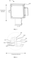
FIG. 1 is a schematic structural diagram of a camera assembly according to an embodiment of this application; -
FIG. 2 is a schematic structural diagram of a camera assembly according to an embodiment of this application; -
FIG. 3 is a schematic structural diagram of a camera assembly according to an embodiment of this application; -
FIG. 4 is a schematic diagram of a partially enlarged structure of a camera assembly according to an embodiment of this application; -
FIG. 5 is a schematic diagram of a partially enlarged structure of a camera assembly according to an embodiment of this application; -
FIG. 6 is a schematic structural diagram of a camera assembly according to an embodiment of this application; -
FIG. 7 is a schematic structural diagram of a camera assembly according to an embodiment of this application; and -
FIG. 8 is a schematic structural diagram of an electronic device according to an embodiment of this application. - A correspondence between reference numerals and component names in
FIG. 1 to FIG. 8 is as follows:
100 camera assembly; 102 first holder; 1022 first protrusion; 1023 first mating chamfer; 1024 first installation position: 1025 first avoidance groove; 104 second holder; 1042 second protrusion; 1043 second mating chamfer; 1044 second installation position; 1045 second avoidance groove; 106 sealing member; 108 heat dissipation plate; 202 first camera; 204 second camera; 300 electronic device; and 302 body. - Embodiments of this application will be described below in detail, and examples of the embodiments are illustrated in the accompanying drawings. The same or similar reference numerals always indicate the same or similar elements or elements having the same or similar functions. The embodiments described below with reference to the accompanying drawings are exemplary, and are only intended to explain this application and should not be understood as a limitation of this application. All other embodiments obtained by a person of ordinary skill in the art based on the embodiments of this application shall fall within the protection scope of this application.
- Features of the terms "first" and "second" in the specification and claims of this application may explicitly or implicitly include one or more of the features. In the description of this application, unless otherwise specified, "a plurality of" means two or more. In addition, in the specification and the claims, "and/or" represents at least one of connected objects, and a character "/" generally represents an "or" relationship between associated objects.
- In the description of this application, it should be noted that, unless specifically defined and limited otherwise, meanings of terms "install", "connected with", and "connected to" should be understood in a board sense. For example, the connection may be a fixed connection, a removable connection, or an integral connection; may be a mechanical connection or an electrical connection; may be a direct connection or an indirect connection by using an intermediate medium; or may be intercommunication between two components. For a person of ordinary skill in the art, the specific meanings of the foregoing terms in this application may be understood according to specific circumstances.
- The camera assembly provided in the embodiments of this application is mainly used for the electronic device, for example, a mobile terminal such as a mobile phone, a wearable device, a tablet computer, a laptop computer, a mobile computer, a handheld game console, a video recorder, a camcorder, or the like. Certainly, the camera assembly can also be applied not only to the electronic device but also to other devices that are used to take pictures through cameras.
- A
camera assembly 100 and anelectronic device 300 provided in the embodiments of this application will be described below with reference toFIG. 1 to FIG. 8 . - As shown in
FIG. 1 to FIG. 6 , an embodiment of this application proposes acamera assembly 100, which includes afirst holder 102 and asecond holder 104, and afirst camera 202 and asecond camera 204 respectively disposed on thefirst holder 102 and thesecond holder 104. Thefirst holder 102 and thesecond holder 104 are disposed adjacent to each other, and thefirst holder 102 and thesecond holder 104 are separately provided with protrusions extending towards the other side. Further, thefirst holder 102 is provided with afirst protrusion 1022 extending towards thesecond holder 104, and thesecond holder 104 is provided with asecond protrusion 1042 extending towards thefirst holder 102. Based on a staggered and stacked arrangement of thefirst protrusion 1022 and thesecond protrusion 1042, an overall size of thecamera assembly 100 in a direction adjacent to thefirst holder 102 and thesecond holder 104 is greatly reduced by using a common edge space, which is conducive to a miniaturization design. In this way, in a limited space, an installation space can be provided for other products. For example, when being applied to a smart phone, thecamera assembly 100 can provide a space for a battery, a wireless charging coil, and the like, so as to realize higher power charging and greatly enhance the competitiveness of the product. - In addition, by integrating the
camera assembly 100 as a whole, the modular design can be improved, which also facilitates the production and assembly of the product. - In this embodiment of this application, the
first holder 102 and thesecond holder 104 are disposed adjacent to each other, and the size of thefirst protrusion 1022 and thesecond protrusion 1042 in the connection direction can be effectively reduced under an overlapping action. - It should be noted that, as shown in
FIG. 1 to FIG. 3 , the connection direction of thefirst holder 102 and thesecond holder 104 is an adjacent direction of thefirst holder 102 and thesecond holder 104. For example, if thefirst holder 102 is disposed on the front side of thesecond holder 104, the connection direction is a front-back direction, and if thefirst holder 102 is disposed on the left side of thesecond holder 104, the connection direction is the left-right direction. When a plurality ofcamera assemblies 100 proposed in this embodiment are used in one product, sizes ofdifferent camera assemblies 100 in the connection direction can be further controlled, which can be flexibly selected based on a specific position and space limitation. - Further, a structure of the
first holder 102 is shown inFIG. 2 , a lower side in a connection direction is provided with thefirst protrusion 1022, and a structure of thesecond holder 104 is shown inFIG. 3 , an upper side in a connection direction is provided with thesecond protrusion 1042. - Certainly, there may be one or more
first cameras 202 on thefirst holder 102, and there may be one or moresecond cameras 204 on thesecond holder 104. - In a specific embodiment, as shown in
FIG. 1 , there are onefirst holder 102 and onesecond holder 104, thefirst holder 102 is provided with onefirst camera 202, and thesecond holder 104 is provided with onesecond camera 204. - In another specific embodiment, the number of the
first holders 102 is two, and the twofirst holders 102 are integrally formed. Since eachfirst holder 102 is provided with afirst camera 202, after the twofirst holders 102 are integrally processed, a part matching differentsecond holders 104 in a staggered and stacked manner may be formed, and the size can be further reduced in a plurality of directions or in a single direction. Certainly, it can further be understood that because installation positions of different cameras need to meet specific requirements, installation position requirements of specific cameras can further be met through the foregoing integrated forming method. - Further, the
first holder 102 and thesecond holder 104 are disposed adjacent to each other. As shown inFIG. 4 , afirst mating chamfer 1023 and asecond mating chamfer 1043 are respectively disposed on thefirst protrusion 1022 and thesecond protrusion 1042, so that thefirst protrusion 1022 and thesecond protrusion 1042 can be attached more closely through the abutment between the chamfers. This further reduces the overall size of thefirst holder 102 and thesecond holder 104 in the connection direction after being connected. - Specifically, a side of the
first protrusion 1022 close to thesecond protrusion 1042 is provided with afirst mating chamfer 1023, a side of thesecond protrusion 1042 close to thefirst protrusion 1022 is provided with asecond mating chamfer 1043, and thefirst mating chamfer 1023 abuts against thesecond mating chamfer 1043. - In a specific embodiment, the
first holder 102 and thesecond holder 104 are disposed left and right, thefirst protrusion 1022 is disposed on the right side of thefirst holder 102, thesecond protrusion 1042 is disposed on the left side of thesecond holder 104, thefirst mating chamfer 1023 is disposed on the right side of thefirst protrusion 1022, and thesecond mating chamfer 1043 is disposed on the left side of thesecond protrusion 1042. - Further, as shown in
FIG. 4 , thefirst holder 102 and thesecond holder 104 are disposed adjacent to each other, thefirst holder 102 is provided with afirst avoidance groove 1025 adjacent to thefirst protrusion 1022, thesecond holder 104 is provided with asecond avoidance groove 1045 adjacent to thesecond protrusion 1042, thefirst protrusion 1022 is disposed in thesecond avoidance groove 1045, and thesecond protrusion 1042 is disposed in thefirst avoidance groove 1025. - It can be understood that after protruding outward from the
first holder 102 to form thefirst protrusion 1022, an adjacent depression, that is, thefirst avoidance groove 1025, will inevitably be formed adjacent to thefirst protrusion 1022. When thefirst holder 102 and thesecond holder 104 are mated, thefirst protrusion 1022 may be disposed in thesecond avoidance groove 1045, and thesecond protrusion 1042 may be disposed in thefirst avoidance groove 1025. An overlapping degree between thefirst protrusion 1022 and thesecond protrusion 1042 is higher, which is more beneficial to reduce the size of thefirst holder 102 and thesecond holder 104 in the connection direction when thefirst protrusion 1022 and thesecond protrusion 1042 are mated. - Further, there are a plurality of
first protrusions 1022, and thefirst avoidance groove 1025 is disposed between any two adjacentfirst protrusions 1022. There are a plurality ofsecond protrusions 1042, thesecond avoidance groove 1045 is disposed between any two adjacentsecond protrusions 1042, and thefirst protrusions 1022 and thesecond protrusions 1042 are disposed in a staggered manner. Through the foregoing arrangement manner, a wave coordination or a sawtooth coordination can be formed between thefirst protrusion 1022 and thesecond protrusion 1042. On this basis, when thefirst holder 102 and thesecond holder 104 are disposed adjacent to each other, the connection stability of thefirst holder 102 and thesecond holder 104 can be enhanced under the joint action of the protrusions and the avoidance grooves. - Further, as shown in
FIG. 5 , thefirst holder 102 and thesecond holder 104 are adjacent to each other. By disposing the sealingmember 106 between thefirst protrusion 1022 and thesecond protrusion 1042, tiny substances such as dust and liquid can be effectively prevented from passing through the gap between thefirst protrusion 1022 and thesecond protrusion 1042 and moving to back sides of thefirst holder 102 and thesecond holder 104, thus reducing corrosion for electronic components such as a circuit board on the back side, and the like. - Specifically, the sealing
member 106 is disposed on a side of thefirst protrusion 1022, and further, disposed on the side of thefirst protrusion 1022 away from thefirst holder 102, so that when thefirst protrusion 1022 abuts against thesecond protrusion 1042, the sealingmember 106 can be attached to thesecond protrusion 1042 to ensure a sealing effect between thefirst protrusion 1022 and thesecond protrusion 1042. - Further, as for disposing a camera on the
first holder 102 and thesecond holder 104, a sealing requirement of the camera for taking pictures can be better met by disposing the sealingmember 106. - In a specific embodiment, the sealing
member 106 is disposed on thefirst protrusion 1022. - In another embodiment, the sealing
member 106 is disposed on thesecond protrusion 1042. - In another embodiment, both the
first protrusion 1022 and thesecond protrusion 1042 are separately provided with the sealingmember 106, and the two sealingmembers 106 are attached to each other. - In another embodiment, as shown in
FIG. 4 , aheat dissipation plate 108 can be disposed between thefirst protrusion 1022 and thesecond protrusion 1042, so that an entire bottom of thecamera assembly 100 can be conducted to the outside. Specifically, one end of theheat dissipation plate 108 abuts against a bottom of thefirst holder 102 or a bottom of thesecond holder 104, and the other end is disposed between thefirst protrusion 1022 and thesecond protrusion 1042, thereby expanding a heat dissipation area and enhancing a heat dissipation effect. - In another embodiment, a part of the
heat dissipation plate 108 between thefirst protrusion 1022 and thesecond protrusion 1042 can play a sealing role, that is, the part achieves both the effect of a heat dissipation member and the effect of the sealingmember 106. - Furthermore, one or more
first installation positions 1024 can be disposed on thefirst holder 102, so that different numbers offirst cameras 202 can be installed on thefirst holder 102, so as to meet different photographing requirements. On this basis, thefirst protrusion 1022 is disposed on a periphery of thefirst installation position 1024, so that the overall size of thefirst holder 102 and thesecond holder 104 in the connection direction when being connected can be reduced without affecting a normal shooting function of thefirst camera 202 on thefirst holder 102. - Further, the number of the
first installation positions 1024 on thefirst holder 102 can be set based on the size of thefirst camera 202 and the size of thefirst holder 102, and it is certain that imaging effects ofdifferent cameras 202 may also be considered. - Similarly, as for the
second holder 104, one or moresecond installation positions 1044 for installing thesecond camera 204 can be disposed on thesecond holder 104, and during using, thesecond camera 204 can be installed on eachsecond installation position 1044 to achieve shooting through thesecond camera 204. On this basis, thesecond protrusion 1042 is disposed on a periphery of thesecond installation position 1044. Generally, thesecond camera 204 finds a view through an axial direction. Therefore, by disposing thesecond protrusion 1042 in the periphery, on the one hand, interference to thesecond camera 204 for finding a view is reduced during connection, and on the other hand, the size in the connection direction can be reduced through an overlapping relationship between thefirst protrusion 1022 and thesecond protrusion 1042. - The connection between the
first camera 202 and thefirst installation position 1024 may be detachable or fixed, and the connection between thesecond camera 204 and thesecond installation position 1044 may also be detachable or fixed. - Further, when the cameras is separately installed on the
first installation position 1024 and thesecond installation position 1044, the light entering direction of the camera on thefirst installation position 1024 is parallel to the light entering direction of the camera on thesecond installation position 1044 during installation, that is, the light entering direction of thefirst camera 202 on thefirst installation position 1024 and the light entering direction of thesecond camera 204 on thesecond installation position 1044 are parallel to each other, so as to simultaneously optimize an image through a plurality of cameras during imaging, and it is also convenient to switch among a plurality of cameras with a same view finding direction during imaging. - On the basis that the light entering direction of the
first camera 202 is parallel to the light entering direction of thesecond camera 204, the number of thefirst holders 102 is two, and the twofirst holders 102 are integrally formed. Since eachfirst holder 102 is provided with afirst camera 202, after the twofirst holders 102 are integrally processed, a part matching differentsecond holders 104 in a staggered and stacked manner may be formed, and the size can be further reduced in a plurality of directions or in a single direction. Certainly, it can further be understood that because installation positions of different cameras need to meet specific requirements, installation position requirements of specific cameras can further be met through the foregoing integrated forming method. - In addition, as shown in
FIG. 7 , this application further provides a specific embodiment of thecamera assembly 100, including afirst holder 102 with afirst camera 202 and asecond holder 104 with asecond camera 204. Layout of four cameras is shown in the figure, a master camera is placed in the center, and the other three cameras are placed around the master camera. Because these three cameras need to cooperate with the master camera during operating, the three cameras all need to be close to the master camera in finding a view and cannot be too far away from the master camera, otherwise, the imaging effect will be poor. Micro pan/tilt herein is used as a wide-angle camera. - After the number of cameras of the mobile phone has increased to 4, and the micro pan/tilt and a periscope camera are relatively large as an individual, on the whole, it seems that an area occupied by 4 modules is relatively large. At first glance, there is a sense of abruptness, which is not delicate. In addition, the 4 camera modules are relatively large, and a space occupied by corresponding camera lenses will be relatively large. Because the camera lens is made of glass, the larger the lens, the easier it will crack during falling. In addition, because the 4 camera modules are relatively large, a space occupied on a printed circuit board (Printed Circuit Board, PCB) will be relatively large, and an available layout area for the PCB is small. As a result, a width or length of the entire camera need to be increased to meet a layout space of the PCB. In order to alleviate the foregoing problem, every two camera holders that are close to each other share one camera holder wall thickness in a Z-direction overlapped and distributed manner. As shown in
FIG. 7 , the micro pan/tilt camera and the master camera holder share one wall thickness A, and the master camera and the periscope camera share one wall thickness B. By adopting this structure, the overall size can be reduced by two holder wall thicknesses in Y direction (namely, an up and down direction inFIG. 7 ), and can be reduced by one holder wall thickness C in X direction. Due to the reduction of module size, the area of camera lens can be reduced, which can reduce the failure rate of camera lens, and can further improve a layout utilization rate of the PCB and optimize an outline size of mobile phone. In addition, when a distance between camera bodies is small, the imaging effect is better. - Further, as shown in
FIG. 1 , each of a holder of the micro-pan/tilt camera and a holder of the master camera keeps only half of the height of Z direction at adjacent positions, and the two holders overlap in the Z direction. A micro pan/tilt holder is disposed in the upper part, and a master camera holder is in the lower part. - Based on this, the Z-direction distribution design for disposing the camera holder needs to facilitate the assembly of the camera. In this embodiment, the master camera (that is, the
first camera 202 in the center) is installed first, and then the micro pan/tilt (thesecond camera 204 located above) and the periscope camera (thesecond camera 204 at the lower right) are installed. A portrait camera is directly positioned on the master camera holder (that is, the holder of thefirst camera 202 located below is integrally formed with the holder of the first camera in the center). - Due to the structure particularity of the micro-pan/tilt, dust can directly fall on the surface of the lens after entering from the bottom. In order to ensure the dust-proof effect, a copper foil is required to be attached to the side to connect to the base to prevent dust from entering. In order to facilitate copper foil fitting, a transition of C-angle bevel (that is, the
first mating chamfer 1023 and the second mating chamfer 1043) is required for the holder. This copper foil may improve both the heat dissipation performance and the electronic shielding performance of the camera. - As shown in
FIG. 8 , anelectronic device 300 provided in an embodiment of this application includes abody 302 and acamera assembly 100. Thecamera assembly 100 is disposed on thebody 302, and thecamera assembly 100 can be a front camera module of theelectronic device 300 or a rear camera module of theelectronic device 300. The user may use thecamera assembly 100 to take selfies and find views, so as to meet different shooting requirements. - In another embodiment, the
first camera 202 of thecamera assembly 100 may face the front of theelectronic device 300, and thesecond camera 204 may face the back of theelectronic device 300, so that thecamera assembly 100 can be used to find views and take pictures in both the front and back directions, which can better meet different use requirements of users. - The electronic device in the embodiments of this application may be specifically a mobile terminal such as a mobile phone, a wearable device, a tablet computer, a laptop computer, a mobile computer, a handheld game console, a video recorder, a camcorder, or the like. Certainly, the camera assembly can also be applied not only to the electronic device but also to other devices that are used to take pictures.
- According to the embodiments of the camera assembly and the electronic device of this application, the first protrusion and the second protrusion are disposed in a staggered manner, which can reduce the space occupied by the first protrusion and the second protrusion at the joint, that is, the space occupied by the entire camera assembly is also reduced. Especially in a limited space, this can provide an installation space for other products.
- In the description of this specification, description of the terms "an embodiment", "some embodiments", "specific embodiments" and the like means that a particular feature, structure, material, or characteristic described in combination with the embodiment or example is included in at least one embodiment or example of this application. In this specification, schematic representations of the foregoing terms are not necessarily directed to the same embodiment or example. Moreover, the particular feature, structure, material or characteristic described may be combined in any suitable manner in any one or more embodiments or examples.
- The description above is only preferable embodiments of this application, and is not used to limit this application. For a person skilled in the art, this application may have various modifications and changes. Any modification, equivalent replacement and improvement made within the spirit and principle of this application shall be included in the protection scope of this application.
Claims (10)
- A camera assembly, comprising: a first holder, a second holder, a first camera, and a second camera, whereinthe first camera is disposed on the first holder, and the second camera is disposed on the second holder; andthe second holder is disposed adjacent to the first holder, the first holder is provided with a first protrusion extending towards the second holder, the second holder is provided with a second protrusion extending towards the first holder, and the first protrusion and the second protrusion are disposed in a staggered and stacked manner.
- The camera assembly according to claim 1, wherein a side of the first protrusion close to the second protrusion is provided with a first mating chamfer, a side of the second protrusion close to the first protrusion is provided with a second mating chamfer, and the first mating chamfer abuts against the second mating chamfer.
- The camera assembly according to claim 1, wherein the first holder is provided with a first avoidance groove adjacent to the first protrusion, the second holder is provided with a second avoidance groove adjacent to the second protrusion, the first protrusion is disposed in the second avoidance groove, and the second protrusion is disposed in the first avoidance groove.
- The camera assembly according to claim 3, wherein there are a plurality of first protrusions, and the first avoidance groove is disposed between any two adjacent first protrusions; and
there are a plurality of second protrusions, the second avoidance groove is disposed between any two adjacent second protrusions, and the first protrusions and the second protrusions are disposed in a staggered manner. - The camera assembly according to any one of claims 1 to 4, further comprising:a sealing member, wherein the sealing member is disposed on a side of the first protrusion away from the first holder, and the sealing member is attached to the second holder; and/orthe sealing member is disposed on a side of the second protrusion away from the second holder, and the sealing member is attached to the first holder.
- The camera assembly according to any one of claims 1 to 4, wherein the first protrusion and the second protrusion are in surface contact, and the camera assembly further comprises:
a heat dissipation plate, wherein one end of the heat dissipation plate abuts against a bottom of the first holder or a bottom of the second holder, and other end of the heat dissipation plate is disposed between the first protrusion and the second protrusion. - The camera assembly according to any one of claims 1 to 4, further comprising:at least one first installation position disposed on the first holder, wherein each first installation position is used to install the first camera, and the first protrusion is disposed on a periphery of the first installation position; andat least one second installation position disposed on the second holder, wherein each second installation position is used to install the second camera, and the second protrusion is disposed on a periphery of the second installation position.
- The camera assembly according to any one of claims 1 to 4, wherein a light entering direction of the first camera is parallel to a light entering direction of the second camera.
- The camera assembly according to claim 8, wherein a number of the first holder is two, and the two first holders are integrally formed.
- An electronic device, comprising:a body; andat least one camera assembly according to any one of claims 1 to 9, disposed on the body, wherein the camera assembly comprises at least one of following camera modules: a front camera module of the electronic device and a rear camera module of the electronic device.
Applications Claiming Priority (2)
| Application Number | Priority Date | Filing Date | Title |
|---|---|---|---|
| CN202011496046.9A CN112565579B (en) | 2020-12-17 | 2020-12-17 | Camera assembly and electronic equipment |
| PCT/CN2021/137137 WO2022127706A1 (en) | 2020-12-17 | 2021-12-10 | Camera assembly and electronic device |
Publications (3)
| Publication Number | Publication Date |
|---|---|
| EP4266663A1 true EP4266663A1 (en) | 2023-10-25 |
| EP4266663A4 EP4266663A4 (en) | 2024-06-12 |
| EP4266663B1 EP4266663B1 (en) | 2025-12-24 |
Family
ID=75063026
Family Applications (1)
| Application Number | Title | Priority Date | Filing Date |
|---|---|---|---|
| EP21905635.5A Active EP4266663B1 (en) | 2020-12-17 | 2021-12-10 | Camera assembly and electronic device |
Country Status (6)
| Country | Link |
|---|---|
| US (1) | US12604106B2 (en) |
| EP (1) | EP4266663B1 (en) |
| JP (1) | JP7540097B2 (en) |
| CN (1) | CN112565579B (en) |
| ES (1) | ES3060438T3 (en) |
| WO (1) | WO2022127706A1 (en) |
Families Citing this family (4)
| Publication number | Priority date | Publication date | Assignee | Title |
|---|---|---|---|---|
| CN112565579B (en) * | 2020-12-17 | 2022-10-28 | 维沃移动通信有限公司 | Camera assembly and electronic equipment |
| EP4362486B1 (en) * | 2021-08-18 | 2026-03-11 | Samsung Electronics Co., Ltd. | Camera bracket and electronic device comprising same |
| CN118540558B (en) * | 2023-02-22 | 2025-04-18 | 荣耀终端股份有限公司 | Camera components and electronic devices |
| WO2024202957A1 (en) * | 2023-03-28 | 2024-10-03 | ソニーセミコンダクタソリューションズ株式会社 | Compound eye camera module and electronic apparatus |
Family Cites Families (24)
| Publication number | Priority date | Publication date | Assignee | Title |
|---|---|---|---|---|
| CN203688967U (en) | 2014-01-06 | 2014-07-02 | 北京大国慧谷科技有限公司 | Imaging device installation component with convenient assembly and panoramic imaging device bracket |
| GB2546075A (en) * | 2016-01-05 | 2017-07-12 | Oclu Ltd | A camera mount |
| WO2018028718A1 (en) * | 2016-08-12 | 2018-02-15 | 宁波舜宇光电信息有限公司 | Camera module based on integral encapsulation technique and array camera module |
| CN108206907B (en) * | 2016-12-20 | 2024-06-14 | 宁波舜宇光电信息有限公司 | Array camera module and electronic equipment |
| CN108243297A (en) * | 2016-12-23 | 2018-07-03 | 宁波舜宇光电信息有限公司 | Camera module and its circuit board assemblies and manufacturing method and the electronic equipment with camera module |
| TWM547115U (en) * | 2017-05-15 | 2017-08-11 | Lips Corp | Expandable dual-lens device |
| CN107181900A (en) * | 2017-06-05 | 2017-09-19 | 信利光电股份有限公司 | It is a kind of double to take the photograph module bracket, double take the photograph module and mobile terminal |
| CN206908708U (en) * | 2017-07-12 | 2018-01-19 | 广东欧珀移动通信有限公司 | The CCD camera assembly and electronic equipment of electronic equipment |
| CN207999598U (en) * | 2017-12-28 | 2018-10-23 | 信利光电股份有限公司 | A kind of panoramic shooting module bracket and electronic equipment |
| JP2019184854A (en) * | 2018-04-11 | 2019-10-24 | ソニーセミコンダクタソリューションズ株式会社 | Imaging apparatus, electronic apparatus, and method for manufacturing imaging apparatus |
| JP7151541B2 (en) * | 2018-07-24 | 2022-10-12 | 株式会社リコー | Imaging device |
| KR102705493B1 (en) * | 2018-10-11 | 2024-09-11 | 엘지이노텍 주식회사 | Camera Actuator and Camera module including the same |
| KR102774759B1 (en) * | 2019-01-22 | 2025-03-04 | 엘지이노텍 주식회사 | Camera Module |
| KR102849668B1 (en) | 2019-03-28 | 2025-08-22 | 엘지이노텍 주식회사 | Camera module |
| US11640039B2 (en) * | 2019-03-29 | 2023-05-02 | Apple Inc. | Welded bracket structure for a multi-camera system |
| CN210137372U (en) | 2019-07-23 | 2020-03-10 | RealMe重庆移动通信有限公司 | Camera support, camera assembly and electronic equipment |
| CN110519490A (en) * | 2019-07-23 | 2019-11-29 | RealMe重庆移动通信有限公司 | Camera module and electronic equipment |
| KR102754005B1 (en) * | 2020-02-21 | 2025-01-14 | 엘지전자 주식회사 | Mobile terminal |
| US11528399B2 (en) * | 2020-03-06 | 2022-12-13 | Apple Inc. | Housing structure for handheld electronic device |
| WO2021225362A1 (en) * | 2020-05-07 | 2021-11-11 | 엘지이노텍 주식회사 | Camera device |
| CN111818248B (en) * | 2020-07-17 | 2022-02-15 | Oppo广东移动通信有限公司 | Bracket structure, camera assembly and electronic equipment |
| KR102865252B1 (en) * | 2020-07-21 | 2025-09-30 | 삼성전자 주식회사 | Camera structure and electronic device including the same |
| CN112565579B (en) * | 2020-12-17 | 2022-10-28 | 维沃移动通信有限公司 | Camera assembly and electronic equipment |
| US20240406527A1 (en) * | 2023-06-02 | 2024-12-05 | Apple Inc. | Camera Arrangements with Mounted Image Sensors |
-
2020
- 2020-12-17 CN CN202011496046.9A patent/CN112565579B/en active Active
-
2021
- 2021-12-10 JP JP2023536949A patent/JP7540097B2/en active Active
- 2021-12-10 WO PCT/CN2021/137137 patent/WO2022127706A1/en not_active Ceased
- 2021-12-10 ES ES21905635T patent/ES3060438T3/en active Active
- 2021-12-10 EP EP21905635.5A patent/EP4266663B1/en active Active
-
2023
- 2023-06-16 US US18/210,806 patent/US12604106B2/en active Active
Also Published As
| Publication number | Publication date |
|---|---|
| EP4266663A4 (en) | 2024-06-12 |
| JP2023554427A (en) | 2023-12-27 |
| US12604106B2 (en) | 2026-04-14 |
| CN112565579A (en) | 2021-03-26 |
| ES3060438T3 (en) | 2026-03-26 |
| CN112565579B (en) | 2022-10-28 |
| EP4266663B1 (en) | 2025-12-24 |
| US20230328398A1 (en) | 2023-10-12 |
| WO2022127706A1 (en) | 2022-06-23 |
| JP7540097B2 (en) | 2024-08-26 |
Similar Documents
| Publication | Publication Date | Title |
|---|---|---|
| US12604106B2 (en) | Camera assembly and electronic device | |
| CN110049222B (en) | Mobile terminal | |
| US20070153120A1 (en) | Imaging apparatus | |
| EP4145813A1 (en) | Electronic device | |
| US20070147830A1 (en) | Imaging apparatus | |
| CN218830008U (en) | Electronic equipment | |
| EP4195642A1 (en) | Electronic device | |
| CN112702498B (en) | Camera module and electronic equipment | |
| CN210137339U (en) | Electronic equipment | |
| CN217936414U (en) | Electronic device | |
| CN107147835B (en) | electronic device | |
| CN221900943U (en) | Electronic equipment bracket and electronic equipment | |
| US20250392661A1 (en) | Electronic device | |
| CN209120290U (en) | A kind of camera module and terminal | |
| EP4192214A1 (en) | Circuit board assembly and electronic device | |
| CN209659434U (en) | Terminal device | |
| CN110198370B (en) | An electronic device and a photographing control method of the electronic device | |
| CN223141962U (en) | Electronic equipment | |
| CN224052477U (en) | Imaging lens, camera module and electronic device | |
| CN222674451U (en) | Earphone box | |
| CN113114876A (en) | Electronic equipment | |
| US20260029694A1 (en) | Image capturing apparatus equipped with stand | |
| US20250120011A1 (en) | Electronic element assembly, image sensor module, camera module and electronic device | |
| US20260020143A1 (en) | Circuit board, circuit board assembly, and electronic device | |
| EP4648431A1 (en) | Camera assembly and electronic device |
Legal Events
| Date | Code | Title | Description |
|---|---|---|---|
| STAA | Information on the status of an ep patent application or granted ep patent |
Free format text: STATUS: THE INTERNATIONAL PUBLICATION HAS BEEN MADE |
|
| PUAI | Public reference made under article 153(3) epc to a published international application that has entered the european phase |
Free format text: ORIGINAL CODE: 0009012 |
|
| STAA | Information on the status of an ep patent application or granted ep patent |
Free format text: STATUS: REQUEST FOR EXAMINATION WAS MADE |
|
| 17P | Request for examination filed |
Effective date: 20230713 |
|
| AK | Designated contracting states |
Kind code of ref document: A1 Designated state(s): AL AT BE BG CH CY CZ DE DK EE ES FI FR GB GR HR HU IE IS IT LI LT LU LV MC MK MT NL NO PL PT RO RS SE SI SK SM TR |
|
| DAV | Request for validation of the european patent (deleted) | ||
| DAX | Request for extension of the european patent (deleted) | ||
| REG | Reference to a national code |
Ref country code: DE Ref country code: DE Ref legal event code: R079 Ref document number: 602021045229 Country of ref document: DE Free format text: PREVIOUS MAIN CLASS: H04N0005225000 Ipc: H04N0023570000 |
|
| A4 | Supplementary search report drawn up and despatched |
Effective date: 20240515 |
|
| RIC1 | Information provided on ipc code assigned before grant |
Ipc: H04N 23/90 20230101ALI20240508BHEP Ipc: H04N 23/57 20230101AFI20240508BHEP |
|
| GRAP | Despatch of communication of intention to grant a patent |
Free format text: ORIGINAL CODE: EPIDOSNIGR1 |
|
| STAA | Information on the status of an ep patent application or granted ep patent |
Free format text: STATUS: GRANT OF PATENT IS INTENDED |
|
| GRAS | Grant fee paid |
Free format text: ORIGINAL CODE: EPIDOSNIGR3 |
|
| INTG | Intention to grant announced |
Effective date: 20251016 |
|
| GRAA | (expected) grant |
Free format text: ORIGINAL CODE: 0009210 |
|
| STAA | Information on the status of an ep patent application or granted ep patent |
Free format text: STATUS: THE PATENT HAS BEEN GRANTED |
|
| AK | Designated contracting states |
Kind code of ref document: B1 Designated state(s): AL AT BE BG CH CY CZ DE DK EE ES FI FR GB GR HR HU IE IS IT LI LT LU LV MC MK MT NL NO PL PT RO RS SE SI SK SM TR |
|
| REG | Reference to a national code |
Ref country code: CH Ref legal event code: F10 Free format text: ST27 STATUS EVENT CODE: U-0-0-F10-F00 (AS PROVIDED BY THE NATIONAL OFFICE) Effective date: 20251224 Ref country code: GB Ref legal event code: FG4D |
|
| REG | Reference to a national code |
Ref country code: DE Ref legal event code: R096 Ref document number: 602021045229 Country of ref document: DE |
|
| REG | Reference to a national code |
Ref country code: NL Ref legal event code: FP |
|
| REG | Reference to a national code |
Ref country code: ES Ref legal event code: FG2A Ref document number: 3060438 Country of ref document: ES Kind code of ref document: T3 Effective date: 20260326 |
|
| REG | Reference to a national code |
Ref country code: LT Ref legal event code: MG9D |
|
| PG25 | Lapsed in a contracting state [announced via postgrant information from national office to epo] |
Ref country code: NO Free format text: LAPSE BECAUSE OF FAILURE TO SUBMIT A TRANSLATION OF THE DESCRIPTION OR TO PAY THE FEE WITHIN THE PRESCRIBED TIME-LIMIT Effective date: 20260324 |
|
| PG25 | Lapsed in a contracting state [announced via postgrant information from national office to epo] |
Ref country code: HR Free format text: LAPSE BECAUSE OF FAILURE TO SUBMIT A TRANSLATION OF THE DESCRIPTION OR TO PAY THE FEE WITHIN THE PRESCRIBED TIME-LIMIT Effective date: 20251224 Ref country code: FI Free format text: LAPSE BECAUSE OF FAILURE TO SUBMIT A TRANSLATION OF THE DESCRIPTION OR TO PAY THE FEE WITHIN THE PRESCRIBED TIME-LIMIT Effective date: 20251224 |
|
| PG25 | Lapsed in a contracting state [announced via postgrant information from national office to epo] |
Ref country code: RS Free format text: LAPSE BECAUSE OF FAILURE TO SUBMIT A TRANSLATION OF THE DESCRIPTION OR TO PAY THE FEE WITHIN THE PRESCRIBED TIME-LIMIT Effective date: 20260324 |
|
| PG25 | Lapsed in a contracting state [announced via postgrant information from national office to epo] |
Ref country code: LV Free format text: LAPSE BECAUSE OF FAILURE TO SUBMIT A TRANSLATION OF THE DESCRIPTION OR TO PAY THE FEE WITHIN THE PRESCRIBED TIME-LIMIT Effective date: 20251224 |
|
| PG25 | Lapsed in a contracting state [announced via postgrant information from national office to epo] |
Ref country code: BG Free format text: LAPSE BECAUSE OF FAILURE TO SUBMIT A TRANSLATION OF THE DESCRIPTION OR TO PAY THE FEE WITHIN THE PRESCRIBED TIME-LIMIT Effective date: 20251224 |