EP4266501A1 - Dual polarized antenna with dual feed and cross polarization isolation - Google Patents
Dual polarized antenna with dual feed and cross polarization isolation Download PDFInfo
- Publication number
- EP4266501A1 EP4266501A1 EP23167074.6A EP23167074A EP4266501A1 EP 4266501 A1 EP4266501 A1 EP 4266501A1 EP 23167074 A EP23167074 A EP 23167074A EP 4266501 A1 EP4266501 A1 EP 4266501A1
- Authority
- EP
- European Patent Office
- Prior art keywords
- waveguide
- feed
- rectangular
- face
- antenna
- Prior art date
- Legal status (The legal status is an assumption and is not a legal conclusion. Google has not performed a legal analysis and makes no representation as to the accuracy of the status listed.)
- Granted
Links
Images



Classifications
-
- H—ELECTRICITY
- H01—ELECTRIC ELEMENTS
- H01Q—ANTENNAS, i.e. RADIO AERIALS
- H01Q21/00—Antenna arrays or systems
- H01Q21/24—Combinations of antenna units polarised in different directions for transmitting or receiving circularly and elliptically polarised waves or waves linearly polarised in any direction
-
- H—ELECTRICITY
- H01—ELECTRIC ELEMENTS
- H01Q—ANTENNAS, i.e. RADIO AERIALS
- H01Q21/00—Antenna arrays or systems
- H01Q21/0006—Particular feeding systems
- H01Q21/0037—Particular feeding systems linear waveguide fed arrays
- H01Q21/0043—Slotted waveguides
-
- H—ELECTRICITY
- H01—ELECTRIC ELEMENTS
- H01Q—ANTENNAS, i.e. RADIO AERIALS
- H01Q13/00—Waveguide horns or mouths; Slot antennas; Leaky-waveguide antennas; Equivalent structures causing radiation along the transmission path of a guided wave
- H01Q13/10—Resonant slot antennas
-
- H—ELECTRICITY
- H01—ELECTRIC ELEMENTS
- H01Q—ANTENNAS, i.e. RADIO AERIALS
- H01Q25/00—Antennas or antenna systems providing at least two radiating patterns
- H01Q25/001—Crossed polarisation dual antennas
-
- H—ELECTRICITY
- H01—ELECTRIC ELEMENTS
- H01P—WAVEGUIDES; RESONATORS, LINES, OR OTHER DEVICES OF THE WAVEGUIDE TYPE
- H01P5/00—Coupling devices of the waveguide type
- H01P5/02—Coupling devices of the waveguide type with invariable factor of coupling
- H01P5/022—Transitions between lines of the same kind and shape, but with different dimensions
- H01P5/024—Transitions between lines of the same kind and shape, but with different dimensions between hollow waveguides
-
- H—ELECTRICITY
- H01—ELECTRIC ELEMENTS
- H01Q—ANTENNAS, i.e. RADIO AERIALS
- H01Q1/00—Details of, or arrangements associated with, antennas
- H01Q1/27—Adaptation for use in or on movable bodies
- H01Q1/32—Adaptation for use in or on road or rail vehicles
- H01Q1/3208—Adaptation for use in or on road or rail vehicles characterised by the application wherein the antenna is used
- H01Q1/3233—Adaptation for use in or on road or rail vehicles characterised by the application wherein the antenna is used particular used as part of a sensor or in a security system, e.g. for automotive radar, navigation systems
Definitions
- Radar systems and communication systems send and receive radio signals via transmitting and receiving antennas.
- Some antennas are formed as a linear array of emitters to transmit and receive radio signals.
- the linear array allows for beamforming, in which the same signal is received with a different phase at each antenna element. The phase difference determines a direction for the beam.
- the linear array also allows for Multiple Input, Multiple Output (MIMO) techniques to create virtual antennas.
- the transmitted and received signals may have a specific polarization.
- a receiving antenna with a specific polarization may filter out signals that have a different polarization.
- a radio system may switch from one polarization to the other in order to isolate two different signals.
- an antenna has a waveguide having a first rectangular face at an end, a second rectangular face at a second opposite end, and a radiating face between the first rectangular face and the second rectangular face.
- a first feed is configured to feed a first radio signal having a first polarization into the waveguide.
- a second feed is configured to feed a second radio signal having a second polarization orthogonal to the first polarization into the waveguide.
- a first plurality of polarized emitters on the radiating face are arranged in a first line along the radiating face to emit the first radio signal, and a second plurality of polarized emitters on the radiating face are arranged in a second line along the radiating face to emit the second radio signal.
- the polarized emitters of the second plurality of polarized emitters are orthogonal to the polarized emitters of the first plurality of polarized emitters.
- the polarized emitters of the first plurality of polarized emitters are formed as linear slots through the radiating face.
- the radiating face comprises a conductive material and the linear slots are formed through the conductive material.
- the polarized emitters of the second plurality of polarized emitters are formed as linear slots through the radiating face orthogonal to the linear slots of the polarized emitters of the first plurality of polarized emitters.
- the waveguide has a waveguide axis that extends through the waveguide between the first rectangular face and the second rectangular face and wherein the linear slots of the first plurality of polarized emitters are parallel to the waveguide axis and the linear slots of second plurality of polarized emitters are perpendicular to the waveguide axis.
- the polarized emitters of the first plurality of polarized emitters are separated by a distance of one guided wavelength of the first radio signal.
- the linear slots of the first plurality of polarized emitters have a length of one half of a guided wavelength of the first radio signal.
- a first waveguide adapter is coupled between the first feed and the waveguide, wherein the first waveguide adapter is configured as a reflector of the second radio signal from the second feed into the waveguide, and a second waveguide adapter is coupled between the second feed and the waveguide, wherein the second waveguide adapter is configured as a reflector of the first radio signal from the first feed into the waveguide.
- the first waveguide adapter is trapezoidal having a first rectangular cross section with unequal adjacent sides and the second waveguide adapter is trapezoidal having a second rectangular cross section with unequal adjacent sides.
- a vertical side of a cross section of the first waveguide adapter is longer than a horizontal side of the cross section of the first waveguide adapter and a horizontal side of the cross section of the second waveguide adapter is longer than a vertical side of the cross section of the second waveguide adapter.
- the waveguide is in a shape of a rectangular parallelepiped with parallel walls.
- the first rectangular face and the second rectangular face are parallel and wherein a width of the first rectangular face is equal to the width of the second rectangular face.
- the first rectangular face and the second rectangular face are square.
- an apparatus in an embodiment, includes a first rectangular waveguide having a first rectangular face at an end, a second rectangular face at a second opposite end, and a radiating face between the first rectangular face and the second rectangular face, a second rectangular waveguide having a first rectangular face at an end, a second rectangular face at a second opposite end, and a radiating face between the first rectangular face and the second rectangular face, a first feed coupled to the first rectangular face of the first rectangular waveguide, the first feed configured to feed a first radio signal having a first polarization into the first rectangular waveguide, a second feed coupled to the first rectangular face of the second rectangular waveguide, the second feed configured to feed a second radio signal having the first polarization into the second rectangular waveguide, a first plurality of polarized emitters on the radiating face of the first rectangular waveguide arranged in a line along the radiating face to emit the first radio signal, and a second plurality of polarized emitters on the radiating face arranged in a line along the radiating face to emit the second radio signal
- the axis of the first rectangular waveguide is a longitudinal axis form the first rectangular face to the second rectangular face.
- the first radio signal and the second radio signal are a same radio signal, wherein the first feed and the second feed are both coupled to a same radio source wherein the first feed and the second feed are energized with the same radio signal.
- An embodiment includes a third feed coupled to the first rectangular waveguide, the third feed configured to feed a third radio signal having a second polarization into the first rectangular waveguide, a first feed adapter coupled to the first feed of the first rectangular waveguide and coupled to the first rectangular waveguide, the first feed adapter configured to conduct the first radio signal and to reflect the third radio signal, a fourth feed coupled to the second rectangular waveguide to feed a fourth radio signal having a second polarization into the second rectangular waveguide and, a second feed adapter coupled to the first feed of the second rectangular waveguide and coupled to the second rectangular waveguide, the second feed adapter configured to conduct the second radio signal and to reflect the fourth radio signal.
- the first rectangular waveguide comprises a solid dielectric material coated with a conductive material and wherein the first plurality of polarized emitters comprises linear slots formed through the conductive material.
- an antenna in an embodiment, includes a rectangular waveguide having a first rectangular face at an end, a second rectangular face at a second opposite end, and a radiating face between the first rectangular face and the second rectangular face, the waveguide being conductive and filled with a dielectric; a first feed configured to feed a first radio signal having a horizontal polarization into the waveguide, a first feed adapter coupled to the first feed on one side and the waveguide on the other side, the first feed adapter being tapered from the size of the waveguide to the first feed, a second feed configured to feed a second radio signal having a vertical polarization into the waveguide, wherein the vertical polarization is orthogonal to the horizontal polarization, a second feed adapter coupled to the second feed on one side and the waveguide on the other side, the second feed adapter being tapered from the size of the waveguide to the second feed, so that the second feed adapter is a reflector of the first radio signal, a first plurality of polarized emitters arranged in a first line along
- a single dual polarized antenna supports two simultaneous perpendicular polarizations, e.g. horizontal and vertical, to offer smaller dimensions, extremely low interference, reduced clutter reflections and more information about objects in a scene.
- each antenna is coupled to a waveguide that provides the radio signal to the antenna elements and receives radio signals from each antenna element.
- the linear array allows for beamforming, in which the same signal is received with a different phase at each antenna element. The phase difference determines a direction for the beam.
- the linear array also allows for Multiple Input, Multiple Output (MIMO) techniques to create virtual antennas
- a vertical polarized antenna and a separate horizontal polarized antenna may be combined in one compact waveguide using a separate feed for each antenna to provide excellent separation between the two signals.
- the antenna may be used for beamforming and MIMO communications.
- the antenna has two opposite feeding ports. This allows the feeds to switch between the two polarizations which can be used to reduce interference from other radars. The two feeds may be used to separate the horizontal polarized reflections from the vertical polarized reflections.
- Both modes may also be excited simultaneously due to the orthogonality of both waves propagating in both directions of the waveguide.
- the two feeding ports are independent of each other and the radiating slots for the two modes are independent of each other so that the characteristics for each polarization mode (such as the field of view (FOV), gain, sidelobes, etc.) can be designed independently.
- the antenna is able to be configured as two antennas in one structure. Even the center of phase of each polarization mode may be located separately, which is particularly useful for designing virtual elements of a MIMO radar.
- the described antenna has low losses due to the orthogonal feeding ports which function as a reflector for the orthogonal mode and provides very low leakage with high isolation.
- FIG. 1 is an isometric view of an example antenna 100 according to some embodiments.
- the antenna 100 has a waveguide 102 in the shape of a rectangular parallelepiped with a first rectangular face 104 for horizontal polarization at one end of the waveguide and a second rectangular face 106, parallel to the first rectangular face 104, for vertical polarization at an opposite end of the waveguide.
- the first rectangular face 104 and the second rectangular face 106 are parallel to each other and have the same dimension of length, y, and the same dimension of height, x.
- the length and height may be equal as for a square, as shown, or different as for a different rectangle to suit different implementations.
- the waveguide between the first and second rectangular faces has a rectangular cross section with four parallel walls or faces connecting the first and second rectangular faces.
- the waveguide is fed from one side with first radio signal by a horizontal waveguide adapter 110 at the first rectangular face 104 and from the other side with a second radio signal by a vertical waveguide adapter 112 at the second rectangular face 106.
- Waves propagate along a waveguide axis.
- the waveguide axis extends through the waveguide between the first rectangular face 104 and the second rectangular face 106.
- the waveguide is cut on a radiating face 108 at what is shown as the top surface to have two sets of radiating slots described in more detail below.
- some of the slots are linear slots and are elongated in a direction parallel to the waveguide axis and some of the slots are linear slots and are elongated in a direction perpendicular to the direction of propagation.
- the horizontal waveguide adapter 110 is coupled to the first rectangular face 104 on one side and is coupled to a first feed, in this example, a horizontal feed 116, on the other side, to feed the waveguide 102 with a horizontal polarized wave through the horizontal waveguide adapter 110.
- a first radio signal source (not shown) is coupled to the horizontal feed 116 so that the horizontal feed feeds the first radio signal having a first polarization into the waveguide.
- the feed is shown here in a simplified form and represents a coupler between the horizontal waveguide adapter and a signal source.
- the signal source may include oscillators, mixers, couplers, feedhorns and polarizers to generate and carry the first radio signal to the waveguide adapter.
- the second rectangular face 106 is coupled to a second feed, in this example a vertical feed 118 through the vertical waveguide adapter 112 from the other end.
- a second feed in this example a vertical feed 118 through the vertical waveguide adapter 112 from the other end.
- the vertical feed 118 represents a coupler.
- a horizontal polarized signal is injected by the horizontal feed 116 into the waveguide.
- a second radio signal source (not shown) is coupled to the vertical feed 118.
- the second feed feeds the second radio signal having a second polarization into the waveguide.
- the waveguide adapters have a trapezoidal form from the respective rectangular face of the waveguide with a transition to a respective feed.
- the vertical feed 118 allows only vertical polarized waves to pass through.
- the vertical feed reflects the wave coming from the opposite 90° rotated horizontal feed 116 back to the horizontal feed 116.
- the 90° rotated vertical waveguide adapter 112 being trapezoidal, will reflect back the wave coming from the horizontal waveguide adapter 110 because it has a rotated polarization.
- the isolation between the two feeds 116, 118 is as high as -35 dB. This suggests a very high reflectivity at each end providing low leakage.
- the first waveguide adapter e.g. the horizontal waveguide adapter 110
- the first waveguide adapter is also configured to be a reflector of the second radio signal from the second feed 118 into the waveguide.
- the second waveguide adapter e.g. the vertical waveguide adapter 112
- the second waveguide adapter is configured to be a reflector of the first radio signal from the first feed 116 into the waveguide 102.
- the first waveguide adapter and the second waveguide adapter are trapezoidal with respective rectangular cross sections. The rectangular cross sections have unequal adjacent sides to carry the horizontal or vertical polarization.
- a vertical side of the cross section of the first waveguide feed is longer than a horizontal side of the cross section of the first waveguide feed.
- a horizontal side of the cross section of the second waveguide feed is longer than a vertical side of the cross section of the second waveguide feed.
- the first rectangular cross section with unequal adjacent sides may have the same dimensions as the second rectangular cross section with unequal adjacent sides but rotated by a right angle.
- a first set of polarized emitters 120 are formed in the top surface as linear slots that are cut through the surface of the waveguide and extend parallel to the waveguide axis. These linear slots all extend in a parallel direction and may be linearly aligned or placed in offset positions to suit particular implementations.
- the first set of polarized emitters 120 are for horizontal polarized radiation and may operate as transmit elements, receive elements, or both.
- the first set of polarized emitters are configured to emit the first radio signal with the first polarization. As shown, the first set of polarized emitters are arranged in a first line along the radiating face 108 of the waveguide to form a linear antenna element array. In some embodiments, the emitting elements are all the same length and width, as shown, in order to simplify the use of the antenna.
- a second set of polarized emitters 122 are formed in the radiating face 108 as linear slots that are cut through the surface of the top surface of the waveguide and extend perpendicular to the propagation axis of the waveguide.
- the second set of polarized emitters 122 are arranged in a second line along the radiating face 108 of the waveguide to form another linear antenna element array for vertical polarized radiation.
- the linear slots are elongated and extend perpendicular to the first set of polarized emitters and perpendicular to the axis of the waveguide to cut the current distribution at its maximum.
- the second set of polarized emitters are configured to emit the second radio signal with the second polarization.
- the second set of polarized emitters radiate due to the generated standing wave from the vertical feed 118.
- the linear slots of the first set of polarized emitters 120, parallel to the waveguide, are parallel to the direction of the other current distribution generated by the vertical feed.
- the linear slots of the first set of polarized emitters may be placed where that current density generated by the second feed is a minimum in order not to disturb the vertical polarization mode and cause unwanted vertical polarized radiation.
- Each of the two sets of polarized emitters may be configured as a separate array of antenna elements.
- the first set of polarized emitters 120 are configured as antenna elements parallel to the waveguide for horizontal polarization. These may be separated by a distance equal to one guided wavelength of the guided wavelength received from the horizontal feed 116 (shown as "b" in FIG. 1 ).
- a waveguide filled with a material can be used to reduce the separation distance between those slots.
- the second set of polarized emitters 122 are configured as perpendicular linear slots for vertical polarization and may be separated by a distance equal to one guided wavelength of the guided wavelength received from the vertical feed 118 (shown as "a" in figure 1 ).
- a waveguide filled with a material can be used to reduce the separation distance between those slots.
- the linear slots have a length one half of a guided wavelength or ⁇ 0 /2, where ⁇ 0 is the free-space guided wavelength of the antenna operating frequency.
- the radiating face 108 is at the top with respect to the drawing figure but, in use, this radiating face may be oriented in any direction. For vehicle operations, the radiating face may be directed toward a front of the vehicle to detect objects in front of the vehicle or to the rear or sides.
- the waveguide 102 and the waveguide adapters 110, 112 may be formed of any suitable material that is appropriate for the wavelengths that are transmitted and received through the polarized emitters.
- the waveguide is formed of a conductive material, for example a metal such as copper, iron, or aluminum.
- the waveguide may be hollow and filled with a dielectric such as air, a glass, or a plastic.
- the waveguide may be in the form of an empty box or outer shell, filled with dielectric.
- the waveguide and the adapters may be formed of a solid dielectric material that is coated with a conductive material.
- the waveguide and adapters may be made of different materials selected for suitable coupling with each other and with the feeds 116, 118.
- the linear slots may be formed by cutting through the conductive material to form linear slots through the conductive material.
- FIG. 2 is a topographical graph of current distribution from horizontal polarized waves on parallel linear slots.
- the current distribution is shown on the radiating face 108 in response to being energized by horizontal polarized waves from the horizontal feed 116. Only the response of the parallel linear slots that comprise the first set of polarized emitters 120 are shown.
- the emitter positions correspond to the power peak positions.
- the power peaks exist at a distance of one guided wavelength of the horizontal polarized radio signal.
- the axes x and y of FIG. 2 are coordinate axes and are not directly relate to the coordinate axes of FIG. 1 .
- FIG. 3 is a topographical graph of current distribution from vertical polarized waves on parallel linear slots.
- the current distribution is shown superimposed on the radiating face 108 of the waveguide for the same parallel linear slots of the first set of polarized emitters 120 in response to being energized with vertical polarized waves from the vertical feed 118.
- the horizontal polarization slots are placed at the spots of the radiating face 108 where the current distribution generated by the vertical feed 118 has weak power in order to reduce the cross polarization.
- Cross polarization comes from the vertically polarized emission due to the horizontal polarized slots.
- FIG. 4 is a topographical graph of current distribution from horizontal polarized waves on perpendicular linear slots.
- the current distribution is shown superimposed on the radiating face 108 of the waveguide with only perpendicular slots that comprise the second set of polarized emitters 122 in response to being energized with horizontal polarized waves from the horizontal feed 116.
- the vertical polarization slots are placed at the spots of the radiating face 108 where the current distribution generated by the horizontal feed 116 has weak power in order to reduce the cross polarization.
- Cross polarization in this case is the horizontal polarized emission due to vertical polarized slots.
- FIG. 5 is a topographical graph of current distribution from vertical polarized waves on perpendicular linear slots.
- the current distribution is shown superimposed on the radiating face 108 of the waveguide with only perpendicular slots that comprise the second set of polarized emitters 122 in response to being energized with vertical polarized waves from the vertical feed 118.
- the slot positions correspond to the power peak positions of the current distribution from the vertical feed 118.
- the power peaks exist at a distance of one guided wavelength of the guided wavelength of the vertical polarized radio signal.
- the linear slots for horizontal polarized radiation are placed perpendicular to cut the current distribution of the horizontal polarization energization signal at its maximum as shown in FIG. 2 .
- the parallel linear slots are parallel to the direction of flow of the other current distribution generated by the vertical feed as shown in FIG. 3 .
- the parallel linear slots can be placed where that current is a minimum in order not to disturb the other mode and cause unwanted vertical polarized radiation.
- a high polarization purity also referred to a good axial ratio is provided.
- the antenna provides a high isolation between the vertical and horizontal polarization signals. In some embodiments, the isolation is more than -34 dB.
- the aperture size as determined, for example, by the number of parallel linear slots can be changed independently of the aperture size as determined by the number of perpendicular slots by changing the waveguide dimensions.
- the number of linear slots of the vertical polarized antenna can be changed independently from that of the horizontal polarized antenna by changing the waveguide dimensions.
- the aperture center of the horizontal polarized antenna as determined, for example, by the phase center of the array, or of the vertical polarized antenna may be changed independently of the other. This is in part because the location of the standing wave peak for a respective feed depends on the waveguide dimensions.
- the location of the side lobes of the radiation pattern for both polarizations may also be changed by changing the cross-sectional dimensions of the waveguide, for example the x and y dimensions of the faces 104 and 106. These dimensions may be adjusted to determine the current distribution and guided wavelength of each mode and thereby the distance between the linear slots.
- a tapering function may be applied to the linear slots of the antenna array by reducing the length of each slot by an amount that increases with distance from the phase center. The length of a slot determines its relative radiating power.
- each waveguide may receive a different feed on each side so that the antenna is fed by two independent sources.
- a single source may be coupled to a two-port power divider to split the input power between the first feed and the second feed.
- a waveguide twist may be used to rotate the polarization of one of the feeds.
- an array can be built by combining two or more columns, each of which provide dual (horizontal and vertical) polarization.
- Stacking two waveguides of a type as shown in FIG. 1 allows any ambiguity from grating lobes to be resolved and provides additional operational modes that may allow for enhanced resolution or signal fidelity.
- the antenna radiates a pattern which presents grating lobes in one plane of the radiation pattern from the antenna. This is more likely when a single array of linear slots is used as the polarized emitters.
- the grating lobes may result in areas in which the angular position of a target in the scene cannot be unambiguously resolved.
- signal processing techniques that are able to resolve the ambiguity. Modifications may also be made to the physical structure of the antenna to overcome the grating lobes.
- phase difference between the horizontal and vertical polarized received signals resolves the ambiguities.
- the object will appear at both locations of the detection map and for both antennas.
- the target can be located within the field of view and tracked.
- the object can be located outside the field of view and ignored. However, in the rare instance of two objects with the same range, speed, and azimuth angle, there may still be ambiguity.
- the phase shift between the received signal with a same polarization at different antennas with different feeds resolves the ambiguity.
- This approach uses two or more neighboring antennas that have the same polarization but that have separated feeds. The phase shift between the received signals is used to resolve the ambiguity.
- d a displacement between the phase centers of two or more columns or linear arrays
- the object can be located within or outside the radar's field of view (FoV).
- FIG. 6 is a plan view diagram of radiating faces of two columns each with a separate feed.
- a two antennas are configured similar to that of FIG. 1 but are offset by a distance d. While two columns are shown, more columns may be used each with a corresponding offset.
- the first antenna has a first waveguide 602 coupled to a first feed adapter 604.
- the first feed adapter 604 is coupled to the first waveguide 602 on one side and is coupled to a feed 606 on the other side.
- the first feed adapter 604 tapers from the size of the waveguide to receive signals with a first polarization from the feed 606 at the other end of the waveguide.
- the opposite end of the waveguide 602 has a second feed adapter 608 that is coupled to the that tapers in an orthogonal direction to receive signals with a second orthogonal polarization from a second feed 610.
- the feed adapters are configured to be reflectors of signals from the respective opposite feed adapter so that two standing waves are generated, one for each polarization.
- the waveguide 602 has a radiating face 612 with a linear array of antenna elements for the two standing waves. The elements are shown as linear slots in which the parallel linear slots are for one polarization direction and the perpendicular linear slots are for the other orthogonal polarization direction.
- a second waveguide 622 is also coupled to a first feed adapter 624 that tapers from the size of the waveguide to receive signals with the first polarization from a first feed 626 at one end of the second waveguide 622.
- the first feed adapter 624 is coupled to the second waveguide 622 on one side and is coupled to the feed 626 on the other side.
- the opposite end of the second waveguide 622 has a second feed adapter 628 that tapers in an orthogonal direction to receive signals with the second orthogonal polarization from a second feed 630.
- a radiating face 632 of the second waveguide 632 has a linear array of antenna elements for the two standing waves. The elements are in the form of parallel linear slots and perpendicular linear slots.
- the two waveguides are offset by a distance shown as d.
- the polarized emitters are configured in the same locations on the respective radiating faces, such that the distance of one or more of the linear slots from the respective feed horn is the same on both radiating faces of the two waveguides.
- the offset causes the linear slots of one radiating face to be offset by the distance d from the corresponding linear slots of the other radiating face.
- a direct calculation may be made to process the phase difference between the signals received at elements of the first waveguide 602 and corresponding elements of the second waveguide 622.
- more advanced calculations may be used to process the phase from multiple Rx antennas (e.g. by Fast Fourier Transform (FFT)) and then removing the ambiguity.
- FFT Fast Fourier Transform
- FIG. 6 shows stacked arrays each with two independent feeds for a total of four signal feeds, two for the vertical polarization on one side of the waveguides and two for the horizontal configuration on the other side of the waveguide.
- one or more of the signal feeds may be combined.
- the phase shift between two displaced antennas with the same feed resolves the grating lobes ambiguity.
- the received signals from two or more columns that have the same feed, e.g. a shared feed may be combined.
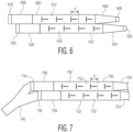
- FIG. 7 is a plan view diagram of radiating faces of two columns each with a shared feed on one or both sides. As in the example of FIG. 6 , more columns may be used each with a corresponding offset. A power divider may be used as shown in this FIG. 7 or separate feeds as in FIG. 6 .
- a first antenna is configured similar to that of FIG. 1 . The first antenna has a first waveguide 702 coupled to a first feed adapter 704 that tapers from the size of the waveguide to receive signals with a first polarization from a feed (not shown) at one end of the waveguide.
- the opposite end of the first waveguide 702 has a second feed adapter 708 that tapers in an orthogonal direction to receive signals with a second orthogonal polarization from a second feed 710.
- the feed adapters are configured to be and operate as reflectors of signals from the respective opposite feed adapter so that two standing waves are generated, one for each polarization.
- the first waveguide 702 has a radiating face 712 with a linear array of antenna elements for the two standing waves.
- a second waveguide 722 is also coupled to a first feed adapter 724 that tapers from the size of the waveguide to receive signals with the first polarization from a feed (not shown) at one end of the second waveguide 722.
- the opposite end of the second waveguide 722 has a second feed adapter 728 that tapers in an orthogonal direction to receive signals with the second orthogonal polarization from a second feed 730.
- a radiating face 732 of the second waveguide 732 has a linear array of antenna elements for the two standing waves.
- the second feed 710 of the first waveguide 702 and the second feed 730 of the second waveguide are both coupled to the same radio source 740 wherein both feeds are energized with the same signal.
- the opposite feed guides may also have the same or a different source.
- the elements are shown as linear slots in which the parallel linear slots are for one polarization direction and the perpendicular linear slots are for the other orthogonal polarization direction.
- the elements are in the form of parallel and perpendicular linear slots.
- the two waveguides are offset by a distance shown as d.
- each waveguide may use only the single shared feed to generate a standing wave in each waveguide that depends on the unique characteristics of the first and second feed, respectively.
- the described structures provide a compact antenna with dual polarization and high isolation between the polarization modes.
- Two orthogonal standing waves and two orthogonal current distributions may be generated simultaneously in a single waveguide.
- the radiation modes may be modified by changing the shape and dimensions of the antenna elements.
- the distance between the horizontal linear slots is given by the same guided wavelength calculated from the waveguide height and the distance between the vertical linear slots is given by the same guided wavelength calculated from the waveguide width.
- the functional wavelengths may be modified by filing the waveguide with different dielectric materials such as air, plastics, glasses, etc.
- the feeds are perpendicular to each other and the generated polarization modes are orthogonal to each other. These are both provided in a single waveguide.
- the trapezoidal feed adapters are used as reflectors for the orthogonal signal feed from the other side.
- the reflector generates a standing wave.
- the radiating face of the waveguide has linear slots that define the elements of the antenna array.
- the linear slots of one polarization mode can be placed parallel to the current distribution of the second polarization. This increases the isolation between the horizontal and vertical polarization.
Landscapes
- Variable-Direction Aerials And Aerial Arrays (AREA)
- Waveguide Aerials (AREA)
Abstract
Description
- Radar systems and communication systems send and receive radio signals via transmitting and receiving antennas. Some antennas are formed as a linear array of emitters to transmit and receive radio signals. The linear array allows for beamforming, in which the same signal is received with a different phase at each antenna element. The phase difference determines a direction for the beam. The linear array also allows for Multiple Input, Multiple Output (MIMO) techniques to create virtual antennas. The transmitted and received signals may have a specific polarization. A receiving antenna with a specific polarization may filter out signals that have a different polarization. For a radar, some objects can be detected more clearly with a particular polarization as compared to another polarization because those objects reflect a particular polarization better than other polarizations. Accordingly, a radio system may switch from one polarization to the other in order to isolate two different signals.
- A dual polarized antenna is described with a dual feed that is suitable for cross polarization isolation. In an embodiment, an antenna has a waveguide having a first rectangular face at an end, a second rectangular face at a second opposite end, and a radiating face between the first rectangular face and the second rectangular face. A first feed is configured to feed a first radio signal having a first polarization into the waveguide. A second feed is configured to feed a second radio signal having a second polarization orthogonal to the first polarization into the waveguide. A first plurality of polarized emitters on the radiating face are arranged in a first line along the radiating face to emit the first radio signal, and a second plurality of polarized emitters on the radiating face are arranged in a second line along the radiating face to emit the second radio signal.
- In an embodiment, the polarized emitters of the second plurality of polarized emitters are orthogonal to the polarized emitters of the first plurality of polarized emitters. In an embodiment, the polarized emitters of the first plurality of polarized emitters are formed as linear slots through the radiating face. In an embodiment, the radiating face comprises a conductive material and the linear slots are formed through the conductive material.
- In an embodiment, the polarized emitters of the second plurality of polarized emitters are formed as linear slots through the radiating face orthogonal to the linear slots of the polarized emitters of the first plurality of polarized emitters. In an embodiment, the waveguide has a waveguide axis that extends through the waveguide between the first rectangular face and the second rectangular face and wherein the linear slots of the first plurality of polarized emitters are parallel to the waveguide axis and the linear slots of second plurality of polarized emitters are perpendicular to the waveguide axis.
- In an embodiment, the polarized emitters of the first plurality of polarized emitters are separated by a distance of one guided wavelength of the first radio signal. In an embodiment, the linear slots of the first plurality of polarized emitters have a length of one half of a guided wavelength of the first radio signal.
- In embodiments, a first waveguide adapter is coupled between the first feed and the waveguide, wherein the first waveguide adapter is configured as a reflector of the second radio signal from the second feed into the waveguide, and a second waveguide adapter is coupled between the second feed and the waveguide, wherein the second waveguide adapter is configured as a reflector of the first radio signal from the first feed into the waveguide.
- In an embodiment, the first waveguide adapter is trapezoidal having a first rectangular cross section with unequal adjacent sides and the second waveguide adapter is trapezoidal having a second rectangular cross section with unequal adjacent sides. In an embodiment, a vertical side of a cross section of the first waveguide adapter is longer than a horizontal side of the cross section of the first waveguide adapter and a horizontal side of the cross section of the second waveguide adapter is longer than a vertical side of the cross section of the second waveguide adapter.
- In an embodiment, the waveguide is in a shape of a rectangular parallelepiped with parallel walls. In an embodiment, the first rectangular face and the second rectangular face are parallel and wherein a width of the first rectangular face is equal to the width of the second rectangular face. In an embodiment, the first rectangular face and the second rectangular face are square.
- In an embodiment, an apparatus includes a first rectangular waveguide having a first rectangular face at an end, a second rectangular face at a second opposite end, and a radiating face between the first rectangular face and the second rectangular face, a second rectangular waveguide having a first rectangular face at an end, a second rectangular face at a second opposite end, and a radiating face between the first rectangular face and the second rectangular face, a first feed coupled to the first rectangular face of the first rectangular waveguide, the first feed configured to feed a first radio signal having a first polarization into the first rectangular waveguide, a second feed coupled to the first rectangular face of the second rectangular waveguide, the second feed configured to feed a second radio signal having the first polarization into the second rectangular waveguide, a first plurality of polarized emitters on the radiating face of the first rectangular waveguide arranged in a line along the radiating face to emit the first radio signal, and a second plurality of polarized emitters on the radiating face arranged in a line along the radiating face to emit the second radio signal, wherein the first rectangular waveguide and the second rectangular waveguide are parallel and offset along an axis of the first rectangular waveguide.
- In an embodiment, the axis of the first rectangular waveguide is a longitudinal axis form the first rectangular face to the second rectangular face. In an embodiment, the first radio signal and the second radio signal are a same radio signal, wherein the first feed and the second feed are both coupled to a same radio source wherein the first feed and the second feed are energized with the same radio signal.
- An embodiment includes a third feed coupled to the first rectangular waveguide, the third feed configured to feed a third radio signal having a second polarization into the first rectangular waveguide, a first feed adapter coupled to the first feed of the first rectangular waveguide and coupled to the first rectangular waveguide, the first feed adapter configured to conduct the first radio signal and to reflect the third radio signal, a fourth feed coupled to the second rectangular waveguide to feed a fourth radio signal having a second polarization into the second rectangular waveguide and, a second feed adapter coupled to the first feed of the second rectangular waveguide and coupled to the second rectangular waveguide, the second feed adapter configured to conduct the second radio signal and to reflect the fourth radio signal.
- In an embodiment, the first rectangular waveguide comprises a solid dielectric material coated with a conductive material and wherein the first plurality of polarized emitters comprises linear slots formed through the conductive material.
- In an embodiment an antenna includes a rectangular waveguide having a first rectangular face at an end, a second rectangular face at a second opposite end, and a radiating face between the first rectangular face and the second rectangular face, the waveguide being conductive and filled with a dielectric; a first feed configured to feed a first radio signal having a horizontal polarization into the waveguide, a first feed adapter coupled to the first feed on one side and the waveguide on the other side, the first feed adapter being tapered from the size of the waveguide to the first feed, a second feed configured to feed a second radio signal having a vertical polarization into the waveguide, wherein the vertical polarization is orthogonal to the horizontal polarization, a second feed adapter coupled to the second feed on one side and the waveguide on the other side, the second feed adapter being tapered from the size of the waveguide to the second feed, so that the second feed adapter is a reflector of the first radio signal, a first plurality of polarized emitters arranged in a first line along the radiating face to emit the first radio signal, the first plurality of polarized emitters being configured as linear slots of equal length cut through the radiating face; and a second plurality of polarized emitters on the radiating face arranged in a second line along the radiating face to emit the second radio signal, the second plurality of polarized emitters being configured as linear slots of equal length cut through the radiating face perpendicular to the first plurality of polarized emitters.
- Other aspects in accordance with the invention will become apparent from the following detailed description, taken in conjunction with the accompanying drawings, illustrated by way of example of the principles of the invention
-
-
FIG. 1 is an isometric view of an example antenna. -
FIG. 2 is a topographical graph of current distribution from horizontal polarized waves on parallel linear slots of the antenna ofFIG. 1 . -
FIG. 3 is a topographical graph of current distribution from vertical polarized waves on parallel linear slots of the antenna ofFIG. 1 . -
FIG. 4 is a topographical graph of current distribution from horizontal polarized waves on perpendicular linear slots of the antenna ofFIG. 1 . -
FIG. 5 is a topographical graph of current distribution from vertical polarized waves on perpendicular linear slots of the antenna ofFIG. 1 . -
FIG. 6 is a plan view diagram of radiating faces of two columns each with a separate feed. -
FIG. 7 is a plan view diagram of radiating faces of two columns each with a shared feed on one side. - It will be readily understood that the components of the embodiments as generally described herein and illustrated in the appended figures could be arranged and designed in a wide variety of different configurations. Thus, the following more detailed description of various embodiments, as represented in the figures, is not intended to limit the scope of the present disclosure, but is merely representative of various embodiments. While the various aspects of the embodiments are presented in drawings, the drawings are not necessarily drawn to scale unless specifically indicated.
- The described embodiments are to be considered in all respects only as illustrative and not restrictive. The scope of the invention is, therefore, indicated by the appended claims rather than by this detailed description. All changes which come within the meaning and range of equivalency of the claims are to be embraced within their scope.
- Reference throughout this specification to features, advantages, or similar language does not imply that all of the features and advantages that may be realized with the present invention should be or are in any single embodiment of the invention. Rather, language referring to the features and advantages is understood to mean that a specific feature, advantage, or characteristic described in connection with an embodiment is included in at least one embodiment of the present invention. Thus, discussions of the features and advantages, and similar language, throughout this specification may, but do not necessarily, refer to the same embodiment.
- Furthermore, the described features, advantages, and characteristics of the invention may be combined in any suitable manner in one or more embodiments. One skilled in the relevant art will recognize, in light of the description herein, that the invention can be practiced without one or more of the specific features or advantages of a particular embodiment. In other instances, additional features and advantages may be recognized in certain embodiments that may not be present in all embodiments of the invention.
- Reference throughout this specification to "one embodiment," "an embodiment," or similar language means that a particular feature, structure, or characteristic described in connection with the indicated embodiment is included in at least one embodiment of the present invention. Thus, the phrases "in one embodiment," "in an embodiment," and similar language throughout this specification may, but do not necessarily, all refer to the same embodiment. As described herein, a single dual polarized antenna supports two simultaneous perpendicular polarizations, e.g. horizontal and vertical, to offer smaller dimensions, extremely low interference, reduced clutter reflections and more information about objects in a scene.
- To support both vertical and horizontal polarization, a vertical polarized antenna and a separate horizontal polarized antenna have been used. This provides excellent separation between the two signals. For a linear array, each antenna is coupled to a waveguide that provides the radio signal to the antenna elements and receives radio signals from each antenna element. The linear array allows for beamforming, in which the same signal is received with a different phase at each antenna element. The phase difference determines a direction for the beam. The linear array also allows for Multiple Input, Multiple Output (MIMO) techniques to create virtual antennas
- In embodiments, to support both vertical and horizontal polarization, a vertical polarized antenna and a separate horizontal polarized antenna may be combined in one compact waveguide using a separate feed for each antenna to provide excellent separation between the two signals. Alternatively, the antenna may be used for beamforming and MIMO communications. In embodiments, the antenna has two opposite feeding ports. This allows the feeds to switch between the two polarizations which can be used to reduce interference from other radars. The two feeds may be used to separate the horizontal polarized reflections from the vertical polarized reflections.
- Both modes may also be excited simultaneously due to the orthogonality of both waves propagating in both directions of the waveguide. The two feeding ports are independent of each other and the radiating slots for the two modes are independent of each other so that the characteristics for each polarization mode (such as the field of view (FOV), gain, sidelobes, etc.) can be designed independently. The antenna is able to be configured as two antennas in one structure. Even the center of phase of each polarization mode may be located separately, which is particularly useful for designing virtual elements of a MIMO radar. The described antenna has low losses due to the orthogonal feeding ports which function as a reflector for the orthogonal mode and provides very low leakage with high isolation.
-
FIG. 1 is an isometric view of anexample antenna 100 according to some embodiments. Theantenna 100 has awaveguide 102 in the shape of a rectangular parallelepiped with a firstrectangular face 104 for horizontal polarization at one end of the waveguide and a secondrectangular face 106, parallel to the firstrectangular face 104, for vertical polarization at an opposite end of the waveguide. The firstrectangular face 104 and the secondrectangular face 106 are parallel to each other and have the same dimension of length, y, and the same dimension of height, x. The length and height may be equal as for a square, as shown, or different as for a different rectangle to suit different implementations. The waveguide between the first and second rectangular faces has a rectangular cross section with four parallel walls or faces connecting the first and second rectangular faces. - The waveguide is fed from one side with first radio signal by a
horizontal waveguide adapter 110 at the firstrectangular face 104 and from the other side with a second radio signal by avertical waveguide adapter 112 at the secondrectangular face 106. Waves propagate along a waveguide axis. The waveguide axis extends through the waveguide between the firstrectangular face 104 and the secondrectangular face 106. The waveguide is cut on aradiating face 108 at what is shown as the top surface to have two sets of radiating slots described in more detail below. In some embodiments, some of the slots are linear slots and are elongated in a direction parallel to the waveguide axis and some of the slots are linear slots and are elongated in a direction perpendicular to the direction of propagation. - The
horizontal waveguide adapter 110 is coupled to the firstrectangular face 104 on one side and is coupled to a first feed, in this example, ahorizontal feed 116, on the other side, to feed thewaveguide 102 with a horizontal polarized wave through thehorizontal waveguide adapter 110. A first radio signal source (not shown) is coupled to thehorizontal feed 116 so that the horizontal feed feeds the first radio signal having a first polarization into the waveguide. The feed is shown here in a simplified form and represents a coupler between the horizontal waveguide adapter and a signal source. The signal source may include oscillators, mixers, couplers, feedhorns and polarizers to generate and carry the first radio signal to the waveguide adapter. Similarly, the secondrectangular face 106 is coupled to a second feed, in this example avertical feed 118 through thevertical waveguide adapter 112 from the other end. Like thehorizontal feed 116, thevertical feed 118 represents a coupler. A horizontal polarized signal is injected by thehorizontal feed 116 into the waveguide. A second radio signal source (not shown) is coupled to thevertical feed 118. The second feed feeds the second radio signal having a second polarization into the waveguide. The waveguide adapters have a trapezoidal form from the respective rectangular face of the waveguide with a transition to a respective feed. Thevertical feed 118 allows only vertical polarized waves to pass through. In this way, the vertical feed reflects the wave coming from the opposite 90° rotatedhorizontal feed 116 back to thehorizontal feed 116. Similarly, at the opposite end of the waveguide, the 90° rotatedvertical waveguide adapter 112, being trapezoidal, will reflect back the wave coming from thehorizontal waveguide adapter 110 because it has a rotated polarization. Using a waveguide with a square cross section and waveguide adapters that taper from the waveguide to respective orthogonal feeds, the isolation between the twofeeds - As shown, in some embodiments, the first waveguide adapter, e.g. the
horizontal waveguide adapter 110, is coupled between thefirst feed 116 and thewaveguide 102. The first waveguide adapter is also configured to be a reflector of the second radio signal from thesecond feed 118 into the waveguide. The second waveguide adapter, e.g. thevertical waveguide adapter 112, is coupled between thesecond feed 118 and thewaveguide 102. The second waveguide adapter is configured to be a reflector of the first radio signal from thefirst feed 116 into thewaveguide 102. In embodiments, the first waveguide adapter and the second waveguide adapter are trapezoidal with respective rectangular cross sections. The rectangular cross sections have unequal adjacent sides to carry the horizontal or vertical polarization. As shown, a vertical side of the cross section of the first waveguide feed is longer than a horizontal side of the cross section of the first waveguide feed. In a similar way, a horizontal side of the cross section of the second waveguide feed is longer than a vertical side of the cross section of the second waveguide feed. The first rectangular cross section with unequal adjacent sides may have the same dimensions as the second rectangular cross section with unequal adjacent sides but rotated by a right angle. - The reflection from each end of the waveguide allows two standing waves to be generated inside the waveguide which will excite the linear slots. With two simultaneous standing waves with different forms or patterns, two different surface current distributions will co-exist at each of the four walls of the waveguide including the radiating
face 108 shown as the top surface which includes the radiating slots. A first set ofpolarized emitters 120 are formed in the top surface as linear slots that are cut through the surface of the waveguide and extend parallel to the waveguide axis. These linear slots all extend in a parallel direction and may be linearly aligned or placed in offset positions to suit particular implementations. The first set ofpolarized emitters 120 are for horizontal polarized radiation and may operate as transmit elements, receive elements, or both. The first set of polarized emitters are configured to emit the first radio signal with the first polarization. As shown, the first set of polarized emitters are arranged in a first line along the radiatingface 108 of the waveguide to form a linear antenna element array. In some embodiments, the emitting elements are all the same length and width, as shown, in order to simplify the use of the antenna. - A second set of
polarized emitters 122 are formed in the radiatingface 108 as linear slots that are cut through the surface of the top surface of the waveguide and extend perpendicular to the propagation axis of the waveguide. The second set ofpolarized emitters 122 are arranged in a second line along the radiatingface 108 of the waveguide to form another linear antenna element array for vertical polarized radiation. The linear slots are elongated and extend perpendicular to the first set of polarized emitters and perpendicular to the axis of the waveguide to cut the current distribution at its maximum. The second set of polarized emitters are configured to emit the second radio signal with the second polarization. The second set of polarized emitters radiate due to the generated standing wave from thevertical feed 118. The linear slots of the first set ofpolarized emitters 120, parallel to the waveguide, are parallel to the direction of the other current distribution generated by the vertical feed. The linear slots of the first set of polarized emitters may be placed where that current density generated by the second feed is a minimum in order not to disturb the vertical polarization mode and cause unwanted vertical polarized radiation. - Each of the two sets of polarized emitters may be configured as a separate array of antenna elements. The first set of
polarized emitters 120 are configured as antenna elements parallel to the waveguide for horizontal polarization. These may be separated by a distance equal to one guided wavelength of the guided wavelength received from the horizontal feed 116 (shown as "b" inFIG. 1 ). A waveguide filled with a material (rather than air) can be used to reduce the separation distance between those slots. The second set ofpolarized emitters 122 are configured as perpendicular linear slots for vertical polarization and may be separated by a distance equal to one guided wavelength of the guided wavelength received from the vertical feed 118 (shown as "a" infigure 1 ). A waveguide filled with a material (rather than air) can be used to reduce the separation distance between those slots. In some embodiments, the linear slots have a length one half of a guided wavelength or λ0 /2, where λ0 is the free-space guided wavelength of the antenna operating frequency. The radiatingface 108 is at the top with respect to the drawing figure but, in use, this radiating face may be oriented in any direction. For vehicle operations, the radiating face may be directed toward a front of the vehicle to detect objects in front of the vehicle or to the rear or sides. - The
waveguide 102 and thewaveguide adapters feeds -
FIG. 2 is a topographical graph of current distribution from horizontal polarized waves on parallel linear slots. In particular, the current distribution is shown on the radiatingface 108 in response to being energized by horizontal polarized waves from thehorizontal feed 116. Only the response of the parallel linear slots that comprise the first set ofpolarized emitters 120 are shown. The emitter positions correspond to the power peak positions. The power peaks exist at a distance of one guided wavelength of the horizontal polarized radio signal. The axes x and y ofFIG. 2 are coordinate axes and are not directly relate to the coordinate axes ofFIG. 1 . -
FIG. 3 is a topographical graph of current distribution from vertical polarized waves on parallel linear slots. In particular, the current distribution is shown superimposed on the radiatingface 108 of the waveguide for the same parallel linear slots of the first set ofpolarized emitters 120 in response to being energized with vertical polarized waves from thevertical feed 118. The horizontal polarization slots are placed at the spots of the radiatingface 108 where the current distribution generated by thevertical feed 118 has weak power in order to reduce the cross polarization. Cross polarization comes from the vertically polarized emission due to the horizontal polarized slots. -
FIG. 4 is a topographical graph of current distribution from horizontal polarized waves on perpendicular linear slots. In particular, the current distribution is shown superimposed on the radiatingface 108 of the waveguide with only perpendicular slots that comprise the second set ofpolarized emitters 122 in response to being energized with horizontal polarized waves from thehorizontal feed 116. The vertical polarization slots are placed at the spots of the radiatingface 108 where the current distribution generated by thehorizontal feed 116 has weak power in order to reduce the cross polarization. Cross polarization in this case is the horizontal polarized emission due to vertical polarized slots. -
FIG. 5 is a topographical graph of current distribution from vertical polarized waves on perpendicular linear slots. In particular, the current distribution is shown superimposed on the radiatingface 108 of the waveguide with only perpendicular slots that comprise the second set ofpolarized emitters 122 in response to being energized with vertical polarized waves from thevertical feed 118. The slot positions correspond to the power peak positions of the current distribution from thevertical feed 118. The power peaks exist at a distance of one guided wavelength of the guided wavelength of the vertical polarized radio signal. - The linear slots for horizontal polarized radiation are placed perpendicular to cut the current distribution of the horizontal polarization energization signal at its maximum as shown in
FIG. 2 . At the same time, the parallel linear slots are parallel to the direction of flow of the other current distribution generated by the vertical feed as shown inFIG. 3 . The parallel linear slots can be placed where that current is a minimum in order not to disturb the other mode and cause unwanted vertical polarized radiation. As a result, a high polarization purity, also referred to a good axial ratio is provided. In addition, the antenna provides a high isolation between the vertical and horizontal polarization signals. In some embodiments, the isolation is more than -34 dB. - The structures described herein may be modified to suit different purposes. In some embodiments, the aperture size as determined, for example, by the number of parallel linear slots can be changed independently of the aperture size as determined by the number of perpendicular slots by changing the waveguide dimensions. Similarly, the number of linear slots of the vertical polarized antenna can be changed independently from that of the horizontal polarized antenna by changing the waveguide dimensions. In some embodiments, the aperture center of the horizontal polarized antenna as determined, for example, by the phase center of the array, or of the vertical polarized antenna may be changed independently of the other. This is in part because the location of the standing wave peak for a respective feed depends on the waveguide dimensions.
- The location of the side lobes of the radiation pattern for both polarizations may also be changed by changing the cross-sectional dimensions of the waveguide, for example the x and y dimensions of the
faces - In some embodiments, a tapering function may be applied to the linear slots of the antenna array by reducing the length of each slot by an amount that increases with distance from the phase center. The length of a slot determines its relative radiating power.
- The signal feeds may be modified to suit different applications. As shown each waveguide may receive a different feed on each side so that the antenna is fed by two independent sources. Alternatively a single source may be coupled to a two-port power divider to split the input power between the first feed and the second feed. A waveguide twist may be used to rotate the polarization of one of the feeds.
- In some embodiments, an array can be built by combining two or more columns, each of which provide dual (horizontal and vertical) polarization. Stacking two waveguides of a type as shown in
FIG. 1 , allows any ambiguity from grating lobes to be resolved and provides additional operational modes that may allow for enhanced resolution or signal fidelity. - In some embodiments, the antenna radiates a pattern which presents grating lobes in one plane of the radiation pattern from the antenna. This is more likely when a single array of linear slots is used as the polarized emitters. The grating lobes may result in areas in which the angular position of a target in the scene cannot be unambiguously resolved. Currently, there are signal processing techniques that are able to resolve the ambiguity. Modifications may also be made to the physical structure of the antenna to overcome the grating lobes.
- As an example, two linear arrays of polarized emitters may be used. Some techniques for resolving the ambiguities in the grating lobe regions are described below. In some embodiments, the phase difference between the horizontal and vertical polarized received signals resolves the ambiguities. The phase difference between the horizontal and vertical polarized antenna is given by 0 which may be defined as:

where θ is the impinging angle of the received signals at the antenna array and d is the distance between the phase centers of the two antennas, the vertical polarized antenna, and the horizontal polarized antenna, respectively. - Whether the object is located in a lobe at the main field of view of the radar receiver or another lobe, the object will appear at both locations of the detection map and for both antennas. By processing the phase shift between the two antennas for that target, the target can be located within the field of view and tracked. Alternatively, the object can be located outside the field of view and ignored. However, in the rare instance of two objects with the same range, speed, and azimuth angle, there may still be ambiguity.
- In some embodiments, the phase shift between the received signal with a same polarization at different antennas with different feeds resolves the ambiguity. This approach uses two or more neighboring antennas that have the same polarization but that have separated feeds. The phase shift between the received signals is used to resolve the ambiguity. By introducing a displacement, d, between the phase centers of two or more columns or linear arrays, the object can be located within or outside the radar's field of view (FoV).
-
FIG. 6 is a plan view diagram of radiating faces of two columns each with a separate feed. A two antennas are configured similar to that ofFIG. 1 but are offset by a distance d. While two columns are shown, more columns may be used each with a corresponding offset. The first antenna has afirst waveguide 602 coupled to afirst feed adapter 604. Thefirst feed adapter 604 is coupled to thefirst waveguide 602 on one side and is coupled to afeed 606 on the other side. Thefirst feed adapter 604 tapers from the size of the waveguide to receive signals with a first polarization from thefeed 606 at the other end of the waveguide. The opposite end of thewaveguide 602 has asecond feed adapter 608 that is coupled to the that tapers in an orthogonal direction to receive signals with a second orthogonal polarization from asecond feed 610. The feed adapters are configured to be reflectors of signals from the respective opposite feed adapter so that two standing waves are generated, one for each polarization. Thewaveguide 602 has a radiatingface 612 with a linear array of antenna elements for the two standing waves. The elements are shown as linear slots in which the parallel linear slots are for one polarization direction and the perpendicular linear slots are for the other orthogonal polarization direction. - A
second waveguide 622 is also coupled to afirst feed adapter 624 that tapers from the size of the waveguide to receive signals with the first polarization from afirst feed 626 at one end of thesecond waveguide 622. Thefirst feed adapter 624 is coupled to thesecond waveguide 622 on one side and is coupled to thefeed 626 on the other side. The opposite end of thesecond waveguide 622 has asecond feed adapter 628 that tapers in an orthogonal direction to receive signals with the second orthogonal polarization from asecond feed 630. A radiatingface 632 of thesecond waveguide 632 has a linear array of antenna elements for the two standing waves. The elements are in the form of parallel linear slots and perpendicular linear slots. - The two waveguides are offset by a distance shown as d. The polarized emitters are configured in the same locations on the respective radiating faces, such that the distance of one or more of the linear slots from the respective feed horn is the same on both radiating faces of the two waveguides. The offset causes the linear slots of one radiating face to be offset by the distance d from the corresponding linear slots of the other radiating face. A direct calculation may be made to process the phase difference between the signals received at elements of the
first waveguide 602 and corresponding elements of thesecond waveguide 622. Alternatively, more advanced calculations may be used to process the phase from multiple Rx antennas (e.g. by Fast Fourier Transform (FFT)) and then removing the ambiguity. - The configuration of
FIG. 6 shows stacked arrays each with two independent feeds for a total of four signal feeds, two for the vertical polarization on one side of the waveguides and two for the horizontal configuration on the other side of the waveguide. In alternative embodiments, one or more of the signal feeds may be combined. In some embodiments, the phase shift between two displaced antennas with the same feed resolves the grating lobes ambiguity. The received signals from two or more columns that have the same feed, e.g. a shared feed, may be combined. -
FIG. 7 is a plan view diagram of radiating faces of two columns each with a shared feed on one or both sides. As in the example ofFIG. 6 , more columns may be used each with a corresponding offset. A power divider may be used as shown in thisFIG. 7 or separate feeds as inFIG. 6 . A first antenna is configured similar to that ofFIG. 1 . The first antenna has afirst waveguide 702 coupled to afirst feed adapter 704 that tapers from the size of the waveguide to receive signals with a first polarization from a feed (not shown) at one end of the waveguide. The opposite end of thefirst waveguide 702 has asecond feed adapter 708 that tapers in an orthogonal direction to receive signals with a second orthogonal polarization from asecond feed 710. The feed adapters are configured to be and operate as reflectors of signals from the respective opposite feed adapter so that two standing waves are generated, one for each polarization. Thefirst waveguide 702 has a radiatingface 712 with a linear array of antenna elements for the two standing waves. - A
second waveguide 722 is also coupled to afirst feed adapter 724 that tapers from the size of the waveguide to receive signals with the first polarization from a feed (not shown) at one end of thesecond waveguide 722. The opposite end of thesecond waveguide 722 has asecond feed adapter 728 that tapers in an orthogonal direction to receive signals with the second orthogonal polarization from asecond feed 730. A radiatingface 732 of thesecond waveguide 732 has a linear array of antenna elements for the two standing waves. Thesecond feed 710 of thefirst waveguide 702 and thesecond feed 730 of the second waveguide are both coupled to thesame radio source 740 wherein both feeds are energized with the same signal. The opposite feed guides may also have the same or a different source. The elements are shown as linear slots in which the parallel linear slots are for one polarization direction and the perpendicular linear slots are for the other orthogonal polarization direction. The elements are in the form of parallel and perpendicular linear slots. The two waveguides are offset by a distance shown as d. - The two columns, as shown, or more columns may be combined for midrange and long-range applications in any of a variety of different ways to suit different applications. By combining two signals and compensating for the phase shift between the two columns based on the distance, d, the ambiguities of a single column can be removed. Alternatively, each waveguide may use only the single shared feed to generate a standing wave in each waveguide that depends on the unique characteristics of the first and second feed, respectively.
- The described structures provide a compact antenna with dual polarization and high isolation between the polarization modes. Two orthogonal standing waves and two orthogonal current distributions may be generated simultaneously in a single waveguide. The radiation modes may be modified by changing the shape and dimensions of the antenna elements. In some embodiments, the distance between the horizontal linear slots is given by the same guided wavelength calculated from the waveguide height and the distance between the vertical linear slots is given by the same guided wavelength calculated from the waveguide width. The functional wavelengths may be modified by filing the waveguide with different dielectric materials such as air, plastics, glasses, etc.
- As described for some embodiments, the feeds are perpendicular to each other and the generated polarization modes are orthogonal to each other. These are both provided in a single waveguide. The trapezoidal feed adapters are used as reflectors for the orthogonal signal feed from the other side. The reflector generates a standing wave. The radiating face of the waveguide has linear slots that define the elements of the antenna array. The linear slots of one polarization mode can be placed parallel to the current distribution of the second polarization. This increases the isolation between the horizontal and vertical polarization.
- Although specific embodiments of the invention have been described and illustrated, the invention is not to be limited to the specific forms or arrangements of parts so described and illustrated. The scope of the invention is to be defined by the claims appended hereto and their equivalents.
Claims (15)
- An antenna comprising:a waveguide having a first rectangular face at an end, a second rectangular face at a second opposite end, and a radiating face between the first rectangular face and the second rectangular face;a first feed configured to feed a first radio signal having a first polarization into the waveguide;a second feed configured to feed a second radio signal having a second polarization orthogonal to the first polarization into the waveguide;a first plurality of polarized emitters on the radiating face arranged in a first line along the radiating face to emit the first radio signal; anda second plurality of polarized emitters on the radiating face arranged in a second line along the radiating face to emit the second radio signal.
- The antenna of claim 1, wherein the polarized emitters of the second plurality of polarized emitters are orthogonal to the polarized emitters of the first plurality of polarized emitters.
- The antenna of any of claims 1 to 2, wherein the polarized emitters of the first plurality of polarized emitters are formed as linear slots through the radiating face.
- The antenna of claim 3, wherein the radiating face comprises a conductive material and the linear slots are formed through the conductive material.
- The antenna of claim 3, wherein the polarized emitters of the second plurality of polarized emitters are linear slots formed through the radiating face orthogonal to the linear slots of the polarized emitters of the first plurality of polarized emitters.
- The antenna of claim 5, wherein the waveguide has a waveguide axis that extends through the waveguide between the first rectangular face and the second rectangular face and wherein the linear slots of the first plurality of polarized emitters are parallel to the waveguide axis and the linear slots of second plurality of polarized emitters are perpendicular to the waveguide axis.
- The antenna of any of claims 3 to 6, wherein the polarized emitters of the first plurality of polarized emitters are separated by a distance of one guided wavelength of the first radio signal.
- The antenna of any of claims 3 to 7, wherein the linear slots of the first plurality of polarized emitters have a length of one half of a guided wavelength of the first radio signal.
- The antenna of any of claims 1 to 8, further comprising:a first waveguide adapter coupled between the first feed and the waveguide, wherein the first waveguide adapter is configured as a reflector of the second radio signal from the second feed into the waveguide; anda second waveguide adapter coupled between the second feed and the waveguide, wherein the second waveguide adapter is configured as a reflector of the first radio signal from the first feed into the waveguide.
- The antenna of claim 9, wherein the first waveguide adapter is trapezoidal having a first rectangular cross section with unequal adjacent sides and the second waveguide adapter is trapezoidal having a second rectangular cross section with unequal adjacent sides.
- The antenna of claim 10 or 11, wherein a vertical side of a cross section of the first waveguide adapter is longer than a horizontal side of the cross section of the first waveguide adapter and a horizontal side of the cross section of the second waveguide adapter is longer than a vertical side of the cross section of the second waveguide adapter.
- The antenna of any of claims 1 to 11, wherein the waveguide is in a shape of a rectangular parallelepiped with parallel walls.
- The antenna of any of claims 1 to 12, wherein the first rectangular face and the second rectangular face are parallel and wherein a width of the first rectangular face is equal to the width of the second rectangular face.
- The antenna of claim 13, wherein the first rectangular face and the second rectangular face are square.
- An apparatus comprising:a first rectangular waveguide having a first rectangular face at an end, a second rectangular face at a second opposite end, and a radiating face between the first rectangular face and the second rectangular face;a second rectangular waveguide having a first rectangular face at an end, a second rectangular face at a second opposite end, and a radiating face between the first rectangular face and the second rectangular face;a first feed coupled to the first rectangular face of the first rectangular waveguide, the first feed configured to feed a first radio signal having a first polarization into the first rectangular waveguide;a second feed coupled to the first rectangular face of the second rectangular waveguide, the second feed configured to feed a second radio signal having the first polarization into the second rectangular waveguide;a first plurality of polarized emitters on the radiating face of the first rectangular waveguide arranged in a line along the radiating face to emit the first radio signal; anda second plurality of polarized emitters on the radiating face arranged in a line along the radiating face to emit the second radio signal,wherein the first rectangular waveguide and the second rectangular waveguide are parallel and offset along an axis of the first rectangular waveguide.
Applications Claiming Priority (1)
| Application Number | Priority Date | Filing Date | Title |
|---|---|---|---|
| US17/724,102 US12537317B2 (en) | 2022-04-19 | 2022-04-19 | Dual polarized antenna with dual feed and cross polarization isolation |
Publications (2)
| Publication Number | Publication Date |
|---|---|
| EP4266501A1 true EP4266501A1 (en) | 2023-10-25 |
| EP4266501B1 EP4266501B1 (en) | 2025-09-10 |
Family
ID=85980508
Family Applications (1)
| Application Number | Title | Priority Date | Filing Date |
|---|---|---|---|
| EP23167074.6A Active EP4266501B1 (en) | 2022-04-19 | 2023-04-06 | Dual polarized antenna with dual feed and cross polarization isolation |
Country Status (2)
| Country | Link |
|---|---|
| US (1) | US12537317B2 (en) |
| EP (1) | EP4266501B1 (en) |
Citations (4)
| Publication number | Priority date | Publication date | Assignee | Title |
|---|---|---|---|---|
| US3348227A (en) * | 1964-08-03 | 1967-10-17 | Gen Precision Inc | Cross-polarized microwave antenna |
| US3680139A (en) * | 1970-08-17 | 1972-07-25 | Westinghouse Electric Corp | Common antenna aperture having polarization diversity |
| US5541612A (en) * | 1991-11-29 | 1996-07-30 | Telefonaktiebolaget Lm Ericsson | Waveguide antenna which includes a slotted hollow waveguide |
| KR102224626B1 (en) * | 2019-12-09 | 2021-03-05 | 경남대학교 산학협력단 | Waveguide slot array antenna |
Family Cites Families (7)
| Publication number | Priority date | Publication date | Assignee | Title |
|---|---|---|---|---|
| US2982960A (en) * | 1958-08-29 | 1961-05-02 | Hughes Aircraft Co | Arbitrarily polarized slot radiator |
| US8098189B1 (en) * | 2008-09-23 | 2012-01-17 | Rockwell Collins, Inc. | Weather radar system and method using dual polarization antenna |
| JP2012204975A (en) | 2011-03-24 | 2012-10-22 | Sumitomo Electric Ind Ltd | Waveguide slot antenna |
| JP2013106301A (en) | 2011-11-16 | 2013-05-30 | Mitsubishi Electric Corp | Waveguide slot array antenna device |
| CN110867644B (en) | 2019-11-11 | 2021-01-19 | 中国电子科技集团公司第十四研究所 | Dual-band multi-polarization common-caliber coaxial waveguide slot antenna |
| EP3929622B1 (en) | 2020-06-25 | 2024-08-07 | NXP USA, Inc. | Radar system |
| US11815589B2 (en) | 2020-08-28 | 2023-11-14 | Nxp B.V. | Multiple-mode radar with resolution of spatial ambiguity |
-
2022
- 2022-04-19 US US17/724,102 patent/US12537317B2/en active Active
-
2023
- 2023-04-06 EP EP23167074.6A patent/EP4266501B1/en active Active
Patent Citations (4)
| Publication number | Priority date | Publication date | Assignee | Title |
|---|---|---|---|---|
| US3348227A (en) * | 1964-08-03 | 1967-10-17 | Gen Precision Inc | Cross-polarized microwave antenna |
| US3680139A (en) * | 1970-08-17 | 1972-07-25 | Westinghouse Electric Corp | Common antenna aperture having polarization diversity |
| US5541612A (en) * | 1991-11-29 | 1996-07-30 | Telefonaktiebolaget Lm Ericsson | Waveguide antenna which includes a slotted hollow waveguide |
| KR102224626B1 (en) * | 2019-12-09 | 2021-03-05 | 경남대학교 산학협력단 | Waveguide slot array antenna |
Non-Patent Citations (1)
| Title |
|---|
| GOEBELS ET AL: "Four Independent Beams from a Single Linear Array", IEEE TRANSACTIONS ON ANTENNAS AND PROPAGATION,, vol. AP-13, no. 5, 1 September 1965 (1965-09-01), pages 683 - 691, XP001382062 * |
Also Published As
| Publication number | Publication date |
|---|---|
| EP4266501B1 (en) | 2025-09-10 |
| US20230335919A1 (en) | 2023-10-19 |
| US12537317B2 (en) | 2026-01-27 |
Similar Documents
| Publication | Publication Date | Title |
|---|---|---|
| US7961153B2 (en) | Integrated waveguide antenna and array | |
| US12451596B2 (en) | Microstrip antenna, antenna array, radar, and vehicle | |
| US7656358B2 (en) | Antenna operable at two frequency bands simultaneously | |
| US7554505B2 (en) | Integrated waveguide antenna array | |
| US7847749B2 (en) | Integrated waveguide cavity antenna and reflector RF feed | |
| US7656359B2 (en) | Apparatus and method for antenna RF feed | |
| EP3488495B1 (en) | Antenna and radar system that include a polarization-rotating layer | |
| US20050140559A1 (en) | Hexagonal array structure of dielectric rod to shape flat-topped element pattern | |
| US5467100A (en) | Slot-coupled fed dual circular polarization TEM mode slot array antenna | |
| EP0126626B1 (en) | Resonant waveguide aperture manifold | |
| EP0390350B1 (en) | Low cross-polarization radiator of circularly polarized radiation | |
| CN101479887A (en) | Integrated waveguide antenna and array | |
| JP3731354B2 (en) | Antenna device and transmitting / receiving device | |
| US4348679A (en) | Multi-mode dual-feed array radar antenna | |
| IL243105A (en) | Source for parabolic antenna | |
| EP3271968A1 (en) | An amplitude comparison monopulse radar system | |
| CN112909513A (en) | Dual-polarized waveguide slot array antenna on annular disc and combined antenna | |
| US12341250B1 (en) | Offset-fed reflector parallel plate antenna apparatus | |
| US3247512A (en) | Microwave antenna | |
| EP4266501B1 (en) | Dual polarized antenna with dual feed and cross polarization isolation | |
| JPH1188043A (en) | Antenna device | |
| CN112909557B (en) | Waveguide slot array antenna on annular disc and combined antenna | |
| CN108539437B (en) | Dual-frequency dual-polarization common-caliber waveguide slot array antenna | |
| CN117578074A (en) | Antenna system and radar equipment | |
| JPH10327014A (en) | Antenna device |
Legal Events
| Date | Code | Title | Description |
|---|---|---|---|
| STAA | Information on the status of an ep patent application or granted ep patent |
Free format text: STATUS: THE APPLICATION HAS BEEN PUBLISHED |
|
| PUAI | Public reference made under article 153(3) epc to a published international application that has entered the european phase |
Free format text: ORIGINAL CODE: 0009012 |
|
| AK | Designated contracting states |
Kind code of ref document: A1 Designated state(s): AL AT BE BG CH CY CZ DE DK EE ES FI FR GB GR HR HU IE IS IT LI LT LU LV MC ME MK MT NL NO PL PT RO RS SE SI SK SM TR |
|
| STAA | Information on the status of an ep patent application or granted ep patent |
Free format text: STATUS: REQUEST FOR EXAMINATION WAS MADE |
|
| 17P | Request for examination filed |
Effective date: 20240425 |
|
| RBV | Designated contracting states (corrected) |
Designated state(s): AL AT BE BG CH CY CZ DE DK EE ES FI FR GB GR HR HU IE IS IT LI LT LU LV MC ME MK MT NL NO PL PT RO RS SE SI SK SM TR |
|
| GRAP | Despatch of communication of intention to grant a patent |
Free format text: ORIGINAL CODE: EPIDOSNIGR1 |
|
| STAA | Information on the status of an ep patent application or granted ep patent |
Free format text: STATUS: GRANT OF PATENT IS INTENDED |
|
| RIC1 | Information provided on ipc code assigned before grant |
Ipc: H01Q 1/32 20060101ALN20250515BHEP Ipc: H01P 5/02 20060101ALN20250515BHEP Ipc: H01Q 25/00 20060101ALI20250515BHEP Ipc: H01Q 21/00 20060101AFI20250515BHEP |
|
| INTG | Intention to grant announced |
Effective date: 20250605 |
|
| GRAS | Grant fee paid |
Free format text: ORIGINAL CODE: EPIDOSNIGR3 |
|
| GRAA | (expected) grant |
Free format text: ORIGINAL CODE: 0009210 |
|
| STAA | Information on the status of an ep patent application or granted ep patent |
Free format text: STATUS: THE PATENT HAS BEEN GRANTED |
|
| AK | Designated contracting states |
Kind code of ref document: B1 Designated state(s): AL AT BE BG CH CY CZ DE DK EE ES FI FR GB GR HR HU IE IS IT LI LT LU LV MC ME MK MT NL NO PL PT RO RS SE SI SK SM TR |
|
| REG | Reference to a national code |
Ref country code: GB Ref legal event code: FG4D |
|
| REG | Reference to a national code |
Ref country code: CH Ref legal event code: EP |
|
| REG | Reference to a national code |
Ref country code: DE Ref legal event code: R096 Ref document number: 602023006468 Country of ref document: DE |
|
| REG | Reference to a national code |
Ref country code: IE Ref legal event code: FG4D |
|
| PG25 | Lapsed in a contracting state [announced via postgrant information from national office to epo] |
Ref country code: NO Free format text: LAPSE BECAUSE OF FAILURE TO SUBMIT A TRANSLATION OF THE DESCRIPTION OR TO PAY THE FEE WITHIN THE PRESCRIBED TIME-LIMIT Effective date: 20251210 |
|
| REG | Reference to a national code |
Ref country code: LT Ref legal event code: MG9D |
|
| PG25 | Lapsed in a contracting state [announced via postgrant information from national office to epo] |
Ref country code: FI Free format text: LAPSE BECAUSE OF FAILURE TO SUBMIT A TRANSLATION OF THE DESCRIPTION OR TO PAY THE FEE WITHIN THE PRESCRIBED TIME-LIMIT Effective date: 20250910 |
|
| REG | Reference to a national code |
Ref country code: NL Ref legal event code: MP Effective date: 20250910 |
|
| PG25 | Lapsed in a contracting state [announced via postgrant information from national office to epo] |
Ref country code: HR Free format text: LAPSE BECAUSE OF FAILURE TO SUBMIT A TRANSLATION OF THE DESCRIPTION OR TO PAY THE FEE WITHIN THE PRESCRIBED TIME-LIMIT Effective date: 20250910 |
|
| PG25 | Lapsed in a contracting state [announced via postgrant information from national office to epo] |
Ref country code: GR Free format text: LAPSE BECAUSE OF FAILURE TO SUBMIT A TRANSLATION OF THE DESCRIPTION OR TO PAY THE FEE WITHIN THE PRESCRIBED TIME-LIMIT Effective date: 20251211 |
|
| PG25 | Lapsed in a contracting state [announced via postgrant information from national office to epo] |
Ref country code: SE Free format text: LAPSE BECAUSE OF FAILURE TO SUBMIT A TRANSLATION OF THE DESCRIPTION OR TO PAY THE FEE WITHIN THE PRESCRIBED TIME-LIMIT Effective date: 20250910 |
|
| PG25 | Lapsed in a contracting state [announced via postgrant information from national office to epo] |
Ref country code: LV Free format text: LAPSE BECAUSE OF FAILURE TO SUBMIT A TRANSLATION OF THE DESCRIPTION OR TO PAY THE FEE WITHIN THE PRESCRIBED TIME-LIMIT Effective date: 20250910 |
|
| PG25 | Lapsed in a contracting state [announced via postgrant information from national office to epo] |
Ref country code: PL Free format text: LAPSE BECAUSE OF FAILURE TO SUBMIT A TRANSLATION OF THE DESCRIPTION OR TO PAY THE FEE WITHIN THE PRESCRIBED TIME-LIMIT Effective date: 20250910 Ref country code: BG Free format text: LAPSE BECAUSE OF FAILURE TO SUBMIT A TRANSLATION OF THE DESCRIPTION OR TO PAY THE FEE WITHIN THE PRESCRIBED TIME-LIMIT Effective date: 20250910 |
|
| PG25 | Lapsed in a contracting state [announced via postgrant information from national office to epo] |
Ref country code: RS Free format text: LAPSE BECAUSE OF FAILURE TO SUBMIT A TRANSLATION OF THE DESCRIPTION OR TO PAY THE FEE WITHIN THE PRESCRIBED TIME-LIMIT Effective date: 20251210 |
|
| PG25 | Lapsed in a contracting state [announced via postgrant information from national office to epo] |
Ref country code: ES Free format text: LAPSE BECAUSE OF FAILURE TO SUBMIT A TRANSLATION OF THE DESCRIPTION OR TO PAY THE FEE WITHIN THE PRESCRIBED TIME-LIMIT Effective date: 20250910 |
|
| REG | Reference to a national code |
Ref country code: AT Ref legal event code: MK05 Ref document number: 1836909 Country of ref document: AT Kind code of ref document: T Effective date: 20250910 |
|
| PG25 | Lapsed in a contracting state [announced via postgrant information from national office to epo] |
Ref country code: NL Free format text: LAPSE BECAUSE OF FAILURE TO SUBMIT A TRANSLATION OF THE DESCRIPTION OR TO PAY THE FEE WITHIN THE PRESCRIBED TIME-LIMIT Effective date: 20250910 |
|
| PG25 | Lapsed in a contracting state [announced via postgrant information from national office to epo] |
Ref country code: SM Free format text: LAPSE BECAUSE OF FAILURE TO SUBMIT A TRANSLATION OF THE DESCRIPTION OR TO PAY THE FEE WITHIN THE PRESCRIBED TIME-LIMIT Effective date: 20250910 |
|
| PG25 | Lapsed in a contracting state [announced via postgrant information from national office to epo] |
Ref country code: AT Free format text: LAPSE BECAUSE OF FAILURE TO SUBMIT A TRANSLATION OF THE DESCRIPTION OR TO PAY THE FEE WITHIN THE PRESCRIBED TIME-LIMIT Effective date: 20250910 |
|
| PG25 | Lapsed in a contracting state [announced via postgrant information from national office to epo] |
Ref country code: IT Free format text: LAPSE BECAUSE OF FAILURE TO SUBMIT A TRANSLATION OF THE DESCRIPTION OR TO PAY THE FEE WITHIN THE PRESCRIBED TIME-LIMIT Effective date: 20250910 |
|
| PG25 | Lapsed in a contracting state [announced via postgrant information from national office to epo] |
Ref country code: IS Free format text: LAPSE BECAUSE OF FAILURE TO SUBMIT A TRANSLATION OF THE DESCRIPTION OR TO PAY THE FEE WITHIN THE PRESCRIBED TIME-LIMIT Effective date: 20260110 |
|
| PGFP | Annual fee paid to national office [announced via postgrant information from national office to epo] |
Ref country code: FR Payment date: 20260320 Year of fee payment: 4 |
|
| PG25 | Lapsed in a contracting state [announced via postgrant information from national office to epo] |
Ref country code: CZ Free format text: LAPSE BECAUSE OF FAILURE TO SUBMIT A TRANSLATION OF THE DESCRIPTION OR TO PAY THE FEE WITHIN THE PRESCRIBED TIME-LIMIT Effective date: 20250910 Ref country code: PT Free format text: LAPSE BECAUSE OF FAILURE TO SUBMIT A TRANSLATION OF THE DESCRIPTION OR TO PAY THE FEE WITHIN THE PRESCRIBED TIME-LIMIT Effective date: 20260112 |
|
| PG25 | Lapsed in a contracting state [announced via postgrant information from national office to epo] |
Ref country code: EE Free format text: LAPSE BECAUSE OF FAILURE TO SUBMIT A TRANSLATION OF THE DESCRIPTION OR TO PAY THE FEE WITHIN THE PRESCRIBED TIME-LIMIT Effective date: 20250910 Ref country code: SK Free format text: LAPSE BECAUSE OF FAILURE TO SUBMIT A TRANSLATION OF THE DESCRIPTION OR TO PAY THE FEE WITHIN THE PRESCRIBED TIME-LIMIT Effective date: 20250910 |
|
| REG | Reference to a national code |
Ref country code: DE Ref legal event code: R097 Ref document number: 602023006468 Country of ref document: DE |
|
| PG25 | Lapsed in a contracting state [announced via postgrant information from national office to epo] |
Ref country code: LT Free format text: LAPSE BECAUSE OF FAILURE TO SUBMIT A TRANSLATION OF THE DESCRIPTION OR TO PAY THE FEE WITHIN THE PRESCRIBED TIME-LIMIT Effective date: 20250910 |
|
| PG25 | Lapsed in a contracting state [announced via postgrant information from national office to epo] |
Ref country code: DK Free format text: LAPSE BECAUSE OF FAILURE TO SUBMIT A TRANSLATION OF THE DESCRIPTION OR TO PAY THE FEE WITHIN THE PRESCRIBED TIME-LIMIT Effective date: 20250910 |
|
| PGFP | Annual fee paid to national office [announced via postgrant information from national office to epo] |
Ref country code: DE Payment date: 20260319 Year of fee payment: 4 |
|
| PLBE | No opposition filed within time limit |
Free format text: ORIGINAL CODE: 0009261 |
|
| STAA | Information on the status of an ep patent application or granted ep patent |
Free format text: STATUS: NO OPPOSITION FILED WITHIN TIME LIMIT |
|
| REG | Reference to a national code |
Ref country code: CH Ref legal event code: L10 Free format text: ST27 STATUS EVENT CODE: U-0-0-L10-L00 (AS PROVIDED BY THE NATIONAL OFFICE) Effective date: 20260722 |