JP2012204975A - Waveguide slot antenna - Google Patents
Waveguide slot antenna Download PDFInfo
- Publication number
- JP2012204975A JP2012204975A JP2011066066A JP2011066066A JP2012204975A JP 2012204975 A JP2012204975 A JP 2012204975A JP 2011066066 A JP2011066066 A JP 2011066066A JP 2011066066 A JP2011066066 A JP 2011066066A JP 2012204975 A JP2012204975 A JP 2012204975A
- Authority
- JP
- Japan
- Prior art keywords
- waveguide
- slot
- waveguides
- adjacent
- tube axis
- Prior art date
- Legal status (The legal status is an assumption and is not a legal conclusion. Google has not performed a legal analysis and makes no representation as to the accuracy of the status listed.)
- Pending
Links
Images


Abstract
Description
本発明は、導波管スロットアンテナに関する。 The present invention relates to a waveguide slot antenna.
導波管を用いたスロットアンテナには、水平偏波を放射するスロットアンテナと、垂直偏波を放射するスロットアンテナとがある(例えば特許文献1参照)。この水平偏波を放射するスロットアンテナ及び垂直偏波を放射するスロットアンテナは、それぞれ単独で使用されることもあるが、得られる情報量を増やすために、両スロットアンテナを併用することがある。 Slot antennas using waveguides include a slot antenna that radiates horizontal polarization and a slot antenna that radiates vertical polarization (see, for example, Patent Document 1). The slot antenna that radiates horizontal polarization and the slot antenna that radiates vertical polarization may be used independently, but both slot antennas may be used together in order to increase the amount of information obtained.
このようなスロットアンテナとして、図8に示すように、水平偏波を放射する複数の傾斜スロット素子101aを有するスロットアンテナ101と、垂直偏波を放射する複数の水平スロット素子102aを有するスロットアンテナ102とを、組み合わせて一体化したものがある。
As such a slot antenna, as shown in FIG. 8, a
しかし、上記のように水平偏波及び垂直偏波を放射するスロットアンテナ101,102を単純に組み合わせた場合、水平偏波及び垂直偏波のそれぞれの電波の放射中心が異なることや、広い設置スペースを確保しなければならないという問題がある。
However, when the
これらの問題を解決するために、図9に示すように、複数の傾斜スロット素子201aを有する断面縦長矩形状の第1導波管201と、複数の水平スロット素子202aを有する断面横長矩形状の第2導波管202とを交互に積み重ねて一体化することが提案されている。しかし、この場合は、単独偏波のスロットアンテナに比べると、積み重ね方向に隣り合う第1導波管201の素子間隔L1や第2導波管202の素子間隔L2が大きくなるため、不要な方向に電波が放射されるグレーティングローブが大きくなるという問題が生じる。
In order to solve these problems, as shown in FIG. 9, a
本発明は前記問題点に鑑みてなされたものであり、水平偏波を放射する導波管と垂直偏波を放射する導波管とを一体化しても、グレーティングローブの発生を抑制することができる導波管スロットアンテナを提供することを目的としている。 The present invention has been made in view of the above problems, and even if a waveguide that radiates horizontal polarization and a waveguide that radiates vertical polarization are integrated, generation of grating lobes can be suppressed. An object of the present invention is to provide a waveguide slot antenna that can be used.
(1)本発明の導波管スロットアンテナは、水平偏波を放射する複数の第1スロット素子が管軸に対して傾斜する方向に延びて形成された第1導波管と、垂直偏波を放射する複数の第2スロット素子が管軸に平行な方向に延びて形成された第2導波管と、をそれぞれ複数備え、前記第1導波管と前記第2導波管とが、管軸に直交する方向に交互に積み重ねられており、前記第2導波管が、断面コ字状に形成されていることを特徴とする。 (1) A waveguide slot antenna according to the present invention includes a first waveguide formed by extending a plurality of first slot elements that radiate horizontally polarized waves in a direction inclined with respect to a tube axis, and a vertically polarized wave A plurality of second waveguides formed by extending a plurality of second slot elements extending in a direction parallel to the tube axis, and the first waveguide and the second waveguide, The second waveguides are alternately stacked in a direction perpendicular to the tube axis, and the second waveguide is formed in a U-shaped cross section.
本発明によれば、第1導波管と共に交互に積み重ねる第2導波管を断面コ字状に形成することにより、同一の管内波長をもつ断面縦長矩形状の導波管に比べ、第2導波管を小さくすることができるため、その積み重ね方向の素子間隔が大きくなるのを抑制することができる。したがって、水平偏波を放射する第1導波管と垂直偏波を放射する第2導波管とを一体化しても、グレーティングローブの発生を抑制することができる。 According to the present invention, the second waveguides that are alternately stacked together with the first waveguide are formed in a U-shaped cross section, so that the second waveguide can be compared with a vertically long rectangular waveguide having the same in-tube wavelength. Since a waveguide can be made small, it can suppress that the element space | interval of the stacking direction becomes large. Therefore, even if the first waveguide that radiates horizontal polarization and the second waveguide that radiates vertical polarization are integrated, generation of grating lobes can be suppressed.
(2)また、前記導波管スロットアンテナは、前記第2導波管を挟んで隣り合う2つの前記第1導波管の素子間隔、及び前記第1導波管を挟んで隣り合う2つの前記第2導波管の素子間隔が、それぞれ0.8λ0(λ0は使用周波数の自由空間波長)以下の長さに設定されていることが好ましい。
この場合、第1導波管及び第2導波管の各素子間隔を適切な長さにすることができるため、グレーティングローブが発生するのを効果的に抑制することができる。
(2) Further, the waveguide slot antenna includes an element interval between two first waveguides adjacent to each other with the second waveguide interposed therebetween, and two adjacent ones with the first waveguide interposed therebetween. It is preferable that the element spacing of the second waveguide is set to a length of 0.8λ 0 (λ 0 is a free space wavelength of the used frequency) or less.
In this case, since each element interval of the first waveguide and the second waveguide can be set to an appropriate length, generation of grating lobes can be effectively suppressed.
(3)また、前記第1導波管は、管軸方向の中央部に第1給電点を有し、前記第1給電点を挟んで管軸方向に隣り合う2つの前記第1スロット素子が、当該第1給電点からそれぞれ同一長さ離れた位置で同じ方向に傾斜していることが好ましい。
この場合、第1給電点を挟んで管軸方向に隣り合う2つの第1スロット素子には、それぞれ同じ方向に電界が生じるため、各第1スロット素子からそれぞれ放射される電波の重ね合わせにより、主ビーム方向への放射強度を高めることができる。
(3) The first waveguide has a first feeding point at a central portion in the tube axis direction, and the two first slot elements adjacent to each other in the tube axis direction with the first feeding point interposed therebetween. It is preferable that they are inclined in the same direction at positions separated from the first feeding point by the same length.
In this case, an electric field is generated in the same direction in each of the two first slot elements adjacent to each other in the tube axis direction across the first feeding point. Therefore, by superposition of radio waves radiated from the first slot elements, The radiation intensity in the main beam direction can be increased.
(4)また、前記導波管スロットアンテナは、前記第2導波管を挟んで隣り合う2つの第1導波管が、前記第1給電点においてそれぞれ同位相で給電されており、前記2つの第1導波管のうち、一方の第1導波管の前記隣り合う2つの第1スロット素子と、他方の第1導波管の前記隣り合う2つの第1スロット素子とが、同じ方向に傾斜していることが好ましい。
この場合、同位相で給電される2つの第1導波管のそれぞれにおける前記隣り合う第1スロット素子には、すべて同じ方向に電界が生じるため、各第1導波管の前記第1スロット素子からそれぞれ放射される電波の重ね合わせにより、主ビーム方向への放射強度を高めることができる。
(4) Further, in the waveguide slot antenna, two first waveguides adjacent to each other with the second waveguide interposed therebetween are fed with the same phase at the first feeding point, respectively. Among the first waveguides, the two adjacent first slot elements of one first waveguide and the two adjacent first slot elements of the other first waveguide are in the same direction. It is preferable to be inclined.
In this case, an electric field is generated in the same direction in each of the adjacent first slot elements in each of the two first waveguides fed in phase, so that the first slot elements of the first waveguides The radiation intensity in the main beam direction can be increased by superimposing the radio waves radiated from each.
(5)また、前記導波管スロットアンテナは、前記第2導波管を挟んで隣り合う2つの第1導波管が、前記第1給電点において相互に逆位相で給電されており、前記2つの第1導波管のうち、一方の第1導波管の前記隣り合う2つの第1スロット素子と、他方の第1導波管の前記隣り合う2つの第1スロット素子とが、相互に逆方向に傾斜していることが好ましい。
この場合、相互に逆位相で給電される2つの第1導波管のそれぞれにおける前記隣り合う第1スロット素子には、すべて同じ方向に電界が生じるため、各第1導波管の前記第1スロット素子からそれぞれ放射される電波の重ね合わせにより、主ビーム方向への放射強度を高めることができる。
(5) Further, in the waveguide slot antenna, two first waveguides adjacent to each other with the second waveguide interposed therebetween are fed in opposite phases at the first feeding point, Of the two first waveguides, the two adjacent first slot elements of one first waveguide and the two adjacent first slot elements of the other first waveguide are mutually connected. It is preferable to incline in the opposite direction.
In this case, an electric field is generated in the same direction in each of the adjacent first slot elements in each of the two first waveguides that are fed in opposite phases to each other. By superimposing the radio waves radiated from the slot elements, the radiation intensity in the main beam direction can be increased.
(6)また、前記第1導波管は、管軸方向の一端部に第1給電スロット素子を有し、前記第2導波管は、管軸方向の他端部に第2給電スロット素子を有し、前記第1導波管及び第2導波管を交互に積み重ねた1列の導波管列が、その積み重ね方向に延びる線を挟んで相互に線対称となるように2列配置されていることが好ましい。
この場合、管軸方向両端部からそれぞれ給電される第1導波管及び第2導波管を交互に積み重ねた1列の導波管列を2列配置するとともに、この2列の導波管列を線対称に配置することで、周波数の違い(管内波長の違い)による電界放射のピーク方向のずれが生じることなく、使用周波数におけるすべての周波数で電界放射のピーク方向を一定にすることができる。
(6) The first waveguide has a first feeding slot element at one end in the tube axis direction, and the second waveguide has a second feeding slot element at the other end in the tube axis direction. And two rows are arranged so that one row of waveguide rows in which the first waveguide and the second waveguide are alternately stacked are symmetrical with each other across a line extending in the stacking direction It is preferable that
In this case, two rows of one row of waveguide rows in which the first waveguide and the second waveguide fed alternately from both ends in the tube axis direction are alternately arranged, and the two rows of waveguides are arranged. By arranging the lines in line symmetry, the peak direction of field emission can be made constant at all frequencies at the operating frequency without causing a shift in the peak direction of field emission due to the difference in frequency (difference in the tube wavelength). it can.
本発明によれば、水平偏波を放射する第1導波管と垂直偏波を放射する第2導波管とを一体化しても、グレーティングローブが発生するのを抑制することができる。 According to the present invention, it is possible to suppress the occurrence of grating lobes even if the first waveguide that radiates horizontal polarization and the second waveguide that radiates vertical polarization are integrated.
〔第1の実施形態〕
以下、本発明の実施の形態を図面に基づいて説明する。
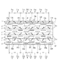
図1は本発明の第1の実施形態に係る導波管スロットアンテナの斜視図であり、図2は導波管スロットアンテナの正面図である。図1において、この導波管スロットアンテナは、例えば航空機の翼部分に取り付けられるものであり、複数(本実施形態では4つ)の第1導波管1と複数(本実施形態では4つ)の第2導波管2とを管軸に直交する方向(図1の上下方向)に交互に積み重ねて一体化したものである。この第1導波管1及び第2導波管2は、設計周波数を中心とする所定の周波数帯域(本実施形態では9.3〜9.8GHz)において複数の周波数を使用するものである。
[First Embodiment]
Hereinafter, embodiments of the present invention will be described with reference to the drawings.
FIG. 1 is a perspective view of a waveguide slot antenna according to the first embodiment of the present invention, and FIG. 2 is a front view of the waveguide slot antenna. In FIG. 1, this waveguide slot antenna is attached to, for example, a wing portion of an aircraft, and includes a plurality (four in this embodiment) of
第1導波管1は、断面矩形状に形成されており、水平偏波を放射する複数の第1スロット素子(傾斜スロット素子)12a〜12hを有している。各第1スロット素子12a〜12hは、第1導波管1の狭壁面11aに、管軸に対して傾斜する方向に延びて形成されている。
The
第2導波管2は、断面コ字状に形成されたリッジ導波管からなり、垂直偏波を放射する複数の第2スロット素子(水平スロット素子)22a〜22hを有している。各第2スロット素子22a〜22hは、第2導波管2の広壁面21aに、管軸に平行な方向に延びて形成されている。
The
図1において、第2導波管2を挟んで隣り合う2つの第1導波管1の素子間隔L1、及び第1導波管1を挟んで隣り合う2つの第2導波管2の素子間隔L2は、それぞれ0.8λ0以下の長さに設定されている。ここで、λ0は使用周波数の自由空間波長である。
In FIG. 1, the element interval L1 between two
具体的には、第1導波管1の積み重ね方向に対向する広壁面間の幅D1は5mmであって、標準の導波管の当該幅(10mm)よりも短く設定されている。また、第2導波管2の積み重ね方向に対向する狭壁面間の幅D2は15mm、第1導波管1及び第2導波管2の板厚tは1mm、自由空間波長λ0は約31mmにそれぞれ設定されている。これにより、前記素子間隔L1及びL2は22mm(≒0.7λ0)に設定されている。
Specifically, the width D1 between the wide wall surfaces facing the stacking direction of the
図2において、第1導波管1は、管軸方向の中央部に、電力が供給される第1給電点13を有している。この第1給電点13を挟んで管軸方向に隣り合う2つの第1スロット素子12d,12eは、第1給電点13からそれぞれ同一長さ離れた位置で同じ方向に傾斜している。具体的には、各第1スロット素子12d,12eは、第1給電点13からそれぞれλg/4離れた位置を中心として、第1導波管1の管軸X1に対して所定角度θ(本実施形態では50度)だけ傾斜している。ここで、λgは使用周波数の管内波長である。
In FIG. 2, the
前記第1スロット素子12dよりも管軸方向一方側(図2の左側)の第1スロット素子12a〜12cは、管軸方向に所定長さ(λg/2)毎に、交互に逆方向に傾斜角度θだけ傾斜するように配置されている。前記第1スロット素子12eよりも管軸方向他方側(図2の右側)の第1スロット素子12f〜12hは、管軸方向一方側と同様に、管軸方向に所定長さ(λg/2)毎に、交互に逆方向に傾斜角度θだけ傾斜するように配置されている。
The
第2導波管2を挟んで隣り合う2つの第1導波管1は、各第1給電点13において相互に逆位相で給電されている。そして、これら2つの第1導波管1のうち、一方の第1導波管1の第1スロット素子12d,12eと、他方の第1導波管1の第1スロット素子12d,12eとは、それぞれ相互に逆方向に傾斜している。これに伴って、前記一方の第1導波管1の第1スロット素子12a〜12c,12f〜12hと、前記他方の第1導波管1の第1スロット素子12a〜12c,12f〜12hとは、それぞれ相互に逆方向に傾斜している。
Two
第2導波管2は、管軸方向の中央部に、電力が供給される第2給電点23を有している。この第2給電点23を挟んで管軸方向に隣り合う2つの第2スロット素子22d,22eは、第2給電点23からそれぞれ同一長さ離れた位置において、第2導波管2の管軸X2に対して相互に逆方向にオフセットした状態で配置されている。具体的には、各第2スロット素子22d,22eは、第2給電点23からそれぞれλg/4離れた位置を中心として配置され、かつ第2給電点23を中心として相互に点対称に配置されている。
The
前記第2スロット素子22dよりも管軸方向一方側(図2の左側)の第2スロット素子22a〜22cは、管軸方向に所定長さ(λg/2)毎に、交互に逆方向にオフセットした状態で配置されている。前記第2スロット素子22eよりも管軸方向他方側(図2の右側)の第2スロット素子22f〜22hは、管軸方向一方側と同様に、管軸方向に所定長さ(λg/2)毎に、交互に逆方向にオフセットした状態で配置されている。
The
第1導波管1を挟んで隣り合う2つの第2導波管2は、各第2給電点23において相互に同位相で給電されている。そして、これら2つの第2導波管2のうち、一方の第2導波管2の第2スロット素子22d,22eと、他方の第2導波管2の第2スロット素子22d,22eとは、それぞれ同じ方向にオフセットした状態で配置されている。これに伴って、前記一方の第2導波管2の第2スロット素子22a〜22c,22f〜22hと、前記他方の第2導波管2の第2スロット素子22a〜22c,22f〜22hとは、それぞれ同じ方向にオフセットした状態で配置されている。
Two
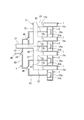
図3は、導波管スロットアンテナの側面図である。図3において、導波管スロットアンテナは、各第1導波管1に電力を供給するための第1給電路3と、各第2導波管2に電力を供給するための第2給電路4とをさらに備えている。
第1給電路3は、例えば導波管によって形成されており、導波管スロットアンテナの裏側において管軸方向中央部に配置されている(図1参照)。この第1給電路3は、給電主路31と、この給電主路31から分岐された2つの第1分岐路32と、この各第1分岐路32からそれぞれ分岐された4つの第2分岐路33とによって構成されている。
FIG. 3 is a side view of the waveguide slot antenna. In FIG. 3, the waveguide slot antenna includes a
The
給電主路31は、第1導波管1の積み重ね方向の略中央部に配置されており、その一端は図示しない給電部に接続され、他端は前記積み重ね方向と直交する方向(図3の左右方向)に延びている。給電主路31の他端には、前記積み重ね方向に延びる各第1分岐路32の一端がそれぞれ接続されている。各第1分岐路32には、それぞれ2つの第2分岐路33の一端が接続されている。各第2分岐路33は、給電主路31の管軸に平行な方向に延びており、その他端は第1導波管1の狭壁面11bに接続されている。これにより、前記給電部から給電主路31、第1分岐路32及び第2分岐路33を経て、第1導波管1の管軸方向中央部に電力が給電される。
The power feed
第2給電路4は、例えば同軸ケーブルによって形成されており、導波管スロットアンテナの裏側において管軸方向中央部に配置されている。この第2給電路4は、給電主路41と、この給電主路41から分岐された2つの第1分岐路42と、この各第1分岐路42からそれぞれ分岐された4つの第2分岐路43とによって構成されている。
The
給電主路41は、第2導波管2の積み重ね方向の略中央部に配置されており、その一端は図示しない給電部に接続され、他端は前記積み重ね方向と直交する方向(図3の左右方向)に延びている。給電主路41の他端には、分岐接続部44を介して2つの第1分岐路42の一端が接続されている。各第1分岐路42は、前記積み重ね方向と直交する方向(図3の左右方向)に延びた後、第2導波管2側に向けて直角に屈曲している。
The power feed
第1分岐路42の他端には、分岐接続部45を介してそれぞれ2つの第2分岐路43の一端が接続されている。各第2分岐路43は、前記積み重ね方向に少し延びた後、給電主路41の管軸に平行な方向に延びており、その他端は第2導波管2の凹底面21bに接続されている。これにより、前記給電部から給電主路41、第1分岐路42及び第2分岐路43を経て、第2導波管2の管軸方向中央部に電力が給電される。
One end of each of the two
以上、本発明の実施形態に係る導波管スロットアンテナによれば、第1導波管1と共に交互に積み重ねる第2導波管2を断面コ字状のリッジ導波管で形成することにより、同一の管内波長をもつ断面縦長矩形状の導波管に比べ、第2導波管を小さくすることができるため、その積み重ね方向の素子間隔L1,L2が大きくなるのを抑制することができる。したがって、水平偏波を放射する第1導波管1と垂直偏波を放射する第2導波管2とを一体化しても、グレーティングローブが発生するのを抑制することができる。
As described above, according to the waveguide slot antenna according to the embodiment of the present invention, the
また、第2導波管2を挟んで隣り合う2つの第1導波管1の素子間隔L1、及び第1導波管1を挟んで隣り合う2つの第2導波管2の素子間隔L2が0.8λ0以下の長さに設定することにより、前記各素子間隔L1,L2を適切な長さにすることができるため、グレーティングローブが発生するのを効果的に抑制することができる。
Further, the element interval L1 between two
また、第1導波管1において、第1給電点13を挟んで管軸方向に隣り合う2つの第1スロット素子12d,12eが、当該第1給電点13からそれぞれ同一長さ離れた位置で同じ方向に傾斜しているため、前記隣り合う2つの第1スロット素子12d,12eには、それぞれ同じ方向に電界が生じる。これにより、各第1スロット素子12d,12eからそれぞれ放射される電波の重ね合わせにより、主ビーム方向への放射強度を高めることができる。
In the
また、第2導波管2を挟んで隣り合うとともに、相互に逆位相で給電される2つの第1導波管1のうち、一方の第1導波管1の前記隣り合う第1スロット素子12d,12eと、他方の第1導波管1の前記隣り合う第1スロット素子12d,12eとが、相互に逆方向に傾斜しているため、前記各第1導波管1のそれぞれにおける前記隣り合う第1スロット素子12d,12eには、すべて同じ方向に電界が生じる。これにより、各第1導波管1の前記第1スロット素子12d,12eからそれぞれ放射される電波の重ね合わせにより、主ビーム方向への放射強度を高めることができる。
The adjacent first slot elements of one of the
また、第1導波管1を挟んで隣り合うとともに、相互に同位相で給電される2つの第2導波管2のうち、一方の第2導波管2の前記隣り合う第2スロット素子22d,22eと、他方の第2導波管2の前記隣り合う第2スロット素子22d,22eとが、同じ方向にオフセットした状態で配置されているため、前記各第2導波管2のそれぞれにおける前記隣り合う第2スロット素子22d,22eには、すべて同じ方向に電界が生じる。これにより、各第2導波管2の前記第2スロット素子22d,22eからそれぞれ放射される電波の重ね合わせにより、主ビーム方向への放射強度を高めることができる。
The adjacent second slot elements of one
また、第1導波管1及び第2導波管2は、設計周波数を中心とする所定の周波数帯域において複数の周波数を使用することができる。
Further, the
〔第2の実施形態〕
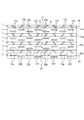
図4は本発明の第2の実施形態に係る導波管スロットアンテナの正面図である。本実施形態と第1の実施形態とが主に相違する点は、隣り合う2つの第1導波管における各第1スロット素子の配置が異なる点、及び隣り合う2つの第2導波管における各第2スロット素子の配置が異なる点である。
[Second Embodiment]
FIG. 4 is a front view of a waveguide slot antenna according to the second embodiment of the present invention. The main difference between this embodiment and the first embodiment is that the arrangement of the first slot elements in the two adjacent first waveguides is different, and in the two adjacent second waveguides. The arrangement of the second slot elements is different.
本実施形態において、第2導波管2を挟んで隣り合う2つの第1導波管1は、各第1給電点13において相互に同位相で給電されている。そして、これら2つの第1導波管1のうち、一方の第1導波管1の第1スロット素子12d,12eと、他方の第1導波管1の第1スロット素子12d,12eとは、それぞれ同じ方向に傾斜している。これに伴って、前記一方の第1導波管1の第1スロット素子12a〜12c,12f〜12hと、前記他方の第1導波管1の第1スロット素子12a〜12c,12f〜12hとは、それぞれ同じ方向に傾斜している。
In the present embodiment, two
第1導波管1を挟んで隣り合う2つの第2導波管2は、各第2給電点23において相互に逆位相で給電されている。そして、これら2つの第2導波管2のうち、一方の第2導波管2の第2スロット素子22d,22eと、他方の第2導波管2の第2スロット素子22d,22eとは、それぞれ相互に逆方向にオフセットした状態で配置されている。これに伴って、前記一方の第2導波管2の第2スロット素子22a〜22c,22f〜22hと、前記他方の第2導波管2の第2スロット素子22a〜22c,22f〜22hとは、それぞれ相互に逆方向にオフセットした状態で配置されている。
Two
以上、本実施形態に係る導波管スロットアンテナにおいては、相互に同位相で給電される2つの第1導波管1のうち、一方の第1導波管1の前記隣り合う第1スロット素子12d,12eと、他方の第1導波管1の前記隣り合う第1スロット素子12d,12eとが、同じ方向に傾斜しているため、前記各第1導波管1のそれぞれにおける前記隣り合う第1スロット素子12d,12eには、すべて同じ方向に電界が生じる。これにより、各第1導波管1の前記第1スロット素子12d,12eからそれぞれ放射される電波の重ね合わせにより、主ビーム方向への放射強度を高めることができる。
As described above, in the waveguide slot antenna according to the present embodiment, the adjacent first slot elements of one of the
また、第1導波管1を挟んで隣り合うとともに、相互に逆位相で給電される2つの第2導波管2のうち、一方の第2導波管2の前記隣り合う第2スロット素子22d,22eと、他方の第2導波管2の前記隣り合う第2スロット素子22d,22eとが、相互に逆方向にオフセットした状態で配置されているため、前記各第2導波管2のそれぞれにおける前記隣り合う第2スロット素子22d,22eには、すべて同じ方向に電界が生じる。これにより、各第2導波管2の前記第2スロット素子22d,22eからそれぞれ放射される電波の重ね合わせにより、主ビーム方向への放射強度を高めることができる。
The adjacent second slot elements of one
〔第3の実施形態〕
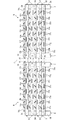
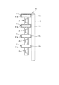
図5は本発明の第3の実施形態に係る導波管スロットアンテナの正面図である。図5において、本実施形態の導波管スロットアンテナは、第1導波管1及び第2導波管2を交互に積み重ねた1列の導波管列5が、その積み重ね方向に延びる仮想線Cを挟んで相互に線対称となるように2列配置されている。
[Third Embodiment]
FIG. 5 is a front view of a waveguide slot antenna according to the third embodiment of the present invention. In FIG. 5, the waveguide slot antenna of the present embodiment has a virtual line in which one row of
第1導波管1の狭壁面11aには、第1スロット素子12a〜12hが、管軸方向に所定長さ(λg/2)毎に、交互に逆方向に傾斜するように配置されている。そして、第2導波管2を挟んで隣り合う2つの第1導波管1のうち、一方の第1導波管1の第1スロット素子12a〜12hと、他方の第1導波管1の第1スロット素子12a〜12hとは、それぞれ同じ方向に傾斜している。
On the
第2導波管2の広壁面21aには、第2スロット素子22a〜22hが、管軸方向に所定長さ(λg/2)毎に、交互に逆方向にオフセットした状態で配置されている。そして、第1導波管1を挟んで隣り合う2つの第2導波管2のうち、一方の第2導波管2の第2スロット素子22a〜22hと、他方の第2導波管2の第2スロット素子22a〜22hとは、それぞれ同じ方向にオフセットした状態で配置されている。
On the
各導波管列5は、第1導波管1に電力を供給するための第1給電路7と、各第2導波管2に電力を供給するための第2給電路8とを備えている。
第1給電路7及び第2給電路8は、例えば導波管によって形成されており、導波管列5の裏側の管軸方向の一端部に第1給電路7が、管軸方向の他端部に第2給電路8がそれぞれ配置されている。
Each
The
図6は図5の左側の導波管列5の右側面図である。図6において、第1給電路7は、第1導波管1の積み重ね方向に延びており、その一端は図示しない給電部に接続されている。第1給電路7は、その長手方向の4箇所において各第1導波管1の狭壁面11bに接続されている。これにより、前記給電部から第1給電路7を経て、第1導波管1の管軸方向端部に電力が給電される。
FIG. 6 is a right side view of the
図7は図5の左側の導波管列5の左側面図である。図7において、第2給電路8は、給電主路81と、この給電主路81から分岐された4つの分岐路82とによって構成されている。給電主路81は、第2導波管2の積み重ね方向に延びており、その一端は図示しない給電部に接続されている。給電主路81には、各分岐路82の一端が接続されている。各分岐路82の他端は、給電主路81に対して垂直な方向に延びて、第2導波管2の凹底面21bに接続されている。これにより、前記給電部から給電主路81及び分岐路82を経て、第2導波管2の管軸方向端部に電力が給電される。
FIG. 7 is a left side view of the
図5において、第1導波管1は、管軸方向の一端部に第1給電スロット素子14を有している。この第1給電スロット14は、第1導波管1の狭壁面11bにおいて第1給電路7との接続箇所に形成されている。第2導波管2を挟んで隣り合う2つの第1導波管1の各第1給電スロット素子14には、相互に逆位相で給電されるようになっている。このため、前記2つの第1導波管1の各第1給電スロット素子14は、第1導波管1の管軸方向の他端側に向けて同位相で給電するように、管軸X1に対して相互に逆方向に傾斜している。
In FIG. 5, the
各第2導波管2は、管軸方向の他端部に第2給電スロット素子24を有している。この第2給電スロット24は、第2導波管2の凹底面21bにおいて第2給電路8の分岐路82との接続箇所に形成されている。第1導波管1を挟んで隣り合う2つの第2導波管2の各第2給電スロット素子24には、相互に逆位相で給電されるようになっている。このため、前記2つの第2導波管2の各第2給電スロット素子24は、第2導波管2の管軸方向の一端側に向けて同位相で給電するように、管軸X2に対して相互に逆方向に傾斜している。
Each
以上、本実施形態に係る導波管スロットアンテナにおいては、管軸方向両端部からそれぞれ給電される第1導波管1及び第2導波管2を交互に積み重ねた1列の導波管列5を2列配置するとともに、この2列の導波管列を線対称に配置することで、周波数の違い(管内波長の違い)による電界放射のピーク方向のずれが生じることなく、使用周波数におけるすべての周波数で電界放射のピーク方向を一定にすることができる。
As described above, in the waveguide slot antenna according to the present embodiment, one row of waveguide rows in which the
[その他の変形例]
今回開示された実施の形態はすべての点で例示であって制限的なものでないと考えられるべきである。本発明の範囲は、上記した意味ではなく、特許請求の範囲によって示され、特許請求の範囲と均等の意味、及び範囲内でのすべての変更が含まれることが意図される。
[Other variations]
The embodiment disclosed this time must be considered as illustrative in all points and not restrictive. The scope of the present invention is defined by the terms of the claims, rather than the meanings described above, and is intended to include any modifications within the scope and meaning equivalent to the terms of the claims.
例えば、上記各実施形態における第1導波管1及び第2導波管2の積み重ね個数や、第1スロット素子12a〜12h及び第2スロット素子22a〜22hの個数は、任意に変更可能である。
また、上記第1及び第2の実施形態において、積み重ね方向に隣り合う第1導波管1の第1給電点13同士及び第2導波管2の第2給電点23同士は、いずれも同位相又は逆位相で給電するようにしてもよい。
For example, the number of stacked
In the first and second embodiments, the first feeding points 13 of the
さらに、第1の実施形態において、第1給電路3及び第2給電路4は、いずれも導波管又は同軸ケーブルにより形成するようにしてもよい。
Furthermore, in 1st Embodiment, you may make it form the 1st electric
1 第1導波管
2 第2導波管
5 導波管列
12a〜12h 第1スロット素子
13 第1給電点
14 第1給電スロット素子
22a〜22h 第2スロット素子
23 第2給電点
24 第2給電スロット素子
DESCRIPTION OF
Claims (6)
垂直偏波を放射する複数の第2スロット素子が管軸に平行な方向に延びて形成された第2導波管と、をそれぞれ複数備え、
前記第1導波管と前記第2導波管とが、管軸に直交する方向に交互に積み重ねられており、
前記第2導波管が、断面コ字状に形成されていることを特徴とする導波管スロットアンテナ。 A first waveguide formed by extending a plurality of first slot elements radiating horizontally polarized waves in a direction inclined with respect to a tube axis;
A plurality of second waveguides formed by extending a plurality of second slot elements that radiate vertically polarized waves in a direction parallel to the tube axis,
The first waveguide and the second waveguide are alternately stacked in a direction perpendicular to the tube axis,
A waveguide slot antenna, wherein the second waveguide has a U-shaped cross section.
前記第1給電点を挟んで管軸方向に隣り合う2つの前記第1スロット素子が、当該第1給電点からそれぞれ同一長さ離れた位置で同じ方向に傾斜している請求項1又は2に記載の導波管スロットアンテナ。 The first waveguide has a first feeding point at a central portion in the tube axis direction,
The two first slot elements adjacent to each other in the tube axis direction across the first feeding point are inclined in the same direction at positions away from the first feeding point by the same length. A waveguide slot antenna as described.
前記2つの第1導波管のうち、一方の第1導波管の前記隣り合う2つの第1スロット素子と、他方の第1導波管の前記隣り合う2つの第1スロット素子とが、同じ方向に傾斜している請求項3に記載の導波管スロットアンテナ。 Two first waveguides adjacent to each other across the second waveguide are fed in phase with each other at the first feeding point,
Of the two first waveguides, the two adjacent first slot elements of one first waveguide and the two adjacent first slot elements of the other first waveguide are: The waveguide slot antenna according to claim 3, wherein the waveguide slot antenna is inclined in the same direction.
前記2つの第1導波管のうち、一方の第1導波管の前記隣り合う2つの第1スロット素子と、他方の第1導波管の前記隣り合う2つの第1スロット素子とが、相互に逆方向に傾斜している請求項3に記載の導波管スロットアンテナ。 Two first waveguides adjacent to each other across the second waveguide are fed in opposite phases at the first feeding point,
Of the two first waveguides, the two adjacent first slot elements of one first waveguide and the two adjacent first slot elements of the other first waveguide are: The waveguide slot antenna according to claim 3, wherein the waveguide slot antennas are inclined in directions opposite to each other.
前記第2導波管は、管軸方向の他端部に第2給電スロット素子を有し、
前記第1導波管及び第2導波管を交互に積み重ねた1列の導波管列が、その積み重ね方向に延びる線を挟んで相互に線対称となるように2列配置されている請求項1又は2に記載の導波管スロットアンテナ。 The first waveguide has a first feeding slot element at one end in the tube axis direction,
The second waveguide has a second feeding slot element at the other end in the tube axis direction,
Two rows of waveguide rows in which the first waveguide and the second waveguide are alternately stacked are arranged so as to be symmetrical with respect to each other across a line extending in the stacking direction. Item 3. The waveguide slot antenna according to Item 1 or 2.
Priority Applications (1)
| Application Number | Priority Date | Filing Date | Title |
|---|---|---|---|
| JP2011066066A JP2012204975A (en) | 2011-03-24 | 2011-03-24 | Waveguide slot antenna |
Applications Claiming Priority (1)
| Application Number | Priority Date | Filing Date | Title |
|---|---|---|---|
| JP2011066066A JP2012204975A (en) | 2011-03-24 | 2011-03-24 | Waveguide slot antenna |
Publications (1)
| Publication Number | Publication Date |
|---|---|
| JP2012204975A true JP2012204975A (en) | 2012-10-22 |
Family
ID=47185497
Family Applications (1)
| Application Number | Title | Priority Date | Filing Date |
|---|---|---|---|
| JP2011066066A Pending JP2012204975A (en) | 2011-03-24 | 2011-03-24 | Waveguide slot antenna |
Country Status (1)
| Country | Link |
|---|---|
| JP (1) | JP2012204975A (en) |
Cited By (6)
| Publication number | Priority date | Publication date | Assignee | Title |
|---|---|---|---|---|
| JP2014093552A (en) * | 2012-10-31 | 2014-05-19 | Japan Radio Co Ltd | Waveguide slot antenna |
| JP2016213553A (en) * | 2015-04-30 | 2016-12-15 | 住友電気工業株式会社 | Frequency sharing waveguide slot antenna and antenna device |
| CN107634342A (en) * | 2017-08-29 | 2018-01-26 | 大连港森立达木材交易中心有限公司 | A kind of two-way Uniform Irradiation antenna-feedback system |
| WO2018029807A1 (en) * | 2016-08-10 | 2018-02-15 | 三菱電機株式会社 | Array antenna device and method for manufacturing array antenna device |
| US11276940B2 (en) | 2018-05-02 | 2022-03-15 | Mitsubishi Electric Corporation | Waveguide slot array antenna |
| EP4197064A4 (en) * | 2020-10-13 | 2024-02-28 | Univ Oklahoma | X-band dual-polarized slotted waveguide antenna (swga) array unit cell for large e-scanning radar systems |
Citations (6)
| Publication number | Priority date | Publication date | Assignee | Title |
|---|---|---|---|---|
| JPH01314405A (en) * | 1988-06-14 | 1989-12-19 | Naohisa Goto | Waveguide type plane antenna |
| JPH04213202A (en) * | 1990-01-29 | 1992-08-04 | Alcatel Thomson Espace | Antenna composed of slotted waveguide for space radar in particular |
| JP2005317462A (en) * | 2004-04-30 | 2005-11-10 | Rikogaku Shinkokai | Plasma treatment device and plasma treatment method |
| JP2007221585A (en) * | 2006-02-17 | 2007-08-30 | Furuno Electric Co Ltd | Antenna and manufacturing method thereof |
| JP2008109197A (en) * | 2006-10-23 | 2008-05-08 | Japan Radio Co Ltd | Ridge waveguide center feed slot array antenna |
| JP2011044977A (en) * | 2009-08-24 | 2011-03-03 | Tokyo Institute Of Technology | Array antenna |
-
2011
- 2011-03-24 JP JP2011066066A patent/JP2012204975A/en active Pending
Patent Citations (6)
| Publication number | Priority date | Publication date | Assignee | Title |
|---|---|---|---|---|
| JPH01314405A (en) * | 1988-06-14 | 1989-12-19 | Naohisa Goto | Waveguide type plane antenna |
| JPH04213202A (en) * | 1990-01-29 | 1992-08-04 | Alcatel Thomson Espace | Antenna composed of slotted waveguide for space radar in particular |
| JP2005317462A (en) * | 2004-04-30 | 2005-11-10 | Rikogaku Shinkokai | Plasma treatment device and plasma treatment method |
| JP2007221585A (en) * | 2006-02-17 | 2007-08-30 | Furuno Electric Co Ltd | Antenna and manufacturing method thereof |
| JP2008109197A (en) * | 2006-10-23 | 2008-05-08 | Japan Radio Co Ltd | Ridge waveguide center feed slot array antenna |
| JP2011044977A (en) * | 2009-08-24 | 2011-03-03 | Tokyo Institute Of Technology | Array antenna |
Cited By (8)
| Publication number | Priority date | Publication date | Assignee | Title |
|---|---|---|---|---|
| JP2014093552A (en) * | 2012-10-31 | 2014-05-19 | Japan Radio Co Ltd | Waveguide slot antenna |
| JP2016213553A (en) * | 2015-04-30 | 2016-12-15 | 住友電気工業株式会社 | Frequency sharing waveguide slot antenna and antenna device |
| WO2018029807A1 (en) * | 2016-08-10 | 2018-02-15 | 三菱電機株式会社 | Array antenna device and method for manufacturing array antenna device |
| US11605903B2 (en) | 2016-08-10 | 2023-03-14 | Mitsubishi Electric Corporation | Array antenna apparatus and method for manufacturing array antenna apparatus |
| CN107634342A (en) * | 2017-08-29 | 2018-01-26 | 大连港森立达木材交易中心有限公司 | A kind of two-way Uniform Irradiation antenna-feedback system |
| CN107634342B (en) * | 2017-08-29 | 2020-06-05 | 大连港森立达木材交易中心有限公司 | Bidirectional uniform irradiation antenna feeder system |
| US11276940B2 (en) | 2018-05-02 | 2022-03-15 | Mitsubishi Electric Corporation | Waveguide slot array antenna |
| EP4197064A4 (en) * | 2020-10-13 | 2024-02-28 | Univ Oklahoma | X-band dual-polarized slotted waveguide antenna (swga) array unit cell for large e-scanning radar systems |
Similar Documents
| Publication | Publication Date | Title |
|---|---|---|
| JP4602276B2 (en) | Waveguide slot array antenna device | |
| US8134514B2 (en) | Coaxial line slot array antenna and method for manufacturing the same | |
| JP2012204975A (en) | Waveguide slot antenna | |
| JP5558943B2 (en) | Slot array antenna and radar device | |
| CA2823340C (en) | Waveguide-configuration adapters | |
| JP4531033B2 (en) | Ridge waveguide center-fed slot array antenna | |
| JP5639015B2 (en) | Antenna device, radar device, and dielectric member arrangement method | |
| US8599063B2 (en) | Antenna device and radar apparatus | |
| JP5437740B2 (en) | Array antenna | |
| JP6530814B2 (en) | Array antenna | |
| JP2017225023A (en) | Array antenna device | |
| JP5495955B2 (en) | Waveguide slot array antenna | |
| JP6569435B2 (en) | Array antenna | |
| JP4709601B2 (en) | Waveguide slot array antenna | |
| JP2000236213A (en) | Waveguide slot array antenna | |
| JP2010177983A (en) | Patch array antenna | |
| JP5616167B2 (en) | Traveling wave excitation antenna | |
| JP6611238B2 (en) | Waveguide / transmission line converter, array antenna, and planar antenna | |
| JP3895285B2 (en) | Waveguide array antenna | |
| JP3848944B2 (en) | Waveguide slot array antenna | |
| JP5300626B2 (en) | Antenna device | |
| JP7115780B1 (en) | array antenna | |
| JPH11274848A (en) | Waveguide slot array antenna | |
| JP2008172703A (en) | Antenna equipment | |
| JP2022006587A (en) | Array antenna |
Legal Events
| Date | Code | Title | Description |
|---|---|---|---|
| A621 | Written request for application examination |
Free format text: JAPANESE INTERMEDIATE CODE: A621 Effective date: 20131129 |
|
| A977 | Report on retrieval |
Free format text: JAPANESE INTERMEDIATE CODE: A971007 Effective date: 20140526 |
|
| A131 | Notification of reasons for refusal |
Free format text: JAPANESE INTERMEDIATE CODE: A131 Effective date: 20140729 |
|
| A521 | Written amendment |
Free format text: JAPANESE INTERMEDIATE CODE: A523 Effective date: 20140918 |
|
| A131 | Notification of reasons for refusal |
Free format text: JAPANESE INTERMEDIATE CODE: A131 Effective date: 20141125 |
|
| A521 | Written amendment |
Free format text: JAPANESE INTERMEDIATE CODE: A523 Effective date: 20150114 |
|
| A02 | Decision of refusal |
Free format text: JAPANESE INTERMEDIATE CODE: A02 Effective date: 20150630 |