EP4266487B1 - Communication device and associated method - Google Patents
Communication device and associated method Download PDFInfo
- Publication number
- EP4266487B1 EP4266487B1 EP22169303.9A EP22169303A EP4266487B1 EP 4266487 B1 EP4266487 B1 EP 4266487B1 EP 22169303 A EP22169303 A EP 22169303A EP 4266487 B1 EP4266487 B1 EP 4266487B1
- Authority
- EP
- European Patent Office
- Prior art keywords
- window
- metallic
- transparent
- antenna system
- communication system
- Prior art date
- Legal status (The legal status is an assumption and is not a legal conclusion. Google has not performed a legal analysis and makes no representation as to the accuracy of the status listed.)
- Active
Links
Images


Classifications
-
- H—ELECTRICITY
- H01—ELECTRIC ELEMENTS
- H01Q—ANTENNAS, i.e. RADIO AERIALS
- H01Q1/00—Details of, or arrangements associated with, antennas
- H01Q1/12—Supports; Mounting means
- H01Q1/1271—Supports; Mounting means for mounting on windscreens
-
- H—ELECTRICITY
- H01—ELECTRIC ELEMENTS
- H01Q—ANTENNAS, i.e. RADIO AERIALS
- H01Q1/00—Details of, or arrangements associated with, antennas
- H01Q1/12—Supports; Mounting means
- H01Q1/1207—Supports; Mounting means for fastening a rigid aerial element
-
- H—ELECTRICITY
- H01—ELECTRIC ELEMENTS
- H01Q—ANTENNAS, i.e. RADIO AERIALS
- H01Q5/00—Arrangements for simultaneous operation of antennas on two or more different wavebands, e.g. dual-band or multi-band arrangements
- H01Q5/50—Feeding or matching arrangements for broad-band or multi-band operation
Definitions
- the present invention relates to a communication device in general and, more specifically, to a communication device comprising an enhanced performance antenna system with a transparent open container to optimize the transmission and / or the reception of the radio-frequency signals in wireless communications through a window.
- the present invention also relates to associated methods and uses.
- the invention concerns multiple domains where a communication device is used to optimize the transmission and / or the reception of an antenna system through a window.
- the antenna system can be designed in such a way that it provides coverage for both indoors and outdoors.
- the antenna system is a transparent antenna in order to keep the aesthetics of the building as much as possible.
- the antenna itself not only radiates within its main beam, but also emits an amount of energy in all directions including backwards.
- the document WO2013092821 describes an optically transparent antenna and a optically transparent container with a back side and lateral sides.
- the document WO2019107514 describes an antenna system having a conductive film on the back side.
- An object of one embodiment of the present invention is to provide a communication system with an antenna system installed in front of and radiating efficiently through a window while the total backward electromagnetic field emission due to the back radiation of the antenna system and the reflection of the radiated energy from the interface of the air and the glazing is limited.
- the present invention relates, in a first aspect, to a communication system comprising a window, a transparent open container.
- the transparent open container comprises a back side and at least two opposite lateral sides. Each of the back side and the lateral sides comprise a same metallic-based material.
- the communication system comprises a transparent antenna system radiating at a defined range of wavelengths and an installation interface panel.
- the solution as defined in the first aspect of the present invention is based on that the communication system further comprises a fixing means configured to attach the antenna system and the installation interface panel inside the transparent open container and configured to attach the antenna system and the interface layer in front of the window.
- the solution as defined in the first aspect of the present invention is also based on that the antenna system is placed between the back side and the installation interface panel at a defined distance, Daw wherein Daw >0, from the window.
- the solution as defined in the first aspect of the present invention is also based on that the installation interface panel is placed a defined distance, Diw wherein Diw ⁇ 0, from the window, wherein the metallic-based material of the back side and the lateral sides is a continuous metallic-based sheet, preferably a single continuous metallic-based sheet, wherein the metallic-based sheet is a metallic meshed structure, and wherein the metallic meshed structure is a woven metallic mesh
- the present invention allows the antenna system to radiate higher effective isotropic radiated power towards the desired direction through the window and / or to radiate lower effective isotropic radiated power towards the undesired directions behind the transparent open container manufactured by the first aspect of the present invention.
- the present invention relates, in a second aspect, to the use of a communication system in compliance with radiofrequency electromagnetic field exposure standards according to the first aspect of the invention to radiate through the window comprising an interior surface and an exterior surface; the antenna system being attached in front of on the interior surface.
- the assembly of the antenna system, the installation interface panel and the transparent open container of the communication system of the first aspect of the invention helps to reduce the energy emitted at a determined distance from the antenna system behind the transparent open container.
- the present invention solves the need to find new location to place an antenna system for enhanced network densification while allowing seamless and aesthetic integration into urban environments while reducing health risk by reducing the unwanted electromagnetic field exposure of the communication system.
- first, second and the like in the description and in the claims are used for distinguishing between similar elements and not necessarily for describing a sequence, either temporally, spatially, in ranking or in any other manner. It is to be understood that the terms so used are interchangeable under appropriate circumstances and that the embodiments of the invention described herein are capable of operation in other sequences than described or illustrated herein.
- a constituent element e.g., a first constituent element
- another constituent element e.g., a second constituent element
- the constituent element may be directly connected to the another constituent element or may be connected to the another constituent element through another constituent element (e.g., a third constituent element).
- the back side and the lateral sides of the transparent open container comprise a metallic-based material.
- the metallic-based material is a continuous metallic-based sheet.
- continuous means that the metallic-based is composed of unseparated parts.
- the continuous metallic-based sheet is a single continuous metallic-based sheet meaning that is the single sheet is used for the back side and for lateral sides.
- the continuous metallic-based sheet is preferably a transparent continuous metallic-based sheet.
- the continuous metallic-based sheet is a metallic meshed structure.
- the metallic meshed structure is preferably a metallic mesh in form of a grid.
- the grid can have any shape such as rectangular, hex, squared, circular, ⁇ in order to shield against EM fields at a given range of wavelengths.
- the metallic meshed structure can be advantageously a transparent metallic meshed structure made of transparent semiconductor materials such as Indium Thin Oxide.
- the metallic meshed structure is not transparent.
- a coating can be applied on top and/or the bottom of the metallic meshed structure, preferably a blackened coating to protect the metallic material while reducing the diffusion.
- the conductive metallic meshed structure can be obtained from a metallic foil machined in such a way it becomes optically transparent while keeping an electrical opacity. This machining is called “meshing" and is described as follows.
- dimensioning of the meshing is characterized by its pitch (or its periodicity), by the width and the thickness of the conductive tracks (or by the opening made in the pitch).
- the thickness and the width of the meshing is equal to or higher than three times the skin depth of the metallic material at the given range of wavelengths, preferably thickness and the width of the meshing is equal to or higher than four times the skin depth of the metallic material at the given range of wavelengths, and more preferably thickness and the width of the meshing is equal to or higher than five times the skin depth of the metallic material at the given range of wavelengths.
- the optical transparency of the metallic meshed structure, TLm is defined, in a first approximation, as the ratio of opened surfaces over total surface.
- the ratio can be adapted to obtain the desired optical transparency keeping an electrical opacity.
- the unit cell of the grid should much lower than the operating wavelength of an enclosed antenna system, given by the operating frequency f, in GigaHertz (GHz).
- the meshed structure is a woven metallic mesh and more preferably a fine woven metallic mesh to have this optical transparency while keeping the electrical opacity.
- the meshed structure is a metal, such as copper, Aluminium, silver, stainless steel.
- the meshed structure can be disposed on a plastic film, preferably with a thickness of 25 to 200 ⁇ m.
- the plastic film is preferably a polymer film and a transparent polymer film.
- transparent polymer film can be polyvinyl butyral (PVB), ethylene-vinyl acetate (EVA), polymethyl methacrylate (PMMA), a polycarbonate (PC), a polystyrene (PS), a polyvinyl chloride (PVC), a polyamide (PA), a polyetherimide (PEI), a polyethylene terephthalate (PET), a polyurethane, an acrylonitrile butadiene styrene copolymer (ABS), a styrene acrylonitrile copolymer (SAN), a styrene methyl methacrylate copolymer (SMMA) and any mixtures of these, a crosslinked resin, an ionoplast, an ionomer, a cyclo-olefin polymer (COP), cyclo-Olefin copolymer (COC) or an Optical Clear Adhesive (OCA).
- PVB polyvinyl
- Crosslinked or cured resins are known to the skilled person and are three dimensional polymer networks obtained by the crosslinking/curing of low molecular weight species either by reaction with a curing agent also known as crosslinker or upon exposure to heat, UV radiations (UV) or electron beam (EB).
- Non exhaustive examples of crosslinked resins are epoxy resins, polyurethane resins, UV or EB curable resins.
- the precursors of the crosslinked resin may be transparent or not provided that the crosslinked resin is transparent.
- Antenna system has typically a weight of about 1 kg to 10 kg and in some embodiments about 2 kg to 3 kg.
- the parallelepiped has typically a width and / or a length comprised between 20 mm to 600 mm for example a rectangular shape of 210 mm x 250 mm, a rectangular shape of 150 mm x 160 mm or rectangular shape of 255 mm x 500 mm depending on the operating frequencies, the number of antenna arrangements, the number of elements comprised in the antenna arrangement and / or the transparency design.
- the transparent antenna system can comprises at least one antenna unit.
- An antenna unit works for Wi-Fi, 4G and / or 5G, meaning wavelengths with frequencies from 690 MHz to 70 GHz.
- the transparent antenna system can comprises several antenna units working at the same or different range of wavelengths.
- the transparent antenna system can comprise at least one connector protruding from the antenna system to power the antenna unit and transceive the signal.
- a cable is then connected to the at least one connector.
- the number of connectors depends of the number of antenna units and the type of antenna units used.
- the surface of the back side is equal to or greater than the surface defined by the antenna system in the X-Y plane to which it is added the area defined by the height of the at least one connector to minimize back radiation of the at least one connector because the at least one connector might contribute to the radiation of the EM waves.
- the cable can be directly connected to the antenna units without a connector.
- the installation interface panel is placed between the antenna system and the window.
- the installation interface panel permits to cancel out the impact of the window on the antenna system performance and permits to maintain the impedance response of the antenna system as well as the radiation properties of the antenna unit(s) of the antenna system within the specifications.
- the installation interface panel can add more functionalities to the antenna system, such as the beam steering or beam shaping.
- the installation interface panel can comprise at least a transparent dielectric panel such as glass and / or plastic.
- at least a conductive pattern can be deposited on at least one of dielectric panels.
- the communication system further comprises a fixing means.
- the fixing means is configured to attach the antenna system and the installation interface panel inside the transparent open container and configured to attach the antenna system and the interface layer in front of the window, meaning that the transparent open container is at least partially surrounding the antenna system and the installation interface panel.
- the antenna system is placed between the back side and the installation interface panel at a defined distance, Daw, a strictly positive integer (Daw > 0), from the window.
- the installation interface panel is placed a defined distance, Diw, a positive integer (Diw ⁇ 0), from the window.
- the antenna system can be in front of the exterior surface of the window to radiate through the window to the inside of the object.
- the antenna system can be in front of the interior surface of the window to radiate through the window to the outside of the object.
- the antenna system and the transparent open container are installed on the interior side of the window, meaning inside the building and the antenna radiates through the window to permit to user outside of the building to obtain an EM signal while restricting the radiation of the antenna inside of the object.
- the fixing means can have several shapes depending to the specific application.
- the fixing means can be a single means or a multiple means.
- the fixing means can comprise a hanging means to hang the antenna system in front of the window.
- the hanging means can comprise a cable, a glue, a tape or any other suitable element to hang an antenna system in front of a window.
- cables can have a diameter comprises between 0.5 and 3 mm and more preferably around 2 mm.
- the fixing means can comprise a separating means to separate the antenna system at the defined distance, Daw, from the window and to separate the installation interface panel at the defined distance, Diw, from the window.
- the attaching means can comprise slots in which a portion of lateral sides are fixed and permits to maintain the transparent open container in the correct 3D shape.
- the separating means and the attaching means can be a single mean.
- the present invention relates, in a second aspect, to method of assembling a communication system according the first aspect of the invention.
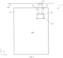
- FIG. 1 illustrates an embodiment in which the antenna system is surrounded by the transparent open container 20.
- the fixing means comprises an hanging means.
- the hanging means comprises two cables 55 to hang the antenna system in front of a window 10 and in front of a surface 101, preferably the interior surface. Cables are attached to the ceiling 110. It is understood that the hanging means can be attached to the frame of the window, to the ceiling or any other place depending on the specific application and location.
- the fixing means comprises an attaching means 50 to attach the antenna system and the installation interface panel inside the transparent open container.
- the attaching means corresponds to four corner elements.
- the antenna system is powered by coaxial cables 35.
- coaxial cable are preferably exiting out of the transparent open container from the top side to the ceiling in a hidden way and connect to a communication (WiFi, 4G and/or 5G) device.
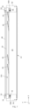
- FIG. 2 illustrates an embodiment the fixing means comprises a separating means 51.
- the separating means comprises elements such as notches to maintain the installation interface layer 40 and the antenna system 30 at a defined distance respectively Diw and Daw from the window 10 to optimize the reception and / or the transmission of the antenna system.
- the defined distance Diw is between 0.5 mm and 10 mm measured from the surface of the window to the first surface of the installation interface layer 40, meaning the nearest surface from the window.
- the defined distance Daw is between 4 mm and 50 mm measured from the surface of the window to the first surface of the antenna system 30, meaning the nearest surface from the window.
- the defined distance Daw is greater than 1/10 of the wavelength, more preferably 1/8 of the wavelength, and 1/4 of the wavelength meaning that preferably the defined distance Daw equals to or is higher than 7 mm for 4G and 5G sub-6 GHz.
- the fixing means comprises an attaching means 50 to attach the antenna system and the installation interface panel inside the transparent open container.
- the attaching means 50 and the separating means 51 can be a single piece or two different pieces.
- the fixing means comprises an hanging means.
- the hanging means can be a cable 55, a glue, a combination of elements to hang the antenna system in front of the window.
- the transparent open container has at least a back side 22 and lateral sides 23, 24.
- the back side comprises a continuous metallic-based sheet 21 and two dielectric panels 221, 222.
- the top lateral side 23 comprises a continuous metallic-based sheet 21 and two dielectric panels 231, 232.
- the continuous metallic-based sheet of the back side and lateral sides is a single continuous metallic-based sheet meaning that it is the same sheet that is sandwiched between interlayers and dielectric panels 221, 222 of the back side and between interlayers and dielectric panels 231, 232 of the lateral sides, the top side 23 as illustrated.
- the main radiation beam of the antenna system 30 passes through the installation interface layer 40 and then through the window 10.
- the transparent open container limits the radiation behind the antenna system.
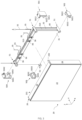
- FIGs. 3 to 7 illustrates an embodiment in which the fixing means comprises a hanging means 55, a separating means 51 and a attaching means 50.
- antenna systems 30 can be made of a single stack of material or double stacks 31, 32 of material.
- the separating means 51 can be separating corner elements to maintain the antenna system 31, 32 at the defined distance Daw from the window.
- tightening means 511, 512, 513, 514 such as rods, designed to tighten said corner elements on the antenna system 31, 32 and the installation interface panel 40 at defined distances Daw, Diw.
- separating corner elements can have any shape such as cylinder shape as illustrated in FIG. 3 .
- attaching means 50 comprises at least two attaching corners elements 501, 502, 503, 504 or any other suitable element to attach an transparent open container around an antenna system.
- said attaching corner elements comprises :
- lateral sides can be pinched, siliconed, glued or any other suitable manner in said slots.
- the attaching means 50 comprises a clipping means 5013, 5023, 5033, 5043 to clip or by any other suitable manner, to the separating means to maintain the transparent open container surrounding the antenna system.
- Such attaching means can be made of plastic, metal or any other suitable material.
- This embodiment is specifically suitable to add a transparent open container to an existing antenna system already placed in front of a window.
- the top side 23 can comprises a cut-off 231 to let feeding coaxial cables 35 passing from the inside of the transparent open container to the outside of the transparent open container.
- the top side 23 can comprise a cut-off 232 to let hanging means passing from the outside of the transparent open container to the inside of the transparent open container.
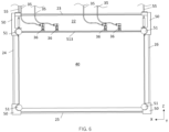
- FIG. 4 illustrates an embodiment in which the transparent open container is surrounding the antenna system.
- the installation interface panel has a surface in the X-Z plane substantially similar to the surface in the X-Z plane of the antenna system 30.
- the antenna system comprises at least one connector 36 to connect feeding coaxial cables 35 to antenna units.
- the surface of the back side 22 is greater than the surface of the antenna 40 to which it is added the area defined by the height of the at least one connector 36.
- the method can comprises a step of manufacturing the transparent open container.
- this step comprises sub-steps of providing a metallic-based material, depositing on at least a surface of the metallic-based material a transparent dielectric panel being fixed by an interlayer; forming a flat assembly; and bending the flat assembly to form a transparent open container.
- the attaching means 50 can comprises opening 503 to let hanging means 55 passing through it.
- the separating means 51 can comprise a glue, a double faced tape, a suction pad or any other means 52 to fix an antenna system on a surface 101 of a window 10.
- dielectric panels of the back side and / or lateral sides are separated from dielectric panels of adjacent side by a non-zero distance to avoid any breakage of said dielectric panels.
- back side and lateral sides are maintained together by a glue, a silicone and / or by the metallic-based material.
- the present invention relates also to a method to add a transparent open container surrounding an antenna system and an installation interface panel to reduce back radiation of the antenna system.
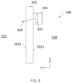
- the invention relates to the use of a communication system 100 to radiate through the window comprising an interior surface and an exterior surface; the antenna system being attached in front of on the interior surface.
- the communication system 100 comprises a window 101, a transparent open container 102, an antenna system 103 radiating 104 at a defined range of wavelengths through the window; the antenna system and the transparent open container been assembled by the method according to the second aspect of the invention.
- the installation interface panel and the transparent open container being attached in front of on the interior surface 1021with the antenna system.
- the antenna system, the installation interface panel and the transparent open container are attached in front of on the exterior surface 1022; the antenna system is radiating through the window to permit to user inside of the building to obtain an EM signal while restricting the radiation of the antenna outside of the object.
- the antenna system, the installation interface panel and the transparent open container are attached directly in front of on the main surface meaning that are substantially against the main surface of the window
- the present invention solves the need to place enhanced antenna system in front of a window.
Landscapes
- Details Of Aerials (AREA)
- Shielding Devices Or Components To Electric Or Magnetic Fields (AREA)
- Transceivers (AREA)
- Support Of Aerials (AREA)
Priority Applications (14)
| Application Number | Priority Date | Filing Date | Title |
|---|---|---|---|
| EP22169303.9A EP4266487B1 (en) | 2022-04-21 | 2022-04-21 | Communication device and associated method |
| ES22169303T ES3014907T3 (en) | 2022-04-21 | 2022-04-21 | Communication device and associated method |
| EP22205419.9A EP4270635A1 (en) | 2022-04-21 | 2022-04-21 | Communication device and associated method |
| PT221693039T PT4266487T (pt) | 2022-04-21 | 2022-04-21 | Dispositivo de comunicação e método associado |
| PCT/EP2023/060204 WO2023203109A1 (en) | 2022-04-21 | 2023-04-19 | Communication device and associated method |
| DK23720860.8T DK4511911T3 (da) | 2022-04-21 | 2023-04-19 | Kommunikationsanordning og tilhørende fremgangsmåde |
| US18/857,685 US20250266603A1 (en) | 2022-04-21 | 2023-04-19 | Communication device and associated method |
| EP23720860.8A EP4511911B1 (en) | 2022-04-21 | 2023-04-19 | Communication device and associated method |
| ES23721840T ES3061631T3 (en) | 2022-04-21 | 2023-04-19 | Communication device and associated method |
| FIEP23720860.8T FI4511911T3 (fi) | 2022-04-21 | 2023-04-19 | Viestintälaite ja siihen liittyvä menetelmä |
| PCT/EP2023/060207 WO2023203110A1 (en) | 2022-04-21 | 2023-04-19 | Communication device and associated method |
| US18/857,707 US20250266604A1 (en) | 2022-04-21 | 2023-04-19 | Communication device and associated method |
| EP23721840.9A EP4511913B1 (en) | 2022-04-21 | 2023-04-19 | Communication device and associated method |
| PL23720860.8T PL4511911T3 (pl) | 2022-04-21 | 2023-04-19 | Urządzenie do prowadzenia łączności i powiązany sposób |
Applications Claiming Priority (1)
| Application Number | Priority Date | Filing Date | Title |
|---|---|---|---|
| EP22169303.9A EP4266487B1 (en) | 2022-04-21 | 2022-04-21 | Communication device and associated method |
Related Child Applications (2)
| Application Number | Title | Priority Date | Filing Date |
|---|---|---|---|
| EP22205419.9A Division-Into EP4270635A1 (en) | 2022-04-21 | 2022-04-21 | Communication device and associated method |
| EP22205419.9A Division EP4270635A1 (en) | 2022-04-21 | 2022-04-21 | Communication device and associated method |
Publications (2)
| Publication Number | Publication Date |
|---|---|
| EP4266487A1 EP4266487A1 (en) | 2023-10-25 |
| EP4266487B1 true EP4266487B1 (en) | 2024-12-18 |
Family
ID=81346086
Family Applications (4)
| Application Number | Title | Priority Date | Filing Date |
|---|---|---|---|
| EP22169303.9A Active EP4266487B1 (en) | 2022-04-21 | 2022-04-21 | Communication device and associated method |
| EP22205419.9A Pending EP4270635A1 (en) | 2022-04-21 | 2022-04-21 | Communication device and associated method |
| EP23720860.8A Active EP4511911B1 (en) | 2022-04-21 | 2023-04-19 | Communication device and associated method |
| EP23721840.9A Active EP4511913B1 (en) | 2022-04-21 | 2023-04-19 | Communication device and associated method |
Family Applications After (3)
| Application Number | Title | Priority Date | Filing Date |
|---|---|---|---|
| EP22205419.9A Pending EP4270635A1 (en) | 2022-04-21 | 2022-04-21 | Communication device and associated method |
| EP23720860.8A Active EP4511911B1 (en) | 2022-04-21 | 2023-04-19 | Communication device and associated method |
| EP23721840.9A Active EP4511913B1 (en) | 2022-04-21 | 2023-04-19 | Communication device and associated method |
Country Status (8)
| Country | Link |
|---|---|
| US (2) | US20250266604A1 (pl) |
| EP (4) | EP4266487B1 (pl) |
| DK (1) | DK4511911T3 (pl) |
| ES (2) | ES3014907T3 (pl) |
| FI (1) | FI4511911T3 (pl) |
| PL (1) | PL4511911T3 (pl) |
| PT (1) | PT4266487T (pl) |
| WO (2) | WO2023203109A1 (pl) |
Families Citing this family (1)
| Publication number | Priority date | Publication date | Assignee | Title |
|---|---|---|---|---|
| ES3014907T3 (en) * | 2022-04-21 | 2025-04-28 | Agc Glass Europe | Communication device and associated method |
Family Cites Families (7)
| Publication number | Priority date | Publication date | Assignee | Title |
|---|---|---|---|---|
| FR2984613B1 (fr) | 2011-12-20 | 2015-05-15 | Bouygues Telecom Sa | Antenne imprimee optiquement transparente et reseau d'antennes optiquement transparentes |
| EP2833474A1 (en) | 2013-07-29 | 2015-02-04 | Bouygues Telecom | Optically transparent panel antenna assembly comprising a shaped reflector |
| US10714809B2 (en) * | 2016-05-10 | 2020-07-14 | AGC Inc. | Antenna for vehicle |
| JP7118068B2 (ja) | 2017-08-02 | 2022-08-15 | Agc株式会社 | ガラス用アンテナユニット、アンテナ付きガラス板、およびガラス用アンテナユニットの製造方法 |
| WO2019107514A1 (ja) | 2017-12-01 | 2019-06-06 | Agc株式会社 | アンテナユニット、およびアンテナ付きガラス板 |
| PL4244933T3 (pl) | 2020-11-16 | 2025-08-11 | Agc Glass Europe | System antenowy |
| ES3014907T3 (en) * | 2022-04-21 | 2025-04-28 | Agc Glass Europe | Communication device and associated method |
-
2022
- 2022-04-21 ES ES22169303T patent/ES3014907T3/es active Active
- 2022-04-21 EP EP22169303.9A patent/EP4266487B1/en active Active
- 2022-04-21 EP EP22205419.9A patent/EP4270635A1/en active Pending
- 2022-04-21 PT PT221693039T patent/PT4266487T/pt unknown
-
2023
- 2023-04-19 FI FIEP23720860.8T patent/FI4511911T3/fi active
- 2023-04-19 US US18/857,707 patent/US20250266604A1/en active Pending
- 2023-04-19 WO PCT/EP2023/060204 patent/WO2023203109A1/en not_active Ceased
- 2023-04-19 ES ES23721840T patent/ES3061631T3/es active Active
- 2023-04-19 EP EP23720860.8A patent/EP4511911B1/en active Active
- 2023-04-19 WO PCT/EP2023/060207 patent/WO2023203110A1/en not_active Ceased
- 2023-04-19 US US18/857,685 patent/US20250266603A1/en active Pending
- 2023-04-19 EP EP23721840.9A patent/EP4511913B1/en active Active
- 2023-04-19 PL PL23720860.8T patent/PL4511911T3/pl unknown
- 2023-04-19 DK DK23720860.8T patent/DK4511911T3/da active
Also Published As
| Publication number | Publication date |
|---|---|
| DK4511911T3 (da) | 2026-03-09 |
| ES3061631T3 (en) | 2026-04-06 |
| FI4511911T3 (fi) | 2026-03-04 |
| US20250266604A1 (en) | 2025-08-21 |
| PL4511911T3 (pl) | 2026-04-20 |
| EP4270635A1 (en) | 2023-11-01 |
| EP4266487A1 (en) | 2023-10-25 |
| WO2023203110A1 (en) | 2023-10-26 |
| EP4511913A1 (en) | 2025-02-26 |
| EP4511911B1 (en) | 2025-12-03 |
| ES3014907T3 (en) | 2025-04-28 |
| US20250266603A1 (en) | 2025-08-21 |
| PT4266487T (pt) | 2025-03-12 |
| WO2023203109A1 (en) | 2023-10-26 |
| EP4511913B1 (en) | 2025-11-05 |
| EP4511911A1 (en) | 2025-02-26 |
Similar Documents
| Publication | Publication Date | Title |
|---|---|---|
| US12586918B2 (en) | Communications assembly and associated method | |
| EP4376213B1 (en) | Antenna system | |
| EP4372905B1 (en) | Antenna arrangement | |
| EP4511913B1 (en) | Communication device and associated method | |
| EP4511910B1 (en) | Method for fabricating a transparent open container |
Legal Events
| Date | Code | Title | Description |
|---|---|---|---|
| STAA | Information on the status of an ep patent application or granted ep patent |
Free format text: STATUS: REQUEST FOR EXAMINATION WAS MADE |
|
| PUAI | Public reference made under article 153(3) epc to a published international application that has entered the european phase |
Free format text: ORIGINAL CODE: 0009012 |
|
| 17P | Request for examination filed |
Effective date: 20221108 |
|
| AK | Designated contracting states |
Kind code of ref document: A1 Designated state(s): AL AT BE BG CH CY CZ DE DK EE ES FI FR GB GR HR HU IE IS IT LI LT LU LV MC MK MT NL NO PL PT RO RS SE SI SK SM TR |
|
| GRAP | Despatch of communication of intention to grant a patent |
Free format text: ORIGINAL CODE: EPIDOSNIGR1 |
|
| STAA | Information on the status of an ep patent application or granted ep patent |
Free format text: STATUS: GRANT OF PATENT IS INTENDED |
|
| P01 | Opt-out of the competence of the unified patent court (upc) registered |
Free format text: CASE NUMBER: APP_37521/2024 Effective date: 20240622 |
|
| INTG | Intention to grant announced |
Effective date: 20240710 |
|
| GRAS | Grant fee paid |
Free format text: ORIGINAL CODE: EPIDOSNIGR3 |
|
| GRAA | (expected) grant |
Free format text: ORIGINAL CODE: 0009210 |
|
| STAA | Information on the status of an ep patent application or granted ep patent |
Free format text: STATUS: THE PATENT HAS BEEN GRANTED |
|
| AK | Designated contracting states |
Kind code of ref document: B1 Designated state(s): AL AT BE BG CH CY CZ DE DK EE ES FI FR GB GR HR HU IE IS IT LI LT LU LV MC MK MT NL NO PL PT RO RS SE SI SK SM TR |
|
| REG | Reference to a national code |
Ref country code: CH Ref legal event code: EP |
|
| REG | Reference to a national code |
Ref country code: DE Ref legal event code: R096 Ref document number: 602022008733 Country of ref document: DE |
|
| REG | Reference to a national code |
Ref country code: IE Ref legal event code: FG4D |
|
| REG | Reference to a national code |
Ref country code: PT Ref legal event code: SC4A Ref document number: 4266487 Country of ref document: PT Date of ref document: 20250312 Kind code of ref document: T Free format text: AVAILABILITY OF NATIONAL TRANSLATION Effective date: 20250306 |
|
| REG | Reference to a national code |
Ref country code: NL Ref legal event code: FP |
|
| REG | Reference to a national code |
Ref country code: LT Ref legal event code: MG9D |
|
| PG25 | Lapsed in a contracting state [announced via postgrant information from national office to epo] |
Ref country code: HR Free format text: LAPSE BECAUSE OF FAILURE TO SUBMIT A TRANSLATION OF THE DESCRIPTION OR TO PAY THE FEE WITHIN THE PRESCRIBED TIME-LIMIT Effective date: 20241218 |
|
| PG25 | Lapsed in a contracting state [announced via postgrant information from national office to epo] |
Ref country code: FI Free format text: LAPSE BECAUSE OF FAILURE TO SUBMIT A TRANSLATION OF THE DESCRIPTION OR TO PAY THE FEE WITHIN THE PRESCRIBED TIME-LIMIT Effective date: 20241218 |
|
| PG25 | Lapsed in a contracting state [announced via postgrant information from national office to epo] |
Ref country code: BG Free format text: LAPSE BECAUSE OF FAILURE TO SUBMIT A TRANSLATION OF THE DESCRIPTION OR TO PAY THE FEE WITHIN THE PRESCRIBED TIME-LIMIT Effective date: 20241218 |
|
| PG25 | Lapsed in a contracting state [announced via postgrant information from national office to epo] |
Ref country code: NO Free format text: LAPSE BECAUSE OF FAILURE TO SUBMIT A TRANSLATION OF THE DESCRIPTION OR TO PAY THE FEE WITHIN THE PRESCRIBED TIME-LIMIT Effective date: 20250318 |
|
| PG25 | Lapsed in a contracting state [announced via postgrant information from national office to epo] |
Ref country code: LV Free format text: LAPSE BECAUSE OF FAILURE TO SUBMIT A TRANSLATION OF THE DESCRIPTION OR TO PAY THE FEE WITHIN THE PRESCRIBED TIME-LIMIT Effective date: 20241218 Ref country code: GR Free format text: LAPSE BECAUSE OF FAILURE TO SUBMIT A TRANSLATION OF THE DESCRIPTION OR TO PAY THE FEE WITHIN THE PRESCRIBED TIME-LIMIT Effective date: 20250319 |
|
| PG25 | Lapsed in a contracting state [announced via postgrant information from national office to epo] |
Ref country code: RS Free format text: LAPSE BECAUSE OF FAILURE TO SUBMIT A TRANSLATION OF THE DESCRIPTION OR TO PAY THE FEE WITHIN THE PRESCRIBED TIME-LIMIT Effective date: 20250318 |
|
| REG | Reference to a national code |
Ref country code: AT Ref legal event code: MK05 Ref document number: 1753011 Country of ref document: AT Kind code of ref document: T Effective date: 20241218 |
|
| PGFP | Annual fee paid to national office [announced via postgrant information from national office to epo] |
Ref country code: LU Payment date: 20250416 Year of fee payment: 4 |
|
| PG25 | Lapsed in a contracting state [announced via postgrant information from national office to epo] |
Ref country code: SM Free format text: LAPSE BECAUSE OF FAILURE TO SUBMIT A TRANSLATION OF THE DESCRIPTION OR TO PAY THE FEE WITHIN THE PRESCRIBED TIME-LIMIT Effective date: 20241218 |
|
| PG25 | Lapsed in a contracting state [announced via postgrant information from national office to epo] |
Ref country code: PL Free format text: LAPSE BECAUSE OF FAILURE TO SUBMIT A TRANSLATION OF THE DESCRIPTION OR TO PAY THE FEE WITHIN THE PRESCRIBED TIME-LIMIT Effective date: 20241218 |
|
| PGFP | Annual fee paid to national office [announced via postgrant information from national office to epo] |
Ref country code: DE Payment date: 20250305 Year of fee payment: 4 |
|
| PGFP | Annual fee paid to national office [announced via postgrant information from national office to epo] |
Ref country code: ES Payment date: 20250509 Year of fee payment: 4 |
|
| PG25 | Lapsed in a contracting state [announced via postgrant information from national office to epo] |
Ref country code: IS Free format text: LAPSE BECAUSE OF FAILURE TO SUBMIT A TRANSLATION OF THE DESCRIPTION OR TO PAY THE FEE WITHIN THE PRESCRIBED TIME-LIMIT Effective date: 20250418 |
|
| PGFP | Annual fee paid to national office [announced via postgrant information from national office to epo] |
Ref country code: PT Payment date: 20250415 Year of fee payment: 4 |
|
| PG25 | Lapsed in a contracting state [announced via postgrant information from national office to epo] |
Ref country code: EE Free format text: LAPSE BECAUSE OF FAILURE TO SUBMIT A TRANSLATION OF THE DESCRIPTION OR TO PAY THE FEE WITHIN THE PRESCRIBED TIME-LIMIT Effective date: 20241218 |
|
| PGFP | Annual fee paid to national office [announced via postgrant information from national office to epo] |
Ref country code: CH Payment date: 20250501 Year of fee payment: 4 |
|
| PG25 | Lapsed in a contracting state [announced via postgrant information from national office to epo] |
Ref country code: AT Free format text: LAPSE BECAUSE OF FAILURE TO SUBMIT A TRANSLATION OF THE DESCRIPTION OR TO PAY THE FEE WITHIN THE PRESCRIBED TIME-LIMIT Effective date: 20241218 |
|
| PG25 | Lapsed in a contracting state [announced via postgrant information from national office to epo] |
Ref country code: SK Free format text: LAPSE BECAUSE OF FAILURE TO SUBMIT A TRANSLATION OF THE DESCRIPTION OR TO PAY THE FEE WITHIN THE PRESCRIBED TIME-LIMIT Effective date: 20241218 |
|
| PGFP | Annual fee paid to national office [announced via postgrant information from national office to epo] |
Ref country code: CZ Payment date: 20250331 Year of fee payment: 4 |
|
| PG25 | Lapsed in a contracting state [announced via postgrant information from national office to epo] |
Ref country code: SE Free format text: LAPSE BECAUSE OF FAILURE TO SUBMIT A TRANSLATION OF THE DESCRIPTION OR TO PAY THE FEE WITHIN THE PRESCRIBED TIME-LIMIT Effective date: 20241218 |
|
| REG | Reference to a national code |
Ref country code: DE Ref legal event code: R097 Ref document number: 602022008733 Country of ref document: DE |
|
| PG25 | Lapsed in a contracting state [announced via postgrant information from national office to epo] |
Ref country code: DK Free format text: LAPSE BECAUSE OF FAILURE TO SUBMIT A TRANSLATION OF THE DESCRIPTION OR TO PAY THE FEE WITHIN THE PRESCRIBED TIME-LIMIT Effective date: 20241218 |
|
| PLBE | No opposition filed within time limit |
Free format text: ORIGINAL CODE: 0009261 |
|
| STAA | Information on the status of an ep patent application or granted ep patent |
Free format text: STATUS: NO OPPOSITION FILED WITHIN TIME LIMIT |
|
| 26N | No opposition filed |
Effective date: 20250919 |
|
| PG25 | Lapsed in a contracting state [announced via postgrant information from national office to epo] |
Ref country code: MC Free format text: LAPSE BECAUSE OF FAILURE TO SUBMIT A TRANSLATION OF THE DESCRIPTION OR TO PAY THE FEE WITHIN THE PRESCRIBED TIME-LIMIT Effective date: 20241218 |
|
| PGFP | Annual fee paid to national office [announced via postgrant information from national office to epo] |
Ref country code: GB Payment date: 20260303 Year of fee payment: 5 |
|
| PG25 | Lapsed in a contracting state [announced via postgrant information from national office to epo] |
Ref country code: IE Free format text: LAPSE BECAUSE OF NON-PAYMENT OF DUE FEES Effective date: 20250421 |
|
| PGFP | Annual fee paid to national office [announced via postgrant information from national office to epo] |
Ref country code: RO Payment date: 20260330 Year of fee payment: 5 Ref country code: IT Payment date: 20260320 Year of fee payment: 5 Ref country code: BE Payment date: 20260317 Year of fee payment: 5 |
|
| PGFP | Annual fee paid to national office [announced via postgrant information from national office to epo] |
Ref country code: NL Payment date: 20260317 Year of fee payment: 5 |
|
| PGFP | Annual fee paid to national office [announced via postgrant information from national office to epo] |
Ref country code: FR Payment date: 20260309 Year of fee payment: 5 |