EP4266485A1 - Stator antenna unit for a measuring arrangement - Google Patents
Stator antenna unit for a measuring arrangement Download PDFInfo
- Publication number
- EP4266485A1 EP4266485A1 EP22168811.2A EP22168811A EP4266485A1 EP 4266485 A1 EP4266485 A1 EP 4266485A1 EP 22168811 A EP22168811 A EP 22168811A EP 4266485 A1 EP4266485 A1 EP 4266485A1
- Authority
- EP
- European Patent Office
- Prior art keywords
- antenna holder
- antenna
- unit
- stator
- signal receiver
- Prior art date
- Legal status (The legal status is an assumption and is not a legal conclusion. Google has not performed a legal analysis and makes no representation as to the accuracy of the status listed.)
- Pending
Links
- 238000011156 evaluation Methods 0.000 claims abstract description 42
- 230000005540 biological transmission Effects 0.000 claims abstract description 40
- 238000000926 separation method Methods 0.000 claims description 14
- 238000005096 rolling process Methods 0.000 claims description 6
- 238000005476 soldering Methods 0.000 claims description 4
- 229920003002 synthetic resin Polymers 0.000 claims description 3
- 239000000057 synthetic resin Substances 0.000 claims description 3
- 230000003993 interaction Effects 0.000 abstract description 5
- RYGMFSIKBFXOCR-UHFFFAOYSA-N Copper Chemical compound [Cu] RYGMFSIKBFXOCR-UHFFFAOYSA-N 0.000 description 14
- 229910052802 copper Inorganic materials 0.000 description 13
- 239000010949 copper Substances 0.000 description 13
- 229910000859 α-Fe Inorganic materials 0.000 description 5
- 230000002093 peripheral effect Effects 0.000 description 3
- 229910000679 solder Inorganic materials 0.000 description 3
- 238000005266 casting Methods 0.000 description 2
- 238000013461 design Methods 0.000 description 2
- 230000006698 induction Effects 0.000 description 2
- 238000009434 installation Methods 0.000 description 2
- 238000009413 insulation Methods 0.000 description 2
- 238000005259 measurement Methods 0.000 description 2
- 239000002184 metal Substances 0.000 description 2
- 229910052751 metal Inorganic materials 0.000 description 2
- 238000000034 method Methods 0.000 description 2
- 239000000243 solution Substances 0.000 description 2
- 238000003860 storage Methods 0.000 description 2
- 238000010146 3D printing Methods 0.000 description 1
- 238000005452 bending Methods 0.000 description 1
- 238000002485 combustion reaction Methods 0.000 description 1
- 238000004891 communication Methods 0.000 description 1
- 238000010276 construction Methods 0.000 description 1
- 238000011161 development Methods 0.000 description 1
- 238000005516 engineering process Methods 0.000 description 1
- 230000007613 environmental effect Effects 0.000 description 1
- 230000005484 gravity Effects 0.000 description 1
- 230000001771 impaired effect Effects 0.000 description 1
- 238000001746 injection moulding Methods 0.000 description 1
- 230000010354 integration Effects 0.000 description 1
- 238000003754 machining Methods 0.000 description 1
- 238000012544 monitoring process Methods 0.000 description 1
- 238000003825 pressing Methods 0.000 description 1
- 238000009420 retrofitting Methods 0.000 description 1
- 230000011664 signaling Effects 0.000 description 1
Images


Classifications
-
- H—ELECTRICITY
- H01—ELECTRIC ELEMENTS
- H01Q—ANTENNAS, i.e. RADIO AERIALS
- H01Q1/00—Details of, or arrangements associated with, antennas
- H01Q1/12—Supports; Mounting means
-
- H—ELECTRICITY
- H01—ELECTRIC ELEMENTS
- H01Q—ANTENNAS, i.e. RADIO AERIALS
- H01Q7/00—Loop antennas with a substantially uniform current distribution around the loop and having a directional radiation pattern in a plane perpendicular to the plane of the loop
-
- H—ELECTRICITY
- H01—ELECTRIC ELEMENTS
- H01F—MAGNETS; INDUCTANCES; TRANSFORMERS; SELECTION OF MATERIALS FOR THEIR MAGNETIC PROPERTIES
- H01F38/00—Adaptations of transformers or inductances for specific applications or functions
- H01F38/18—Rotary transformers
Definitions
- the invention relates to a stator antenna unit for mounting in a transmission housing structure and for interaction with a rotor element arranged in the transmission housing structure on a transmission component and describing an axial direction, with an annular antenna holder, a signal receiver running circumferentially on the antenna holder and a signal receiver connected to the signal receiver electrically and in terms of signaling technology connected signal evaluation unit.
- the antenna unit is electrically and signally connected to an evaluation unit, with the evaluation unit in any case outside the Gear housing structure arranged because it is not exposed to the conditions prevailing inside the gear housing structure. However, the evaluation unit is then exposed to the environmental conditions, which not least include mechanical influences from handling devices. There is a constant need to improve such sensor components with regard to their arrangement and their interaction.
- stator antenna unit with the features of claim 1.
- Preferred embodiments are specified in the subclaims and the following description, which can each represent an aspect of the invention individually or in combination. If a feature is shown in combination with another feature, this only serves to simplify the presentation of the invention and is in no way intended to mean that this feature cannot be a further development of the invention without the other feature.
- One embodiment relates to a stator antenna unit for mounting in a transmission housing structure and for interaction with a rotor element arranged in the transmission housing structure on a transmission component and describing an axial direction, comprising an annular antenna holder, a signal receiver running circumferentially on the antenna holder, and an electrically and signally connected signal receiver to the signal receiver and a signal evaluation unit attached to the antenna holder, the antenna holder being designed in several parts and being pivotable via a hinge between a circumferentially closed position and a circumferentially open position.
- the gearbox structure can be a gearbox that can be constructed in several parts. For example, two housing halves placed against each other via respective connecting flanges can be provided. A main housing part can also be provided, against which a housing cover is placed in order to obtain a closed gear housing. The housing halves or the housing part can be trough-shaped.
- the gearbox housing can form respective shaft bushings designed as bores for one or more drive shafts and one or more output shafts. A bearing for supporting one of the shafts can be accommodated in a bore.
- An oil reservoir for receiving at least part of an oil filling can be provided in a lower region of the transmission housing.
- a transmission component is, for example, a rotating component that describes an axial direction through its axis of rotation.
- a component can be a drive or output side gear shaft, a roller or plain bearing or even a toothed element.
- the rotor element can be, for example, a coil with a ferrite core arranged on a transmission shaft.
- the annular antenna holder is arranged circumferentially around the rotor element in order to interact with it.
- the antenna holder is expediently held and positioned relative to the transmission housing structure. In particular, positioning can include radial and axial tolerance compensation.
- the term “annular” can also be referred to as “circular” unless understood in a strictly geometric sense.
- an inner peripheral surface of the antenna holder is geometrically circular and is arranged in the area of this inner peripheral surface of the signal receiver running circumferentially on the antenna holder.
- the signal receiver is preferably embedded in the inner circumferential surface, in particular in a circumferential groove or in a channel.
- the groove or channel can be in Viewed in cross section, it can be designed to be dovetail-shaped so that the signal receiver can be easily clicked in and is held in a form-fitting manner relative to the antenna holder.
- a rectangular, circumferential groove with several cams distributed over the circumference can also be provided, behind which the signal receiver can be clamped.
- the signal receiver can also be inserted into a rectangular, circumferential groove and then glued in.
- the antenna holder can be manufactured using a 3D printing process. Alternatively, it can be manufactured using injection molding, vacuum casting or other casting processes. It is also conceivable that it is manufactured using a conventional, machining process.
- the evaluation unit contains the stator electronics.
- An induction field acting on the rotor element is generated via the evaluation unit using an alternating current. This supplies the rotor element with voltage.
- the evaluation unit modulates the induction field via the alternating current, so that the respective measurement data of the state variables to be recorded can be transmitted via modulation.
- the signal receiver preferably comprises a copper cable or a copper tape, which is pre-insulated or laminated, so that insulation and covering steps are not required during assembly.
- the copper cable or copper tape can be fixed at the correct distance above the rotor element in both the axial and radial directions using the antenna holder.
- the copper cable or copper tape is expediently laid as a loop.
- the antenna holder ensures that the loop forms a closed circuit to avoid power interruptions or communication errors and is neither compressed, extended, nor impaired in any other way during an operating situation.
- the loop is integrated via the antenna holder in such a way that no mechanical forces can cause geometry changes or damage, and axial and radial position changes are excluded.
- the fact that the evaluation unit is attached to the antenna holder can ensure that the evaluation unit and the loop of the signal receiver can be positioned close to one another.
- the stator antenna unit is expediently grounded.
- a connection to the transmission housing structure is provided, which assumes ground potential.
- a grounding strap can be placed in a channel by the evaluation unit.
- a metal sheet which is connected to the transmission housing structure via a screw, presses on the end of the grounding strap.
- a spring underneath the screw head can generate a permanently defined contact force.
- Other connection options for the ground strap are also possible.
- the antenna holder In the two-part design of the antenna holder, it can be composed of two or more essentially equal parts. It is intended that one of these parts carries the evaluation unit.
- the two-part design has the particular advantage that the stator antenna unit can be mounted around a gear shaft that has already been mounted in a gear housing structure.
- the stator antenna unit can also be installed as part of retrofitting gearboxes that are already in operation.
- the two-part antenna holder can be opened or unfolded using the hinge in order to be guided or slipped over the transmission shaft. The antenna holder can then be closed again. A latching mechanism can be provided for this.
- the antenna holder is designed in two parts via two half-shell elements and the two half-shell elements are connected to one another via the hinge and can be pivoted between the circumferentially closed position and the circumferentially open position.
- each half-shell element essentially describes 180° of a complete circumference.
- three shell elements it is also possible for three shell elements to be provided, which are then pivotally connected to one another via two hinges. For certain applications it is also conceivable that more than three shell elements are connected to one another in an articulated manner.
- the stator antenna unit described here can be completely integrated with its components in a gearbox and can be used universally, as it can be used as a series solution for different gearbox series through pure scaling. Construction effort is reduced to a minimum.
- the assembly of the pre-assembled stator antenna unit can be easily integrated into the typical assembly process of the gearbox.
- the stator antenna unit provides a production-ready option with which telemetry can be used for measuring systems in transmission series.
- the complete integration of the stator antenna unit leads to a greatly increased reliability of the telemetry.
- a stop arranged on the outside circumference of the antenna holder limits pivoting from the closed position into the open position.
- the stop can be arranged on the outside of the hinge.
- the stop and the limitation of the pivoting movement ensure that the signal receiver, for example the copper cable or copper tape, is not damaged when the antenna holder is pivoted into the open position.
- the stop limits pivoting of the two half-shell elements to approximately 70°. This opening angle allows the antenna holder to be placed over the outer diameter of a transmission shaft.
- the signal receiver is guided in the area of the hinge, starting from the circumferential course in the direction of the signal evaluation unit.
- the signal receiver can in particular be guided in such a way that, starting from the circumferential course, the signal receiver is first guided past the hinge in the radial direction and then guided again in the circumferential direction or also in the tangential direction to the evaluation unit.
- the signal receiver which is preferably designed as a copper cable or copper strip, is conductively connected to the evaluation unit, for which purpose a soldered connection is preferably used. In order to ensure accessibility to the evaluation unit for attaching the solder connection, there is an access opening provided in the antenna holder.
- the configuration in which the evaluation unit is arranged directly on the antenna holder can advantageously ensure that a length of the signal receiver from the hinge to a connection to the evaluation unit does not exceed a distance of 400mm.
- the antenna holder in the area of the hinge on an axial side forms a recess extending up to an axis of rotation of the hinge for receiving the signal receiver guided in the direction of the signal evaluation unit.
- the recess ensures that when the antenna holder is swung open into the open position, the signal receiver, for example the copper cable or copper tape, is not elongated or compressed.
- a preferred embodiment also provides that two wire ends of the signal receiver are guided radially outwards at a separation point of the antenna holder that is opposite the hinge, preferably diametrically, starting from the circumferential course.
- the separation point is the area in which both half-shell elements meet in the closed position of the antenna holder and in which they move apart when opened.
- the latching mechanism can be arranged at the separation point.
- the signal receiver has two wire ends that are not initially connected to one another and are only conductively connected to one another after assembly in a transmission structure.
- the two wire ends expediently lie directly or largely close to one another in the area of the separation point in the closed position of the antenna holder, so that both wire ends can easily be connected at a later point in time.
- the two wire ends can open into a funnel formed on the outside circumference of the antenna holder.
- simple measures can be used to ensure that the two wire ends are conductive to one another via soldering in the closed position and at least in an operating state of the antenna holder are connected.
- the funnel advantageously facilitates the application of a solder and the targeted feeding to the two wire ends.
- the signal evaluation unit is accommodated in a receiving pocket of the antenna holder, cast with a synthetic resin. This ensures that the evaluation unit is securely and firmly attached to the antenna holder.
- the evaluation unit is preferably accommodated in the receiving pocket via a positive coding. After inserting the evaluation unit, it is cast with synthetic resin.
- At least one axially directed opening is provided in the antenna holder. This ensures that the stator antenna unit can be arranged, for example, axially in front of a bearing and that an oil flow from and to the bearing is ensured by the at least one axial breakthrough. An oil jam is thus avoided.
- a transmission with a transmission housing, at least one shaft rotatably mounted in the transmission housing via a roller bearing, the roller bearing being seated in a housing bore of the transmission housing and at least one stator antenna unit surrounding the shaft being provided as described above.
- the antenna holder projects into the housing bore with an at least partially circumferential collar.
- the collar can partially cover approximately 200° of a total circumference.
- the antenna holder sits in the housing bore in a circumferential supporting manner and rests axially against a bearing ring of the rolling bearing.
- the axial support takes place via a bushing seated in the housing bore.
- the circumferential support enables the antenna holder to be positioned in the radial direction in relation to the gearbox housing.
- a bearing ring of the rolling bearing which can be the outer bearing ring, for example, positioning of the antenna holder in the axial direction with respect to the gearbox housing is achieved.
- the advantage here is that the telemetry is largely located in the immediate vicinity of the storage, which increases the usability of the telemetry. Many different relevant measurements can be recorded and transmitted using telemetry. Measured variables include, for example, torque, axial forces, bending forces, tooth root stresses, temperatures on the bearing inner ring, and stresses near the notch.
- a drive train comprising a first shaft designed as a drive shaft, which is torque-transmittingly coupled via a gear to a second shaft designed as an output shaft, the gear being designed as previously described.
- the task is solved by an industrial application comprising a drive unit which is connected to an output unit via a transmission to transmit torque, the transmission being designed as described above.
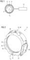
- the Fig. 1 shows purely schematically a basic structure of a measuring arrangement 2.
- a rotor element 8 provided with a coil and ferrite core 9 is surrounded by an antenna holder 12, on which a signal receiver 14 is arranged circumferentially.
- the signal receiver 14 forms a loop on the antenna holder 12.
- the signal receiver 14 continues to a signal evaluation unit 16.
- the signal evaluation unit 16 is attached to the antenna holder 12, which is in the Figure 1 is not shown.
- the signal receiver 16, the antenna holder 12 and the evaluation unit 16 are part of a stator antenna unit 10, which functionally forms the counterpart to the rotor element 8 with coil and ferrite core 9.
- the signal receiver 14 can in this case be designed as a copper wire or copper strip and can be provided with enveloping insulation.
- the rotor element 8 is rotatable about an axis of rotation A D , so that the axis of rotation A D describes an axial direction D. A possible direction of rotation of the rotor element 8 is symbolized by the curved arrow.
- the rotor element 8 can be, for example, a transmission shaft.
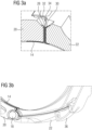
- the Figure 2 shows the antenna holder 12 of a stator antenna unit 10 as a detail in a perspective view.
- the antenna holder 12 is essentially ring-shaped formed and is composed of two half-shell elements 20, 22 in two parts. Both half-shell elements 20, 22 are pivotally connected to one another at one end via a hinge 18 and are connected to one another via a separating point 32 at their other ends, which are essentially diametrically opposite to the hinge 18. Via the separation point 32, the respective ends of the half-shell elements 20, 22 can be released from one another after releasing a locking mechanism 46, so that the half-shell elements 20, 22 can be pivoted relative to one another about a pivot axis As of the hinge 18.
- the antenna holder 12 forms a receiving pocket 36 on one of the half-shell elements 20, 22 for receiving and holding the evaluation unit 16.
- the evaluation unit is in the Figure 2 not shown.
- the antenna holder 12 also has several axially directed and circumferentially distributed openings 38 through which oil can flow, for example from and to a bearing, during operation.
- a circumferential channel 40 is formed on an inner peripheral surface of the antenna holder 12, which serves to accommodate the signal receiver 14, which is in the Figure 2 however, is not shown.
- the channel 40 can be designed as a groove and, viewed in cross section, can be designed to be dovetail-shaped, so that the signal receiver 14 can be easily clicked in and is held in a form-fitting manner relative to the antenna holder 12.
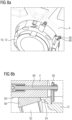
- the Figures 3a) and 3b ) show details of the course of the signal receiver 14 in the area of the separation point 32 - Figure 3a ) - and in the area of the hinge 18 up to the receiving pocket 36 - Figure 3b ).
- the signal receiver 14 is guided radially outwards at the separation point 32, starting from the circumferential course in the channel 40, and two wire ends 28, 30 of the signal receiver 14 open into a funnel 34 formed on the outside circumference of the antenna holder 12. Via the funnel 34, it is easily possible to conductively connect the two wire ends 28, 30 to one another via soldering in the closed position and at least in an operating state of the antenna holder 12. Soldering is not shown here.
- the signal receiver 14 is guided past the hinge 18 in the radial direction and then again in the circumferential direction or in the tangential direction to the receiving pocket 36 to the evaluation unit 16 - not shown.
- the Figure 4a shows a further detail of the separation point 32.
- the separation point 32 includes a latching mechanism 46 which is effective between the two half-shell elements 20, 22 so that they do not unintentionally move into the open position.
- the latching mechanism 46 can be unlocked by inserting a pin 48, so that the two half-shell elements 20, 22 can then be pivoted into the open position.
- the Figure 4b shows a view of the area of the antenna holder 12, in which the signal receiver 14 is guided by the hinge 18 to the evaluation unit 16 located in the receiving pocket 36.
- the signal receiver 14 runs between the hinge 18 and the receiving pocket in a guide channel 42.
- the Figures 5a) and 5b ) show detailed views of the antenna holder 12 and the signal receiver 14 in the area of the hinge 18.
- the Figure 5a ) shows the antenna holder 12 in the closed position, in which the two half-shell elements 20, 22 form a ring over the closed separation point 32 - not shown.
- the Figure 5b ) shows the antenna holder 12 in the open position, in which the half-shell elements 20, 22 are pivoted towards each other via the hinge 18.
- a recess 26 is formed up to the axis of rotation A s of the hinge 18, for receiving the signal receiver 14 guided in the direction of the signal evaluation unit 16.
- the Figure 6a shows a further detail of the antenna holder 12, namely a stop 24, which limits pivoting from the closed position into the open position of the two half-shell elements 20, 22.
- the stop 24 is arranged on the outside circumference in the area of the hinge 18.
- the Figure 6b shows the two half-shell elements 20, 22 of the antenna holder 12 in the open position, in which further swinging open is prevented by the stop 24.
- a value of an angle by which both half-shell elements 20, 22 in the hinge 18 can be pivoted relative to one another into the open position can be, for example, 70°.
- the Figures 7a) and 7b ) show further details of the evaluation unit 16 located in the receiving pocket 36.
- the evaluation unit 16 has a positive coding 44 for clear positioning in the receiving pocket 36.
- the Figures 8a) and 8b ) show the stator antenna unit 10 in an assembly with a gear housing structure 4.
- the gear housing structure 4 is formed in the present case by a housing side wall.
- a bearing bore 50 is formed in the housing side wall 4, in which a rolling bearing 52 is seated in a known manner, see Figure 8b ).
- a transmission shaft that is rotatably held in the rolling bearing 52 relative to the transmission housing structure 4 is not shown here.
- the stator antenna unit 10 is held against the housing side wall 4 from an inside.
- the antenna holder 12 forms a circumferential or partially circumferential collar 54 which projects into the bearing bore 50.
- the antenna holder 12 is supported circumferentially in the bearing bore 50 via the collar 54 and rests axially against the bearing outer ring 56 of the rolling bearing 52. Furthermore, several tabs 58 are provided over the circumference of the antenna holder 12. The antenna holder 12 and thus the entire stator antenna unit 10 is held relative to the housing side wall 4 via the tabs 58 and a corresponding number of axial pins 60, with the axial and radial positioning, as already described, via the contact of the collar 54 within the bearing bore 50 and against the bearing outer ring 56.
- the Figure 9 shows a further representation of the stator antenna unit 10 in an assembly with a gear housing structure 4 in a perspective view. Shown is a gear housing 4, in which several gear components 6, for example in the form of Gear shafts and gears are included.
- a stator antenna unit 10 is, as described, arranged on a housing side wall 4 between this and a gear 64, the stator antenna unit 10 being arranged surrounding the gear shaft 62.
- the transmission shaft 62 has a coil and ferrite core 9 as described above and thus forms a rotor element 8.
- the stator antenna unit 10 and the rotor element 8 together form a measuring arrangement 2.
- the Figure 10 shows a schematic structure of an embodiment of the claimed industrial application 70, which includes a drive unit 72, which can be designed as an electric motor, internal combustion engine or hydraulic motor.
- the drive unit 72 provides a drive power via a drive shaft 74, which can be transmitted to an output unit 78 via a gearbox with a gearbox structure 4 and an output shaft 76.
- the transmission housing structure 4 has a measuring arrangement 2 as described above with a stator antenna unit 10 and a rotor element 8.
Landscapes
- Arrangements For Transmission Of Measured Signals (AREA)
Abstract
Statorantennen-Einheit 10 zur Montage in einer Getriebegehäusestruktur 4 und zur Wechselwirkung mit einem in der Getriebegehäusestruktur 4 an einem Getriebebauteil 6 angeordneten und eine Axialrichtung beschreibenden Rotorelement 8, mit einem ringförmigen Antennenhalter 12, einem umfänglich an dem Antennenhalter 12 verlaufenden Signalempfänger 14, einer mit dem Signalempfänger 14 elektrisch und signaltechnisch verbundene und an dem Antennenhalter 12 befestigte Signalauswerteeinheit 16. Der Antennenhalter 12 ist mehrteilig ausgeführt zwischen einer umfänglich geschlossenen Stellung und einer umfänglich geöffneten Stellung über ein Scharnier 18 schwenkbar. Die Statorantennen-Einheit 10 kann mit ihren Komponenten vollständig in einem Getriebe integriert werden und kann universell eingesetzt werden, da sie für unterschiedliche Getriebebaureihen durch reine Skalierung als Serienlösung eingesetzt werden kann.Stator antenna unit 10 for mounting in a transmission housing structure 4 and for interaction with a rotor element 8 arranged in the transmission housing structure 4 on a transmission component 6 and describing an axial direction, with an annular antenna holder 12, a signal receiver 14 extending circumferentially on the antenna holder 12, one with the Signal receiver 14 electrically and signal-technically connected signal evaluation unit 16 attached to the antenna holder 12. The antenna holder 12 is designed in several parts and can be pivoted between a circumferentially closed position and a circumferentially open position via a hinge 18. The stator antenna unit 10 can be completely integrated with its components in a transmission and can be used universally, as it can be used as a series solution for different transmission series through pure scaling.
Description
Die Erfindung betrifft eine Statorantennen-Einheit zur Montage in einer Getriebegehäusestruktur und zur Wechselwirkung mit einem in der Getriebegehäusestruktur an einem Getriebebauteil angeordneten und eine Axialrichtung beschreibenden Rotorelement, mit einem ringförmigen Antennenhalter, einem umfänglich an dem Antennenhalter verlaufenden Signalempfänger und einer mit dem Signalempfänger elektrisch und signaltechnisch verbundenen Signalauswerteeinheit.The invention relates to a stator antenna unit for mounting in a transmission housing structure and for interaction with a rotor element arranged in the transmission housing structure on a transmission component and describing an axial direction, with an annular antenna holder, a signal receiver running circumferentially on the antenna holder and a signal receiver connected to the signal receiver electrically and in terms of signaling technology connected signal evaluation unit.
Bei mechanisch hochbelasteten Bauteilen, wie beispielsweise Getrieben, ist es seit längerem üblich Belastungszustände sensorisch zu erfassen und zu überwachen. Es werden Zustandsgrößen wie Drehmoment, Temperaturen oder Schwingungen erfasst. Die Zustandsgrößen müssen in der Regel auf oder in einem rotierenden Bauteil über entsprechende Sensorkomponenten abgegriffen werden, auf ein stehendes Bauteil übertragen werden und schließlich außerhalb des Getriebes bereitgestellt werden. Hierbei ist es außerdem erforderlich, die Sensorkomponenten mit Energie, d.h. Spannung und Strom, zu versorgen. In der
Es ist die Aufgabe der Erfindung Maßnahmen aufzuzeigen, die eine verbesserte Anordnung und ein verbessertes Zusammenwirken von Sensorkomponenten in den beschriebenen Anwendungen ermöglichen.It is the object of the invention to show measures that enable an improved arrangement and improved interaction of sensor components in the applications described.
Die Lösung der Aufgabe erfolgt durch eine Statorantennen-Einheit mit den Merkmalen des Anspruchs 1. Bevorzugte Ausgestaltungen sind in den Unteransprüchen und der nachfolgenden Beschreibung angegeben, die jeweils einzeln oder in Kombination einen Aspekt der Erfindung darstellen können. Wenn ein Merkmal in Kombination mit einem anderen Merkmal dargestellt wird, dient dies nur der vereinfachten Darstellung der Erfindung und soll keinesfalls bedeuten, dass dieses Merkmal nicht auch ohne das andere Merkmal eine Weiterbildung der Erfindung sein kann.The problem is solved by a stator antenna unit with the features of claim 1. Preferred embodiments are specified in the subclaims and the following description, which can each represent an aspect of the invention individually or in combination. If a feature is shown in combination with another feature, this only serves to simplify the presentation of the invention and is in no way intended to mean that this feature cannot be a further development of the invention without the other feature.
Eine Ausführungsform betrifft eine Statorantennen-Einheit zur Montage in einer Getriebegehäusestruktur und zur Wechselwirkung mit einem in der Getriebegehäusestruktur an einem Getriebebauteil angeordneten und eine Axialrichtung beschreibenden Rotorelement, umfassend einen ringförmigen Antennenhalter, einen umfänglich an dem Antennenhalter verlaufenden Signalempfänger eine mit dem Signalempfänger elektrisch und signaltechnisch verbundene und an dem Antennenhalter befestigte Signalauswerteeinheit, wobei der Antennenhalter mehrteilig ausgeführt zwischen einer umfänglich geschlossenen Stellung und einer umfänglich geöffneten Stellung über ein Scharnier schwenkbar ist.One embodiment relates to a stator antenna unit for mounting in a transmission housing structure and for interaction with a rotor element arranged in the transmission housing structure on a transmission component and describing an axial direction, comprising an annular antenna holder, a signal receiver running circumferentially on the antenna holder, and an electrically and signally connected signal receiver to the signal receiver and a signal evaluation unit attached to the antenna holder, the antenna holder being designed in several parts and being pivotable via a hinge between a circumferentially closed position and a circumferentially open position.
Bei der Getriebegehäusestruktur kann es sich um eine Getriebegehäuse handeln, das mehrteilig aufgebaut sein kann. Es können beispielsweise zwei über jeweilige Verbindungsflansche gegeneinander gesetzte Gehäusehälften vorgesehen sein. Es kann auch ein hauptsächliches Gehäuseteil vorgesehen sein, gegen das ein Gehäusedeckel gesetzt wird, um ein geschlossenes Getriebegehäuse zu erhalten. Die Gehäusehälften beziehungsweise das Gehäuseteil können wannenförmig ausgebildet sein. Das Getriebegehäuse kann jeweilige als Bohrungen ausgeführte Wellendurchführungen für eine oder mehrere Antriebswellen und eine oder mehrere Abtriebswellen ausbilden. In einer Bohrung kann eine Lager zur Lagerung einer der Wellen aufgenommen sein. In einem unteren Bereich des Getriebegehäuses kann ein Ölreservoir zur Aufnahme zumindest ein Teil einer Ölfüllung vorgesehen sein. Die Angaben oben und unten beziehen sich auf das Erdschwerefeld und auf die regelmäßige Einbauposition während des bestimmungsgemäßen Gebrauchs des Getriebes.The gearbox structure can be a gearbox that can be constructed in several parts. For example, two housing halves placed against each other via respective connecting flanges can be provided. A main housing part can also be provided, against which a housing cover is placed in order to obtain a closed gear housing. The housing halves or the housing part can be trough-shaped. The gearbox housing can form respective shaft bushings designed as bores for one or more drive shafts and one or more output shafts. A bearing for supporting one of the shafts can be accommodated in a bore. An oil reservoir for receiving at least part of an oil filling can be provided in a lower region of the transmission housing. The information above and below refers to the earth's gravity field and the regular installation position during intended use of the gearbox.
Bei einem Getriebebauteil handelt es sich beispielsweise um ein rotierendes Bauteil, das durch seine Rotationsachse eine Axialrichtung beschreibt. Bei einem solchen Bauteil kann es sich um eine antriebs- oder abtriebsseitige Getriebewelle, ein Wälz- oder Gleitlager oder auch ein Verzahnungselement handeln. Bei dem Rotorelement kann es sich beispielsweise um eine auf einer Getriebewelle angeordnete Spule mit einem Ferritkern handeln.A transmission component is, for example, a rotating component that describes an axial direction through its axis of rotation. Such a component can be a drive or output side gear shaft, a roller or plain bearing or even a toothed element. The rotor element can be, for example, a coil with a ferrite core arranged on a transmission shaft.
Der ringförmige Antennenhalter ist umfänglich um das Rotorelement angeordnet, um mit diesem in eine Wechselwirkung zu treten. Der Antennenhalter ist zweckmäßigerweise gegenüber der Getriebegehäusestruktur gehalten und positioniert. Insbesondere kann eine Positionierung einen radialen und axialen Toleranzausgleich beinhalten. Der Begriff "ringförmig" kann auch als "kreisförmig" bezeichnet werden, sofern dies nicht im streng geometrischen Sinne verstanden wird. Bevorzugt ist allerdings, dass eine Innenumfangsfläche des Antennenhalters geometrisch kreisförmig ist und im Bereich dieser Innenumfangsfläche der umfänglich an dem Antennenhalter verlaufenden Signalempfänger angeordnet ist. Bevorzugt ist der Signalempfänger in die Innenumfangsfläche eingelassen, insbesondere in einer umfänglich verlaufenden Nut bzw. in einem Kanal. Die Nut bzw. der Kanal kann im Querschnitt betrachtet schwalbenschwanz-förmig gestaltet sein, so dass der Signalempfänger einfach eingeklickt werden kann und formschlüssig gegenüber dem Antennenhalter gehalten ist. Alternativ kann auch eine rechteckige, umlaufende Nut mit mehreren über den Umfang verteilte Nocken vorgesehen sein, hinter die der Signalempfänger geklemmt werden kann. Wiederum alternativ kann der Signalempfänger auch in eine rechteckige, umlaufende Nut eingelegt und anschließend eingeklebt werden. Der Antennenhalter kann in einem 3-D-Druckverfahren hergestellt sein. Alternativ kann er im Spritzgussverfahren, Vakuumgussverfahren oder anderen Gussverfahren hergestellt werden. Denkbar ist auch, dass er in einem konventionellen, spanenden Verfahren hergestellt wird.The annular antenna holder is arranged circumferentially around the rotor element in order to interact with it. The antenna holder is expediently held and positioned relative to the transmission housing structure. In particular, positioning can include radial and axial tolerance compensation. The term "annular" can also be referred to as "circular" unless understood in a strictly geometric sense. However, it is preferred that an inner peripheral surface of the antenna holder is geometrically circular and is arranged in the area of this inner peripheral surface of the signal receiver running circumferentially on the antenna holder. The signal receiver is preferably embedded in the inner circumferential surface, in particular in a circumferential groove or in a channel. The groove or channel can be in Viewed in cross section, it can be designed to be dovetail-shaped so that the signal receiver can be easily clicked in and is held in a form-fitting manner relative to the antenna holder. Alternatively, a rectangular, circumferential groove with several cams distributed over the circumference can also be provided, behind which the signal receiver can be clamped. Alternatively, the signal receiver can also be inserted into a rectangular, circumferential groove and then glued in. The antenna holder can be manufactured using a 3D printing process. Alternatively, it can be manufactured using injection molding, vacuum casting or other casting processes. It is also conceivable that it is manufactured using a conventional, machining process.
Die Auswerteeinheit beinhaltet vorliegend die Statorelektronik. Über die Auswerteeinheit wird über einen Wechselstrom ein auf das Rotorelement wirkende Induktionsfeld erzeugt. Hierüber wird das Rotorelement mit einer Spannung versorgt. Die Auswerteeinheit moduliert über den Wechselstrom das Induktionsfeld, so dass über Modulation die jeweiligen Messdaten der zu erfassenden Zustandsgrößen übertragen werden können. Der Signalempfänger umfasst bevorzugt ein Kupferkabel oder ein Kupferband, welches vorisoliert bzw. kaschiert ist, so dass während einer Montage Isolations- und Abdeckschritte nicht erforderlich sind. Das Kupferkabel bzw. Kupferband kann über den Antennenhalter sowohl in axialer wie auch radialer Richtung im richtigen Abstand über dem Rotorelement fixiert werden. Das Kupferkabel bzw. Kupferband ist zweckmäßigerweise als Schleife gelegt. Über den Antennenhalter ist sichergestellt, dass die Schleife zur Vermeidung von Energieunterbrechungen oder Kommunikationsfehlern einen geschlossenen Kreis bildet und während einer Betriebssituation weder eingedrückt, noch verlängert, noch in irgendeiner anderen Art und Weise beeinträchtigt wird. Die Schleife ist über den Antennenhalter derart eingebunden, dass keine mechanischen Kräfte Geometrieänderungen oder Beschädigungen herbeiführen können, sowie Positionsveränderung axial und radial ausgeschlossen sind. Dadurch, dass die Auswerteeinheit an dem Antennenhalter befestigt ist, kann sichergestellt werden, dass Auswerteeinheit und Schleife des Signalempfängers in der Nähe zueinander positioniert werden können.In this case, the evaluation unit contains the stator electronics. An induction field acting on the rotor element is generated via the evaluation unit using an alternating current. This supplies the rotor element with voltage. The evaluation unit modulates the induction field via the alternating current, so that the respective measurement data of the state variables to be recorded can be transmitted via modulation. The signal receiver preferably comprises a copper cable or a copper tape, which is pre-insulated or laminated, so that insulation and covering steps are not required during assembly. The copper cable or copper tape can be fixed at the correct distance above the rotor element in both the axial and radial directions using the antenna holder. The copper cable or copper tape is expediently laid as a loop. The antenna holder ensures that the loop forms a closed circuit to avoid power interruptions or communication errors and is neither compressed, extended, nor impaired in any other way during an operating situation. The loop is integrated via the antenna holder in such a way that no mechanical forces can cause geometry changes or damage, and axial and radial position changes are excluded. The fact that the evaluation unit is attached to the antenna holder can ensure that the evaluation unit and the loop of the signal receiver can be positioned close to one another.
Die Statorantennen-Einheit ist zweckmäßigerweise geerdet. Hierfür ist eine Verbindung zu der Getriebegehäusestruktur vorgesehen, welches das Erdpotential annimmt. Um die Statorantennen-Einheit mit der Getriebegehäusestruktur zu verbinden, kann ein Erdungsband von der Auswerteeinheit in einen Kanal gelegt werden. Auf das Ende des Erdungsbandes drückt beispielsweise ein Metallblech, welches über eine Schraube mit der Getriebegehäusestruktur verbunden ist. Durch eine Feder unterhalb des Schraubenkopfes kann eine dauerhaft definierte Anpresskraft erzeugt werden. Andere Verbindungsmöglichkeiten des Erdungsbandes sind auch möglich.The stator antenna unit is expediently grounded. For this purpose, a connection to the transmission housing structure is provided, which assumes ground potential. In order to connect the stator antenna unit to the gearbox structure, a grounding strap can be placed in a channel by the evaluation unit. For example, a metal sheet, which is connected to the transmission housing structure via a screw, presses on the end of the grounding strap. A spring underneath the screw head can generate a permanently defined contact force. Other connection options for the ground strap are also possible.
Bei der zweiteiligen Ausgestaltung des Antennenhalters kann dieser aus zwei oder mehreren im Wesentlichen gleichen Teilen zusammengesetzt sein. Vorgesehen ist, dass eines dieser Teile die Auswerteinheit trägt. Die zweiteilige Ausgestaltung hat insbesondere den Vorteil, dass die Statorantennen-Einheit um eine Getriebewelle montiert werden kann, die bereits in einer Getriebegehäusestruktur montiert wurde. Insbesondere kann die Statorantennen-Einheit auch im Zuge von Nachrüstungen von bereits im Betrieb befindlichen Getrieben montiert werden. Über das Scharnier kann der zweiteilige Antennenhalter geöffnet bzw. aufgeklappt werden, um in über die Getriebewelle zu führen bzw. zu stülpen. Im Anschluss kann der Antennenhalter wieder geschlossen werden. Hierfür kann ein Einrastmechanismus vorgesehen sein. In einer bevorzugten Ausgestaltung ist vorgesehen, dass der Antennenhalter über zwei Halbschalenelemente zweiteilig ausgeführt ist und die zwei Halbschalenelemente über das Scharnier miteinander verbunden zwischen der umfänglich geschlossenen Stellung und der umfänglich geöffneten Stellung schwenkbar sind. Hierbei kann vorgesehen sein, dass jedes Halbschalenelemente im Wesentlichen 180° eines vollständigen Umfangs beschreiben. Alternativ ist auch es auch möglich, dass drei Schalenelemente vorgesehen sind, die dann über zwei Scharnieren schwenkbar miteinander verbunden werden. Für bestimmte Anwendungen ist auch denkbar, dass mehr als drei Schalenelemente gelenkig miteinander verbunden sind.In the two-part design of the antenna holder, it can be composed of two or more essentially equal parts. It is intended that one of these parts carries the evaluation unit. The two-part design has the particular advantage that the stator antenna unit can be mounted around a gear shaft that has already been mounted in a gear housing structure. In particular, the stator antenna unit can also be installed as part of retrofitting gearboxes that are already in operation. The two-part antenna holder can be opened or unfolded using the hinge in order to be guided or slipped over the transmission shaft. The antenna holder can then be closed again. A latching mechanism can be provided for this. In a preferred embodiment it is provided that the antenna holder is designed in two parts via two half-shell elements and the two half-shell elements are connected to one another via the hinge and can be pivoted between the circumferentially closed position and the circumferentially open position. It can be provided here that each half-shell element essentially describes 180° of a complete circumference. Alternatively, it is also possible for three shell elements to be provided, which are then pivotally connected to one another via two hinges. For certain applications it is also conceivable that more than three shell elements are connected to one another in an articulated manner.
Die vorliegend beschriebene Statorantennen-Einheit kann mit ihren Komponenten vollständig in einem Getriebe integriert werden und kann universell eingesetzt werden, da sie für unterschiedliche Getriebebaureihen durch reine Skalierung als Serienlösung eingesetzt werden kann. Konstruktiver Aufwand verringert sich auf ein Minimum. Die Montage der vorkonfektionierten Statorantennen-Einheit lässt sich sehr einfach in den typischen Montageprozess der Getriebe eingliedern. Mit der Statorantennen-Einheit wird eine serienfähige Möglichkeit bereitgestellt, mit der Telemetrien für Messsysteme in Getriebebaureihen eingesetzt werden können. Die vollständige Integration der Statorantennen-Einheit führt zu einer stark erhöhten Zuverlässigkeit der Telemetrie.The stator antenna unit described here can be completely integrated with its components in a gearbox and can be used universally, as it can be used as a series solution for different gearbox series through pure scaling. Construction effort is reduced to a minimum. The assembly of the pre-assembled stator antenna unit can be easily integrated into the typical assembly process of the gearbox. The stator antenna unit provides a production-ready option with which telemetry can be used for measuring systems in transmission series. The complete integration of the stator antenna unit leads to a greatly increased reliability of the telemetry.
In einer bevorzugten Ausgestaltung ist vorgesehen, dass ein außenumfänglich auf dem Antennenhalter angeordneter Anschlag ein Schwenken von der geschlossenen Stellung in die geöffnete Stellung begrenzt. Insbesondere kann der Anschlag außen an dem Scharnier angeordnet sein. Durch den Anschlag und die Begrenzung der Schwenkbewegung ist sichergestellt, dass beim Aufschwenken des Antennenhalters in die geöffnete Stellung der Signalempfänger, also beispielsweise das Kupferkabel bzw. Kupferband, nicht beschädigt wird. Insbesondere kann vorgesehen sein, dass der Anschlag ein Aufschwenken der beiden Halbschalenelemente auf etwas 70° begrenzt. Dieser Öffnungswinkel erlaubt es dem Antennenhalter über den Außendurchmesser einer Getriebewelle gestülpt zu werden.In a preferred embodiment it is provided that a stop arranged on the outside circumference of the antenna holder limits pivoting from the closed position into the open position. In particular, the stop can be arranged on the outside of the hinge. The stop and the limitation of the pivoting movement ensure that the signal receiver, for example the copper cable or copper tape, is not damaged when the antenna holder is pivoted into the open position. In particular, it can be provided that the stop limits pivoting of the two half-shell elements to approximately 70°. This opening angle allows the antenna holder to be placed over the outer diameter of a transmission shaft.
In einer zudem bevorzugten Ausgestaltung ist vorgesehen, dass der Signalempfänger im Bereich des Scharniers ausgehend von dem umfänglichen Verlauf in Richtung der Signalauswerteeinheit geführt ist. Hierbei kann der Signalempfänger insbesondere so geführt sein, dass der Signalempfänger ausgehend von dem umfänglichen Verlauf zunächst in radialer Richtung an dem Scharnier vorbeigeführt wird und dann erneut in Umfangsrichtung oder auch in tangentialer Richtung zu der Auswerteeinheit geführt wird. Der Signalempfänger, der bevorzugt als Kupferkabel bzw. Kupferband ausgeführt ist, ist mit der Auswerteeinheit leitend verbunden, wozu bevorzugt eine Lötverbindung dient. Um die Zugänglichkeit zu der Auswerteinheit zum Anbringen der Lötverbindung zu gewährleisten ist eine Zugangsöffnung in dem Antennenhalter vorgesehen. Anstatt dieser Lötverbindung kann auch ein Einklipsen, ein Andrücken oder ein Schraubklemmen vorgesehen sein. Durch die Ausgestaltung, bei der die Auswerteeinheit unmittelbar auf dem Antennenhalter angeordnet ist, kann in vorteilhafter Weise sichergestellt werden, dass eine Länge des Signalempfängers von dem Scharnier bis zu einem Anschluss an die Auswerteeinheit ein Abstandsmaß von 400mm nicht überschreitet.In a further preferred embodiment it is provided that the signal receiver is guided in the area of the hinge, starting from the circumferential course in the direction of the signal evaluation unit. In this case, the signal receiver can in particular be guided in such a way that, starting from the circumferential course, the signal receiver is first guided past the hinge in the radial direction and then guided again in the circumferential direction or also in the tangential direction to the evaluation unit. The signal receiver, which is preferably designed as a copper cable or copper strip, is conductively connected to the evaluation unit, for which purpose a soldered connection is preferably used. In order to ensure accessibility to the evaluation unit for attaching the solder connection, there is an access opening provided in the antenna holder. Instead of this solder connection, clipping, pressing or screw terminals can also be provided. The configuration in which the evaluation unit is arranged directly on the antenna holder can advantageously ensure that a length of the signal receiver from the hinge to a connection to the evaluation unit does not exceed a distance of 400mm.
In einer außerdem bevorzugten Ausgestaltung ist vorgesehen, dass der Antennenhalter im Bereich des Scharniers auf einer Axialseite einen bis zu einer Drehachse des Scharniers verlaufende Aussparung ausbildet, zur Aufnahme des in Richtung der Signalauswerteeinheit geführten Signalempfängers. Durch die Aussparung ist sichergestellt, dass beim Aufschwenken des Antennenhalters in die geöffnete Stellung der Signal empfänger, also beispielsweise das Kupferkabel bzw. Kupferband, nicht gelängt oder gestaucht wird.In a further preferred embodiment it is provided that the antenna holder in the area of the hinge on an axial side forms a recess extending up to an axis of rotation of the hinge for receiving the signal receiver guided in the direction of the signal evaluation unit. The recess ensures that when the antenna holder is swung open into the open position, the signal receiver, for example the copper cable or copper tape, is not elongated or compressed.
Eine bevorzugte Ausgestaltung sieht außerdem vor, dass zwei Drahtenden des Signalempfängers an einer dem Scharnier, bevorzugt diametral, gegenüberliegenden Trennstelle des Antennenhalters ausgehend von dem umfänglichen Verlauf nach radial außen geführt sind. Bei der Trennstelle handelt es sich um den Bereich in dem beide Halbschalenelemente in geschlossener Stellung des Antennenhalters aufeinandertreffen und in dem sie sich beim Öffnen auseinanderbewegen. Der Einrastmechanismus kann an der Trennstelle angeordnet sein. An der Trennstelle weist der Signalempfänger zwei Drahtenden auf, die anfänglich nicht miteinander verbunden sind und erst nach erfolgter Montage in einer Getriebestruktur leitend miteinander verbunden werden. Zweckmäßigerweise liegen die beiden Drahtenden im Bereich der Trennstelle in der geschlossenen Stellung des Antennenhalters unmittelbar oder weitestgehend nah beieinander, so dass zu einem späteren Zeitpunkt ohne Weiteres ein Verbinden beider Drahtenden erfolgen kann. In konkreter Ausgestaltung können hierzu die zwei Drahtenden in einem außenumfänglich auf dem Antennenhalter ausgebildeten Trichter münden. Hierdurch kann durch einfache Maßnahmen erreicht werden, dass die zwei Drahtenden in der geschlossenen Stellung und zumindest in einem Betriebszustand des Antennenhalters über eine Verlötung leitend miteinander verbunden sind. Der Trichter erleichtert in vorteilhafter Weise die Applikation eines Lötmittels und die gezielte Zuführung zu den beiden Drahtenden.A preferred embodiment also provides that two wire ends of the signal receiver are guided radially outwards at a separation point of the antenna holder that is opposite the hinge, preferably diametrically, starting from the circumferential course. The separation point is the area in which both half-shell elements meet in the closed position of the antenna holder and in which they move apart when opened. The latching mechanism can be arranged at the separation point. At the separation point, the signal receiver has two wire ends that are not initially connected to one another and are only conductively connected to one another after assembly in a transmission structure. The two wire ends expediently lie directly or largely close to one another in the area of the separation point in the closed position of the antenna holder, so that both wire ends can easily be connected at a later point in time. In a specific embodiment, the two wire ends can open into a funnel formed on the outside circumference of the antenna holder. In this way, simple measures can be used to ensure that the two wire ends are conductive to one another via soldering in the closed position and at least in an operating state of the antenna holder are connected. The funnel advantageously facilitates the application of a solder and the targeted feeding to the two wire ends.
In einer weiterhin bevorzugten Ausgestaltung ist vorgesehen, dass die Signalauswerteeinheit in einer Aufnahmetasche des Antennenhalters mit einem Kunstharz vergossen aufgenommen ist. Hierdurch ist sichergestellt, dass die Auswerteeinheit sicher und fest an dem Antennenhalter angebracht ist. Zur eindeutigen Positionierung der Auswerteeinheit während des Zusammensetzens ist die Auswerteeinheit bevorzugt über eine formschlüssige Codierung in der Aufnahmetasche aufgenommen. Im Anschluss an das Einsetzen der Auswerteeinheit erfolgt das Vergießen mit Kunstharz.In a further preferred embodiment, it is provided that the signal evaluation unit is accommodated in a receiving pocket of the antenna holder, cast with a synthetic resin. This ensures that the evaluation unit is securely and firmly attached to the antenna holder. For clear positioning of the evaluation unit during assembly, the evaluation unit is preferably accommodated in the receiving pocket via a positive coding. After inserting the evaluation unit, it is cast with synthetic resin.
In einer zudem bevorzugten Ausgestaltung ist vorgesehen, dass in dem Antennenhalter zumindest ein axial gerichteter Durchbruch vorgesehen ist. Hierdurch ist sichergestellt, dass die Statorantennen-Einheit beispielsweise axial vor einem Lager angeordnet werden kann und durch den zumindest einen axialen Durchbruch ein Ölfluss von und zu dem Lager gewährleistet ist. Ein Ölstau wird somit vermieden.In a further preferred embodiment it is provided that at least one axially directed opening is provided in the antenna holder. This ensures that the stator antenna unit can be arranged, for example, axially in front of a bearing and that an oil flow from and to the bearing is ensured by the at least one axial breakthrough. An oil jam is thus avoided.
Die Aufgabe wird ferner gelöst durch ein Getriebe mit einem Getriebegehäuse, zumindest eine in dem Getriebegehäuse über ein Wälzlager drehbar gelagerte Welle, wobei das Wälzlager in einer Gehäusebohrung des Getriebegehäuses einsitzt und zumindest eine die Welle umgebende Statorantennen-Einheit wie zuvor beschrieben vorgesehen ist. Hierbei kann vorgesehen sein, dass der Antennenhalter mit einem zumindest teilweise umlaufenden Kragen in die Gehäusebohrung hineinragt. Beispielsweise kann der Kragen teilumfänglich etwa 200° eines Gesamtumfangs abdecken. In konkreter Ausgestaltung kann vorgesehen sein, dass der Antennenhalter in der Gehäusebohrung sich umfänglich abstützend einsitzt und axial gegen einen Lagerring des Wälzlagers anliegt. Alternativ kann auch vorgesehen sein, dass die axiale Abstützung über eine in der Gehäusebohrung einsitzende Buchse erfolgt. Über die umfängliche Abstützung wird hierbei ein Positionieren des Antennenhalters in radialer Richtung bezogen auf das Getriebegehäuse erreicht. Über die Anlage des Antennenhalter gegen einen Lagerring des Wälzlagers, was beispielsweise der Außenlagerring sein kann, wird ein Positionieren des Antennenhalters in axialer Richtung bezogen auf das Getriebegehäuse erreicht. Vorn Vorteil ist hierbei, dass die Telemetrie sich weitestgehend in unmittelbarer Nähe der Lagerung befindet, erhöht sich die Einsetzbarkeit der Telemetrie. Es lassen sich viele verschiedene relevante Messgrößen aufnehmen und mit Hilfe der Telemetrie übertragen. Messgrößen sind beispielsweise Drehmoment, Axialkräfte, Biegekräfte, Zahnfußspannungen, Temperaturen am Lagerinnenring, Spannungen in Kerbnähe.The object is further achieved by a transmission with a transmission housing, at least one shaft rotatably mounted in the transmission housing via a roller bearing, the roller bearing being seated in a housing bore of the transmission housing and at least one stator antenna unit surrounding the shaft being provided as described above. It can be provided here that the antenna holder projects into the housing bore with an at least partially circumferential collar. For example, the collar can partially cover approximately 200° of a total circumference. In a specific embodiment, it can be provided that the antenna holder sits in the housing bore in a circumferential supporting manner and rests axially against a bearing ring of the rolling bearing. Alternatively, it can also be provided that the axial support takes place via a bushing seated in the housing bore. The circumferential support enables the antenna holder to be positioned in the radial direction in relation to the gearbox housing. About the installation of the antenna holder against a bearing ring of the rolling bearing, which can be the outer bearing ring, for example, positioning of the antenna holder in the axial direction with respect to the gearbox housing is achieved. The advantage here is that the telemetry is largely located in the immediate vicinity of the storage, which increases the usability of the telemetry. Many different relevant measurements can be recorded and transmitted using telemetry. Measured variables include, for example, torque, axial forces, bending forces, tooth root stresses, temperatures on the bearing inner ring, and stresses near the notch.
Auch wird die zugrundeliegende Aufgabenstellung gelöst durch einen Antriebsstrang umfassend eine als Antriebswelle ausgebildete erste Welle, die über einem Getriebe mit einer als Abtriebswelle ausgebildeten zweiten Welle drehmomentübertragend gekoppelt ist, wobei das Getriebe wie zuvor beschrieben ausgebildet ist.The underlying task is also solved by a drive train comprising a first shaft designed as a drive shaft, which is torque-transmittingly coupled via a gear to a second shaft designed as an output shaft, the gear being designed as previously described.
Gleichermaßen wird die Aufgabenstellung gelöst durch eine Industrieapplikation, umfassend eine Antriebseinheit, die mit einer Abtriebseinheit über ein Getriebe drehmomentübertragend verbunden ist, wobei das Getriebe wie zuvor beschrieben ausgebildet ist.Likewise, the task is solved by an industrial application comprising a drive unit which is connected to an output unit via a transmission to transmit torque, the transmission being designed as described above.
Nachfolgend wird die Erfindung unter Bezugnahme auf die anliegenden Zeichnungen anhand bevorzugter Ausführungsbeispiele exemplarisch erläutert, wobei die nachfolgend dargestellten Merkmale sowohl jeweils einzeln als auch in Kombination einen Aspekt der Erfindung darstellen können. Es zeigen:
-
Fig. 1 : einen schematischen und prinzipiellen Aufbau einer Messanordnung; -
Fig. 2 : einen Antennenhalter als Einzelheit in perspektivischer Darstellung; -
Fig. 3a ), 3b): Detaillierungen des Verlaufs des Signalempfängers; -
Fig. 4a ): eine Detaillierung der Trennstelle des Antennenhalters; -
Fig. 4b ): eine Ansicht des Bereichs des Antennenhalters zwischen Scharnier und Aufnahmetasche; -
Fig. 5a ), 5b): Detailansichten des Antennenhalters und des Signalempfängers im Bereich des Scharniers; -
Fig. 6a ), 6b): eine weitere Detaillierung des Antennenhalters und des Antennenhalters in geöffneter Stellung; -
Fig. 7a ), 7b): weitere Detaillierungen der in der Aufnahmetasche einsitzenden Auswerteeinheit; -
Fig. 8a ), 8b), 9: die Statorantennen-Einheit in einem Zusammenbau mit einer Getriebegehäusestruktur und -
Fig. 10 : eine schematische Darstellung einer Industrieapplikation mit einer Messanordnung mit Statorantennen-Einheit.
-
Fig. 1 : a schematic and basic structure of a measuring arrangement; -
Fig. 2 : an antenna holder as a detail in a perspective view; -
Fig. 3a ), 3b): Details of the course of the signal receiver; -
Fig. 4a ): a detailing of the separation point of the antenna holder; -
Fig. 4b ): a view of the area of the antenna holder between the hinge and the storage pocket; -
Fig. 5a ), 5b): Detailed views of the antenna holder and the signal receiver in the area of the hinge; -
Fig. 6a ), 6b): a further detail of the antenna holder and the antenna holder in the open position; -
Fig. 7a ), 7b): further details of the evaluation unit located in the receiving pocket; -
Fig. 8a ), 8b), 9: the stator antenna unit in an assembly with a gear housing structure and -
Fig. 10 : a schematic representation of an industrial application with a measuring arrangement with a stator antenna unit.
Die
Die
Der Antennenhalter 12 bilden auf einem der Halbschalenelemente 20, 22 eine Aufnahmetasche 36 zur Aufnahme und zum Halten der Auswerteeinheit 16 aus. Die Auswerteeinheit ist in der
Die
Die
Die
Die
Die
Die
Die
Die
Die
- 22
- MessanordnungMeasuring arrangement
- 44
- GetriebegehäusestrukturGearbox structure
- 66
- GetriebebauteilTransmission component
- 88th
- RotorelementRotor element
- 99
- Spule und FerritkernCoil and ferrite core
- 1010
- Statorantennen-EinheitStator antenna unit
- 1212
- AntennenhalterAntenna holder
- 1414
- SignalempfängerSignal receiver
- 1616
- SignalauswerteeinheitSignal evaluation unit
- 1818
- Scharnierhinge
- 2020
- HalbschalenelementHalf-shell element
- 2222
- HalbschalenelementHalf-shell element
- 2424
- Anschlagattack
- 2626
- Aussparungrecess
- 2828
- Drahtendewire end
- 3030
- Drahtendewire end
- 3232
- Trennstelleseparation point
- 3434
- Trichterfunnel
- 3636
- AufnahmetascheRecording bag
- 3838
- Durchbruchbreakthrough
- 4040
- Kanalchannel
- 4242
- FührungskanalGuide channel
- 4444
- CodierungCoding
- 4646
- EinrastmechanismusSnap mechanism
- 4848
- StiftPen
- 5050
- Lagerbohrungbearing bore
- 5252
- Wälzlagerroller bearing
- 5454
- Kragencollar
- 5656
- LageraußenringBearing outer ring
- 5858
- Laschetab
- 6060
- AxialstiftAxial pin
- 6262
- GetriebewelleTransmission shaft
- 6464
- Zahnradgear
Claims (15)
Priority Applications (2)
| Application Number | Priority Date | Filing Date | Title |
|---|---|---|---|
| EP22168811.2A EP4266485A1 (en) | 2022-04-19 | 2022-04-19 | Stator antenna unit for a measuring arrangement |
| PCT/EP2023/058774 WO2023202874A1 (en) | 2022-04-19 | 2023-04-04 | Stator antenna unit for a measuring arrangement |
Applications Claiming Priority (1)
| Application Number | Priority Date | Filing Date | Title |
|---|---|---|---|
| EP22168811.2A EP4266485A1 (en) | 2022-04-19 | 2022-04-19 | Stator antenna unit for a measuring arrangement |
Publications (1)
| Publication Number | Publication Date |
|---|---|
| EP4266485A1 true EP4266485A1 (en) | 2023-10-25 |
Family
ID=81327241
Family Applications (1)
| Application Number | Title | Priority Date | Filing Date |
|---|---|---|---|
| EP22168811.2A Pending EP4266485A1 (en) | 2022-04-19 | 2022-04-19 | Stator antenna unit for a measuring arrangement |
Country Status (2)
| Country | Link |
|---|---|
| EP (1) | EP4266485A1 (en) |
| WO (1) | WO2023202874A1 (en) |
Citations (5)
| Publication number | Priority date | Publication date | Assignee | Title |
|---|---|---|---|---|
| GB2129138A (en) * | 1982-10-01 | 1984-05-10 | Sugar Res Ltd | Inductively coupled load monitoring of rotating shaft |
| EP1920221A1 (en) * | 2005-08-30 | 2008-05-14 | NCTEngineering GmbH | Sensor device, sensor arrangement, and method of measuring a property of an object |
| EP2113930A2 (en) * | 2008-04-30 | 2009-11-04 | Hottinger Baldwin Messtechnik Gmbh | Stator antenna ring |
| EP3696940A1 (en) * | 2019-02-12 | 2020-08-19 | Hitachi, Ltd. | Power reception unit, power transmission unit, and wireless power transfer device |
| EP3786591A1 (en) | 2019-08-30 | 2021-03-03 | Flender GmbH | Sensor unit and transmission comprising at least one such sensor unit |
-
2022
- 2022-04-19 EP EP22168811.2A patent/EP4266485A1/en active Pending
-
2023
- 2023-04-04 WO PCT/EP2023/058774 patent/WO2023202874A1/en active Search and Examination
Patent Citations (5)
| Publication number | Priority date | Publication date | Assignee | Title |
|---|---|---|---|---|
| GB2129138A (en) * | 1982-10-01 | 1984-05-10 | Sugar Res Ltd | Inductively coupled load monitoring of rotating shaft |
| EP1920221A1 (en) * | 2005-08-30 | 2008-05-14 | NCTEngineering GmbH | Sensor device, sensor arrangement, and method of measuring a property of an object |
| EP2113930A2 (en) * | 2008-04-30 | 2009-11-04 | Hottinger Baldwin Messtechnik Gmbh | Stator antenna ring |
| EP3696940A1 (en) * | 2019-02-12 | 2020-08-19 | Hitachi, Ltd. | Power reception unit, power transmission unit, and wireless power transfer device |
| EP3786591A1 (en) | 2019-08-30 | 2021-03-03 | Flender GmbH | Sensor unit and transmission comprising at least one such sensor unit |
Also Published As
| Publication number | Publication date |
|---|---|
| WO2023202874A1 (en) | 2023-10-26 |
Similar Documents
| Publication | Publication Date | Title |
|---|---|---|
| DE4440238B4 (en) | fuel pump | |
| DE60008058T2 (en) | rotary connector | |
| DE10260261A1 (en) | Electrically operated steering device | |
| WO2015044034A2 (en) | Electric machine and connecting unit for an electric machine | |
| DE102018208823A1 (en) | Contacting element for electrically contacting a shaft of an electric drive unit of a motor vehicle, electric drive unit and motor vehicle | |
| DE102005037862B3 (en) | Explosion proof position sensor has shaft joining flat spiral spring and angle encoder in external pressure proor housing with measurement cable drum in unsealed housing | |
| DE3042099A1 (en) | DEVICE FOR TORQUE TRANSMISSION | |
| EP4266485A1 (en) | Stator antenna unit for a measuring arrangement | |
| WO2022017559A1 (en) | Housing for an electric motor, and electric drive unit | |
| EP2643920B1 (en) | Shielding arrangement for a brush-commutated electric motor, and positioning element with an electric motor | |
| DE102009056379B4 (en) | Connection arrangement for a clutch release device of a motor gear unit and mounting method therefor | |
| DE19542047C2 (en) | Torque sensor | |
| WO2011069545A1 (en) | Condition monitoring system of a motor | |
| EP4291427A1 (en) | Integrated axle drive and motor vehicle | |
| WO2022234079A1 (en) | Shaft-grounding device for establishing an electrically conductive connection between a rotatable shaft and a housing | |
| DE112013006102T5 (en) | electric motor | |
| AT522787B1 (en) | Bearing arrangement | |
| WO2021047712A1 (en) | Electrical machine | |
| WO2021190842A1 (en) | Drive unit | |
| DE102017105512A1 (en) | Adjustment device for an internal combustion engine | |
| EP4204699B1 (en) | Bearing element with a sensor and a telemetric device | |
| AT522972A4 (en) | Bearing arrangement | |
| DE102017218743A1 (en) | A method of connecting a torque converter unit to a transmission | |
| DE102017112607A1 (en) | Central release with radial inside sensor | |
| DE202015105245U1 (en) | electric motor |
Legal Events
| Date | Code | Title | Description |
|---|---|---|---|
| STAA | Information on the status of an ep patent application or granted ep patent |
Free format text: STATUS: THE APPLICATION HAS BEEN PUBLISHED |
|
| PUAI | Public reference made under article 153(3) epc to a published international application that has entered the european phase |
Free format text: ORIGINAL CODE: 0009012 |
|
| AK | Designated contracting states |
Kind code of ref document: A1 Designated state(s): AL AT BE BG CH CY CZ DE DK EE ES FI FR GB GR HR HU IE IS IT LI LT LU LV MC MK MT NL NO PL PT RO RS SE SI SK SM TR |
|
| STAA | Information on the status of an ep patent application or granted ep patent |
Free format text: STATUS: THE APPLICATION IS DEEMED TO BE WITHDRAWN |