EP4266403A1 - Active material particles and method for producing active material particles - Google Patents
Active material particles and method for producing active material particles Download PDFInfo
- Publication number
- EP4266403A1 EP4266403A1 EP21906612.3A EP21906612A EP4266403A1 EP 4266403 A1 EP4266403 A1 EP 4266403A1 EP 21906612 A EP21906612 A EP 21906612A EP 4266403 A1 EP4266403 A1 EP 4266403A1
- Authority
- EP
- European Patent Office
- Prior art keywords
- active material
- material particles
- protective layer
- particle
- layer
- Prior art date
- Legal status (The legal status is an assumption and is not a legal conclusion. Google has not performed a legal analysis and makes no representation as to the accuracy of the status listed.)
- Withdrawn
Links
- 239000002245 particle Substances 0.000 title claims abstract description 191
- 239000011149 active material Substances 0.000 title claims abstract description 136
- 238000004519 manufacturing process Methods 0.000 title description 28
- 239000011241 protective layer Substances 0.000 claims abstract description 68
- 239000010410 layer Substances 0.000 claims abstract description 54
- 239000006183 anode active material Substances 0.000 claims description 34
- 239000006182 cathode active material Substances 0.000 claims description 13
- 239000007787 solid Substances 0.000 claims description 6
- 239000000126 substance Substances 0.000 claims description 5
- 238000010438 heat treatment Methods 0.000 claims description 3
- 238000000034 method Methods 0.000 description 27
- 239000000463 material Substances 0.000 description 16
- 230000004048 modification Effects 0.000 description 11
- 238000012986 modification Methods 0.000 description 11
- 230000008569 process Effects 0.000 description 10
- OKTJSMMVPCPJKN-UHFFFAOYSA-N Carbon Chemical compound [C] OKTJSMMVPCPJKN-UHFFFAOYSA-N 0.000 description 9
- 230000001681 protective effect Effects 0.000 description 9
- 229910052751 metal Inorganic materials 0.000 description 8
- 239000002184 metal Substances 0.000 description 8
- 229910052744 lithium Inorganic materials 0.000 description 7
- 239000002243 precursor Substances 0.000 description 7
- 239000000243 solution Substances 0.000 description 6
- WHXSMMKQMYFTQS-UHFFFAOYSA-N Lithium Chemical compound [Li] WHXSMMKQMYFTQS-UHFFFAOYSA-N 0.000 description 5
- 239000003575 carbonaceous material Substances 0.000 description 5
- -1 conductive whiskers Chemical class 0.000 description 5
- 238000002156 mixing Methods 0.000 description 5
- 239000002994 raw material Substances 0.000 description 5
- 229920005989 resin Polymers 0.000 description 5
- 239000011347 resin Substances 0.000 description 5
- XUIMIQQOPSSXEZ-UHFFFAOYSA-N Silicon Chemical compound [Si] XUIMIQQOPSSXEZ-UHFFFAOYSA-N 0.000 description 4
- 238000000151 deposition Methods 0.000 description 4
- 239000006185 dispersion Substances 0.000 description 4
- 238000009826 distribution Methods 0.000 description 4
- 238000002360 preparation method Methods 0.000 description 4
- 229910052710 silicon Inorganic materials 0.000 description 4
- 239000010703 silicon Substances 0.000 description 4
- 239000002131 composite material Substances 0.000 description 3
- 238000011109 contamination Methods 0.000 description 3
- 238000001035 drying Methods 0.000 description 3
- 239000000835 fiber Substances 0.000 description 3
- 229910044991 metal oxide Inorganic materials 0.000 description 3
- 150000004706 metal oxides Chemical class 0.000 description 3
- 229910052759 nickel Inorganic materials 0.000 description 3
- 239000011368 organic material Substances 0.000 description 3
- 238000000059 patterning Methods 0.000 description 3
- 239000000843 powder Substances 0.000 description 3
- 150000003377 silicon compounds Chemical class 0.000 description 3
- 238000007711 solidification Methods 0.000 description 3
- 230000008023 solidification Effects 0.000 description 3
- 239000002904 solvent Substances 0.000 description 3
- 238000005507 spraying Methods 0.000 description 3
- 239000000758 substrate Substances 0.000 description 3
- 150000003606 tin compounds Chemical class 0.000 description 3
- 229920000049 Carbon (fiber) Polymers 0.000 description 2
- 229910002986 Li4Ti5O12 Inorganic materials 0.000 description 2
- PPBRXRYQALVLMV-UHFFFAOYSA-N Styrene Chemical compound C=CC1=CC=CC=C1 PPBRXRYQALVLMV-UHFFFAOYSA-N 0.000 description 2
- ATJFFYVFTNAWJD-UHFFFAOYSA-N Tin Chemical compound [Sn] ATJFFYVFTNAWJD-UHFFFAOYSA-N 0.000 description 2
- RTAQQCXQSZGOHL-UHFFFAOYSA-N Titanium Chemical compound [Ti] RTAQQCXQSZGOHL-UHFFFAOYSA-N 0.000 description 2
- XLOMVQKBTHCTTD-UHFFFAOYSA-N Zinc monoxide Chemical compound [Zn]=O XLOMVQKBTHCTTD-UHFFFAOYSA-N 0.000 description 2
- KLARSDUHONHPRF-UHFFFAOYSA-N [Li].[Mn] Chemical compound [Li].[Mn] KLARSDUHONHPRF-UHFFFAOYSA-N 0.000 description 2
- 239000000956 alloy Substances 0.000 description 2
- 229910052782 aluminium Inorganic materials 0.000 description 2
- 230000015572 biosynthetic process Effects 0.000 description 2
- 239000004917 carbon fiber Substances 0.000 description 2
- 239000013065 commercial product Substances 0.000 description 2
- 230000006866 deterioration Effects 0.000 description 2
- 238000010586 diagram Methods 0.000 description 2
- 230000000694 effects Effects 0.000 description 2
- 239000003792 electrolyte Substances 0.000 description 2
- 229910002804 graphite Inorganic materials 0.000 description 2
- 239000010439 graphite Substances 0.000 description 2
- 150000002500 ions Chemical class 0.000 description 2
- 229910052748 manganese Inorganic materials 0.000 description 2
- 239000011572 manganese Substances 0.000 description 2
- 239000000203 mixture Substances 0.000 description 2
- 229910021382 natural graphite Inorganic materials 0.000 description 2
- 238000007747 plating Methods 0.000 description 2
- 238000012216 screening Methods 0.000 description 2
- 239000006104 solid solution Substances 0.000 description 2
- 238000004381 surface treatment Methods 0.000 description 2
- XOLBLPGZBRYERU-UHFFFAOYSA-N tin dioxide Chemical compound O=[Sn]=O XOLBLPGZBRYERU-UHFFFAOYSA-N 0.000 description 2
- 229920000178 Acrylic resin Polymers 0.000 description 1
- 239000004925 Acrylic resin Substances 0.000 description 1
- 239000001856 Ethyl cellulose Substances 0.000 description 1
- ZZSNKZQZMQGXPY-UHFFFAOYSA-N Ethyl cellulose Chemical compound CCOCC1OC(OC)C(OCC)C(OCC)C1OC1C(O)C(O)C(OC)C(CO)O1 ZZSNKZQZMQGXPY-UHFFFAOYSA-N 0.000 description 1
- 229910001367 Li3V2(PO4)3 Inorganic materials 0.000 description 1
- 229910032387 LiCoO2 Inorganic materials 0.000 description 1
- 229910003005 LiNiO2 Inorganic materials 0.000 description 1
- 229910013467 LiNixCoyMnzO2 Inorganic materials 0.000 description 1
- 229910012999 LiVOPO4 Inorganic materials 0.000 description 1
- HBBGRARXTFLTSG-UHFFFAOYSA-N Lithium ion Chemical compound [Li+] HBBGRARXTFLTSG-UHFFFAOYSA-N 0.000 description 1
- 229910019743 Mg2Sn Inorganic materials 0.000 description 1
- 229910005471 Ni2Sn4 Inorganic materials 0.000 description 1
- 239000004743 Polypropylene Substances 0.000 description 1
- 229910006726 SnOb Inorganic materials 0.000 description 1
- 229910005792 SnSiO3 Inorganic materials 0.000 description 1
- GWEVSGVZZGPLCZ-UHFFFAOYSA-N Titan oxide Chemical compound O=[Ti]=O GWEVSGVZZGPLCZ-UHFFFAOYSA-N 0.000 description 1
- XTXRWKRVRITETP-UHFFFAOYSA-N Vinyl acetate Chemical compound CC(=O)OC=C XTXRWKRVRITETP-UHFFFAOYSA-N 0.000 description 1
- YWJVFBOUPMWANA-UHFFFAOYSA-H [Li+].[V+5].[O-]P([O-])([O-])=O.[O-]P([O-])([O-])=O Chemical compound [Li+].[V+5].[O-]P([O-])([O-])=O.[O-]P([O-])([O-])=O YWJVFBOUPMWANA-UHFFFAOYSA-H 0.000 description 1
- 239000006230 acetylene black Substances 0.000 description 1
- 239000000443 aerosol Substances 0.000 description 1
- 229910045601 alloy Inorganic materials 0.000 description 1
- WUOACPNHFRMFPN-UHFFFAOYSA-N alpha-terpineol Chemical compound CC1=CCC(C(C)(C)O)CC1 WUOACPNHFRMFPN-UHFFFAOYSA-N 0.000 description 1
- XAGFODPZIPBFFR-UHFFFAOYSA-N aluminium Chemical compound [Al] XAGFODPZIPBFFR-UHFFFAOYSA-N 0.000 description 1
- 229910003481 amorphous carbon Inorganic materials 0.000 description 1
- 229910021383 artificial graphite Inorganic materials 0.000 description 1
- 238000000498 ball milling Methods 0.000 description 1
- 238000005452 bending Methods 0.000 description 1
- 238000005422 blasting Methods 0.000 description 1
- QHIWVLPBUQWDMQ-UHFFFAOYSA-N butyl prop-2-enoate;methyl 2-methylprop-2-enoate;prop-2-enoic acid Chemical compound OC(=O)C=C.COC(=O)C(C)=C.CCCCOC(=O)C=C QHIWVLPBUQWDMQ-UHFFFAOYSA-N 0.000 description 1
- 229910052799 carbon Inorganic materials 0.000 description 1
- 239000006229 carbon black Substances 0.000 description 1
- 235000019241 carbon black Nutrition 0.000 description 1
- 229910021393 carbon nanotube Inorganic materials 0.000 description 1
- 239000002041 carbon nanotube Substances 0.000 description 1
- 230000015556 catabolic process Effects 0.000 description 1
- 230000008859 change Effects 0.000 description 1
- 239000006231 channel black Substances 0.000 description 1
- 238000004140 cleaning Methods 0.000 description 1
- 239000011248 coating agent Substances 0.000 description 1
- 238000000576 coating method Methods 0.000 description 1
- 229910017052 cobalt Inorganic materials 0.000 description 1
- 239000010941 cobalt Substances 0.000 description 1
- GUTLYIVDDKVIGB-UHFFFAOYSA-N cobalt atom Chemical compound [Co] GUTLYIVDDKVIGB-UHFFFAOYSA-N 0.000 description 1
- 239000000571 coke Substances 0.000 description 1
- 238000002485 combustion reaction Methods 0.000 description 1
- 150000001875 compounds Chemical class 0.000 description 1
- 239000004020 conductor Substances 0.000 description 1
- 239000000470 constituent Substances 0.000 description 1
- 238000001816 cooling Methods 0.000 description 1
- 230000007797 corrosion Effects 0.000 description 1
- 238000005260 corrosion Methods 0.000 description 1
- 230000001186 cumulative effect Effects 0.000 description 1
- 230000003247 decreasing effect Effects 0.000 description 1
- 238000006731 degradation reaction Methods 0.000 description 1
- 238000009831 deintercalation Methods 0.000 description 1
- SQIFACVGCPWBQZ-UHFFFAOYSA-N delta-terpineol Natural products CC(C)(O)C1CCC(=C)CC1 SQIFACVGCPWBQZ-UHFFFAOYSA-N 0.000 description 1
- 230000008021 deposition Effects 0.000 description 1
- 229910003460 diamond Inorganic materials 0.000 description 1
- 239000010432 diamond Substances 0.000 description 1
- 239000003989 dielectric material Substances 0.000 description 1
- 238000001312 dry etching Methods 0.000 description 1
- 239000000428 dust Substances 0.000 description 1
- 230000003628 erosive effect Effects 0.000 description 1
- 229920001249 ethyl cellulose Polymers 0.000 description 1
- 235000019325 ethyl cellulose Nutrition 0.000 description 1
- 238000001704 evaporation Methods 0.000 description 1
- 239000010419 fine particle Substances 0.000 description 1
- 238000007716 flux method Methods 0.000 description 1
- 239000006232 furnace black Substances 0.000 description 1
- 229910021469 graphitizable carbon Inorganic materials 0.000 description 1
- 238000005087 graphitization Methods 0.000 description 1
- 238000000227 grinding Methods 0.000 description 1
- 229910010272 inorganic material Inorganic materials 0.000 description 1
- 239000011147 inorganic material Substances 0.000 description 1
- 238000009830 intercalation Methods 0.000 description 1
- 230000002687 intercalation Effects 0.000 description 1
- 229910052742 iron Inorganic materials 0.000 description 1
- 239000003273 ketjen black Substances 0.000 description 1
- 239000006233 lamp black Substances 0.000 description 1
- 229910000625 lithium cobalt oxide Inorganic materials 0.000 description 1
- 229910001416 lithium ion Inorganic materials 0.000 description 1
- DMEJJWCBIYKVSB-UHFFFAOYSA-N lithium vanadium Chemical compound [Li].[V] DMEJJWCBIYKVSB-UHFFFAOYSA-N 0.000 description 1
- BFZPBUKRYWOWDV-UHFFFAOYSA-N lithium;oxido(oxo)cobalt Chemical compound [Li+].[O-][Co]=O BFZPBUKRYWOWDV-UHFFFAOYSA-N 0.000 description 1
- 229910052749 magnesium Inorganic materials 0.000 description 1
- 239000002905 metal composite material Substances 0.000 description 1
- 150000002739 metals Chemical class 0.000 description 1
- VNWKTOKETHGBQD-UHFFFAOYSA-N methane Chemical compound C VNWKTOKETHGBQD-UHFFFAOYSA-N 0.000 description 1
- 238000003801 milling Methods 0.000 description 1
- 229910052758 niobium Inorganic materials 0.000 description 1
- 150000004767 nitrides Chemical class 0.000 description 1
- 239000010450 olivine Substances 0.000 description 1
- 229910052609 olivine Inorganic materials 0.000 description 1
- 150000002894 organic compounds Chemical class 0.000 description 1
- 125000000843 phenylene group Chemical group C1(=C(C=CC=C1)*)* 0.000 description 1
- 229920002037 poly(vinyl butyral) polymer Polymers 0.000 description 1
- 229920000728 polyester Polymers 0.000 description 1
- 229920006324 polyoxymethylene Polymers 0.000 description 1
- 229920001155 polypropylene Polymers 0.000 description 1
- 229920002451 polyvinyl alcohol Polymers 0.000 description 1
- 239000000047 product Substances 0.000 description 1
- 238000000926 separation method Methods 0.000 description 1
- 125000000123 silicon containing inorganic group Chemical group 0.000 description 1
- 239000011029 spinel Substances 0.000 description 1
- 229910052596 spinel Inorganic materials 0.000 description 1
- 238000003786 synthesis reaction Methods 0.000 description 1
- 230000002194 synthesizing effect Effects 0.000 description 1
- 229940116411 terpineol Drugs 0.000 description 1
- TXEYQDLBPFQVAA-UHFFFAOYSA-N tetrafluoromethane Chemical compound FC(F)(F)F TXEYQDLBPFQVAA-UHFFFAOYSA-N 0.000 description 1
- 239000006234 thermal black Substances 0.000 description 1
- 238000005979 thermal decomposition reaction Methods 0.000 description 1
- 229920002803 thermoplastic polyurethane Polymers 0.000 description 1
- 229910052719 titanium Inorganic materials 0.000 description 1
- 239000010936 titanium Substances 0.000 description 1
- OGIDPMRJRNCKJF-UHFFFAOYSA-N titanium oxide Inorganic materials [Ti]=O OGIDPMRJRNCKJF-UHFFFAOYSA-N 0.000 description 1
- 230000007704 transition Effects 0.000 description 1
- 229910052723 transition metal Inorganic materials 0.000 description 1
- 229910000314 transition metal oxide Inorganic materials 0.000 description 1
- 150000003624 transition metals Chemical class 0.000 description 1
- 125000000391 vinyl group Chemical group [H]C([*])=C([H])[H] 0.000 description 1
- 229920002554 vinyl polymer Polymers 0.000 description 1
- 238000001039 wet etching Methods 0.000 description 1
- 239000011787 zinc oxide Substances 0.000 description 1
- 229910052726 zirconium Inorganic materials 0.000 description 1
Images


Classifications
-
- H—ELECTRICITY
- H01—ELECTRIC ELEMENTS
- H01M—PROCESSES OR MEANS, e.g. BATTERIES, FOR THE DIRECT CONVERSION OF CHEMICAL ENERGY INTO ELECTRICAL ENERGY
- H01M4/00—Electrodes
- H01M4/02—Electrodes composed of, or comprising, active material
- H01M4/62—Selection of inactive substances as ingredients for active masses, e.g. binders, fillers
-
- H—ELECTRICITY
- H01—ELECTRIC ELEMENTS
- H01M—PROCESSES OR MEANS, e.g. BATTERIES, FOR THE DIRECT CONVERSION OF CHEMICAL ENERGY INTO ELECTRICAL ENERGY
- H01M4/00—Electrodes
- H01M4/02—Electrodes composed of, or comprising, active material
- H01M4/62—Selection of inactive substances as ingredients for active masses, e.g. binders, fillers
- H01M4/628—Inhibitors, e.g. gassing inhibitors, corrosion inhibitors
-
- H—ELECTRICITY
- H01—ELECTRIC ELEMENTS
- H01M—PROCESSES OR MEANS, e.g. BATTERIES, FOR THE DIRECT CONVERSION OF CHEMICAL ENERGY INTO ELECTRICAL ENERGY
- H01M4/00—Electrodes
- H01M4/02—Electrodes composed of, or comprising, active material
- H01M4/36—Selection of substances as active materials, active masses, active liquids
- H01M4/362—Composites
- H01M4/366—Composites as layered products
-
- H—ELECTRICITY
- H01—ELECTRIC ELEMENTS
- H01M—PROCESSES OR MEANS, e.g. BATTERIES, FOR THE DIRECT CONVERSION OF CHEMICAL ENERGY INTO ELECTRICAL ENERGY
- H01M4/00—Electrodes
- H01M4/02—Electrodes composed of, or comprising, active material
- H01M4/36—Selection of substances as active materials, active masses, active liquids
- H01M4/60—Selection of substances as active materials, active masses, active liquids of organic compounds
- H01M4/602—Polymers
-
- H—ELECTRICITY
- H01—ELECTRIC ELEMENTS
- H01M—PROCESSES OR MEANS, e.g. BATTERIES, FOR THE DIRECT CONVERSION OF CHEMICAL ENERGY INTO ELECTRICAL ENERGY
- H01M4/00—Electrodes
- H01M4/02—Electrodes composed of, or comprising, active material
- H01M4/36—Selection of substances as active materials, active masses, active liquids
- H01M4/48—Selection of substances as active materials, active masses, active liquids of inorganic oxides or hydroxides
- H01M4/50—Selection of substances as active materials, active masses, active liquids of inorganic oxides or hydroxides of manganese
- H01M4/505—Selection of substances as active materials, active masses, active liquids of inorganic oxides or hydroxides of manganese of mixed oxides or hydroxides containing manganese for inserting or intercalating light metals, e.g. LiMn2O4 or LiMn2OxFy
-
- H—ELECTRICITY
- H01—ELECTRIC ELEMENTS
- H01M—PROCESSES OR MEANS, e.g. BATTERIES, FOR THE DIRECT CONVERSION OF CHEMICAL ENERGY INTO ELECTRICAL ENERGY
- H01M4/00—Electrodes
- H01M4/02—Electrodes composed of, or comprising, active material
- H01M4/36—Selection of substances as active materials, active masses, active liquids
- H01M4/58—Selection of substances as active materials, active masses, active liquids of inorganic compounds other than oxides or hydroxides, e.g. sulfides, selenides, tellurides, halogenides or LiCoFy; of polyanionic structures, e.g. phosphates, silicates or borates
- H01M4/583—Carbonaceous material, e.g. graphite-intercalation compounds or CFx
-
- Y—GENERAL TAGGING OF NEW TECHNOLOGICAL DEVELOPMENTS; GENERAL TAGGING OF CROSS-SECTIONAL TECHNOLOGIES SPANNING OVER SEVERAL SECTIONS OF THE IPC; TECHNICAL SUBJECTS COVERED BY FORMER USPC CROSS-REFERENCE ART COLLECTIONS [XRACs] AND DIGESTS
- Y02—TECHNOLOGIES OR APPLICATIONS FOR MITIGATION OR ADAPTATION AGAINST CLIMATE CHANGE
- Y02E—REDUCTION OF GREENHOUSE GAS [GHG] EMISSIONS, RELATED TO ENERGY GENERATION, TRANSMISSION OR DISTRIBUTION
- Y02E60/00—Enabling technologies; Technologies with a potential or indirect contribution to GHG emissions mitigation
- Y02E60/10—Energy storage using batteries
Definitions
- the present invention relates to active material particles and a method for producing active material particles.
- An electrode structure for a secondary battery has been known in which a change in the volume of an active material due to the intercalation and deintercalation of lithium ions is reduced by providing fine protruding portions.
- Japanese Patent Laid-Open No. 2015-220080 discloses that a single lithium cobalt oxide layer having fine protruding portions is formed on a current collector substrate by a flux method in which a current collector substrate including a cobalt-containing layer of plating and a lithium-containing compound are brought into contact with each other and heated.
- the active material particles having a surface structure ensuring ionic conductivity obtained by the method described in Japanese Patent Laid-Open No. 2015-220080 were deposited on a metal layer. For this reason, it has been difficult to freely arrange the active material produced by the method disclosed in Japanese Patent Laid-Open No. 2015-220080 inside a secondary battery.
- active material particles having a surface structure ensuring ionic conductivity may be produced by separating an active material having a surface structure ensuring ionic conductivity, which is produced by the method described in Japanese Patent Laid-Open No. 2015-220080 , from a substrate including a layer of plating.
- an active material having a surface structure ensuring ionic conductivity which is produced by the method described in Japanese Patent Laid-Open No. 2015-220080 .
- the surface structures of the active material particles may fall off during the separation process, thereby decreasing the ionic conductivity of the active material particles.
- Active material particles according to an embodiment of the present invention are active material particles for use in an active material layer and include self-supporting active material particles that include a particle portion containing an active material and that a protective layer covering the surface of the particle portion.
- the active material particles according to Claim 1 for use in the active material layer, in which the protective layer is solid, include a particle portion containing an active material and the solid protective layer covering the surface of the particle portion.
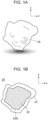
- Fig. 1A is a schematic view illustrating the appearance of each active material particle according to the first embodiment.
- Fig. 1B is a schematic view illustrating a cross section of the active material particle according to the first embodiment.
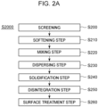
- Fig. 2A is a flowchart illustrating a method for producing active material particles according to the first embodiment.
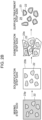
- Fig. 2B is a schematic process diagram illustrating a method for producing active material particles according to the first embodiment.
- Fig. 5A is a schematic cross-sectional view illustrating the layer structure of a secondary battery according to a reference embodiment.
- Fig. 1A is a schematic view illustrating the appearance of each active material particle according to the first embodiment.
- Fig. 1B is a schematic view illustrating a cross section of the active material particle according to the first embodiment.
- Fig. 2A is a flowchart illustrating a method for producing active material particles according to the first embodiment.
- Fig. 2B is a schematic process diagram illustrating a method for producing active material particles according
- FIG. 5B is a schematic cross-sectional view illustrating the layer structure of an anode active material layer according to the reference embodiment.
- Fig. 5C is a flowchart illustrating a method for producing a secondary battery according to the reference embodiment.
- Fig. 5D is a flowchart illustrating a method for producing an anode active material layer according to the reference embodiment.
- each of the active material particles 25 including a protective layer 23 includes a particle portion 22 and the protective layer 23 covering the surface of the particle portion 22.
- the protective layer 23 covers the surface 22S of the particle portion 22 for the purpose of protecting the surface of the particle portion 22 corresponding to a naked active material particle from chemical erosion from the atmosphere and physical damage from the outside, for example.
- the protective layer 23 is disposed on the surface 22S in the form of a continuous film, a discontinuous film, a porous film, a laminated film, or islands.
- the protective layers 23 cover the respective particle portions 22.
- the active material particles 25 of the present embodiment include the protective layer 23 that protects the particle portion 22 for each particle.
- the active material particles 25 of the present embodiment include the protective layer 23 so as to have a particle size that is 1.2 or more times the particle size of the particle portion 22.
- the particle portion 22 may be referred to as a bare active material particle 22, an unprotected active material particle 22, or an active material particle 22 without protection. Since the active material particles 25 cover the surfaces 22S of the particle portions 22, the particle portions 22 containing the active material is protected during a handling period including a process of selling, storing, and transporting the active material particles 25 as a commercial product and a process of storing, depositing, and patterning after purchase. In other words, the active material particles 25 cover the surfaces 22S of the particle portions 22 to protect the surfaces 22S of the particle portions 22 during the handling period of the particle portions 22.
- the protective layer 23 has substantially no viscosity. This reduces the risk of inclusions of, for example, dust and fine particles during the handling period, thereby reducing the risk of contamination of the particle portion 22.
- the low viscosity of the protective layer 23 indicates that the protective layer 23 is solid or the protective layer 23 has no fluidity.
- the fact that the protective layer 23 does not have viscosity not only reduces the risk of contamination of the particle portion 22 during handling, but also ensures flexibility in the arrangement of the active material raw material as the precursor of an anode active material layer 20.
- the fact that the protective layer 23 does not have viscosity reduces the adhesion between the active material raw material and a production apparatus or between the active material raw material and a jig or tool during handling, reducing the number of steps including a cleaning step.
- the viscosity of the protective layer 23 a material having substantially no fluidity in the temperature range of 10°C or higher and 30°C or lower, which corresponds to normal temperature, is selected.
- the protective layer 23 has a viscosity coefficient of 1,000 Pa ⁇ s or less in the temperature range of 10°C or higher and 30°C or lower.
- a viscosity coefficient of 1,000 Pa ⁇ s corresponds to a viscosity coefficient of 1 ⁇ 10 6 cP or less.
- Such a viscosity coefficient is identified as a viscosity coefficient with respect to a shear force or a tensile force.
- the handling period related to the use cases and issues of the unprotected active material particles 22 includes a process of selling, storing, and transporting the naked active material particles 22 as a product, and a process of storing, depositing, and patterning after purchase.
- a process of depositing the unprotected active material particles 22 includes a step S510 of disposing an anode active material layer and a step S540 of disposing a cathode active material layer included in a method S5000 for producing a secondary battery illustrated in Fig. 5C .
- the method S5000 for producing a secondary battery is an example of a method for producing a secondary battery 100, the secondary battery 100 being illustrated in Fig. 5A .
- the step S510 of disposing an anode active material layer further includes a step S515 of disposing active material particles and a step S518 of stacking an anode active material layer, as illustrated in Fig. 5C .
- the step S510 of disposing the anode active material layer is an example of a method for producing the anode active material layer 20 including the sublayers 20a to 20c, the anode active material layer 20 being illustrated in Fig. 5B .
- the anode active material layer 20 may contain an electrolyte, not illustrated in Fig. 5B , in the anode.
- the protective layer 23 further has the property of being selectively removable from the surface 22S while leaving the particle portion 22.
- the selectively removable property is also referred to as selective removability.
- the protective layers 23 have the selective removability for the particle portions 22 and thus protect the particle portions 22 and the surfaces 22S of the particle portions 22 during a handling period from the time of distribution of the active material particles 25 as a commercial product to immediately before the formation of the anode active material layer 20 and a cathode active material layer 50. After the handling period, the protective layers 23 can be selectively removed so as to expose the surfaces 22S of the active material particles 22 constituting the anode active material layer 20 and the cathode active material layer 50 at the stage of transporting active material ions.
- the selective removability for the particle portions 22 includes at least one of erodibility that permits chemical removal, a thermophysical property that permits removal by heating, or a strength property that permits removal by an external force.
- the chemical erodibility includes a mode in which the protective layers 23 over the particle portions 22 are selectively eroded by the use of at least one of a predetermined solvent, a predetermined ion, a predetermined gas, and a predetermined plasma.
- a method of selective removal using the erodibility includes dry etching and wet etching using an etchant having a specifically different etch rate between the particle portion 22 and the protective layer 23.
- the method of selective removal using the thermophysical property includes at least one of a thermal decomposition reaction, a phase transition, or combustion.
- the method of selective removal using a difference in strength property includes at least one of milling, buffing, or blasting of particles.
- a method for producing the active material particles 25 having the protective layers 23 according to the first embodiment will be described with reference to Figs. 2A and 2B .
- a method S2000 for producing the active material particles 25 of the present embodiment includes a screening step S200, a softening step S210, a mixing step S220, a dispersion step S230, a solidification step S240, a disintegration step S250, and a surface treatment step S260, these steps being performed in this order.
- the screening step S200 screens the unprotected active material particles 22.
- the softening step S210 softens the protective material to be formed into the protective layers 40 by heating.
- the softening step S210 for the protective material ensures fluidity of the protective material in the mixing step S220 and the dispersion step S230.
- the mixing step S220 mixes the unprotected active material particles 22 and the softened protective layer material 23p.
- the dispersion step S230 disperses the unprotected active material particles 22 contained in the mixture. This step ensures the particle size ratio (diameter ratio) of each of the protective layers 23 to a corresponding one of the particle portions 22.
- the disintegration step S250 includes a step of disintegrating the particle portions 22 fixed to the protective layer 23b solidified in a bulk form into individual particle units.
- the disintegration step S230 can be performed by ball milling.
- the particle portions 22 protected by the protective layers 23S separated for each particle are obtained by the disintegration step S240.
- the separated protective layers 23S obtained in this step can be regarded as the self-supporting active material particles 25 including the particle portions 22b protected by the self-supporting protective layers 23S.
- the softened protective layer material 23p may be referred to as the precursor 23p of the protective layer 23.
- the surface treatment step S260 includes a step of grinding protruding portions and so forth on the surfaces of the protective layers 23S, i.e., on the surfaces of the self-supporting active material particles 22 including the protective layers 23S and the particle portions 22b in order to ensure the flexibility in disposing the active material particles 22.
- the configuration of the active material particles 25 according to a second embodiment will be described below with reference to Figs. 3A and 3B .
- the active material particles 25 of the present embodiment are different from the active material particles 25 according to the first embodiment in that the protective layer 23 integrally protects the multiple particle portions 22 as illustrated in Fig. 3B .
- the protective layer 23 has a layer thickness t and extends in the directions (x direction, y direction), intersecting the direction (z direction) of the layer thickness, by distances d and W larger than the layer thickness t, thereby protecting the multiple particle portions 22.
- the protective layer 23 or the active material particle 25 of the present embodiment has a sheet-like shape.
- a layer including the active material particles extending in a sheet shape can be formed by disposing the sheet-like active material particle 25 and then removing the protective layer 23. That is, the sheet-like active material particle 25 of the present embodiment can be regarded as the precursor of the anode active material layer 20 because the particle portions 22 containing the active material are arranged in the layer direction.
- the sheet-like protective layer 23 of the present embodiment covers the multiple surfaces 22 corresponding to the multiple particle portions 22.
- the configuration of the active material particle 25 according to a third embodiment will be described below with reference to Fig. 3C .
- the protective layer 23 of the active material particle 25 of the present embodiment is different from the active material particle 25 of the second embodiment in that the particle portions 22 are arranged in a predetermined pattern and that grooves are provided in a lattice pattern between regions where the particle portions 22 are arranged.
- the active material particle 25 of the present embodiment is cut along the lattice-like grooves to obtain the active material particles 25 of the first embodiment in which each particle portion is protected.
- a bending force is applied to the active material particle 25 of the present embodiment in such a manner that the stress is concentrated along the lattice-like grooves, thereby providing the active material particles 25 of the first embodiment in which each particle portion is protected.
- the configuration of the active material particle 25 according to a fourth embodiment will be described below with reference to Fig. 3D .
- the protective layer 23 included in the active material particle 25 of the present embodiment differs from the active material particle 25 of the second and third embodiments in that it has a bulk-like general shape.
- a method S4000 for producing active material particles of a first modification differs from the method S2000 for producing the active material particles in that it includes a solution preparation step S410 and a drying step S440, as illustrated in Fig. 4A , instead of the softening step S210 and the solidification step S240.
- the solution preparation step S410 is a step of dissolving a powder raw material serving as the precursor of the protective layer 23 in a solvent to prepare a solution.
- the solution preparation step S410 can be modified to a step of preparing a dispersion by micellization of the powder raw material serving as a precursor.
- the drying step S440 is a step of evaporating the solvent from the solution to form a protective layer protecting the surfaces 22S of the active material particles 22 (particle portions 22) that are solid components.
- a method S4200 for producing active material particles of a second modification differs from the production method S2000 in that it includes a spraying step S470 for spraying the protective material and the particle portions and preparation steps S460 and S465 thereof and that it does not include the disintegration step S450.
- the spraying step S460 and the drying step S440 may be performed simultaneously.
- the aerosol is easily dried due to its large specific surface area (S/V), and the active material particles 25 separated into individual particles are formed.
- the disintegration step S440 is not necessarily required.
- a method S4400 for producing active material particles of a third modification differs from the production method S2000 in a precursor mixing step S425 of mixing the precursor of the protective material and the particle portions 22 and the synthesis step S480 of synthesizing the protective material constituting the protective layer.
- the production method S4400 also differs from the production method S2000 in that a rinsing step S490 is provided.
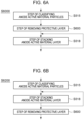
- a method S6000 for producing an anode active material layer with the active material particles 25 according to the first embodiment will be described below with reference to Fig. 6A .
- the production method S6000 of the present embodiment differs from the process S510 of disposing the anode active material layer of the reference embodiment in that a step S600 of removing the protective layer is provided after the step S518 of stacking the anode active material layer.
- the production method S6200 of the present embodiment differs from the process S510 of disposing the anode active material layer of the reference embodiment in that the step S600 of removing the protective layer is provided between a step S515 of classifying the anode active material particles and the step S518 of stacking the anode active material layer.
- the particle portions 22 containing the active material are protected by the protective layers 23 during the handling period until at least immediately before the stacking step S518 corresponding to a step of disposing the active material particles.
- a transition metal oxide or a transition metal composite oxide is used as the anode active material contained in the particle portion 22 as the anode active material contained in the particle portion 22 .
- olivine type LiMbPO4 (where Mb is one or more elements selected from Co, Ni, Mn, Fe, Mg, Nb, Ti, Al, and Zr) or lithium vanadium phosphate (Li3V2(PO4)3 or LiVOPO4) is used.
- LisNitCouAlvO2 (0.9 ⁇ s ⁇ 1.3, 0.9 ⁇ t + u + v ⁇ 1.1) corresponds to a composite metal oxide.
- An oxide containing Li and Co is used as the active material, as described above.
- the particle size of the active material particles 22 refers to the cumulative 50% particle size (median diameter) on a volume basis.
- the particle size of the active material particles 22 can be measured with a laser diffraction/scattering particle size distribution analyzer (LA-960, available from Horiba, Ltd).
- the particle size of the particle portion 22 containing the anode active material can be 0.1 ⁇ m or more and 100 pm or less.
- the cathode active material examples include metals, metal fibers, carbon materials, oxides, nitrides, silicon, silicon compounds, tin, tin compounds, and various alloy materials.
- the cathode active material is preferably, for example, a metal, an oxide, a carbon material, silicon, a silicon compound, tin, or a tin compound, from the viewpoint of capacity density.
- a metal used for the cathode active material include metal Li and In-Li, and an example of an oxide is Li4Ti5O12 (lithium titanate: LTO).
- a carbon material used for the cathode active material is selected from graphite allotropes having conductivity other than diamond.
- the carbon material includes natural graphite (graphite), coke, a graphitizable carbon material undergoing graphitization, carbon fiber, spherical carbon, various artificial graphites, amorphous carbon, and so forth.
- Examples of a silicon compound used for the cathode active material include silicon-containing alloys, silicon-containing inorganic compounds, silicon-containing organic compounds, and solid solutions.
- Examples of a tin compound used for the cathode active material include SnOb (0 ⁇ b ⁇ 2), SnO2, SnSiO3, Ni2Sn4, and Mg2Sn.
- the cathode active material layer may contain a conductive aid together with the cathode active material.
- the conductive aid include graphites, such as natural graphite and artificial graphite, and carbon blacks, such as acetylene black, ketjen black, channel black, furnace black, lamp black, and thermal black.
- Other examples of the conductive aid include conductive fibers, such as carbon fibers, carbon nanotubes, and metal fibers, carbon fluoride, metal powders, such as aluminum, conductive metal oxides, such as conductive whiskers, e.g., zinc oxide, and titanium oxide, and organic conductive materials, such as phenylene dielectrics.
- the protective material used for the protective layer 23 a material having the effect of protecting the particle portion 22 as described above and the effect of being selectively removed with respect to the particle portion 22 is selected.
- the protective material may be an inorganic material or an organic material.
- organic materials used for the protective layer 23 include polyester, polypropylene, sugar, styrene resins, acrylic resins, urethane resins, vinyl acetate resins, poly(vinyl alcohol) resins, poly(vinyl acetal) resins, and poly(vinyl butyral) resins.
- Further examples of organic materials used for the protective layer 23 include terpineol resins and ethyl cellulose resins.
- the protective layer 23 is preferably contained in a large excess.
- the ratio by weight of the protective layer 23 to the particle portion 22 can be 20% or more.
Landscapes
- Chemical & Material Sciences (AREA)
- Chemical Kinetics & Catalysis (AREA)
- Electrochemistry (AREA)
- General Chemical & Material Sciences (AREA)
- Composite Materials (AREA)
- Battery Electrode And Active Subsutance (AREA)
Abstract
Description
- The present invention relates to active material particles and a method for producing active material particles.
- An electrode structure for a secondary battery has been known in which a change in the volume of an active material due to the intercalation and deintercalation of lithium ions is reduced by providing fine protruding portions.
Japanese Patent Laid-Open No. 2015-220080 - It is known that when a secondary battery is produced, the charge-discharge characteristics are improved by allowing an active material layer to have a two-dimensional or three-dimensional distribution of the characteristics, composition, and the like or by devising arrangement in the layer or in the thickness direction in accordance with a current collector and an electrolyte combined.
Japanese Patent Laid-Open No. 2012-104270 -
- PTL 1:
Japanese Patent Laid-Open No. 2015-220080 - PTL 2:
Japanese Patent Laid-Open No. 2012-104270 - The active material particles having a surface structure ensuring ionic conductivity obtained by the method described in
Japanese Patent Laid-Open No. 2015-220080 Japanese Patent Laid-Open No. 2015-220080 - It is conceivable that active material particles having a surface structure ensuring ionic conductivity may be produced by separating an active material having a surface structure ensuring ionic conductivity, which is produced by the method described in
Japanese Patent Laid-Open No. 2015-220080 - Even if the active material particles having a surface structure ensuring ionic conductivity produced by the method described in
Japanese Patent Laid-Open No. 2015-220080 - It is an object of the present application to provide a self-supporting active material with reduced risk of quality degradation due to handling.
- Active material particles according to an embodiment of the present invention are active material particles for use in an active material layer and include self-supporting active material particles that include a particle portion containing an active material and that a protective layer covering the surface of the particle portion.
- With respect to active material particles according to an embodiment of the present invention, the active material particles according to Claim 1, for use in the active material layer, in which the protective layer is solid, include a particle portion containing an active material and the solid protective layer covering the surface of the particle portion.
- According to the present invention, it is possible to provide a self-supporting active material with reduced risk of quality deterioration due to handling.
-
- [
Fig. 1A] Fig. 1A is a schematic view illustrating the appearance of an active material particle according to a first embodiment. - [
Fig. 1B] Fig. 1B is a schematic view illustrating a cross section of an active material particle according to the first embodiment. - [
Fig. 2A] Fig. 2A is a flowchart illustrating a method for producing active material particles according to the first embodiment. - [
Fig. 2B] Fig. 2B is a schematic process diagram illustrating a method for producing active material particles according to the first embodiment. - [
Fig. 3A] Fig. 3A illustrates the appearance of active material particles according to a second embodiment. - [
Fig. 3B] Fig. 3B illustrates a cross section of active material particles according to the second embodiment. - [
Fig. 3C] Fig. 3C illustrates a cross section of active material particles according to third and fourth embodiments. - [
Fig. 3D] Fig. 3D illustrates a cross section of active material particles according to the third and fourth embodiments. - [
Fig. 4A] Fig. 4A is a flowchart illustrating an example of a method for producing active material particles according to a first modification of the first embodiment. - [
Fig. 4B] Fig. 4B is a flowchart illustrating an example of a method for producing active material particles according to a second modification of the first embodiment. - [
Fig. 4C] Fig. 4C is a flowchart illustrating an example of a method for producing active material particles according to a third modification of the first embodiment. - [
Fig. 5A] Fig. 5A is a schematic cross-sectional view illustrating the layer structure of a secondary battery according to a reference embodiment. - [
Fig. 5B] Fig. 5B is a schematic cross-sectional view illustrating the layer structure of an anode active material layer according to a reference embodiment. - [
Fig. 5C] Fig. 5C is a flowchart illustrating a method for producing a secondary battery according to a reference embodiment. - [
Fig. 5D] Fig. 5D is a flowchart illustrating a method for producing an anode active material layer according to a reference embodiment. - [
Fig. 6A] Fig. 6A is a flowchart illustrating a method for producing an anode active material layer according to fifth and sixth embodiments. - [
Fig. 6B] Fig. 6B is a flowchart illustrating a method for producing an anode active material layer according to the fifth and sixth embodiments. - Preferred embodiments of the present invention are described in detail below with reference to the drawings. Dimensions, materials, shapes, relative arrangements, and the like of constituent members described in these embodiments are not intended to limit the scope of the present invention.
- The structure and production method of
active material particles 25 according to a first embodiment will be described with reference toFigs. 1A, 1B ,2A ,2B ,5A, and 5B .Fig. 1A is a schematic view illustrating the appearance of each active material particle according to the first embodiment.Fig. 1B is a schematic view illustrating a cross section of the active material particle according to the first embodiment.Fig. 2A is a flowchart illustrating a method for producing active material particles according to the first embodiment.Fig. 2B is a schematic process diagram illustrating a method for producing active material particles according to the first embodiment.Fig. 5A is a schematic cross-sectional view illustrating the layer structure of a secondary battery according to a reference embodiment.Fig. 5B is a schematic cross-sectional view illustrating the layer structure of an anode active material layer according to the reference embodiment.Fig. 5C is a flowchart illustrating a method for producing a secondary battery according to the reference embodiment.Fig. 5D is a flowchart illustrating a method for producing an anode active material layer according to the reference embodiment. - The structure of each of the
active material particles 25 including aprotective layer 23 according to the first embodiment will be described with reference toFigs. 1A and 1B . Each of theactive material particles 25 of the present embodiment includes aparticle portion 22 and theprotective layer 23 covering the surface of theparticle portion 22. Theprotective layer 23 covers thesurface 22S of theparticle portion 22 for the purpose of protecting the surface of theparticle portion 22 corresponding to a naked active material particle from chemical erosion from the atmosphere and physical damage from the outside, for example. In the range of the protection purpose described above, theprotective layer 23 is disposed on thesurface 22S in the form of a continuous film, a discontinuous film, a porous film, a laminated film, or islands. In other words, theprotective layers 23 cover therespective particle portions 22. Theactive material particles 25 of the present embodiment include theprotective layer 23 that protects theparticle portion 22 for each particle. Theactive material particles 25 of the present embodiment include theprotective layer 23 so as to have a particle size that is 1.2 or more times the particle size of theparticle portion 22. - In the specification of the present application, the
particle portion 22 may be referred to as a bareactive material particle 22, an unprotectedactive material particle 22, or anactive material particle 22 without protection. Since theactive material particles 25 cover thesurfaces 22S of theparticle portions 22, theparticle portions 22 containing the active material is protected during a handling period including a process of selling, storing, and transporting theactive material particles 25 as a commercial product and a process of storing, depositing, and patterning after purchase. In other words, theactive material particles 25 cover thesurfaces 22S of theparticle portions 22 to protect thesurfaces 22S of theparticle portions 22 during the handling period of theparticle portions 22. - The
protective layer 23 has substantially no viscosity. This reduces the risk of inclusions of, for example, dust and fine particles during the handling period, thereby reducing the risk of contamination of theparticle portion 22. - The low viscosity of the
protective layer 23 indicates that theprotective layer 23 is solid or theprotective layer 23 has no fluidity. The fact that theprotective layer 23 does not have viscosity not only reduces the risk of contamination of theparticle portion 22 during handling, but also ensures flexibility in the arrangement of the active material raw material as the precursor of an anodeactive material layer 20. The fact that theprotective layer 23 does not have viscosity reduces the adhesion between the active material raw material and a production apparatus or between the active material raw material and a jig or tool during handling, reducing the number of steps including a cleaning step. - For the viscosity of the
protective layer 23, a material having substantially no fluidity in the temperature range of 10°C or higher and 30°C or lower, which corresponds to normal temperature, is selected. Theprotective layer 23 has a viscosity coefficient of 1,000 Pa·s or less in the temperature range of 10°C or higher and 30°C or lower. A viscosity coefficient of 1,000 Pa·s corresponds to a viscosity coefficient of 1 × 10⁶ cP or less. Such a viscosity coefficient is identified as a viscosity coefficient with respect to a shear force or a tensile force. - The handling period related to the use cases and issues of the unprotected
active material particles 22 includes a process of selling, storing, and transporting the nakedactive material particles 22 as a product, and a process of storing, depositing, and patterning after purchase. A process of depositing the unprotectedactive material particles 22 includes a step S510 of disposing an anode active material layer and a step S540 of disposing a cathode active material layer included in a method S5000 for producing a secondary battery illustrated inFig. 5C . The method S5000 for producing a secondary battery is an example of a method for producing asecondary battery 100, thesecondary battery 100 being illustrated inFig. 5A . - The step S510 of disposing an anode active material layer further includes a step S515 of disposing active material particles and a step S518 of stacking an anode active material layer, as illustrated in
Fig. 5C . The step S510 of disposing the anode active material layer is an example of a method for producing the anodeactive material layer 20 including thesublayers 20a to 20c, the anodeactive material layer 20 being illustrated inFig. 5B . The anodeactive material layer 20 may contain an electrolyte, not illustrated inFig. 5B , in the anode. - The
protective layer 23 further has the property of being selectively removable from thesurface 22S while leaving theparticle portion 22. The selectively removable property is also referred to as selective removability. The protective layers 23 have the selective removability for theparticle portions 22 and thus protect theparticle portions 22 and thesurfaces 22S of theparticle portions 22 during a handling period from the time of distribution of theactive material particles 25 as a commercial product to immediately before the formation of the anodeactive material layer 20 and a cathodeactive material layer 50. After the handling period, theprotective layers 23 can be selectively removed so as to expose thesurfaces 22S of theactive material particles 22 constituting the anodeactive material layer 20 and the cathodeactive material layer 50 at the stage of transporting active material ions. - The selective removability for the
particle portions 22 includes at least one of erodibility that permits chemical removal, a thermophysical property that permits removal by heating, or a strength property that permits removal by an external force. - The chemical erodibility includes a mode in which the
protective layers 23 over theparticle portions 22 are selectively eroded by the use of at least one of a predetermined solvent, a predetermined ion, a predetermined gas, and a predetermined plasma. A method of selective removal using the erodibility includes dry etching and wet etching using an etchant having a specifically different etch rate between theparticle portion 22 and theprotective layer 23. - The method of selective removal using the thermophysical property includes at least one of a thermal decomposition reaction, a phase transition, or combustion. The method of selective removal using a difference in strength property includes at least one of milling, buffing, or blasting of particles.
- A method for producing the
active material particles 25 having theprotective layers 23 according to the first embodiment will be described with reference toFigs. 2A and2B . A method S2000 for producing theactive material particles 25 of the present embodiment includes a screening step S200, a softening step S210, a mixing step S220, a dispersion step S230, a solidification step S240, a disintegration step S250, and a surface treatment step S260, these steps being performed in this order. - The screening step S200 screens the unprotected
active material particles 22. The softening step S210 softens the protective material to be formed into theprotective layers 40 by heating. The softening step S210 for the protective material ensures fluidity of the protective material in the mixing step S220 and the dispersion step S230. The mixing step S220 mixes the unprotectedactive material particles 22 and the softenedprotective layer material 23p. The dispersion step S230 disperses the unprotectedactive material particles 22 contained in the mixture. This step ensures the particle size ratio (diameter ratio) of each of theprotective layers 23 to a corresponding one of theparticle portions 22. - In the solidification step S240, the fluidity of the
protective layer material 23p is lost by cooling to obtain theprotective layer 23b solidified in a bulk form and theparticle portions 22 fixed to theprotective layer 23b. The disintegration step S250 includes a step of disintegrating theparticle portions 22 fixed to theprotective layer 23b solidified in a bulk form into individual particle units. The disintegration step S230 can be performed by ball milling. Theparticle portions 22 protected by the protective layers 23S separated for each particle are obtained by the disintegration step S240. The separated protective layers 23S obtained in this step can be regarded as the self-supportingactive material particles 25 including the particle portions 22b protected by the self-supporting protective layers 23S. The softenedprotective layer material 23p may be referred to as theprecursor 23p of theprotective layer 23. - The surface treatment step S260 includes a step of grinding protruding portions and so forth on the surfaces of the protective layers 23S, i.e., on the surfaces of the self-supporting
active material particles 22 including the protective layers 23S and the particle portions 22b in order to ensure the flexibility in disposing theactive material particles 22. - The configuration of the
active material particles 25 according to a second embodiment will be described below with reference toFigs. 3A and 3B . Theactive material particles 25 of the present embodiment are different from theactive material particles 25 according to the first embodiment in that theprotective layer 23 integrally protects themultiple particle portions 22 as illustrated inFig. 3B . As illustrated inFig. 3A , theprotective layer 23 has a layer thickness t and extends in the directions (x direction, y direction), intersecting the direction (z direction) of the layer thickness, by distances d and W larger than the layer thickness t, thereby protecting themultiple particle portions 22. In other words, theprotective layer 23 or theactive material particle 25 of the present embodiment has a sheet-like shape. In the sheet-likeactive material particle 25 of the embodiment, a layer including the active material particles extending in a sheet shape can be formed by disposing the sheet-likeactive material particle 25 and then removing theprotective layer 23. That is, the sheet-likeactive material particle 25 of the present embodiment can be regarded as the precursor of the anodeactive material layer 20 because theparticle portions 22 containing the active material are arranged in the layer direction. The sheet-likeprotective layer 23 of the present embodiment covers themultiple surfaces 22 corresponding to themultiple particle portions 22. - The configuration of the
active material particle 25 according to a third embodiment will be described below with reference toFig. 3C . Theprotective layer 23 of theactive material particle 25 of the present embodiment is different from theactive material particle 25 of the second embodiment in that theparticle portions 22 are arranged in a predetermined pattern and that grooves are provided in a lattice pattern between regions where theparticle portions 22 are arranged. Theactive material particle 25 of the present embodiment is cut along the lattice-like grooves to obtain theactive material particles 25 of the first embodiment in which each particle portion is protected. In addition, a bending force is applied to theactive material particle 25 of the present embodiment in such a manner that the stress is concentrated along the lattice-like grooves, thereby providing theactive material particles 25 of the first embodiment in which each particle portion is protected. - The configuration of the
active material particle 25 according to a fourth embodiment will be described below with reference toFig. 3D . Theprotective layer 23 included in theactive material particle 25 of the present embodiment differs from theactive material particle 25 of the second and third embodiments in that it has a bulk-like general shape. - Modifications of the method S2000 for producing the active material particles according to the first embodiment will be described below with reference to
Figs. 4A, 4B, and 4C . - A method S4000 for producing active material particles of a first modification differs from the method S2000 for producing the active material particles in that it includes a solution preparation step S410 and a drying step S440, as illustrated in
Fig. 4A , instead of the softening step S210 and the solidification step S240. - The solution preparation step S410 is a step of dissolving a powder raw material serving as the precursor of the
protective layer 23 in a solvent to prepare a solution. The solution preparation step S410 can be modified to a step of preparing a dispersion by micellization of the powder raw material serving as a precursor. - The drying step S440 is a step of evaporating the solvent from the solution to form a protective layer protecting the
surfaces 22S of the active material particles 22 (particle portions 22) that are solid components. - As illustrated in
Fig. 4B , a method S4200 for producing active material particles of a second modification differs from the production method S2000 in that it includes a spraying step S470 for spraying the protective material and the particle portions and preparation steps S460 and S465 thereof and that it does not include the disintegration step S450. - The spraying step S460 and the drying step S440 may be performed simultaneously. In a process of coating the
particle portions 22 with the solution containing the protective material, the aerosol is easily dried due to its large specific surface area (S/V), and theactive material particles 25 separated into individual particles are formed. Thus, the disintegration step S440 is not necessarily required. - As illustrated in
Fig. 4C , a method S4400 for producing active material particles of a third modification differs from the production method S2000 in a precursor mixing step S425 of mixing the precursor of the protective material and theparticle portions 22 and the synthesis step S480 of synthesizing the protective material constituting the protective layer. The production method S4400 also differs from the production method S2000 in that a rinsing step S490 is provided. - A method S6000 for producing an anode active material layer with the
active material particles 25 according to the first embodiment will be described below with reference toFig. 6A . The production method S6000 of the present embodiment differs from the process S510 of disposing the anode active material layer of the reference embodiment in that a step S600 of removing the protective layer is provided after the step S518 of stacking the anode active material layer. - Another method S6200 for producing an anode active material layer with the
active material particles 25 according to the first embodiment will be described below with reference toFig. 6B . The production method S6200 of the present embodiment differs from the process S510 of disposing the anode active material layer of the reference embodiment in that the step S600 of removing the protective layer is provided between a step S515 of classifying the anode active material particles and the step S518 of stacking the anode active material layer. - According to the production methods of the anode active material layer S6000 and S6200 according to the fifth and sixth embodiments, the
particle portions 22 containing the active material are protected by theprotective layers 23 during the handling period until at least immediately before the stacking step S518 corresponding to a step of disposing the active material particles. - Materials forming the
active material particles 25 according to the first to fourth embodiments will be described below. - As the anode active material contained in the
particle portion 22, a transition metal oxide or a transition metal composite oxide is used. - Lithium-manganese composite oxide Li2MnaMa1-aO3 (0.8 ≤ a ≤ 1, Ma = Co, Ni), lithium cobaltate (LiCoO2), lithium nickelate (LiNiO2), or lithium-manganese spinel (LiMn2O4) is used as the anode active material. As the anode active material, a composite metal oxide represented by general formula: LiNixCoyMnzO2 (x + y + z = 1, 0 ≤ x ≤ 1, 0 ≤ y ≤ 1, 0 ≤ z ≤ 1) or a lithium vanadium compound (LiV2O5) is used. As the anode active material, olivine type LiMbPO4 (where Mb is one or more elements selected from Co, Ni, Mn, Fe, Mg, Nb, Ti, Al, and Zr) or lithium vanadium phosphate (Li3V2(PO4)3 or LiVOPO4) is used. As the anode active material, a Li-rich solid solution represented by Li2MnO3-LiMcO2 (Mc = Mn, Co, Ni), lithium titanate (Li4Ti5O12), or LisNitCouAlvO2 (0.9 < s < 1.3, 0.9 < t + u + v < 1.1) is used. LisNitCouAlvO2 (0.9 < s < 1.3, 0.9 < t + u + v < 1.1) corresponds to a composite metal oxide.
- An oxide containing Li and Co is used as the active material, as described above.
- In the specification of the present application, when the particle size of the
active material particles 22 is described, the particle size refers to the cumulative 50% particle size (median diameter) on a volume basis. The particle size of theactive material particles 22 can be measured with a laser diffraction/scattering particle size distribution analyzer (LA-960, available from Horiba, Ltd). - The particle size of the
particle portion 22 containing the anode active material can be 0.1 µm or more and 100 pm or less. - Examples of the cathode active material include metals, metal fibers, carbon materials, oxides, nitrides, silicon, silicon compounds, tin, tin compounds, and various alloy materials. The cathode active material is preferably, for example, a metal, an oxide, a carbon material, silicon, a silicon compound, tin, or a tin compound, from the viewpoint of capacity density. Examples of a metal used for the cathode active material include metal Li and In-Li, and an example of an oxide is Li4Ti5O12 (lithium titanate: LTO).
- A carbon material used for the cathode active material is selected from graphite allotropes having conductivity other than diamond. The carbon material includes natural graphite (graphite), coke, a graphitizable carbon material undergoing graphitization, carbon fiber, spherical carbon, various artificial graphites, amorphous carbon, and so forth. Examples of a silicon compound used for the cathode active material include silicon-containing alloys, silicon-containing inorganic compounds, silicon-containing organic compounds, and solid solutions. Examples of a tin compound used for the cathode active material include SnOb (0 < b < 2), SnO2, SnSiO3, Ni2Sn4, and Mg2Sn.
- The cathode active material layer may contain a conductive aid together with the cathode active material. Examples of the conductive aid include graphites, such as natural graphite and artificial graphite, and carbon blacks, such as acetylene black, ketjen black, channel black, furnace black, lamp black, and thermal black. Other examples of the conductive aid include conductive fibers, such as carbon fibers, carbon nanotubes, and metal fibers, carbon fluoride, metal powders, such as aluminum, conductive metal oxides, such as conductive whiskers, e.g., zinc oxide, and titanium oxide, and organic conductive materials, such as phenylene dielectrics.
- As the protective material used for the
protective layer 23, a material having the effect of protecting theparticle portion 22 as described above and the effect of being selectively removed with respect to theparticle portion 22 is selected. The protective material may be an inorganic material or an organic material. Examples of organic materials used for theprotective layer 23 include polyester, polypropylene, sugar, styrene resins, acrylic resins, urethane resins, vinyl acetate resins, poly(vinyl alcohol) resins, poly(vinyl acetal) resins, and poly(vinyl butyral) resins. Further examples of organic materials used for theprotective layer 23 include terpineol resins and ethyl cellulose resins. - From the viewpoint of protecting the
particle portion 22 from chemical corrosion and external force, theprotective layer 23 is preferably contained in a large excess. The ratio by weight of theprotective layer 23 to theparticle portion 22 can be 20% or more. - The present invention is not limited to the above-described embodiments, and various changes and modifications can be made without departing from the spirit and scope of the present invention. Therefore, the following claims are attached in order to make the scope of the present invention public.
- This application claims priority based on
Japanese Patent Application No. 2020-209077 filed on December 17, 2020
Claims (15)
- Self-supporting active material particles for use in an active material layer, comprising a particle portion containing an active material, and a protective layer covering a surface of the particle portion.
- The active material particles according to Claim 1, wherein the protective layer is solid.
- Active material particles for use in an active material layer, comprising a particle portion containing an active material, and a solid protective layer covering a surface of the particle portion.
- The active material particles according to any one of Claims 1 to 3, wherein the active material contains an anode active material or a cathode active material.
- The active material particles according to any one of Claims 1 to 4, wherein the protective layer has no fluidity in a temperature range of 10°C or higher and 30°C or lower.
- The active material particles according to any one of Claims 1 to 5, wherein the protective layer has a viscosity coefficient of 1,000 Pa·s or less in a temperature range of 10°C or higher and 30°C or lower.
- The active material particles according to any one of Claims 1 to 6, wherein the protective layer covers the particle portion for each particle portion.
- The active material particles according to Claim 7, wherein the active material particles have a particle size that is 1.2 or more times larger than the particle size of the particle portion.
- The active material particles according to any one of Claims 1 to 8, wherein the protective layer covers the surfaces corresponding to the multiple particle portions.
- The active material particles according to any one of Claims 1 to 9, wherein the protective layer has a sheet-like shape having a layer thickness and extending in a direction intersecting the layer thickness by a distance larger than the layer thickness.
- The active material particles according to any one of Claims 1 to 10, wherein the protective layer has a property of being selectively removable from the surface while leaving the particle portion.
- The active material particles according to Claim 11, wherein the property includes an erodibility that permits chemical removal.
- The active material particles according to Claim 11, wherein the property includes a thermophysical property that permits removal by heating.
- The active material particles of Claim 11, wherein the property includes a strength property that permits removal by an external force.
- The active material particles according to any one of Claims 1 to 14, wherein the protective layer continuously covers the surface.
Applications Claiming Priority (2)
| Application Number | Priority Date | Filing Date | Title |
|---|---|---|---|
| JP2020209077A JP2022096142A (en) | 2020-12-17 | 2020-12-17 | Active material particles and manufacturing method of active material particles |
| PCT/JP2021/046047 WO2022131250A1 (en) | 2020-12-17 | 2021-12-14 | Active material particles and method for producing active material particles |
Publications (1)
| Publication Number | Publication Date |
|---|---|
| EP4266403A1 true EP4266403A1 (en) | 2023-10-25 |
Family
ID=82059477
Family Applications (1)
| Application Number | Title | Priority Date | Filing Date |
|---|---|---|---|
| EP21906612.3A Withdrawn EP4266403A1 (en) | 2020-12-17 | 2021-12-14 | Active material particles and method for producing active material particles |
Country Status (5)
| Country | Link |
|---|---|
| US (1) | US20230327128A1 (en) |
| EP (1) | EP4266403A1 (en) |
| JP (1) | JP2022096142A (en) |
| CN (1) | CN116601791A (en) |
| WO (1) | WO2022131250A1 (en) |
Family Cites Families (10)
| Publication number | Priority date | Publication date | Assignee | Title |
|---|---|---|---|---|
| JP5433276B2 (en) * | 2009-03-30 | 2014-03-05 | Fdk株式会社 | Method for producing lithium composite compound |
| US20130059209A1 (en) * | 2010-05-17 | 2013-03-07 | Sumitomo Electric Industries, Ltd. | Positive-electrode body for nonaqueous-electrolyte battery, method for producing the positive-electrode body, and nonaqueous-electrolyte battery |
| CN102479952B (en) * | 2010-11-23 | 2014-10-08 | 清华大学 | Lithium ion battery electrode composite material and preparation method and battery thereof |
| JP5413355B2 (en) | 2010-11-08 | 2014-02-12 | トヨタ自動車株式会社 | All solid battery |
| JP6228890B2 (en) | 2014-05-16 | 2017-11-08 | 新光電気工業株式会社 | Electrode body and method for producing electrode body |
| JP6111453B2 (en) * | 2015-02-26 | 2017-04-12 | 株式会社アイ.エス.テイ | Polyimide coating active material particles, slurry for electrode material, negative electrode, battery, and method for producing polyimide coating active material particles |
| US10290864B2 (en) * | 2016-04-07 | 2019-05-14 | StoreDot Ltd. | Coated pre-lithiated anode material particles and cross-linked polymer coatings |
| US10483533B2 (en) * | 2017-04-10 | 2019-11-19 | Global Graphene Group, Inc. | Encapsulated cathode active material particles, lithium secondary batteries containing same, and method of manufacturing |
| JP7051312B2 (en) * | 2017-06-14 | 2022-04-11 | 三星エスディアイ株式会社 | Manufacturing method of positive electrode active material, non-aqueous secondary battery, and positive electrode active material |
| KR102754047B1 (en) * | 2018-10-25 | 2025-01-15 | 삼성에스디아이 주식회사 | Composite cathode active material, cathode and lithium battery containing composite cathode active material, and preparation method thereof |
-
2020
- 2020-12-17 JP JP2020209077A patent/JP2022096142A/en active Pending
-
2021
- 2021-12-14 WO PCT/JP2021/046047 patent/WO2022131250A1/en not_active Ceased
- 2021-12-14 CN CN202180084514.8A patent/CN116601791A/en active Pending
- 2021-12-14 EP EP21906612.3A patent/EP4266403A1/en not_active Withdrawn
-
2023
- 2023-06-13 US US18/334,008 patent/US20230327128A1/en active Pending
Also Published As
| Publication number | Publication date |
|---|---|
| JP2022096142A (en) | 2022-06-29 |
| US20230327128A1 (en) | 2023-10-12 |
| WO2022131250A1 (en) | 2022-06-23 |
| CN116601791A (en) | 2023-08-15 |
Similar Documents
| Publication | Publication Date | Title |
|---|---|---|
| JP5480451B2 (en) | Porous electrode active material | |
| US20180069234A1 (en) | Electroactive materials for metal-ion batteries | |
| EP3231027B1 (en) | Electrodes for metal-ion batteries | |
| KR101920806B1 (en) | Composite active material for lithium secondary batteries and method for producing same | |
| JP6116138B2 (en) | Negative electrode active material and secondary battery including the same | |
| JP2017531276A (en) | Electroactive materials for metal ion batteries | |
| KR20160137518A (en) | Negative electrode active material for lithium ion secondary battery, and method for producing same | |
| KR101711525B1 (en) | Positive electrode active material | |
| JP6894243B2 (en) | Negative electrode layer and lithium all-solid-state battery | |
| JP7056598B2 (en) | Negative electrode layer and all-solid-state battery | |
| KR102564614B1 (en) | All solid state battery | |
| JP6092741B2 (en) | Electrode body manufacturing method and electrode body | |
| KR20210151690A (en) | Active material, battery, and methods for producing these | |
| CN116918106A (en) | Cathode materials, electrochemical devices and electronic equipment | |
| EP4012799A1 (en) | All solid state battery | |
| JP7400532B2 (en) | Composite carbon material and its manufacturing method, negative electrode active material for lithium ion secondary batteries, and lithium ion secondary batteries | |
| EP4266403A1 (en) | Active material particles and method for producing active material particles | |
| JP2008166142A (en) | ELECTRODE FOR LITHIUM ION SECONDARY BATTERY, LITHIUM ION SECONDARY BATTERY, AND METHOD FOR PRODUCING ELECTRODE FOR LITHIUM ION SECONDARY BATTERY | |
| KR102924446B1 (en) | Electrode active material, electrode mixture, electrode layer, battery, and method for producing these | |
| KR20260017967A (en) | Electrode layer and battery | |
| KR20260017966A (en) | Electrode layer and battery | |
| KR20260017943A (en) | Electrode layer and battery | |
| KR20260017965A (en) | Electrode layer and battery | |
| EP4510228A1 (en) | Anode active material, anode, and secondary battery comprising same | |
| CN119627082A (en) | A mechanical fusion coated lithium ion battery negative electrode material and preparation method thereof |
Legal Events
| Date | Code | Title | Description |
|---|---|---|---|
| STAA | Information on the status of an ep patent application or granted ep patent |
Free format text: STATUS: THE INTERNATIONAL PUBLICATION HAS BEEN MADE |
|
| PUAI | Public reference made under article 153(3) epc to a published international application that has entered the european phase |
Free format text: ORIGINAL CODE: 0009012 |
|
| STAA | Information on the status of an ep patent application or granted ep patent |
Free format text: STATUS: REQUEST FOR EXAMINATION WAS MADE |
|
| 17P | Request for examination filed |
Effective date: 20230717 |
|
| AK | Designated contracting states |
Kind code of ref document: A1 Designated state(s): AL AT BE BG CH CY CZ DE DK EE ES FI FR GB GR HR HU IE IS IT LI LT LU LV MC MK MT NL NO PL PT RO RS SE SI SK SM TR |
|
| DAV | Request for validation of the european patent (deleted) | ||
| DAX | Request for extension of the european patent (deleted) | ||
| STAA | Information on the status of an ep patent application or granted ep patent |
Free format text: STATUS: THE APPLICATION HAS BEEN WITHDRAWN |
|
| 18W | Application withdrawn |
Effective date: 20250328 |