EP4266396A1 - Electrode plate and preparation method therefor, and lithium-ion battery - Google Patents
Electrode plate and preparation method therefor, and lithium-ion battery Download PDFInfo
- Publication number
- EP4266396A1 EP4266396A1 EP22795049.0A EP22795049A EP4266396A1 EP 4266396 A1 EP4266396 A1 EP 4266396A1 EP 22795049 A EP22795049 A EP 22795049A EP 4266396 A1 EP4266396 A1 EP 4266396A1
- Authority
- EP
- European Patent Office
- Prior art keywords
- current collector
- conductive layer
- electrode sheet
- tab piece
- zone
- Prior art date
- Legal status (The legal status is an assumption and is not a legal conclusion. Google has not performed a legal analysis and makes no representation as to the accuracy of the status listed.)
- Pending
Links
Images


Classifications
-
- H—ELECTRICITY
- H01—ELECTRIC ELEMENTS
- H01M—PROCESSES OR MEANS, e.g. BATTERIES, FOR THE DIRECT CONVERSION OF CHEMICAL ENERGY INTO ELECTRICAL ENERGY
- H01M4/00—Electrodes
- H01M4/02—Electrodes composed of, or comprising, active material
- H01M4/64—Carriers or collectors
- H01M4/66—Selection of materials
- H01M4/665—Composites
- H01M4/667—Composites in the form of layers, e.g. coatings
-
- H—ELECTRICITY
- H01—ELECTRIC ELEMENTS
- H01M—PROCESSES OR MEANS, e.g. BATTERIES, FOR THE DIRECT CONVERSION OF CHEMICAL ENERGY INTO ELECTRICAL ENERGY
- H01M4/00—Electrodes
- H01M4/02—Electrodes composed of, or comprising, active material
- H01M4/13—Electrodes for accumulators with non-aqueous electrolyte, e.g. for lithium-accumulators; Processes of manufacture thereof
-
- H—ELECTRICITY
- H01—ELECTRIC ELEMENTS
- H01M—PROCESSES OR MEANS, e.g. BATTERIES, FOR THE DIRECT CONVERSION OF CHEMICAL ENERGY INTO ELECTRICAL ENERGY
- H01M10/00—Secondary cells; Manufacture thereof
- H01M10/05—Accumulators with non-aqueous electrolyte
- H01M10/052—Li-accumulators
- H01M10/0525—Rocking-chair batteries, i.e. batteries with lithium insertion or intercalation in both electrodes; Lithium-ion batteries
-
- H—ELECTRICITY
- H01—ELECTRIC ELEMENTS
- H01M—PROCESSES OR MEANS, e.g. BATTERIES, FOR THE DIRECT CONVERSION OF CHEMICAL ENERGY INTO ELECTRICAL ENERGY
- H01M4/00—Electrodes
- H01M4/02—Electrodes composed of, or comprising, active material
- H01M4/04—Processes of manufacture in general
- H01M4/0402—Methods of deposition of the material
- H01M4/0404—Methods of deposition of the material by coating on electrode collectors
-
- H—ELECTRICITY
- H01—ELECTRIC ELEMENTS
- H01M—PROCESSES OR MEANS, e.g. BATTERIES, FOR THE DIRECT CONVERSION OF CHEMICAL ENERGY INTO ELECTRICAL ENERGY
- H01M4/00—Electrodes
- H01M4/02—Electrodes composed of, or comprising, active material
- H01M4/13—Electrodes for accumulators with non-aqueous electrolyte, e.g. for lithium-accumulators; Processes of manufacture thereof
- H01M4/139—Processes of manufacture
-
- H—ELECTRICITY
- H01—ELECTRIC ELEMENTS
- H01M—PROCESSES OR MEANS, e.g. BATTERIES, FOR THE DIRECT CONVERSION OF CHEMICAL ENERGY INTO ELECTRICAL ENERGY
- H01M4/00—Electrodes
- H01M4/02—Electrodes composed of, or comprising, active material
- H01M4/64—Carriers or collectors
- H01M4/66—Selection of materials
- H01M4/661—Metal or alloys, e.g. alloy coatings
-
- H—ELECTRICITY
- H01—ELECTRIC ELEMENTS
- H01M—PROCESSES OR MEANS, e.g. BATTERIES, FOR THE DIRECT CONVERSION OF CHEMICAL ENERGY INTO ELECTRICAL ENERGY
- H01M4/00—Electrodes
- H01M4/02—Electrodes composed of, or comprising, active material
- H01M4/64—Carriers or collectors
- H01M4/66—Selection of materials
- H01M4/663—Selection of materials containing carbon or carbonaceous materials as conductive part, e.g. graphite, carbon fibres
-
- H—ELECTRICITY
- H01—ELECTRIC ELEMENTS
- H01M—PROCESSES OR MEANS, e.g. BATTERIES, FOR THE DIRECT CONVERSION OF CHEMICAL ENERGY INTO ELECTRICAL ENERGY
- H01M4/00—Electrodes
- H01M4/02—Electrodes composed of, or comprising, active material
- H01M4/64—Carriers or collectors
- H01M4/66—Selection of materials
- H01M4/668—Composites of electroconductive material and synthetic resins
-
- H—ELECTRICITY
- H01—ELECTRIC ELEMENTS
- H01M—PROCESSES OR MEANS, e.g. BATTERIES, FOR THE DIRECT CONVERSION OF CHEMICAL ENERGY INTO ELECTRICAL ENERGY
- H01M4/00—Electrodes
- H01M4/02—Electrodes composed of, or comprising, active material
- H01M4/64—Carriers or collectors
- H01M4/70—Carriers or collectors characterised by shape or form
-
- H—ELECTRICITY
- H01—ELECTRIC ELEMENTS
- H01M—PROCESSES OR MEANS, e.g. BATTERIES, FOR THE DIRECT CONVERSION OF CHEMICAL ENERGY INTO ELECTRICAL ENERGY
- H01M50/00—Constructional details or processes of manufacture of the non-active parts of electrochemical cells other than fuel cells, e.g. hybrid cells
- H01M50/50—Current conducting connections for cells or batteries
- H01M50/528—Fixed electrical connections, i.e. not intended for disconnection
-
- H—ELECTRICITY
- H01—ELECTRIC ELEMENTS
- H01M—PROCESSES OR MEANS, e.g. BATTERIES, FOR THE DIRECT CONVERSION OF CHEMICAL ENERGY INTO ELECTRICAL ENERGY
- H01M50/00—Constructional details or processes of manufacture of the non-active parts of electrochemical cells other than fuel cells, e.g. hybrid cells
- H01M50/50—Current conducting connections for cells or batteries
- H01M50/531—Electrode connections inside a battery casing
- H01M50/533—Electrode connections inside a battery casing characterised by the shape of the leads or tabs
-
- H—ELECTRICITY
- H01—ELECTRIC ELEMENTS
- H01M—PROCESSES OR MEANS, e.g. BATTERIES, FOR THE DIRECT CONVERSION OF CHEMICAL ENERGY INTO ELECTRICAL ENERGY
- H01M50/00—Constructional details or processes of manufacture of the non-active parts of electrochemical cells other than fuel cells, e.g. hybrid cells
- H01M50/50—Current conducting connections for cells or batteries
- H01M50/531—Electrode connections inside a battery casing
- H01M50/536—Electrode connections inside a battery casing characterised by the method of fixing the leads to the electrodes, e.g. by welding
-
- H—ELECTRICITY
- H01—ELECTRIC ELEMENTS
- H01M—PROCESSES OR MEANS, e.g. BATTERIES, FOR THE DIRECT CONVERSION OF CHEMICAL ENERGY INTO ELECTRICAL ENERGY
- H01M50/00—Constructional details or processes of manufacture of the non-active parts of electrochemical cells other than fuel cells, e.g. hybrid cells
- H01M50/50—Current conducting connections for cells or batteries
- H01M50/531—Electrode connections inside a battery casing
- H01M50/538—Connection of several leads or tabs of wound or folded electrode stacks
-
- H—ELECTRICITY
- H01—ELECTRIC ELEMENTS
- H01M—PROCESSES OR MEANS, e.g. BATTERIES, FOR THE DIRECT CONVERSION OF CHEMICAL ENERGY INTO ELECTRICAL ENERGY
- H01M50/00—Constructional details or processes of manufacture of the non-active parts of electrochemical cells other than fuel cells, e.g. hybrid cells
- H01M50/50—Current conducting connections for cells or batteries
- H01M50/572—Means for preventing undesired use or discharge
- H01M50/584—Means for preventing undesired use or discharge for preventing incorrect connections inside or outside the batteries
- H01M50/586—Means for preventing undesired use or discharge for preventing incorrect connections inside or outside the batteries inside the batteries, e.g. incorrect connections of electrodes
-
- H—ELECTRICITY
- H01—ELECTRIC ELEMENTS
- H01M—PROCESSES OR MEANS, e.g. BATTERIES, FOR THE DIRECT CONVERSION OF CHEMICAL ENERGY INTO ELECTRICAL ENERGY
- H01M50/00—Constructional details or processes of manufacture of the non-active parts of electrochemical cells other than fuel cells, e.g. hybrid cells
- H01M50/50—Current conducting connections for cells or batteries
- H01M50/572—Means for preventing undesired use or discharge
- H01M50/584—Means for preventing undesired use or discharge for preventing incorrect connections inside or outside the batteries
- H01M50/59—Means for preventing undesired use or discharge for preventing incorrect connections inside or outside the batteries characterised by the protection means
- H01M50/595—Tapes
-
- H—ELECTRICITY
- H01—ELECTRIC ELEMENTS
- H01M—PROCESSES OR MEANS, e.g. BATTERIES, FOR THE DIRECT CONVERSION OF CHEMICAL ENERGY INTO ELECTRICAL ENERGY
- H01M4/00—Electrodes
- H01M4/02—Electrodes composed of, or comprising, active material
- H01M2004/021—Physical characteristics, e.g. porosity, surface area
-
- Y—GENERAL TAGGING OF NEW TECHNOLOGICAL DEVELOPMENTS; GENERAL TAGGING OF CROSS-SECTIONAL TECHNOLOGIES SPANNING OVER SEVERAL SECTIONS OF THE IPC; TECHNICAL SUBJECTS COVERED BY FORMER USPC CROSS-REFERENCE ART COLLECTIONS [XRACs] AND DIGESTS
- Y02—TECHNOLOGIES OR APPLICATIONS FOR MITIGATION OR ADAPTATION AGAINST CLIMATE CHANGE
- Y02E—REDUCTION OF GREENHOUSE GAS [GHG] EMISSIONS, RELATED TO ENERGY GENERATION, TRANSMISSION OR DISTRIBUTION
- Y02E60/00—Enabling technologies; Technologies with a potential or indirect contribution to GHG emissions mitigation
- Y02E60/10—Energy storage using batteries
Definitions
- This invention relates to a technical field of a lithium ion battery, in particular to an electrode sheet and a preparation method thereof, and a lithium ion battery.
- the lithium ion battery has been widely used in consumer electronics, electric vehicles, energy storage, etc.
- the lithium ion battery is a secondary battery (rechargeable battery) that works mainly based on movement of lithium ions between a positive electrode and a negative electrode.
- a secondary battery rechargeable battery
- lithium ions are intercalated and deintercalated back and forth between the two electrodes; during the charging, lithium ions are deintercalated from the positive electrode and intercalated into the negative electrode through an electrolyte, thereby the negative electrode is in a lithium-rich state; during the discharging, it is exactly the opposite.
- An aluminum foil is used as a positive electrode current collector and a copper foil is used as a negative electrode current collector in a conventional lithium-ion battery.
- part of the aluminum foil or part of the copper foil of the current collectors may be replaced with a lighter polymer material.
- a current collector having a sandwich structure such as aluminum-polymer-aluminum or copper-polymer-copper is used.
- the polymer layer of the current collector in the above composite structure is non-conductive, part of the structure of the current collector is separated by the polymer layer and cannot be electrically connected to a tab welded on the current collector.
- This invention provides an electrode sheet and a preparation method thereof, and a lithium ion battery, so as to realize mutual conduction of conductive layers on both sides of a composite current collector.
- This invention provides an electrode sheet, including a current collector, an active material layer and a tab piece, the current collector includes a base layer, a first conductive layer and a second conductive layer, the first conductive layer and the second conductive layer are respectively arranged on opposite sides of the base layer.
- the current collector is divided into a first zone and a second zone in a first direction thereof; the active material layer is coated on opposite sides of the first zone of the current collector, and the tab piece is connected to the second zone of the current collector.
- the second zone is provided with a through hole for enabling opposite sides of the current collector to be communicated with each other, one part of structure of the tab piece is connected to the first conductive layer, and the other part of structure of the tab piece extends through the through hole to a side of the current collector opposite to the first conductive layer and is connected to the second conductive layer.
- the tab piece includes a body and a connection part, and the body is connected to the first conductive layer.
- connection part A first end of the connection part is connected to the body, a second end of the connection part extends from the through hole to a side of the current collector opposite to the body, and the second end of the connection part is connected with the second conductive layer.
- a surface of the first conductive layer away from the base layer has a first connection area
- a surface of the second conductive layer away from the base layer has a second connection area
- the first connection area and the second connection area are both connected to the tab piece to make the first conductive layer and the second conductive layer be conducted with each other, and the first connection area and the second connection area are respectively located on two sides of the through hole along the first direction.
- one end of the tab piece extends to an outside of the current collector in the first direction, and the other end of the tab piece is connected to an inside of the current collector.
- a part of the tab piece extending to the outside of the current collector in the first direction is provided with at least two tabs for charging/discharging, and the tabs are arranged at intervals along a second direction of the current collector.
- the first direction is perpendicular to the second direction.
- an amount of the through hole is greater than or equal to one.
- the electrode sheet provided by this invention further includes a protection member; the protection member covers at least one of the first connection area and the second connection area, and the protection member is located at an inner surface of the current collector.
- the through hole has an area of S 1
- the second zone of the current collector has an area of S0
- an area ratio of the through hole and the second zone is in a range of 0.01 ⁇ S1/S0 ⁇ 0.5.
- This invention provides a preparation method of an electrode sheet, which is configured to prepare the electrode sheet according to any one of the above, including the following steps:
- This invention provides a lithium ion battery, which comprises the electrode sheet according to any one of the above.
- the first conductive layer and the second conductive layer are respectively arranged on opposite sides of the base layer to form the current collector.
- the current collector is divided into the first zone and the second zone in a first direction thereof; the active material layer is coated on opposite sides of the first zone of the current collector, the second zone of the current collector is provided with a through hole communicating with the opposite sides of the current collector, and the tab piece is connected to the second zone.
- One part of structure of the tab piece is connected to the first conductive layer of the second zone, and the other part of structure of the tab piece extends to a side of the current collector opposite to the first conductive layer through the through hole and is connected to the second conductive layer.
- the two-part structure of the tab piece is connected with the first conductive layer and the second conductive layer simultaneously, such that the conductive layers on both sides of the current collector are communicated with each other, ensuring the high safety and high energy density of the lithium-ion battery, meanwhile improving the electrical performance of the lithium-ion battery.
- the lithium ion battery is a secondary battery (rechargeable battery) that works mainly based on movement of lithium ions between a positive electrode and a negative electrode.
- a secondary battery rechargeable battery
- lithium ions are intercalated and deintercalated back and forth between the two electrodes.
- lithium ions are deintercalated from the positive electrode and intercalated into the negative electrode through an electrolyte, thereby the negative electrode is in a lithium-rich state; during the discharge, the situation is opposite.
- lithium-ion batteries are gradually showing great advantages in applications, and widely used in various fields such as mobile phone, laptop, video camera, digital camera, electric vehicle, energy storage, and aerospace.
- Conventional lithium-ion batteries adopt aluminum foil as the positive electrode current collector and copper foil as the negative electrode current collector.
- part of the aluminum foil and part of the copper foil of the current collector can be replaced with lighter polymer materials.
- a current collector with a laminated structure such as aluminum-polymer-aluminum or copper-polymer-copper is used.
- the polymer layer inside the current collector will shrink to cut off a current path in the battery after the battery is heated up to a certain temperature, so that it is not prone to burn or explode.
- the current collectors of conventional copper foils and aluminum foils it has better safety.
- the current collector polymer layer in the above composite structure is non-conductive, and welding the tab to a surface of one side of the current collector cannot allow a surface of the other side of the current collector to be conductive.
- this invention provides an electrode sheet and its preparation method, and a lithium ion battery.
- the conductive layers on both sides of the current collector of the electrode sheet can be conducted with each other, and lithium ions have high safety and high rate performance.
- FIG. 1 is a schematic diagram of the front structure of an electrode sheet provided by an embodiment of this invention
- FIG. 2 is a cross-sectional view at A-A in FIG. 1
- FIG. 3 is a cross-sectional view at B-B in FIG. 1 .
- an electrode sheet provided by this invention includes a current collector 100, an active material layer 200 and a tab piece 300.
- the current collector 100 includes a base layer 110, a first conductive layer 120 and a second conductive layer 130.
- the first conductive layer 120 and the second conductive layer 130 are respectively disposed on opposite sides of the base layer 110.
- the current collector 100 is divided into a first zone and a second zone in its first direction; the active material layer 200 is coated on opposite sides of the first zone of the current collector 100, and the tab piece 300 is connected to the second zone of the current collector 100.
- the second zone is provided with a through hole 140 communicating with opposite sides of the current collector 100, one part of structure of the tab piece 300 is connected to the first conductive layer 120, and the other part of structure of the tab piece 300 extends to a side of the current collector 100 opposite to the first conductive layer 120 through the through hole 140, and is connected to the second conductive layer 130.
- the electrode sheet includes a current collector 100, an active material layer 200, and a tab piece 300, where the current collector 100 has a laminated structure including a conductive layer and a base layer, and the base layer 110 is located in the middle of the laminated structure.
- a first conductive layer 120 and a second conductive layer 130 are respectively attached to the front and back sides of the base layer 110 to form the current collector 100.
- the base layer 110 may have pores.
- providing pores in the base layer 110 and filling some conductive materials in the pores can effectively enhance the conductivity of both sides of the base layer 110, which is beneficial to improve the conductivity of the electrode sheet.
- the current collector 100 is divided into two areas along a first direction of the current collector 100, namely a first zone and a second zone.
- the active material layer 200 is coated on the front and back sides of the first zone of the current collector 100, and the tab piece 300 is connected to the second zone of the current collector 100.
- the tab piece 300 is simultaneously connected with the surfaces of the first conductive layer 120 and the second conductive layer 130 in the second zone of the current collector 100 that are away from the base layer 110.
- the second zone of the current collector 100 is provided with a through hole 140 for enabling the opposite sides of the current collector 100 to be communicated with each other.
- the number and shape of the through hole 140 are not specifically limited.
- the number of the through hole 140 may be at least one or multiple; the through hole 140 may be, but not limited to be, rectangular, circular, polygonal and elliptical.
- One part of structure of the tab piece 300 is connected to the first conductive layer 120, and the other part of structure of the tab piece 300 passes through the through hole 140 and extends to the side of the current collector 100 opposite to the first conductive layer 120, and then is connected to the second conductive layer 130.
- the first conductive layer 120 and the second conductive layer 130 are conductively connected through the tab piece 300, so that the conductive layers on both sides of the current collector 100 are conducted to each other, improving the energy density and electrical performance of the electrode sheet.
- the tab piece 300 is connected to one side of the current collector 100, and the current collector 100 is provided with the through hole 140 and a part of the structure of the tab piece 300 is connected to the conductive layer on the other side of the current collector 100 through the through hole 140, such that the conductive layers on both sides of the current collector 100 are conducted to each other, which can reduce the thickness of the welding region of the current collector 100 of the electrode sheet, and facilitate the subsequent sealing of the cell.
- the tab piece 300 includes a body 310 and a connection part 320, and the body 310 is connected to the first conductive layer 120.
- a first end of the connection part 320 is connected to the body 310, a second end of the connection part 320 extends through the through hole 140 to a side of the current collector 100 opposite to the body 310, and the second end of the connection part 320 is connected with the second conductive layer 130.
- the tab piece 300 in order to facilitate a conduction of the tab piece 300 to the first conductive layer 120 and the second conductive layer 130, the tab piece 300 is cut to form a two-part structure, that is, the connection part 320 and the body 310.
- the body 310 is connected to the first conductive layer 120; the first end of the connection part 320 is connected to the body 310, and the second end of the connection part 320 extends to the side of the current collector 100 opposite to the body 310 after passing through the through hole 140; and the second end of the connection part 320 is connected to the second conductive layer 130.
- the tab piece 300 is divided into a body 310 and a connection part 320 connected to the body 310.
- the connection part 320 is connected to the second conductive layer 130 after passing through the through hole 140.
- the first conductive layer 120 and the second conductive layer 130 of the current collector 100 are connected through the body 310 and the connection part 320, which can avoid welding the tabs on the conductive layers on both sides of the current collector 100 simultaneously, so that the thickness of the welding region in the current collector 100 of the electrode sheet becomes smaller, thereby being conducive to the subsequent sealing of the cell.
- a surface of the first conductive layer 120 away from the base layer 110 has a first connection area 121
- a surface of the second conductive layer 130 away from the base layer 110 has a second connection area 131.
- the first connection area 121 and the second connection area 131 are both connected to the tab piece 300, so that the first conductive layer 120 and the second conductive layer 130 are connected, and the first connection area 121 and the second connection area 131 are respectively located on two sides of the through hole 140 along the first direction.
- the tab piece 300 is connected to the conductive layers on both sides of the current collector 100 using welding technology.
- the first connection area 121 is provided on the surface of the first conductive layer 120 away from the base layer 110, and the body 310 of the tab piece 300 is connected to the first connection area 121 by the welding technology.
- the second connection area 131 is provided on the surface of the second conductive layer 110 away from the base layer 110, and the second end of the connection part 320 is connected to the second connection area 131 by the welding technology after passing through the through hole 140.
- the tab piece 300 is simultaneously connected to the first connection area 121 and the second connection area 131 by welding, so that the first conductive layer 120 and the second conductive layer 130 are connected to each other, where the first connection area 121 and the second connection area 131 are respectively located on two sides of the through hole 140 along the first direction.
- one end of the tab piece 300 extends to the outside of the current collector 100 in the first direction, and the other end of the tab piece 300 is connected to the inside of the current collector 100.
- the part of the tab piece 300 extending to the outside of the current collector 100 in the first direction is provided with tabs 330 for charge/discharge, and the tabs 330 are arranged at intervals along a second direction of the current collector 100, and the first direction is perpendicular to the second direction.
- the first direction may be a length direction or a width direction of the current collector 100.
- the first direction is the width direction of the current collector 100 on the electrode sheet
- the second direction is the length direction of the current collector 100 on the electrode sheet.
- the part of the tab piece 300 extending to the outside of the width of the current collector 100 is punched and cut to form a plurality of tabs 330, and the tabs 330 are arranged at intervals along the second direction of the current collector 100.
- the tab 330 is used for charging/discharging the battery after being connected to an external circuit of the battery.
- the plurality of tabs 330 can be connected to the external circuit to form multiple equivalent parallel circuits, which reduce resistance of the battery, enhance the charge/discharge capacity of the battery, and further improve the electrical performance of the battery.
- the number of the through holes 140 is greater than or equal to one.
- the number and shape of the through holes 140 are not specifically limited, and the number of the through holes 140 may be at least one or multiple; the through holes 140 may be, but is not limited to be rectangular, circular, polygonal and elliptical, etc.
- the ratio of a distance L1 between the through hole 140 and an edge of the current collector 100 away from the side where the active material layer 200 is coated to the width L0 of the second zone of the current collector 100 that is not coated with the active material layer 200 has a range of 0 ⁇ L1/L0 ⁇ 1, and preferably a range of 0.2-0.6, which is convenient for welding and ensures that the through hole 140 has a sufficient width.
- a shortest distance between the through hole 140 and the edge of the first zone coated with the active material layer 200 in the current collector 100 is L2, and a length of L2 is greater than or equal to 4 mm to ensure both operability and a connection strength between the tab piece 300 and the current collector 100.
- the distance between the first connection area 121 of the first conductive layer 120 and the edge of the through hole 140 is L3, and L3 is greater than or equal to 1 mm.
- the distance between the first connection area 121 of the first conductive layer 120 and the outer edge of the current collector 100 is L4, and L4 is greater than or equal to 1 mm.
- the width of the second zone of the current collector 100 which is not coated with the active material layer 200 is L0, and the width of the first zone of the current collector 100 coated with the active material layer 200 is L5; the ratio of L0 to L5 has a range of 0 ⁇ L1 /L0 ⁇ 1, preferably a range of 0.1-0.4, which can ensure convenient welding operation while ensuring sufficient capacity of the battery.
- the length of the tab 330 of the tab piece 300 is L6, the width of the body 310 of the tab piece 300 attached with the first conductive layer 120 is L7; the ratio of L6 to L7 has a range of 0.5 ⁇ L6/L7 ⁇ 5, preferably a range of 1-2, which can facilitate the connection between the cell and the external circuit while ensuring the welding strength between the tab piece 300 and the current collector 100.
- a total area of the through holes 140 of the current collector 100 is S1, and the area of the second zone of the current collector 100 is S0; the ratio of S1 to S0 has a range of 0.01 ⁇ S1/S0 ⁇ 0.5 to ensure that the current collector 100 has sufficient strength.
- the electrode sheet in this embodiment further includes a protection member 400; the protection member 400 covers at least one of the first connection area 121 and the second connection area 131, and the protection member 400 is located on the inner surface of the current collector 100.
- the electrode sheet is protected by setting the protection member 400.
- the specific structure of the protection member 400 is not specifically limited here, and may be a protective adhesive tape or a protective film etc.
- the protection member 400 covers the first connection area 121, or the protection member covers the second connection area 131, or the protection member 400 covers both the first connection area 121 and the second connection area 131. It should be noted that no matter how the protection member covers, it is located on the inner surface of the current collector 100 and will not protrude out of the outer side of the current collector 100.
- the thickness of the protection member 400 is 5-50 ⁇ m, and the protection member 400 is an insulating material.
- This setting of the protection member 400 can prevent the burr from piercing the electrode sheet, improving the safety performance of the electrode sheet of the battery and also increasing the connection strength at the welding area.
- the base layer 110 is a polymer material layer, and both the first conductive layer 120 and the second conductive layer 130 are metal layers.
- the active material layer 400 is constituted by the materials including an active material, a conductive agent and an adhesive agent.
- the base layer 110 is a polymer layer, and the polymer layer includes one or more of polymer materials and polymer-based composite materials.
- the polymer constituting the base layer 110 includes but is not limited to polyamide, polyimide, polyethylene terephthalate, polybutylene terephthalate, polyethylene naphthalate, polycarbonate, polyethylene, polypropylene, ethylene-propylene rubber, acrylonitrile-butadiene-styrene copolymer, polyvinyl alcohol, polystyrene, polyvinyl chloride, polyvinylidene fluoride, polytetrafluoroethylene, sodium polystyrene sulfonate, polyacetylene, silicone rubber, polyoxymethylene, polyphenylene ether, polyphenylene sulfide, polyethylene glycol, polysulfur nitride polymer materials, polyphenylene, polypyrrole, polyaniline, polythiophene, polypyridine, cellulose, starch
- the first conductive layer 120 and the second conductive layer 130 may be at least one of metal conductive material and carbon-based conductive material.
- the metal conductive material that constitutes the first conductive layer 120 and the second conductive layer 130 includes but is not limited to aluminum, copper, titanium, nickel, silver, gold, iron, nickel-copper alloy and aluminum-zirconium alloy, etc.
- the carbon-based conductive material that constitutes the first conductive layer 120 and the second conductive layer 130 includes but is not limited to graphite, acetylene black, graphene, carbon nanotubes, etc.
- the first conductive layer 120 and the second conductive layer 130 may be composed of the same metal material or alloy material, or the first conductive layer 120 and the second conductive layer 130 may be composed of different materials.
- the conductive layer material is preferably a metal conductive material, that is, the conductive layer is preferably a metal conductive layer.
- the current collector 100 is a positive electrode current collector, aluminum is usually used as the conductive layer material; when the current collector 100 is a negative electrode current collector, copper is usually used as the conductive layer material.
- a transition layer (not shown) may be provided between the first conductive layer 120 and the base layer 110 and between the second conductive layer 130 and the base layer 110; and the transition layer is configured to improve a connection strength between the first conductive layer 120 and the base layer 110 and between the second conductive layer 130 and the base layer 110 to prevent the first conductive layer 120 and the second conductive layer 130 from falling off from the base layer 110.
- the material constituting the transition layer includes but is not limited to aluminum oxide, titanium oxide, magnesium oxide, etc.
- the active material layer 400 is constituted by the materials including an active material, a conductive agent and an adhesive agent.
- the active material may be a positive active material.
- the positive active material includes at least one of lithium cobalt oxide (LCO), nickel-cobalt-manganese ternary material (nickel-cobalt-manganese, NCM), nickel-cobalt-aluminum ternary material (nickel-cobalt-aluminum, NCA), nickel-cobalt-manganese-aluminum quaternary material (nickel-cobalt-manganese-aluminum, NCMA), lithium iron phosphate (LFP), lithium manganese phosphate (LMP), lithium vanadium phosphate (LVP), lithium manganate (LMO), and lithium-rich manganese-based material.
- LCO lithium cobalt oxide
- NCM nickel-cobalt-manganese ternary material
- NCM nickel-cobalt-alum
- the active material may be a negative active material.
- the negative active material includes at least one of graphite, mesocarbon microspheres, soft carbon, hard carbon, silicon material, silicon oxide material, silicon carbide material, and lithium titanate.
- the conductive agent includes at least one of conductive carbon black, carbon nanotubes, conductive graphite, and graphene.
- the adhesive agent includes at least one of polyvinylidene fluoride, vinylidene fluoride-hexafluoropropylene copolymer, polyamide, polyacrylonitrile, polyacrylate, polyacrylic acid, polyacrylate salt, carboxymethylcellulose sodium, polyvinylpyrrolidone, polyvinyl ether, polymethyl methacrylate, polytetrafluoroethylene, polyhexafluoropropylene and styrene-butadiene rubber.
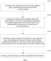
- FIG. 4 is a diagram of the steps of preparation method of an electrode sheet provided by the embodiment of this invention. As shown in FIG. 4 , this embodiment further provides a preparation method of the electrode sheet, which is used to prepare the above electrode sheet.
- the method includes the following steps.
- S101 Providing the first conductive layer 120 and the second conductive layer 130 on the opposite sides of the base layer 110 respectively to form the current collector 100, in which the first conductive layer 120 and the second conductive layer 130 are attached on the opposite sides of the base layer 110 respectively to form the current collector 100 with a sandwich structure.
- a transition layer for connection may also be provided between the first conductive layer 120 and the base layer 110 and between the second conductive layer 130 and the base layer 110.
- S102 Dividing the current collector 100 into a first zone and a second zone along its first direction, coating the active material layers 200 on the opposite sides of the current collector 100 in the first zone, and forming the through hole 140 for enabling the opposite sides of the current collector 100 to be communicated with each other in the second zone of current collector 100, in which the active material layers 200 are coated on both sides of the current collector 100 in the first zone respectively, so that a current generated by the active material layer is collected into the current collector 100.
- the structure of the tab piece 300 can be cut into a body 310 and a connection part 320.
- the body 310 of the tab piece 300 is connected to the first conductive layer 120 of the current collector 100 in the second zone.
- the first end of the connection part 320 is connected to the body 310; and the second end thereof extends through the through hole 140 to the side of the base layer 110 opposite to the first conductive layer 120, and is connected to the second conductive layer 130.
- the connection between the body 310 and the first conductive layer 120 and the connection between the connection part 320 and the second conductive layer 130 may be performed by welding.
- the first conductive layer 120 and the second conductive layer 130 on both sides of the current collector 100 can be connected and conducted through the tab piece 300, which significantly improves the conductivity of the electrode sheet.
- S104 Forming a tab 330 on the tab piece 300 to form an electrode sheet with the tab 330.
- a plurality of tabs 330 with a certain shape and size are formed by die-cutting the part of the tab piece 300 along the part of the current collector 100 which extends in the first direction, so as to obtain an electrode sheet welded with a plurality of tabs 330.
- the charging/discharging circuit of the battery is formed after the tabs 330 are connected to the external circuit.
- Using the plurality of tabs 330 further significantly reduces the resistance while realizing the conduction of the conductive layers on both sides of the composite current collector 100, and improves the electrical performance of the lithium ion battery.
- the current collector 100 is formed after the first conductive layer 120 and the second conductive layer 130 are attached on opposite sides of the base layer 110 respectively. Then the current collector 100 is divided into the first zone and the second zone along its first direction, the active material layers 200 are coated on the opposite sides of the current collector 100 in the first zone respectively, and the through hole 140 for enabling the opposite sides of the current collector 100 to be communicated with each other is formed in the second zone of the current collector 100.
- the first part of the structure of the tab piece 300 is connected to the first conductive layer 120; and the other part of the structure of the tab piece 300 extends through the through hole 140 to the side of the current collector 100 opposite to the first conductive layer 120, and is connected to the second conductive layer 130.
- the tabs 330 are formed by die-cutting the tab piece 300, and the electrode sheet with the tabs 330 is finally formed.
- the conductive layers on both sides of the electrode sheet current collector 100 prepared by the above method may be conducted with each other.
- the arrangement of the plurality of tabs 330 significantly reduces the resistance of the battery, improving the electrical performance of the battery.
- the base layer 110 can reduce the weight of the battery, increase the energy density of the battery and increase the safety performance of the battery.
- FIG. 5 is a schematic structural diagram of a cell formed by winding the electrode sheet provided by the embodiment of this invention.
- the electrode sheet prepared by the above steps are coated with different active materials to obtain the positive electrode sheet 510 and the negative electrode sheet 520, then the positive electrode sheet 510 and the negative electrode sheet 520 are wound together with a separator 530 to obtain a cell 500, and the cell 500 is sealed, injected with electrolyte, aged, subjected to formation and capacity-grading, etc., to finally produce a lithium ion battery.
- an embodiment of this invention provides a laminated battery, which is formed from the positive electrode sheet 510, the negative electrode sheet 520 and the separator 530 by successive lamination.
- the structure, function, preparation method and working principle of the electrode sheets have been introduced in detail in the above content, and will not be repeated here.
- two comparative cells are selected for comparative testing.
- the two cells were named as comparative cell 1 and comparative cell 2 respectively.
- the composition and structure of the cell in the embodiment, the comparative cell 1, and the comparative cell 2 are described respectively in the following.
- the positive current collector adopts an aluminum-polyethylene terephthalate-aluminum foil with a laminated structure
- the active slurry of lithium cobaltate is coated on the current collector
- one end of the current collector is provided with an uncoated area along its first direction, and a through hole is provided in the uncoated area.
- the tab piece is attached to the conductive layer on the side of the uncoated area.
- the tab piece above the through hole is cut to form a small tab piece with a length shorter than the through hole, which is inserted into the through hole. And then the tab piece is welded to the conductive layers on both sides of the uncoated area simultaneously.
- the negative current collector adopts copper foil as a foil, and the graphite active material is coated on the current collector, and the tabs are welded on the uncoated area. Then the positive electrode sheet, the negative electrode sheet, and the separator are wound to obtain a wound cell, which is sealed, injected with electrolyte, and subjected to formation, secondary sealing, and capacity grading to obtain a finished cell.
- the structure and composition of the comparative cell 1 are as follows.
- the positive current collector adopts aluminum foil, and the active slurry of lithium cobaltate is coated on the current collector; at least one end of the current collector is provided with an uncoated area along its second direction; and the uncoated area of the positive current collector is welded with a tab.
- the negative current collector adopts copper foil, the graphite active material is coated on the negative current collector, and the tabs are welded on the uncoated area. Then the positive electrode sheet, the negative electrode sheet, and the separator are wound to obtain a wound cell, which is sealed, injected with electrolyte, and subjected to formation, secondary sealing, and capacity grading to obtain a finished cell.
- the structure and composition of the comparative cell 2 are as follows.
- the positive current collector adopts aluminum-polyethylene terephthalate-aluminum foil with a laminated structure; the active slurry of lithium cobaltate is coated on the current collector; at least one end of the positive current collector is provided with an uncoated area along its second direction; and a tab is welded on the uncoated area of the positive current collector.
- the negative current collector adopts copper foil; the graphite active material is coated on the negative current collector, and a tab is welded on the uncoated area. Then, the positive electrode sheet, the negative electrode sheet, and the separator are wound to obtain a wound cell, which is sealed, injected with electrolyte, and subjected to formation, secondary sealing, and capacity grading to obtain a finished cell.
- the internal resistance test and the heavy object impact test are carried out for the cell in the embodiment, the comparative cell 1, and the comparative cell 2, respectively (the internal resistance of the finished cell is tested by an internal resistance tester, and the heavy object impact test is performed by: taking the battery to be fully charged, arranging the cell on a plane, placing a steel column with a diameter of 15.8 ⁇ 0.2mm in the center of the cell, where a longitudinal axis of the steel column is parallel to the plane, and allowing a heavy object with a mass of 9.1 ⁇ 0.1kg to freely drop from a height of 610 ⁇ 25mm onto the steel column above the center of the battery.), and the following set of data is obtained finally.
- Table 1 Table 1
- the energy density and safety test results of the cell in the embodiment and respective comparative cells Item Internal resistance m ⁇ Energy density Wh/kg Heavy object impact with full charging (number of qualified cells/total number of tested cells) Cell of the embodiment 13 293 20/20 Comparative cell 1 32 280 0/20 Comparative cell 2 50 295 20/20
- This embodiment further provides a lithium ion battery, which includes the above electrode sheet.
- the structure, function, preparation method and working principle of the electrode sheet of the battery have been introduced in detail in the above content, and will not be repeated here.
- connection should be understood in a broad sense, for example, it may be fixedly connected, or it may be connected indirectly through a middle medium, or it may be an internal communication of two elements or an interaction relationship between two elements.
- connection should be understood in a broad sense, for example, it may be fixedly connected, or it may be connected indirectly through a middle medium, or it may be an internal communication of two elements or an interaction relationship between two elements.
- connecting should be understood in a broad sense, for example, it may be fixedly connected, or it may be connected indirectly through a middle medium, or it may be an internal communication of two elements or an interaction relationship between two elements.
Landscapes
- Chemical & Material Sciences (AREA)
- Chemical Kinetics & Catalysis (AREA)
- Electrochemistry (AREA)
- General Chemical & Material Sciences (AREA)
- Engineering & Computer Science (AREA)
- Materials Engineering (AREA)
- Manufacturing & Machinery (AREA)
- Composite Materials (AREA)
- Connection Of Batteries Or Terminals (AREA)
- Cell Electrode Carriers And Collectors (AREA)
- Secondary Cells (AREA)
Abstract
Description
- This invention relates to a technical field of a lithium ion battery, in particular to an electrode sheet and a preparation method thereof, and a lithium ion battery.
- At present, the lithium ion battery has been widely used in consumer electronics, electric vehicles, energy storage, etc. The lithium ion battery is a secondary battery (rechargeable battery) that works mainly based on movement of lithium ions between a positive electrode and a negative electrode. During charging and discharging, lithium ions are intercalated and deintercalated back and forth between the two electrodes; during the charging, lithium ions are deintercalated from the positive electrode and intercalated into the negative electrode through an electrolyte, thereby the negative electrode is in a lithium-rich state; during the discharging, it is exactly the opposite.
- An aluminum foil is used as a positive electrode current collector and a copper foil is used as a negative electrode current collector in a conventional lithium-ion battery. In order to reduce a weight of the battery and increase an energy density of the battery, part of the aluminum foil or part of the copper foil of the current collectors may be replaced with a lighter polymer material. For example, a current collector having a sandwich structure such as aluminum-polymer-aluminum or copper-polymer-copper is used.
- However, since the polymer layer of the current collector in the above composite structure is non-conductive, part of the structure of the current collector is separated by the polymer layer and cannot be electrically connected to a tab welded on the current collector.
- This invention provides an electrode sheet and a preparation method thereof, and a lithium ion battery, so as to realize mutual conduction of conductive layers on both sides of a composite current collector.
- This invention provides an electrode sheet, including a current collector, an active material layer and a tab piece, the current collector includes a base layer, a first conductive layer and a second conductive layer, the first conductive layer and the second conductive layer are respectively arranged on opposite sides of the base layer.
- The current collector is divided into a first zone and a second zone in a first direction thereof; the active material layer is coated on opposite sides of the first zone of the current collector, and the tab piece is connected to the second zone of the current collector.
- The second zone is provided with a through hole for enabling opposite sides of the current collector to be communicated with each other, one part of structure of the tab piece is connected to the first conductive layer, and the other part of structure of the tab piece extends through the through hole to a side of the current collector opposite to the first conductive layer and is connected to the second conductive layer.
- In a possible implementation manner, in the electrode sheet provided by this invention, the tab piece includes a body and a connection part, and the body is connected to the first conductive layer.
- A first end of the connection part is connected to the body, a second end of the connection part extends from the through hole to a side of the current collector opposite to the body, and the second end of the connection part is connected with the second conductive layer.
- In a possible implementation manner, in the electrode sheet provided by this invention, a surface of the first conductive layer away from the base layer has a first connection area, and a surface of the second conductive layer away from the base layer has a second connection area; the first connection area and the second connection area are both connected to the tab piece to make the first conductive layer and the second conductive layer be conducted with each other, and the first connection area and the second connection area are respectively located on two sides of the through hole along the first direction.
- In a possible implementation manner, in the electrode sheet provided by this invention, one end of the tab piece extends to an outside of the current collector in the first direction, and the other end of the tab piece is connected to an inside of the current collector.
- In a possible implementation manner, in the electrode sheet provided by this invention, a part of the tab piece extending to the outside of the current collector in the first direction is provided with at least two tabs for charging/discharging, and the tabs are arranged at intervals along a second direction of the current collector.
- The first direction is perpendicular to the second direction.
- In a possible implementation manner, in the electrode sheet provided by this invention, an amount of the through hole is greater than or equal to one.
- In a possible implementation manner, the electrode sheet provided by this invention further includes a protection member; the protection member covers at least one of the first connection area and the second connection area, and the protection member is located at an inner surface of the current collector.
- In a possible implementation manner, in the electrode sheet provided by this invention, the through hole has an area of S 1, the second zone of the current collector has an area of S0, and an area ratio of the through hole and the second zone is in a range of 0.01≤S1/S0≤0.5.
- This invention provides a preparation method of an electrode sheet, which is configured to prepare the electrode sheet according to any one of the above, including the following steps:
- providing the first conductive layer and the second conductive layer on opposite sides of the base layer to form the current collector;
- coating the active material layers on the opposite sides of the current collector in the first zone, and forming a through hole for enabling the opposite sides of the current collector to be communicated with each other in the second zone of the current collector;
- connecting one part of structure of the tab piece to the first conductive layer, and extending the other part of structure of the tab piece through the through hole to a side of the current collector opposite to the first conductive layer and connecting it to the second conductive layer;
- forming a tab in the tab piece to obtain an electrode sheet with the tab.
- This invention provides a lithium ion battery, which comprises the electrode sheet according to any one of the above.
- In the electrode sheet, its preparation method, and lithium ion battery provided by this invention, the first conductive layer and the second conductive layer are respectively arranged on opposite sides of the base layer to form the current collector. The current collector is divided into the first zone and the second zone in a first direction thereof; the active material layer is coated on opposite sides of the first zone of the current collector, the second zone of the current collector is provided with a through hole communicating with the opposite sides of the current collector, and the tab piece is connected to the second zone. One part of structure of the tab piece is connected to the first conductive layer of the second zone, and the other part of structure of the tab piece extends to a side of the current collector opposite to the first conductive layer through the through hole and is connected to the second conductive layer. The two-part structure of the tab piece is connected with the first conductive layer and the second conductive layer simultaneously, such that the conductive layers on both sides of the current collector are communicated with each other, ensuring the high safety and high energy density of the lithium-ion battery, meanwhile improving the electrical performance of the lithium-ion battery.
- In order to more clearly illustrate the technical solutions in the embodiments of this invention or the prior art, the accompanying drawings that are required in the description of the embodiments or the prior art will be briefly introduced as follows. Obviously, the accompanying drawings in the following description are some embodiments of this invention. Those skilled in the art can also obtain other accompanying drawings based on these accompanying drawings without paying creative work.
-
FIG. 1 is a schematic diagram of a front structure of the electrode sheet provided by the embodiment of this invention. -
FIG. 2 is a cross-sectional view at A-A inFIG. 1 . -
FIG. 3 is a cross-sectional view at B-B inFIG. 1 . -
FIG. 4 is a diagram of the steps of preparation method of the electrode sheet provided by the embodiment of this invention. -
FIG. 5 is a schematic structural diagram of a cell formed by winding the electrode sheet provided by the embodiment of this invention. - Description of reference signs:
- 100-Current collector; 110-Base layer; 120-First conductive layer; 121-First connection area;
- 130-Second conductive layer; 131-Second connection area; 140-Through hole;
- 200 - Active material layer;
- 300-Tab piece; 310-Body; 320-Connection part; 330-Tab;
- 400 - Protection member;
- 500-Cell; 510-Positive electrode sheet; 520-Negative electrode sheet; 530-Separator.
- In order to make the purpose, technical solutions and advantages of the embodiments of this invention clearer, the technical solutions in the embodiments of this invention will be clearly and completely described below in conjunction with the drawings in the embodiments of this invention. Obviously, the described embodiments are part of embodiments of this invention, but not all embodiments. Based on the embodiments of this invention, all other embodiments obtained by those skilled in the art without creative efforts fall within a protection scope of this invention.
- The lithium ion battery is a secondary battery (rechargeable battery) that works mainly based on movement of lithium ions between a positive electrode and a negative electrode. During charge and discharge, lithium ions are intercalated and deintercalated back and forth between the two electrodes. During the charge, lithium ions are deintercalated from the positive electrode and intercalated into the negative electrode through an electrolyte, thereby the negative electrode is in a lithium-rich state; during the discharge, the situation is opposite. As a new type of energy-storage battery, due to its advantages of high energy, long service life, low energy consumption, no harm, no memory effect, small self-discharge, low internal resistance, high cost performance, and less pollution, lithium-ion batteries are gradually showing great advantages in applications, and widely used in various fields such as mobile phone, laptop, video camera, digital camera, electric vehicle, energy storage, and aerospace.
- Conventional lithium-ion batteries adopt aluminum foil as the positive electrode current collector and copper foil as the negative electrode current collector. In order to increase the energy density of the battery and reduce the weight of the battery, part of the aluminum foil and part of the copper foil of the current collector can be replaced with lighter polymer materials. For example, a current collector with a laminated structure such as aluminum-polymer-aluminum or copper-polymer-copper is used. For the current collector with this structure, when the battery experiences a short circuit, the polymer layer inside the current collector will shrink to cut off a current path in the battery after the battery is heated up to a certain temperature, so that it is not prone to burn or explode. Compared with the current collectors of conventional copper foils and aluminum foils, it has better safety.
- However, the current collector polymer layer in the above composite structure is non-conductive, and welding the tab to a surface of one side of the current collector cannot allow a surface of the other side of the current collector to be conductive.
- Based on this, this invention provides an electrode sheet and its preparation method, and a lithium ion battery. The conductive layers on both sides of the current collector of the electrode sheet can be conducted with each other, and lithium ions have high safety and high rate performance.
- Hereinafter, this invention will be described in detail through specific embodiments.
-
FIG. 1 is a schematic diagram of the front structure of an electrode sheet provided by an embodiment of this invention;FIG. 2 is a cross-sectional view at A-A inFIG. 1; and FIG. 3 is a cross-sectional view at B-B inFIG. 1 . - As shown in
FIGs. 1-3 , an electrode sheet provided by this invention includes acurrent collector 100, anactive material layer 200 and atab piece 300. Thecurrent collector 100 includes abase layer 110, a firstconductive layer 120 and a secondconductive layer 130. The firstconductive layer 120 and the secondconductive layer 130 are respectively disposed on opposite sides of thebase layer 110. - The
current collector 100 is divided into a first zone and a second zone in its first direction; theactive material layer 200 is coated on opposite sides of the first zone of thecurrent collector 100, and thetab piece 300 is connected to the second zone of thecurrent collector 100. - The second zone is provided with a through
hole 140 communicating with opposite sides of thecurrent collector 100, one part of structure of thetab piece 300 is connected to the firstconductive layer 120, and the other part of structure of thetab piece 300 extends to a side of thecurrent collector 100 opposite to the firstconductive layer 120 through the throughhole 140, and is connected to the secondconductive layer 130. - In some embodiments, the electrode sheet includes a
current collector 100, anactive material layer 200, and atab piece 300, where thecurrent collector 100 has a laminated structure including a conductive layer and a base layer, and thebase layer 110 is located in the middle of the laminated structure. A firstconductive layer 120 and a secondconductive layer 130 are respectively attached to the front and back sides of thebase layer 110 to form thecurrent collector 100. In order to reduce the weight of thecurrent collector 100 and increase the energy density of the electrode sheet, thebase layer 110 may have pores. In addition, providing pores in thebase layer 110 and filling some conductive materials in the pores can effectively enhance the conductivity of both sides of thebase layer 110, which is beneficial to improve the conductivity of the electrode sheet. - The
current collector 100 is divided into two areas along a first direction of thecurrent collector 100, namely a first zone and a second zone. Theactive material layer 200 is coated on the front and back sides of the first zone of thecurrent collector 100, and thetab piece 300 is connected to the second zone of thecurrent collector 100. Thetab piece 300 is simultaneously connected with the surfaces of the firstconductive layer 120 and the secondconductive layer 130 in the second zone of thecurrent collector 100 that are away from thebase layer 110. - The second zone of the
current collector 100 is provided with a throughhole 140 for enabling the opposite sides of thecurrent collector 100 to be communicated with each other. In this embodiment, the number and shape of the throughhole 140 are not specifically limited. The number of the throughhole 140 may be at least one or multiple; the throughhole 140 may be, but not limited to be, rectangular, circular, polygonal and elliptical. One part of structure of thetab piece 300 is connected to the firstconductive layer 120, and the other part of structure of thetab piece 300 passes through the throughhole 140 and extends to the side of thecurrent collector 100 opposite to the firstconductive layer 120, and then is connected to the secondconductive layer 130. The firstconductive layer 120 and the secondconductive layer 130 are conductively connected through thetab piece 300, so that the conductive layers on both sides of thecurrent collector 100 are conducted to each other, improving the energy density and electrical performance of the electrode sheet. Moreover, thetab piece 300 is connected to one side of thecurrent collector 100, and thecurrent collector 100 is provided with the throughhole 140 and a part of the structure of thetab piece 300 is connected to the conductive layer on the other side of thecurrent collector 100 through the throughhole 140, such that the conductive layers on both sides of thecurrent collector 100 are conducted to each other, which can reduce the thickness of the welding region of thecurrent collector 100 of the electrode sheet, and facilitate the subsequent sealing of the cell. - As shown in
FIG. 2 and FIG. 3 , thetab piece 300 includes abody 310 and aconnection part 320, and thebody 310 is connected to the firstconductive layer 120. A first end of theconnection part 320 is connected to thebody 310, a second end of theconnection part 320 extends through the throughhole 140 to a side of thecurrent collector 100 opposite to thebody 310, and the second end of theconnection part 320 is connected with the secondconductive layer 130. - In a possible implementation, in order to facilitate a conduction of the
tab piece 300 to the firstconductive layer 120 and the secondconductive layer 130, thetab piece 300 is cut to form a two-part structure, that is, theconnection part 320 and thebody 310. Thebody 310 is connected to the firstconductive layer 120; the first end of theconnection part 320 is connected to thebody 310, and the second end of theconnection part 320 extends to the side of thecurrent collector 100 opposite to thebody 310 after passing through the throughhole 140; and the second end of theconnection part 320 is connected to the secondconductive layer 130. Thetab piece 300 is divided into abody 310 and aconnection part 320 connected to thebody 310. While thebody 310 is connected to the firstconductive layer 120, theconnection part 320 is connected to the secondconductive layer 130 after passing through the throughhole 140. In this way, the firstconductive layer 120 and the secondconductive layer 130 of thecurrent collector 100 are connected through thebody 310 and theconnection part 320, which can avoid welding the tabs on the conductive layers on both sides of thecurrent collector 100 simultaneously, so that the thickness of the welding region in thecurrent collector 100 of the electrode sheet becomes smaller, thereby being conducive to the subsequent sealing of the cell. - As shown in
FIG. 3 , a surface of the firstconductive layer 120 away from thebase layer 110 has afirst connection area 121, and a surface of the secondconductive layer 130 away from thebase layer 110 has asecond connection area 131. Thefirst connection area 121 and thesecond connection area 131 are both connected to thetab piece 300, so that the firstconductive layer 120 and the secondconductive layer 130 are connected, and thefirst connection area 121 and thesecond connection area 131 are respectively located on two sides of the throughhole 140 along the first direction. - In order to connect the
body 310 and theconnection part 320 to the firstconductive layer 120 and the secondconductive layer 130 respectively, in some embodiments, thetab piece 300 is connected to the conductive layers on both sides of thecurrent collector 100 using welding technology. Specifically, thefirst connection area 121 is provided on the surface of the firstconductive layer 120 away from thebase layer 110, and thebody 310 of thetab piece 300 is connected to thefirst connection area 121 by the welding technology. Thesecond connection area 131 is provided on the surface of the secondconductive layer 110 away from thebase layer 110, and the second end of theconnection part 320 is connected to thesecond connection area 131 by the welding technology after passing through the throughhole 140. In this way, thetab piece 300 is simultaneously connected to thefirst connection area 121 and thesecond connection area 131 by welding, so that the firstconductive layer 120 and the secondconductive layer 130 are connected to each other, where thefirst connection area 121 and thesecond connection area 131 are respectively located on two sides of the throughhole 140 along the first direction. - As shown in
FIGs. 1-3 , one end of thetab piece 300 extends to the outside of thecurrent collector 100 in the first direction, and the other end of thetab piece 300 is connected to the inside of thecurrent collector 100. The part of thetab piece 300 extending to the outside of thecurrent collector 100 in the first direction is provided withtabs 330 for charge/discharge, and thetabs 330 are arranged at intervals along a second direction of thecurrent collector 100, and the first direction is perpendicular to the second direction. - Specifically, one end of the
tab piece 300 extends out of thecurrent collector 100 along the first direction, and the other end of thetab piece 300 is attached to the surface of the inner side of thecurrent collector 100. The first direction may be a length direction or a width direction of thecurrent collector 100. Preferably, when the electrode sheet is used as a winding-type battery, the first direction is the width direction of thecurrent collector 100 on the electrode sheet, and the second direction is the length direction of thecurrent collector 100 on the electrode sheet. - In this embodiment, in order to facilitate rapid charge/discharge of the battery, the part of the
tab piece 300 extending to the outside of the width of thecurrent collector 100 is punched and cut to form a plurality oftabs 330, and thetabs 330 are arranged at intervals along the second direction of thecurrent collector 100. Thetab 330 is used for charging/discharging the battery after being connected to an external circuit of the battery. Meanwhile, the plurality oftabs 330 can be connected to the external circuit to form multiple equivalent parallel circuits, which reduce resistance of the battery, enhance the charge/discharge capacity of the battery, and further improve the electrical performance of the battery. - As shown in
FIG. 3 , the number of the throughholes 140 is greater than or equal to one. - In a possible manner, the number and shape of the through
holes 140 are not specifically limited, and the number of the throughholes 140 may be at least one or multiple; the throughholes 140 may be, but is not limited to be rectangular, circular, polygonal and elliptical, etc. - As shown in
FIGs. 2 and 3 , the ratio of a distance L1 between the throughhole 140 and an edge of thecurrent collector 100 away from the side where theactive material layer 200 is coated to the width L0 of the second zone of thecurrent collector 100 that is not coated with theactive material layer 200 has a range of 0≤L1/L0<1, and preferably a range of 0.2-0.6, which is convenient for welding and ensures that the throughhole 140 has a sufficient width. - Meanwhile, a shortest distance between the through
hole 140 and the edge of the first zone coated with theactive material layer 200 in thecurrent collector 100 is L2, and a length of L2 is greater than or equal to 4 mm to ensure both operability and a connection strength between thetab piece 300 and thecurrent collector 100. - The distance between the
first connection area 121 of the firstconductive layer 120 and the edge of the throughhole 140 is L3, and L3 is greater than or equal to 1 mm. - The distance between the
first connection area 121 of the firstconductive layer 120 and the outer edge of thecurrent collector 100 is L4, and L4 is greater than or equal to 1 mm. - The width of the second zone of the
current collector 100 which is not coated with theactive material layer 200 is L0, and the width of the first zone of thecurrent collector 100 coated with theactive material layer 200 is L5; the ratio of L0 to L5 has a range of 0<L1 /L0<1, preferably a range of 0.1-0.4, which can ensure convenient welding operation while ensuring sufficient capacity of the battery. - The length of the
tab 330 of thetab piece 300 is L6, the width of thebody 310 of thetab piece 300 attached with the firstconductive layer 120 is L7; the ratio of L6 to L7 has a range of 0.5<L6/L7<5, preferably a range of 1-2, which can facilitate the connection between the cell and the external circuit while ensuring the welding strength between thetab piece 300 and thecurrent collector 100. - A total area of the through
holes 140 of thecurrent collector 100 is S1, and the area of the second zone of thecurrent collector 100 is S0; the ratio of S1 to S0 has a range of 0.01≤S1/S0≤0.5 to ensure that thecurrent collector 100 has sufficient strength. - As shown in
FIGs. 2 and 3 , the electrode sheet in this embodiment further includes aprotection member 400; theprotection member 400 covers at least one of thefirst connection area 121 and thesecond connection area 131, and theprotection member 400 is located on the inner surface of thecurrent collector 100. - In some embodiments, in order to avoid the internal short circuit caused by burrs piercing the separator, in which the burrs are formed in the welded area after the
tab piece 300 is welded to the conductive layers on both sides of thecurrent collector 100, the electrode sheet is protected by setting theprotection member 400. The specific structure of theprotection member 400 is not specifically limited here, and may be a protective adhesive tape or a protective film etc. Theprotection member 400 covers thefirst connection area 121, or the protection member covers thesecond connection area 131, or theprotection member 400 covers both thefirst connection area 121 and thesecond connection area 131. It should be noted that no matter how the protection member covers, it is located on the inner surface of thecurrent collector 100 and will not protrude out of the outer side of thecurrent collector 100. The thickness of theprotection member 400 is 5-50 µm, and theprotection member 400 is an insulating material. - This setting of the
protection member 400 can prevent the burr from piercing the electrode sheet, improving the safety performance of the electrode sheet of the battery and also increasing the connection strength at the welding area. - In this embodiment, the
base layer 110 is a polymer material layer, and both the firstconductive layer 120 and the secondconductive layer 130 are metal layers. Theactive material layer 400 is constituted by the materials including an active material, a conductive agent and an adhesive agent. - Specifically, the
base layer 110 is a polymer layer, and the polymer layer includes one or more of polymer materials and polymer-based composite materials. The polymer constituting thebase layer 110 includes but is not limited to polyamide, polyimide, polyethylene terephthalate, polybutylene terephthalate, polyethylene naphthalate, polycarbonate, polyethylene, polypropylene, ethylene-propylene rubber, acrylonitrile-butadiene-styrene copolymer, polyvinyl alcohol, polystyrene, polyvinyl chloride, polyvinylidene fluoride, polytetrafluoroethylene, sodium polystyrene sulfonate, polyacetylene, silicone rubber, polyoxymethylene, polyphenylene ether, polyphenylene sulfide, polyethylene glycol, polysulfur nitride polymer materials, polyphenylene, polypyrrole, polyaniline, polythiophene, polypyridine, cellulose, starch, protein, epoxy resin, phenolic resin, and derivatives, cross-linked substances of the above materials and copolymers of the above materials, etc. - The first
conductive layer 120 and the secondconductive layer 130 may be at least one of metal conductive material and carbon-based conductive material. The metal conductive material that constitutes the firstconductive layer 120 and the secondconductive layer 130 includes but is not limited to aluminum, copper, titanium, nickel, silver, gold, iron, nickel-copper alloy and aluminum-zirconium alloy, etc. The carbon-based conductive material that constitutes the firstconductive layer 120 and the secondconductive layer 130 includes but is not limited to graphite, acetylene black, graphene, carbon nanotubes, etc. The firstconductive layer 120 and the secondconductive layer 130 may be composed of the same metal material or alloy material, or the firstconductive layer 120 and the secondconductive layer 130 may be composed of different materials. - In addition, the conductive layer material is preferably a metal conductive material, that is, the conductive layer is preferably a metal conductive layer. When the
current collector 100 is a positive electrode current collector, aluminum is usually used as the conductive layer material; when thecurrent collector 100 is a negative electrode current collector, copper is usually used as the conductive layer material. - In some embodiments, a transition layer (not shown) may be provided between the first
conductive layer 120 and thebase layer 110 and between the secondconductive layer 130 and thebase layer 110; and the transition layer is configured to improve a connection strength between the firstconductive layer 120 and thebase layer 110 and between the secondconductive layer 130 and thebase layer 110 to prevent the firstconductive layer 120 and the secondconductive layer 130 from falling off from thebase layer 110. Exemplarily, the material constituting the transition layer includes but is not limited to aluminum oxide, titanium oxide, magnesium oxide, etc. - Generally, the
active material layer 400 is constituted by the materials including an active material, a conductive agent and an adhesive agent. In a specific application, when the electrode sheet is used as a positive electrode sheet, the active material may be a positive active material. The positive active material includes at least one of lithium cobalt oxide (LCO), nickel-cobalt-manganese ternary material (nickel-cobalt-manganese, NCM), nickel-cobalt-aluminum ternary material (nickel-cobalt-aluminum, NCA), nickel-cobalt-manganese-aluminum quaternary material (nickel-cobalt-manganese-aluminum, NCMA), lithium iron phosphate (LFP), lithium manganese phosphate (LMP), lithium vanadium phosphate (LVP), lithium manganate (LMO), and lithium-rich manganese-based material. - When the electrode sheet is used as a negative electrode sheet, the active material may be a negative active material. The negative active material includes at least one of graphite, mesocarbon microspheres, soft carbon, hard carbon, silicon material, silicon oxide material, silicon carbide material, and lithium titanate.
- The conductive agent includes at least one of conductive carbon black, carbon nanotubes, conductive graphite, and graphene.
- The adhesive agent includes at least one of polyvinylidene fluoride, vinylidene fluoride-hexafluoropropylene copolymer, polyamide, polyacrylonitrile, polyacrylate, polyacrylic acid, polyacrylate salt, carboxymethylcellulose sodium, polyvinylpyrrolidone, polyvinyl ether, polymethyl methacrylate, polytetrafluoroethylene, polyhexafluoropropylene and styrene-butadiene rubber.
-
FIG. 4 is a diagram of the steps of preparation method of an electrode sheet provided by the embodiment of this invention. As shown inFIG. 4 , this embodiment further provides a preparation method of the electrode sheet, which is used to prepare the above electrode sheet. - Specifically, the method includes the following steps.
- S101: Providing the first
conductive layer 120 and the secondconductive layer 130 on the opposite sides of thebase layer 110 respectively to form thecurrent collector 100, in which the firstconductive layer 120 and the secondconductive layer 130 are attached on the opposite sides of thebase layer 110 respectively to form thecurrent collector 100 with a sandwich structure. - A transition layer for connection may also be provided between the first
conductive layer 120 and thebase layer 110 and between the secondconductive layer 130 and thebase layer 110. - S102: Dividing the
current collector 100 into a first zone and a second zone along its first direction, coating the active material layers 200 on the opposite sides of thecurrent collector 100 in the first zone, and forming the throughhole 140 for enabling the opposite sides of thecurrent collector 100 to be communicated with each other in the second zone ofcurrent collector 100, in which the active material layers 200 are coated on both sides of thecurrent collector 100 in the first zone respectively, so that a current generated by the active material layer is collected into thecurrent collector 100. - S103: Connecting one part of structure of the
tab piece 300 to the firstconductive layer 120; and extending the other part of structure of thetab piece 300 through the throughhole 140 to a side of thecurrent collector 100 opposite to the firstconductive layer 120 and connecting it to the firstconductive layer 130. - Specifically, the structure of the
tab piece 300 can be cut into abody 310 and aconnection part 320. Thebody 310 of thetab piece 300 is connected to the firstconductive layer 120 of thecurrent collector 100 in the second zone. The first end of theconnection part 320 is connected to thebody 310; and the second end thereof extends through the throughhole 140 to the side of thebase layer 110 opposite to the firstconductive layer 120, and is connected to the secondconductive layer 130. The connection between thebody 310 and the firstconductive layer 120 and the connection between theconnection part 320 and the secondconductive layer 130 may be performed by welding. - The first
conductive layer 120 and the secondconductive layer 130 on both sides of thecurrent collector 100 can be connected and conducted through thetab piece 300, which significantly improves the conductivity of the electrode sheet. - S104: Forming a
tab 330 on thetab piece 300 to form an electrode sheet with thetab 330. Specifically, a plurality oftabs 330 with a certain shape and size are formed by die-cutting the part of thetab piece 300 along the part of thecurrent collector 100 which extends in the first direction, so as to obtain an electrode sheet welded with a plurality oftabs 330. - The charging/discharging circuit of the battery is formed after the
tabs 330 are connected to the external circuit. Using the plurality oftabs 330 further significantly reduces the resistance while realizing the conduction of the conductive layers on both sides of the compositecurrent collector 100, and improves the electrical performance of the lithium ion battery. - In the preparation method of the electrode sheet provided in this embodiment, firstly, the
current collector 100 is formed after the firstconductive layer 120 and the secondconductive layer 130 are attached on opposite sides of thebase layer 110 respectively. Then thecurrent collector 100 is divided into the first zone and the second zone along its first direction, the active material layers 200 are coated on the opposite sides of thecurrent collector 100 in the first zone respectively, and the throughhole 140 for enabling the opposite sides of thecurrent collector 100 to be communicated with each other is formed in the second zone of thecurrent collector 100. Next, the first part of the structure of thetab piece 300 is connected to the firstconductive layer 120; and the other part of the structure of thetab piece 300 extends through the throughhole 140 to the side of thecurrent collector 100 opposite to the firstconductive layer 120, and is connected to the secondconductive layer 130. Finally, thetabs 330 are formed by die-cutting thetab piece 300, and the electrode sheet with thetabs 330 is finally formed. The conductive layers on both sides of the electrode sheetcurrent collector 100 prepared by the above method may be conducted with each other. In addition, the arrangement of the plurality oftabs 330 significantly reduces the resistance of the battery, improving the electrical performance of the battery. Thebase layer 110 can reduce the weight of the battery, increase the energy density of the battery and increase the safety performance of the battery. -
FIG. 5 is a schematic structural diagram of a cell formed by winding the electrode sheet provided by the embodiment of this invention. As shown inFIG. 5 , the electrode sheet prepared by the above steps are coated with different active materials to obtain thepositive electrode sheet 510 and thenegative electrode sheet 520, then thepositive electrode sheet 510 and thenegative electrode sheet 520 are wound together with aseparator 530 to obtain acell 500, and thecell 500 is sealed, injected with electrolyte, aged, subjected to formation and capacity-grading, etc., to finally produce a lithium ion battery. - In addition, an embodiment of this invention provides a laminated battery, which is formed from the
positive electrode sheet 510, thenegative electrode sheet 520 and theseparator 530 by successive lamination. The structure, function, preparation method and working principle of the electrode sheets have been introduced in detail in the above content, and will not be repeated here. - In order to compare and test the energy density and safety performance of the cells formed by the electrode sheets of this embodiment, two comparative cells are selected for comparative testing. The two cells were named as comparative cell 1 and comparative cell 2 respectively. The composition and structure of the cell in the embodiment, the comparative cell 1, and the comparative cell 2 are described respectively in the following.
- The structure and composition of the cell in the embodiment are as follows: the positive current collector adopts an aluminum-polyethylene terephthalate-aluminum foil with a laminated structure; the active slurry of lithium cobaltate is coated on the current collector; one end of the current collector is provided with an uncoated area along its first direction, and a through hole is provided in the uncoated area. The tab piece is attached to the conductive layer on the side of the uncoated area. The tab piece above the through hole is cut to form a small tab piece with a length shorter than the through hole, which is inserted into the through hole. And then the tab piece is welded to the conductive layers on both sides of the uncoated area simultaneously. The negative current collector adopts copper foil as a foil, and the graphite active material is coated on the current collector, and the tabs are welded on the uncoated area. Then the positive electrode sheet, the negative electrode sheet, and the separator are wound to obtain a wound cell, which is sealed, injected with electrolyte, and subjected to formation, secondary sealing, and capacity grading to obtain a finished cell.
- The structure and composition of the comparative cell 1 are as follows. The positive current collector adopts aluminum foil, and the active slurry of lithium cobaltate is coated on the current collector; at least one end of the current collector is provided with an uncoated area along its second direction; and the uncoated area of the positive current collector is welded with a tab. The negative current collector adopts copper foil, the graphite active material is coated on the negative current collector, and the tabs are welded on the uncoated area. Then the positive electrode sheet, the negative electrode sheet, and the separator are wound to obtain a wound cell, which is sealed, injected with electrolyte, and subjected to formation, secondary sealing, and capacity grading to obtain a finished cell..
- The structure and composition of the comparative cell 2 are as follows. The positive current collector adopts aluminum-polyethylene terephthalate-aluminum foil with a laminated structure; the active slurry of lithium cobaltate is coated on the current collector; at least one end of the positive current collector is provided with an uncoated area along its second direction; and a tab is welded on the uncoated area of the positive current collector. The negative current collector adopts copper foil; the graphite active material is coated on the negative current collector, and a tab is welded on the uncoated area. Then, the positive electrode sheet, the negative electrode sheet, and the separator are wound to obtain a wound cell, which is sealed, injected with electrolyte, and subjected to formation, secondary sealing, and capacity grading to obtain a finished cell.
- The internal resistance test and the heavy object impact test are carried out for the cell in the embodiment, the comparative cell 1, and the comparative cell 2, respectively (the internal resistance of the finished cell is tested by an internal resistance tester, and the heavy object impact test is performed by: taking the battery to be fully charged, arranging the cell on a plane, placing a steel column with a diameter of 15.8±0.2mm in the center of the cell, where a longitudinal axis of the steel column is parallel to the plane, and allowing a heavy object with a mass of 9.1±0.1kg to freely drop from a height of 610±25mm onto the steel column above the center of the battery.), and the following set of data is obtained finally.
Table 1. The energy density and safety test results of the cell in the embodiment and respective comparative cells Item Internal resistance mΩ Energy density Wh/kg Heavy object impact with full charging (number of qualified cells/total number of tested cells) Cell of the embodiment 13 293 20/20 Comparative cell 1 32 280 0/20 Comparative cell 2 50 295 20/20 - It can be seen from the data in Table 1 above that the cell in this embodiment has higher energy density and safety performance.
- This embodiment further provides a lithium ion battery, which includes the above electrode sheet. The structure, function, preparation method and working principle of the electrode sheet of the battery have been introduced in detail in the above content, and will not be repeated here.
- Finally, it should be noted that: the above embodiments are only intended to illustrate the technical solutions of this invention, rather than limiting them. Although this invention has been described in detail with reference to the foregoing embodiments, those skilled in the art should understand that: it is still possible to modify the technical solutions described in the foregoing embodiments, or perform equivalent replacements for some or all of the technical features thereof; and these modifications or replacements do not make the essence of the corresponding technical solutions depart from the scope of the technical solutions in the various embodiments of this invention.
- In the description of this invention, it should be noted that unless otherwise specified and limited, the terms "installation/installing", "connection" and "connecting" should be understood in a broad sense, for example, it may be fixedly connected, or it may be connected indirectly through a middle medium, or it may be an internal communication of two elements or an interaction relationship between two elements. For those skilled in the art, the specific meanings of the above terms in this invention can be understood according to specific situations.
- In the description of this invention, it should be understood that the orientation or positional relationship, which is indicated by the terms such as "above", "below", "front", "back", "vertical", "horizontal", "top", "bottom", "inner" and "outer", is based on the orientation and positional relationship shown in the drawings, which is only for the convenience of describing this invention and simplifying the description, rather than indicating or implying that the referred device or element must have a specific orientation and be constructed and operated in a particular orientation, and therefore are not understood to be limitations of the invention.
- The terms "first", "second", and "third" (if any) in the description and claims of this invention and the above drawings are intended to distinguish similar objects and not necessarily to describe a specific order or precedence. It should be understood that such data used are interchangeable under appropriate circumstances such that the embodiments of the invention described herein are, for example, capable of be performed in sequences other than those illustrated or described herein.
- Furthermore, the terms "comprising" and "having", as well as any variations thereof, are intended to cover a non-exclusive inclusion, for example, a process, method, system, product or maintenance tool comprising a series of steps or units are not limited to the steps or elements expressly listed. Instead, other steps or elements which are not explicitly listed or inherent to the process, method, product or maintenance tool may be included.
Claims (10)
- An electrode sheet, characterized by comprising a current collector, an active material layer and a tab piece, wherein the current collector comprises a base layer, a first conductive layer and a second conductive layer, and the first conductive layer and the second conductive layer are arranged on opposite sides of the base layer respectively;the current collector is divided into a first zone and a second zone in a first direction, the active material layer is coated on opposite sides of the current collector in the first zone, and the tab piece is connected to the second zone of the current collector;the second zone is provided with a through hole for enabling the opposite sides of the current collector to be communicated with each other, one part of structure of the tab piece is connected to the first conductive layer, and the other part of structure of the tab piece extends through the through hole to a side of the current collector opposite to the first conductive layer and is connected to the second conductive layer.
- The electrode sheet according to claim 1, wherein the tab piece comprises a body and a connection part, and the body is connected to the first conductive layer;
a first end of the connection part is connected to the body, a second end of the connection part extends from the through hole to a side of the current collector opposite to the body, and the second end of the connection part is connected with the second conductive layer. - The electrode sheet according to claim 2, wherein a surface of the first conductive layer away from the base layer has a first connection area, and a surface of the second conductive layer away from the base layer has a second connection area; the first connection area and the second connection area are both connected to the tab piece to make the first conductive layer and the second conductive layer be conducted with each other, and the first connection area and the second connection area are respectively located on two sides of the through hole along the first direction.
- The electrode sheet according to claim 1, wherein one end of the tab piece extends to an outside of the current collector in the first direction, and the other end of the tab piece is connected to an inside of the current collector.
- The electrode sheet according to claim 4, wherein a part of the tab piece extending to the outside of the current collector in the first direction is provided with at least two tabs for charging/discharging, and the tabs are arranged at intervals along a second direction of the current collector;
the first direction is perpendicular to the second direction. - The electrode sheet according to claim 1, wherein an amount of the through hole is greater than or equal to one.
- The electrode sheet according to claim 3, further comprising a protection member; wherein the protection member covers at least one of the first connection area and the second connection area, and the protection member is located at an inner surface of the current collector.
- The electrode sheet according to claim 1, wherein the through hole has an area of S1, the second zone of the current collector has an area of S0, and an area ratio of the through hole and the second zone is in a range of 0.01≤S1/S0≤0.5.
- A preparation method of an electrode sheet for preparing the electrode sheet according to any one of claims 1-8, comprising following steps:providing the first conductive layer and the second conductive layer on opposite sides of the base layer to form the current collector;coating the active material layers on the opposite sides of the current collector in the first zone, and forming a through hole for enabling the opposite sides of the current collector in the second zone of the current collector;connecting one part of structure of the tab piece to the first conductive layer, and extending the other part of structure of the tab piece through the through hole to a side of the current collector opposite to the first conductive layer and connecting it to the second conductive layer;forming a tab on the tab piece to obtain an electrode sheet with the tab.
- A lithium ion battery, characterized by comprising the electrode sheet according to any one of claims 1-8.
Applications Claiming Priority (2)
| Application Number | Priority Date | Filing Date | Title |
|---|---|---|---|
| CN202110480435.0A CN113241423B (en) | 2021-04-30 | 2021-04-30 | Pole piece and preparation method thereof, and lithium ion battery |
| PCT/CN2022/091044 WO2022228580A1 (en) | 2021-04-30 | 2022-05-05 | Electrode plate and preparation method therefor, and lithium-ion battery |
Publications (2)
| Publication Number | Publication Date |
|---|---|
| EP4266396A1 true EP4266396A1 (en) | 2023-10-25 |
| EP4266396A4 EP4266396A4 (en) | 2025-05-14 |
Family
ID=77131738
Family Applications (1)
| Application Number | Title | Priority Date | Filing Date |
|---|---|---|---|
| EP22795049.0A Pending EP4266396A4 (en) | 2021-04-30 | 2022-05-05 | Electrode plate and manufacturing method therefor, as well as lithium-ion battery |
Country Status (4)
| Country | Link |
|---|---|
| US (1) | US20230369604A1 (en) |
| EP (1) | EP4266396A4 (en) |
| CN (1) | CN113241423B (en) |
| WO (1) | WO2022228580A1 (en) |
Families Citing this family (15)
| Publication number | Priority date | Publication date | Assignee | Title |
|---|---|---|---|---|
| US12230842B2 (en) * | 2020-11-06 | 2025-02-18 | Sk On Co., Ltd. | Electrode for lithium secondary battery and method of manufacturing the same |
| CN113066955B (en) * | 2021-03-11 | 2024-02-13 | 珠海冠宇电池股份有限公司 | An electrode sheet and its application |
| CN113241423B (en) * | 2021-04-30 | 2023-04-18 | 珠海冠宇电池股份有限公司 | Pole piece and preparation method thereof, and lithium ion battery |
| CN116868398A (en) * | 2021-10-29 | 2023-10-10 | 宁德时代新能源科技股份有限公司 | Secondary batteries, battery modules, battery packs and electrical devices |
| CN114068944A (en) * | 2021-11-11 | 2022-02-18 | 惠州赣锋锂电科技有限公司 | Pole piece and its preparation method and application |
| CN114156488A (en) * | 2021-11-29 | 2022-03-08 | 珠海冠宇电池股份有限公司 | Pole piece, preparation method thereof and battery |
| WO2023123501A1 (en) * | 2021-12-31 | 2023-07-06 | 宁德新能源科技有限公司 | Battery and electronic device |
| CN114613932B (en) * | 2022-03-24 | 2024-04-19 | 深圳吉阳智能科技有限公司 | Pole piece structure and battery |
| CN217933932U (en) * | 2022-07-27 | 2022-11-29 | 珠海冠宇电池股份有限公司 | Battery cell structure and battery |
| JP2025531522A (en) * | 2022-09-29 | 2025-09-19 | 寧徳新能源科技有限公司 | Electrochemical equipment and power consumers |
| CN115332737B (en) * | 2022-10-17 | 2023-10-10 | 宁德新能源科技有限公司 | A pole piece, electrochemical device and electronic device |
| CN115692723B (en) * | 2022-11-08 | 2024-01-23 | 厦门海辰储能科技股份有限公司 | Composite current collector, battery cell, battery and preparation method of composite current collector |
| CN115870560B (en) * | 2022-12-30 | 2024-01-26 | 重庆太蓝新能源有限公司 | Cutting mechanism and packaging method |
| EP4421971A4 (en) * | 2023-01-09 | 2025-07-09 | Contemporary Amperex Technology Hong Kong Ltd | BATTERY ELECTRODE PLATE, ELECTRODE ASSEMBLY, BATTERY CELL, BATTERY AND ELECTRICAL DEVICE |
| KR20250140844A (en) * | 2024-03-19 | 2025-09-26 | 삼성에스디아이 주식회사 | Electrode plate, electrode assembly and rechargeable battery including the same |
Family Cites Families (18)
| Publication number | Priority date | Publication date | Assignee | Title |
|---|---|---|---|---|
| JP4967230B2 (en) * | 2004-12-07 | 2012-07-04 | 日産自動車株式会社 | Battery structure |
| CN2872606Y (en) * | 2005-12-01 | 2007-02-21 | 深圳市比克电池有限公司 | Coiling lithium-ion battery unit and lithium-ion battery thereof |
| JP2010003653A (en) * | 2008-06-23 | 2010-01-07 | Sumitomo Electric Ind Ltd | Battery |
| JP5690575B2 (en) * | 2010-12-16 | 2015-03-25 | シャープ株式会社 | Non-aqueous secondary battery |
| JP6472025B2 (en) * | 2015-02-18 | 2019-02-20 | セイコーインスツル株式会社 | Electrochemical cell |
| CN205303580U (en) * | 2016-01-22 | 2016-06-08 | 宁德时代新能源科技股份有限公司 | Lithium ion battery pole piece and contain lithium ion battery of this pole piece |
| CN108428848B (en) * | 2017-11-22 | 2021-03-26 | 宁德时代新能源科技股份有限公司 | Electrode member, electrode assembly and rechargeable battery |
| CN108281609B (en) * | 2018-03-27 | 2023-07-28 | 横店集团东磁股份有限公司 | Positive electrode plate with tab, preparation method thereof and lithium ion battery comprising positive electrode plate |
| CN108767262B (en) * | 2018-05-30 | 2020-09-25 | 中航锂电(洛阳)有限公司 | Plastic film for current collector, preparation method of current collector, pole piece and energy storage device |
| KR102097444B1 (en) * | 2019-01-30 | 2020-04-06 | 주식회사 유앤에스에너지 | Current collector for positive electrodes |
| CN111755700A (en) * | 2019-03-29 | 2020-10-09 | 宁德新能源科技有限公司 | Composite current collector, electrode sheet and cell using the composite current collector |
| CN210897473U (en) * | 2019-11-19 | 2020-06-30 | 深圳市海鸿新能源技术有限公司 | Pole piece of secondary battery and secondary battery |
| CN111048787A (en) * | 2019-12-11 | 2020-04-21 | 合肥国轩高科动力能源有限公司 | A kind of manufacturing method of flexible composite current collector |
| CN111952541B (en) * | 2020-09-14 | 2022-05-06 | 珠海冠宇电池股份有限公司 | A positive electrode sheet and preparation method thereof, and battery |
| CN112670435A (en) * | 2020-12-17 | 2021-04-16 | 惠州市豪鹏科技有限公司 | Preparation method of battery pole piece |
| CN113066955B (en) * | 2021-03-11 | 2024-02-13 | 珠海冠宇电池股份有限公司 | An electrode sheet and its application |
| CN113241423B (en) * | 2021-04-30 | 2023-04-18 | 珠海冠宇电池股份有限公司 | Pole piece and preparation method thereof, and lithium ion battery |
| CN114156488A (en) * | 2021-11-29 | 2022-03-08 | 珠海冠宇电池股份有限公司 | Pole piece, preparation method thereof and battery |
-
2021
- 2021-04-30 CN CN202110480435.0A patent/CN113241423B/en active Active
-
2022
- 2022-05-05 EP EP22795049.0A patent/EP4266396A4/en active Pending
- 2022-05-05 WO PCT/CN2022/091044 patent/WO2022228580A1/en not_active Ceased
-
2023
- 2023-07-24 US US18/225,649 patent/US20230369604A1/en active Pending
Also Published As
| Publication number | Publication date |
|---|---|
| CN113241423B (en) | 2023-04-18 |
| WO2022228580A1 (en) | 2022-11-03 |
| EP4266396A4 (en) | 2025-05-14 |
| US20230369604A1 (en) | 2023-11-16 |
| CN113241423A (en) | 2021-08-10 |
Similar Documents
| Publication | Publication Date | Title |
|---|---|---|
| EP4266396A1 (en) | Electrode plate and preparation method therefor, and lithium-ion battery | |
| CN113097662B (en) | Battery pole piece, preparation method thereof and lithium ion battery | |
| JP5217076B2 (en) | Lithium ion battery | |
| EP0949699B1 (en) | Electrical connection structure in a lithium secondary battery | |
| US20130177787A1 (en) | Current collector and nonaqueous secondary battery | |
| US20130177788A1 (en) | Nonaqueous secondary battery | |
| KR100686804B1 (en) | Electrode assembly having an ultra high capacity capacitor and a lithium secondary battery comprising the same | |
| KR101664244B1 (en) | Method forming electrode surface pattern and the electrode manufactured by the method and secondary battery including the same | |
| US20100291444A1 (en) | Multilayer coatings for rechargeable batteries | |
| JPH11238528A (en) | Lithium secondary battery | |
| CN113285055B (en) | An electrode sheet and its application | |
| KR101999529B1 (en) | Pouch-Type Secondary Battery Having Electrode Lead with Couple Notch | |
| KR20180119106A (en) | Pouch Type Lithium Secondary Battery comprising Electrode Lead using Electric-Conductive Polymer | |
| CN114156488A (en) | Pole piece, preparation method thereof and battery | |
| CN113285054B (en) | An electrode sheet and its application | |
| JP7740351B2 (en) | Secondary battery and manufacturing method thereof | |
| KR20170071881A (en) | Electrode for Secondary Battery Having Coating Layer of Preventing Combustion and Secondary Battery Comprising the Same | |
| US7166387B2 (en) | Thin battery with an electrode having a higher strength base portion than a tip portion | |
| KR101476523B1 (en) | Electrode of secondary battery | |
| JP7130920B2 (en) | Non-aqueous electrolyte secondary battery, method for designing non-aqueous electrolyte secondary battery, and method for manufacturing non-aqueous electrolyte secondary battery | |
| KR20190051252A (en) | Electrode structure and secondary battery including the same | |
| KR101520345B1 (en) | Three dimensional electrode assembly and manufacturing method of the same | |
| JP2005123058A (en) | Nonaqueous electrolyte secondary battery | |
| KR20140072794A (en) | Non-aqueous electrolyte rechargeable battery pack | |
| JP2006244833A (en) | Lithium secondary battery and manufacturing method thereof |
Legal Events
| Date | Code | Title | Description |
|---|---|---|---|
| STAA | Information on the status of an ep patent application or granted ep patent |
Free format text: STATUS: THE INTERNATIONAL PUBLICATION HAS BEEN MADE |
|
| PUAI | Public reference made under article 153(3) epc to a published international application that has entered the european phase |
Free format text: ORIGINAL CODE: 0009012 |
|
| STAA | Information on the status of an ep patent application or granted ep patent |
Free format text: STATUS: REQUEST FOR EXAMINATION WAS MADE |
|
| 17P | Request for examination filed |
Effective date: 20230719 |
|
| AK | Designated contracting states |
Kind code of ref document: A1 Designated state(s): AL AT BE BG CH CY CZ DE DK EE ES FI FR GB GR HR HU IE IS IT LI LT LU LV MC MK MT NL NO PL PT RO RS SE SI SK SM TR |
|
| DAV | Request for validation of the european patent (deleted) | ||
| DAX | Request for extension of the european patent (deleted) | ||
| A4 | Supplementary search report drawn up and despatched |
Effective date: 20250414 |
|
| RIC1 | Information provided on ipc code assigned before grant |
Ipc: H01M 4/02 20060101ALI20250408BHEP Ipc: H01M 50/595 20210101ALI20250408BHEP Ipc: H01M 50/538 20210101ALI20250408BHEP Ipc: H01M 50/536 20210101ALI20250408BHEP Ipc: H01M 50/533 20210101ALI20250408BHEP Ipc: H01M 10/0525 20100101ALI20250408BHEP Ipc: H01M 4/70 20060101ALI20250408BHEP Ipc: H01M 4/04 20060101ALI20250408BHEP Ipc: H01M 50/528 20210101ALI20250408BHEP Ipc: H01M 50/586 20210101ALI20250408BHEP Ipc: H01M 4/66 20060101ALI20250408BHEP Ipc: H01M 4/139 20100101ALI20250408BHEP Ipc: H01M 4/13 20100101AFI20250408BHEP |