EP4266395A1 - Electrode sheet and application thereof - Google Patents
Electrode sheet and application thereof Download PDFInfo
- Publication number
- EP4266395A1 EP4266395A1 EP22766386.1A EP22766386A EP4266395A1 EP 4266395 A1 EP4266395 A1 EP 4266395A1 EP 22766386 A EP22766386 A EP 22766386A EP 4266395 A1 EP4266395 A1 EP 4266395A1
- Authority
- EP
- European Patent Office
- Prior art keywords
- region
- tab
- current collector
- electrode plate
- active layer
- Prior art date
- Legal status (The legal status is an assumption and is not a legal conclusion. Google has not performed a legal analysis and makes no representation as to the accuracy of the status listed.)
- Granted
Links
Images

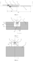


Classifications
-
- H—ELECTRICITY
- H01—ELECTRIC ELEMENTS
- H01M—PROCESSES OR MEANS, e.g. BATTERIES, FOR THE DIRECT CONVERSION OF CHEMICAL ENERGY INTO ELECTRICAL ENERGY
- H01M50/00—Constructional details or processes of manufacture of the non-active parts of electrochemical cells other than fuel cells, e.g. hybrid cells
- H01M50/50—Current conducting connections for cells or batteries
- H01M50/531—Electrode connections inside a battery casing
- H01M50/533—Electrode connections inside a battery casing characterised by the shape of the leads or tabs
-
- H—ELECTRICITY
- H01—ELECTRIC ELEMENTS
- H01M—PROCESSES OR MEANS, e.g. BATTERIES, FOR THE DIRECT CONVERSION OF CHEMICAL ENERGY INTO ELECTRICAL ENERGY
- H01M4/00—Electrodes
- H01M4/02—Electrodes composed of, or comprising, active material
- H01M4/13—Electrodes for accumulators with non-aqueous electrolyte, e.g. for lithium-accumulators; Processes of manufacture thereof
-
- H—ELECTRICITY
- H01—ELECTRIC ELEMENTS
- H01M—PROCESSES OR MEANS, e.g. BATTERIES, FOR THE DIRECT CONVERSION OF CHEMICAL ENERGY INTO ELECTRICAL ENERGY
- H01M10/00—Secondary cells; Manufacture thereof
- H01M10/05—Accumulators with non-aqueous electrolyte
- H01M10/052—Li-accumulators
-
- H—ELECTRICITY
- H01—ELECTRIC ELEMENTS
- H01M—PROCESSES OR MEANS, e.g. BATTERIES, FOR THE DIRECT CONVERSION OF CHEMICAL ENERGY INTO ELECTRICAL ENERGY
- H01M10/00—Secondary cells; Manufacture thereof
- H01M10/05—Accumulators with non-aqueous electrolyte
- H01M10/052—Li-accumulators
- H01M10/0525—Rocking-chair batteries, i.e. batteries with lithium insertion or intercalation in both electrodes; Lithium-ion batteries
-
- H—ELECTRICITY
- H01—ELECTRIC ELEMENTS
- H01M—PROCESSES OR MEANS, e.g. BATTERIES, FOR THE DIRECT CONVERSION OF CHEMICAL ENERGY INTO ELECTRICAL ENERGY
- H01M10/00—Secondary cells; Manufacture thereof
- H01M10/05—Accumulators with non-aqueous electrolyte
- H01M10/058—Construction or manufacture
- H01M10/0587—Construction or manufacture of accumulators having only wound construction elements, i.e. wound positive electrodes, wound negative electrodes and wound separators
-
- H—ELECTRICITY
- H01—ELECTRIC ELEMENTS
- H01M—PROCESSES OR MEANS, e.g. BATTERIES, FOR THE DIRECT CONVERSION OF CHEMICAL ENERGY INTO ELECTRICAL ENERGY
- H01M4/00—Electrodes
- H01M4/02—Electrodes composed of, or comprising, active material
- H01M4/64—Carriers or collectors
- H01M4/66—Selection of materials
- H01M4/661—Metal or alloys, e.g. alloy coatings
-
- H—ELECTRICITY
- H01—ELECTRIC ELEMENTS
- H01M—PROCESSES OR MEANS, e.g. BATTERIES, FOR THE DIRECT CONVERSION OF CHEMICAL ENERGY INTO ELECTRICAL ENERGY
- H01M4/00—Electrodes
- H01M4/02—Electrodes composed of, or comprising, active material
- H01M4/64—Carriers or collectors
- H01M4/66—Selection of materials
- H01M4/665—Composites
- H01M4/667—Composites in the form of layers, e.g. coatings
-
- H—ELECTRICITY
- H01—ELECTRIC ELEMENTS
- H01M—PROCESSES OR MEANS, e.g. BATTERIES, FOR THE DIRECT CONVERSION OF CHEMICAL ENERGY INTO ELECTRICAL ENERGY
- H01M4/00—Electrodes
- H01M4/02—Electrodes composed of, or comprising, active material
- H01M4/64—Carriers or collectors
- H01M4/66—Selection of materials
- H01M4/668—Composites of electroconductive material and synthetic resins
-
- H—ELECTRICITY
- H01—ELECTRIC ELEMENTS
- H01M—PROCESSES OR MEANS, e.g. BATTERIES, FOR THE DIRECT CONVERSION OF CHEMICAL ENERGY INTO ELECTRICAL ENERGY
- H01M4/00—Electrodes
- H01M4/02—Electrodes composed of, or comprising, active material
- H01M4/64—Carriers or collectors
- H01M4/70—Carriers or collectors characterised by shape or form
-
- H—ELECTRICITY
- H01—ELECTRIC ELEMENTS
- H01M—PROCESSES OR MEANS, e.g. BATTERIES, FOR THE DIRECT CONVERSION OF CHEMICAL ENERGY INTO ELECTRICAL ENERGY
- H01M50/00—Constructional details or processes of manufacture of the non-active parts of electrochemical cells other than fuel cells, e.g. hybrid cells
- H01M50/50—Current conducting connections for cells or batteries
- H01M50/531—Electrode connections inside a battery casing
- H01M50/534—Electrode connections inside a battery casing characterised by the material of the leads or tabs
-
- H—ELECTRICITY
- H01—ELECTRIC ELEMENTS
- H01M—PROCESSES OR MEANS, e.g. BATTERIES, FOR THE DIRECT CONVERSION OF CHEMICAL ENERGY INTO ELECTRICAL ENERGY
- H01M50/00—Constructional details or processes of manufacture of the non-active parts of electrochemical cells other than fuel cells, e.g. hybrid cells
- H01M50/50—Current conducting connections for cells or batteries
- H01M50/531—Electrode connections inside a battery casing
- H01M50/536—Electrode connections inside a battery casing characterised by the method of fixing the leads to the electrodes, e.g. by welding
-
- Y—GENERAL TAGGING OF NEW TECHNOLOGICAL DEVELOPMENTS; GENERAL TAGGING OF CROSS-SECTIONAL TECHNOLOGIES SPANNING OVER SEVERAL SECTIONS OF THE IPC; TECHNICAL SUBJECTS COVERED BY FORMER USPC CROSS-REFERENCE ART COLLECTIONS [XRACs] AND DIGESTS
- Y02—TECHNOLOGIES OR APPLICATIONS FOR MITIGATION OR ADAPTATION AGAINST CLIMATE CHANGE
- Y02E—REDUCTION OF GREENHOUSE GAS [GHG] EMISSIONS, RELATED TO ENERGY GENERATION, TRANSMISSION OR DISTRIBUTION
- Y02E60/00—Enabling technologies; Technologies with a potential or indirect contribution to GHG emissions mitigation
- Y02E60/10—Energy storage using batteries
-
- Y—GENERAL TAGGING OF NEW TECHNOLOGICAL DEVELOPMENTS; GENERAL TAGGING OF CROSS-SECTIONAL TECHNOLOGIES SPANNING OVER SEVERAL SECTIONS OF THE IPC; TECHNICAL SUBJECTS COVERED BY FORMER USPC CROSS-REFERENCE ART COLLECTIONS [XRACs] AND DIGESTS
- Y02—TECHNOLOGIES OR APPLICATIONS FOR MITIGATION OR ADAPTATION AGAINST CLIMATE CHANGE
- Y02P—CLIMATE CHANGE MITIGATION TECHNOLOGIES IN THE PRODUCTION OR PROCESSING OF GOODS
- Y02P70/00—Climate change mitigation technologies in the production process for final industrial or consumer products
- Y02P70/50—Manufacturing or production processes characterised by the final manufactured product
Definitions
- the present application pertains to the technical field of lithium-ion batteries, and specifically relates to an electrode plate and an application thereof.
- lithium-ion batteries Since the first commercial lithium-ion battery was released by Sony in 1991, lithium-ion batteries have been widely used in fields such as consumer electronics, electric vehicles, and energy storage.
- a conventional lithium-ion battery generally uses aluminum foil as a positive electrode current collector and copper foil as a negative electrode current collector.
- aluminum foil or copper foil can be combined with a lighter polymer material to form a novel current collector, such as aluminum-polymer-aluminum current collector, and copper-polymer-copper current collector.
- the novel current collector with a sandwich structure not only has smaller surface density, but also can reduce weight of a lithium-ion battery and improve the energy density.
- the present application provides an electrode plate, and the electrode plate may conduct two surfaces of a current collector, and may improve energy density of a lithium-ion battery.
- the present application provides an electrochemical apparatus and the lithium-ion battery has a high energy density.
- the present application provides an electrode plate, where the electrode plate includes a current collector, an active layer, and a tab.
- a first function surface of the current collector includes a first active layer region and a first tab region
- a second function surface of the current collector includes a second active layer region corresponding to the first active layer region and a second tab region corresponding to the first tab region
- the active layer is disposed in the first active layer region and/or the second active layer region.
- the first tab region is provided with N through holes penetrating to the second tab region, the tab passes through the through hole, and a first section of the tab is connected to the first tab region to form a first connection region and a second section of the tab is connected to the second tab region to form a second connection region, where N ⁇ 1.
- the tab further includes a third section, and the third section extends from a function surface of the current collector and is connected to an external tab.
- a minimum distance between edges of M through holes and an edge of the current collector is W1, where W1 ⁇ 1 mm, and M ⁇ N.
- a ratio of the minimum distance W1 between the edges of the M through holes and the edge of the current collector to a width W0 of the first tab region and/or the second tab region is (0.2-0.8):1.
- W0 ranges from 10 mm to 100 mm.
- a minimum distance between the edges of the M through holes and an edge of the first active layer region and/or the second active layer region is L1, where L1 ⁇ 2 mm.
- a width of the first connection region and/or the second connection region ranges from 1 mm to ((W0/2)-2) mm.
- a minimum distance between an edge of the first connection region and/or the second connection region and the edges of the M through holes is greater than or equal to 1 mm; and/or in the width direction of the current collector, a minimum distance between an edge of the first connection region and/or the second connection region and the edge of the current collector is greater than or equal to 1 mm.
- a protective layer is disposed on the first function surface and/or the second function surface, the protective layer covers each of W through holes, and the protective layer has openings at corresponding positions of the W through holes, where W ⁇ N.
- a thickness of the protective layer ranges from 0.5 ⁇ m to 50 ⁇ m.
- an area of the protective layer is 1.2-5 times an area of the M through holes.
- the current collector includes a first conductive layer, an insulation layer, and a second conductive layer that are stacked.
- the first function surface is a surface, away from the insulation layer, of the first conductive layer
- the second function surface is a surface, away from the insulation layer, of the second conductive layer.
- the present application further provides an electrochemical apparatus, including the foregoing electrode plate.
- the electrode plate provided in the present application includes a current collector, an active layer, and a tab.
- a first function surface of the current collector includes a first active layer region and a first tab region
- a second function surface of the current collector includes a second active layer region corresponding to the first active layer region and a second tab region corresponding to the first tab region
- the active layer is disposed in the first active layer region and/or the second active layer region.
- the first tab region is provided with N through holes penetrating to the second tab region, the tab passes through the through hole, and a first section of the tab is connected to the first tab region to form a first connection region and a second section of the tab is connected to the second tab region to form a second connection region, where N ⁇ 1.
- a first tab region is provided with a through hole penetrating to a second tab region, a tab passes through the through hole, and two ends of a tab are respectively connected to the first tab region and the second tab region, so that two sides of a current collector may be conducted, thereby improving energy density of a lithium-ion battery.
- FIG. 1 is a top view of a current collector in the present application.
- a “length direction L” and a “width direction W” of the current collector are rectangles.
- the length direction L of the current collector is a direction in which the largest side length of a function surface of the current collector is located
- the width direction W of the current collector is a direction in which the smallest side length of a function surface of the current collector is located.
- a width of a first tab region and/or a second tab region is defined as W0 in the present application
- a size of the first tab region and/or the second tab region is W0 in a width direction of the current collector.
- FIG. 2 is a top view of an electrode plate in a first implementation of the present application.
- FIG. 3 is a first cross-sectional view taken along the line X-X in FIG. 2 of the present application.
- FIG. 4 is a second cross-sectional view taken along the line X-X in FIG. 2 of the present application.
- FIG. 5 is a top view of an electrode plate in a second implementation of the present application.
- FIG. 6 is a top view of an electrode plate in a third implementation of the present application.
- FIG. 7 is a cross-sectional view taken along the line X-X in FIG. 5 or FIG. 6 of the present application. As shown in FIG. 2 to FIG. 7 , the present application provides an electrode plate including a current collector, an active layer, and a tab 1.
- a first function surface of the current collector includes a first active layer region 2 and a first tab region 3
- a second function surface of the current collector includes a second active layer region 8 corresponding to the first active layer region 2 and a second tab region 6 corresponding to the first tab region 3
- the active layer is disposed in the first active layer region 1 and/or the second active layer region 8.
- the first tab region 3 is provided with N through holes 4 penetrating to the second tab region 6, the tab 1 passes through a through hole 4, and a first section of the tab 1 is connected to the first tab region 3 to form a first connection region 5 and a second section of the tab 1 is connected to the second tab region 6 to form a second connection region 7, where N ⁇ 1.
- the first tab region 3 in the present application may be disposed on a side in a length direction of the first active layer region 2.
- the first tab region 3 in the present application may alternatively be disposed on a side in a width direction of the first active layer region 2, and three sides of the first tab region 3 are adjacent to the first active layer region 2.
- the first tab region 3 in the present application may alternatively be disposed on a side in a width direction of the first active layer region 2, and one side of the first tab region 3 is adjacent to the first active layer region 2.
- the second tab region 6 corresponds to the first tab region 3
- the second active layer region 8 corresponds to the first active layer region 2. It may be understood that a projection of the second tab region 6 on the first tab region 3 coincides fully with the first tab region 3, and a projection of the second active layer region 8 on the first active layer region 2 coincides fully with the first active layer region 2.
- the active layer in the present application may be disposed at the first active layer region 2, may be disposed at the second active layer region 8, or may be disposed at both the first active layer region 2 and the second active layer region 8.
- the first tab region 3 is provided with N through holes 4 penetrating to the second tab region 6, and the tab 1 passes through a through hole 4.
- the electrode plate in the present application may have n tabs 1, where n ⁇ N.
- n is equal to N
- each tab 1 passes through one through hole 4, a first section of each tab 1 is connected to the first tab region 3 to form a first connection region 5, and a second section of each tab 1 is connected to the second tab region 6 to form a second connection region 7.
- each tab 1 passes through one through hole 4, a first section of each tab 1 is connected to the first tab region 3 to form a first connection region 5, a second section of each tab 1 is connected to the second tab region 6 to form a second connection region 7, and a remaining through hole 4 is reserved.
- the tab 1 further includes a third section, and the third section extends from a function surface of the current collector and is configured to be connected to an external tab.
- a shape of the through hole 4 is not limited in the present application, and any shape of a through hole through which the tab 1 may pass is within the protection scope of the present application.
- the shape of the through hole 4 may be rectangular, circular, polyhedral, or rectangular + semicircular. In a specific implementation, the shape of the through hole 4 is rectangular + semicircular.
- the first connection region 5 refers to a position where the tab 1 and the first tab region 3 are fixed
- the second connection region 7 refers to a position where the tab 1 and the second tab region 6 are fixed. If the tab 1 is welded to the first tab region 3 and the second tab region 6 separately, the first connection region 5 is a region in which a solder joint formed when the tab 1 is welded to the first tab region 3 is located, and the second connection region 7 is a region in which a solder joint formed when the tab 1 is welded to the second tab region 6 is located.
- first connection region 5 and the second connection region 7 are not limited in the present application. As shown in FIG. 3 , the first connection region 5 and the second connection region 7 may be located on two sides of the through hole 4, respectively. As shown in FIG. 4 , the first connection region 5 and the second connection region 7 may be located on a same side of the through hole 4.
- the current collector includes a first conductive layer, an insulation layer, and a second conductive layer that are stacked; and the first function surface is the first conductive layer and the second function surface is the second conductive layer.
- the insulation layer may swell, so that the first conductive layer and the second conductive layer fall off from the insulation layer, internal current of the battery is cut off, and safety of the battery is improved.
- a material of the first conductive layer or the second conductive layer may be a metal or an alloy, which includes, but is not limited to, at least one of aluminum, copper, nickel, silver, gold, or iron.
- the materials of the first conductive layer and the second conductive layer may be the same or different.
- a material of the insulation layer may be a polymer including, but not limited to, at least one of Polyethylene terephthalate (PET), Polypropylene (PP), Polyethylene (PE), Polyimide (PI), Polyether ketone (PEK), or Polyphenylene sulfide (PPS).
- PET Polyethylene terephthalate
- PP Polypropylene
- PE Polyethylene
- PE Polyimide
- PEK Polyether ketone
- PPS Polyphenylene sulfide
- a transition layer may be further included between the first conductive layer and the insulation layer and/or between the second conductive layer and the insulation layer, and a material of the transition layer includes, but is not limited to, at least one of aluminum oxide, magnesium oxide, or titanium oxide.
- the first conductive layer, the second conductive layer, or the insulation layer may further be provided with a through hole.
- a specific shape of the through hole is not limited in the present application.
- the shape of the through hole may be rectangular, circular, polyhedral, or rectangular + semicircular. In a specific implementation, the shape of the through hole is rectangular + semicircular.
- the electrode plate in the present application may be a positive electrode plate or may be a negative electrode plate.
- the active layer in the present application is a positive electrode active layer disposed on a surface of a positive electrode current collector.
- the positive electrode active layer is obtained by drying a positive electrode active slurry, and the positive electrode active slurry includes a positive electrode active material, a conductive agent, and a binder.
- the positive electrode active material includes at least one of Lithium Cobalt Oxide (LCO), Nickel Cobalt Manganese ternary material (NCM), Nickel Cobalt Aluminum ternary material (NCA), Nickel Cobalt Manganese Aluminum quaternary material (NCMA), Lithium Ferrous Phosphate (LFP), Lithium Manganese Phosphate (LMP), Lithium Vanadium Phosphate (LVP), Lithium Manganate Oxide (LMO), or a lithium-rich manganese-base material.
- LCO Lithium Cobalt Oxide
- NCM Nickel Cobalt Manganese ternary material
- NCA Nickel Cobalt Aluminum ternary material
- NCMA Nickel Cobalt Manganese Aluminum quaternary material
- LFP Lithium Ferrous Phosphate
- LMP Lithium Manganese Phosphate
- LVP Lithium Vanadium Phosphate
- LMO Lithium Manganate Oxide
- the active layer in the present application is a negative electrode active layer disposed on a surface of a negative electrode current collector.
- the negative electrode active layer is obtained by drying a negative electrode active slurry, and the negative electrode active slurry includes a negative electrode active material, a conductive agent, and a binder.
- the negative electrode active material includes at least one of graphite, mesocarbon microbead, soft carbon, hard carbon, a silicon material, a silicon oxide material, a silicon carbon material, or lithium titanate.
- the conductive agent in the positive electrode active slurry and the negative electrode active slurry includes at least one of conductive carbon black, carbon nanotubes, conductive graphite, or graphene.
- the binder in the positive electrode active slurry and the negative electrode active slurry includes at least one of polyvinylidene fluoride, a copolymer of vinylidene fluoride-hexafluoropropylene, polyamide, polyacrylonitrile, polyacrylic acid ester, polyacrylic acid, polyacrylate, sodium carboxymethyl cellulose, polyvinylpyrrolidone, polyvinyl ether, polymethyl methacrylate, polytetrafluoroethylene, polyhexafluoropropylene, or styrene-butadiene rubber.
- the through hole 4 penetrating through the first tab region 3 and the second tab region 6 is provided, the tab 1 passes through the through hole 4, the first section of the tab 1 is connected to the first tab region 3, and the second section of the tab 1 is connected to the second tab region 6, so that two sides of the current collector may be conducted, thereby improving energy density of a lithium-ion battery.
- a minimum distance between edges of M through holes 4 and an edge of the current collector is W1, where W1 ⁇ 1 mm, and M ⁇ N.
- the minimum distance between edges of the through holes 4 and an edge of the current collector means a distance between an edge of the closest through hole and the edge of the current collector. It may be understood that, in the present application, a minimum distance between edges of at least M through holes 4 and the edge of the current collector is W1, where W1 ⁇ 1 mm. A specific distance is reserved between the edges of the through holes 4 and the current collector, so that service life of the electrode plate may be prolonged.
- a ratio of the minimum distance W1 between the edges of the M through holes 4 and the edge of the current collector to a width W0 of the first tab region 3 and/or the second tab region 6 is (0.2-0.8): 1.
- the ratio of W1 to W0 is too large, it means that an area of a through hole 4 is too small to be passed through by the tab 1. If the ratio of W1 to W0 is too small, it means that an area of a through hole 4 is too large, the electrode plate is easily damaged during long-term use, and service life is short.
- the ratio of W1 to W0 is defined as (0.2-0.8): 1 in the present application, so that the tab 1 may be allowed to pass through the through hole 4 normally while ensuring the service life of the electrode plate. In a specific implementation, W0 ranges from 10 mm to 100 mm.
- a minimum distance between the edges of the M through holes 4 and an edge of the first active layer region 2 and/or the second active layer region 8 is L1, where L1 ⁇ 2 mm.
- a width of the first connection region 5 and/or the second connection region 7 ranges from 1 mm to ((W0/2)-2) mm.
- the width of the first connection region 5 and/or the second connection region 7 when the width of the first connection region 5 and/or the second connection region 7 is too large, the energy density of the electrode plate is reduced. When the width of the first connection region 5 and/or the second connection region 7 is too small, the service life of the electrode plate is short.
- the width of the first connection region 5 and/or the second connection region 7 is defined as ranging from 1 mm to ((W0/2)-2) mm, so that the service life of the electrode plate may be prolonged while ensuring the energy density of the electrode plate.
- a minimum distance between an edge of the first connection region 5 and/or the second connection region 7 and the edges of the M through holes 4 is greater than or equal to 1 mm; and/or in the width direction of the current collector, a minimum distance between an edge of the first connection region 5 and/or the second connection region 7 and the edge of the current collector is greater than or equal to 1 mm.
- FIG. 8 is a top view of an electrode plate in a fourth implementation of the present application.
- FIG. 9 is a first cross-sectional view taken along the line X-X in FIG. 8 of the present application.
- FIG. 10 is a second cross-sectional view taken along the line X-X in FIG. 8 of the present application.
- a protective layer 9 is disposed on the first function surface and/or the second function surface, the protective layer 9 covers each of the W through holes 4, and the protective layer 9 has openings at corresponding positions of the W through holes 4, where W ⁇ N.
- a specific type of the protective layer 9 is not limited in the present application, and the protective layer 9 may be an insulating material or a conductive material. In a specific implementation, the protective layer 9 may be a protective adhesive paper or ceramic layer.
- the corresponding positions of the W through holes 4 refer to positions of projections of the W through holes 4 on the protective layer 9. It may be understood that the protective layer 9 has an opening at a through hole 4, and a size and a shape of the opening of the protective layer 9 may be the same as or different from those of the through hole 4.
- a thickness of the protective layer 9 ranges from 0.5 ⁇ m to 50 ⁇ m.
- the thickness of the protective layer 9 is defined as ranging from 0.5 ⁇ m to 50 ⁇ m in the present application, which not only protects the through holes 4 and increases the service life of the electrode plate, but also does not reduce the energy density of the electrode plate.
- an area of the protective layer 9 is 1.2-5 times an area of the M through holes 4.
- the area of the protective layer 9 (including an area of an opening of the protective layer 9) is too large, the energy density of the electrode plate is reduced, and connection of the tab 1 with the first tab region 3 and/or the second tab region 6 is adversely affected. If the area of the protective layer 9 is too small, the service life of the electrode plate is short since the through holes 4 cannot be sufficiently protected.
- the area of the protective layer 9 is defined as 1.2-5 times the area of the through holes 4 in the present application, so that the energy density of the electrode plate may be ensured, the tab 1 may be normally connected to the first tab region 3 and/or the second tab region 6, and the through holes 4 may also be protected, so as to improve the service life of the electrode plate.
- a second aspect of the present application provides an electrochemical apparatus, including the foregoing electrode plate and further including an outer package and an electrolyte.
- the outer package may be an aluminum-plastic film
- the electrolyte may include a lithium salt and a non-aqueous solvent.
- the lithium salt is not specifically limited in the present application, and any lithium salt known in the art may be used provided that the purpose of the present application can be achieved.
- the lithium salt may include at least one of LiPF 6 , LiBF 4 , LiAsF 6 , LiClO 4 , LiB(C 6 H 5 ) 4 , LiCH 3 SO 3 , LiCF 3 SO 3 , LiN(SO 2 CF 3 ) 2 , LiC(SO 2 CF 3 ) 3 , or LiPO 2 F 2 .
- the non-aqueous solvent is not particularly limited, provided that the purpose of the present application can be achieved.
- the non-aqueous solvent may include at least one of a carbonate compound, a carboxylate compound, an ether compound, a nitrile compound, or another organic solvent.
- the electrochemical apparatus in the present application includes the foregoing electrode plate, so that the electrochemical apparatus may have high energy density.
- a lithium-ion battery in this example is obtained according to the following steps.
- a positive electrode current collector is a current collector of an Al-PET-Al structure. As shown in FIG. 8 and FIG. 9 , the positive electrode current collector includes a first tab region 3 and a first active layer region 2 in a length direction, a second tab region 6 is disposed in correspondence with the first tab region 3, and a second active layer region 8 is disposed in correspondence with the first active layer region 2.
- the first tab region 3 is provided with a through hole 4 penetrating to the second tab region 6, and a shape of the through hole 4 is rectangular + semicircular.
- a lithium cobalt oxide active slurry is applied to the first active layer region 2 and the second active layer region 8; a protective layer 9 is provided in the first tab region 3 and the second tab region 6, and the protective layer 9 is a protective adhesive paper; and then an opening is formed on the protective adhesive paper at the through hole 4, and a shape of the opening is rectangular + semicircular.
- a thickness of the protective adhesive paper is 12 ⁇ m, and a ratio of an area of the opening of the adhesive paper to an area of the through hole 4 is 1:1.
- a tab 1 made of Al is inserted into the through hole 4, a first section of the tab 1 is welded to the first tab region 3 to form a first connection region 5, and a second section of the tab 1 is welded to the second tab region 6 to form a second connection region 7.
- the first connection region 5 and the second connection region 7 are located on two sides of the through hole 4. In this way, the positive electrode plate is obtained.
- a width of the first connection region 5 and/or the second connection region 7 is 35 mm.
- a negative electrode current collector is Cu foil.
- a graphite active slurry is applied to two surfaces of the negative electrode current collector, and a tab is welded to an area where the graphite active slurry is not applied. In this way, the negative electrode plate is obtained.
- FIG. 11 is a schematic structural diagram of a jelly roll in Examples 1, 4, and 5 of the present application. As shown in FIG. 11 , the positive electrode plate in step (1), the negative electrode plate in step (2), and a separator are wound to obtain the jelly roll; and the lithium-ion battery is obtained after processes of packaging, electrolyte injection, formation, secondary sealing, and grading.
- a lithium-ion battery in this example is obtained according to the following steps.
- a positive electrode current collector is a current collector of an Al-Al 2 O 3 -PET-Al 2 O 3 -Al structure. As shown in FIG. 5 and FIG. 7 , the positive electrode current collector includes a first tab region 3 and a first active layer region 2 in a width direction, and three sides of the first tab region 3 are adjacent to the first active layer region 2.
- a second tab region 6 is disposed in correspondence with the first tab region 3
- a second active layer region 8 is disposed in correspondence with the first active layer region 2
- the first tab region 3 is provided with a through hole 4 penetrating to the second tab region 6, and a shape of the through hole 4 is rectangular + semicircular.
- a tab 1 made of Al is inserted into the through hole 4, a first section of the tab 1 is welded to the first tab region 3 to form a first connection region 5, and a second section of the tab 1 is welded to the second tab region 6 to form a second connection region 7.
- the first connection region 5 and the second connection region 7 are located on two sides of the through hole 4. In this way, the positive electrode plate is obtained.
- a width of the first connection region 5 and/or the second connection region 7 is 8 mm.
- a negative electrode current collector is Cu foil.
- a graphite active slurry is applied to two surfaces of the negative electrode current collector, and a nickel tab is welded to either surface of the negative electrode current collector by ultrasonic welding in an area where the graphite active slurry is not applied. In this way, the negative electrode plate is obtained.
- FIG. 12 is a schematic structural diagram of a jelly roll of Example 2 of the present application. As shown in FIG. 12 , the positive electrode plate in step (1), the negative electrode plate in step (2), and a separator are wound to obtain the jelly roll; and the lithium-ion battery is obtained after processes of packaging, electrolyte injection, formation, secondary sealing, and grading.
- a lithium-ion battery in this example is obtained according to the following steps.
- a positive electrode current collector is a current collector of an Al-PP-Al structure. As shown in FIG. 6 and FIG. 7 , the positive electrode current collector includes a first tab region 3 and a first active layer region 2 in a width direction, and one side of the first tab region 3 is adjacent to the first active layer region 2.
- a second tab region 6 is disposed in correspondence with the first tab region 3
- a second active layer region 8 is disposed in correspondence with the first active layer region 2
- the first tab region 3 is provided with a through hole 4 penetrating to the second tab region 6, and a shape of the through hole 4 is rectangular + semicircular.
- a tab 1 made of Al is inserted into the through hole 4, a first section of the tab 1 is welded to the first tab region 3 to form a first connection region 5, and a second section of the tab 1 is welded to the second tab region 6 to form a second connection region 7.
- the first connection region 5 and the second connection region 7 are located on two sides of the through hole 4. In this way, the positive electrode plate is obtained.
- a width of the first connection region 5 and/or the second connection region 7 is 3 mm.
- a negative electrode current collector is Cu foil.
- a graphite active slurry is applied to two surfaces of the negative electrode current collector, and a tab is welded to an area where the graphite active slurry is not applied. In this way, the negative electrode plate is obtained.
- FIG. 13 is a schematic structural diagram of a jelly roll in Example 3 of the present application. As shown in FIG. 13 , the positive electrode plate in step (1), the negative electrode plate in step (2), and a separator are wound to obtain the jelly roll; and the lithium-ion battery is obtained after processes of packaging, electrolyte injection, formation, secondary sealing, and grading.
- a lithium-ion battery in this example is obtained according to the following steps.
- a positive electrode current collector is Al foil.
- a lithium cobalt oxide active slurry is applied to two surfaces of the positive electrode current collector, and an aluminum tab is welded to either surface of the positive electrode current collector by ultrasonic welding in an area where the lithium cobalt oxide active slurry is not applied. In this way, the positive electrode plate is obtained.
- a negative electrode current collector is a current collector of a Cu-PET-Cu structure. As shown in FIG. 8 and FIG. 9 , the negative electrode current collector includes a first tab region 3 and a first active layer region 2 in a length direction, a second tab region 6 is disposed in correspondence with the first tab region 3, and a second active layer region 8 is disposed in correspondence with the first active layer region 2.
- the first tab region 3 is provided with a through hole 4 penetrating to the second tab region 6, and a shape of the through hole 4 is rectangular + semicircular.
- a graphite active slurry is applied to the first active layer region 2 and the second active layer region 8; a protective layer 9 is provided in the first tab region 3 and the second tab region 6, and the protective layer 9 is a protective adhesive paper; and then an opening is formed on the protective adhesive paper at the through hole 4, and a shape of the opening is rectangular + semicircular.
- a thickness of the protective adhesive paper is 12 ⁇ m, and a ratio of an area of the opening of the adhesive paper to an area of the through hole 4 is 1:1.
- a tab 1 made of Ni is inserted into the through hole 4, a first section of the tab 1 is welded to the first tab region 3 to form a first connection region 5, and a second section of the tab 1 is welded to the second tab region 6 to form a second connection region 7.
- the first connection region 5 and the second connection region 7 are located on two sides of the through hole 4. In this way, the negative electrode plate is obtained.
- a width of the first connection region 5 and/or the second connection region 7 is 35 mm.
- the positive electrode plate in step (1), the negative electrode plate in step (2), and a separator are wound to obtain a jelly roll; and the lithium-ion battery is obtained after processes of packaging, electrolyte injection, formation, secondary sealing, and grading.
- a lithium-ion battery in this example is obtained according to the following steps.
- a positive electrode current collector is a current collector of an Al-PET-Al structure. As shown in FIG. 8 and FIG. 9 , the positive electrode current collector includes a first tab region 3 and a first active layer region 2 in a length direction, a second tab region 6 is disposed in correspondence with the first tab region 3, and a second active layer region 8 is disposed in correspondence with the first active layer region 2.
- the first tab region 3 is provided with a through hole 4 penetrating to the second tab region 6, and a shape of the through hole 4 is rectangular + semicircular.
- a lithium cobalt oxide active slurry is applied to the first active layer region 2 and the second active layer region 8; a protective layer 9 is provided in the first tab region 3 and the second tab region 6, and the protective layer 9 is a protective adhesive paper; and then an opening is formed on the protective adhesive paper at the through hole 4, and a shape of the opening is rectangular + semicircular.
- a thickness of the protective adhesive paper is 12 ⁇ m, and a ratio of an area of the opening of the adhesive paper to an area of the through hole 4 is 1: 1.
- a tab 1 made of Al is inserted into the through hole 4, a first section of the tab 1 is welded to the first tab region 3 to form a first connection region 5, and a second section of the tab 1 is welded to the second tab region 6 to form a second connection region 7.
- the first connection region 5 and the second connection region 7 are located on two sides of the through hole 4. In this way, the positive electrode plate is obtained.
- a width of the first connection region 5 and/or the second connection region 7 is 35 mm.
- a negative electrode current collector is a current collector of a Cu-PET-Cu structure. As shown in FIG. 8 and FIG. 9 , the negative electrode current collector includes a first tab region 3 and a first active layer region 2 in a length direction, a second tab region 6 is disposed in correspondence with the first tab region 3, and a second active layer region 8 is disposed in correspondence with the first active layer region 2.
- the first tab region 3 is provided with a through hole 4 penetrating to the second tab region 6, and a shape of the through hole 4 is rectangular + semicircular.
- a graphite active slurry is applied to the first active layer region 2 and the second active layer region 8.
- a protective adhesive paper 9 is attached to the first tab region 3 and the second tab region 6, an opening is formed on the protective adhesive paper 9 at the through hole 4, and a shape of the opening is rectangular + semicircular.
- a thickness of the protective adhesive paper is 12 ⁇ m, and a ratio of an area of the opening of the adhesive paper to an area of the through hole 4 is 1:1.
- a tab 1 made of Ni is inserted into the through hole 4, a first section of the tab 1 is welded to the first tab region 3 to form a first connection region 5, and a second section of the tab 1 is welded to the second tab region 6 to form a second connection region 7.
- the first connection region 5 and the second connection region 7 are located on two sides of the through hole 4. In this way, the negative electrode plate is obtained.
- a width of the first connection region 5 and/or the second connection region 7 is 35 mm.
- the positive electrode plate in step (1), the negative electrode plate in step (2), and a separator are wound to obtain a jelly roll; and the lithium-ion battery is obtained after processes of packaging, electrolyte injection, formation, secondary sealing, and grading.
- a lithium-ion battery in this comparative example is obtained according to the following steps.
- a positive electrode current collector is Al foil.
- a lithium cobalt oxide active slurry is applied to two surfaces of the positive electrode current collector, and a tab is welded to an area where the lithium cobalt oxide active slurry is not applied. In this way, a positive electrode plate is obtained.
- a negative electrode current collector is Cu foil.
- a graphite active slurry is applied to two surfaces of the negative electrode current collector, and a tab is welded to an area where the graphite active slurry is not applied. In this way, a negative electrode plate is obtained.
- the positive electrode plate, the negative electrode plate, and a separator are wound to obtain a jelly roll; and the lithium-ion battery is obtained after processes of packaging, electrolyte injection, formation, secondary sealing, and grading.
- a lithium-ion battery is fully charged, and the lithium-ion battery is placed on a plane; a steel column with a diameter of 15.8 ⁇ 0.2 mm is placed in the center of the lithium-ion battery, with the longitudinal axis of the steel column parallel to the plane; and a heavy object with a weight of 9.1 ⁇ 0.1 kg falls freely from a height of 610 ⁇ 25 mm onto the steel column above the lithium-ion battery.
- 20 lithium-ion batteries obtained from a same example or comparative example are tested in parallel to calculate a heavy impact pass rate of the lithium-ion battery. Test results are shown in Table 1.
- a lithium-ion battery is fully charged at 0.2C, and then discharged to 3.0V at 0.2C.
- the discharge energy E is recorded, and a mass of the battery is measured by using an electronic balance, denoted as m.
- Battery energy density ED E/m. Table 1 Performance test results of batteries in the Examples and Comparative Examples Item Energy density (Wh/kg) Heavy impact (pass/test) Example 1 292 20/20 Example 2 300 20/20 Example 3 286 20/20 Example 4 295 4/20 Example 5 310 20/20 Comparative Example 1 280 0/20
- the energy density of the lithium-ion batteries in Examples 1-5 of the present application is greater than that of the lithium-ion battery in Comparative Example 1, and heavy impact performance of the lithium-ion batteries in Examples 1-5 of the present application is superior to that of the lithium-ion battery in Comparative Example 1. Therefore, the lithium-ion batteries in the examples of the present application not only have high energy density, but also have good safety performance.
Landscapes
- Chemical & Material Sciences (AREA)
- Chemical Kinetics & Catalysis (AREA)
- Electrochemistry (AREA)
- General Chemical & Material Sciences (AREA)
- Engineering & Computer Science (AREA)
- Materials Engineering (AREA)
- Composite Materials (AREA)
- Manufacturing & Machinery (AREA)
- Battery Electrode And Active Subsutance (AREA)
- Secondary Cells (AREA)
- Cell Electrode Carriers And Collectors (AREA)
Abstract
Description
- This application claims priority to
Chinese Patent Application No. 202110271076.8, filed with the China National Intellectual Property Administration on March 11, 2021 - The present application pertains to the technical field of lithium-ion batteries, and specifically relates to an electrode plate and an application thereof.
- Since the first commercial lithium-ion battery was released by Sony in 1991, lithium-ion batteries have been widely used in fields such as consumer electronics, electric vehicles, and energy storage.
- A conventional lithium-ion battery generally uses aluminum foil as a positive electrode current collector and copper foil as a negative electrode current collector. To improve energy density of the lithium-ion battery, aluminum foil or copper foil can be combined with a lighter polymer material to form a novel current collector, such as aluminum-polymer-aluminum current collector, and copper-polymer-copper current collector. The novel current collector with a sandwich structure not only has smaller surface density, but also can reduce weight of a lithium-ion battery and improve the energy density. Moreover, for the current collector with this structure, when a battery is short-circuited and temperature of the battery rises to a specific temperature, a polymer material is deformed, and then copper foil or aluminum foil falls off from the polymer, thereby cutting off current, and ensuring better safety than conventional copper foil and aluminum foil.
- However, since the polymer material in the current collector with this structure is not conductive, and when a tab is welded to one side of the current collector, the other side of the current collector cannot be conducted, and thus a new welding method needs to be developed.
- The present application provides an electrode plate, and the electrode plate may conduct two surfaces of a current collector, and may improve energy density of a lithium-ion battery.
- The present application provides an electrochemical apparatus and the lithium-ion battery has a high energy density.
- The present application provides an electrode plate, where the electrode plate includes a current collector, an active layer, and a tab. A first function surface of the current collector includes a first active layer region and a first tab region, a second function surface of the current collector includes a second active layer region corresponding to the first active layer region and a second tab region corresponding to the first tab region, and the active layer is disposed in the first active layer region and/or the second active layer region.
- The first tab region is provided with N through holes penetrating to the second tab region, the tab passes through the through hole, and a first section of the tab is connected to the first tab region to form a first connection region and a second section of the tab is connected to the second tab region to form a second connection region, where N ≥ 1.
- According to the electrode plate described above, the tab further includes a third section, and the third section extends from a function surface of the current collector and is connected to an external tab.
- According to the electrode plate described above, in a width direction of the current collector, a minimum distance between edges of M through holes and an edge of the current collector is W1, where W1 ≥ 1 mm, and M ≤ N.
- According to the electrode plate described above, in the width direction of the current collector, a ratio of the minimum distance W1 between the edges of the M through holes and the edge of the current collector to a width W0 of the first tab region and/or the second tab region is (0.2-0.8):1.
- According to the electrode plate described above, W0 ranges from 10 mm to 100 mm.
- According to the electrode plate described above, a minimum distance between the edges of the M through holes and an edge of the first active layer region and/or the second active layer region is L1, where L1 ≥ 2 mm.
- According to the electrode plate described above, in a width direction of the current collector, a width of the first connection region and/or the second connection region ranges from 1 mm to ((W0/2)-2) mm.
- According to the electrode plate described above, in the width direction of the current collector, a minimum distance between an edge of the first connection region and/or the second connection region and the edges of the M through holes is greater than or equal to 1 mm; and/or
in the width direction of the current collector, a minimum distance between an edge of the first connection region and/or the second connection region and the edge of the current collector is greater than or equal to 1 mm. - According to the electrode plate described above, a protective layer is disposed on the first function surface and/or the second function surface, the protective layer covers each of W through holes, and the protective layer has openings at corresponding positions of the W through holes, where W ≤ N.
- According to the electrode plate described above, a thickness of the protective layer ranges from 0.5 µm to 50 µm.
- According to the electrode plate described above, an area of the protective layer is 1.2-5 times an area of the M through holes.
- According to the electrode plate described above, the current collector includes a first conductive layer, an insulation layer, and a second conductive layer that are stacked.
- The first function surface is a surface, away from the insulation layer, of the first conductive layer, and the second function surface is a surface, away from the insulation layer, of the second conductive layer.
- The present application further provides an electrochemical apparatus, including the foregoing electrode plate.
- The electrode plate provided in the present application includes a current collector, an active layer, and a tab. A first function surface of the current collector includes a first active layer region and a first tab region, a second function surface of the current collector includes a second active layer region corresponding to the first active layer region and a second tab region corresponding to the first tab region, and the active layer is disposed in the first active layer region and/or the second active layer region. The first tab region is provided with N through holes penetrating to the second tab region, the tab passes through the through hole, and a first section of the tab is connected to the first tab region to form a first connection region and a second section of the tab is connected to the second tab region to form a second connection region, where N ≥ 1. In the present application, a first tab region is provided with a through hole penetrating to a second tab region, a tab passes through the through hole, and two ends of a tab are respectively connected to the first tab region and the second tab region, so that two sides of a current collector may be conducted, thereby improving energy density of a lithium-ion battery.
-
-
FIG. 1 is a top view of a current collector in the present application. -
FIG. 2 is a top view of an electrode plate in a first implementation of the present application. -
FIG. 3 is a first cross-sectional view taken along the line X-X inFIG. 2 of the present application. -
FIG. 4 is a second cross-sectional view taken along the line X-X inFIG. 2 of the present application. -
FIG. 5 is a top view of an electrode plate in a second implementation of the present application. -
FIG. 6 is a top view of an electrode plate in a third implementation of the present application. -
FIG. 7 is a cross-sectional view taken along the line X-X inFIG. 5 or FIG. 6 of the present application. -
FIG. 8 is a top view of an electrode plate in a fourth implementation of the present application. -
FIG. 9 is a first cross-sectional view taken along the line X-X inFIG. 8 of the present application. -
FIG. 10 is a second cross-sectional view taken along the line X-X inFIG. 8 of the present application. -
FIG. 11 is a schematic structural diagram of a jelly roll in Examples 1, 4, and 5 of the present application. -
FIG. 12 is a schematic structural diagram of a jelly roll in Example 2 of the present application. -
FIG. 13 is a schematic structural diagram of a jelly roll in Example 3 of the present application. -
- 1. tab;
- 2. first active layer region;
- 3. first tab region;
- 4. through hole;
- 5. first connection region;
- 6. second tab region;
- 7. second connection region;
- 8. second active layer region; and
- 9. protective layer.
- The following clearly and completely describes the technical solutions in the embodiments of the present application with reference to the accompanying drawings in the embodiments of the present application. Apparently, the described embodiments are some but not all of the embodiments of the present application. All other embodiments obtained by a person of ordinary skill in the art based on the embodiments of the present application without creative efforts shall fall within the protection scope of the present application.
-
FIG. 1 is a top view of a current collector in the present application. As shown inFIG. 1 , for all definitions of "length" and "width" described below, reference may be made to a "length direction L" and a "width direction W" of the current collector. For example, either or both of a first function surface and a second function surface (the first function surface and the second function surface refer to two largest and opposite surfaces, for an electrode active layer to be coated, of the current collector) of the current collector are rectangles. The length direction L of the current collector is a direction in which the largest side length of a function surface of the current collector is located, and the width direction W of the current collector is a direction in which the smallest side length of a function surface of the current collector is located. For example, when a width of a first tab region and/or a second tab region is defined as W0 in the present application, a size of the first tab region and/or the second tab region is W0 in a width direction of the current collector. -
FIG. 2 is a top view of an electrode plate in a first implementation of the present application.FIG. 3 is a first cross-sectional view taken along the line X-X inFIG. 2 of the present application.FIG. 4 is a second cross-sectional view taken along the line X-X inFIG. 2 of the present application.FIG. 5 is a top view of an electrode plate in a second implementation of the present application.FIG. 6 is a top view of an electrode plate in a third implementation of the present application.FIG. 7 is a cross-sectional view taken along the line X-X inFIG. 5 or FIG. 6 of the present application. As shown inFIG. 2 to FIG. 7 , the present application provides an electrode plate including a current collector, an active layer, and atab 1. A first function surface of the current collector includes a firstactive layer region 2 and afirst tab region 3, a second function surface of the current collector includes a secondactive layer region 8 corresponding to the firstactive layer region 2 and asecond tab region 6 corresponding to thefirst tab region 3, and the active layer is disposed in the firstactive layer region 1 and/or the secondactive layer region 8. - The
first tab region 3 is provided with N throughholes 4 penetrating to thesecond tab region 6, thetab 1 passes through a throughhole 4, and a first section of thetab 1 is connected to thefirst tab region 3 to form afirst connection region 5 and a second section of thetab 1 is connected to thesecond tab region 6 to form asecond connection region 7, where N ≥ 1. - Specific positions of the
first tab region 3 and the firstactive layer region 2 are not limited in the present application. As shown inFIG. 2 , thefirst tab region 3 in the present application may be disposed on a side in a length direction of the firstactive layer region 2. As shown inFIG. 5 , thefirst tab region 3 in the present application may alternatively be disposed on a side in a width direction of the firstactive layer region 2, and three sides of thefirst tab region 3 are adjacent to the firstactive layer region 2. As shown inFIG. 6 , thefirst tab region 3 in the present application may alternatively be disposed on a side in a width direction of the firstactive layer region 2, and one side of thefirst tab region 3 is adjacent to the firstactive layer region 2. - In the present application, the
second tab region 6 corresponds to thefirst tab region 3, and the secondactive layer region 8 corresponds to the firstactive layer region 2. It may be understood that a projection of thesecond tab region 6 on thefirst tab region 3 coincides fully with thefirst tab region 3, and a projection of the secondactive layer region 8 on the firstactive layer region 2 coincides fully with the firstactive layer region 2. The active layer in the present application may be disposed at the firstactive layer region 2, may be disposed at the secondactive layer region 8, or may be disposed at both the firstactive layer region 2 and the secondactive layer region 8. - In the present application, the
first tab region 3 is provided with N throughholes 4 penetrating to thesecond tab region 6, and thetab 1 passes through a throughhole 4. It may be understood that the electrode plate in the present application may haven tabs 1, where n ≤ N. When n is equal to N, eachtab 1 passes through one throughhole 4, a first section of eachtab 1 is connected to thefirst tab region 3 to form afirst connection region 5, and a second section of eachtab 1 is connected to thesecond tab region 6 to form asecond connection region 7. When n < N, eachtab 1 passes through one throughhole 4, a first section of eachtab 1 is connected to thefirst tab region 3 to form afirst connection region 5, a second section of eachtab 1 is connected to thesecond tab region 6 to form asecond connection region 7, and a remaining throughhole 4 is reserved. - In the present application, the
tab 1 further includes a third section, and the third section extends from a function surface of the current collector and is configured to be connected to an external tab. - A shape of the through
hole 4 is not limited in the present application, and any shape of a through hole through which thetab 1 may pass is within the protection scope of the present application. In some implementations, the shape of the throughhole 4 may be rectangular, circular, polyhedral, or rectangular + semicircular. In a specific implementation, the shape of the throughhole 4 is rectangular + semicircular. - In the present application, the
first connection region 5 refers to a position where thetab 1 and thefirst tab region 3 are fixed, and thesecond connection region 7 refers to a position where thetab 1 and thesecond tab region 6 are fixed. If thetab 1 is welded to thefirst tab region 3 and thesecond tab region 6 separately, thefirst connection region 5 is a region in which a solder joint formed when thetab 1 is welded to thefirst tab region 3 is located, and thesecond connection region 7 is a region in which a solder joint formed when thetab 1 is welded to thesecond tab region 6 is located. - Specific positions of the
first connection region 5 and thesecond connection region 7 are not limited in the present application. As shown inFIG. 3 , thefirst connection region 5 and thesecond connection region 7 may be located on two sides of the throughhole 4, respectively. As shown inFIG. 4 , thefirst connection region 5 and thesecond connection region 7 may be located on a same side of the throughhole 4. - A specific structure of the current collector is not limited in the present application. In a specific implementation, the current collector includes a first conductive layer, an insulation layer, and a second conductive layer that are stacked; and the first function surface is the first conductive layer and the second function surface is the second conductive layer. For a current collector with such a structure, when a battery is short-circuited, and when a temperature of the battery rises to a specific value, the insulation layer may swell, so that the first conductive layer and the second conductive layer fall off from the insulation layer, internal current of the battery is cut off, and safety of the battery is improved.
- A material of the first conductive layer or the second conductive layer may be a metal or an alloy, which includes, but is not limited to, at least one of aluminum, copper, nickel, silver, gold, or iron. The materials of the first conductive layer and the second conductive layer may be the same or different.
- A material of the insulation layer may be a polymer including, but not limited to, at least one of Polyethylene terephthalate (PET), Polypropylene (PP), Polyethylene (PE), Polyimide (PI), Polyether ketone (PEK), or Polyphenylene sulfide (PPS).
- A transition layer may be further included between the first conductive layer and the insulation layer and/or between the second conductive layer and the insulation layer, and a material of the transition layer includes, but is not limited to, at least one of aluminum oxide, magnesium oxide, or titanium oxide.
- The first conductive layer, the second conductive layer, or the insulation layer may further be provided with a through hole. A specific shape of the through hole is not limited in the present application. The shape of the through hole may be rectangular, circular, polyhedral, or rectangular + semicircular. In a specific implementation, the shape of the through hole is rectangular + semicircular.
- The electrode plate in the present application may be a positive electrode plate or may be a negative electrode plate.
- When the electrode plate is a positive electrode plate, the active layer in the present application is a positive electrode active layer disposed on a surface of a positive electrode current collector. The positive electrode active layer is obtained by drying a positive electrode active slurry, and the positive electrode active slurry includes a positive electrode active material, a conductive agent, and a binder. The positive electrode active material includes at least one of Lithium Cobalt Oxide (LCO), Nickel Cobalt Manganese ternary material (NCM), Nickel Cobalt Aluminum ternary material (NCA), Nickel Cobalt Manganese Aluminum quaternary material (NCMA), Lithium Ferrous Phosphate (LFP), Lithium Manganese Phosphate (LMP), Lithium Vanadium Phosphate (LVP), Lithium Manganate Oxide (LMO), or a lithium-rich manganese-base material.
- When the electrode plate is a negative electrode plate, the active layer in the present application is a negative electrode active layer disposed on a surface of a negative electrode current collector. The negative electrode active layer is obtained by drying a negative electrode active slurry, and the negative electrode active slurry includes a negative electrode active material, a conductive agent, and a binder. The negative electrode active material includes at least one of graphite, mesocarbon microbead, soft carbon, hard carbon, a silicon material, a silicon oxide material, a silicon carbon material, or lithium titanate.
- The conductive agent in the positive electrode active slurry and the negative electrode active slurry includes at least one of conductive carbon black, carbon nanotubes, conductive graphite, or graphene.
- The binder in the positive electrode active slurry and the negative electrode active slurry includes at least one of polyvinylidene fluoride, a copolymer of vinylidene fluoride-hexafluoropropylene, polyamide, polyacrylonitrile, polyacrylic acid ester, polyacrylic acid, polyacrylate, sodium carboxymethyl cellulose, polyvinylpyrrolidone, polyvinyl ether, polymethyl methacrylate, polytetrafluoroethylene, polyhexafluoropropylene, or styrene-butadiene rubber.
- In the present application, the through
hole 4 penetrating through thefirst tab region 3 and thesecond tab region 6 is provided, thetab 1 passes through the throughhole 4, the first section of thetab 1 is connected to thefirst tab region 3, and the second section of thetab 1 is connected to thesecond tab region 6, so that two sides of the current collector may be conducted, thereby improving energy density of a lithium-ion battery. - As shown in
FIG. 2 to FIG. 7 , in some implementations of the present application, in a width direction of the current collector, a minimum distance between edges of M throughholes 4 and an edge of the current collector is W1, where W1 ≥ 1 mm, and M ≤ N. - In the present application, the minimum distance between edges of the through
holes 4 and an edge of the current collector means a distance between an edge of the closest through hole and the edge of the current collector. It may be understood that, in the present application, a minimum distance between edges of at least M throughholes 4 and the edge of the current collector is W1, where W1 ≥ 1 mm. A specific distance is reserved between the edges of the throughholes 4 and the current collector, so that service life of the electrode plate may be prolonged. - As shown in
FIG. 2 to FIG. 7 , in some implementations of the present application, in the width direction of the current collector, a ratio of the minimum distance W1 between the edges of the M throughholes 4 and the edge of the current collector to a width W0 of thefirst tab region 3 and/or thesecond tab region 6 is (0.2-0.8): 1. - In the present application, if the ratio of W1 to W0 is too large, it means that an area of a through
hole 4 is too small to be passed through by thetab 1. If the ratio of W1 to W0 is too small, it means that an area of a throughhole 4 is too large, the electrode plate is easily damaged during long-term use, and service life is short. The ratio of W1 to W0 is defined as (0.2-0.8): 1 in the present application, so that thetab 1 may be allowed to pass through the throughhole 4 normally while ensuring the service life of the electrode plate. In a specific implementation, W0 ranges from 10 mm to 100 mm. - As shown in
FIG. 2 to FIG. 7 , in some implementations of the present application, in a length direction of the current collector, a minimum distance between the edges of the M throughholes 4 and an edge of the firstactive layer region 2 and/or the secondactive layer region 8 is L1, where L1 ≥ 2 mm. With this arrangement, the service life of the electrode plate may be prolonged. - In some implementations of the present application, in the width direction of the current collector, a width of the
first connection region 5 and/or thesecond connection region 7 ranges from 1 mm to ((W0/2)-2) mm. - In the present application, when the width of the
first connection region 5 and/or thesecond connection region 7 is too large, the energy density of the electrode plate is reduced. When the width of thefirst connection region 5 and/or thesecond connection region 7 is too small, the service life of the electrode plate is short. In the present application, the width of thefirst connection region 5 and/or thesecond connection region 7 is defined as ranging from 1 mm to ((W0/2)-2) mm, so that the service life of the electrode plate may be prolonged while ensuring the energy density of the electrode plate. - In some implementations of the present application, in the width direction of the current collector, a minimum distance between an edge of the
first connection region 5 and/or thesecond connection region 7 and the edges of the M throughholes 4 is greater than or equal to 1 mm; and/or
in the width direction of the current collector, a minimum distance between an edge of thefirst connection region 5 and/or thesecond connection region 7 and the edge of the current collector is greater than or equal to 1 mm. With this arrangement, the service life of the electrode plate may be prolonged. -
FIG. 8 is a top view of an electrode plate in a fourth implementation of the present application.FIG. 9 is a first cross-sectional view taken along the line X-X inFIG. 8 of the present application.FIG. 10 is a second cross-sectional view taken along the line X-X inFIG. 8 of the present application. As shown inFIG. 8 to FIG. 10 , in some implementations of the present application, in order to protect a throughhole 4 and prevent the throughhole 4 from cracking, and improve the service life of the electrode plate, aprotective layer 9 is disposed on the first function surface and/or the second function surface, theprotective layer 9 covers each of the W throughholes 4, and theprotective layer 9 has openings at corresponding positions of the W throughholes 4, where W ≤ N. - A specific type of the
protective layer 9 is not limited in the present application, and theprotective layer 9 may be an insulating material or a conductive material. In a specific implementation, theprotective layer 9 may be a protective adhesive paper or ceramic layer. The corresponding positions of the W throughholes 4 refer to positions of projections of the W throughholes 4 on theprotective layer 9. It may be understood that theprotective layer 9 has an opening at a throughhole 4, and a size and a shape of the opening of theprotective layer 9 may be the same as or different from those of the throughhole 4. - In some implementations of the present application, a thickness of the
protective layer 9 ranges from 0.5 µm to 50 µm. - In the present application, if the thickness of the
protective layer 9 is too thick, the energy density of the electrode plate is reduced; if the thickness of theprotective layer 9 is too thin, the service life of the electrode plate is short since the throughhole 4 cannot be sufficiently protected. The thickness of theprotective layer 9 is defined as ranging from 0.5 µm to 50 µm in the present application, which not only protects the throughholes 4 and increases the service life of the electrode plate, but also does not reduce the energy density of the electrode plate. - In some implementations of the present application, an area of the
protective layer 9 is 1.2-5 times an area of the M through holes 4. - In the present application, if the area of the protective layer 9 (including an area of an opening of the protective layer 9) is too large, the energy density of the electrode plate is reduced, and connection of the
tab 1 with thefirst tab region 3 and/or thesecond tab region 6 is adversely affected. If the area of theprotective layer 9 is too small, the service life of the electrode plate is short since the throughholes 4 cannot be sufficiently protected. The area of theprotective layer 9 is defined as 1.2-5 times the area of the throughholes 4 in the present application, so that the energy density of the electrode plate may be ensured, thetab 1 may be normally connected to thefirst tab region 3 and/or thesecond tab region 6, and the throughholes 4 may also be protected, so as to improve the service life of the electrode plate. - A second aspect of the present application provides an electrochemical apparatus, including the foregoing electrode plate and further including an outer package and an electrolyte.
- The outer package may be an aluminum-plastic film, and the electrolyte may include a lithium salt and a non-aqueous solvent. The lithium salt is not specifically limited in the present application, and any lithium salt known in the art may be used provided that the purpose of the present application can be achieved. For example, the lithium salt may include at least one of LiPF6, LiBF4, LiAsF6, LiClO4, LiB(C6H5)4, LiCH3SO3, LiCF3SO3, LiN(SO2CF3)2, LiC(SO2CF3)3, or LiPO2F2. In the present application, the non-aqueous solvent is not particularly limited, provided that the purpose of the present application can be achieved. For example, the non-aqueous solvent may include at least one of a carbonate compound, a carboxylate compound, an ether compound, a nitrile compound, or another organic solvent.
- The electrochemical apparatus in the present application includes the foregoing electrode plate, so that the electrochemical apparatus may have high energy density.
- Hereinafter, the technical solutions of the present application will be further described in combination with specific embodiments. All parts, percentages of, and ratios recorded in the following embodiments are based on masses, all reagents used in the embodiments are commercially available or synthesized in a conventional manner, and may be used directly without further treatment, and all instruments used in the embodiments are commercially available.
- A lithium-ion battery in this example is obtained according to the following steps.
- A positive electrode current collector is a current collector of an Al-PET-Al structure. As shown in
FIG. 8 and FIG. 9 , the positive electrode current collector includes afirst tab region 3 and a firstactive layer region 2 in a length direction, asecond tab region 6 is disposed in correspondence with thefirst tab region 3, and a secondactive layer region 8 is disposed in correspondence with the firstactive layer region 2. Thefirst tab region 3 is provided with a throughhole 4 penetrating to thesecond tab region 6, and a shape of the throughhole 4 is rectangular + semicircular. - A lithium cobalt oxide active slurry is applied to the first
active layer region 2 and the secondactive layer region 8; aprotective layer 9 is provided in thefirst tab region 3 and thesecond tab region 6, and theprotective layer 9 is a protective adhesive paper; and then an opening is formed on the protective adhesive paper at the throughhole 4, and a shape of the opening is rectangular + semicircular. A mass composition of the lithium cobalt oxide active slurry is as follows: lithium cobalt oxide: conductive carbon black: conductive carbon tube: Polyvinylidene fluoride (PVDF) = 97%: 1%: 0.5%: 1.5%. A thickness of the protective adhesive paper is 12 µm, and a ratio of an area of the opening of the adhesive paper to an area of the throughhole 4 is 1:1. - A
tab 1 made of Al is inserted into the throughhole 4, a first section of thetab 1 is welded to thefirst tab region 3 to form afirst connection region 5, and a second section of thetab 1 is welded to thesecond tab region 6 to form asecond connection region 7. Thefirst connection region 5 and thesecond connection region 7 are located on two sides of the throughhole 4. In this way, the positive electrode plate is obtained. A width of thefirst connection region 5 and/or thesecond connection region 7 is 35 mm. - A negative electrode current collector is Cu foil. A graphite active slurry is applied to two surfaces of the negative electrode current collector, and a tab is welded to an area where the graphite active slurry is not applied. In this way, the negative electrode plate is obtained.
- A mass composition of the graphite active slurry is as follows: graphite: conductive carbon black: styrene-butadiene rubber: sodium carboxymethyl cellulose = 96%: 1.5%: 1.5%: 1%.
-
FIG. 11 is a schematic structural diagram of a jelly roll in Examples 1, 4, and 5 of the present application. As shown inFIG. 11 , the positive electrode plate in step (1), the negative electrode plate in step (2), and a separator are wound to obtain the jelly roll; and the lithium-ion battery is obtained after processes of packaging, electrolyte injection, formation, secondary sealing, and grading. - A lithium-ion battery in this example is obtained according to the following steps.
- A positive electrode current collector is a current collector of an Al-Al2O3-PET-Al2O3-Al structure. As shown in
FIG. 5 andFIG. 7 , the positive electrode current collector includes afirst tab region 3 and a firstactive layer region 2 in a width direction, and three sides of thefirst tab region 3 are adjacent to the firstactive layer region 2. Asecond tab region 6 is disposed in correspondence with thefirst tab region 3, a secondactive layer region 8 is disposed in correspondence with the firstactive layer region 2, thefirst tab region 3 is provided with a throughhole 4 penetrating to thesecond tab region 6, and a shape of the throughhole 4 is rectangular + semicircular. - A lithium cobalt oxide active slurry is applied to the first
active layer region 2 and the secondactive layer region 8, and a mass composition of the lithium cobalt oxide active slurry is as follows: lithium cobalt oxide: conductive carbon black: conductive carbon tube: PVDF = 97%: 1%: 0.5%: 1.5%. - A
tab 1 made of Al is inserted into the throughhole 4, a first section of thetab 1 is welded to thefirst tab region 3 to form afirst connection region 5, and a second section of thetab 1 is welded to thesecond tab region 6 to form asecond connection region 7. Thefirst connection region 5 and thesecond connection region 7 are located on two sides of the throughhole 4. In this way, the positive electrode plate is obtained. A width of thefirst connection region 5 and/or thesecond connection region 7 is 8 mm. - A negative electrode current collector is Cu foil. A graphite active slurry is applied to two surfaces of the negative electrode current collector, and a nickel tab is welded to either surface of the negative electrode current collector by ultrasonic welding in an area where the graphite active slurry is not applied. In this way, the negative electrode plate is obtained.
- A mass composition of the graphite active slurry is as follows: graphite: conductive carbon black: styrene-butadiene rubber: sodium carboxymethyl cellulose = 96%: 1.5%: 1.5%: 1%.
-
FIG. 12 is a schematic structural diagram of a jelly roll of Example 2 of the present application. As shown inFIG. 12 , the positive electrode plate in step (1), the negative electrode plate in step (2), and a separator are wound to obtain the jelly roll; and the lithium-ion battery is obtained after processes of packaging, electrolyte injection, formation, secondary sealing, and grading. - A lithium-ion battery in this example is obtained according to the following steps.
- A positive electrode current collector is a current collector of an Al-PP-Al structure. As shown in
FIG. 6 andFIG. 7 , the positive electrode current collector includes afirst tab region 3 and a firstactive layer region 2 in a width direction, and one side of thefirst tab region 3 is adjacent to the firstactive layer region 2. Asecond tab region 6 is disposed in correspondence with thefirst tab region 3, a secondactive layer region 8 is disposed in correspondence with the firstactive layer region 2, thefirst tab region 3 is provided with a throughhole 4 penetrating to thesecond tab region 6, and a shape of the throughhole 4 is rectangular + semicircular. - A lithium cobalt oxide active slurry is applied to the first
active layer region 2 and the secondactive layer region 8, and a mass composition of the lithium cobalt oxide active slurry is as follows: lithium cobalt oxide: conductive carbon black: conductive carbon tube: PVDF = 97%: 1%: 0.5%: 1.5%. - A
tab 1 made of Al is inserted into the throughhole 4, a first section of thetab 1 is welded to thefirst tab region 3 to form afirst connection region 5, and a second section of thetab 1 is welded to thesecond tab region 6 to form asecond connection region 7. Thefirst connection region 5 and thesecond connection region 7 are located on two sides of the throughhole 4. In this way, the positive electrode plate is obtained. A width of thefirst connection region 5 and/or thesecond connection region 7 is 3 mm. - A negative electrode current collector is Cu foil. A graphite active slurry is applied to two surfaces of the negative electrode current collector, and a tab is welded to an area where the graphite active slurry is not applied. In this way, the negative electrode plate is obtained.
- A mass composition of the graphite active slurry is as follows: graphite: conductive carbon black: styrene-butadiene rubber: sodium carboxymethyl cellulose = 96%: 1.5%: 1.5%: 1%.
-
FIG. 13 is a schematic structural diagram of a jelly roll in Example 3 of the present application. As shown inFIG. 13 , the positive electrode plate in step (1), the negative electrode plate in step (2), and a separator are wound to obtain the jelly roll; and the lithium-ion battery is obtained after processes of packaging, electrolyte injection, formation, secondary sealing, and grading. - A lithium-ion battery in this example is obtained according to the following steps.
- A positive electrode current collector is Al foil. A lithium cobalt oxide active slurry is applied to two surfaces of the positive electrode current collector, and an aluminum tab is welded to either surface of the positive electrode current collector by ultrasonic welding in an area where the lithium cobalt oxide active slurry is not applied. In this way, the positive electrode plate is obtained.
- A mass composition of the lithium cobalt oxide active slurry is as follows: lithium cobalt oxide: conductive carbon black: conductive carbon tube: PVDF = 97%: 1%: 0.5%: 1.5%.
- A negative electrode current collector is a current collector of a Cu-PET-Cu structure. As shown in
FIG. 8 and FIG. 9 , the negative electrode current collector includes afirst tab region 3 and a firstactive layer region 2 in a length direction, asecond tab region 6 is disposed in correspondence with thefirst tab region 3, and a secondactive layer region 8 is disposed in correspondence with the firstactive layer region 2. Thefirst tab region 3 is provided with a throughhole 4 penetrating to thesecond tab region 6, and a shape of the throughhole 4 is rectangular + semicircular. - A graphite active slurry is applied to the first
active layer region 2 and the secondactive layer region 8; aprotective layer 9 is provided in thefirst tab region 3 and thesecond tab region 6, and theprotective layer 9 is a protective adhesive paper; and then an opening is formed on the protective adhesive paper at the throughhole 4, and a shape of the opening is rectangular + semicircular. A composition of the negative active slurry is as follows: graphite: conductive carbon black: styrene-butadiene rubber: sodium carboxymethyl cellulose = 96%: 1.5%: 1.5%: 1%. A thickness of the protective adhesive paper is 12 µm, and a ratio of an area of the opening of the adhesive paper to an area of the throughhole 4 is 1:1. - A
tab 1 made of Ni is inserted into the throughhole 4, a first section of thetab 1 is welded to thefirst tab region 3 to form afirst connection region 5, and a second section of thetab 1 is welded to thesecond tab region 6 to form asecond connection region 7. Thefirst connection region 5 and thesecond connection region 7 are located on two sides of the throughhole 4. In this way, the negative electrode plate is obtained. A width of thefirst connection region 5 and/or thesecond connection region 7 is 35 mm. - As shown in
FIG. 11 , the positive electrode plate in step (1), the negative electrode plate in step (2), and a separator are wound to obtain a jelly roll; and the lithium-ion battery is obtained after processes of packaging, electrolyte injection, formation, secondary sealing, and grading. - A lithium-ion battery in this example is obtained according to the following steps.
- A positive electrode current collector is a current collector of an Al-PET-Al structure. As shown in
FIG. 8 and FIG. 9 , the positive electrode current collector includes afirst tab region 3 and a firstactive layer region 2 in a length direction, asecond tab region 6 is disposed in correspondence with thefirst tab region 3, and a secondactive layer region 8 is disposed in correspondence with the firstactive layer region 2. Thefirst tab region 3 is provided with a throughhole 4 penetrating to thesecond tab region 6, and a shape of the throughhole 4 is rectangular + semicircular. - A lithium cobalt oxide active slurry is applied to the first
active layer region 2 and the secondactive layer region 8; aprotective layer 9 is provided in thefirst tab region 3 and thesecond tab region 6, and theprotective layer 9 is a protective adhesive paper; and then an opening is formed on the protective adhesive paper at the throughhole 4, and a shape of the opening is rectangular + semicircular. A composition of the lithium cobalt oxide active slurry is as follows: lithium cobalt oxide: conductive carbon black: conductive carbon tube: PVDF = 97%: 1%: 0.5%: 1.5%. A thickness of the protective adhesive paper is 12 µm, and a ratio of an area of the opening of the adhesive paper to an area of the throughhole 4 is 1: 1. - A
tab 1 made of Al is inserted into the throughhole 4, a first section of thetab 1 is welded to thefirst tab region 3 to form afirst connection region 5, and a second section of thetab 1 is welded to thesecond tab region 6 to form asecond connection region 7. Thefirst connection region 5 and thesecond connection region 7 are located on two sides of the throughhole 4. In this way, the positive electrode plate is obtained. A width of thefirst connection region 5 and/or thesecond connection region 7 is 35 mm. - A negative electrode current collector is a current collector of a Cu-PET-Cu structure. As shown in
FIG. 8 and FIG. 9 , the negative electrode current collector includes afirst tab region 3 and a firstactive layer region 2 in a length direction, asecond tab region 6 is disposed in correspondence with thefirst tab region 3, and a secondactive layer region 8 is disposed in correspondence with the firstactive layer region 2. Thefirst tab region 3 is provided with a throughhole 4 penetrating to thesecond tab region 6, and a shape of the throughhole 4 is rectangular + semicircular. - A graphite active slurry is applied to the first
active layer region 2 and the secondactive layer region 8. A protectiveadhesive paper 9 is attached to thefirst tab region 3 and thesecond tab region 6, an opening is formed on the protectiveadhesive paper 9 at the throughhole 4, and a shape of the opening is rectangular + semicircular. A composition of the negative active slurry is as follows: graphite: conductive carbon black: styrene-butadiene rubber: sodium carboxymethyl cellulose = 96%: 1.5%: 1.5%: 1%. A thickness of the protective adhesive paper is 12 µm, and a ratio of an area of the opening of the adhesive paper to an area of the throughhole 4 is 1:1. - A
tab 1 made of Ni is inserted into the throughhole 4, a first section of thetab 1 is welded to thefirst tab region 3 to form afirst connection region 5, and a second section of thetab 1 is welded to thesecond tab region 6 to form asecond connection region 7. Thefirst connection region 5 and thesecond connection region 7 are located on two sides of the throughhole 4. In this way, the negative electrode plate is obtained. A width of thefirst connection region 5 and/or thesecond connection region 7 is 35 mm. - As shown in
FIG. 11 , the positive electrode plate in step (1), the negative electrode plate in step (2), and a separator are wound to obtain a jelly roll; and the lithium-ion battery is obtained after processes of packaging, electrolyte injection, formation, secondary sealing, and grading. - A lithium-ion battery in this comparative example is obtained according to the following steps.
- A positive electrode current collector is Al foil. A lithium cobalt oxide active slurry is applied to two surfaces of the positive electrode current collector, and a tab is welded to an area where the lithium cobalt oxide active slurry is not applied. In this way, a positive electrode plate is obtained.
- A negative electrode current collector is Cu foil. A graphite active slurry is applied to two surfaces of the negative electrode current collector, and a tab is welded to an area where the graphite active slurry is not applied. In this way, a negative electrode plate is obtained.
- A mass composition of the lithium cobalt oxide active slurry is as follows: lithium cobalt oxide: conductive carbon black: conductive carbon tube: PVDF = 97%: 1%: 0.5%: 1.5%. A mass composition of the graphite active slurry is as follows: graphite: conductive carbon black: styrene-butadiene rubber: sodium carboxymethyl cellulose = 96%: 1.5%: 1.5%: 1%.
- The positive electrode plate, the negative electrode plate, and a separator are wound to obtain a jelly roll; and the lithium-ion battery is obtained after processes of packaging, electrolyte injection, formation, secondary sealing, and grading.
- A lithium-ion battery is fully charged, and the lithium-ion battery is placed on a plane; a steel column with a diameter of 15.8±0.2 mm is placed in the center of the lithium-ion battery, with the longitudinal axis of the steel column parallel to the plane; and a heavy object with a weight of 9.1±0.1 kg falls freely from a height of 610 ±25 mm onto the steel column above the lithium-ion battery. 20 lithium-ion batteries obtained from a same example or comparative example are tested in parallel to calculate a heavy impact pass rate of the lithium-ion battery. Test results are shown in Table 1.
- A lithium-ion battery is fully charged at 0.2C, and then discharged to 3.0V at 0.2C. The discharge energy E is recorded, and a mass of the battery is measured by using an electronic balance, denoted as m. Battery energy density ED = E/m.
Table 1 Performance test results of batteries in the Examples and Comparative Examples Item Energy density (Wh/kg) Heavy impact (pass/test) Example 1 292 20/20 Example 2 300 20/20 Example 3 286 20/20 Example 4 295 4/20 Example 5 310 20/20 Comparative Example 1 280 0/20 - It may be learned from Table 1 that, the energy density of the lithium-ion batteries in Examples 1-5 of the present application is greater than that of the lithium-ion battery in Comparative Example 1, and heavy impact performance of the lithium-ion batteries in Examples 1-5 of the present application is superior to that of the lithium-ion battery in Comparative Example 1. Therefore, the lithium-ion batteries in the examples of the present application not only have high energy density, but also have good safety performance.
- The embodiments in this specification are described in a related manner, the same or similar parts between the embodiments may refer to each other, and each embodiment focuses on differences from other embodiments.
- The foregoing descriptions are merely preferred embodiments of the present application, rather than limiting the protection scope of the present application. Any modification, equivalent replacement, improvement, and the like made without departing from the spirit and principle of the present application shall fall within the protection scope of the present application.
Claims (13)
- An electrode plate, wherein the electrode plate comprises a current collector, an active layer, and a tab, a first function surface of the current collector comprises a first active layer region and a first tab region, a second function surface of the current collector comprises a second active layer region corresponding to the first active layer region and a second tab region corresponding to the first tab region, and the active layer is disposed in the first active layer region and/or the second active layer region; and
the first tab region is provided with N through holes penetrating to the second tab region, the tab passes through the through hole, and a first section of the tab is connected to the first tab region to form a first connection region and a second section of the tab is connected to the second tab region to form a second connection region, wherein N ≥ 1. - The electrode plate according to claim 1, wherein the tab further comprises a third section, and the third section extends from a function surface of the current collector and is connected to an external tab.
- The electrode plate according to claim 1 or 2, wherein in a width direction of the current collector, a minimum distance between edges of M through holes and an edge of the current collector is W1, wherein W1 ≥ 1 mm, and M ≤ N.
- The electrode plate according to claim 3, wherein in the width direction of the current collector, a ratio of the minimum distance W1 between the edges of the M through holes and the edge of the current collector to a width W0 of the first tab region and/or the second tab region is (0.2-0.8): 1.
- The electrode plate according to claim 4, wherein W0 ranges from 10 mm to 100 mm.
- The electrode plate according to any one of claims 3 to 5, wherein in a length direction of the current collector, a minimum distance between the edges of the M through holes and an edge of the first active layer region and/or the second active layer region is L1, wherein L1 ≥ 2 mm.
- The electrode plate according to any one of claims 1 to 6, wherein in a width direction of the current collector, a width of the first connection region and/or the second connection region ranges from 1 mm to ((W0/2)-2) mm.
- The electrode plate according to any one of claims 3 to 7, wherein in the width direction of the current collector, a minimum distance between an edge of the first connection region and/or the second connection region and the edges of the M through holes is greater than or equal to 1 mm; and/or
in the width direction of the current collector, a minimum distance between an edge of the first connection region and/or the second connection region and the edge of the current collector is greater than or equal to 1 mm. - The electrode plate according to claim 8, wherein a protective layer is disposed on the first function surface and/or the second function surface, the protective layer covers each of W through holes, and the protective layer has openings at corresponding positions of the W through holes, wherein W ≤ N.
- The electrode plate according to claim 9, wherein a thickness of the protective layer ranges from 0.5 µm to 50 µm.
- The electrode plate according to claim 9 or 10, wherein an area of the protective layer is 1.2-5 times an area of the M through holes.
- The electrode plate according to any one of claims 1 to 11, wherein the current collector comprises a first conductive layer, an insulation layer, and a second conductive layer that are stacked; and
the first function surface is a surface, away from the insulation layer, of the first conductive layer, and the second function surface is a surface, away from the insulation layer, of the second conductive layer. - An electrochemical apparatus, comprising the electrode plate according to any one of claims 1 to 12.
Applications Claiming Priority (2)
| Application Number | Priority Date | Filing Date | Title |
|---|---|---|---|
| CN202110271076.8A CN113066955B (en) | 2021-03-11 | 2021-03-11 | An electrode sheet and its application |
| PCT/CN2022/080363 WO2022188864A1 (en) | 2021-03-11 | 2022-03-11 | Electrode sheet and application thereof |
Publications (4)
| Publication Number | Publication Date |
|---|---|
| EP4266395A1 true EP4266395A1 (en) | 2023-10-25 |
| EP4266395A4 EP4266395A4 (en) | 2024-07-03 |
| EP4266395B1 EP4266395B1 (en) | 2026-02-18 |
| EP4266395C0 EP4266395C0 (en) | 2026-02-18 |
Family
ID=76560249
Family Applications (1)
| Application Number | Title | Priority Date | Filing Date |
|---|---|---|---|
| EP22766386.1A Active EP4266395B1 (en) | 2021-03-11 | 2022-03-11 | Electrode sheet and application thereof |
Country Status (4)
| Country | Link |
|---|---|
| US (1) | US20230361435A1 (en) |
| EP (1) | EP4266395B1 (en) |
| CN (1) | CN113066955B (en) |
| WO (1) | WO2022188864A1 (en) |
Cited By (1)
| Publication number | Priority date | Publication date | Assignee | Title |
|---|---|---|---|---|
| EP4266396A4 (en) * | 2021-04-30 | 2025-05-14 | Zhuhai CosMX Battery Co., Ltd. | Electrode plate and manufacturing method therefor, as well as lithium-ion battery |
Families Citing this family (7)
| Publication number | Priority date | Publication date | Assignee | Title |
|---|---|---|---|---|
| CN113066955B (en) * | 2021-03-11 | 2024-02-13 | 珠海冠宇电池股份有限公司 | An electrode sheet and its application |
| CN114050229A (en) * | 2021-11-11 | 2022-02-15 | 惠州赣锋锂电科技有限公司 | Pole piece and preparation method and application thereof |
| CN114156488A (en) * | 2021-11-29 | 2022-03-08 | 珠海冠宇电池股份有限公司 | Pole piece, preparation method thereof and battery |
| CN114792807B (en) * | 2022-04-20 | 2023-10-27 | 江阴纳力新材料科技有限公司 | Positive electrode lithium-rich composite current collector and preparation method thereof |
| EP4421971A4 (en) * | 2023-01-09 | 2025-07-09 | Contemporary Amperex Technology Hong Kong Ltd | BATTERY ELECTRODE PLATE, ELECTRODE ASSEMBLY, BATTERY CELL, BATTERY AND ELECTRICAL DEVICE |
| WO2025182621A1 (en) * | 2024-02-29 | 2025-09-04 | パナソニックIpマネジメント株式会社 | Cylindrical secondary battery |
| WO2025182622A1 (en) * | 2024-02-29 | 2025-09-04 | パナソニックIpマネジメント株式会社 | Cylindrical secondary battery |
Family Cites Families (16)
| Publication number | Priority date | Publication date | Assignee | Title |
|---|---|---|---|---|
| CN2872606Y (en) * | 2005-12-01 | 2007-02-21 | 深圳市比克电池有限公司 | Coiling lithium-ion battery unit and lithium-ion battery thereof |
| JP5690575B2 (en) * | 2010-12-16 | 2015-03-25 | シャープ株式会社 | Non-aqueous secondary battery |
| WO2017173615A1 (en) * | 2016-04-07 | 2017-10-12 | 宁德新能源科技有限公司 | Pole piece, electric core and energy storage apparatus |
| CN205601496U (en) * | 2016-05-20 | 2016-09-28 | 华安正兴车轮有限公司 | Mounting surface covers spoke of carbon fiber |
| JP6450349B2 (en) * | 2016-07-05 | 2019-01-09 | 積水化学工業株式会社 | Method for producing lithium ion secondary battery |
| CN108428848B (en) * | 2017-11-22 | 2021-03-26 | 宁德时代新能源科技股份有限公司 | Electrode member, electrode assembly and rechargeable battery |
| CN108682788A (en) * | 2018-04-02 | 2018-10-19 | 合肥国轩高科动力能源有限公司 | A flexible lithium battery electrode |
| KR102097444B1 (en) * | 2019-01-30 | 2020-04-06 | 주식회사 유앤에스에너지 | Current collector for positive electrodes |
| CN111755700A (en) * | 2019-03-29 | 2020-10-09 | 宁德新能源科技有限公司 | Composite current collector, electrode sheet and cell using the composite current collector |
| CN210897473U (en) * | 2019-11-19 | 2020-06-30 | 深圳市海鸿新能源技术有限公司 | Pole piece of secondary battery and secondary battery |
| CN113066955B (en) * | 2021-03-11 | 2024-02-13 | 珠海冠宇电池股份有限公司 | An electrode sheet and its application |
| CN113097662B (en) * | 2021-03-31 | 2023-06-27 | 珠海冠宇电池股份有限公司 | Battery pole piece, preparation method thereof and lithium ion battery |
| CN113097439B (en) * | 2021-03-31 | 2022-08-30 | 珠海冠宇电池股份有限公司 | Pole piece and battery |
| CN113241423B (en) * | 2021-04-30 | 2023-04-18 | 珠海冠宇电池股份有限公司 | Pole piece and preparation method thereof, and lithium ion battery |
| CN113285055B (en) * | 2021-05-28 | 2023-12-05 | 珠海冠宇电池股份有限公司 | An electrode sheet and its application |
| CN113285054B (en) * | 2021-05-28 | 2023-11-14 | 珠海冠宇电池股份有限公司 | An electrode sheet and its application |
-
2021
- 2021-03-11 CN CN202110271076.8A patent/CN113066955B/en active Active
-
2022
- 2022-03-11 WO PCT/CN2022/080363 patent/WO2022188864A1/en not_active Ceased
- 2022-03-11 EP EP22766386.1A patent/EP4266395B1/en active Active
-
2023
- 2023-07-18 US US18/354,480 patent/US20230361435A1/en active Pending
Cited By (1)
| Publication number | Priority date | Publication date | Assignee | Title |
|---|---|---|---|---|
| EP4266396A4 (en) * | 2021-04-30 | 2025-05-14 | Zhuhai CosMX Battery Co., Ltd. | Electrode plate and manufacturing method therefor, as well as lithium-ion battery |
Also Published As
| Publication number | Publication date |
|---|---|
| CN113066955A (en) | 2021-07-02 |
| EP4266395B1 (en) | 2026-02-18 |
| CN113066955B (en) | 2024-02-13 |
| EP4266395A4 (en) | 2024-07-03 |
| EP4266395C0 (en) | 2026-02-18 |
| WO2022188864A1 (en) | 2022-09-15 |
| US20230361435A1 (en) | 2023-11-09 |
Similar Documents
| Publication | Publication Date | Title |
|---|---|---|
| EP4266395A1 (en) | Electrode sheet and application thereof | |
| US8486566B2 (en) | Positive electrode for lithium-ion secondary battery, manufacturing method thereof, and lithium-ion secondary battery | |
| JP4956511B2 (en) | Nonaqueous electrolyte secondary battery and battery pack | |
| KR101818627B1 (en) | Electrode for electricity-storing device, electricity-storing device employing such electrode, and method of manufacturing electrode for electricity-storing device | |
| JP4306697B2 (en) | Secondary battery | |
| JP3866740B2 (en) | Non-aqueous electrolyte secondary battery, assembled battery and battery pack | |
| US20110206962A1 (en) | Nonaqueous electrolyte secondary battery and method for manufacturing the same | |
| JP6633283B2 (en) | Nonaqueous electrolyte battery, method for manufacturing nonaqueous electrolyte battery, and battery pack | |
| US6511776B1 (en) | Polymer electrolyte battery and polymer electrolyte | |
| US20110111276A1 (en) | Electrode plate for nonaqueous electrolyte secondary battery and nonaqueous electrolyte secondary battery | |
| US6572998B2 (en) | Non-aqueous electrolyte secondary battery | |
| US7556881B2 (en) | Lithium secondary battery | |
| CN113285055B (en) | An electrode sheet and its application | |
| WO2010131401A1 (en) | Electrode for lithium ion secondary battery, and lithium ion secondary battery | |
| US10964952B2 (en) | Positive electrode and non-aqueous electrolyte secondary battery including the same | |
| JPWO2017047353A1 (en) | Nonaqueous electrolyte secondary battery | |
| US20180342726A1 (en) | Nonaqueous electrolyte secondary battery | |
| CN113285054B (en) | An electrode sheet and its application | |
| EP3322024A1 (en) | Nonaqueous electrolyte battery and battery pack | |
| CN113054156A (en) | Electrode assembly and application thereof | |
| JP4237785B2 (en) | Nonaqueous electrolyte secondary battery and battery pack | |
| JP5150095B2 (en) | Non-aqueous electrolyte battery | |
| US20220311009A1 (en) | Electrode for lithium ion secondary battery and lithium ion secondary battery | |
| US12512504B2 (en) | Lithium ion battery | |
| US20260088338A1 (en) | Lithium ion battery |
Legal Events
| Date | Code | Title | Description |
|---|---|---|---|
| STAA | Information on the status of an ep patent application or granted ep patent |
Free format text: STATUS: THE INTERNATIONAL PUBLICATION HAS BEEN MADE |
|
| PUAI | Public reference made under article 153(3) epc to a published international application that has entered the european phase |
Free format text: ORIGINAL CODE: 0009012 |
|
| STAA | Information on the status of an ep patent application or granted ep patent |
Free format text: STATUS: REQUEST FOR EXAMINATION WAS MADE |
|
| 17P | Request for examination filed |
Effective date: 20230717 |
|
| AK | Designated contracting states |
Kind code of ref document: A1 Designated state(s): AL AT BE BG CH CY CZ DE DK EE ES FI FR GB GR HR HU IE IS IT LI LT LU LV MC MK MT NL NO PL PT RO RS SE SI SK SM TR |
|
| DAV | Request for validation of the european patent (deleted) | ||
| DAX | Request for extension of the european patent (deleted) | ||
| A4 | Supplementary search report drawn up and despatched |
Effective date: 20240604 |
|
| RIC1 | Information provided on ipc code assigned before grant |
Ipc: H01M 10/0587 20100101ALN20240528BHEP Ipc: H01M 50/534 20210101ALI20240528BHEP Ipc: H01M 50/533 20210101ALI20240528BHEP Ipc: H01M 10/052 20100101ALI20240528BHEP Ipc: H01M 4/70 20060101ALI20240528BHEP Ipc: H01M 4/66 20060101ALI20240528BHEP Ipc: H01M 50/536 20210101ALI20240528BHEP Ipc: H01M 10/0525 20100101ALI20240528BHEP Ipc: H01M 4/13 20100101AFI20240528BHEP |
|
| STAA | Information on the status of an ep patent application or granted ep patent |
Free format text: STATUS: EXAMINATION IS IN PROGRESS |
|
| 17Q | First examination report despatched |
Effective date: 20250227 |
|
| GRAP | Despatch of communication of intention to grant a patent |
Free format text: ORIGINAL CODE: EPIDOSNIGR1 |
|
| STAA | Information on the status of an ep patent application or granted ep patent |
Free format text: STATUS: GRANT OF PATENT IS INTENDED |
|
| RIC1 | Information provided on ipc code assigned before grant |
Ipc: H01M 4/13 20100101AFI20250822BHEP Ipc: H01M 10/0525 20100101ALI20250822BHEP Ipc: H01M 50/536 20210101ALI20250822BHEP Ipc: H01M 4/66 20060101ALI20250822BHEP Ipc: H01M 4/70 20060101ALI20250822BHEP Ipc: H01M 10/052 20100101ALI20250822BHEP Ipc: H01M 50/533 20210101ALI20250822BHEP Ipc: H01M 50/534 20210101ALI20250822BHEP Ipc: H01M 10/0587 20100101ALN20250822BHEP |
|
| INTG | Intention to grant announced |
Effective date: 20250908 |
|
| GRAS | Grant fee paid |
Free format text: ORIGINAL CODE: EPIDOSNIGR3 |
|
| GRAA | (expected) grant |
Free format text: ORIGINAL CODE: 0009210 |
|
| STAA | Information on the status of an ep patent application or granted ep patent |
Free format text: STATUS: THE PATENT HAS BEEN GRANTED |
|
| AK | Designated contracting states |
Kind code of ref document: B1 Designated state(s): AL AT BE BG CH CY CZ DE DK EE ES FI FR GB GR HR HU IE IS IT LI LT LU LV MC MK MT NL NO PL PT RO RS SE SI SK SM TR |
|
| REG | Reference to a national code |
Ref country code: CH Ref legal event code: F10 Free format text: ST27 STATUS EVENT CODE: U-0-0-F10-F00 (AS PROVIDED BY THE NATIONAL OFFICE) Effective date: 20260218 Ref country code: GB Ref legal event code: FG4D |
|
| REG | Reference to a national code |
Ref country code: IE Ref legal event code: FG4D |
|
| REG | Reference to a national code |
Ref country code: DE Ref legal event code: R096 Ref document number: 602022030693 Country of ref document: DE |
|
| PGFP | Annual fee paid to national office [announced via postgrant information from national office to epo] |
Ref country code: GB Payment date: 20260325 Year of fee payment: 5 |
|
| PGFP | Annual fee paid to national office [announced via postgrant information from national office to epo] |
Ref country code: AT Payment date: 20260301 Year of fee payment: 5 |
|
| U01 | Request for unitary effect filed |
Effective date: 20260310 |
|
| U07 | Unitary effect registered |
Designated state(s): AT BE BG DE DK EE FI FR IT LT LU LV MT NL PT RO SE SI Effective date: 20260313 |
|
| U20 | Renewal fee for the european patent with unitary effect paid |
Year of fee payment: 5 Effective date: 20260325 |