EP4265932A1 - Clutch unit - Google Patents
Clutch unit Download PDFInfo
- Publication number
- EP4265932A1 EP4265932A1 EP21906524.0A EP21906524A EP4265932A1 EP 4265932 A1 EP4265932 A1 EP 4265932A1 EP 21906524 A EP21906524 A EP 21906524A EP 4265932 A1 EP4265932 A1 EP 4265932A1
- Authority
- EP
- European Patent Office
- Prior art keywords
- rotary body
- rotation
- clutch part
- suppressing member
- clutch
- Prior art date
- Legal status (The legal status is an assumption and is not a legal conclusion. Google has not performed a legal analysis and makes no representation as to the accuracy of the status listed.)
- Withdrawn
Links
Images





Classifications
-
- F—MECHANICAL ENGINEERING; LIGHTING; HEATING; WEAPONS; BLASTING
- F16—ENGINEERING ELEMENTS AND UNITS; GENERAL MEASURES FOR PRODUCING AND MAINTAINING EFFECTIVE FUNCTIONING OF MACHINES OR INSTALLATIONS; THERMAL INSULATION IN GENERAL
- F16D—COUPLINGS FOR TRANSMITTING ROTATION; CLUTCHES; BRAKES
- F16D41/00—Freewheels or freewheel clutches
- F16D41/06—Freewheels or freewheel clutches with intermediate wedging coupling members between an inner and an outer surface
- F16D41/064—Freewheels or freewheel clutches with intermediate wedging coupling members between an inner and an outer surface the intermediate members wedging by rolling and having a circular cross-section, e.g. balls
- F16D41/066—Freewheels or freewheel clutches with intermediate wedging coupling members between an inner and an outer surface the intermediate members wedging by rolling and having a circular cross-section, e.g. balls all members having the same size and only one of the two surfaces being cylindrical
-
- B—PERFORMING OPERATIONS; TRANSPORTING
- B60—VEHICLES IN GENERAL
- B60N—SEATS SPECIALLY ADAPTED FOR VEHICLES; VEHICLE PASSENGER ACCOMMODATION NOT OTHERWISE PROVIDED FOR
- B60N2/00—Seats specially adapted for vehicles; Arrangement or mounting of seats in vehicles
- B60N2/02—Seats specially adapted for vehicles; Arrangement or mounting of seats in vehicles the seat or part thereof being movable, e.g. adjustable
- B60N2/04—Seats specially adapted for vehicles; Arrangement or mounting of seats in vehicles the seat or part thereof being movable, e.g. adjustable the whole seat being movable
- B60N2/16—Seats specially adapted for vehicles; Arrangement or mounting of seats in vehicles the seat or part thereof being movable, e.g. adjustable the whole seat being movable height-adjustable
- B60N2/1605—Seats specially adapted for vehicles; Arrangement or mounting of seats in vehicles the seat or part thereof being movable, e.g. adjustable the whole seat being movable height-adjustable characterised by the cinematic
- B60N2/161—Rods
- B60N2/1615—Parallelogram-like structure
-
- B—PERFORMING OPERATIONS; TRANSPORTING
- B60—VEHICLES IN GENERAL
- B60N—SEATS SPECIALLY ADAPTED FOR VEHICLES; VEHICLE PASSENGER ACCOMMODATION NOT OTHERWISE PROVIDED FOR
- B60N2/00—Seats specially adapted for vehicles; Arrangement or mounting of seats in vehicles
- B60N2/02—Seats specially adapted for vehicles; Arrangement or mounting of seats in vehicles the seat or part thereof being movable, e.g. adjustable
- B60N2/04—Seats specially adapted for vehicles; Arrangement or mounting of seats in vehicles the seat or part thereof being movable, e.g. adjustable the whole seat being movable
- B60N2/16—Seats specially adapted for vehicles; Arrangement or mounting of seats in vehicles the seat or part thereof being movable, e.g. adjustable the whole seat being movable height-adjustable
-
- B—PERFORMING OPERATIONS; TRANSPORTING
- B60—VEHICLES IN GENERAL
- B60N—SEATS SPECIALLY ADAPTED FOR VEHICLES; VEHICLE PASSENGER ACCOMMODATION NOT OTHERWISE PROVIDED FOR
- B60N2/00—Seats specially adapted for vehicles; Arrangement or mounting of seats in vehicles
- B60N2/02—Seats specially adapted for vehicles; Arrangement or mounting of seats in vehicles the seat or part thereof being movable, e.g. adjustable
- B60N2/04—Seats specially adapted for vehicles; Arrangement or mounting of seats in vehicles the seat or part thereof being movable, e.g. adjustable the whole seat being movable
- B60N2/16—Seats specially adapted for vehicles; Arrangement or mounting of seats in vehicles the seat or part thereof being movable, e.g. adjustable the whole seat being movable height-adjustable
- B60N2/168—Seats specially adapted for vehicles; Arrangement or mounting of seats in vehicles the seat or part thereof being movable, e.g. adjustable the whole seat being movable height-adjustable and provided with braking systems
-
- F—MECHANICAL ENGINEERING; LIGHTING; HEATING; WEAPONS; BLASTING
- F16—ENGINEERING ELEMENTS AND UNITS; GENERAL MEASURES FOR PRODUCING AND MAINTAINING EFFECTIVE FUNCTIONING OF MACHINES OR INSTALLATIONS; THERMAL INSULATION IN GENERAL
- F16D—COUPLINGS FOR TRANSMITTING ROTATION; CLUTCHES; BRAKES
- F16D41/00—Freewheels or freewheel clutches
- F16D41/06—Freewheels or freewheel clutches with intermediate wedging coupling members between an inner and an outer surface
- F16D41/08—Freewheels or freewheel clutches with intermediate wedging coupling members between an inner and an outer surface with provision for altering the freewheeling action
-
- F—MECHANICAL ENGINEERING; LIGHTING; HEATING; WEAPONS; BLASTING
- F16—ENGINEERING ELEMENTS AND UNITS; GENERAL MEASURES FOR PRODUCING AND MAINTAINING EFFECTIVE FUNCTIONING OF MACHINES OR INSTALLATIONS; THERMAL INSULATION IN GENERAL
- F16D—COUPLINGS FOR TRANSMITTING ROTATION; CLUTCHES; BRAKES
- F16D41/00—Freewheels or freewheel clutches
- F16D41/06—Freewheels or freewheel clutches with intermediate wedging coupling members between an inner and an outer surface
- F16D41/08—Freewheels or freewheel clutches with intermediate wedging coupling members between an inner and an outer surface with provision for altering the freewheeling action
- F16D41/086—Freewheels or freewheel clutches with intermediate wedging coupling members between an inner and an outer surface with provision for altering the freewheeling action the intermediate members being of circular cross-section and wedging by rolling
-
- F—MECHANICAL ENGINEERING; LIGHTING; HEATING; WEAPONS; BLASTING
- F16—ENGINEERING ELEMENTS AND UNITS; GENERAL MEASURES FOR PRODUCING AND MAINTAINING EFFECTIVE FUNCTIONING OF MACHINES OR INSTALLATIONS; THERMAL INSULATION IN GENERAL
- F16D—COUPLINGS FOR TRANSMITTING ROTATION; CLUTCHES; BRAKES
- F16D41/00—Freewheels or freewheel clutches
- F16D41/06—Freewheels or freewheel clutches with intermediate wedging coupling members between an inner and an outer surface
- F16D41/08—Freewheels or freewheel clutches with intermediate wedging coupling members between an inner and an outer surface with provision for altering the freewheeling action
- F16D41/086—Freewheels or freewheel clutches with intermediate wedging coupling members between an inner and an outer surface with provision for altering the freewheeling action the intermediate members being of circular cross-section and wedging by rolling
- F16D41/088—Freewheels or freewheel clutches with intermediate wedging coupling members between an inner and an outer surface with provision for altering the freewheeling action the intermediate members being of circular cross-section and wedging by rolling the intermediate members being of only one size and wedging by a movement not having an axial component, between inner and outer races, one of which is cylindrical
Definitions
- the present invention relates to a clutch unit.
- the clutch unit includes an input clutch part 150 and an output clutch part 160.
- the input clutch part 150 includes an inner ring 151, an outer ring 152, and cylindrical rollers 155.
- the output clutch part 160 includes an inner ring 161, an outer ring 162, and cylindrical rollers 165.
- An operating lever (not shown) is fixed to the inner ring 151 of the input clutch part 150 through intermediation of an operating bracket 154 and an operating plate 122.
- the inner ring 151 of the input clutch part 150, the operating bracket 154, the operating plate 122, and the operating lever rotate together.
- a return spring 123 that urges the above-mentioned parts in a direction of returning to their neutral positions is provided.
- the inner ring 151 of the input clutch part 150 is rotated in a direction of returning to its neutral position by an elastic force of the return spring 123.
- engagement in a rotating direction between the output ring 152 and the inner ring 151 through intermediation of the cylindrical rollers 155 of the input clutch part 150 is cancelled to shut off the rotational torque.
- the inner ring 151 is rotated in a returning direction to return to the neutral position.
- the outer ring 152, and the release bracket 164, the inner ring 161, and the output shaft 130, which operate in association with the outer ring 152, stay in place without being rotated in the returning direction.
- the output shaft 130 can be intermittently rotated in one direction (for example, a direction of elevating a seat) by repeating the rotating operation and the returning operation of the operating lever.
- Patent Literature 1 JP 2019-210948 A
- the inner ring 151 of the input clutch part 150 is rotated in the returning direction when the operating lever is returned to the neutral position, but the rotation is not transmitted to the outer ring 152.
- the outer ring 152 is not rotated.
- dragging of the outer ring 152 is sometimes caused along with the rotation of the inner ring 151 in the returning direction by frictional forces generated at contact portions between the inner ring 151 and the cylindrical rollers 155 and at contact portions between the cylindrical rollers 155 and the outer ring 152 of the input clutch part 150.
- an internal loss may be generated in the clutch unit, resulting in a reduction in power transmission efficiency.
- the clutch unit described in Patent Literature 1 includes a wave washer 153 that applies rotational resistance to the outer ring 152 of the input clutch part 150. More specifically, the wave washer 153 is arranged between the outer ring 152 and the operating bracket 154 of the input clutch part 150 in an axial direction. An integrated body of the outer ring 152 and the release bracket 164 is urged toward the output side (left side of FIG. 10 ) by the wave washer 153 so that the integrated body is pressed against a member that is not rotated when the operating lever is returned to the neutral position (for example, the cylindrical rollers 165 of the output clutch part 160). As a result, rotational resistance is applied to the outer ring 152 of the input clutch part 150 to thereby prevent the dragging of the outer ring 152, which may be caused along with the rotation of the inner ring 151 in the returning direction.
- the wave washer 153 is pressed against the operating bracket 154 and the outer ring 152.
- the rotation of the operating bracket 154 in the returning direction may be transmitted to the outer ring 152 via the wave washer 153 to cause the dragging of the outer ring 152.
- the present invention has an object to reliably prevent dragging of an outer ring, which may be caused by rotation of an inner ring of an input clutch part (first clutch part) when the inner ring is returned to its neutral position, so as to prevent a reduction in power transmission efficiency in the clutch unit described above.
- a clutch unit comprising: a static system; an output shaft configured to be rotatable with respect to the static system; a first clutch part, which comprises an input rotary body, an output rotary body, and a plurality of engaging elements disposed between the input rotary body and the output rotary body, the first clutch part, and is configured to transmit a rotational torque, which is generated when the input rotary body is rotated from a neutral position, to the output rotary body and shut off a rotational torque, which is generated when the input rotary body is returned to the neutral position; a second clutch part configured to transmit a rotational torque of the output rotary body of the first clutch part to the output shaft and shut off a rotational torque from the output shaft to the output rotary body of the first clutch part; a rotation suppressing member configured to apply rotational resistance to the output rotary body; and a rotation stopping mechanism configured to restrict rotation of the rotation suppressing member with respect to the static system.
- the rotation of the rotation suppressing member with respect to the static system is restricted by the rotation stopping mechanism.
- the rotation stopping mechanism may comprise, for example, an engaging portion provided to the static system; and an engaged portion, which is provided to the rotation suppressing member, and is configured to be fitted over the engaging portion in a circumferential direction.
- an engaging portion provided to the static system
- an engaged portion which is provided to the rotation suppressing member, and is configured to be fitted over the engaging portion in a circumferential direction.
- the rotation stopping mechanism may comprise: a plurality of engaging portions provided to the static system; and a plurality of engaged portions, which are provided to the rotation suppressing member, and are configured to be fitted over the plurality of engaging portions in the circumferential direction.
- a circumferential pitch of the plurality of engaging portions and a circumferential pitch of the plurality of engaged portions are set to be different from each other, the engaging portions and the engaged portions can be brought into abutment against each other with an interference in the circumferential direction.
- the first clutch part may comprise, for example, a wedge gap defined between the input rotary body and the output rotary body and an urging member that urges the engaging elements to smaller width sides of the wedge gap.
- an urging member that urges the engaging elements to smaller width sides of the wedge gap.
- the clutch unit according to the present invention can prevent the dragging of the output rotary body, which may be caused via the rotation suppressing member when the input rotary body of the first clutch part is returned to the neutral position. As a result, an internal loss of the clutch unit can be reduced, and power transmission efficiency can be enhanced.
- a clutch unit incorporated into a seat lifter device for an automobile is exemplified.
- the clutch unit according to the present invention is applicable to devices other than a seat lifter device for an automobile.
- FIG. 1 illustration is given of a seat lifter device 60 configured to adjust a seating surface height of a seat 50 of an automobile.
- the seat lifter device 60 comprises an operating lever 61, a clutch unit 1, and link members 62 and 63.
- Lower ends of the link members 62 and 63 are pivotably mounted onto a slide member 64 that is provided so as to be slidable in a front-and-rear direction with respect to a vehicle body.
- Upper ends of the link members 62 and 63 are pivotably mounted onto a frame of the seat 50.
- a sector gear 65 is formed integrally with the upper end of the link member 62.
- a pinion gear part 31 to be meshed with the sector gear 65 is provided to an output shaft 30 of the clutch unit 1.
- the operating lever 61 is turned downward.
- the output shaft 30 of the clutch unit 1 is rotated to pivot the pinion gear part 31 provided to the output shaft 30 in a clockwise direction (direction indicated by an arrow of FIG. 1 ).
- the sector gear 65 which is meshed with the pinion gear part 31, is turned in a counterclockwise direction (direction indicated by an arrow of FIG. 1 ) to incline both of the link members 62 and 63.
- the seating surface of the seat 50 is lowered.
- the clutch unit 1 comprises a first clutch part 10, a second clutch part 20, the output shaft 30, and a housing 40.
- the output shaft 30 is inserted through inner peripheries of the first clutch part 10 and the second clutch part 20.
- the housing 40 is a static system that is fixed to the frame of the seat 50.
- the output shaft 30 is provided so as to be rotatable with respect to the housing 40.
- axial direction an axial center direction of the output shaft 30
- input side the second clutch part 20 side (left side of FIG. 2 )
- output side is referred to as "output side”.
- the first clutch part 10 is configured to control transmission and shutoff of a rotational torque input from the operating lever 61 (see FIG. 1 ).
- the second clutch part 20 is configured to transmit the rotational torque from the first clutch part 10 to the output shaft 30 and has a reverse-input shutoff function of shutting off a rotational torque that is reversely input from the output shaft 30.
- the first clutch part 10 comprises a side plate 11, an operating bracket 12, an inner ring 13, an outer ring 14, cylindrical rollers 15, roller urging springs 16, and a centering spring 17.
- the side plate 11, the operating bracket 12, and the inner ring 13 correspond to an input rotary body.
- the outer ring 14 corresponds to an output rotary body.
- the cylindrical rollers 15 correspond to a plurality of engaging elements.
- Each of the roller urging springs 16 corresponds to an urging member.
- an end portion of the operating bracket 12 is inserted into a hole 11a formed in the side plate 11 and is fixed to the side plate 11 by, for example, caulking.
- a protrusion 13b formed on an input-side end surface of the inner ring 13 is fitted and inserted into a hole 12b formed in the operating bracket 12.
- the operating lever 61 (see FIG. 1 ) is mounted onto the side plate 11. When the operating lever 61 is operated, the side plate 11, the operating bracket 12, and the inner ring 13 are rotated together.
- An outer periphery of the inner ring 13 has a plurality of cam surfaces 13a (see FIG. 3 ).
- Wedge gaps 18 are defined between the cam surfaces 13a of the inner ring 13 and an inner peripheral surface 14a of the outer ring 14, which has a cylindrical shape.
- Each of the wedge gaps 18 has a radial width decreasing toward one side or another side in a circumferential direction.
- the cylindrical rollers 15 are arranged between the inner ring 13 and the outer ring 14.
- the roller urging springs 16 and extending portions 41 provided in the housing 40 are arranged alternately in the circumferential direction between the cylindrical rollers 15 adjacent to each other.
- Each pair of cylindrical rollers 15 adjacent to each other is urged by the roller urging spring 16 so that the cylindrical rollers 15 are separated apart from each other and are pushed toward smaller width sides of the wedge gap 18 defined between the cam surface 13a of the inner ring 13 and the inner peripheral surface 14a of the outer ring 14.
- the centering spring 17 retains the input rotary body comprising the side plate 11 in a neutral position.
- the operating lever 61 When the operating lever 61 is operated to rotate the side plate 11 to one side or another side from the neutral position, the side plate 11 and the centering spring 17 are engaged with each other and an elastic force is accumulated in the centering spring 17.
- the input rotary body comprising the side plate 11 is returned to the neutral position by the elastic force of the centering spring 17.
- the second clutch part 20 comprises a release bracket 21, an outer ring 22, an inner ring 23, a plurality of cylindrical rollers 24, and roller urging springs 25.
- the release bracket 21 comprises a flat plate portion 21a and extending portions 21b (see FIG. 2 ).
- the flat plate portion 21a is fixed to the outer ring 14 of the first clutch part 10.
- the extending portions 21b extend to the output side in the axial direction from a plurality of positions on an outer peripheral edge of the flat plate portion 21a.
- the extending portions 21b are arranged between the cylindrical rollers 24 adjacent to each other (at positions where the roller urging springs 25 are not provided) (see FIG. 4 ).
- the outer ring 22 is fixed to the housing 40 (see FIG. 2 ).
- the inner ring 23 is fixed to an outer periphery of the output shaft 30.
- the inner ring 23 and the output shaft 30 are fixed by spline fitting (see FIG. 4 ).
- An outer periphery of the inner ring 23 has a plurality of cam surfaces 23a that are arranged equiangularly.
- Wedge gaps 26 are defined between the cam surfaces 23a of the inner ring 23 and an inner peripheral surface of the outer ring 22, which has a cylindrical shape.
- Each of the wedge gaps 26 has a radial width decreasing toward one side or another side in the circumferential direction.
- the cylindrical rollers 24 are arranged between the inner ring 23 and the outer ring 22.
- the roller urging springs 25 are provided between the cylindrical rollers 24 adjacent to each other. Each pair of cylindrical rollers 24 adjacent to each other is urged by the roller urging spring 25 so that the cylindrical rollers 24 are separated apart from each other and are pushed to smaller width sides of the wedge gap 26 defined between the cam surface 23a of the inner ring 23 and an inner peripheral surface of the outer ring 22.
- Protrusions 23b are formed on an input-side end surface of the inner ring 23 (see FIG. 2 ).
- the protrusions 23b are inserted into holes 21c formed in the flat plate portion 21a of the release bracket 21 so as to each have clearances in the circumferential direction (see FIG. 4 ).
- the inner ring 13 When the operating lever 61 is pulled up or pushed down, the inner ring 13 is rotated to one side or another side from the neutral position (see FIG. 3 ). For example, as illustrated in FIG. 5 , when the inner ring 13 is rotated by an angle ⁇ in the counterclockwise direction, one cylindrical roller 15, which is on an upstream side in the rotating direction in each pair of cylindrical rollers 15 adjacent to each other with the roller urging spring 16 interposed therebetween, is engaged with the wedge gap 18 to transmit a rotational torque to the outer ring 14.
- each extending portion 21b of the release bracket 21 is brought into abutment against one cylindrical roller 24, which is on the upstream side in the rotating direction in each pair of cylindrical rollers 24 adjacent to each other with the roller urging spring 25 interposed therebetween, and presses the cylindrical roller 24 in the circumferential direction against an elastic force of the roller urging spring 25.
- the cylindrical roller 24 is disengaged from the wedge gap 26.
- a locked state between the inner ring 23 and the outer ring 22 is released to thereby allow the inner ring 23 and the output shaft 30 to rotate.
- the cylindrical rollers 24 are engaged with the wedge gaps 26 between the outer ring 22 and the inner ring 23 to thereby lock the inner ring 23 and the output shaft 30 with respect to the outer ring 22.
- the rotational torque that is reversely input from the output shaft 30 is shut off by the second clutch part 20, and backflow of the rotational torque, which is reversely input to the first clutch part 10, is shut off.
- the seating surface height of the seat 50 is kept.
- the clutch unit 1 has the overall configuration described above.
- a rotation suppressing member 70 and rotation stopping mechanisms 80 which are characteristic components in the configuration, are now described in detail.
- the rotation suppressing member 70 (see FIG. 2 ) is a member configured to apply rotational resistance to the outer ring 14 of the first clutch part 10.
- an urging member that is elastically compressible in the axial direction is used.
- a wave washer, a disc spring, or a resin ring is used.
- a wave washer is used as the rotation suppressing member 70.
- the rotation suppressing member 70 is disposed in a compressed state between the operating bracket 12 and the outer ring 14 of the first clutch part 10 in the axial direction.
- An input-side surface of the rotation suppressing member 70 is in contact with the operating bracket 12, and an output-side surface of the rotation suppressing member 70 is in contact with the outer ring 14.
- the output rotary body (the outer ring 14 in the illustrated example) and the input rotary body (the inner ring 13, the operating bracket 12, and the side plate 11 in the illustrated example) of the first clutch part 10 are urged so as to be separated apart from each other in the axial direction by an elastic force of the rotation suppressing member 70. Movement of the input rotary body to the input side is restricted by abutment of the input rotary body against the housing 40.
- a rotary body (integrated body of the outer ring 14 and the release bracket 21 in the illustrated example) comprising the output rotary body is urged toward the output side with respect to the housing 40 and is pressed against the inner ring 23 of the second clutch part 20.
- the rotational resistance is applied to the outer ring 14 by the frictional forces generated at these contact portions.
- the rotational resistance can prevent the dragging of the outer ring 14, which may be caused along with the rotation of the inner ring 13 of the first clutch part 10 in the returning direction.
- the clutch unit 1 comprises the rotation stopping mechanisms 80 configured to restrict the rotation of the rotation suppressing member 70 with respect to the static system (housing 40) .
- the rotation stopping mechanisms 80 for example, engaging portions and engaged portions are provided.
- the engaging portions are provided to the housing 40.
- the engaged portions are provided to the rotation suppressing member 70 and are configured to be fitted over the engaging portions in the circumferential direction.
- recessed portions 71 are formed in the rotation suppressing member 70 as the engaged portions. More specifically, a plurality of recessed portions 71, each being open at an inner periphery, are formed at a plurality of positions (three positions in the illustrated example) of the rotation suppressing member 70 in the circumferential direction.
- a plurality of engaging portions to be inserted into the recessed portions 71 of the rotation suppressing member 70 are provided to the housing 40.
- the extending portions 41 see FIG. 2 and FIG.
- a circumferential pitch of the recessed portions 71 of the rotation suppressing member 70 and a circumferential pitch of the extending portions 41 of the housing 40 are equal to each other.
- both of the recessed portions 71 and the extending portions 41 are formed equiangularly.
- Each recessed portion 71 and each extending portion 41 are fitted together with a play in the circumferential direction.
- the present invention is not limited to the above-mentioned embodiment. Now, description is made of other embodiment of the present invention. However, the same points as those in the above-mentioned embodiment are denoted by the same reference symbols, and redundant description thereof is omitted.
- the engaged portions (recessed portions 71) of the rotation suppressing member 70 and the engaging portions (extending portions 41) of the housing 40 may be brought into abutment against each other with interferences in the circumferential direction therebetween.
- the extending portions 41 of the housing 40 may be press-fitted into the recessed portions 71 of the rotation suppressing member 70 in the circumferential direction.
- a width of at least one of the recessed portions 71 of the rotation suppressing member 70 in the circumferential direction is slightly smaller than a width of the extending portion 41 of the housing 40, which is to be fitted thereinto, in the circumferential direction.
- the rotation of the rotation suppressing member 70 in both of the directions with respect to the housing 40 is completely restricted.
- the dragging of the outer ring 14 can be reliably restricted.
- Other rotation stopping mechanisms 80 each corresponding to the recessed portion 71 and the extending portion 41 that are fitted together with gaps in the circumferential direction, also function as auxiliary rotation stoppers.
- the auxiliary rotation stoppers may be omitted if not particularly required.
- the extending portion 41 is press-fitted into one of the recessed portions 71 among the recessed portions 71 and the extending portions 41, which are provided at a plurality of positions in the circumferential direction.
- the press-fitting of the extending portions 41 into the recessed portions 71 is not limited to that described above.
- the extending portions 41 may be press-fitted into a plurality of recessed portions 71 (for example, all the recessed portions 71).
- a circumferential pitch of a plurality of recessed portions (referred to as a first recessed portion 71A, a second recessed portion 71B, and a third recessed portion 71C in this case) formed in the rotation suppressing member 70 and a circumferential pitch of a plurality of extending portions (referred to as a first extending portion 41A, a second extending portion 41B, and a third extending portion 41C in this case) of the housing 40 are set to be different from each other.
- the first extending portion 41A of the housing 40 is brought into abutment against an inner wall of the first recessed portion 71A of the rotation suppressing member 70 on one side in the circumferential direction with an interference (first rotation stopping mechanism 80A).
- the second extending portion 41B of the housing 40 is brought into abutment against an inner wall of the second recessed portion 71B of the rotation suppressing member 70 on another side in the circumferential direction with an interference (second rotation stopping mechanism 80B).
- the rotation of the rotation suppressing member 70 in both directions with respect to the housing 40 is completely restricted.
- the dragging of the outer ring 14 can be reliably restricted.
- a third rotation stopping mechanism 80C which comprises the third recessed portion 71C and the third extending portion 41C that are fitted together with gaps defined in the circumferential direction, functions as an auxiliary rotation stopper.
- the third rotation stopping mechanism 80C may be omitted if not particularly required.
- the rotation suppressing member 70 has two sides that should be distinguished (specifically, the rotation suppressing member should be oriented in a predetermined direction when mounted into the housing 40)
- the rotation suppressing member 70 is mounted into the housing 40 while being oriented in the incorrect direction, the recessed portions 71 and the extending portions 41 are not fitted together properly.
- mounting of the rotation suppressing member 70 in the incorrect direction can easily be detected.
- a configuration of the rotation stopping mechanism 80 of the rotation suppressing member 70 is not limited to that described above.
- a recessed portion being open at an outer periphery of the rotation suppressing member 70 or a hole passing through the rotation suppressing member 70 in the axial direction may be formed as the engaged portion.
- a protruding portion projecting from the rotation suppressing member 70 in a radial direction or the axial direction may be provided as the engaged portion, and a recessed portion configured to be fitted over the protruding portion of the rotation suppressing member 70 in the circumferential direction may be formed in the housing 40 as the engaging portion.
- a rotation stopping mechanism may be formed by fixing the rotation suppressing member 70 and the housing 40 together through, for example, welding or screwing.
- the rotation suppressing member 70 is only required to be disposed between the input rotary body and the output rotary body of the first clutch part 10 in the axial direction so as to be in contact with the input rotary body and the output rotary body.
- the rotation suppressing member 70 may be disposed between the inner ring 13 and the outer ring 14 in the axial direction or between the side plate 11 and the outer ring 14 in the axial direction so as to be in contact therewith.
- the first clutch part has been described as a constant mesh-type clutch in which the cylindrical rollers 15 are pushed to the smaller width sides of the wedge gaps 18 by the roller urging springs 16.
- the first clutch part is not limited to the above-mentioned clutch.
- the first clutch part may bring the engaging elements into an unengaged state with the inner ring and the outer ring when the operating lever is in the neutral position and pushes the engaging elements to the smaller width sides of the wedge gaps to allow transmission of a torque between the inner ring and the outer ring when the operating lever is operated.
- the first clutch part having the inner ring as the input rotary body and the outer ring as the output rotary body has been described.
- the inner ring and the outer ring are interchangeable.
- the first clutch may have the inner ring as the output rotary body and the outer ring as the input rotary body.
Landscapes
- Engineering & Computer Science (AREA)
- General Engineering & Computer Science (AREA)
- Mechanical Engineering (AREA)
- Aviation & Aerospace Engineering (AREA)
- Transportation (AREA)
- Braking Arrangements (AREA)
- Seats For Vehicles (AREA)
Abstract
Description
- The present invention relates to a clutch unit.
- In
Patent Literature 1, there is described a clutch unit provided to a seat lifter device for a vehicle. As illustrated inFIG. 10 , the clutch unit includes aninput clutch part 150 and anoutput clutch part 160. Theinput clutch part 150 includes aninner ring 151, anouter ring 152, andcylindrical rollers 155. Theoutput clutch part 160 includes aninner ring 161, anouter ring 162, andcylindrical rollers 165. An operating lever (not shown) is fixed to theinner ring 151 of theinput clutch part 150 through intermediation of anoperating bracket 154 and anoperating plate 122. Theinner ring 151 of theinput clutch part 150, theoperating bracket 154, theoperating plate 122, and the operating lever rotate together. Areturn spring 123 that urges the above-mentioned parts in a direction of returning to their neutral positions is provided. - When the operating lever is operated to rotate the
inner ring 151 of theinput clutch part 150 to one side or another side from the neutral position, a rotational torque generated through the rotation is transmitted to theouter ring 152 via thecylindrical rollers 155 to thereby rotate theouter ring 152. The rotational torque is transmitted to anoutput shaft 130 via arelease bracket 164 and theinner ring 161 of theoutput clutch part 160 to rotationally drive theoutput shaft 130. - Meanwhile, when a force for operating the operating lever is released, the
inner ring 151 of theinput clutch part 150 is rotated in a direction of returning to its neutral position by an elastic force of thereturn spring 123. In this case, engagement in a rotating direction between theoutput ring 152 and theinner ring 151 through intermediation of thecylindrical rollers 155 of theinput clutch part 150 is cancelled to shut off the rotational torque. As a result, theinner ring 151 is rotated in a returning direction to return to the neutral position. Meanwhile, theouter ring 152, and therelease bracket 164, theinner ring 161, and theoutput shaft 130, which operate in association with theouter ring 152, stay in place without being rotated in the returning direction. Thus, theoutput shaft 130 can be intermittently rotated in one direction (for example, a direction of elevating a seat) by repeating the rotating operation and the returning operation of the operating lever. - Patent Literature 1:
JP 2019-210948 A - In the clutch unit illustrated in
FIG. 10 , as described above, theinner ring 151 of theinput clutch part 150 is rotated in the returning direction when the operating lever is returned to the neutral position, but the rotation is not transmitted to theouter ring 152. Thus, theouter ring 152 is not rotated. At this time, however, dragging of theouter ring 152 is sometimes caused along with the rotation of theinner ring 151 in the returning direction by frictional forces generated at contact portions between theinner ring 151 and thecylindrical rollers 155 and at contact portions between thecylindrical rollers 155 and theouter ring 152 of theinput clutch part 150. In this case, next time the operating lever is rotated from the neutral position, an internal loss may be generated in the clutch unit, resulting in a reduction in power transmission efficiency. - To deal with this problem, the clutch unit described in
Patent Literature 1 includes awave washer 153 that applies rotational resistance to theouter ring 152 of theinput clutch part 150. More specifically, thewave washer 153 is arranged between theouter ring 152 and theoperating bracket 154 of theinput clutch part 150 in an axial direction. An integrated body of theouter ring 152 and therelease bracket 164 is urged toward the output side (left side ofFIG. 10 ) by thewave washer 153 so that the integrated body is pressed against a member that is not rotated when the operating lever is returned to the neutral position (for example, thecylindrical rollers 165 of the output clutch part 160). As a result, rotational resistance is applied to theouter ring 152 of theinput clutch part 150 to thereby prevent the dragging of theouter ring 152, which may be caused along with the rotation of theinner ring 151 in the returning direction. - However, the
wave washer 153 is pressed against theoperating bracket 154 and theouter ring 152. Thus, the rotation of theoperating bracket 154 in the returning direction may be transmitted to theouter ring 152 via thewave washer 153 to cause the dragging of theouter ring 152. - Thus, the present invention has an object to reliably prevent dragging of an outer ring, which may be caused by rotation of an inner ring of an input clutch part (first clutch part) when the inner ring is returned to its neutral position, so as to prevent a reduction in power transmission efficiency in the clutch unit described above.
- In order to solve the above-mentioned problem, according to the present invention, there is provided a clutch unit, comprising: a static system; an output shaft configured to be rotatable with respect to the static system; a first clutch part, which comprises an input rotary body, an output rotary body, and a plurality of engaging elements disposed between the input rotary body and the output rotary body, the first clutch part, and is configured to transmit a rotational torque, which is generated when the input rotary body is rotated from a neutral position, to the output rotary body and shut off a rotational torque, which is generated when the input rotary body is returned to the neutral position; a second clutch part configured to transmit a rotational torque of the output rotary body of the first clutch part to the output shaft and shut off a rotational torque from the output shaft to the output rotary body of the first clutch part; a rotation suppressing member configured to apply rotational resistance to the output rotary body; and a rotation stopping mechanism configured to restrict rotation of the rotation suppressing member with respect to the static system.
- As described above, according to the present invention, the rotation of the rotation suppressing member with respect to the static system is restricted by the rotation stopping mechanism. As a result, when the input rotary body of the first clutch part is rotated in a direction of returning to the neutral position, the dragging of the output rotary body, which may be caused by the transmission of the rotation of the input rotary body to the output rotary body via the rotation suppressing member, can be prevented.
- The rotation stopping mechanism may comprise, for example, an engaging portion provided to the static system; and an engaged portion, which is provided to the rotation suppressing member, and is configured to be fitted over the engaging portion in a circumferential direction. When the engaging portion and the engaged portion are engaged with each other in the circumferential direction, the rotation of the rotation suppressing member with respect to the static system is restricted. In this case, when the engaging portion and the engaged portion have a gap in the circumferential direction (rotating direction) therebetween, the rotation suppressing member may be rotated by the amount of gap and the input rotary body may be slightly rotated along with the rotation of the rotation suppressing member. Thus, it is preferred that the engaging portion and the engaged portion be fitted together with an interference in the circumferential direction so as to completely eliminate the gap in the circumferential direction therebetween.
- The rotation stopping mechanism may comprise: a plurality of engaging portions provided to the static system; and a plurality of engaged portions, which are provided to the rotation suppressing member, and are configured to be fitted over the plurality of engaging portions in the circumferential direction. In this case, when a circumferential pitch of the plurality of engaging portions and a circumferential pitch of the plurality of engaged portions are set to be different from each other, the engaging portions and the engaged portions can be brought into abutment against each other with an interference in the circumferential direction.
- The first clutch part may comprise, for example, a wedge gap defined between the input rotary body and the output rotary body and an urging member that urges the engaging elements to smaller width sides of the wedge gap. Normally, when the engaging element is pushed to the smaller width side of the wedge gap by the urging member, the input rotary body and the output rotary body are brought into a state in which a torque is transmittable via the engaging element (so-called "constant mesh-type clutch"). In this case, when the input rotary body is returned to the neutral position, the dragging of the output rotary body is liable to be caused via the engaging elements. Thus, it is particularly effective to provide the rotation suppressing member and the rotation stopping mechanism.
- As described above, the clutch unit according to the present invention can prevent the dragging of the output rotary body, which may be caused via the rotation suppressing member when the input rotary body of the first clutch part is returned to the neutral position. As a result, an internal loss of the clutch unit can be reduced, and power transmission efficiency can be enhanced.
-
-
FIG. 1 is a side view of a seat lifer device for an automobile. -
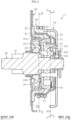
FIG. 2 is a sectional view of a clutch unit according to an embodiment of the present invention. -
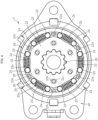
FIG. 3 is a sectional view of a first clutch part of the clutch unit (sectional view taken along the line A-A ofFIG. 2 ) under a state in which an operating lever is in a neutral position. -
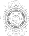
FIG. 4 is a sectional view of a second clutch part of the clutch unit (sectional view taken along the line B-B ofFIG. 2 ) under a state in which the operating lever is in the neutral position. -
FIG. 5 is a sectional view corresponding toFIG. 3 under a state in which the operating lever is operated and a torque is being transmitted. -
FIG. 6 is a sectional view corresponding toFIG. 4 under a state in which the operating lever is operated and a torque is being transmitted. -
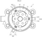
FIG. 7 is a sectional view taken along the line C-C ofFIG. 2 , for illustrating rotation stopping mechanisms for a rotation suppressing member. -
FIG. 8 is a sectional view for illustrating another example of the rotation stopping mechanisms for the rotation suppressing member. -
FIG. 9 is a sectional view for illustrating a still another example of the rotation stopping mechanisms for the rotation suppressing member. -
FIG. 10 is a sectional view of a related-art clutch unit. - Now, an embodiment of the present invention is described with reference to the drawings. In the following embodiment, a clutch unit incorporated into a seat lifter device for an automobile is exemplified. However, the clutch unit according to the present invention is applicable to devices other than a seat lifter device for an automobile.
- In
FIG. 1 , illustration is given of a seat lifter device 60 configured to adjust a seating surface height of aseat 50 of an automobile. The seat lifter device 60 comprises anoperating lever 61, aclutch unit 1, andlink members link members slide member 64 that is provided so as to be slidable in a front-and-rear direction with respect to a vehicle body. Upper ends of thelink members seat 50. Asector gear 65 is formed integrally with the upper end of thelink member 62. Apinion gear part 31 to be meshed with thesector gear 65 is provided to anoutput shaft 30 of theclutch unit 1. - For example, when a seating surface of the
seat 50 is to be lowered, the operatinglever 61 is turned downward. As a result, theoutput shaft 30 of theclutch unit 1 is rotated to pivot thepinion gear part 31 provided to theoutput shaft 30 in a clockwise direction (direction indicated by an arrow ofFIG. 1 ). Then, thesector gear 65, which is meshed with thepinion gear part 31, is turned in a counterclockwise direction (direction indicated by an arrow ofFIG. 1 ) to incline both of thelink members seat 50 is lowered. - When a force for pressing down the operating
lever 61 is released, the operatinglever 61 is turned upward and is returned to its original position (neutral state). A rotational torque generated in this operation is shut off by theclutch unit 1. Thus, theoutput shaft 30 and thepinion gear part 31 are not rotated, and thus a position of the seating surface of theseat 50 is maintained. After that, the seating surface is lowered to a desired position by repeating an operation of pressing down and releasing the operatinglever 61. When the operatinglever 61 is turned upward, the seating surface height of theseat 50 is raised through a reverse operation to the above-mentioned operation. - Further, when a passenger is seated on the
seat 50 and a rotational torque is reversely input to theoutput shaft 30, the reversely input torque is shut off by theclutch unit 1, and thus the seating surface height of theseat 50 is kept. - Now, a structure of the
clutch unit 1 is described in detail. - As illustrated in
FIG. 2 , theclutch unit 1 comprises a firstclutch part 10, a secondclutch part 20, theoutput shaft 30, and ahousing 40. Theoutput shaft 30 is inserted through inner peripheries of the firstclutch part 10 and the secondclutch part 20. Thehousing 40 is a static system that is fixed to the frame of theseat 50. Theoutput shaft 30 is provided so as to be rotatable with respect to thehousing 40. In the following description, an axial center direction of theoutput shaft 30 is referred to as "axial direction", the firstclutch part 10 side (right side ofFIG. 2 ) in the axial direction is referred to as "input side", and the secondclutch part 20 side (left side ofFIG. 2 ) is referred to as "output side". - The first
clutch part 10 is configured to control transmission and shutoff of a rotational torque input from the operating lever 61 (seeFIG. 1 ). The secondclutch part 20 is configured to transmit the rotational torque from the firstclutch part 10 to theoutput shaft 30 and has a reverse-input shutoff function of shutting off a rotational torque that is reversely input from theoutput shaft 30. - As illustrated in
FIG. 2 andFIG. 3 , the firstclutch part 10 comprises aside plate 11, anoperating bracket 12, aninner ring 13, anouter ring 14,cylindrical rollers 15, roller urging springs 16, and a centeringspring 17. Theside plate 11, the operatingbracket 12, and theinner ring 13 correspond to an input rotary body. Theouter ring 14 corresponds to an output rotary body. Thecylindrical rollers 15 correspond to a plurality of engaging elements. Each of the roller urging springs 16 corresponds to an urging member. - As illustrated in
FIG. 2 , an end portion of theoperating bracket 12 is inserted into ahole 11a formed in theside plate 11 and is fixed to theside plate 11 by, for example, caulking. Aprotrusion 13b formed on an input-side end surface of theinner ring 13 is fitted and inserted into ahole 12b formed in theoperating bracket 12. In the above-mentioned manner, theside plate 11, the operatingbracket 12, and theinner ring 13 are integrated. The operating lever 61 (seeFIG. 1 ) is mounted onto theside plate 11. When the operatinglever 61 is operated, theside plate 11, the operatingbracket 12, and theinner ring 13 are rotated together. - An outer periphery of the
inner ring 13 has a plurality ofcam surfaces 13a (seeFIG. 3 ).Wedge gaps 18 are defined between the cam surfaces 13a of theinner ring 13 and an innerperipheral surface 14a of theouter ring 14, which has a cylindrical shape. Each of thewedge gaps 18 has a radial width decreasing toward one side or another side in a circumferential direction. Thecylindrical rollers 15 are arranged between theinner ring 13 and theouter ring 14. The roller urging springs 16 and extendingportions 41 provided in thehousing 40 are arranged alternately in the circumferential direction between thecylindrical rollers 15 adjacent to each other. Each pair ofcylindrical rollers 15 adjacent to each other is urged by theroller urging spring 16 so that thecylindrical rollers 15 are separated apart from each other and are pushed toward smaller width sides of thewedge gap 18 defined between thecam surface 13a of theinner ring 13 and the innerperipheral surface 14a of theouter ring 14. - The centering spring 17 (see
FIG. 2 ) retains the input rotary body comprising theside plate 11 in a neutral position. When the operatinglever 61 is operated to rotate theside plate 11 to one side or another side from the neutral position, theside plate 11 and the centeringspring 17 are engaged with each other and an elastic force is accumulated in the centeringspring 17. When a force applied to the operatinglever 61 is released, the input rotary body comprising theside plate 11 is returned to the neutral position by the elastic force of the centeringspring 17. - As illustrated in
FIG. 2 andFIG. 4 , the secondclutch part 20 comprises arelease bracket 21, anouter ring 22, aninner ring 23, a plurality ofcylindrical rollers 24, and roller urging springs 25. - The
release bracket 21 comprises aflat plate portion 21a and extendingportions 21b (seeFIG. 2 ). Theflat plate portion 21a is fixed to theouter ring 14 of the firstclutch part 10. The extendingportions 21b extend to the output side in the axial direction from a plurality of positions on an outer peripheral edge of theflat plate portion 21a. The extendingportions 21b are arranged between thecylindrical rollers 24 adjacent to each other (at positions where the roller urging springs 25 are not provided) (seeFIG. 4 ). - The
outer ring 22 is fixed to the housing 40 (seeFIG. 2 ). Theinner ring 23 is fixed to an outer periphery of theoutput shaft 30. In the illustrated example, theinner ring 23 and theoutput shaft 30 are fixed by spline fitting (seeFIG. 4 ). An outer periphery of theinner ring 23 has a plurality ofcam surfaces 23a that are arranged equiangularly.Wedge gaps 26 are defined between the cam surfaces 23a of theinner ring 23 and an inner peripheral surface of theouter ring 22, which has a cylindrical shape. Each of thewedge gaps 26 has a radial width decreasing toward one side or another side in the circumferential direction. - The
cylindrical rollers 24 are arranged between theinner ring 23 and theouter ring 22. The roller urging springs 25 are provided between thecylindrical rollers 24 adjacent to each other. Each pair ofcylindrical rollers 24 adjacent to each other is urged by theroller urging spring 25 so that thecylindrical rollers 24 are separated apart from each other and are pushed to smaller width sides of thewedge gap 26 defined between thecam surface 23a of theinner ring 23 and an inner peripheral surface of theouter ring 22. -
Protrusions 23b are formed on an input-side end surface of the inner ring 23 (seeFIG. 2 ). Theprotrusions 23b are inserted intoholes 21c formed in theflat plate portion 21a of therelease bracket 21 so as to each have clearances in the circumferential direction (seeFIG. 4 ). - An operation example of the
clutch unit 1 having the structure described above is now described. - When the operating
lever 61 is pulled up or pushed down, theinner ring 13 is rotated to one side or another side from the neutral position (seeFIG. 3 ). For example, as illustrated inFIG. 5 , when theinner ring 13 is rotated by an angle α in the counterclockwise direction, onecylindrical roller 15, which is on an upstream side in the rotating direction in each pair ofcylindrical rollers 15 adjacent to each other with theroller urging spring 16 interposed therebetween, is engaged with thewedge gap 18 to transmit a rotational torque to theouter ring 14. Meanwhile, anothercylindrical roller 15, which is on a downstream side in the rotating direction in each pair ofcylindrical rollers 15 adjacent to each other with theroller urging spring 16 interposed therebetween, is brought into abutment against the extendingportion 41 of thehousing 40 to restrict its movement in the rotating direction. As a result, thecylindrical roller 15 on the downstream side in the rotating direction is disengaged from thewedge gap 18. Through the operation described above, a rotational torque of theinner ring 13 is transmitted to theouter ring 14 to rotate theinner ring 13 and theouter ring 14 together. At this time, an elastic force is accumulated in the centeringspring 17 along with the rotation of theside plate 11. - When the
outer ring 14 of the firstclutch part 10 is rotated in this manner, therelease bracket 21 of the secondclutch part 20 fixed to theouter ring 14 is rotated along therewith. Then, as illustrated inFIG. 6 , each extendingportion 21b of therelease bracket 21 is brought into abutment against onecylindrical roller 24, which is on the upstream side in the rotating direction in each pair ofcylindrical rollers 24 adjacent to each other with theroller urging spring 25 interposed therebetween, and presses thecylindrical roller 24 in the circumferential direction against an elastic force of theroller urging spring 25. As a result, thecylindrical roller 24 is disengaged from thewedge gap 26. A locked state between theinner ring 23 and theouter ring 22 is released to thereby allow theinner ring 23 and theoutput shaft 30 to rotate. - Then, when the
release bracket 21 is further rotated, the clearance in the rotating direction between theprotrusion 23b of theinner ring 23 and thehole 21c of theflat plate portion 21a of therelease bracket 21 is reduced, and an inner wall of thehole 21c of therelease bracket 21 is brought into abutment against theprotrusion 23b of theinner ring 23 in the rotating direction. As a result, a rotational torque from the firstclutch part 10 is transmitted to theinner ring 23 via therelease bracket 21, and theinner ring 23 and theoutput shaft 30 are rotated together by an angle β. - When the input of the rotational torque by the lever operation is stopped, the input rotary body (the
side plate 11, the operatingbracket 12, and the inner ring 13) of the firstclutch part 10 is returned to the neutral position by the elastic force of the centeringspring 17. At this time, as illustrated inFIG. 5 , thecylindrical rollers 15, which transmit a torque in a returning rotational direction, are disengaged from thewedge gaps 18. Thus, the rotational torque of theinner ring 13 is not transmitted to theouter ring 14, and theouter ring 14 maintains a given rotational position. Accordingly, the rotational torque is not input to the secondclutch part 20, and theoutput shaft 30 maintains its rotational position. - When a pumping operation (vertical reciprocating movement) of the operating lever 61 (see
FIG. 1 ) is performed as described above, theinner ring 13 of the firstclutch part 10 repeats rotational reciprocating movement and theouter ring 14 is inched rotationally. Along with this rotation, theinner ring 23 of the secondclutch part 20 and theoutput shaft 30 are inched rotationally. As a result, the seating surface height of theseat 50 can be adjusted. - In the second
clutch part 20, even when the rotational torque is reversely input to theoutput shaft 30 as a result of seating of a passenger on the seat 50 (seeFIG. 1 ), thecylindrical rollers 24 are engaged with thewedge gaps 26 between theouter ring 22 and theinner ring 23 to thereby lock theinner ring 23 and theoutput shaft 30 with respect to theouter ring 22. In this manner, the rotational torque that is reversely input from theoutput shaft 30 is shut off by the secondclutch part 20, and backflow of the rotational torque, which is reversely input to the firstclutch part 10, is shut off. As a result, the seating surface height of theseat 50 is kept. - The
clutch unit 1 has the overall configuration described above. Arotation suppressing member 70 androtation stopping mechanisms 80, which are characteristic components in the configuration, are now described in detail. - The rotation suppressing member 70 (see
FIG. 2 ) is a member configured to apply rotational resistance to theouter ring 14 of the firstclutch part 10. As therotation suppressing member 70, an urging member that is elastically compressible in the axial direction is used. For example, a wave washer, a disc spring, or a resin ring is used. In this embodiment, a wave washer is used as therotation suppressing member 70. - The
rotation suppressing member 70 is disposed in a compressed state between the operatingbracket 12 and theouter ring 14 of the firstclutch part 10 in the axial direction. An input-side surface of therotation suppressing member 70 is in contact with theoperating bracket 12, and an output-side surface of therotation suppressing member 70 is in contact with theouter ring 14. The output rotary body (theouter ring 14 in the illustrated example) and the input rotary body (theinner ring 13, the operatingbracket 12, and theside plate 11 in the illustrated example) of the firstclutch part 10 are urged so as to be separated apart from each other in the axial direction by an elastic force of therotation suppressing member 70. Movement of the input rotary body to the input side is restricted by abutment of the input rotary body against thehousing 40. A rotary body (integrated body of theouter ring 14 and therelease bracket 21 in the illustrated example) comprising the output rotary body is urged toward the output side with respect to thehousing 40 and is pressed against theinner ring 23 of the secondclutch part 20. - When the operating
lever 61 is returned to the neutral position, as illustrated inFIG. 5 , one of each pair of adjacentcylindrical rollers 15 of the firstclutch part 10 is disengaged from thewedge gap 18 as a result of abutment against the extendingportion 41 of thehousing 40, whereas another one of each pair of thecylindrical rollers 15 is fitted into thewedge gap 18. When theinner ring 13 is rotated in a direction of returning to the neutral position (in the clockwise direction ofFIG. 5 ), the anothercylindrical roller 15 is relatively moved to a larger width side of thewedge gap 18 and thus does not actively contribute to torque transmission to theouter ring 14. However, the anothercylindrical roller 15 is in contact with theinner ring 13 and theouter ring 14. Thus, the rotation of theinner ring 13 in a returning direction may be transmitted to theouter ring 14 via the anothercylindrical roller 15 by frictional forces generated at the contact portions. As a result, theouter ring 14 may be slightly dragged in the returning direction. - To deal with this problem, rotational resistance is applied to the output rotary body (outer ring 14) by the
rotation suppressing member 70 in the above-mentionedclutch unit 1. More specifically, the rotary body (theouter ring 14 and the release bracket 21) comprising theouter ring 14 is pressed against theinner ring 23 of the secondclutch part 20 by the elastic force of the rotation suppressing member 70 (seeFIG. 2 ). When the operatinglever 61 is returned to the neutral position, as illustrated inFIG. 6 , thecylindrical rollers 24, which are not in abutment against the extendingportions 21b of therelease bracket 21, are pushed toward the smaller width sides of thewedge gaps 26 in the secondclutch part 20. Thus, the rotation of theinner ring 23 and thecylindrical rollers 24 in the returning direction is restricted. Accordingly, when the rotary body comprising theouter ring 14 is pressed against theinner ring 23 of the secondclutch part 20 that is restricted from rotating in the returning direction, the rotational resistance is applied to theouter ring 14 by the frictional forces generated at these contact portions. The rotational resistance can prevent the dragging of theouter ring 14, which may be caused along with the rotation of theinner ring 13 of the firstclutch part 10 in the returning direction. - At this time, when the
rotation suppressing member 70 itself is rotated by the frictional force generated at the contact portion with theoperating bracket 12 in the returning direction along with theinner ring 13, the dragging of theouter ring 14 may be caused via therotation suppressing member 70. Thus, theclutch unit 1 comprises therotation stopping mechanisms 80 configured to restrict the rotation of therotation suppressing member 70 with respect to the static system (housing 40) . - As the
rotation stopping mechanisms 80, for example, engaging portions and engaged portions are provided. The engaging portions are provided to thehousing 40. The engaged portions are provided to therotation suppressing member 70 and are configured to be fitted over the engaging portions in the circumferential direction. In this embodiment, as illustrated inFIG. 7 , recessedportions 71 are formed in therotation suppressing member 70 as the engaged portions. More specifically, a plurality of recessedportions 71, each being open at an inner periphery, are formed at a plurality of positions (three positions in the illustrated example) of therotation suppressing member 70 in the circumferential direction. A plurality of engaging portions to be inserted into the recessedportions 71 of therotation suppressing member 70 are provided to thehousing 40. In this embodiment, the extending portions 41 (seeFIG. 2 andFIG. 3 ) of thehousing 40, which are arranged between thecylindrical rollers 15 of the firstclutch part 10, are used as the engaging portions. A circumferential pitch of the recessedportions 71 of therotation suppressing member 70 and a circumferential pitch of the extendingportions 41 of thehousing 40 are equal to each other. In the illustrated example, both of the recessedportions 71 and the extendingportions 41 are formed equiangularly. Each recessedportion 71 and each extendingportion 41 are fitted together with a play in the circumferential direction. When the extendingportions 41 of thehousing 40 are engaged with inner surfaces of the recessedportions 71 of therotation suppressing member 70 in both of the rotating directions, therotation stopping mechanisms 80 configured to restrict the rotation of therotation suppressing member 70 in both of the directions are formed. - As described above, when the recessed portions 71 (engaged portions) of the
rotation suppressing member 70 and the extending portions 41 (engaging portions) of thehousing 40 are engaged with each other in both of the rotating directions, the rotation of therotation suppressing member 70 is restricted in both of the directions. As a result, when the operatinglever 61 is returned to the neutral position, the dragging of theouter ring 14, which may be caused via therotation suppressing member 70 along with the rotation of the input rotary body (theinner ring 13, the operatingbracket 12, and the side plate 11) in the returning direction, can be more reliably prevented. - The present invention is not limited to the above-mentioned embodiment. Now, description is made of other embodiment of the present invention. However, the same points as those in the above-mentioned embodiment are denoted by the same reference symbols, and redundant description thereof is omitted.
- The engaged portions (recessed portions 71) of the
rotation suppressing member 70 and the engaging portions (extending portions 41) of thehousing 40 may be brought into abutment against each other with interferences in the circumferential direction therebetween. For example, as illustrated inFIG. 8 , the extendingportions 41 of thehousing 40 may be press-fitted into the recessedportions 71 of therotation suppressing member 70 in the circumferential direction. In this case, before the assembly of therotation suppressing member 70 and thehousing 40, a width of at least one of the recessedportions 71 of therotation suppressing member 70 in the circumferential direction is slightly smaller than a width of the extendingportion 41 of thehousing 40, which is to be fitted thereinto, in the circumferential direction. As a result, the rotation of therotation suppressing member 70 in both of the directions with respect to thehousing 40 is completely restricted. Thus, the dragging of theouter ring 14 can be reliably restricted. Otherrotation stopping mechanisms 80, each corresponding to the recessedportion 71 and the extendingportion 41 that are fitted together with gaps in the circumferential direction, also function as auxiliary rotation stoppers. However, the auxiliary rotation stoppers may be omitted if not particularly required. Further, inFIG. 8 , the extendingportion 41 is press-fitted into one of the recessedportions 71 among the recessedportions 71 and the extendingportions 41, which are provided at a plurality of positions in the circumferential direction. However, the press-fitting of the extendingportions 41 into the recessedportions 71 is not limited to that described above. The extendingportions 41 may be press-fitted into a plurality of recessed portions 71 (for example, all the recessed portions 71). - In an embodiment illustrated in
FIG. 9 , a circumferential pitch of a plurality of recessed portions (referred to as a first recessedportion 71A, a second recessedportion 71B, and a third recessedportion 71C in this case) formed in therotation suppressing member 70 and a circumferential pitch of a plurality of extending portions (referred to as a first extendingportion 41A, a second extendingportion 41B, and a third extendingportion 41C in this case) of thehousing 40 are set to be different from each other. As a result, the first extendingportion 41A of thehousing 40 is brought into abutment against an inner wall of the first recessedportion 71A of therotation suppressing member 70 on one side in the circumferential direction with an interference (firstrotation stopping mechanism 80A). At the same time, the second extendingportion 41B of thehousing 40 is brought into abutment against an inner wall of the second recessedportion 71B of therotation suppressing member 70 on another side in the circumferential direction with an interference (secondrotation stopping mechanism 80B). Also in this case, the rotation of therotation suppressing member 70 in both directions with respect to thehousing 40 is completely restricted. Thus, the dragging of theouter ring 14 can be reliably restricted. A thirdrotation stopping mechanism 80C, which comprises the third recessedportion 71C and the third extendingportion 41C that are fitted together with gaps defined in the circumferential direction, functions as an auxiliary rotation stopper. However, the thirdrotation stopping mechanism 80C may be omitted if not particularly required. - Further, in a case in which the
rotation suppressing member 70 has two sides that should be distinguished (specifically, the rotation suppressing member should be oriented in a predetermined direction when mounted into the housing 40), it is preferred that the circumferential pitch of the recessedportions 71 and the circumferential pitch of the extendingportions 41 be set so that the recessedportions 71 and the extendingportions 41 are fitted together in a desired state (state illustrated inFIG. 9 ) only when therotation suppressing member 70 is mounted in thehousing 40 while being oriented in the correct direction. As a result, when therotation suppressing member 70 is mounted into thehousing 40 while being oriented in the incorrect direction, the recessedportions 71 and the extendingportions 41 are not fitted together properly. Thus, mounting of therotation suppressing member 70 in the incorrect direction can easily be detected. - A configuration of the
rotation stopping mechanism 80 of therotation suppressing member 70 is not limited to that described above. For example, a recessed portion being open at an outer periphery of therotation suppressing member 70 or a hole passing through therotation suppressing member 70 in the axial direction may be formed as the engaged portion. Further, a protruding portion projecting from therotation suppressing member 70 in a radial direction or the axial direction may be provided as the engaged portion, and a recessed portion configured to be fitted over the protruding portion of therotation suppressing member 70 in the circumferential direction may be formed in thehousing 40 as the engaging portion. Alternatively, a rotation stopping mechanism may be formed by fixing therotation suppressing member 70 and thehousing 40 together through, for example, welding or screwing. - The
rotation suppressing member 70 is only required to be disposed between the input rotary body and the output rotary body of the firstclutch part 10 in the axial direction so as to be in contact with the input rotary body and the output rotary body. For example, therotation suppressing member 70 may be disposed between theinner ring 13 and theouter ring 14 in the axial direction or between theside plate 11 and theouter ring 14 in the axial direction so as to be in contact therewith. - In the embodiment described above, the first clutch part has been described as a constant mesh-type clutch in which the
cylindrical rollers 15 are pushed to the smaller width sides of thewedge gaps 18 by the roller urging springs 16. However, the first clutch part is not limited to the above-mentioned clutch. For example, the first clutch part may bring the engaging elements into an unengaged state with the inner ring and the outer ring when the operating lever is in the neutral position and pushes the engaging elements to the smaller width sides of the wedge gaps to allow transmission of a torque between the inner ring and the outer ring when the operating lever is operated. - Further, in the embodiment described above, the first clutch part having the inner ring as the input rotary body and the outer ring as the output rotary body has been described. However, the inner ring and the outer ring are interchangeable. The first clutch may have the inner ring as the output rotary body and the outer ring as the input rotary body.
-
- 1
- clutch unit
- 10
- first clutch part
- 11
- side plate (input rotary body)
- 12
- operating bracket (input rotary body)
- 13
- inner ring (input rotary body)
- 14
- outer ring (output rotary body)
- 15
- cylindrical roller (engaging element)
- 16
- roller urging spring (urging member)
- 20
- second clutch part
- 21
- release bracket
- 22
- outer ring
- 23
- inner ring
- 25
- roller urging spring
- 30
- output shaft
- 40
- housing (static system)
- 41
- extending portion (engaging portion)
- 50
- seat
- 60
- seat lifter device
- 61
- operating lever
- 70
- rotation suppressing member
- 71
- recessed portions (engaged portion)
- 80
- rotation stopping mechanism
Claims (5)
- A clutch unit, comprising:a static system;an output shaft configured to be rotatable with respect to the static system;a first clutch part, which comprises an input rotary body, an output rotary body, and a plurality of engaging elements disposed between the input rotary body and the output rotary body, and is configured to transmit a rotational torque, which is generated when the input rotary body is rotated from a neutral position, to the output rotary body and shut off a rotational torque, which is generated when the input rotary body is returned to the neutral position;a second clutch part configured to transmit a rotational torque of the output rotary body of the first clutch part to the output shaft and shut off a rotational torque from the output shaft to the output rotary body of the first clutch part;a rotation suppressing member configured to apply rotational resistance to the output rotary body; anda rotation stopping mechanism configured to restrict rotation of the rotation suppressing member with respect to the static system.
- The clutch unit according to claim 1, wherein the rotation stopping mechanism comprises:an engaging portion provided to the static system; andan engaged portion, which is provided to the rotation suppressing member, and is configured to be fitted over the engaging portion in a circumferential direction.
- The clutch unit according to claim 2, wherein the engaging portion and the engaged portion are brought into abutment against each other with an interference in a circumferential direction therebetween.
- The clutch unit according to claim 1,
wherein the rotation stopping mechanism comprises:a plurality of engaging portions provided to the static system; anda plurality of engaged portions, which are provided to the rotation suppressing member, and are configured to be fitted over the plurality of engaging portions in a circumferential direction, andwherein a circumferential pitch of the plurality of engaging portions and a circumferential pitch of the plurality of engaged portions are set to be different from each other. - The clutch unit according to any one of claims 1 to 4, wherein the first clutch part comprises:a wedge gap defined between the input rotary body and the output rotary body; andan urging member configured to urge the engaging elements toward smaller width sides of the wedge gap.
Applications Claiming Priority (2)
| Application Number | Priority Date | Filing Date | Title |
|---|---|---|---|
| JP2020210345A JP2022097009A (en) | 2020-12-18 | 2020-12-18 | Clutch unit |
| PCT/JP2021/045591 WO2022131162A1 (en) | 2020-12-18 | 2021-12-10 | Clutch unit |
Publications (1)
| Publication Number | Publication Date |
|---|---|
| EP4265932A1 true EP4265932A1 (en) | 2023-10-25 |
Family
ID=82057781
Family Applications (1)
| Application Number | Title | Priority Date | Filing Date |
|---|---|---|---|
| EP21906524.0A Withdrawn EP4265932A1 (en) | 2020-12-18 | 2021-12-10 | Clutch unit |
Country Status (4)
| Country | Link |
|---|---|
| US (1) | US20240102519A1 (en) |
| EP (1) | EP4265932A1 (en) |
| JP (1) | JP2022097009A (en) |
| WO (1) | WO2022131162A1 (en) |
Family Cites Families (3)
| Publication number | Priority date | Publication date | Assignee | Title |
|---|---|---|---|---|
| JP6754634B2 (en) * | 2015-12-18 | 2020-09-16 | シロキ工業株式会社 | Vehicle clutch unit |
| JP6745188B2 (en) * | 2016-10-07 | 2020-08-26 | シロキ工業株式会社 | Vehicle clutch unit |
| JP6970642B2 (en) * | 2018-05-31 | 2021-11-24 | シロキ工業株式会社 | Vehicle clutch unit |
-
2020
- 2020-12-18 JP JP2020210345A patent/JP2022097009A/en active Pending
-
2021
- 2021-12-10 WO PCT/JP2021/045591 patent/WO2022131162A1/en not_active Ceased
- 2021-12-10 EP EP21906524.0A patent/EP4265932A1/en not_active Withdrawn
- 2021-12-10 US US18/019,656 patent/US20240102519A1/en not_active Abandoned
Also Published As
| Publication number | Publication date |
|---|---|
| WO2022131162A1 (en) | 2022-06-23 |
| US20240102519A1 (en) | 2024-03-28 |
| JP2022097009A (en) | 2022-06-30 |
Similar Documents
| Publication | Publication Date | Title |
|---|---|---|
| US10800294B2 (en) | Clutch unit | |
| EP2840275B1 (en) | Clutch unit | |
| US8424665B2 (en) | Clutch unit | |
| CN108603545B (en) | Clutch unit | |
| EP3434924B1 (en) | Clutch unit | |
| US8985296B2 (en) | Clutch unit | |
| US8678155B2 (en) | Clutch unit | |
| US20190210490A1 (en) | Clutch unit | |
| CN108430826B (en) | clutch unit for vehicle | |
| US20240102519A1 (en) | Clutch unit | |
| JP7336907B2 (en) | clutch unit | |
| US11434962B2 (en) | Clutch unit | |
| JP7152869B2 (en) | clutch unit | |
| JP2018004008A (en) | Clutch unit | |
| JP7403360B2 (en) | clutch unit | |
| WO2017150401A1 (en) | Clutch unit | |
| WO2019059141A1 (en) | Clutch unit | |
| JP2024110195A (en) | Clutch unit | |
| JP2018119647A (en) | Clutch unit | |
| JP2025064510A (en) | Clutch unit | |
| WO2026034081A1 (en) | Clutch unit | |
| JP2022128823A (en) | clutch unit | |
| JP2024089052A (en) | Reverse input cutoff clutch | |
| JP2022085370A (en) | Clutch unit | |
| JP2021001654A (en) | Clutch unit |
Legal Events
| Date | Code | Title | Description |
|---|---|---|---|
| STAA | Information on the status of an ep patent application or granted ep patent |
Free format text: STATUS: THE INTERNATIONAL PUBLICATION HAS BEEN MADE |
|
| PUAI | Public reference made under article 153(3) epc to a published international application that has entered the european phase |
Free format text: ORIGINAL CODE: 0009012 |
|
| STAA | Information on the status of an ep patent application or granted ep patent |
Free format text: STATUS: REQUEST FOR EXAMINATION WAS MADE |
|
| 17P | Request for examination filed |
Effective date: 20230210 |
|
| AK | Designated contracting states |
Kind code of ref document: A1 Designated state(s): AL AT BE BG CH CY CZ DE DK EE ES FI FR GB GR HR HU IE IS IT LI LT LU LV MC MK MT NL NO PL PT RO RS SE SI SK SM TR |
|
| DAV | Request for validation of the european patent (deleted) | ||
| DAX | Request for extension of the european patent (deleted) | ||
| STAA | Information on the status of an ep patent application or granted ep patent |
Free format text: STATUS: THE APPLICATION HAS BEEN WITHDRAWN |
|
| 18W | Application withdrawn |
Effective date: 20240524 |