WO2019059141A1 - Clutch unit - Google Patents
Clutch unit Download PDFInfo
- Publication number
- WO2019059141A1 WO2019059141A1 PCT/JP2018/034308 JP2018034308W WO2019059141A1 WO 2019059141 A1 WO2019059141 A1 WO 2019059141A1 JP 2018034308 W JP2018034308 W JP 2018034308W WO 2019059141 A1 WO2019059141 A1 WO 2019059141A1
- Authority
- WO
- WIPO (PCT)
- Prior art keywords
- rotational torque
- output
- output shaft
- input
- side clutch
- Prior art date
Links
Images


Classifications
-
- B—PERFORMING OPERATIONS; TRANSPORTING
- B60—VEHICLES IN GENERAL
- B60N—SEATS SPECIALLY ADAPTED FOR VEHICLES; VEHICLE PASSENGER ACCOMMODATION NOT OTHERWISE PROVIDED FOR
- B60N2/00—Seats specially adapted for vehicles; Arrangement or mounting of seats in vehicles
- B60N2/02—Seats specially adapted for vehicles; Arrangement or mounting of seats in vehicles the seat or part thereof being movable, e.g. adjustable
- B60N2/04—Seats specially adapted for vehicles; Arrangement or mounting of seats in vehicles the seat or part thereof being movable, e.g. adjustable the whole seat being movable
- B60N2/16—Seats specially adapted for vehicles; Arrangement or mounting of seats in vehicles the seat or part thereof being movable, e.g. adjustable the whole seat being movable height-adjustable
-
- B—PERFORMING OPERATIONS; TRANSPORTING
- B60—VEHICLES IN GENERAL
- B60N—SEATS SPECIALLY ADAPTED FOR VEHICLES; VEHICLE PASSENGER ACCOMMODATION NOT OTHERWISE PROVIDED FOR
- B60N2/00—Seats specially adapted for vehicles; Arrangement or mounting of seats in vehicles
- B60N2/90—Details or parts not otherwise provided for
-
- F—MECHANICAL ENGINEERING; LIGHTING; HEATING; WEAPONS; BLASTING
- F16—ENGINEERING ELEMENTS AND UNITS; GENERAL MEASURES FOR PRODUCING AND MAINTAINING EFFECTIVE FUNCTIONING OF MACHINES OR INSTALLATIONS; THERMAL INSULATION IN GENERAL
- F16D—COUPLINGS FOR TRANSMITTING ROTATION; CLUTCHES; BRAKES
- F16D15/00—Clutches with wedging balls or rollers or with other wedgeable separate clutching members
-
- F—MECHANICAL ENGINEERING; LIGHTING; HEATING; WEAPONS; BLASTING
- F16—ENGINEERING ELEMENTS AND UNITS; GENERAL MEASURES FOR PRODUCING AND MAINTAINING EFFECTIVE FUNCTIONING OF MACHINES OR INSTALLATIONS; THERMAL INSULATION IN GENERAL
- F16D—COUPLINGS FOR TRANSMITTING ROTATION; CLUTCHES; BRAKES
- F16D41/00—Freewheels or freewheel clutches
- F16D41/06—Freewheels or freewheel clutches with intermediate wedging coupling members between an inner and an outer surface
- F16D41/064—Freewheels or freewheel clutches with intermediate wedging coupling members between an inner and an outer surface the intermediate members wedging by rolling and having a circular cross-section, e.g. balls
- F16D41/066—Freewheels or freewheel clutches with intermediate wedging coupling members between an inner and an outer surface the intermediate members wedging by rolling and having a circular cross-section, e.g. balls all members having the same size and only one of the two surfaces being cylindrical
- F16D41/067—Freewheels or freewheel clutches with intermediate wedging coupling members between an inner and an outer surface the intermediate members wedging by rolling and having a circular cross-section, e.g. balls all members having the same size and only one of the two surfaces being cylindrical and the members being distributed by a separate cage encircling the axis of rotation
-
- F—MECHANICAL ENGINEERING; LIGHTING; HEATING; WEAPONS; BLASTING
- F16—ENGINEERING ELEMENTS AND UNITS; GENERAL MEASURES FOR PRODUCING AND MAINTAINING EFFECTIVE FUNCTIONING OF MACHINES OR INSTALLATIONS; THERMAL INSULATION IN GENERAL
- F16D—COUPLINGS FOR TRANSMITTING ROTATION; CLUTCHES; BRAKES
- F16D41/00—Freewheels or freewheel clutches
- F16D41/06—Freewheels or freewheel clutches with intermediate wedging coupling members between an inner and an outer surface
- F16D41/08—Freewheels or freewheel clutches with intermediate wedging coupling members between an inner and an outer surface with provision for altering the freewheeling action
- F16D41/10—Freewheels or freewheel clutches with intermediate wedging coupling members between an inner and an outer surface with provision for altering the freewheeling action with self-actuated reversing
Definitions
- the present invention is provided with an input-side clutch portion to which a rotational torque is input, and an output-side clutch portion for transmitting the rotational torque from the input-side clutch portion to the output side and blocking the rotational torque from the output side. It relates to a clutch unit.
- a clutch portion is disposed between an input member and an output member.
- the clutch unit is configured to control transmission and interruption of rotational torque by engaging and disengaging an engager between the input member and the output member.
- the clutch unit disclosed in Patent Document 1 transmits to the output side the rotational torque from the lever side clutch portion to which the rotational torque is input by the lever operation and the rotational torque from the lever side clutch portion, and also transmits the rotational torque from the output side. And a brake-side clutch unit that shuts off.
- the lever side clutch portion engages and disengages the outer ring to which the rotational torque is input by the lever operation, the inner ring transmitting the rotational torque input from the outer ring to the brake side clutch portion, and the clearance between the outer ring and the inner ring
- the main part is constituted by the cylindrical roller which controls transmission and interception of the rotational torque from an outer ring by this.
- the brake-side clutch portion includes an inner ring to which rotational torque from the lever-side clutch portion is input, an output shaft to which rotational torque from the inner ring is output, an outer ring whose rotation is constrained, a gap between the output shaft and the outer ring
- the main part is constituted by cylindrical rollers which control the interruption of the rotational torque from the output shaft and the transmission of the rotational torque from the inner ring by the engagement and disengagement of the clearances.
- Patent No. 5207779 gazette
- the present invention has been proposed in view of the problems described above, and the purpose of the present invention is to securely lock the output shaft even if the rotational torque in the forward and reverse directions is continuously reversely input to the output shaft. It is providing the clutch unit provided with the structure obtained.
- the clutch unit according to the present invention transmits to the output side the rotational torque from the input-side clutch portion that controls transmission and interruption of the input rotational torque, and the input-side clutch portion, and is reversely input from the output side It has a basic configuration including an output side clutch unit that shuts off the rotational torque.
- the output-side clutch unit of the present invention includes a stationary member whose rotation is restricted, and an output member whose rotational output is output, and an output member when rotational torque is interrupted.
- a gear member is engaged with the stationary member, and the gear member has a module size of 0.4 to 0.8 and a gear number of 60 to 100. It is characterized by having a tooth portion defined in pieces.
- the stationary member by attaching the gear member to the stationary member, when the output member is locked, even if the rotational torque in the forward direction and the rotational torque in the reverse direction are alternately continued and continuously input to the output member, the stationary member
- the gear member attached to the gear is engaged with the output member, whereby the output member can be reliably locked.
- the gear member in the present invention has a toothed part having a module of 0.4 to 0.8 and a tooth number of 60 to 100, so that the gear member meshes with the output member at the time of interruption of the rotational torque. Good operability can be ensured in releasing the meshing state with the output member at the time of transmission of torque.
- the output side clutch portion is configured to interrupt the rotational torque reversely input from the output member and transmit the rotational torque input from the input side clutch portion by engagement and disengagement between the stationary member and the output member.
- the input-side clutch portion and the output-side clutch portion in the present invention preferably have a structure incorporated in a seat lifter portion for a vehicle.
- the gear member by providing the gear member to the stationary member, when the output member is locked, even if the rotational torque in the forward direction and the rotational torque in the reverse direction are alternately continued and continuously input to the output member, Since the gear member attached to the stationary member is in mesh with the output member, the output member can be reliably locked.
- the gear member has a tooth portion whose module is 0.4 to 0.8 and the number of teeth is 60 to 100. Therefore, the gear member meshes with the output member at the time of blocking the rotational torque, and the rotational torque is transmitted Sometimes when releasing the meshing state with the output member, good operability can be ensured.
- the clutch unit when the clutch unit is incorporated into a seat lifter for a car, the height of the seat can be stably adjusted, and the comfortable adjustment of the seat height becomes possible, thus improving operability. It can be done.
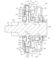
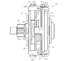
- FIG. 1 is a cross-sectional view showing an entire configuration of a clutch unit according to an embodiment of the present invention.
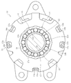
- FIG. 2 is a cross-sectional view taken along the line PP of FIG. 1;
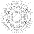
- FIG. 2 is a cross-sectional view taken along the line QQ in FIG.
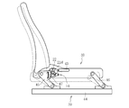
- It is a block diagram which shows the seat of a motor vehicle, and a seat lifter part.
- FIG. 6 is an exploded perspective view showing a slide gear, an elastic member and a side plate in the clutch unit of FIG. 1; It is the side view which looked at the slide gear of FIG. 5 from the input side.
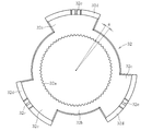
- It is a top view which shows the clutch unit of FIG.
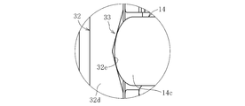
- It is an enlarged view which shows the X section of FIG.
- It is sectional drawing which shows the operation state of the clutch unit of FIG.
- FIG. 1 is a cross-sectional view showing the entire configuration of the clutch unit
- FIG. 2 is a cross-sectional view taken along the line PP in FIG. 1
- FIG. 3 is a cross-sectional view taken along the line QQ in FIG.
- the clutch unit 10 of this embodiment has a structure in which a lever side clutch portion 11 as an input side clutch portion and a brake side clutch portion 12 as an output side clutch portion are unitized.
- the lever side clutch unit 11 controls transmission and interruption of rotational torque input by lever operation.
- the brake side clutch unit 12 has a reverse input blocking function of transmitting the rotational torque from the lever side clutch unit 11 to the output side and blocking the rotational torque reversely input from the output side.
- the lever-side clutch portion 11 includes the side plate 13 and the outer ring 14, the inner ring 15, a plurality of cylindrical rollers 16, a cage 17, an inner centering spring 18, and an outer centering spring 19. And the main part is composed.
- the side plate 13 and the outer ring 14 are integrated by fitting the claws 13a formed on the outer peripheral edge of the side plate 13 into the notched concave portions 14a formed on the outer peripheral edge of the outer ring 14, and caulking The rotational torque is input by the operation.
- a plurality of cam surfaces 14 b are formed on the inner periphery of the outer ring 14 at equal intervals in the circumferential direction.
- the rotational torque is input to the outer ring 14 by an operation lever 43 (see FIG. 4) attached to the side plate 13 by screwing or the like.
- the inner ring 15 has a cylindrical portion 15a through which the output shaft 22 is inserted, an enlarged diameter portion 15b in which a brake side end of the cylindrical portion 15a extends radially outward, and an outer peripheral end of the enlarged diameter portion 15b. It consists of a plurality of column parts 15c (refer to Drawing 3) which projected by bending a part in the direction of an axis.
- the inner ring 15 transmits the rotational torque input from the outer ring 14 to the brake clutch portion 12.
- a weir 20 is formed between the cylindrical outer peripheral surface 15 d of the cylindrical portion 15 a of the inner ring 15 and the cam surface 14 b formed on the inner periphery of the outer ring 14.
- the cylindrical rollers 16 transmit and block the rotational torque from the outer ring 14 by engagement and disengagement at the wedging gap 20 formed between the cam surface 14 b of the outer ring 14 and the outer peripheral surface 15 d of the cylindrical portion 15 a of the inner ring 15. Control.
- a plurality of pockets 17 a for accommodating the cylindrical rollers 16 are formed at equal intervals in the circumferential direction.
- the cylindrical roller 16 is held at equal intervals in the circumferential direction by the cage gap 20 between the cam surface 14 b of the outer ring 14 and the outer peripheral surface 15 d of the cylindrical portion 15 a of the inner ring 15 by the cage 17.
- the inner centering spring 18 is a C-shaped elastic member having a circular cross section and disposed between the retainer 17 and the cover 24 of the brake-side clutch portion 12, and both ends thereof are a part of the retainer 17 and the cover 24. It is locked.
- the outer centering spring 19 located radially outward of the inner centering spring 18 is a C-shaped band plate elastic member disposed between the outer ring 14 and the above-mentioned cover 24, and both ends thereof are the outer ring 14 and the cover 24. It is locked to a part of
- the brake clutch portion 12 includes the inner ring 15 of the lever clutch portion 11, the output shaft 22 which is an output member, the outer ring 23 which is a stationary member, the cover 24 and the side plate 25;
- a main portion is constituted by a plurality of pairs of engaging elements, a cylindrical roller 27 and a plate spring 28 having an N-shaped cross section, and a friction ring 29.
- the output shaft 22 has a shaft portion 22a on which the cylindrical portion 15a of the inner ring 15 is extrapolated, a large diameter portion 22b integrally formed substantially at the center of the shaft portion 22a, and an output side end of the shaft portion 22a It consists of a pinion gear portion 22d coaxially formed in the portion, and the rotational torque from the lever side clutch portion 11 is output.
- the pinion gear portion 22d of the output shaft 22 is connected to the seat lifter portion 39 (see FIG. 4).
- the components of the lever side clutch unit 11 are prevented from coming off by press-fitting the washer 31 to the input side end of the shaft portion 22 a of the output shaft 22 via the wave washer 30.
- a plurality of flat cam surfaces 22 e are formed at equal intervals in the circumferential direction on the outer periphery of the large diameter portion 22 b of the output shaft 22. Between the cam surface 22e of the large diameter portion 22b and the cylindrical inner peripheral surface 23a of the outer ring 23, a wedging gap 26 is formed.
- Two cylindrical rollers 27 and one plate spring 28 interposed therebetween are disposed in the wedging gap 26 respectively.
- the cylindrical roller 27 controls the blocking of the rotational torque reversely input from the output shaft 22 and the transmission of the rotational torque input from the inner ring 15 by engagement and disengagement at the weir clearance 26.
- the leaf spring 28 biases the cylindrical rollers 27 against each other in the circumferential direction.
- the cylindrical rollers 27 and the plate springs 28 are disposed at equal intervals in the circumferential direction by the column portions 15 c of the inner ring 15 having a function of transmitting the rotational torque input from the outer ring 14 to the output shaft 22. That is, the column portion 15c of the inner ring 15 has a function of accommodating the cylindrical roller 27 and the plate spring 28 in the pocket 15f and maintaining the same in the circumferential direction.
- the large diameter portion 22 b of the output shaft 22 is provided with a projection 22 f for transmitting the rotational torque from the inner ring 15 to the output shaft 22.
- the projection 22 f is inserted and arranged in a hole 15 e formed in the enlarged diameter portion 15 b of the inner ring 15 with a clearance in the circumferential direction.
- the outer ring 23, the cover 24, and the side plate 25 are provided in the notch recess 23b formed on the outer peripheral edge of the outer ring 23, and the notch recess (not shown) formed on the outer peripheral edge of the cover 24.
- the claws 25a formed on the outer peripheral edge are integrated and integrated by fitting and caulking.
- the friction ring 29 is a member made of resin, for example, and is fixed to the side plate 25.
- the friction ring 29 is press-fitted to the inner peripheral surface 22g of the annular recess 22c formed in the large diameter portion 22b of the output shaft 22 with a fitting margin.
- a rotational resistance (sliding torque) is applied to the reference numeral 22.
- lever side clutch part 11 and the brake side clutch part 12 which comprise the above structures is demonstrated below.
- the cylindrical roller 27 separates from the weir clearance 26.
- the locked state of the output shaft 22 is released and the output shaft 22 becomes rotatable.
- the friction ring 29 applies a rotational resistance to the output shaft 22.
- FIG. 4 shows a seat 40 mounted in the passenger compartment of a motor vehicle.
- the seating surface height of the seat 40 in the seat lifter 39 is adjusted by the operation lever 43 attached to the side plate 13 (see FIG. 1) of the lever side clutch 11 in the clutch unit 10.
- the seat lifter unit 39 has the following structure.
- each of the link members 45 and 46 is pivotably connected to the slide movable member 44.
- the other ends of the link members 45 and 46 are pivotably attached to the seat 40 respectively.
- a sector gear 47 is integrally provided at the other end of the link member 45.
- the sector gear 47 meshes with the pinion gear portion 22 d of the output shaft 22 of the clutch unit 10.
- the pinion gear portion 22d of the output shaft 22 of the brake clutch portion 12 rotates clockwise (FIG. 4) by the rotational torque transmitted from the lever clutch portion 11 to the brake clutch portion 12 when the brake clutch portion 12 is unlocked. In the direction of the arrow).
- the sector gear 47 meshing with the pinion gear portion 22d pivots counterclockwise (in the direction of the arrow in FIG. 4), and the link member 45 and the link member 46 both tilt to lower the seat surface of the seat 40 become.
- the overall configuration of the clutch unit 10 in this embodiment is as described above, and its characteristic configuration will be described in detail below.
- the clutch unit 10 of this embodiment has the following structure in order to reliably lock the output shaft 22 even if the rotational torque in the forward and reverse directions as described above is continuously reversely input to the output shaft 22.
- the brake-side clutch portion 12 is a gear member that meshes with the output shaft 22 at the time of blocking the rotational torque, and is disengaged from the output shaft 22 at the time of transmitting the rotational torque.
- a structure in which the gear 32 is attached to the outer ring 23 is provided.
- the slide gear 32 is arranged to be movable in the axial direction with respect to the output shaft 22.
- the slide gear 32 has a ring-shaped main body 32b having teeth portions 32a (hereinafter referred to as internal teeth) formed on the inner periphery thereof, and a plurality of circumferential positions (3 points in FIG. 5) on the outer periphery of the ring-shaped main body 32b.
- the flange portion 32c extends radially outward at equal intervals, and the flange portion 32d axially extends from the flange portion 32c.
- the number of teeth of the internal teeth 32a of the slide gear 32 is set to 60 to 100. That is, as shown in FIG. 6, the central angle ⁇ per tooth of the internal teeth 32a of the slide gear 32 is set to 3.6 ° or more and 6 ° or less. Table 1 shows the correspondence between the number of teeth and the central angle per tooth.
- the module is set to 0.4 to 0.8 for the internal teeth 32a of the slide gear 32.
- the module is the pitch circle diameter divided by the number of teeth.
- Table 2 shows the relationship between the number of teeth and the module.
- the numerical range of the module for the internal teeth 32a of the slide gear 32 it is possible to easily secure the tooth thickness of the internal teeth 32a, and to ensure good operability and sufficient strength.
- the internal teeth 32a can be realized. Further, by defining the numerical range of the module as described above, a large torque load can be achieved, and the number of cylindrical rollers can be reduced.
- the number of teeth is 60
- the module is 0.6, 0.8
- the number of teeth is 70
- the module is 0.5, 0.6
- the number of teeth It was found that 80 modules with 0.5, 0.6, 90 teeth, 0.4, 0.5 with module, 100 teeth with 0.4 with 0.4 module are effective. .
- the central angle ⁇ per tooth is set to about 5 °, the number of teeth to 70, and the module to 0.5.
- a tooth portion 22 h (hereinafter referred to as an external tooth) corresponding to the internal tooth 32 a of the slide gear 32 is formed.
- a recess 23c corresponding to the flange portion 32c of the slide gear 32 is formed on the end face of the outer ring 23 . Furthermore, on the outer peripheral surface of the outer ring 23, a recess 23d corresponding to the flange portion 32d of the slide gear 32 is formed.
- the slide gear 32 is assembled to the outer ring 23 by housing the flange portion 32 c in the recess 23 c of the end face of the outer ring 23 and fitting the flange portion 32 d into the recess 23 d of the outer peripheral surface of the outer ring 23.
- a cam mechanism 33 for moving the slide gear 32 in the axial direction to control engagement and disengagement with the output shaft 22 is interposed between the slide gear 32 and the outer ring 14 of the lever side clutch portion 11.
- the cam mechanism 33 has a V-shaped cam groove 32 e formed on the end face of the flange portion 32 d of the slide gear 32 and an outer periphery of the outer ring 14 of the lever side clutch portion 11. It is comprised by the convex part 14c extended to direction.
- the tip bent portion of the convex portion 14 c of the outer ring 14 is in contact with the cam surface of the cam groove 32 e of the slide gear 32.
- an elastic member 34 elastically urging the slide gear 32 in the direction of meshing with the output shaft 22 between the side plate 25 of the brake clutch 12 and the slide gear 32. Intervenes.
- the elastic member 34 for example, a ring-shaped wave spring as shown in FIG.
- the outer ring 14 is maintained in the neutral state by the outer centering spring 19 in the state where the rotational torque is not input from the outer ring 14 of the lever side clutch portion 11.
- the slide gear 32 is axially pressed by the elastic force of the elastic member 34, and the internal teeth 32a of the slide gear 32 mesh with the external teeth 22h of the output shaft 22 (see FIG. 1). As a result, the output shaft 22 is locked.
- the contact position of the cylindrical roller 27 is slightly shifted between the outer ring 23 and the output shaft 22, or hysteresis of elastic deformation exists in the output shaft 22, the outer ring 23, and the cylindrical roller 27 on which the rotational torque is loaded
- the meshing between the internal teeth 32a of the slide gear 32 and the external teeth 22h of the output shaft 22 can prevent the output shaft 22 from rotating gradually. As a result, it is possible to prevent the occurrence of a phenomenon in which the seat 40 slightly drops.
- the meshing of the internal teeth 32 a of the slide gear 32 and the external teeth 22 h of the output shaft 22 enables a large capacity torque load on the brake clutch portion 12.
- the number of pairs of cylindrical rollers 27 constituting the brake-side clutch unit 12 can be reduced, and the weight and cost of the clutch unit 10 can be reduced.
- six pairs of cylindrical rollers 27 are used, but the present invention is not limited thereto.
- the present invention is not limited thereto.
- the number of teeth is 70 and the module is 0.5, the number of teeth is five, Sufficient strength can be ensured even if the number of cylindrical rollers 27 is reduced, such as 4 pairs for 60 modules and 0.6 for 70 pairs of teeth with 70 teeth and 0.6 modules. it can.
- an elastic member 34 is interposed between the side plate 25 of the brake clutch 12 and the slide gear 32 to elastically bias the slide gear 32 in the direction of meshing with the output shaft 22. doing.
- the axial movement of the slide gear 32 separates the internal teeth 32a of the slide gear 32 from the external teeth 22h of the output shaft 22, and the engagement between the internal teeth 32a of the slide gear 32 and the external teeth 22h of the output shaft 22 is released. Be done. As a result, the output shaft 22 becomes rotatable with respect to the outer ring 23.
- the engagement of the cylindrical roller 27 is the inner ring until the internal teeth 32a of the slide gear 32 completely separate from the external teeth 22h of the output shaft 22 and the output shaft 22 becomes rotatable. It is necessary to prevent release by 15.
- the cylindrical roller 27 has a gap 26 between the outer ring 23 and the output shaft 22. It also requires a structure to engage with the
Abstract
The present invention comprises: a lever-side clutch part that controls the transmission and stoppage of rotational torque inputted by lever operation; and a brake-side clutch part that transmits the rotational torque from the lever-side clutch part to the output side and stops rotational torque inputted in reverse from the output side. The brake-side clutch part is provided with an outer ring, the rotation of which is restricted, and an output shaft from which the rotation is outputted, and attaches, to the outer ring, a slide gear 32 that engages with the output shaft while the rotational torque is stopped, and disengages from the output shaft when the rotational torque is being transmitted. The slide gear 32 has a module of 0.4-0.8 and has inner teeth 32a that are restricted to 60-100 in number.
Description
本発明は、回転トルクが入力される入力側クラッチ部と、その入力側クラッチ部からの回転トルクを出力側へ伝達すると共に、出力側からの回転トルクを遮断する出力側クラッチ部とを備えたクラッチユニットに関する。
The present invention is provided with an input-side clutch portion to which a rotational torque is input, and an output-side clutch portion for transmitting the rotational torque from the input-side clutch portion to the output side and blocking the rotational torque from the output side. It relates to a clutch unit.
円筒ころやボール等の係合子を用いるクラッチユニットにおいては、入力部材と出力部材との間にクラッチ部が配設される。クラッチ部は、入力部材と出力部材との間で係合子を係合および離脱させることによって、回転トルクの伝達および遮断を制御する構成になっている。
In a clutch unit using an engaging element such as a cylindrical roller or a ball, a clutch portion is disposed between an input member and an output member. The clutch unit is configured to control transmission and interruption of rotational torque by engaging and disengaging an engager between the input member and the output member.
本出願人は、レバー操作により座席シートを上下調整する自動車用シートリフタ部に組み込まれるクラッチユニットを先に提案している(例えば、特許文献1参照)。
The applicant has previously proposed a clutch unit incorporated in a seat lifter portion for a motor vehicle, which vertically adjusts a seat by a lever operation (see, for example, Patent Document 1).
特許文献1に開示されたクラッチユニットは、レバー操作により回転トルクが入力されるレバー側クラッチ部と、そのレバー側クラッチ部からの回転トルクを出力側へ伝達すると共に、出力側からの回転トルクを遮断するブレーキ側クラッチ部とを備えている。
The clutch unit disclosed in Patent Document 1 transmits to the output side the rotational torque from the lever side clutch portion to which the rotational torque is input by the lever operation and the rotational torque from the lever side clutch portion, and also transmits the rotational torque from the output side. And a brake-side clutch unit that shuts off.
レバー側クラッチ部は、レバー操作により回転トルクが入力される外輪と、その外輪から入力される回転トルクをブレーキ側クラッチ部に伝達する内輪と、外輪と内輪間の楔すきまでの係合および離脱により外輪からの回転トルクの伝達および遮断を制御する円筒ころとで主要部が構成されている。
The lever side clutch portion engages and disengages the outer ring to which the rotational torque is input by the lever operation, the inner ring transmitting the rotational torque input from the outer ring to the brake side clutch portion, and the clearance between the outer ring and the inner ring The main part is constituted by the cylindrical roller which controls transmission and interception of the rotational torque from an outer ring by this.
ブレーキ側クラッチ部は、レバー側クラッチ部からの回転トルクが入力される内輪と、その内輪からの回転トルクが出力される出力軸と、回転が拘束された外輪と、出力軸と外輪間の楔すきまでの係合および離脱により出力軸からの回転トルクの遮断と内輪からの回転トルクの伝達とを制御する円筒ころとで主要部が構成されている。
The brake-side clutch portion includes an inner ring to which rotational torque from the lever-side clutch portion is input, an output shaft to which rotational torque from the inner ring is output, an outer ring whose rotation is constrained, a gap between the output shaft and the outer ring The main part is constituted by cylindrical rollers which control the interruption of the rotational torque from the output shaft and the transmission of the rotational torque from the inner ring by the engagement and disengagement of the clearances.
レバー側クラッチ部では、レバー操作により外輪に回転トルクが入力されると、円筒ころが外輪と内輪間の楔すきまに係合する。この楔すきまでの円筒ころの係合により、内輪に回転トルクが伝達されて内輪が回転する。
In the lever side clutch portion, when rotational torque is input to the outer ring by the lever operation, the cylindrical rollers engage with the gap between the outer ring and the inner ring. Due to the engagement of the cylindrical rollers up to this clearance, rotational torque is transmitted to the inner ring and the inner ring is rotated.
ブレーキ側クラッチ部では、座席シートへの着座により出力軸に回転トルクが逆入力されると、円筒ころが出力軸と外輪間の楔すきまに係合して出力軸が外輪に対してロックされる。この出力軸のロックにより出力軸から逆入力された回転トルクは遮断される。これにより、座席シートの座面高さが保持される。
In the brake side clutch portion, when rotational torque is reversely input to the output shaft by seating on the seat, the cylindrical rollers are engaged with the gap between the output shaft and the outer ring, and the output shaft is locked to the outer ring . By locking the output shaft, the rotational torque reversely input from the output shaft is shut off. Thereby, the seat height of the seat is maintained.
一方、レバー側クラッチ部から回転トルクがブレーキ側クラッチ部に入力されると、内輪が円筒ころを押圧することにより、その円筒ころが出力軸と外輪間の楔すきまから離脱する。この楔すきまからの円筒ころの離脱により、出力軸のロック状態が解除され、出力軸は回転可能となる。
On the other hand, when rotational torque is input from the lever side clutch portion to the brake side clutch portion, the inner ring presses the cylindrical roller, whereby the cylindrical roller is disengaged from the gap between the output shaft and the outer ring. With the release of the cylindrical roller from the gap, the locked state of the output shaft is released, and the output shaft can be rotated.
そして、内輪がさらに回転することにより、内輪からの回転トルクが出力軸に伝達され、その出力軸が回転する。この出力軸の回転により、座席シートの座面高さが調整可能となる。
Then, when the inner ring further rotates, rotational torque from the inner ring is transmitted to the output shaft, and the output shaft rotates. The rotation of the output shaft makes it possible to adjust the seat height of the seat.
ところで、特許文献1で開示された従来のクラッチユニットでは、座席シートへの着座により出力軸に回転トルクが逆入力されると、円筒ころが出力軸と外輪間の楔すきまに係合して出力軸が外輪に対してロックされる。
By the way, in the conventional clutch unit disclosed in Patent Document 1, when the rotational torque is reversely input to the output shaft by seating on the seat, the cylindrical rollers are engaged with the gap between the output shaft and the outer ring and output The shaft is locked to the outer ring.
このようにして、出力軸から逆入力された回転トルクは、ブレーキ側クラッチ部でロックされてレバー側クラッチ部への還流が遮断される。これにより、座席シートの座面高さが保持される。
In this way, the rotational torque reversely input from the output shaft is locked by the brake clutch and the return to the lever clutch is interrupted. Thereby, the seat height of the seat is maintained.
ここで、自動車用シートリフタ部に組み込まれるクラッチユニットでは、座席シートへの着座状態で、悪路などでの車両走行時に上下振動が発生すると、正方向の回転トルクと逆方向の回転トルクが交互に連続した状態で出力軸に逆入力されることになる。
Here, in the clutch unit incorporated in the seat lifter portion for a motor vehicle, when vertical vibration occurs during traveling of the vehicle on a bad road or the like in the seating state on the seat, rotational torque in the forward direction and rotational torque in the reverse direction alternate. It will be reverse input to the output axis in a continuous state.
この時、ブレーキ側クラッチ部では、出力軸と外輪間の楔すきまでの円筒ころの接触位置が微妙にずれたり、回転トルクが負荷される出力軸、外輪および円筒ころに弾性変形のヒステリシスが存在したりすることから、出力軸が徐々に回転してしまうことになる。その結果、座席シートが微小に下がる現象が発生する。
At this time, in the clutch on the brake side, the contact position of the cylindrical roller until the gap between the output shaft and the outer ring is slightly shifted, or the output shaft to which the rotational torque is loaded, the outer ring and the cylindrical roller have hysteresis of elastic deformation. As a result, the output shaft will gradually rotate. As a result, a phenomenon in which the seat is slightly lowered occurs.
そこで、本発明は前述の課題に鑑みて提案されたもので、その目的とするところは、正逆方向の回転トルクが連続して出力軸に逆入力されても、出力軸を確実にロックし得る構造を具備したクラッチユニットを提供することにある。
Therefore, the present invention has been proposed in view of the problems described above, and the purpose of the present invention is to securely lock the output shaft even if the rotational torque in the forward and reverse directions is continuously reversely input to the output shaft. It is providing the clutch unit provided with the structure obtained.
本発明に係るクラッチユニットは、入力される回転トルクの伝達および遮断を制御する入力側クラッチ部と、その入力側クラッチ部からの回転トルクを出力側へ伝達すると共に、出力側から逆入力される回転トルクを遮断する出力側クラッチ部とからなる基本構成を具備する。
The clutch unit according to the present invention transmits to the output side the rotational torque from the input-side clutch portion that controls transmission and interruption of the input rotational torque, and the input-side clutch portion, and is reversely input from the output side It has a basic configuration including an output side clutch unit that shuts off the rotational torque.
前述の目的を達成するための技術的手段として、本発明の出力側クラッチ部は、回転が拘束された静止部材と、回転が出力される出力部材とを備え、回転トルクの遮断時に出力部材と噛合し、かつ、回転トルクの伝達時に出力部材との噛合状態が解除されるギヤ部材を静止部材に付設し、ギヤ部材は、モジュールが0.4~0.8で、歯数が60~100個に規定された歯部を有することを特徴とする。
As technical means for achieving the above object, the output-side clutch unit of the present invention includes a stationary member whose rotation is restricted, and an output member whose rotational output is output, and an output member when rotational torque is interrupted. A gear member is engaged with the stationary member, and the gear member has a module size of 0.4 to 0.8 and a gear number of 60 to 100. It is characterized by having a tooth portion defined in pieces.
本発明では、静止部材にギヤ部材を付設したことにより、出力部材のロック時、正方向の回転トルクと逆方向の回転トルクが交互に連続した状態で出力部材に逆入力されても、静止部材に付設されたギヤ部材が出力部材に噛合していることで、その出力部材を確実にロックすることができる。
In the present invention, by attaching the gear member to the stationary member, when the output member is locked, even if the rotational torque in the forward direction and the rotational torque in the reverse direction are alternately continued and continuously input to the output member, the stationary member The gear member attached to the gear is engaged with the output member, whereby the output member can be reliably locked.
また、本発明におけるギヤ部材は、モジュールが0.4~0.8で、歯数が60~100個に規定された歯部を有することから、回転トルクの遮断時に出力部材と噛合し、回転トルクの伝達時に出力部材との噛合状態を解除する上で、良好な作動性を確保することができる。
Further, the gear member in the present invention has a toothed part having a module of 0.4 to 0.8 and a tooth number of 60 to 100, so that the gear member meshes with the output member at the time of interruption of the rotational torque. Good operability can be ensured in releasing the meshing state with the output member at the time of transmission of torque.
本発明における出力側クラッチ部は、静止部材と出力部材との間での係合および離脱により、出力部材から逆入力される回転トルクの遮断と入力側クラッチ部から入力される回転トルクの伝達とを制御する複数対の係合子を備えている構造が望ましい。
According to the present invention, the output side clutch portion is configured to interrupt the rotational torque reversely input from the output member and transmit the rotational torque input from the input side clutch portion by engagement and disengagement between the stationary member and the output member. A structure having a plurality of pairs of engagement elements for controlling
このような構造を採用すれば、モジュールおよび歯数の数値範囲を規定することで、大容量のトルク負荷が可能となり、係合子の数を削減することができる。
By adopting such a structure, by defining the numerical range of the module and the number of teeth, a large capacity torque load can be made, and the number of engaging elements can be reduced.
本発明における入力側クラッチ部および出力側クラッチ部は、自動車用シートリフタ部に組み込まれた構造が望ましい。
The input-side clutch portion and the output-side clutch portion in the present invention preferably have a structure incorporated in a seat lifter portion for a vehicle.
このような構造を採用すれば、自動車用シートリフタ部において、座席シートへの着座状態で、正逆方向の回転トルクが連続して出力部材に逆入力されても、出力部材を確実にロックすることができ、座席シートの座面高さを確実に保持することができる。
If such a structure is adopted, in the seat lifter portion for an automobile, even if rotational torque in the forward and reverse directions is continuously reversely input to the output member in a seated state on the seat, the output member is reliably locked. The seat height of the seat can be held securely.
本発明によれば、静止部材にギヤ部材を付設したことにより、出力部材のロック時、正方向の回転トルクと逆方向の回転トルクが交互に連続した状態で出力部材に逆入力されても、静止部材に付設されたギヤ部材が出力部材に噛合していることで、出力部材を確実にロックすることができる。
According to the present invention, by providing the gear member to the stationary member, when the output member is locked, even if the rotational torque in the forward direction and the rotational torque in the reverse direction are alternately continued and continuously input to the output member, Since the gear member attached to the stationary member is in mesh with the output member, the output member can be reliably locked.
また、ギヤ部材は、モジュールが0.4~0.8で、歯数が60~100個に規定された歯部を有することから、回転トルクの遮断時に出力部材と噛合し、回転トルクの伝達時に出力部材との噛合状態を解除する上で、良好な作動性を確保することができる。
In addition, the gear member has a tooth portion whose module is 0.4 to 0.8 and the number of teeth is 60 to 100. Therefore, the gear member meshes with the output member at the time of blocking the rotational torque, and the rotational torque is transmitted Sometimes when releasing the meshing state with the output member, good operability can be ensured.
その結果、クラッチユニットを自動車用シートリフタ部に組み込んだ場合、座席シートの座面高さを安定して調整することができ、快適な座面高さの調整が可能となって操作性の向上が図れる。
As a result, when the clutch unit is incorporated into a seat lifter for a car, the height of the seat can be stably adjusted, and the comfortable adjustment of the seat height becomes possible, thus improving operability. It can be done.
本発明に係るクラッチユニットの実施形態を図面に基づいて詳述する。以下の実施形態では、自動車用シートリフタ部に組み込まれたクラッチユニットを例示するが、自動車用シートリフタ部以外にも適用可能である。
Embodiments of a clutch unit according to the present invention will be described in detail based on the drawings. In the following embodiment, although the clutch unit incorporated in the seat lifter part for cars is illustrated, it is applicable also except a seat lifter part for cars.
図1はクラッチユニットの全体構成を示す断面図、図2は図1のP-P線に沿う断面図、図3は図1のQ-Q線に沿う断面図である。この実施形態の特徴的な構成を説明する前にクラッチユニットの全体構成を説明する。
1 is a cross-sectional view showing the entire configuration of the clutch unit, FIG. 2 is a cross-sectional view taken along the line PP in FIG. 1, and FIG. 3 is a cross-sectional view taken along the line QQ in FIG. Before describing the characteristic configuration of this embodiment, the overall configuration of the clutch unit will be described.
この実施形態のクラッチユニット10は、図1に示すように、入力側クラッチ部としてのレバー側クラッチ部11と、出力側クラッチ部としてのブレーキ側クラッチ部12とをユニット化した構造を具備する。
As shown in FIG. 1, the clutch unit 10 of this embodiment has a structure in which a lever side clutch portion 11 as an input side clutch portion and a brake side clutch portion 12 as an output side clutch portion are unitized.
レバー側クラッチ部11は、レバー操作により入力される回転トルクの伝達および遮断を制御する。ブレーキ側クラッチ部12は、レバー側クラッチ部11からの回転トルクを出力側へ伝達すると共に、出力側から逆入力される回転トルクを遮断する逆入力遮断機能を有する。
The lever side clutch unit 11 controls transmission and interruption of rotational torque input by lever operation. The brake side clutch unit 12 has a reverse input blocking function of transmitting the rotational torque from the lever side clutch unit 11 to the output side and blocking the rotational torque reversely input from the output side.
レバー側クラッチ部11は、図1および図2に示すように、側板13および外輪14と、内輪15と、複数の円筒ころ16と、保持器17と、内側センタリングばね18と、外側センタリングばね19と主要部が構成されている。
As shown in FIGS. 1 and 2, the lever-side clutch portion 11 includes the side plate 13 and the outer ring 14, the inner ring 15, a plurality of cylindrical rollers 16, a cage 17, an inner centering spring 18, and an outer centering spring 19. And the main part is composed.
側板13および外輪14は、側板13の外周縁部に形成された爪部13aを、外輪14の外周縁部に形成された切欠き凹部14aに嵌合させて加締めることにより一体化され、レバー操作により回転トルクが入力される。
The side plate 13 and the outer ring 14 are integrated by fitting the claws 13a formed on the outer peripheral edge of the side plate 13 into the notched concave portions 14a formed on the outer peripheral edge of the outer ring 14, and caulking The rotational torque is input by the operation.
外輪14の内周には、複数のカム面14bが円周方向等間隔に形成されている。外輪14への回転トルクの入力は、側板13にねじ止め等により取り付けた操作レバー43(図4参照)により行われる。
A plurality of cam surfaces 14 b are formed on the inner periphery of the outer ring 14 at equal intervals in the circumferential direction. The rotational torque is input to the outer ring 14 by an operation lever 43 (see FIG. 4) attached to the side plate 13 by screwing or the like.
内輪15は、出力軸22が挿通される筒状部15aと、その筒状部15aのブレーキ側端部を径方向外側に延在させた拡径部15bと、その拡径部15bの外周端部を軸方向に屈曲させることにより突出した複数の柱部15c(図3参照)とからなる。内輪15は、外輪14から入力される回転トルクをブレーキ側クラッチ部12に伝達する。
The inner ring 15 has a cylindrical portion 15a through which the output shaft 22 is inserted, an enlarged diameter portion 15b in which a brake side end of the cylindrical portion 15a extends radially outward, and an outer peripheral end of the enlarged diameter portion 15b. It consists of a plurality of column parts 15c (refer to Drawing 3) which projected by bending a part in the direction of an axis. The inner ring 15 transmits the rotational torque input from the outer ring 14 to the brake clutch portion 12.
内輪15の筒状部15aの円筒状外周面15dと、外輪14の内周に形成されたカム面14bとの間に楔すきま20が形成されている。
Between the cylindrical outer peripheral surface 15 d of the cylindrical portion 15 a of the inner ring 15 and the cam surface 14 b formed on the inner periphery of the outer ring 14, a weir 20 is formed.
円筒ころ16は、外輪14のカム面14bと内輪15の筒状部15aの外周面15dとの間に形成された楔すきま20での係合および離脱により外輪14からの回転トルクの伝達および遮断を制御する。
The cylindrical rollers 16 transmit and block the rotational torque from the outer ring 14 by engagement and disengagement at the wedging gap 20 formed between the cam surface 14 b of the outer ring 14 and the outer peripheral surface 15 d of the cylindrical portion 15 a of the inner ring 15. Control.
保持器17は、円筒ころ16を収容する複数のポケット17aが円周方向等間隔に形成されている。この保持器17により、外輪14のカム面14bと内輪15の筒状部15aの外周面15dとの間の楔すきま20に円筒ころ16を円周方向等間隔に保持する。
In the cage 17, a plurality of pockets 17 a for accommodating the cylindrical rollers 16 are formed at equal intervals in the circumferential direction. The cylindrical roller 16 is held at equal intervals in the circumferential direction by the cage gap 20 between the cam surface 14 b of the outer ring 14 and the outer peripheral surface 15 d of the cylindrical portion 15 a of the inner ring 15 by the cage 17.
内側センタリングばね18は、保持器17とブレーキ側クラッチ部12のカバー24との間に配設された断面円形のC字状弾性部材で、その両端部を保持器17およびカバー24の一部に係止させている。
The inner centering spring 18 is a C-shaped elastic member having a circular cross section and disposed between the retainer 17 and the cover 24 of the brake-side clutch portion 12, and both ends thereof are a part of the retainer 17 and the cover 24. It is locked.
内側センタリングばね18は、レバー操作により外輪14から回転トルクが入力されると、静止状態のカバー24に対して、外輪14に追従する保持器17の回転に伴って押し拡げられて弾性力が蓄積される。外輪14からの回転トルクの入力がなくなると、内側センタリングばね18の弾性力により保持器17が中立状態に復帰する。
When a rotational torque is input from the outer ring 14 by lever operation, the inner centering spring 18 is pushed and expanded with the rotation of the cage 17 following the outer ring 14 against the cover 24 in the stationary state, and the elastic force is accumulated. Be done. When the rotational torque from the outer ring 14 is not input, the elastic force of the inner centering spring 18 causes the cage 17 to return to the neutral state.
内側センタリングばね18の径方向外側に位置する外側センタリングばね19は、外輪14と前述のカバー24との間に配設されたC字状帯板弾性部材で、その両端部を外輪14およびカバー24の一部に係止させている。
The outer centering spring 19 located radially outward of the inner centering spring 18 is a C-shaped band plate elastic member disposed between the outer ring 14 and the above-mentioned cover 24, and both ends thereof are the outer ring 14 and the cover 24. It is locked to a part of
外側センタリングばね19は、レバー操作により外輪14から回転トルクが入力されると、静止状態のカバー24に対して、外輪14の回転に伴って押し拡げられて弾性力が蓄積される。外輪14からの回転トルクの入力がなくなると、外側センタリングばね19の弾性力により外輪14が中立状態に復帰する。
When rotational torque is input from the outer ring 14 by the lever operation, the outer centering spring 19 is pushed and expanded with the rotation of the outer ring 14 with respect to the cover 24 in a stationary state, and an elastic force is accumulated. When the input of the rotational torque from the outer ring 14 disappears, the elastic force of the outer centering spring 19 causes the outer ring 14 to return to the neutral state.
ブレーキ側クラッチ部12は、図1および図3に示すように、レバー側クラッチ部11の内輪15と、出力部材である出力軸22と、静止部材である外輪23、カバー24および側板25と、複数対の係合子である円筒ころ27および断面N字形の板ばね28と、摩擦リング29とで主要部が構成されている。
As shown in FIGS. 1 and 3, the brake clutch portion 12 includes the inner ring 15 of the lever clutch portion 11, the output shaft 22 which is an output member, the outer ring 23 which is a stationary member, the cover 24 and the side plate 25; A main portion is constituted by a plurality of pairs of engaging elements, a cylindrical roller 27 and a plate spring 28 having an N-shaped cross section, and a friction ring 29.
出力軸22は、内輪15の筒状部15aが外挿された軸部22aと、その軸部22aの略中央部位に一体的に形成された大径部22bと、軸部22aの出力側端部に同軸的に形成されたピニオンギヤ部22dとからなり、レバー側クラッチ部11からの回転トルクが出力される。
The output shaft 22 has a shaft portion 22a on which the cylindrical portion 15a of the inner ring 15 is extrapolated, a large diameter portion 22b integrally formed substantially at the center of the shaft portion 22a, and an output side end of the shaft portion 22a It consists of a pinion gear portion 22d coaxially formed in the portion, and the rotational torque from the lever side clutch portion 11 is output.
出力軸22のピニオンギヤ部22dは、シートリフタ部39(図4参照)と連結される。出力軸22の軸部22aの入力側端部にウェーブワッシャ30を介してワッシャ31を圧入することにより、レバー側クラッチ部11の構成部品を抜け止めしている。
The pinion gear portion 22d of the output shaft 22 is connected to the seat lifter portion 39 (see FIG. 4). The components of the lever side clutch unit 11 are prevented from coming off by press-fitting the washer 31 to the input side end of the shaft portion 22 a of the output shaft 22 via the wave washer 30.
出力軸22の大径部22bの外周には、複数の平坦なカム面22eが円周方向等間隔に形成されている。大径部22bのカム面22eと外輪23の円筒状内周面23aとの間に楔すきま26が形成されている。
A plurality of flat cam surfaces 22 e are formed at equal intervals in the circumferential direction on the outer periphery of the large diameter portion 22 b of the output shaft 22. Between the cam surface 22e of the large diameter portion 22b and the cylindrical inner peripheral surface 23a of the outer ring 23, a wedging gap 26 is formed.
この楔すきま26に、二つの円筒ころ27とその間に介挿された一つの板ばね28とがそれぞれ配されている。円筒ころ27は、楔すきま26での係合および離脱により、出力軸22から逆入力される回転トルクの遮断と内輪15から入力される回転トルクの伝達とを制御する。板ばね28は、円筒ころ27同士に円周方向への離反力を付勢する。
Two cylindrical rollers 27 and one plate spring 28 interposed therebetween are disposed in the wedging gap 26 respectively. The cylindrical roller 27 controls the blocking of the rotational torque reversely input from the output shaft 22 and the transmission of the rotational torque input from the inner ring 15 by engagement and disengagement at the weir clearance 26. The leaf spring 28 biases the cylindrical rollers 27 against each other in the circumferential direction.
円筒ころ27および板ばね28は、外輪14から入力される回転トルクを出力軸22に伝達する機能を持つ内輪15の柱部15cにより円周方向等間隔に配設されている。つまり、内輪15の柱部15cは、円筒ころ27および板ばね28をポケット15fに収容して円周方向等間隔に保持する機能を持つ。
The cylindrical rollers 27 and the plate springs 28 are disposed at equal intervals in the circumferential direction by the column portions 15 c of the inner ring 15 having a function of transmitting the rotational torque input from the outer ring 14 to the output shaft 22. That is, the column portion 15c of the inner ring 15 has a function of accommodating the cylindrical roller 27 and the plate spring 28 in the pocket 15f and maintaining the same in the circumferential direction.
出力軸22の大径部22bには、内輪15からの回転トルクを出力軸22に伝達するための突起22fが設けられている。突起22fは、内輪15の拡径部15bに形成された孔15eに円周方向のクリアランスをもって挿入配置されている。
The large diameter portion 22 b of the output shaft 22 is provided with a projection 22 f for transmitting the rotational torque from the inner ring 15 to the output shaft 22. The projection 22 f is inserted and arranged in a hole 15 e formed in the enlarged diameter portion 15 b of the inner ring 15 with a clearance in the circumferential direction.
外輪23、カバー24および側板25は、外輪23の外周縁部に形成された切欠き凹部23bと、カバー24の外周縁部に形成された切欠き凹部(図示せず)とに、側板25の外周縁部に形成された爪部25aを嵌合させて加締めることにより一体化されている。
The outer ring 23, the cover 24, and the side plate 25 are provided in the notch recess 23b formed on the outer peripheral edge of the outer ring 23, and the notch recess (not shown) formed on the outer peripheral edge of the cover 24. The claws 25a formed on the outer peripheral edge are integrated and integrated by fitting and caulking.
摩擦リング29は、例えば樹脂製の部材であり、側板25に固着されている。この摩擦リング29は、出力軸22の大径部22bに形成された環状凹部22cの内周面22gに嵌め合い代をもって圧入されている。
The friction ring 29 is a member made of resin, for example, and is fixed to the side plate 25. The friction ring 29 is press-fitted to the inner peripheral surface 22g of the annular recess 22c formed in the large diameter portion 22b of the output shaft 22 with a fitting margin.
摩擦リング29の外周面29bと出力軸22の環状凹部22cの内周面22gとの間に生じる摩擦力によって、レバー操作時、側板25に取り付けられた摩擦リング29に対して摺動する出力軸22に回転抵抗(摺動トルク)が付与される。
An output shaft that slides on the friction ring 29 attached to the side plate 25 when the lever is operated by the frictional force generated between the outer peripheral surface 29b of the friction ring 29 and the inner peripheral surface 22g of the annular recess 22c of the output shaft 22. A rotational resistance (sliding torque) is applied to the reference numeral 22.
以上のような構造を具備するレバー側クラッチ部11およびブレーキ側クラッチ部12の動作例を以下に説明する。
The operation example of the lever side clutch part 11 and the brake side clutch part 12 which comprise the above structures is demonstrated below.
レバー側クラッチ部11では、レバー操作により外輪14に回転トルクが入力されると、円筒ころ16が外輪14と内輪15間の楔すきま20に係合する。この楔すきま20での円筒ころ16の係合により、内輪15に回転トルクが伝達されて内輪15が回転する。この時、外輪14および保持器17の回転に伴って両センタリングばね18,19に弾性力が蓄積される。
In the lever side clutch portion 11, when rotational torque is input to the outer ring 14 by the lever operation, the cylindrical roller 16 engages with the gap clearance 20 between the outer ring 14 and the inner ring 15. Due to the engagement of the cylindrical roller 16 at the wedging gap 20, a rotational torque is transmitted to the inner ring 15, and the inner ring 15 is rotated. At this time, elastic force is accumulated in both centering springs 18 and 19 as the outer ring 14 and the cage 17 rotate.
レバー操作による回転トルクの入力がなくなると、両センタリングばね18,19の弾性力により保持器17および外輪14が中立状態に復帰する。一方で、内輪15は、与えられた回転位置をそのまま維持する。従って、操作レバー43のポンピング動作による外輪14の回転繰り返しで、内輪15は寸動回転する。
When the input of the rotational torque by the lever operation is lost, the retainer 17 and the outer ring 14 return to the neutral state by the elastic force of both the centering springs 18 and 19. On the other hand, the inner ring 15 maintains the given rotational position as it is. Therefore, the inner ring 15 is rotated in an inching manner as the outer ring 14 is repeatedly rotated by the pumping operation of the operation lever 43.
ブレーキ側クラッチ部12では、座席シート40(図4参照)への着座により出力軸22に回転トルクが逆入力されても、円筒ころ27が出力軸22と外輪23間の楔すきま26に係合して出力軸22が外輪23に対してロックされる。
In the brake-side clutch unit 12, even if rotational torque is reversely input to the output shaft 22 by being seated on the seat 40 (see FIG. 4), the cylindrical roller 27 engages with the gap 26 between the output shaft 22 and the outer ring 23 The output shaft 22 is locked to the outer ring 23.
このようにして、出力軸22から逆入力された回転トルクは、ブレーキ側クラッチ部12によってロックされてレバー側クラッチ部11への還流が遮断される。これにより、座席シート40の座面高さは保持される。
In this manner, the rotational torque reversely input from the output shaft 22 is locked by the brake clutch 12 and the return to the lever clutch 11 is interrupted. Thus, the seat height of the seat 40 is maintained.
一方、レバー操作によりレバー側クラッチ部11からの回転トルクが内輪15に入力されると、内輪15の柱部15cが円筒ころ27と当接して板ばね28の弾性力に抗して円筒ころ27を押圧する。
On the other hand, when the rotational torque from the lever side clutch portion 11 is input to the inner ring 15 by the lever operation, the column portion 15c of the inner ring 15 contacts the cylindrical roller 27 and resists the elastic force of the plate spring 28. Press.
これにより、円筒ころ27が楔すきま26から離脱する。この楔すきま26からの円筒ころ27の離脱により出力軸22のロック状態が解除されて出力軸22は回転可能となる。この出力軸22のロック状態の解除時、摩擦リング29により出力軸22に回転抵抗が付与される。
Thereby, the cylindrical roller 27 separates from the weir clearance 26. With the release of the cylindrical roller 27 from the wedging gap 26, the locked state of the output shaft 22 is released and the output shaft 22 becomes rotatable. When the locked state of the output shaft 22 is released, the friction ring 29 applies a rotational resistance to the output shaft 22.
内輪15がさらに回転すると、内輪15の拡径部15bの孔15eと出力軸22の大径部22bの突起22fとのクリアランスが詰まって内輪15の拡径部15bが出力軸22の突起22fに回転方向で当接する。
When the inner ring 15 is further rotated, the clearance between the hole 15e of the enlarged diameter portion 15b of the inner ring 15 and the projection 22f of the large diameter portion 22b of the output shaft 22 is clogged, and the enlarged diameter portion 15b of the inner ring 15 is formed on the projection 22f of the output shaft 22 Contact in the direction of rotation.
これにより、レバー側クラッチ部11からの回転トルクは、突起22fを介して出力軸22に伝達されて出力軸22が回転する。つまり、内輪15が寸動回転すると、出力軸22も寸動回転する。これにより、座席シート40の座面高さが調整可能となる。
Thereby, the rotational torque from the lever side clutch part 11 is transmitted to the output shaft 22 via the protrusion 22f, and the output shaft 22 rotates. That is, when the inner ring 15 is inchingly rotated, the output shaft 22 is also inchingly rotated. Thereby, the seating height of the seat 40 can be adjusted.
以上で説明したクラッチユニット10は、レバー操作により座席シート40の座面高さを調整する自動車用シートリフタ部39に組み込まれて使用される。図4は自動車の乗員室に装備される座席シート40を示す。
The clutch unit 10 described above is used by being incorporated into a car seat lifter unit 39 that adjusts the seat surface height of the seat 40 by lever operation. FIG. 4 shows a seat 40 mounted in the passenger compartment of a motor vehicle.
図4に示すように、シートリフタ部39における座席シート40の座面高さは、クラッチユニット10におけるレバー側クラッチ部11の側板13(図1参照)に取り付けられた操作レバー43により調整される。シートリフタ部39は、以下の構造を具備する。
As shown in FIG. 4, the seating surface height of the seat 40 in the seat lifter 39 is adjusted by the operation lever 43 attached to the side plate 13 (see FIG. 1) of the lever side clutch 11 in the clutch unit 10. The seat lifter unit 39 has the following structure.
スライド可動部材44にリンク部材45,46の一端がそれぞれ回動自在に枢着されている。リンク部材45,46の他端はそれぞれ座席シート40に回動自在に枢着されている。リンク部材45の他端にはセクターギヤ47が一体的に設けられている。セクターギヤ47はクラッチユニット10の出力軸22のピニオンギヤ部22dと噛合している。
One end of each of the link members 45 and 46 is pivotably connected to the slide movable member 44. The other ends of the link members 45 and 46 are pivotably attached to the seat 40 respectively. A sector gear 47 is integrally provided at the other end of the link member 45. The sector gear 47 meshes with the pinion gear portion 22 d of the output shaft 22 of the clutch unit 10.
このシートリフタ部39において、例えば、座席シート40の座面を低くする場合、レバー側クラッチ部11でのレバー操作、つまり、操作レバー43を下側へ揺動させることにより、ブレーキ側クラッチ部12(図1参照)のロック状態を解除する。
In the seat lifter portion 39, for example, when lowering the seat surface of the seat 40, the lever operation by the lever side clutch portion 11, that is, by swinging the operation lever 43 downward, the brake side clutch portion 12 ( Release the lock state (see Figure 1).
このブレーキ側クラッチ部12でのロック解除時、摩擦リング29(図1参照)により出力軸22に適正な回転抵抗(摺動トルク)を付与することで、座席シート40の座面をスムーズに低くすることができる。
At the time of unlocking at the brake side clutch portion 12, an appropriate rotational resistance (sliding torque) is applied to the output shaft 22 by the friction ring 29 (see FIG. 1) to smoothly lower the seat surface of the seat 40. can do.
ブレーキ側クラッチ部12でのロック解除により、レバー側クラッチ部11からブレーキ側クラッチ部12に伝達された回転トルクでもって、ブレーキ側クラッチ部12の出力軸22のピニオンギヤ部22dが時計方向(図4の矢印方向)に回動する。
The pinion gear portion 22d of the output shaft 22 of the brake clutch portion 12 rotates clockwise (FIG. 4) by the rotational torque transmitted from the lever clutch portion 11 to the brake clutch portion 12 when the brake clutch portion 12 is unlocked. In the direction of the arrow).
シートリフタ部39では、ピニオンギヤ部22dと噛合するセクターギヤ47が反時計方向(図4の矢印方向)に揺動し、リンク部材45とリンク部材46が共に傾倒して座席シート40の座面が低くなる。
In the seat lifter portion 39, the sector gear 47 meshing with the pinion gear portion 22d pivots counterclockwise (in the direction of the arrow in FIG. 4), and the link member 45 and the link member 46 both tilt to lower the seat surface of the seat 40 Become.
このようにして、座席シート40の座面高さを調整した後、操作レバー43を開放すると、操作レバー43が両センタリングばね18,19の弾性力によって上側へ揺動して元の位置(中立状態)に戻る。
Thus, after adjusting the seat surface height of the seat 40, when the operating lever 43 is released, the operating lever 43 is swung upward by the elastic force of both centering springs 18 and 19 to return to the original position (neutral State).
なお、操作レバー43を上側へ揺動させた場合は、前述とは逆の動作で座席シート40の座面が高くなる。座席シート40の座面高さを調整した後に操作レバー43を開放すると、操作レバー43が下側へ揺動して元の位置(中立状態)に戻る。
When the control lever 43 is pivoted upward, the seat surface of the seat 40 is raised in the reverse operation to that described above. When the control lever 43 is released after adjusting the seat height of the seat 40, the control lever 43 pivots downward and returns to the original position (neutral state).
この実施形態におけるクラッチユニット10の全体構成は、前述のとおりであるが、その特徴的な構成について、以下に詳述する。
The overall configuration of the clutch unit 10 in this embodiment is as described above, and its characteristic configuration will be described in detail below.
ブレーキ側クラッチ部12での出力軸22のロック時、座席シート40(図4参照)への着座状態で、悪路などでの車両走行時に上下振動が発生すると、正方向の回転トルクと逆方向の回転トルクが交互に連続した状態で出力軸22に逆入力されることになる。
When the vehicle is traveling on a bad road or the like while the output shaft 22 is locked in the brake side clutch unit 12 and sitting on the seat 40 (see FIG. 4), the rotational torque in the forward direction is reversed Is alternately input to the output shaft 22 in a state in which the rotational torques of the two are alternately continued.
この実施形態のクラッチユニット10は、前述したような正逆方向の回転トルクが連続して出力軸22に逆入力されても、出力軸22を確実にロックするため、以下の構造を具備する。
The clutch unit 10 of this embodiment has the following structure in order to reliably lock the output shaft 22 even if the rotational torque in the forward and reverse directions as described above is continuously reversely input to the output shaft 22.
ブレーキ側クラッチ部12は、図1および図5に示すように、回転トルクの遮断時に出力軸22と噛合し、回転トルクの伝達時に出力軸22との噛合状態が解除されるギヤ部材であるスライドギヤ32を外輪23に付設した構造を具備する。スライドギヤ32は、出力軸22に対して軸方向移動可能に配置されている。
As shown in FIGS. 1 and 5, the brake-side clutch portion 12 is a gear member that meshes with the output shaft 22 at the time of blocking the rotational torque, and is disengaged from the output shaft 22 at the time of transmitting the rotational torque. A structure in which the gear 32 is attached to the outer ring 23 is provided. The slide gear 32 is arranged to be movable in the axial direction with respect to the output shaft 22.
このスライドギヤ32は、内周に歯部32a(以下、内歯と称す)が形成されたリング状本体32bと、そのリング状本体32bの外周の円周方向複数箇所(図5では3箇所)に等間隔で径方向外側へ延設されたフランジ部32cと、そのフランジ部32cから軸方向に延びる鍔部32dとで構成されている。
The slide gear 32 has a ring-shaped main body 32b having teeth portions 32a (hereinafter referred to as internal teeth) formed on the inner periphery thereof, and a plurality of circumferential positions (3 points in FIG. 5) on the outer periphery of the ring-shaped main body 32b. The flange portion 32c extends radially outward at equal intervals, and the flange portion 32d axially extends from the flange portion 32c.
このスライドギヤ32の内歯32aは、その歯数が60~100個に設定されている。つまり、スライドギヤ32の内歯32aは、図6に示すように、1歯当たりの中心角θが3.6°以上6°以下に設定されていることになる。表1は歯数と1歯当たりの中心角との対応関係を示す。

The number of teeth of the internal teeth 32a of the slide gear 32 is set to 60 to 100. That is, as shown in FIG. 6, the central angle θ per tooth of the internal teeth 32a of the slide gear 32 is set to 3.6 ° or more and 6 ° or less. Table 1 shows the correspondence between the number of teeth and the central angle per tooth.
このように、スライドギヤ32の内歯32aについて、歯数の数値範囲(1歯当たりの中心角θの角度範囲)を規定することにより、回転トルクの遮断時に出力軸22と噛合し、回転トルクの伝達時に出力軸22との噛合状態を解除する上で、良好な作動性を確保することができる。また、適切な座面位置の調整代を確保することができる。
Thus, by defining the numerical range of the number of teeth (the angular range of the central angle θ per tooth) for the internal teeth 32a of the slide gear 32, it meshes with the output shaft 22 at the time of blocking the rotational torque, and the rotational torque In releasing the meshing state with the output shaft 22 at the time of transmission, good operability can be ensured. In addition, it is possible to secure an appropriate seat surface adjustment allowance.
また、スライドギヤ32の内歯32aは、モジュールが0.4~0.8に設定されている。ここで、モジュールとは、ピッチ円直径を歯数で除算したものである。表2は歯数とモジュールとの関係を示す。

The module is set to 0.4 to 0.8 for the internal teeth 32a of the slide gear 32. Here, the module is the pitch circle diameter divided by the number of teeth. Table 2 shows the relationship between the number of teeth and the module.
このように、スライドギヤ32の内歯32aについて、モジュールの数値範囲を規定することにより、内歯32aにおける歯厚を容易に確保することができ、良好な作動性を確保できると共に十分な強度の内歯32aを実現することができる。また、前述のようにモジュールの数値範囲を規定することで、大容量のトルク負荷が可能となり、円筒ころの数を削減することができる。
Thus, by defining the numerical range of the module for the internal teeth 32a of the slide gear 32, it is possible to easily secure the tooth thickness of the internal teeth 32a, and to ensure good operability and sufficient strength. The internal teeth 32a can be realized. Further, by defining the numerical range of the module as described above, a large torque load can be achieved, and the number of cylindrical rollers can be reduced.
表2の結果から、スライドギヤ32の内歯32aについて、歯数が60個でモジュールが0.6,0.8、歯数が70個でモジュールが0.5,0.6、歯数が80個でモジュールが0.5,0.6、歯数が90個でモジュールが0.4,0.5、歯数が100個でモジュールが0.4のものが有効であることが判明した。
From the results in Table 2, for the internal teeth 32a of the slide gear 32, the number of teeth is 60, the module is 0.6, 0.8, the number of teeth is 70, the module is 0.5, 0.6, the number of teeth It was found that 80 modules with 0.5, 0.6, 90 teeth, 0.4, 0.5 with module, 100 teeth with 0.4 with 0.4 module are effective. .
特に、スライドギヤ32の内歯32aについて、1歯当たりの中心角θを約5°、歯数を70、モジュールを0.5とすることが最適である。
In particular, for the internal teeth 32a of the slide gear 32, it is optimum to set the central angle θ per tooth to about 5 °, the number of teeth to 70, and the module to 0.5.
内歯32aのモジュールが大きくなり過ぎると、1歯当たりの歯厚が大きくなって、出力軸22との噛合が困難となって作動性の悪化を招き、座席シート40の座面高さを段階的に調整することになって乗り心地の悪化を招くことになる。
If the module of the internal teeth 32a becomes too large, the tooth thickness per tooth becomes large, and meshing with the output shaft 22 becomes difficult, resulting in deterioration of operability, and the seating surface height of the seat 40 is stepped. Adjustment will lead to deterioration of the ride quality.
逆に、内歯32aのモジュールが小さくなり過ぎると、座席シート40に負荷される搭乗者の体重を保持するだけの強度を確保することが困難となって内歯32aの破損を招くおそれがある。また、歯たけが小さくなるため、微小な振動で出力軸22との噛合が外れてしまうおそれがある。
On the contrary, if the module of the internal teeth 32a becomes too small, it is difficult to ensure the strength to hold the weight of the passenger loaded on the seat 40, which may cause breakage of the internal teeth 32a. . In addition, since the gear teeth become small, there is a possibility that the meshing with the output shaft 22 may be disengaged by minute vibration.
以上で説明したスライドギヤ32に対して、図1および図5に示すように、出力軸22の大径部22bの外周で、カム面22eが形成された部位よりも軸方向外側に位置する部位に、スライドギヤ32の内歯32aと対応させた歯部22h(以下、外歯と称す)が形成されている。
With respect to the slide gear 32 described above, as shown in FIGS. 1 and 5, a portion located on the outer periphery of the large diameter portion 22b of the output shaft 22 axially outside the portion where the cam surface 22e is formed. A tooth portion 22 h (hereinafter referred to as an external tooth) corresponding to the internal tooth 32 a of the slide gear 32 is formed.
また、外輪23の端面に、スライドギヤ32のフランジ部32cと対応させた凹部23cが形成されている。さらに、外輪23の外周面に、スライドギヤ32の鍔部32dと対応させた凹部23dが形成されている。
Further, on the end face of the outer ring 23, a recess 23c corresponding to the flange portion 32c of the slide gear 32 is formed. Furthermore, on the outer peripheral surface of the outer ring 23, a recess 23d corresponding to the flange portion 32d of the slide gear 32 is formed.
スライドギヤ32は、フランジ部32cを外輪23の端面の凹部23cに収容すると共に、鍔部32dを外輪23の外周面の凹部23dに嵌合させることにより、外輪23に組み付けられる。
The slide gear 32 is assembled to the outer ring 23 by housing the flange portion 32 c in the recess 23 c of the end face of the outer ring 23 and fitting the flange portion 32 d into the recess 23 d of the outer peripheral surface of the outer ring 23.
スライドギヤ32のフランジ部32cを外輪23の凹部23cに収容することにより、外輪23に対するスライドギヤ32の軸方向移動を許容する。また、スライドギヤ32の鍔部32dを外輪23の凹部23dに嵌合させることにより、外輪23に対するスライドギヤ32の周方向移動(回転)を規制する。
By accommodating the flange portion 32 c of the slide gear 32 in the recess 23 c of the outer ring 23, axial movement of the slide gear 32 with respect to the outer ring 23 is permitted. Further, by fitting the flange 32 d of the slide gear 32 into the recess 23 d of the outer ring 23, the circumferential movement (rotation) of the slide gear 32 with respect to the outer ring 23 is restricted.
一方、スライドギヤ32を軸方向に移動させて出力軸22との噛合および噛合状態の解除を制御するカム機構33を、スライドギヤ32とレバー側クラッチ部11の外輪14との間に介在させている。
On the other hand, a cam mechanism 33 for moving the slide gear 32 in the axial direction to control engagement and disengagement with the output shaft 22 is interposed between the slide gear 32 and the outer ring 14 of the lever side clutch portion 11. There is.
このカム機構33は、図7および図8に示すように、スライドギヤ32の鍔部32dの端面に形成されたV字状のカム溝32eと、レバー側クラッチ部11の外輪14の外周から軸方向に延びる凸部14cとで構成されている。カム機構33では、外輪14の凸部14cの先端曲成部をスライドギヤ32のカム溝32eのカム面に当接させている。
As shown in FIGS. 7 and 8, the cam mechanism 33 has a V-shaped cam groove 32 e formed on the end face of the flange portion 32 d of the slide gear 32 and an outer periphery of the outer ring 14 of the lever side clutch portion 11. It is comprised by the convex part 14c extended to direction. In the cam mechanism 33, the tip bent portion of the convex portion 14 c of the outer ring 14 is in contact with the cam surface of the cam groove 32 e of the slide gear 32.
また、図1および図5に示すように、ブレーキ側クラッチ部12の側板25とスライドギヤ32との間に、スライドギヤ32を出力軸22と噛合する方向に弾性的に付勢する弾性部材34を介在させている。
Further, as shown in FIG. 1 and FIG. 5, an elastic member 34 elastically urging the slide gear 32 in the direction of meshing with the output shaft 22 between the side plate 25 of the brake clutch 12 and the slide gear 32. Intervenes.
この弾性部材34としては、例えば、図示のようなリング状の波ばねなどが好適である。弾性部材34の弾性力によりスライドギヤ32を外輪23に押圧することで、スライドギヤ32の内歯32aと出力軸22の外歯22hとを噛合させるようにしている。
As the elastic member 34, for example, a ring-shaped wave spring as shown in FIG. By pressing the slide gear 32 against the outer ring 23 by the elastic force of the elastic member 34, the internal teeth 32a of the slide gear 32 and the external teeth 22h of the output shaft 22 are engaged with each other.
この実施形態のクラッチユニット10において、レバー側クラッチ部11の外輪14から回転トルクが入力されていない状態では、外側センタリングばね19により外輪14が中立状態に維持されている。
In the clutch unit 10 according to this embodiment, the outer ring 14 is maintained in the neutral state by the outer centering spring 19 in the state where the rotational torque is not input from the outer ring 14 of the lever side clutch portion 11.
この時、ブレーキ側クラッチ部12のカム機構33では、レバー側クラッチ部11の外輪14の凸部14cとスライドギヤ32のカム溝32eとが中立位置にある(図7および図8参照)。
At this time, in the cam mechanism 33 of the brake clutch portion 12, the convex portion 14c of the outer ring 14 of the lever clutch portion 11 and the cam groove 32e of the slide gear 32 are at neutral positions (see FIGS. 7 and 8).
そのため、スライドギヤ32が弾性部材34の弾性力により軸方向に押圧され、スライドギヤ32の内歯32aと出力軸22の外歯22hとが噛合する(図1参照)。これにより、出力軸22がロック状態となる。
Therefore, the slide gear 32 is axially pressed by the elastic force of the elastic member 34, and the internal teeth 32a of the slide gear 32 mesh with the external teeth 22h of the output shaft 22 (see FIG. 1). As a result, the output shaft 22 is locked.
この出力軸22のロック状態において、座席シート40(図4参照)への着座状態で、悪路などでの車両走行時に発生した上下振動により、正方向の回転トルクと逆方向の回転トルクが交互に連続した状態で出力軸22に逆入力されても、スライドギヤ32の内歯32aが出力軸22の外歯22hと噛合しているので、その出力軸22を確実にロックすることができる。
In the locked state of the output shaft 22, in the seating state on the seat 40 (see FIG. 4), the rotational torque in the forward direction alternates with the rotational torque in the reverse direction due to vertical vibration generated when the vehicle travels on a bad road or the like. Since the internal teeth 32a of the slide gear 32 mesh with the external teeth 22h of the output shaft 22 even when reverse input to the output shaft 22 in a continuous state, the output shaft 22 can be reliably locked.
これにより、外輪23と出力軸22との間で円筒ころ27の接触位置が微妙にずれたり、回転トルクが負荷される出力軸22、外輪23、円筒ころ27に弾性変形のヒステリシスが存在したりしても、スライドギヤ32の内歯32aと出力軸22の外歯22hとの噛み合いにより、出力軸22が徐々に回転することを回避できる。その結果、座席シート40が微小に下がる現象の発生を防止することができる。
Thereby, the contact position of the cylindrical roller 27 is slightly shifted between the outer ring 23 and the output shaft 22, or hysteresis of elastic deformation exists in the output shaft 22, the outer ring 23, and the cylindrical roller 27 on which the rotational torque is loaded However, the meshing between the internal teeth 32a of the slide gear 32 and the external teeth 22h of the output shaft 22 can prevent the output shaft 22 from rotating gradually. As a result, it is possible to prevent the occurrence of a phenomenon in which the seat 40 slightly drops.
また、スライドギヤ32の内歯32aと出力軸22の外歯22hとの噛み合いにより、ブレーキ側クラッチ部12に対して大容量のトルク負荷が可能となる。一方、ブレーキ側クラッチ部12を構成する複数対の円筒ころ27の数を低減することもでき、クラッチユニット10の軽量化およびコスト低減が図れる。
Further, the meshing of the internal teeth 32 a of the slide gear 32 and the external teeth 22 h of the output shaft 22 enables a large capacity torque load on the brake clutch portion 12. On the other hand, the number of pairs of cylindrical rollers 27 constituting the brake-side clutch unit 12 can be reduced, and the weight and cost of the clutch unit 10 can be reduced.
この実施形態では、複数対の円筒ころ27を6対としているが、これに限らず、例えば、表2に記載のとおり、歯数が70でモジュールが0.5の場合に5対、歯数が60でモジュールが0.6の場合に4対、歯数が70でモジュールが0.6の場合に3対といったように円筒ころ27の数を低減しても十分な強度を確保することができる。
In this embodiment, six pairs of cylindrical rollers 27 are used, but the present invention is not limited thereto. For example, as described in Table 2, when the number of teeth is 70 and the module is 0.5, the number of teeth is five, Sufficient strength can be ensured even if the number of cylindrical rollers 27 is reduced, such as 4 pairs for 60 modules and 0.6 for 70 pairs of teeth with 70 teeth and 0.6 modules. it can.
この実施形態では、ブレーキ側クラッチ部12の側板25とスライドギヤ32との間に、スライドギヤ32を出力軸22と噛合する方向に弾性的に付勢する弾性部材34を介在させた構造を採用している。
In this embodiment, an elastic member 34 is interposed between the side plate 25 of the brake clutch 12 and the slide gear 32 to elastically bias the slide gear 32 in the direction of meshing with the output shaft 22. doing.
これにより、弾性部材34の弾性力によりスライドギヤ32を外輪23に押圧することで、スライドギヤ32の内歯32aと出力軸22の外歯22hとの噛合状態を安定させることができる。
Thus, by pressing the slide gear 32 against the outer ring 23 by the elastic force of the elastic member 34, the meshing state between the internal teeth 32a of the slide gear 32 and the external teeth 22h of the output shaft 22 can be stabilized.
一方、レバー側クラッチ部11の外輪14から回転トルクが入力されると、ブレーキ側クラッチ部12のカム機構33では、外輪14の凸部14cとスライドギヤ32の鍔部32dのカム溝32eとが位相ずれする。
On the other hand, when rotational torque is input from the outer ring 14 of the lever side clutch portion 11, in the cam mechanism 33 of the brake side clutch portion 12, the convex portion 14c of the outer ring 14 and the cam groove 32e of the flange portion 32d of the slide gear 32 Out of phase.
この凸部14cとカム溝32eとの位相ずれにより、図9に示すように、スライドギヤ32が弾性部材34の弾性力に抗して側板25に近接するように軸方向に移動する(図中白抜き矢印参照)。
Due to the phase shift between the convex portion 14c and the cam groove 32e, as shown in FIG. 9, the slide gear 32 axially moves so as to approach the side plate 25 against the elastic force of the elastic member 34 (in FIG. See white arrow).
このスライドギヤ32の軸方向移動により、出力軸22の外歯22hからスライドギヤ32の内歯32aが離脱し、スライドギヤ32の内歯32aと出力軸22の外歯22hとの噛合状態が解除される。これにより、出力軸22は外輪23に対して回転可能な状態となる。
The axial movement of the slide gear 32 separates the internal teeth 32a of the slide gear 32 from the external teeth 22h of the output shaft 22, and the engagement between the internal teeth 32a of the slide gear 32 and the external teeth 22h of the output shaft 22 is released. Be done. As a result, the output shaft 22 becomes rotatable with respect to the outer ring 23.
なお、スライドギヤ32の内歯32aが出力軸22の外歯22hから完全に離脱して出力軸22が回転可能な状態となるまで、ブレーキ側クラッチ部12では、円筒ころ27の係合が内輪15により解除されないようにする必要がある。
In the brake clutch portion 12, the engagement of the cylindrical roller 27 is the inner ring until the internal teeth 32a of the slide gear 32 completely separate from the external teeth 22h of the output shaft 22 and the output shaft 22 becomes rotatable. It is necessary to prevent release by 15.
この実施形態では、スライドギヤ32を軸方向に移動させて出力軸22との噛合および噛合状態の解除を制御するカム機構33を、スライドギヤ32と外輪14との間に介在させた構造を採用していることから、スライドギヤ32と出力軸22との噛合および噛合状態の解除を容易に行うことができる。
In this embodiment, a structure in which a cam mechanism 33 for moving the slide gear 32 in the axial direction to control the engagement with the output shaft 22 and the release of the engagement state is interposed between the slide gear 32 and the outer ring 14 is adopted. Thus, the meshing of the slide gear 32 and the output shaft 22 and the release of the meshing state can be easily performed.
また、スライドギヤ32の内歯32aが出力軸22の外歯22hから離脱した直後、ブレーキ側クラッチ部12では、円筒ころ27が外輪23と出力軸22間の楔すきま26に係合した状態にある。そのため、この時点で出力軸22に回転トルクが逆入力されても、出力軸22が確実にロックされている。
Further, immediately after the internal gear teeth 32 a of the slide gear 32 are disengaged from the external gear teeth 22 h of the output shaft 22, in the brake clutch portion 12, the cylindrical roller 27 is engaged with the gap 26 between the outer ring 23 and the output shaft 22. is there. Therefore, even if the rotational torque is reversely input to the output shaft 22 at this time, the output shaft 22 is reliably locked.
その後、スライドギヤ32の軸方向移動によりスライドギヤ32の内歯32aが出力軸22の外歯22hから完全に離脱した時点で、円筒ころ27が外輪23と出力軸22間の楔すきま26から離脱するので、レバー操作時にスライドギヤ32と出力軸22間で歯打ち音などの異音が発生することはない。
Thereafter, when the internal teeth 32a of the slide gear 32 completely separate from the external teeth 22h of the output shaft 22 due to the axial movement of the slide gear 32, the cylindrical rollers 27 separate from the gap 26 between the outer ring 23 and the output shaft 22 Therefore, noise such as rattling noise does not occur between the slide gear 32 and the output shaft 22 when the lever is operated.
以上のことから、ブレーキ側クラッチ部12では、スライドギヤ32の内歯32aと出力軸22の外歯22hとが噛み合う構造だけでなく、円筒ころ27が外輪23と出力軸22間の楔すきま26で係合する構造も必要となる。
From the above, in the brake clutch portion 12, not only the structure in which the inner teeth 32 a of the slide gear 32 and the outer teeth 22 h of the output shaft 22 mesh, but the cylindrical roller 27 has a gap 26 between the outer ring 23 and the output shaft 22. It also requires a structure to engage with the
本発明は前述した実施形態に何ら限定されるものではなく、本発明の要旨を逸脱しない範囲内において、さらに種々なる形態で実施し得ることは勿論のことであり、本発明の範囲は、請求の範囲によって示され、さらに請求の範囲に記載の均等の意味、および範囲内のすべての変更を含む。
The present invention is not limited to the embodiment described above, and it goes without saying that the present invention can be practiced in various forms without departing from the scope of the present invention, and the scope of the present invention is defined by And the meaning of equivalents described in the claims, and all changes within the range.
Claims (3)
- 入力される回転トルクの伝達および遮断を制御する入力側クラッチ部と、前記入力側クラッチ部からの回転トルクを出力側へ伝達すると共に、出力側から逆入力される回転トルクを遮断する出力側クラッチ部とからなり、
前記出力側クラッチ部は、回転が拘束された静止部材と、回転が出力される出力部材とを備え、回転トルクの遮断時に出力部材と噛合し、かつ、回転トルクの伝達時に出力部材との噛合状態が解除されるギヤ部材を前記静止部材に付設し、前記ギヤ部材は、モジュールが0.4~0.8で、歯数が60~100個に規定された歯部を有することを特徴とするクラッチユニット。 An input-side clutch unit for controlling transmission and interruption of the input rotational torque, and an output-side clutch for transmitting the rotational torque from the input-side clutch unit to the output side and interrupting the rotational torque reversely input from the output side It consists of a department,
The output-side clutch unit includes a stationary member whose rotation is constrained, and an output member whose rotational output is output. The output-side clutch unit meshes with the output member when the rotational torque is interrupted, and meshes with the output member when the rotational torque is transmitted. A gear member to be released from the state is attached to the stationary member, and the gear member has a toothed part having a module of 0.4 to 0.8 and a number of teeth of 60 to 100. Clutch unit. - 前記出力側クラッチ部は、静止部材と出力部材との間での係合および離脱により、出力部材から逆入力される回転トルクの遮断と入力側クラッチ部から入力される回転トルクの伝達とを制御する複数対の係合子を備えている請求項1に記載のクラッチユニット。 The said output side clutch part controls interruption | blocking of the rotational torque reversely input from an output member, and transmission of the rotational torque input from an input side clutch part by engagement and detachment | leave between a stationary member and an output member The clutch unit according to claim 1, comprising a plurality of pairs of engaging elements.
- 前記入力側クラッチ部と前記出力側クラッチ部が自動車用シートリフタ部に組み込まれている請求項1又は2に記載のクラッチユニット。 The clutch unit according to claim 1, wherein the input-side clutch portion and the output-side clutch portion are incorporated in a seat lifter portion for a vehicle.
Applications Claiming Priority (2)
| Application Number | Priority Date | Filing Date | Title |
|---|---|---|---|
| JP2017-180265 | 2017-09-20 | ||
| JP2017180265A JP6474871B1 (en) | 2017-09-20 | 2017-09-20 | Clutch unit |
Publications (1)
| Publication Number | Publication Date |
|---|---|
| WO2019059141A1 true WO2019059141A1 (en) | 2019-03-28 |
Family
ID=65516983
Family Applications (1)
| Application Number | Title | Priority Date | Filing Date |
|---|---|---|---|
| PCT/JP2018/034308 WO2019059141A1 (en) | 2017-09-20 | 2018-09-14 | Clutch unit |
Country Status (2)
| Country | Link |
|---|---|
| JP (1) | JP6474871B1 (en) |
| WO (1) | WO2019059141A1 (en) |
Families Citing this family (1)
| Publication number | Priority date | Publication date | Assignee | Title |
|---|---|---|---|---|
| JP7188291B2 (en) * | 2019-06-25 | 2022-12-13 | 豊田合成株式会社 | Console unit for work vehicle |
Citations (4)
| Publication number | Priority date | Publication date | Assignee | Title |
|---|---|---|---|---|
| JP2001520605A (en) * | 1998-02-10 | 2001-10-30 | シュヴァルツビッヒ,イェルク | Seat adjuster |
| US8496098B1 (en) * | 2008-12-23 | 2013-07-30 | Crh North America, Inc. | Manual seat height adjuster mechanism |
| JP2013224692A (en) * | 2012-04-20 | 2013-10-31 | Ntn Corp | Clutch unit |
| WO2017150401A1 (en) * | 2016-03-01 | 2017-09-08 | Ntn株式会社 | Clutch unit |
-
2017
- 2017-09-20 JP JP2017180265A patent/JP6474871B1/en active Active
-
2018
- 2018-09-14 WO PCT/JP2018/034308 patent/WO2019059141A1/en active Application Filing
Patent Citations (4)
| Publication number | Priority date | Publication date | Assignee | Title |
|---|---|---|---|---|
| JP2001520605A (en) * | 1998-02-10 | 2001-10-30 | シュヴァルツビッヒ,イェルク | Seat adjuster |
| US8496098B1 (en) * | 2008-12-23 | 2013-07-30 | Crh North America, Inc. | Manual seat height adjuster mechanism |
| JP2013224692A (en) * | 2012-04-20 | 2013-10-31 | Ntn Corp | Clutch unit |
| WO2017150401A1 (en) * | 2016-03-01 | 2017-09-08 | Ntn株式会社 | Clutch unit |
Also Published As
| Publication number | Publication date |
|---|---|
| JP6474871B1 (en) | 2019-02-27 |
| JP2019056397A (en) | 2019-04-11 |
Similar Documents
| Publication | Publication Date | Title |
|---|---|---|
| CN108603545B (en) | Clutch unit | |
| JP6636366B2 (en) | Clutch unit | |
| CN109642625B (en) | Clutch unit | |
| CN109642621B (en) | Clutch unit | |
| JP2015148332A (en) | clutch unit | |
| JP2019132424A (en) | Clutch unit | |
| US20190210490A1 (en) | Clutch unit | |
| WO2019059141A1 (en) | Clutch unit | |
| JP6509983B2 (en) | Clutch unit | |
| WO2019151261A1 (en) | Clutch unit | |
| WO2017150401A1 (en) | Clutch unit | |
| WO2020255973A1 (en) | Clutch unit | |
| JP2019007543A (en) | Clutch unit | |
| WO2019059287A1 (en) | Clutch unit | |
| JP2018119647A (en) | Clutch unit | |
| JP7336907B2 (en) | clutch unit | |
| JP7152869B2 (en) | clutch unit | |
| WO2020059811A1 (en) | Clutch unit | |
| JP2020041665A (en) | Clutch unit | |
| JP2018112277A (en) | Clutch unit | |
| JP2019056488A (en) | Clutch unit | |
| JP2019044859A (en) | Clutch unit | |
| JP2018155322A (en) | Clutch unit | |
| JP2014037868A (en) | Clutch unit |
Legal Events
| Date | Code | Title | Description |
|---|---|---|---|
| 121 | Ep: the epo has been informed by wipo that ep was designated in this application |
Ref document number: 18858714 Country of ref document: EP Kind code of ref document: A1 |
|
| NENP | Non-entry into the national phase |
Ref country code: DE |
|
| 122 | Ep: pct application non-entry in european phase |
Ref document number: 18858714 Country of ref document: EP Kind code of ref document: A1 |