EP4265909A1 - Pumpstand für eine vakuumpumpe - Google Patents
Pumpstand für eine vakuumpumpe Download PDFInfo
- Publication number
- EP4265909A1 EP4265909A1 EP23178938.9A EP23178938A EP4265909A1 EP 4265909 A1 EP4265909 A1 EP 4265909A1 EP 23178938 A EP23178938 A EP 23178938A EP 4265909 A1 EP4265909 A1 EP 4265909A1
- Authority
- EP
- European Patent Office
- Prior art keywords
- pumping station
- vacuum pump
- spring
- base
- spacer sleeve
- Prior art date
- Legal status (The legal status is an assumption and is not a legal conclusion. Google has not performed a legal analysis and makes no representation as to the accuracy of the status listed.)
- Granted
Links
Images


Classifications
-
- F—MECHANICAL ENGINEERING; LIGHTING; HEATING; WEAPONS; BLASTING
- F04—POSITIVE - DISPLACEMENT MACHINES FOR LIQUIDS; PUMPS FOR LIQUIDS OR ELASTIC FLUIDS
- F04B—POSITIVE-DISPLACEMENT MACHINES FOR LIQUIDS; PUMPS
- F04B39/00—Component parts, details, or accessories, of pumps or pumping systems specially adapted for elastic fluids, not otherwise provided for in, or of interest apart from, groups F04B25/00 - F04B37/00
- F04B39/0027—Pulsation and noise damping means
- F04B39/0044—Pulsation and noise damping means with vibration damping supports
-
- F—MECHANICAL ENGINEERING; LIGHTING; HEATING; WEAPONS; BLASTING
- F04—POSITIVE - DISPLACEMENT MACHINES FOR LIQUIDS; PUMPS FOR LIQUIDS OR ELASTIC FLUIDS
- F04B—POSITIVE-DISPLACEMENT MACHINES FOR LIQUIDS; PUMPS
- F04B53/00—Component parts, details or accessories not provided for in, or of interest apart from, groups F04B1/00 - F04B23/00 or F04B39/00 - F04B47/00
- F04B53/001—Noise damping
- F04B53/003—Noise damping by damping supports
-
- F—MECHANICAL ENGINEERING; LIGHTING; HEATING; WEAPONS; BLASTING
- F16—ENGINEERING ELEMENTS AND UNITS; GENERAL MEASURES FOR PRODUCING AND MAINTAINING EFFECTIVE FUNCTIONING OF MACHINES OR INSTALLATIONS; THERMAL INSULATION IN GENERAL
- F16F—SPRINGS; SHOCK-ABSORBERS; MEANS FOR DAMPING VIBRATION
- F16F1/00—Springs
- F16F1/02—Springs made of steel or other material having low internal friction; Wound, torsion, leaf, cup, ring or the like springs, the material of the spring not being relevant
- F16F1/04—Wound springs
- F16F1/12—Attachments or mountings
- F16F1/125—Attachments or mountings where the end coils of the spring engage an axial insert
-
- F—MECHANICAL ENGINEERING; LIGHTING; HEATING; WEAPONS; BLASTING
- F16—ENGINEERING ELEMENTS AND UNITS; GENERAL MEASURES FOR PRODUCING AND MAINTAINING EFFECTIVE FUNCTIONING OF MACHINES OR INSTALLATIONS; THERMAL INSULATION IN GENERAL
- F16F—SPRINGS; SHOCK-ABSORBERS; MEANS FOR DAMPING VIBRATION
- F16F15/00—Suppression of vibrations in systems; Means or arrangements for avoiding or reducing out-of-balance forces, e.g. due to motion
- F16F15/02—Suppression of vibrations of non-rotating, e.g. reciprocating systems; Suppression of vibrations of rotating systems by use of members not moving with the rotating systems
- F16F15/04—Suppression of vibrations of non-rotating, e.g. reciprocating systems; Suppression of vibrations of rotating systems by use of members not moving with the rotating systems using elastic means
- F16F15/06—Suppression of vibrations of non-rotating, e.g. reciprocating systems; Suppression of vibrations of rotating systems by use of members not moving with the rotating systems using elastic means with metal springs
- F16F15/067—Suppression of vibrations of non-rotating, e.g. reciprocating systems; Suppression of vibrations of rotating systems by use of members not moving with the rotating systems using elastic means with metal springs using only wound springs
Definitions
- the present invention relates to a pumping station for a vacuum pump, in particular for a membrane vacuum pump.
- a vacuum pumping station is used to accommodate several vacuum pumps, which are fluidly connected to one another and, in particular, connected in series in order to complement each other in terms of the pressure levels that can be achieved.
- a vacuum pumping station can include a membrane vacuum pump as a backing pump and a turbomolecular pump as a high vacuum pump. If the diaphragm vacuum pump is rigidly attached to the pumping station or to a base element thereof for receiving the diaphragm vacuum pump, the vibrations emanating from the diaphragm vacuum pump during operation can under certain circumstances be transmitted to the turbomolecular vacuum pump in an undesirable manner, which can lead to malfunctions of the same.
- transport-related impulses can be transmitted to the fore-vacuum pump, which is designed, for example, as a membrane vacuum pump or as a rotary vane pump, if it is rigidly attached to the pumping station, which can lead to damage to the fore-vacuum pump.
- the invention is therefore based on the object of ensuring in a vacuum pumping station that vibrations emanating from a vacuum pump, in particular a backing pump, are not transmitted to the pumping station, and that no external impulses can be transmitted to the vacuum pump, in particular to the fore-vacuum pump, of the pumping station. Furthermore, it should be ensured that no additional transport locks are required for the vacuum pump, which would otherwise have to be released when the pumping station is put into operation.
- This object is achieved with a pumping station with the features of claim 1 and in particular in that the pumping station has at least one bearing arrangement, via which a vibration-related decoupling of a vacuum pump from the pumping station can be achieved.
- the bearing arrangement has a support element for supporting a vacuum pump, which support element can be, for example, a flat plate or one or more bending beams for supporting a vacuum pump. Furthermore, the bearing arrangement has at least one spring element in the form of, for example, a helical compression spring, via which the carrier element is supported in an elastically resilient manner on the base element of the pumping station, for which purpose the spring element extends between mutually facing sides of the carrier element and the base element. If the carrier element is, for example, a rectangular carrier plate, it can be elastically supported at its four corners on the base element of the pumping station via spring elements located there.
- the bearing arrangement further has at least one fastening element, for example in the form of a screw with a shaft, which extends through the spring element and by means of which the Carrier element is clamped to the base element, it can be provided in particular that Carrier element is clamped to the base element by means of the fastening element against the biasing effect of the spring element.
- the bearing arrangement also includes a spacer sleeve which is surrounded by the spring element and which in turn surrounds the shaft of the fastening element over a length extension which experiences an expansion as a result of the tensioning of the support element with the base element.
- the shaft of the fastening element, the spacer sleeve and the spring element are therefore arranged essentially concentrically to one another, with the spacer sleeve having a length extension which corresponds to the clamping length of the fastening element and thus to the length of the shaft, which is stretched as a result of the tensioning of the carrier element with the base element .
- the length of the spacer sleeve corresponds to that section of the shaft that is stretched as a result of the tensioning of the carrier element with the base element.
- the axial length of the spacer sleeve must be chosen to be so large that the shaft of the fastening element is already under tension in the unloaded state of the bearing arrangement.
- the axial length of the spacer sleeve should be matched to the axial extent of the spring element in such a way that in the unloaded state of the bearing arrangement, i.e. without a vacuum pump located on the support element, it is free of forces or does not develop any preloading effect.
- the spacer sleeve thus predetermines the mutual distance between the carrier element and the base element in the unloaded state of the bearing arrangement, which also ensures that the spring element in the Unloaded state of the bearing arrangement does not develop any preload effect.
- the fastening element can only be tightened until a predetermined distance is established between the carrier element and the base element.
- At least one guide for the spring element is formed on the carrier element and/or on the base element, through which it can be ensured that the spring element is purely axially compressed during operation of the pump.
- the guide can therefore prevent any transverse deflections of the spring element.
- a guide serves to secure the position of the spring element so that it maintains its concentric position with respect to the fastening element and the spacer sleeve surrounding the shaft of the fastening element. This can prevent the spring element from coming into contact with the spacer sleeve, which can otherwise lead to undesirable rattling noises during operation of a vacuum pump.
- the guide in question can, for example, be a dome formed on the base element and/or on the carrier element, which the spring element surrounds and with which a respective end of the spacer sleeve is in contact.
- the spring element surrounds and with which a respective end of the spacer sleeve is in contact.
- one end of the shaft of the fastening element is screwed into the dome, for which purpose a cavity with a corresponding internal thread can be formed in it.
- the spring element surrounds the dome, its radial alignment with respect to the spacer sleeve standing on the dome is fixed, so that the spring element does not touch the spacer sleeve in the desired manner, which can otherwise cause undesirable rattling noises.
- the guide can also be a depression formed in the base element and/or in the carrier element in the form of a blind hole which receives the respective end of the spring element. This can also prevent any misalignment of the spring element with respect to the spacer sleeve in order to prevent undesirable rattling noises that could otherwise arise when the spring element comes into contact with the spacer sleeve.
- a dome is formed on the base element to guide the spacer sleeve, which the spring element surrounds and on which one end of the spacer sleeve rests, whereas a corresponding depression is formed in the support element, which supports the other end of the spring element.
- the dome can also be formed on the support element and the depression in the base element.
- the spacer sleeve is made of a plastic material, since this can ensure that even if there is contact between the spring element and the spacer in the case of vibrations that are not strictly axial, it can be ensured that this does not cause any unwanted rattling noises become. Likewise, by making the spacer sleeve out of a plastic material, undesirable rattling noises can occur as a result of contact between the spacer sleeve and the shaft of the fastening element and the carrier element can be prevented.
- the design of the spacer sleeve made of a plastic material can prove to be particularly advantageous if no guides are provided for the spring element, since in this case undesirable rattling noises can be prevented even if there is contact between the spring element and the spacer sleeve.
- the carrier element can be, for example, a carrier plate on which a vacuum pump can be attached.
- the support element comprises at least one bending beam, which is supported at its ends on the base element via a spring element and is clamped to the base element by means of a fastening element, the shaft of which extends through a spacer sleeve.
- the bending beam is thus supported at both ends with a bearing arrangement as described above, so that the bending beam forms a single-span beam in the static sense.
- the support element preferably comprises two such bending beams, which run essentially parallel to one another.
- a vacuum pump can be attached to the two bending beams, which bridges the distance between the two bending beams.
- the two bending beams are therefore largely decoupled from one another in terms of vibration, so that a deflection of one bending beam has no influence on the deflection of the other bending beam and vice versa.
- the respective spring element of each bearing arrangement has a spring constant that is chosen so large that the spring element itself does not during operation of the vacuum pump goes on block.
- the pumping station comprises at least two bearing arrangements, the spring elements, spacer sleeves and fastening elements of which are oriented perpendicular to one another are.
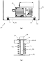
- the Fig. 1 shows a section of a pumping station 10 according to the invention in view.
- Fig. 1 a part of a housing 12 of the pumping station 10, in which a backing vacuum pump 14 in the form of a membrane vacuum pump is accommodated.
- a high vacuum pump supported by the pumping station 10 and in particular its housing 12 in the form, for example, of a turbomolecular vacuum pump, which is connected upstream of the backing vacuum pump 14 in the direction of flow.
- the backing pump 14 is located on a support element 16, which can be, for example, a support plate on which the backing pump 14 stands.
- the support element 16 can comprise two bending beams 18 which are spaced apart perpendicular to the plane of the drawing and run parallel to one another, on which the fore-vacuum pump 14 is fastened in such a way that it bridges the distance between the two bending beams 18.
- the respective bending beam 18 is elastically supported at its two ends by means of a spring element 20 on a base element 22 of the housing 12, which can prevent operational vibrations of the backing pump 14 from being transmitted to the housing 12 and from there to a mount mounted thereon Turbomolecular vacuum pump (not shown) can be transferred.
- the support element 16 or the bending beam 18 is supported on the base element 22 via a spring element 20 in the form of a helical compression spring 20, for which purpose the spring element 20 extends between the two mutually facing surfaces of the support element 16 and the base element 22.
- the support element 16 is by means of a fastening element 24 in the form of a bolt screw 24 clamped to the base element 22, the shaft 26 of the bolt screw 24 extending through the helical compression spring 20.
- the free end of the shaft 26 of the bolt screw 24 can be screwed either into an internal thread formed in the base element 22 or into a nut, which is located below the base element 22 in contact with the same.
- the screw head 28 rests on the top of the carrier element 16 via a washer 30, so that the same is secured against lifting forces on the base element 22.
- the washer 30 is not necessarily needed if the bore 34 of the support member 16 is so small that the screw head 28 does not fit through, or if a flange head screw is used.
- the fastening element 24 thus creates a transport lock, which can prevent the carrier element 16 from jumping off the spring element 20 during the transport of the pumping station 10.
- the shaft 26 of the fastening element 24 is surrounded by a spacer sleeve 32, which can preferably be made of a plastic material.
- the spacer sleeve 32 extends between the underside the washer 30 and the side of the base element 22 facing the carrier element 16.
- the spacer sleeve 32 extends through the opening 34 formed in the carrier element 16, through which the shaft 26 of the fastening element 24 also extends.
- the axial extension of the spacer sleeve 32 thus predetermines the maximum distance between the carrier element 16 and the base element 22, which can ensure that the fastening element 24 can only be tightened to the extent that the spring element 20 develops a preload force of a predetermined size.
- the clamping length which in technical mechanics refers to the thickness of the components to be connected, including any washers.
- the axial length of the spacer sleeve 32 should be chosen to be so large that in the unloaded state of the bearing arrangement, in which no pump is yet resting on the carrier element 16, the spring element 20 does not develop any preloading effect and thus the shaft 26 of the fastening element 24 is only affected by the tightening torque the fastening element 24 is under tension.
- the spring constant of the spring element 20, however, should be chosen so large that the spring element 20 does not block even during operation of a backing pump mounted on the carrier element 16.
- the spacer sleeve 32 is advisable to make from a plastic material, as this can ensure that it When there is contact between the spring element 20 and the spacer sleeve 32, there are no annoying rattling noises.
- a hollow cylindrical depression 36 is formed in the side of the carrier element 16 facing the base element 22, which receives the corresponding end of the spring element 20 and which is aligned coaxially with the opening 34 in the carrier element 16.
- the spring element 20 is thus held in the depression 36 in the radial direction, whereby the coaxial arrangement of the spring element 20, spacer sleeve 32 and fastening element 24 is permanently maintained.
- a dome 38 is formed in the form of a hollow cylindrical elevation, the helical compression spring 20 surrounding the dome 38, so that the helical compression spring 20 is held in place in the radial direction.
- the lower end of the spacer sleeve 32 which here also consists of a plastic material, rests on the dome 38, which means that the length of the shaft 26 of the fastening element 24, which experiences an expansion as a result of the tension of the support element 20 with the base element 22 , and the axial height extent of the dome 38 is smaller than in the embodiment of Fig. 2 .
- the dome 38 is provided with an internal thread (not shown) into which the free end of the shaft 26 is screwed;
- the dome 38 can also simply define a through opening through which the shaft 26 extends, below of the base element 22 or above the support element 16, a nut which rests on the base element 22 or on the support element 16 and into which the free end of the shaft 26 is screwed can be provided.
- a dome 38 is formed on the base element 22 and a depression 36 is formed in the support element 16 to secure the respective spring end.
- the support element 16 is a bending beam 18 with an angular cross-section, the vertical angle leg 40 in a corresponding manner as the horizontal angle leg for a bearing arrangement consisting of spring element 20, spacer sleeve 32 and fastening element 24 on a vertical base element section 22 ' is secured.
Landscapes
- Engineering & Computer Science (AREA)
- General Engineering & Computer Science (AREA)
- Mechanical Engineering (AREA)
- Physics & Mathematics (AREA)
- Acoustics & Sound (AREA)
- Aviation & Aerospace Engineering (AREA)
- Non-Positive Displacement Air Blowers (AREA)
- Compressors, Vaccum Pumps And Other Relevant Systems (AREA)
- Applications Or Details Of Rotary Compressors (AREA)
Abstract
Description
- Die vorliegende Erfindung betrifft einen Pumpstand für eine Vakuumpumpe, insbesondere für eine Membranvakuumpumpe.
- Ein Vakuum-Pumpstand dient zur Aufnahme mehrerer Vakuumpumpen, welche strömungstechnisch miteinander verbunden und insbesondere hintereinandergeschaltet sind, um sich so hinsichtlich der erreichbaren Druckstufen zu ergänzen. Beispielsweise kann ein Vakuum-Pumpstand eine Membranvakuumpumpe als Vorvakuumpumpe sowie eine Turbomolekularpumpe als Hochvakuumpumpe umfassen. Wird die Membranvakuumpumpe dabei an dem Pumpstand bzw. an einem Basiselement desselben zur Aufnahme der Membranvakuumpumpe starr befestigt, können unter Umständen die während des Betriebs der Membranvakuumpumpe von derselben ausgehende Schwingungen in unerwünschter Weise auf die Turbomolekularvakuumpumpe übertragen werden, was zu Funktionsstörungen derselben führen kann.
- Ferner können während des Transports eines Pumpstands transportbedingte Impulse auf die beispielsweise als Membranvakuumpumpe oder als Drehschieberpumpe ausgebildete Vorvakuumpumpe übertragen werden, wenn diese starr an dem Pumpstand befestigt ist, was zu einer Beschädigung der Vorvakuumpumpe führen kann.
- Der Erfindung liegt daher die Aufgabe zugrunde, bei einem Vakuum-Pumpstand dafür zu sorgen, dass von einer Vakuumpumpe, insbesondere einer Vorvakuumpumpe, ausgehende Schwingungen nicht auf den Pumpstand übertragen werden, und dass gleichermaßen auch auf die Vakuumpumpe, insbesondere auf die Vorvakuumpumpe, des Pumpstands keine externen Impulse übertragen werden können. Ferner sollte dafür gesorgt werden, dass keine zusätzlichen Transportsicherungen für die Vakuumpumpe benötigt werden, die andernfalls bei der Inbetriebnahme des Pumpstands eigens gelöst werden müssen.
- Diese Aufgabe wird mit einem Pumpstand mit den Merkmalen des Anspruchs 1 und insbesondere dadurch gelöst, dass der Pumpstand über zumindest eine Lageranordnung verfügt, über die sich eine schwingungstechnische Entkopplung einer Vakuumpumpe von dem Pumpstand erzielen lässt.
- Die Lageranordnung verfügt dabei über ein Trägerelement zur Abstützung einer Vakuumpumpe, wobei es sich bei dem Trägerelement beispielsweise um eine ebene Platte oder ein oder mehrere Biegebalken zur Abstützung einer Vakuumpumpe handeln kann. Des Weiteren verfügt die Lageranordnung über zumindest ein Federelement in Form beispielsweise einer Schraubendruckfeder, über das bzw. die das Trägerelement an dem Basiselement des Pumpstands elastisch federnd abgestützt ist, wozu sich das Federelement zwischen einander zugewandten Seiten des Trägerelements und des Basiselements erstreckt. Handelt es sich bei dem Trägerelement beispielsweise um eine rechteckige Trägerplatte, so kann diese an ihren vier Ecken über dort befindliche Federelemente elastisch federnd an dem Basiselement des Pumpstands abgestützt sein.
- Um das Trägerelement an dem Basiselement verliersicher halten und gegen abhebende Kräfte während des Transports des Pumpstands sichern zu können, verfügt die Lageranordnung des Weiteren über zumindest ein Befestigungselement beispielsweise in Form einer Schraube mit einem Schaft, das sich durch das Federelement hindurch erstreckt und mittels dessen das Trägerelement mit dem Basiselement verspannt ist, wobei es insbesondere vorgesehen sein kann, dass das Trägerelement mittels des Befestigungselements entgegen der Vorspannwirkung des Federelements mit dem Basiselement verspannt ist.
- Da das zumindest eine Federelement im unbelasteten Zustand der Lageranordnung keine Vorspannwirkung auf das Trägerelement aufbringen bzw. kräftefrei sein sollte und damit ferner alle Befestigungselemente, über die das Trägerelement mit dem Basiselement des Pumpstands abgestützt ist, gleich stark angezogen werden können, umfasst die Lageranordnung darüber hinaus eine Distanzhülse, die von dem Federelement umgeben ist und die ihrerseits den Schaft des Befestigungselements über eine Längenerstreckung hinweg umgibt, die infolge der Verspannung des Trägerelements mit dem Basiselement eine Dehnung erfährt.
- Der Schaft des Befestigungselements, die Distanzhülse und das Federelement sind somit also im Wesentlichen konzentrisch zueinander angeordnet, wobei die Distanzhülse eine Längenerstreckung aufweist, die der Klemmlänge des Befestigungselements und somit der Länge des Schafts entspricht, die infolge der Verspannung des Trägerelements mit dem Basiselement gedehnt wird. Anders ausgedrückt entspricht die Länge der Distanzhülse jenem Abschnitt des Schafts, der infolge der Verspannung des Trägerelements mit dem Basiselement gedehnt wird. Hierzu ist die axiale Länge der Distanzhülse so groß zu wählen, dass der Schaft des Befestigungselements bereits im unbelasteten Zustand der Lageranordnung unter Zug steht. Gleichermaßen sollte die axiale Länge der Distanzhülse derart auf die axiale Erstreckung des Federelements abgestimmt sein, dass dieses im unbelasteten Zustand der Lageranordnung d.h. ohne einer auf dem Trägerelement befindlichen Vakuumpumpe kräftefrei ist bzw. keine Vorspannwirkung entfaltet.
- Durch die Distanzhülse wird somit der gegenseitige Abstand zwischen dem Trägerelement und dem Basiselement im unbelasteten Zustand der Lageranordnung vorgegeben, womit gleichermaßen sichergestellt wird, dass das Federelement im unbelasteten Zustand der Lageranordnung keine Vorspannwirkung entfaltet. Anders ausgedrückt kann also das Befestigungselement nur so weit angezogen werden, bis sich ein vorgegebener Abstand zwischen dem Trägerelement und dem Basiselement einstellt.
- Im Folgenden wird nun auf bevorzugte Ausführungsformen der Erfindung eingegangen. Weitere Ausführungsformen können sich auch aus den abhängigen Ansprüchen, der Figurenbeschreibung sowie den Zeichnungen selbst ergeben.
- So kann es gemäß einer Ausführungsform vorgesehen sein, dass an dem Trägerelement und/oder an dem Basiselement zumindest eine Führung für das Federelement ausgebildet ist, durch die sichergestellt werden kann, dass das Federelement während des Betriebs der Pumpe rein axial komprimiert wird. Durch die Führung können somit etwaige Querauslenkungen des Federelements verhindert werden. Gleichermaßen dient eine derartige Führung als Lagesicherung für das Federelement, damit dieses seine konzentrische Lage bezüglich des Befestigungselements und der den Schaft des Befestigungselements umgebenden Distanzhülse beibehält. Hierdurch kann verhindert werden, dass das Federelement mit der Distanzhülse in Kontakt gelangt, was ansonsten während des Betriebs einer Vakuumpumpe zu unerwünschten Klappergeräuschen führen kann.
- Gemäß einer Ausführungsform kann es sich bei der in Rede stehenden Führung beispielsweise um einen an dem Basiselement und/oder an dem Trägerelement ausgebildeten Dom handeln, den das Federelement umgibt und mit dem ein jeweiliges Ende der Distanzhülse in Kontakt steht. Insbesondere kann es dabei vorgesehen sein, dass ein Ende des Schafts des Befestigungselements in den Dom eingeschraubt ist, wozu in diesem ein Hohlraum mit einem entsprechenden Innengewinde ausgebildet sein kann.
- Dadurch, dass das Federelement den Dom umgibt, wird dessen radiale Ausrichtung gegenüber der auf dem Dom aufstehenden Distanzhülse fixiert, so dass das Federelement die Distanzhülse in der gewünschten Weise nicht berührt, was andernfalls unerwünschte Klappergeräusche verursachen kann.
- Zusätzlich oder alternativ zu der zuvor beschriebenen Ausführungsform kann es sich bei der Führung auch um eine in dem Basiselement und/oder in dem Trägerelement ausgebildete Senkung in Form einer Sacklochbohrung handeln, die das jeweilige Ende des Federelements aufnimmt. Auch hierdurch kann eine etwaige Fehlausrichtung des Federelements gegenüber der Distanzhülse verhindert werden, um so unerwünschte Klappergeräusche zu verhindern, die andernfalls entstehen könnten, wenn das Federelement mit der Distanzhülse in Anlage gelangt.
- Gemäß noch einer weiteren Ausführungsform kann es vorgesehen sein, dass zur Führung der Distanzhülse an dem Basiselement ein Dom ausgebildet ist, den das Federelement umgibt und auf dem ein Ende der Distanzhülse aufsteht, wohingegen in dem Trägerelement eine entsprechende Senkung ausgebildet ist, die das andere Ende des Federelements aufnimmt. Alternativ hierzu kann jedoch auch der Dom an dem Trägerelement und die Senkung in dem Basiselement ausgebildet sein.
- Gemäß einer weiteren Ausführungsform kann es vorgesehen sein, dass die Distanzhülse aus einem Kunststoffmaterial gefertigt ist, da hierdurch selbst dann, wenn es bei nicht streng axial verlaufenden Schwingungen zum Kontakt zwischen Federelement und Distanzstück kommen sollte, sichergestellt werden kann, dass hierdurch keine unerwünschten Klappergeräusche hervorgerufen werden. Gleichermaßen können durch die Ausbildung der Distanzhülse aus einem Kunststoffmaterial unerwünschte Klappergeräusche infolge eines Kontakts zwischen der Distanzhülse und dem Schaft des Befestigungselements sowie dem Trägerelement verhindert werden. Die Ausgestaltung der Distanzhülse aus einem Kunststoffmaterial kann sich insbesondere dann als vorteilhaft erweisen, wenn keine Führungen für das Federelement vorgesehen sind, da in diesem Falle selbst dann unerwünschte Klappergeräusche verhindert werden können, wenn es zu einem Kontakt zwischen dem Federelement und der Distanzhülse kommen sollte.
- Wie bereits zuvor kurz erläutert wurde, kann es sich bei dem Trägerelement beispielsweise um eine Trägerplatte handeln, auf der eine Vakuumpumpe befestigt werden kann. Alternativ hierzu kann es gemäß einer weiteren Ausführungsform vorgesehen sein, dass das Trägerelement zumindest einen Biegebalken umfasst, der an seinen Enden jeweils über ein Federelement an dem Basiselement abgestützt und mittels eines Befestigungselements, dessen Schaft sich durch eine Distanzhülse erstreckt, mit dem Basiselement verspannt ist. Der Biegebalken ist somit an seinen beiden Enden mit einer Lageranordnung, wie sie zuvor beschrieben wurde, gelagert, so dass der Biegebalken im statischen Sinne einen Einfeldträger bildet. Vorzugsweise umfasst das Trägerelement zwei derartige Biegebalken, welche im Wesentlichen parallel zueinander verlaufen. In diesem Falle kann auf den beiden Biegebalken eine Vakuumpumpe befestigt sein, die den Abstand zwischen den beiden Biegebalken überbrückt. Die beiden Biegebalken sind somit weitestgehend schwingungstechnisch voneinander entkoppelt, so dass eine Auslenkung des einen Biegebalkens keinen Einfluss auf die Auslenkung des anderen Biegebalkens hat und umgekehrt.
- Damit selbst sehr große Auslenkungen des Federelements nicht auf den Pumpstand übertragen werden, kann es gemäß einer bevorzugten Ausführungsform vorgesehen sein, dass das jeweilige Federelement einer jeden Lageranordnung eine Federkonstante aufweist, die so groß gewählt ist, dass das Federelement selbst während des Betriebs der Vakuumpumpe nicht auf Block geht.
- Um nicht nur für eine schwingungstechnische Entkopplung zwischen Vakuumpumpe und Pumpstand in vertikaler Richtung, sondern auch in horizontaler Richtung zu sorgen, kann es gemäß einer weiteren Ausführungsform ferner vorgesehen sein, dass der Pumpstand zumindest zwei Lageranordnungen umfasst, deren Federelemente, Distanzhülsen und Befestigungselemente senkrecht zueinander orientiert sind.
- Im Folgenden wird die Erfindung nun rein exemplarisch und unter Bezugnahme auf die Zeichnungen beschrieben, in denen:
- Fig. 1
- einen Abschnitt eines erfindungsgemäßen Pumpstands in einer Ansicht zeigt;
- Fig. 2
- eine erste Ausführungsform einer erfindungsgemäßen Lageranordnung zeigt;
- Fig. 3
- eine zweite Ausführungsform einer erfindungsgemäßen Lageranordnung zeigt;
- Fig. 4
- eine dritte Ausführungsform einer erfindungsgemäßen Lageranordnung zeigt;
- Fig. 5
- eine vierte Ausführungsform einer erfindungsgemäßen Lageranordnung zeigt; und
- Fig. 6
- eine Ausführungsform mit zwei senkrecht zueinander orientierten Lageranordnungen zeigt.
- Die
Fig. 1 zeigt einen Abschnitt eines erfindungsgemäßen Pumpstands 10 in der Ansicht. Insbesondere zeigt dieFig. 1 einen Teil eines Gehäuses 12 des Pumpstands 10, in dem eine Vorvakuumpumpe 14 in Form einer Membranvakuumpumpe untergebracht ist. Nicht dargestellt ist eine durch den Pumpstand 10 und insbesondere dessen Gehäuse 12 gestützte Hochvakuumpumpe in Form beispielsweise einer Turbomolekularvakuumpumpe, die der Vorvakuumpumpe 14 in Strömungsrichtung vorgeschaltet ist. - Wie der
Fig. 1 entnommen werden kann, befindet sich die Vorvakuumpumpe 14 auf einem Trägerelement 16, bei dem es sich beispielsweise um eine Trägerplatte handeln kann, auf der die Vorvakuumpumpe 14 aufsteht. Alternativ hierzu kann das Trägerelement 16 zwei senkrecht zur Zeichenebene beabstandete und parallel zueinander verlaufende Biegebalken 18 umfassen, auf denen die Vorvakuumpumpe 14 derart befestigt ist, dass sie den Abstand zwischen den beiden Biegebalken 18 überbrückt. - Wie bereits der
Fig. 1 entnommen werden kann, ist der jeweilige Biegebalken 18 an seinen beiden Enden mittels jeweils eines Federelements 20 an einem Basiselement 22 des Gehäuses 12 elastisch abgestützt, wodurch verhindert werden kann, dass betriebsbedingte Schwingungen der Vorvakuumpumpe 14 auf das Gehäuse 12 und von dort auf eine daran gelagerte Turbomolekularvakuumpumpe (nicht dargestellt) übertragen werden können. - Wie der vergrößerten Darstellung der
Fig. 2 entnommen werden, ist das Trägerelement 16 bzw. der Biegebalken 18 an dem Basiselement 22 über ein Federelement 20 in Form einer Schraubendruckfeder 20 abgestützt, wozu sich das Federelement 20 zwischen den beiden einander zugewandten Flächen des Trägerelements 16 und des Basiselements 22 erstrecken. Um das Trägerelement 16 bzw. den Biegebalken 18 während des Transports des Pumpenstands 10 gegen abhebende Kräfte sichern zu können, ist das Trägerelement 16 mittels eines Befestigungselements 24 in Form einer Bolzenschraube 24 mit dem Basiselement 22 verspannt, wobei sich der Schaft 26 der Bolzenschraube 24 durch die Schraubendruckfeder 20 hindurcherstreckt. Zur Verspannung des Trägerelements 16 mit dem Basiselement 22 kann das freie Ende des Schafts 26 der Bolzenschraube 24 entweder in ein in dem Basiselement 22 ausgebildetes Innengewinde oder in eine Mutter eingeschraubt werden, welche sich unterhalb des Basiselements 22 in Anlage mit demselben befindet. Der Schraubenkopf 28 liegt bei der dargestellten Ausführungsform hingegen über eine Unterlegscheibe 30 auf der Oberseite des Trägerelements 16 an, so dass dasselbe gegen abhebende Kräfte an dem Basiselement 22 gesichert ist. Die Unterlegscheibe 30 wird jedoch nicht zwangsweise benötigt, wenn die Bohrung 34 des Trägerelements 16 so klein ist, dass der Schraubenkopf 28 nicht hindurchpasst, oder wenn eine Flanschkopfschraube verwendet wird. Durch das Befestigungselement 24 wird somit eine Transportsicherung geschaffen, durch die verhindert werden kann, dass das Trägerelement 16 während des Transports des Pumpstands 10 von dem Federelement 20 herunterspringen kann. Es wird somit keine separate Transportsicherung benötigt, mit der das Trägerelement 16 für den Transport mit dem Basiselement 22 soweit verspannt werden kann, bis das Federelement 20 auf Block geht. Bei einer derartigen separaten Transportsicherung kann es vorkommen, dass nach dem Transport vergessen wird, die Transportsicherung zu lösen, was während des Betriebs zu einer unerwünschten Schwingungsübertragung auf die Hochvakuumpumpe führen kann. Da das Befestigungselement 24 der erfindungsgemäßen Lageranordnung nach dem Transport des Pumpstands 10 nicht entfernt werden braucht, wird somit eine Transportsicherung geschaffen, die für Anwendungsfehler unanfällig ist. - Da die von dem Federelement 20 ausgehende Vorspannung umso größer ist, je näher das Trägerelement 16 mittels des Befestigungselements 24 an das Basiselement 22 gezogen wird, ist der Schaft 26 des Befestigungselements 24 von einer Distanzhülse 32 umgeben, die vorzugsweise aus einem Kunststoffmaterial gefertigt sein kann. Konkret erstreckt sich dabei die Distanzhülse 32 zwischen der Unterseite der Unterlegscheibe 30 und der dem Trägerelement 16 zugewandten Seite des Basiselements 22. Insbesondere erstreckt sich die Distanzhülse 32 durch die in dem Trägerelement 16 ausgebildete Öffnung 34, durch die sich auch der Schaft 26 des Befestigungselements 24 erstreckt. Durch die axiale Erstreckung der Distanzhülse 32 wird somit der maximale Abstand zwischen dem Trägerelement 16 und dem Basiselement 22 vorgegeben, wodurch sichergestellt werden kann, dass das Befestigungselement 24 nur genau so weit angezogen werden kann, dass das Federelement 20 eine Vorspannkraft vorbestimmter Größe entfaltet.
- Da sich die Distanzhülse 32 zwischen der Unterseite der Unterlegscheibe 30 und der dem Trägerelement 16 zugewandten Seite des Basiselements 22 erstreckt, ist durch die axiale Längenerstreckung der Distanzhülse 32 somit die unter Spannung gedehnte Länge des Schraubenschafts 26 vorgegeben. Diese unter Spannung gedehnte Länge eines Schraubenschafts wird üblicherweise als Klemmlänge bezeichnet, worunter in der technischen Mechanik die Dicke der zu verbindenden Bauteile einschließlich gegebenenfalls vorhandener Unterlegscheiben bezeichnet wird.
- Die axiale Länge der Distanzhülse 32 sollte dabei so groß gewählt sein, dass im unbelasteten Zustand der Lageranordnung, in dem also noch keine Pumpe auf dem Trägerelement 16 ruht, das Federelement 20 keine Vorspannwirkung entfaltet und somit der Schaft 26 des Befestigungselements 24 ausschließlich durch das Anzugsmoment des Befestigungselements 24 unter Zug steht. Die Federkonstante des Federelements 20 sollte hingegen so groß gewählt sein, dass das Federelement 20 selbst während des Betriebs einer auf dem Trägerelement 16 montierten Vorvakuumpumpe nicht auf Block geht.
- Wie bereits zuvor erwähnt, bietet es sich an, die Distanzhülse 32 aus einem Kunststoffmaterial zu fertigen, da hierdurch sichergestellt werden kann, dass es bei einem Kontakt zwischen dem Federelement 20 und der Distanzhülse 32 zu keinen störenden Klappergeräuschen kommt.
- Um jedoch einen derartigen Kontakt zwischen Federelement 20 und Distanzhülse 32 von vornherein ausschließen zu können, ist es bei der in der
Fig. 3 dargestellten Ausführungsform vorgesehen, dass in der dem Basiselement 22 zugewandten Seite des Trägerelements 16 eine hohlzylindrische Senkung 36 ausgebildet ist, die das entsprechende Ende des Federelements 20 aufnimmt und die koaxial mit der Öffnung 34 in dem Trägerelement 16 ausgerichtet ist. Das Federelement 20 wird somit in der Senkung 36 in radialer Richtung gehalten, wodurch die koaxiale Anordnung von Federelement 20, Distanzhülse 32 und Befestigungselement 24 dauerhaft erhalten bleibt. - Alternativ zu der in der
Fig. 3 dargestellten Ausführungsform ist es bei der in derFig. 4 dargestellten Ausführungsform vorgesehen, dass an der dem Trägerelement 16 zugewandten Seite des Basiselements 22 ein Dom 38 in Form einer hohlzylindrischen Erhebung ausgebildet ist, wobei die Schraubendruckfeder 20 den Dom 38 umgibt, so dass die Schraubendruckfeder 20 in radialer Richtung an Ort und Stelle gehalten wird. Darüber hinaus steht bei der in derFig. 4 dargestellten Ausführungsform das untere Ende der Distanzhülse 32, die auch hier aus einem Kunststoffmaterial besteht, auf dem Dom 38 auf, was bedeutet, dass die Länge des Schafts 26 des Befestigungselements 24, die infolge der Verspannung des Trägerelements 20 mit dem Basiselement 22 eine Dehnung erfährt, und die axiale Höhenerstreckung des Doms 38 geringer ist als bei der Ausführungsform derFig. 2 . - Zwar ist bei der Ausführungsform der
Fig. 4 der Dom 38 mit einem Innengewinde (nicht dargestellt) versehen, in das das freie Ende des Schafts 26 eingeschraubt ist; alternativ hierzu kann jedoch der Dom 38 auch lediglich eine Durchgangsöffnung definieren, durch die sich der Schaft 26 hindurcherstreckt, wobei unterhalb des Basiselements 22 oder oberhalb des Trägerelements 16 eine an dem Basiselement 22 bzw. an dem Trägerelement 16 anliegende Mutter vorgesehen sein kann, in die das freie Ende des Schafts 26 eingeschraubt ist. - Bei der Ausführungsform der
Fig. 5 handelt es sich gewissermaßen um eine Kombination der Ausführungsformen derFig. 3 und 4 , da gemäß der Ausführungsform derFig. 5 an dem Basiselement 22 ein Dom 38 und in dem Trägerelement 16 eine Senkung 36 zur Sicherung des jeweiligen Federendes ausgebildet ist. - Mittels der zuvor beschriebenen Lageranordnungen kann somit für eine schwingungstechnische Entkopplung zwischen einer Vakuumpumpe 14 und einem Pumpenstand 10 in vertikaler Richtung gesorgt werden. Um jedoch auch horizontale Pumpenschwingungen unterdrücken oder zumindest dämpfen zu können, kann es gemäß der in der
Fig. 6 dargestellten Ausführungsform vorgesehen sein, dass es sich bei dem Trägerelement 16 um einen Biegebalken 18 mit winkelförmigem Querschnitt handelt, wobei der vertikale Winkelschenkel 40 in entsprechender Weise wie der horizontale Winkelschenkel für eine Lageranordnung aus Federelement 20, Distanzhülse 32 und Befestigungselement 24 an einem vertikalen Basiselementabschnitt 22' gesichert ist. -
- 10
- Pumpstand
- 12
- Gehäuse
- 14
- Vorvakuumpumpe
- 16
- Trägerelement
- 18
- Biegebalken
- 20
- Federelement
- 22
- Basiselement
- 22'
- Basiselementabschnitt
- 24
- Befestigungselement/Bolzenschraube
- 26
- Schaft
- 28
- Schraubenkopf
- 30
- Unterlegscheibe
- 32
- Distanzhülse
- 34
- Öffnung
- 36
- Senkung
- 38
- Dom
- 40
- vertikaler Winkelschenkel
- 42
- horizontaler Winkelschenkel
Claims (13)
- Pumpstand (10) für eine Vakuumpumpe (14), insbesondere für eine Vorvakuumpumpe, wobei der Pumpstand (10) ein Basiselement (22) umfasst, an dem eine Lageranordnung zur schwingungstechnischen Entkopplung einer Vakuumpumpe (14), insbesondere einer Vorvakuumpumpe, von dem Pumpstand (10) vorgesehen ist, wobei die Lageranordnung umfasst:- ein Trägerelement (16) zur zumindest mittelbaren Abstützung einer Vakuumpumpe (14);- zumindest ein Federelement (20), über das das Trägerelement (16) an dem Basiselement (22) abgestützt ist, wozu sich das Federelement (20) zwischen einander zugewandten Seiten des Trägerelements (16) und des Basiselements (22) erstreckt;- ein Befestigungselement (24) mit einem Schaft (26), insbesondere in Form einer Schraube, mittels dessen das Trägerelement (16) mit dem Basiselement (22) verspannt ist; und- eine Distanzhülse (32), die von dem Federelement (20) umgeben ist und die ihrerseits den Schaft (26) des Befestigungselements (24) über eine Längenerstreckung umgibt, die infolge der Verspannung des Trägerelements (16) mit dem Basiselement (22) eine Dehnung erfährt.
- Pumpstand (10) nach Anspruch 1,
wobei die axiale Länge der Distanzhülse (32) so gewählt ist, dass in einem unbelasteten Zustand der Lageranordnung der Schaft (26) des Befestigungselements (24) ausschließlich infolge des Anzugsmoments des Befestigungselements (24) unter Zug steht. - Pumpstand (10) nach Anspruch 1 oder 2,
wobei das Federelement (20) im unbelasteten Zustand der Lageranordnung nur durch das Trägerelement (16) belastet ist. - Pumpstand (10) nach einem der vorstehenden Ansprüche,
wobei das Federelement (20) eine Schraubendruckfeder (20) ist. - Pumpstand (10) nach einem der vorstehenden Ansprüche,
wobei an dem Trägerelement (16) und/oder an dem Basiselement (22) zumindest eine Führung für das Federelement (20) ausgebildet ist. - Pumpstand (10) nach Anspruch 5,wobei es sich bei der Führung um einen an dem Basiselement (22)und/oder an dem Trägerelement (16) ausgebildeten Dom (38) handelt, den das Federelement (20) umgibt und auf dem ein Ende der Distanzhülse (32) aufsteht,wobei es insbesondere vorgesehen ist, dass der Schaft (26) des Befestigungselements (24) in den Dom (38) eingeschraubt ist.
- Pumpstand (10) nach Anspruch 5,
wobei es sich bei der Führung um eine in dem Basiselement (22) und/oder in dem Trägerelement (16) ausgebildete Senkung (36) handelt, die das jeweilige Ende des Federelements (20) aufnimmt. - Pumpstand (10) nach einem der vorstehenden Ansprüche,
wobei die Distanzhülse (32) aus einem Kunststoffmaterial gefertigt ist. - Pumpstand (10) nach einem der vorstehenden Ansprüche,
wobei das Trägerelement (16) zumindest einen Biegebalken (18) umfasst, der an seinen Enden jeweils über ein Federelement (20) an dem Basiselement (22) abgestützt und mittels eines Befestigungselements (24), dessen Schaft (26) sich durch eine Distanzhülse (32) erstreckt, mit dem Basiselement (22) verspannt ist. - Pumpstand (10) nach Anspruch 9,
wobei das Trägerelement (16) zwei parallel zueinander verlaufende Biegebalken (18) umfasst. - Pumpstand (10) nach Anspruch 10,
wobei auf den beiden Biegebalken (18) eine den Abstand zwischen den beiden Biegebalken (18) überbrückende Vakuumpumpe (14) befestigt ist, insbesondere eine Membranvakuumpumpe (14) oder eine Drehschieberpumpe. - Pumpstand (10) nach einem der vorstehenden Ansprüche,
wobei das Federelement (20) eine Federkonstante aufweist, die so gewählt ist, dass das Federelement (20) während des Betriebs der Vakuumpumpe (14) nicht auf Block geht. - Pumpstand (10) nach einem der vorstehenden Ansprüche,
wobei der Pumpstand (10) zumindest zwei Lageranordnungen umfasst, deren Federnelemente, Distanzhülsen (32) und Befestigungselemente (24) senkrecht zueinander orientiert sind.
Priority Applications (2)
| Application Number | Priority Date | Filing Date | Title |
|---|---|---|---|
| EP23178938.9A EP4265909B1 (de) | 2023-06-13 | 2023-06-13 | Pumpstand für eine vakuumpumpe |
| JP2023210075A JP2024178888A (ja) | 2023-06-13 | 2023-12-13 | 真空ポンプ用のポンプスタンド |
Applications Claiming Priority (1)
| Application Number | Priority Date | Filing Date | Title |
|---|---|---|---|
| EP23178938.9A EP4265909B1 (de) | 2023-06-13 | 2023-06-13 | Pumpstand für eine vakuumpumpe |
Publications (2)
| Publication Number | Publication Date |
|---|---|
| EP4265909A1 true EP4265909A1 (de) | 2023-10-25 |
| EP4265909B1 EP4265909B1 (de) | 2025-04-02 |
Family
ID=86764598
Family Applications (1)
| Application Number | Title | Priority Date | Filing Date |
|---|---|---|---|
| EP23178938.9A Active EP4265909B1 (de) | 2023-06-13 | 2023-06-13 | Pumpstand für eine vakuumpumpe |
Country Status (2)
| Country | Link |
|---|---|
| EP (1) | EP4265909B1 (de) |
| JP (1) | JP2024178888A (de) |
Families Citing this family (1)
| Publication number | Priority date | Publication date | Assignee | Title |
|---|---|---|---|---|
| KR102911607B1 (ko) * | 2025-07-16 | 2026-01-12 | 한석민 | 배터리 충격완화구조가 적용된 전자척 |
Citations (7)
| Publication number | Priority date | Publication date | Assignee | Title |
|---|---|---|---|---|
| US3428279A (en) * | 1965-03-03 | 1969-02-18 | Wright Barry Corp | Shock and vibration mount |
| US3785167A (en) * | 1972-12-11 | 1974-01-15 | Amana Refrigeration Inc | Noise reduction means for connecting refrigerant compressors in air conditioners |
| US4306708A (en) * | 1979-05-14 | 1981-12-22 | Tennessee Bolt And Screw Co., Inc. | Means for establishing a support post for a grommet |
| US20050169775A1 (en) * | 2004-01-30 | 2005-08-04 | Lg Electronics Inc. | Apparatus for supporting compressor |
| DE102014224050A1 (de) * | 2013-11-25 | 2015-05-28 | Continental Teves Ag & Co. Ohg | Hochgedämpftes Lagerelement |
| EP3298278B1 (de) * | 2015-05-22 | 2018-08-15 | Nidec Global Appliance Germany GmbH | Kältemittelverdichter |
| DE212020000257U1 (de) * | 2020-07-03 | 2020-12-01 | Suzhou Zhongchuang Sunshine New Energy Technology Co., Ltd. | Eine Stoßdämpfungsvorrichtung zur Wartung der Vakuumpumpe |
Family Cites Families (14)
| Publication number | Priority date | Publication date | Assignee | Title |
|---|---|---|---|---|
| US2687270A (en) * | 1950-11-21 | 1954-08-24 | Robinson Aviat Inc | Vibration absorption beam mount |
| JPS49138405U (de) * | 1973-03-22 | 1974-11-28 | ||
| JPS544637Y2 (de) * | 1973-05-24 | 1979-02-27 | ||
| JPS52103406U (de) * | 1976-02-04 | 1977-08-05 | ||
| JPS52166105U (de) * | 1976-06-10 | 1977-12-16 | ||
| JPS6024952Y2 (ja) * | 1976-08-06 | 1985-07-26 | 富士電機株式会社 | 空気調和機における電動圧縮機の支持装置 |
| JPS5745407Y2 (de) * | 1976-11-02 | 1982-10-06 | ||
| JPS5442002U (de) * | 1977-08-30 | 1979-03-20 | ||
| JPS5748393U (de) * | 1980-09-04 | 1982-03-18 | ||
| JPS6155181U (de) * | 1984-08-24 | 1986-04-14 | ||
| JPS61175585U (de) * | 1985-04-20 | 1986-11-01 | ||
| JPS6436578U (de) * | 1987-08-28 | 1989-03-06 | ||
| CN111895225B (zh) * | 2020-07-03 | 2022-03-29 | 宁波爱发科机械制造有限公司 | 可抽拉式真空机组机架 |
| CN213745947U (zh) * | 2020-11-30 | 2021-07-20 | 威固乐真空设备(浙江)有限公司 | 一种新型真空泵 |
-
2023
- 2023-06-13 EP EP23178938.9A patent/EP4265909B1/de active Active
- 2023-12-13 JP JP2023210075A patent/JP2024178888A/ja active Pending
Patent Citations (7)
| Publication number | Priority date | Publication date | Assignee | Title |
|---|---|---|---|---|
| US3428279A (en) * | 1965-03-03 | 1969-02-18 | Wright Barry Corp | Shock and vibration mount |
| US3785167A (en) * | 1972-12-11 | 1974-01-15 | Amana Refrigeration Inc | Noise reduction means for connecting refrigerant compressors in air conditioners |
| US4306708A (en) * | 1979-05-14 | 1981-12-22 | Tennessee Bolt And Screw Co., Inc. | Means for establishing a support post for a grommet |
| US20050169775A1 (en) * | 2004-01-30 | 2005-08-04 | Lg Electronics Inc. | Apparatus for supporting compressor |
| DE102014224050A1 (de) * | 2013-11-25 | 2015-05-28 | Continental Teves Ag & Co. Ohg | Hochgedämpftes Lagerelement |
| EP3298278B1 (de) * | 2015-05-22 | 2018-08-15 | Nidec Global Appliance Germany GmbH | Kältemittelverdichter |
| DE212020000257U1 (de) * | 2020-07-03 | 2020-12-01 | Suzhou Zhongchuang Sunshine New Energy Technology Co., Ltd. | Eine Stoßdämpfungsvorrichtung zur Wartung der Vakuumpumpe |
Also Published As
| Publication number | Publication date |
|---|---|
| EP4265909B1 (de) | 2025-04-02 |
| JP2024178888A (ja) | 2024-12-25 |
Similar Documents
| Publication | Publication Date | Title |
|---|---|---|
| DE69802721T2 (de) | Einsatz mit fester horizontaler Eigenfrequenz für schwingungsdämpfendes Lager | |
| EP2116740A2 (de) | Feder-Dämpfungssystem | |
| WO2013091671A1 (de) | Schwingungsgedämpftes möbel in der form eines tisches | |
| EP2217469A1 (de) | Verstellelement | |
| EP3063428A1 (de) | Lager | |
| EP4265909B1 (de) | Pumpstand für eine vakuumpumpe | |
| DE19917209A1 (de) | Vorrichtung zum Verspannen aufeinanderliegender Teile | |
| EP1884382A1 (de) | Schwingungsdämpfer mit einer Halterung | |
| DE3612064A1 (de) | Spannvorrichtung fuer treibriemen | |
| DE102018121219B4 (de) | Lagerbuchse für ein Sackloch und Lenkgetriebeaufhängung für ein Fahrzeug | |
| EP4377587A1 (de) | Lagerbuchse, lagerbuchsenanordnung und windenergieanlagenlager für windenergieanlagen | |
| EP2405146B1 (de) | Montagevorrichtung zur Befestigung einer Baugruppe an einem Bauteil, insbesondere einem Außengehäuse einer weiteren Baugruppe | |
| DE3508098C2 (de) | ||
| EP2784333B1 (de) | Vorrichtung zum Positionieren und Verspannen von zwei konzentrischen, einander teilweise überlappenden Bauteilen | |
| DE10006329C1 (de) | Gelenklager, insbesondere Stabilisatorlager für ein Fahrzeug | |
| EP2522879A2 (de) | Anordnung bestehend aus einem Lager und einem Zuganker | |
| DE29909115U1 (de) | Anordnung zur schwingungsisolierenden Halterung eines Elektromotors | |
| DE102008015552B4 (de) | Kompakt-Entkoppler-Modul | |
| EP4397447A1 (de) | Schwingungsfestes maschinengestell mit aluminiumprofilen | |
| WO2023179973A1 (de) | Schwingungsentkoppelungshülse sowie befestigungsvorrichtung mit einer schwingungsentkoppelungshülse | |
| DE20005583U1 (de) | Verbindungselement für eine elastische Verbindung zweier Bauteile | |
| DE10309792A1 (de) | Maschinenelement | |
| DE102015206419B4 (de) | Anordnung zur Befestigung eines Bauteils an einer Halterung | |
| AT527233B1 (de) | Keillager | |
| DE102013103691B4 (de) | Elastisches Lager |
Legal Events
| Date | Code | Title | Description |
|---|---|---|---|
| PUAI | Public reference made under article 153(3) epc to a published international application that has entered the european phase |
Free format text: ORIGINAL CODE: 0009012 |
|
| STAA | Information on the status of an ep patent application or granted ep patent |
Free format text: STATUS: THE APPLICATION HAS BEEN PUBLISHED |
|
| STAA | Information on the status of an ep patent application or granted ep patent |
Free format text: STATUS: REQUEST FOR EXAMINATION WAS MADE |
|
| AK | Designated contracting states |
Kind code of ref document: A1 Designated state(s): AL AT BE BG CH CY CZ DE DK EE ES FI FR GB GR HR HU IE IS IT LI LT LU LV MC ME MK MT NL NO PL PT RO RS SE SI SK SM TR |
|
| 17P | Request for examination filed |
Effective date: 20231019 |
|
| RBV | Designated contracting states (corrected) |
Designated state(s): AL AT BE BG CH CY CZ DE DK EE ES FI FR GB GR HR HU IE IS IT LI LT LU LV MC ME MK MT NL NO PL PT RO RS SE SI SK SM TR |
|
| STAA | Information on the status of an ep patent application or granted ep patent |
Free format text: STATUS: EXAMINATION IS IN PROGRESS |
|
| 17Q | First examination report despatched |
Effective date: 20231222 |
|
| R17C | First examination report despatched (corrected) |
Effective date: 20231221 |
|
| REG | Reference to a national code |
Ref country code: DE Ref legal event code: R079 Free format text: PREVIOUS MAIN CLASS: F04B0039000000 Ipc: F16F0001120000 Ref document number: 502023000762 Country of ref document: DE |
|
| GRAP | Despatch of communication of intention to grant a patent |
Free format text: ORIGINAL CODE: EPIDOSNIGR1 |
|
| STAA | Information on the status of an ep patent application or granted ep patent |
Free format text: STATUS: GRANT OF PATENT IS INTENDED |
|
| RIC1 | Information provided on ipc code assigned before grant |
Ipc: F04B 53/00 20060101ALI20241214BHEP Ipc: F04B 39/00 20060101ALI20241214BHEP Ipc: F16F 15/067 20060101ALI20241214BHEP Ipc: F16F 1/12 20060101AFI20241214BHEP |
|
| INTG | Intention to grant announced |
Effective date: 20250103 |
|
| GRAS | Grant fee paid |
Free format text: ORIGINAL CODE: EPIDOSNIGR3 |
|
| GRAA | (expected) grant |
Free format text: ORIGINAL CODE: 0009210 |
|
| STAA | Information on the status of an ep patent application or granted ep patent |
Free format text: STATUS: THE PATENT HAS BEEN GRANTED |
|
| AK | Designated contracting states |
Kind code of ref document: B1 Designated state(s): AL AT BE BG CH CY CZ DE DK EE ES FI FR GB GR HR HU IE IS IT LI LT LU LV MC ME MK MT NL NO PL PT RO RS SE SI SK SM TR |
|
| REG | Reference to a national code |
Ref country code: GB Ref legal event code: FG4D Free format text: NOT ENGLISH |
|
| REG | Reference to a national code |
Ref country code: CH Ref legal event code: EP |
|
| REG | Reference to a national code |
Ref country code: IE Ref legal event code: FG4D Free format text: LANGUAGE OF EP DOCUMENT: GERMAN |
|
| REG | Reference to a national code |
Ref country code: DE Ref legal event code: R096 Ref document number: 502023000762 Country of ref document: DE |
|
| REG | Reference to a national code |
Ref country code: NL Ref legal event code: MP Effective date: 20250402 |
|
| PG25 | Lapsed in a contracting state [announced via postgrant information from national office to epo] |
Ref country code: NL Free format text: LAPSE BECAUSE OF FAILURE TO SUBMIT A TRANSLATION OF THE DESCRIPTION OR TO PAY THE FEE WITHIN THE PRESCRIBED TIME-LIMIT Effective date: 20250402 |
|
| PG25 | Lapsed in a contracting state [announced via postgrant information from national office to epo] |
Ref country code: FI Free format text: LAPSE BECAUSE OF FAILURE TO SUBMIT A TRANSLATION OF THE DESCRIPTION OR TO PAY THE FEE WITHIN THE PRESCRIBED TIME-LIMIT Effective date: 20250402 Ref country code: ES Free format text: LAPSE BECAUSE OF FAILURE TO SUBMIT A TRANSLATION OF THE DESCRIPTION OR TO PAY THE FEE WITHIN THE PRESCRIBED TIME-LIMIT Effective date: 20250402 Ref country code: PT Free format text: LAPSE BECAUSE OF FAILURE TO SUBMIT A TRANSLATION OF THE DESCRIPTION OR TO PAY THE FEE WITHIN THE PRESCRIBED TIME-LIMIT Effective date: 20250804 |
|
| PGFP | Annual fee paid to national office [announced via postgrant information from national office to epo] |
Ref country code: DE Payment date: 20250827 Year of fee payment: 3 |
|
| REG | Reference to a national code |
Ref country code: LT Ref legal event code: MG9D |
|
| PG25 | Lapsed in a contracting state [announced via postgrant information from national office to epo] |
Ref country code: GR Free format text: LAPSE BECAUSE OF FAILURE TO SUBMIT A TRANSLATION OF THE DESCRIPTION OR TO PAY THE FEE WITHIN THE PRESCRIBED TIME-LIMIT Effective date: 20250703 Ref country code: NO Free format text: LAPSE BECAUSE OF FAILURE TO SUBMIT A TRANSLATION OF THE DESCRIPTION OR TO PAY THE FEE WITHIN THE PRESCRIBED TIME-LIMIT Effective date: 20250702 |
|
| PG25 | Lapsed in a contracting state [announced via postgrant information from national office to epo] |
Ref country code: PL Free format text: LAPSE BECAUSE OF FAILURE TO SUBMIT A TRANSLATION OF THE DESCRIPTION OR TO PAY THE FEE WITHIN THE PRESCRIBED TIME-LIMIT Effective date: 20250402 |
|
| PGFP | Annual fee paid to national office [announced via postgrant information from national office to epo] |
Ref country code: IT Payment date: 20250630 Year of fee payment: 3 |
|
| PG25 | Lapsed in a contracting state [announced via postgrant information from national office to epo] |
Ref country code: BG Free format text: LAPSE BECAUSE OF FAILURE TO SUBMIT A TRANSLATION OF THE DESCRIPTION OR TO PAY THE FEE WITHIN THE PRESCRIBED TIME-LIMIT Effective date: 20250402 |
|
| PG25 | Lapsed in a contracting state [announced via postgrant information from national office to epo] |
Ref country code: HR Free format text: LAPSE BECAUSE OF FAILURE TO SUBMIT A TRANSLATION OF THE DESCRIPTION OR TO PAY THE FEE WITHIN THE PRESCRIBED TIME-LIMIT Effective date: 20250402 |
|
| PG25 | Lapsed in a contracting state [announced via postgrant information from national office to epo] |
Ref country code: RS Free format text: LAPSE BECAUSE OF FAILURE TO SUBMIT A TRANSLATION OF THE DESCRIPTION OR TO PAY THE FEE WITHIN THE PRESCRIBED TIME-LIMIT Effective date: 20250702 |
|
| PG25 | Lapsed in a contracting state [announced via postgrant information from national office to epo] |
Ref country code: IS Free format text: LAPSE BECAUSE OF FAILURE TO SUBMIT A TRANSLATION OF THE DESCRIPTION OR TO PAY THE FEE WITHIN THE PRESCRIBED TIME-LIMIT Effective date: 20250802 |
|
| PG25 | Lapsed in a contracting state [announced via postgrant information from national office to epo] |
Ref country code: LV Free format text: LAPSE BECAUSE OF FAILURE TO SUBMIT A TRANSLATION OF THE DESCRIPTION OR TO PAY THE FEE WITHIN THE PRESCRIBED TIME-LIMIT Effective date: 20250402 |
|
| REG | Reference to a national code |
Ref country code: DE Ref legal event code: R097 Ref document number: 502023000762 Country of ref document: DE |
|
| PG25 | Lapsed in a contracting state [announced via postgrant information from national office to epo] |
Ref country code: DK Free format text: LAPSE BECAUSE OF FAILURE TO SUBMIT A TRANSLATION OF THE DESCRIPTION OR TO PAY THE FEE WITHIN THE PRESCRIBED TIME-LIMIT Effective date: 20250402 Ref country code: SM Free format text: LAPSE BECAUSE OF FAILURE TO SUBMIT A TRANSLATION OF THE DESCRIPTION OR TO PAY THE FEE WITHIN THE PRESCRIBED TIME-LIMIT Effective date: 20250402 |
|
| PG25 | Lapsed in a contracting state [announced via postgrant information from national office to epo] |
Ref country code: EE Free format text: LAPSE BECAUSE OF FAILURE TO SUBMIT A TRANSLATION OF THE DESCRIPTION OR TO PAY THE FEE WITHIN THE PRESCRIBED TIME-LIMIT Effective date: 20250402 |
|
| PG25 | Lapsed in a contracting state [announced via postgrant information from national office to epo] |
Ref country code: SK Free format text: LAPSE BECAUSE OF FAILURE TO SUBMIT A TRANSLATION OF THE DESCRIPTION OR TO PAY THE FEE WITHIN THE PRESCRIBED TIME-LIMIT Effective date: 20250402 |
|
| PG25 | Lapsed in a contracting state [announced via postgrant information from national office to epo] |
Ref country code: MC Free format text: LAPSE BECAUSE OF FAILURE TO SUBMIT A TRANSLATION OF THE DESCRIPTION OR TO PAY THE FEE WITHIN THE PRESCRIBED TIME-LIMIT Effective date: 20250402 |
|
| PLBE | No opposition filed within time limit |
Free format text: ORIGINAL CODE: 0009261 |
|
| STAA | Information on the status of an ep patent application or granted ep patent |
Free format text: STATUS: NO OPPOSITION FILED WITHIN TIME LIMIT |
|
| REG | Reference to a national code |
Ref country code: CH Ref legal event code: L10 Free format text: ST27 STATUS EVENT CODE: U-0-0-L10-L00 (AS PROVIDED BY THE NATIONAL OFFICE) Effective date: 20260211 |
|
| PG25 | Lapsed in a contracting state [announced via postgrant information from national office to epo] |
Ref country code: LU Free format text: LAPSE BECAUSE OF NON-PAYMENT OF DUE FEES Effective date: 20250613 |
|
| REG | Reference to a national code |
Ref country code: BE Ref legal event code: MM Effective date: 20250630 |
|
| PG25 | Lapsed in a contracting state [announced via postgrant information from national office to epo] |
Ref country code: RO Free format text: LAPSE BECAUSE OF FAILURE TO SUBMIT A TRANSLATION OF THE DESCRIPTION OR TO PAY THE FEE WITHIN THE PRESCRIBED TIME-LIMIT Effective date: 20250402 |
|
| 26N | No opposition filed |
Effective date: 20260105 |
|
| PG25 | Lapsed in a contracting state [announced via postgrant information from national office to epo] |
Ref country code: IE Free format text: LAPSE BECAUSE OF NON-PAYMENT OF DUE FEES Effective date: 20250613 |
|
| PG25 | Lapsed in a contracting state [announced via postgrant information from national office to epo] |
Ref country code: BE Free format text: LAPSE BECAUSE OF NON-PAYMENT OF DUE FEES Effective date: 20250630 |
|
| PG25 | Lapsed in a contracting state [announced via postgrant information from national office to epo] |
Ref country code: FR Free format text: LAPSE BECAUSE OF NON-PAYMENT OF DUE FEES Effective date: 20250630 |
|
| PG25 | Lapsed in a contracting state [announced via postgrant information from national office to epo] |
Ref country code: LT Free format text: LAPSE BECAUSE OF FAILURE TO SUBMIT A TRANSLATION OF THE DESCRIPTION OR TO PAY THE FEE WITHIN THE PRESCRIBED TIME-LIMIT Effective date: 20250402 |
|
| PGFP | Annual fee paid to national office [announced via postgrant information from national office to epo] |
Ref country code: AT Payment date: 20260714 Year of fee payment: 4 |
|
| PGFP | Annual fee paid to national office [announced via postgrant information from national office to epo] |
Ref country code: CZ Payment date: 20260609 Year of fee payment: 4 |
|
| PG25 | Lapsed in a contracting state [announced via postgrant information from national office to epo] |
Ref country code: CY Free format text: LAPSE BECAUSE OF FAILURE TO SUBMIT A TRANSLATION OF THE DESCRIPTION OR TO PAY THE FEE WITHIN THE PRESCRIBED TIME-LIMIT Effective date: 20250402 Ref country code: SE Free format text: LAPSE BECAUSE OF FAILURE TO SUBMIT A TRANSLATION OF THE DESCRIPTION OR TO PAY THE FEE WITHIN THE PRESCRIBED TIME-LIMIT Effective date: 20250402 |