EP4265762A1 - Steel sheet for seismic damper having superior toughness property and manufacturing method of same - Google Patents
Steel sheet for seismic damper having superior toughness property and manufacturing method of same Download PDFInfo
- Publication number
- EP4265762A1 EP4265762A1 EP21906923.4A EP21906923A EP4265762A1 EP 4265762 A1 EP4265762 A1 EP 4265762A1 EP 21906923 A EP21906923 A EP 21906923A EP 4265762 A1 EP4265762 A1 EP 4265762A1
- Authority
- EP
- European Patent Office
- Prior art keywords
- steel sheet
- content
- seismic damper
- scale layer
- less
- Prior art date
- Legal status (The legal status is an assumption and is not a legal conclusion. Google has not performed a legal analysis and makes no representation as to the accuracy of the status listed.)
- Pending
Links
Images

Classifications
-
- C—CHEMISTRY; METALLURGY
- C22—METALLURGY; FERROUS OR NON-FERROUS ALLOYS; TREATMENT OF ALLOYS OR NON-FERROUS METALS
- C22C—ALLOYS
- C22C38/00—Ferrous alloys, e.g. steel alloys
- C22C38/001—Ferrous alloys, e.g. steel alloys containing N
-
- C—CHEMISTRY; METALLURGY
- C21—METALLURGY OF IRON
- C21D—MODIFYING THE PHYSICAL STRUCTURE OF FERROUS METALS; GENERAL DEVICES FOR HEAT TREATMENT OF FERROUS OR NON-FERROUS METALS OR ALLOYS; MAKING METAL MALLEABLE, e.g. BY DECARBURISATION OR TEMPERING
- C21D6/00—Heat treatment of ferrous alloys
- C21D6/005—Heat treatment of ferrous alloys containing Mn
-
- C—CHEMISTRY; METALLURGY
- C21—METALLURGY OF IRON
- C21D—MODIFYING THE PHYSICAL STRUCTURE OF FERROUS METALS; GENERAL DEVICES FOR HEAT TREATMENT OF FERROUS OR NON-FERROUS METALS OR ALLOYS; MAKING METAL MALLEABLE, e.g. BY DECARBURISATION OR TEMPERING
- C21D6/00—Heat treatment of ferrous alloys
- C21D6/008—Heat treatment of ferrous alloys containing Si
-
- C—CHEMISTRY; METALLURGY
- C21—METALLURGY OF IRON
- C21D—MODIFYING THE PHYSICAL STRUCTURE OF FERROUS METALS; GENERAL DEVICES FOR HEAT TREATMENT OF FERROUS OR NON-FERROUS METALS OR ALLOYS; MAKING METAL MALLEABLE, e.g. BY DECARBURISATION OR TEMPERING
- C21D8/00—Modifying the physical properties of ferrous metals or ferrous alloys by deformation combined with, or followed by, heat treatment
- C21D8/02—Modifying the physical properties of ferrous metals or ferrous alloys by deformation combined with, or followed by, heat treatment during manufacturing of plates or strips
- C21D8/0221—Modifying the physical properties of ferrous metals or ferrous alloys by deformation combined with, or followed by, heat treatment during manufacturing of plates or strips characterised by the working steps
- C21D8/0226—Hot rolling
-
- C—CHEMISTRY; METALLURGY
- C21—METALLURGY OF IRON
- C21D—MODIFYING THE PHYSICAL STRUCTURE OF FERROUS METALS; GENERAL DEVICES FOR HEAT TREATMENT OF FERROUS OR NON-FERROUS METALS OR ALLOYS; MAKING METAL MALLEABLE, e.g. BY DECARBURISATION OR TEMPERING
- C21D8/00—Modifying the physical properties of ferrous metals or ferrous alloys by deformation combined with, or followed by, heat treatment
- C21D8/02—Modifying the physical properties of ferrous metals or ferrous alloys by deformation combined with, or followed by, heat treatment during manufacturing of plates or strips
- C21D8/0278—Modifying the physical properties of ferrous metals or ferrous alloys by deformation combined with, or followed by, heat treatment during manufacturing of plates or strips involving a particular surface treatment
- C21D8/0284—Application of a separating or insulating coating
-
- C—CHEMISTRY; METALLURGY
- C21—METALLURGY OF IRON
- C21D—MODIFYING THE PHYSICAL STRUCTURE OF FERROUS METALS; GENERAL DEVICES FOR HEAT TREATMENT OF FERROUS OR NON-FERROUS METALS OR ALLOYS; MAKING METAL MALLEABLE, e.g. BY DECARBURISATION OR TEMPERING
- C21D9/00—Heat treatment, e.g. annealing, hardening, quenching or tempering, adapted for particular articles; Furnaces therefor
- C21D9/46—Heat treatment, e.g. annealing, hardening, quenching or tempering, adapted for particular articles; Furnaces therefor for sheet metals
-
- C—CHEMISTRY; METALLURGY
- C22—METALLURGY; FERROUS OR NON-FERROUS ALLOYS; TREATMENT OF ALLOYS OR NON-FERROUS METALS
- C22C—ALLOYS
- C22C38/00—Ferrous alloys, e.g. steel alloys
- C22C38/002—Ferrous alloys, e.g. steel alloys containing In, Mg, or other elements not provided for in one single group C22C38/001 - C22C38/60
-
- C—CHEMISTRY; METALLURGY
- C22—METALLURGY; FERROUS OR NON-FERROUS ALLOYS; TREATMENT OF ALLOYS OR NON-FERROUS METALS
- C22C—ALLOYS
- C22C38/00—Ferrous alloys, e.g. steel alloys
- C22C38/02—Ferrous alloys, e.g. steel alloys containing silicon
-
- C—CHEMISTRY; METALLURGY
- C22—METALLURGY; FERROUS OR NON-FERROUS ALLOYS; TREATMENT OF ALLOYS OR NON-FERROUS METALS
- C22C—ALLOYS
- C22C38/00—Ferrous alloys, e.g. steel alloys
- C22C38/04—Ferrous alloys, e.g. steel alloys containing manganese
-
- C—CHEMISTRY; METALLURGY
- C22—METALLURGY; FERROUS OR NON-FERROUS ALLOYS; TREATMENT OF ALLOYS OR NON-FERROUS METALS
- C22C—ALLOYS
- C22C38/00—Ferrous alloys, e.g. steel alloys
- C22C38/06—Ferrous alloys, e.g. steel alloys containing aluminium
-
- C—CHEMISTRY; METALLURGY
- C22—METALLURGY; FERROUS OR NON-FERROUS ALLOYS; TREATMENT OF ALLOYS OR NON-FERROUS METALS
- C22C—ALLOYS
- C22C38/00—Ferrous alloys, e.g. steel alloys
- C22C38/12—Ferrous alloys, e.g. steel alloys containing tungsten, tantalum, molybdenum, vanadium, or niobium
-
- C—CHEMISTRY; METALLURGY
- C22—METALLURGY; FERROUS OR NON-FERROUS ALLOYS; TREATMENT OF ALLOYS OR NON-FERROUS METALS
- C22C—ALLOYS
- C22C38/00—Ferrous alloys, e.g. steel alloys
- C22C38/14—Ferrous alloys, e.g. steel alloys containing titanium or zirconium
-
- C—CHEMISTRY; METALLURGY
- C23—COATING METALLIC MATERIAL; COATING MATERIAL WITH METALLIC MATERIAL; CHEMICAL SURFACE TREATMENT; DIFFUSION TREATMENT OF METALLIC MATERIAL; COATING BY VACUUM EVAPORATION, BY SPUTTERING, BY ION IMPLANTATION OR BY CHEMICAL VAPOUR DEPOSITION, IN GENERAL; INHIBITING CORROSION OF METALLIC MATERIAL OR INCRUSTATION IN GENERAL
- C23C—COATING METALLIC MATERIAL; COATING MATERIAL WITH METALLIC MATERIAL; SURFACE TREATMENT OF METALLIC MATERIAL BY DIFFUSION INTO THE SURFACE, BY CHEMICAL CONVERSION OR SUBSTITUTION; COATING BY VACUUM EVAPORATION, BY SPUTTERING, BY ION IMPLANTATION OR BY CHEMICAL VAPOUR DEPOSITION, IN GENERAL
- C23C8/00—Solid state diffusion of only non-metal elements into metallic material surfaces; Chemical surface treatment of metallic material by reaction of the surface with a reactive gas, leaving reaction products of surface material in the coating, e.g. conversion coatings, passivation of metals
- C23C8/06—Solid state diffusion of only non-metal elements into metallic material surfaces; Chemical surface treatment of metallic material by reaction of the surface with a reactive gas, leaving reaction products of surface material in the coating, e.g. conversion coatings, passivation of metals using gases
- C23C8/08—Solid state diffusion of only non-metal elements into metallic material surfaces; Chemical surface treatment of metallic material by reaction of the surface with a reactive gas, leaving reaction products of surface material in the coating, e.g. conversion coatings, passivation of metals using gases only one element being applied
- C23C8/10—Oxidising
-
- C—CHEMISTRY; METALLURGY
- C21—METALLURGY OF IRON
- C21D—MODIFYING THE PHYSICAL STRUCTURE OF FERROUS METALS; GENERAL DEVICES FOR HEAT TREATMENT OF FERROUS OR NON-FERROUS METALS OR ALLOYS; MAKING METAL MALLEABLE, e.g. BY DECARBURISATION OR TEMPERING
- C21D2211/00—Microstructure comprising significant phases
- C21D2211/005—Ferrite
Definitions
- the present disclosure relates to a steel material for a seismic damper used to secure seismic resistance of a structure against an earthquake and a manufacturing method of the same.
- a seismic damper is used as a device for absorbing such seismic energy
- a steel material for a seismic damper has an ultra-low yield point characteristic.
- the conventional steel material for the seismic damper utilizes ultra-low carbon steel to have a coarse ferrite structure, thereby exhibiting continuous yield behavior in which a yield point phenomenon is not exhibited during a tensile test. For this reason, while absorbing plastic strain energy generated by the earthquake, work hardening occurs rapidly, and the increase in yield strength is large, so there is a problem to be improved as a steel material for a damper for absorbing earthquake energy.
- Patent Document 1 Patent Publication No. 2008-0088605
- An aspect of the present disclosure is to provide a steel sheet for a seismic damper, which has a low yield strength and can be used to secure seismic resistance of a structure against an earthquake and a manufacturing method of the same.
- an aspect of the present disclosure is to provide a steel sheet for a seismic damper having a low yield strength and excellent low-temperature impact toughness simultaneously, and a manufacturing method of the same.
- An object of the present disclosure is not limited to the above description.
- the object of the present disclosure will be understood from the entire content of the present specification, and a person skilled in the art to which the present disclosure pertains will understand an additional object of the present disclosure without difficulty.
- a steel sheet for a seismic damper including: a base steel sheet;
- the base steel sheet includes, by wt%, 0.005 to 0.02% of C, 0.05 to 0.2% of Si, 0.1 to 0.5% of Mn, 0.02% or less of P, 0.01% or less of S, 0.005 to 0.05% of Al, 0.005% or less of N, 0.02 to 0.06% of Nb, 48/14 ⁇ [N] to 0.05% of Ti, with a balance of Fe and other unavoidable impurities,
- the base steel sheet includes, by area fraction, 95% or more of ferrite as a microstructure
- a total content of FeO and Fe 2 SiO 4 in the scale layer is 2 to 5%, by wt%.
- a manufacturing method of a steel sheet for a seismic damper including:
- reheating a steel slab including, by wt%, 0.005 to 0.02% of C, 0.05 to 0.2% of Si, 0.1 to 0.5% of Mn, 0.02% or less of P, 0.01% or less of S, 0.005 to 0.05% of Al, 0.005% or less of N, 0.02 to 0.06% of Nb, 48/14 ⁇ [N] to 0.05% of Ti, with a balance of Fe and other unavoidable impurities, to a temperature within a range of 1050 to 1250°C;
- a steel sheet that can be suitably used for a seismic damper used to secure seismic resistance of a structure against an earthquake and a manufacturing method of the same may be provided.
- a steel sheet for a seismic damper having a low yield strength and excellent low-temperature impact toughness and a manufacturing method of the same may be provided.
- the present inventors have developed a steel sheet for a seismic damper having a low yield strength and excellent low-temperature impact toughness, exhibiting a yield point phenomenon, resulting in completing a technology that can suppress an increase in yield strength by lowering rapid work hardening due to plastic deformation in the event of an earthquake.
- a steel sheet for a seismic damper includes a base steel plate; and a scale layer formed on at least one surface of the base steel sheet.
- the base steel sheet may include, by wt%, 0.005 to 0.02% of C, 0.05 to 0.2% of Si, 0.1 to 0.5% of Mn, 0.02% or less of P, 0.01% or less of S, 0.005 to 0.05 % of Al, 0.005% or less of N, 0.02 to 0.06% of Nb, 48/14 ⁇ [N] to 0.05% of Ti, with a balance of Fe and other unavoidable impurities.
- a C content in order to be suitably used as a steel material for a seismic damper, a C content needs to be controlled to 0.005% or more, and when the C content exceeds 0.02%, an appropriate strength for use as a seismic damper may be exceeded. Therefore, in the present disclosure, the C content is controlled to be 0.005 to 0.02%. However, more preferably, a lower limit of the C content may be 0.011%, or an upper limit of the C content may be 0.018%.
- Si like C
- Si is an element causing solid solution strengthening, and increases yield strength and lowers elongation, in order to be suitably used as a steel for a seismic damper, it is preferred to lower a Si content as much as possible.
- a Si content is controlled to 0.05% or more in terms of securing the adhesion of the secondary scale, and the Si content is controlled to 0.2% or less in terms of securing low yield strength.
- a lower limit of the Si content may be 0.07%, or an upper limit of the Si content may be 0.15%.
- Mn is an element causing solid solution strengthening, to increase yield strength and lower elongation. Therefore, in order to be suitably used as a steel material for a seismic damper, in the present disclosure, a Mn content is controlled to 0.1% or more in terms of securing appropriate strength, and an upper limit thereof is controlled to 0.5% or less in order to avoid excessive solid solution strengthening effects. However, more preferably, a lower limit of the Mn content may be 0.18%, and the upper limit of the Mn content may be 0.35%.
- the P content may be controlled to 0.02% or less, more preferably 0.013% or less.
- 0% may be excluded, considering an inevitably incorporated case, and more preferably, the lower limit of the P content may be 0.0005%.
- the S content may be controlled to be 0.01% or less, more preferably 0.004% or less.
- the lower limit of the S content 0% may be excluded considering an inevitably incorporated case, and more preferably, the lower limit of the S content may be 0.0005% or more.
- Al is an element capable of inexpensively deoxidizing molten steel, and an upper limit of an Al content is controlled to 0.05% in terms of securing impact toughness while sufficiently lowering yield strength.
- the upper limit of the Al content may be controlled to 0.035%, and a lower limit of the Al content may be controlled to 0.005% in terms of securing the minimum deoxidation performance.
- the lower limit of the Al content may be 0.01%, and the upper limit of the Al content may be 0.035%.
- N is an element causing solid solution strengthening and is fixed to dislocations in a free state to increase yield strength and decrease elongation. Therefore, the lower an N content, the better, so the N content is controlled to be 0.005% or less in terms of securing low yield strength.
- a lower limit of the N content 0% may be excluded considering an inevitably incorporated case, and more preferably, the lower limit of the N content may be 0.001% or more.
- Nb is an important element in manufacturing TMCP steel, and is an element precipitated in a form of NbC or NbCN.
- Nb dissolved during reheating to a high temperature suppresses recrystallization of austenite, thereby exhibiting an effect of refining the structure.
- Nb 0.02% or more of Nb is preferably added in order to promote desired deformation of organic precipitates.
- Nb it is preferable to add Nb to 0.06% or less in order to prevent deterioration of impact toughness due to coarsening of precipitates.
- a lower limit of the Nb content may be 0.03%, and an upper limit of the Nb content may be 0.05%.
- Ti is an element that serves to prevent N from being fixed to dislocations by precipitating in a form of TiN. Therefore, in order to adhere N in steel in an appropriate range, considering the added N content (weight %), Ti should be added in an amount of 48/14 ⁇ [N]% or more, where [N] refers to a content (weight %) of N in the base steel sheet. Meanwhile, when Ti is excessively added, there is a concern that impact toughness may deteriorate due to coarsening of precipitates, so Ti is controlled to 0.05% or less in terms of securing impact toughness. However, more preferably, a lower limit of the Ti content may be 0.02%, and an upper limit of the Ti content may be 0.045%.
- the base steel sheet satisfies the following Relational Expression 1. 0.001 ⁇ C ⁇ 12 / 93 ⁇ Nb ⁇ 12 / 48 ⁇ A ⁇ 0.01
- [C] represents an average content (weight %) of C in the base steel sheet
- [Nb] represents an average content (weight %) of Nb in the base steel sheet
- [A] represents a value defined by the following Relational Expression 2.
- A Ti ⁇ 48 / 12 ⁇ N
- a value of Free C expressed as [C]-12/93 ⁇ [Nb]-12/48 ⁇ [A] may be controlled in a range of 0.001 to 0.01%.
- the value of Free C described above is less than 0.001%, it may be difficult that a yield point phenomenon is expressed, and the value thereof exceeds 0.01%, there is a risk of exceeding the appropriate strength that can be suitably used for the purpose of the seismic damper. That is, in the present disclosure, by satisfying the Relational Expression 1, it is possible to obtain a steel sheet in which excessive work hardening does not occur when an earthquake occurs by promoting the expression of an upper yield point.
- a steel sheet for a seismic damper having excellent low-temperature impact toughness, having a yield strength in a range of 205 to 245 MPa, a tensile strength of 300 MPa or more, and a Charpy impact transition temperature of -20°C or lower.
- remainder is Fe.
- impurities since in the common manufacturing process, unintended impurities may be inevitably incorporated from raw materials or the surrounding environment, the component may not be excluded. Since these impurities are known to any person skilled in the common manufacturing process, the entire contents thereof are not particularly mentioned in the present specification.
- the base steel sheet may include by area fraction, 95% or more (more preferably 99% or more) of ferrite as a microstructure, with a balance of 5% or less (including 0%) of other phases such as pearlite, or the like.
- the base steel sheet has a single structure of ferrite (i.e., the base steel sheet includes, by area fraction, 1000 of ferrite as a microstructure.
- the average ferrite grain size in the base steel sheet, may be in a range of 20 to 50 ⁇ m, more preferably 30 to 50 um.
- the average ferrite grain size is less than 20 um, a problem of exceeding a target yield strength may occur for use as a seismic damper.
- the average ferrite grain size exceeds 50 ⁇ m, dislocations can easily move due to the coarse ferrite grain size, resulting in a problem of exhibiting continuous yield behavior.
- the average ferrite grain size described above refers to an average value of values obtained by measuring an equivalent circle diameter of the grains, and specifically, assuming that a spherical particle drawn with the longest length penetrating an inside of the grain as a particle diameter, the average ferrite grain size described above is an average value of the measured grain sizes.
- a scale layer may be formed on at least one surface of the base steel sheet.
- the scale layer may refer to a layer formed of FeO, Fe 2 SiO 4 , Fe 2 O 3 , Fe 3 O 4 , oxides of other alloying elements, and the like. depending on conditions in the manufacturing process of the steel sheet.
- a total content of FeO and Fe 2 SiO 4 may be 2 to 5%, by wt%.
- the total content of FeO and Fe 2 SiO 4 is less than 2% by wt% with respect to the total content of the scale layer, the adhesion of the scale layer may deteriorate, resulting in irregular peeling of scale on the surface thereof.
- the yield strength may exceed 245 MPa.
- a lower limit of the total content of FeO and Fe 2 SiO 4 with respect to the total content of the scale layer may be 2.28%, or the upper limit of the total content of FeO and Fe 2 SiO 4 with respect to the total content of the scale layer may be 4%.
- the content of FeO in the scale layer may be 0.5 to 2%, by wt%, and/or the content of Fe 2 SiO 4 in the scale layer may be 1 to 4.5%, by wt%.
- a lower limit of the content of FeO in the scale layer may be 0.79%, or an upper limit of the content of FeO in the scale layer may be 1.5%.
- a lower limit of the content of FeO in the scale layer may be 0.79%, or an upper limit of the content of FeO in the scale layer may be 1.5%.
- a lower limit of the content of FeO in the scale layer may be 0.79%, or an upper limit of the content of FeO in the scale layer may be 1.5%.
- a ratio (W1/W2) of a Fe 2 SiO 4 content (W1) and a FeO content (W2) in the scale layer may be 1 to 9.
- a ratio of W1/W2 when the ratio of W1/W2 is less than 1.0, a problem of weakening adhesion of scale due to an insufficient ratio of Fe 2 SiO 4 may occur, and when the ratio of W1/W2 exceeds 9, a problem of red scale may occur on the surface of the steel sheet.
- a lower limit of the ratio (W1/W2) may be 1.06, or an upper limit of the ratio (W1/W2) may be 4.
- an average thickness of the scale layer may be 10 to 100 um.
- a problem of weakening the adhesion of the scale may occur, and when the average thickness exceeds 100 um, a problem in processing may occur.
- a lower limit of the average thickness of the scale layer may be 31 um, or an upper limit of the average thickness of the scale layer may be 45 um.
- the manufacturing method of the steel sheet for a damper a seismic damper of the present disclosure does not necessarily mean that it must be manufactured by the following manufacturing method.
- a manufacturing method of a steel material for a seismic damper may include an operation of reheating a steel slab satisfying the composition described above, wherein the reheating may be performed to a temperature within a range of 1050 to 1250°C.
- a heating temperature of the steel slab is controlled to be 1050°C or higher in order to sufficiently dissolve a carbonitride of Ti and/or Nb formed during casting.
- the slab when heated to an excessively high temperature, there may a concern of coarsening austenite, and it takes an excessive amount of time for a temperature of a surface thereof after rough rolling to reach a cooling start temperature of a surface layer portion, the slab may be preferably heated at 1250°C or lower.
- high-pressure water having a pressure of 150 to 200 bars may be provided to the surface of the steel slab to perform a descaling treatment.
- the reheated steel slab may further include an operation of performing rough rolling to adjust a shape of the slab, and a temperature during rough rolling may be controlled to a temperature at which recrystallization of austenite stops (Tnr)+ 50°C or higher. It is possible to obtain an effect of destroying structural structures such as dentrite, or the like, formed during casting by rough rolling, and it is also possible to obtain an effect of reducing a size of austenite. Meanwhile, more preferably the rough rolling may be performed in a range of 999 to 1155°C.
- high-pressure water having a pressure of 150 to bars may be selectively provided to a surface of the rough-rolled bar, to perform a descaling treatment, and the pressure of the high-pressure water in an operation of the secondary descaling treatment may be controlled to be within a range of 1 to 1.2 times the pressure of the high-pressure water in an operation of the primary descaling treatment. More preferably, the pressure may be controlled to be within a range of 1.02 to 1.2 times.
- the rough-rolled bar described above may be hot-rolled in a temperature range of Tnr or higher, and may be cooled by air cooling after the hot rolling.
- the hot rolling temperature is lower than Tnr, as illustrated in FIG. 3 , a large amount of non-uniform deformation zone is introduced into austenite grains to act as a ferrite nucleation site, and fine ferrite is transformed, so that a yield strength may exceed 245 MPa. That is, when the hot rolling temperature is lower than the non-recrystallization stop temperature Tnr, the yield strength exceeds 245 MPa due to a rapid increase in yield strength. Therefore, a rolling end temperature should be higher than the non-recrystallization stop temperature (Tnr).
- the Tnr is not separately defined in the present disclosure since a Tnr formula used in normal ultra-low carbon steel is equally applicable.
- the hot rolling may be performed in a temperature range of 922 to 962°C.
- a steel slab having the alloy composition and properties illustrated in Table 1 below was prepared.
- a content of each component in Table 1 below is represented by wt%, and a balance thereof is Fe and inevitable impurities. That is, in the steel slabs described in Tables 1 and 2 below, Inventive Steels A to D illustrate an example matching a range of alloy compositions defined by the present disclosure, and Comparative Steels E to I illustrate an example deviating from the range of alloy compositions defined by the present disclosure.
- slab reheating - rough rolling -hot rolling were performed under the conditions illustrated in Table 3 below to manufacture a steel material.
- high pressure water having a pressure of 150 bars was provided on a surface of the slab to perform a primary descaling treatment
- high pressure water having a pressure of 180 bars was provided on a surface of the rough-rolled bar to perform a secondary descaling treatment.
- Hot rolling condition Produc t thickn ess [mm] Slab thickn ess [mm] Reheati ng extract ion tempera ture[°C] Rough rolling end temperat ure[°C] Rolling start temperat ure [°C] Rolling end tempera ture [°C] Invent ive Steel A A-1 30 285 1150 1050 995 939 Recommended conditions A-2 20 295 1115 1035 1021 940 Recommended conditions A-3 35 280 1135 995 945 872 Hot rolling end temperature being less than Tnr Invent ive Steel B B-1 20 280 1175 1015 995 923 Recommended conditions B-2 25 285 1125 1002 985 922 Recommended conditions B-3 30 255 1085 975 915 865 Hot rolling end temperature being less than Tnr Invent ive Steel C C-1 25 285 1155 1155 1085 952 Recommended conditions C-2 20 280 1125 1055 1011 962 Recommended conditions C-3 18 275 1110 1054 970 870 Hot rolling end temperature being less
- the steel sheet thus obtained was polishing-etched and then observed with an optical microscope. Therefore, it was confirmed that the base steel sheet has a ferrite single structure.
- an average thickness of the scale layer was measured by being imaged with an optical microscope to observe the scale layer, which was shown in Table 4 below.
- a content of FeO and Fe 2 SiO 4 in the scale layer were measured using a scanning electron microscope and EDS, which was shown in Table 4 below.
- the average ferrite grain size was measured using a line measurement method, and a point at which yielding occurs using a tensile tester was set to be a yield strength, and a strength when necking occurs was set to be tensile strength.
- a Charpy impact transition temperature an impact absorption energy was measured using a Charpy impact tester and a temperature at which fracture transitions from ductility to brittleness was shown.
- a surface of the steel sheet having an area of 1m 2 was observed with a naked eye, and then a peeling area of the scale layer was measured and evaluated according to the following criteria.
- a total content of FeO and Fe 2 SiO 4 in the scale layer satisfies a range of 2 to 5%, by wt%, and thereby, adhesion was excellent without peeling of the scale layer, so excellent surface properties were confirmed. It is determined that this is because SiO 2 formed at a boundary between the scale and a base material reacts with FeO to form Fe 2 SiO 4 (Fayalite), which increases binding force between the scale and the base material, resulting in a stable scale state.
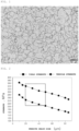
- FIG. 1 a photograph of a microstructure captured with an optical microscope is shown in FIG. 1 .
- the microstructure of the steel sheet is a ferrite single structure, and it could be confirmed that an average ferrite grain size was in a range of 20 to 50 ⁇ m.
- Comparative Example 1 a C content was less than a lower limit specified in the present disclosure, and a value of Free C was insufficient, resulting in continuous yield, and the yield strength was less than 205 MPa.
- Comparative Example 4 showed a case in which the manufacturing conditions of the present disclosure are all satisfied, but a Ti content exceeded an upper limit specified in the present disclosure, and in Comparative Example 5, the Charpy impact transition temperature exceeded -20°C due to the formation of coarse precipitates.
- Comparative Example 5 the yield strength was less than 205 MPa due to an insufficient Si content specified in the present disclosure, and a total content of FeO and Fe 2 SiO 4 in the scale layer was less than 2%, by wt%, confirming that the surface properties were deteriorated.
- a state in which the scale layer is peeled for Comparative Example 5 was shown in FIG. 4 .
Landscapes
- Chemical & Material Sciences (AREA)
- Engineering & Computer Science (AREA)
- Mechanical Engineering (AREA)
- Materials Engineering (AREA)
- Metallurgy (AREA)
- Organic Chemistry (AREA)
- Physics & Mathematics (AREA)
- Thermal Sciences (AREA)
- Crystallography & Structural Chemistry (AREA)
- Chemical Kinetics & Catalysis (AREA)
- Heat Treatment Of Steel (AREA)
Abstract
Description
- The present disclosure relates to a steel material for a seismic damper used to secure seismic resistance of a structure against an earthquake and a manufacturing method of the same.
- In seismic design, which has been mainly used in Korea in the past, a technology of lowering a yield ratio of a steel material used in a structure of a column or beam during an earthquake to delay a point in time at which destruction of the structure occurs, was mainly used. However, the seismic design using such a steel material having a low yield ratio had a problem in that it is impossible to reuse the steel material used in the structure, and the structure itself should be reconstructed due to the absence of securing stability.
- Recently, with the development of seismic design technology, a practical use of a seismic damping or vibration damping structure is progressing. In particular, various technologies for securing seismic performance by absorbing energy applied to a structure by an earthquake to a specific portion thereof are being developed. A seismic damper is used as a device for absorbing such seismic energy, and a steel material for a seismic damper has an ultra-low yield point characteristic. By lowering a yield point of the steel material for the seismic damper further than the existing structural material of a column or a beam, the steel material first yields during an earthquake to absorb vibration energy caused by the earthquake, and suppresses deformation of the structure by maintaining other structural materials within a range of elasticity.
- However, the conventional steel material for the seismic damper utilizes ultra-low carbon steel to have a coarse ferrite structure, thereby exhibiting continuous yield behavior in which a yield point phenomenon is not exhibited during a tensile test. For this reason, while absorbing plastic strain energy generated by the earthquake, work hardening occurs rapidly, and the increase in yield strength is large, so there is a problem to be improved as a steel material for a damper for absorbing earthquake energy.
- However, a technology at a level capable of meeting such high-end demand has not been developed so far.
- (Patent Document 1) Patent Publication No.
2008-0088605 - An aspect of the present disclosure is to provide a steel sheet for a seismic damper, which has a low yield strength and can be used to secure seismic resistance of a structure against an earthquake and a manufacturing method of the same.
- Alternatively, an aspect of the present disclosure is to provide a steel sheet for a seismic damper having a low yield strength and excellent low-temperature impact toughness simultaneously, and a manufacturing method of the same.
- An object of the present disclosure is not limited to the above description. The object of the present disclosure will be understood from the entire content of the present specification, and a person skilled in the art to which the present disclosure pertains will understand an additional object of the present disclosure without difficulty.
- According to an aspect of the present disclosure,
- provided is a steel sheet for a seismic damper, the steel sheet including: a base steel sheet; and
- a scale layer formed on at least one surface of the base steel sheet,
- wherein the base steel sheet includes, by wt%, 0.005 to 0.02% of C, 0.05 to 0.2% of Si, 0.1 to 0.5% of Mn, 0.02% or less of P, 0.01% or less of S, 0.005 to 0.05% of Al, 0.005% or less of N, 0.02 to 0.06% of Nb, 48/14×[N] to 0.05% of Ti, with a balance of Fe and other unavoidable impurities,
- wherein the base steel sheet includes, by area fraction, 95% or more of ferrite as a microstructure,
- wherein a total content of FeO and Fe2SiO4 in the scale layer is 2 to 5%, by wt%.
- According to another aspect of the present disclosure, provided is a manufacturing method of a steel sheet for a seismic damper, the method including:
- reheating a steel slab including, by wt%, 0.005 to 0.02% of C, 0.05 to 0.2% of Si, 0.1 to 0.5% of Mn, 0.02% or less of P, 0.01% or less of S, 0.005 to 0.05% of Al, 0.005% or less of N, 0.02 to 0.06% of Nb, 48/14×[N] to 0.05% of Ti, with a balance of Fe and other unavoidable impurities, to a temperature within a range of 1050 to 1250°C;
- subjecting the reheated steel slab to rough rolling at a temperature of Tnr+50°C or higher, to obtain a rough-rolled bar; and
- hot rolling the rough-rolled bar at Tnr or higher, to obtain a hot-rolled steel sheet.
- As set forth above, according to an aspect of the present disclosure, a steel sheet that can be suitably used for a seismic damper used to secure seismic resistance of a structure against an earthquake and a manufacturing method of the same may be provided.
- Alternatively, according to another aspect of the present disclosure, a steel sheet for a seismic damper having a low yield strength and excellent low-temperature impact toughness and a manufacturing method of the same may be provided.
- Various and beneficial merits and effects of the present disclosure are not limited to the descriptions above, and may be more easily understood in a process of describing specific exemplary embodiments in the present disclosure.
-
-
FIG. 1 illustrates a photograph of a microstructure inside a steel sheet according to an aspect of the present disclosure, captured with an optical microscope. -
FIG. 2 is a graph illustrating a change in yield strength and tensile strength according to a ferrite grain size in a steel material according to the present disclosure. -
FIG. 3 is a graph illustrating a change in yield according to a hot rolling end temperature in the present disclosure. -
FIG. 4 illustrates adhesion of a scale layer formed on a surface of a base steel sheet after completion of rolling in the present disclosure, which is a photograph illustrating a shape of the scale layer dropping due to poor adhesion. -
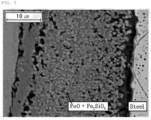
FIG. 5 is an optical photograph illustrating distribution of FeO+Fe2SiO4 in a scale layer formed on an upper layer of the base steel sheet in the present disclosure, as a photograph illustrating a cross-section of the scale layer formed on the surface of the base steel sheet after completion of rolling. - Hereinafter, preferred embodiments of the present disclosure will be described. However, embodiments of the present disclosure may be modified in various forms, and the scope of the present disclosure should not be construed as being limited to the embodiments described below. The present embodiments are provided to those skilled in the art to further elaborate the present disclosure.
- As a steel material used to secure seismic resistance of a structure against an earthquake, conventionally, a technology of using a component close to pure iron and performing an additional heat treatment in a range of 910 to 960°C, has been known. However, since this technology requires performing an additional heat treatment at a high temperature of 900°C or higher after finish rolling, excessive scale occurs in the case of a steel material having an ultra-low yield point to which Si is not added, so that defects occur, or coarse Nb or Ti precipitates are formed, so that there was a problem in that deterioration in impact toughness occurs. In addition, since an additional heat treatment process at a high temperature of 900°C or higher is included, there is also a problem of causing an increase in manufacturing costs.
- Alternatively, as a conventional steel material for a seismic damper, there has been a technology for controlling to have a coarse ferrite structure by utilizing ultra-low carbon steel, but this technology shows continuous yield behavior in which the yield point phenomenon does not occur during a tensile test. For this reason, work hardening occurs rapidly while absorbing plastic strain energy generated by an earthquake, resulting in a large increase in yield strength, so that there was a problem that needs to be improved as a steel sheet for a seismic damper for absorbing earthquake energy.
- Accordingly, as a result of the examples thereof, the present inventors have developed a steel sheet for a seismic damper having a low yield strength and excellent low-temperature impact toughness, exhibiting a yield point phenomenon, resulting in completing a technology that can suppress an increase in yield strength by lowering rapid work hardening due to plastic deformation in the event of an earthquake.
- Specifically, a steel sheet for a seismic damper according to an aspect of the present disclosure includes a base steel plate; and a scale layer formed on at least one surface of the base steel sheet.
- In this case, the base steel sheet may include, by wt%, 0.005 to 0.02% of C, 0.05 to 0.2% of Si, 0.1 to 0.5% of Mn, 0.02% or less of P, 0.01% or less of S, 0.005 to 0.05 % of Al, 0.005% or less of N, 0.02 to 0.06% of Nb, 48/14×[N] to 0.05% of Ti, with a balance of Fe and other unavoidable impurities.
- Hereinafter, a reason for adding each alloy component constituting the composition of the base steel sheet, which is one of the main characteristics of the present invention, and an appropriate content range thereof will be first described.
- C is an element causing solid solution strengthening and is fixed to dislocations in a free state to increase yield strength and decrease elongation. Therefore, in order to be suitably used as a steel material for a seismic damper, a C content needs to be controlled to 0.005% or more, and when the C content exceeds 0.02%, an appropriate strength for use as a seismic damper may be exceeded. Therefore, in the present disclosure, the C content is controlled to be 0.005 to 0.02%. However, more preferably, a lower limit of the C content may be 0.011%, or an upper limit of the C content may be 0.018%.
- Si, like C, is an element causing solid solution strengthening, and increases yield strength and lowers elongation, in order to be suitably used as a steel for a seismic damper, it is preferred to lower a Si content as much as possible. However, if Si is not added in an appropriate amount, adhesion of secondary scale generated during rolling is poor, so that the scale is formed on a surface of the steel sheet during production, increasing possibility of surface defects. Therefore, in the present disclosure, a Si content is controlled to 0.05% or more in terms of securing the adhesion of the secondary scale, and the Si content is controlled to 0.2% or less in terms of securing low yield strength. However, more preferably, a lower limit of the Si content may be 0.07%, or an upper limit of the Si content may be 0.15%.
- Mn, like Si, is an element causing solid solution strengthening, to increase yield strength and lower elongation. Therefore, in order to be suitably used as a steel material for a seismic damper, in the present disclosure, a Mn content is controlled to 0.1% or more in terms of securing appropriate strength, and an upper limit thereof is controlled to 0.5% or less in order to avoid excessive solid solution strengthening effects. However, more preferably, a lower limit of the Mn content may be 0.18%, and the upper limit of the Mn content may be 0.35%.
- P is an element that is advantageous for strength improvement and corrosion resistance, but it can greatly impair impact toughness, so it is preferable to maintain a P content to be as low as possible. Therefore, in the present disclosure, the P content may be controlled to 0.02% or less, more preferably 0.013% or less. In addition, as a lower limit of the P content, 0% may be excluded, considering an inevitably incorporated case, and more preferably, the lower limit of the P content may be 0.0005%.
- Since S is an element that forms MnS, and the like to greatly impair impact toughness, it is preferable to keep an S content as low as possible. Therefore, in the present disclosure, the S content may be controlled to be 0.01% or less, more preferably 0.004% or less. In addition, as a lower limit of the S content, 0% may be excluded considering an inevitably incorporated case, and more preferably, the lower limit of the S content may be 0.0005% or more.
- Al is an element capable of inexpensively deoxidizing molten steel, and an upper limit of an Al content is controlled to 0.05% in terms of securing impact toughness while sufficiently lowering yield strength. Alternatively, more preferably, the upper limit of the Al content may be controlled to 0.035%, and a lower limit of the Al content may be controlled to 0.005% in terms of securing the minimum deoxidation performance. However, more preferably, the lower limit of the Al content may be 0.01%, and the upper limit of the Al content may be 0.035%.
- N is an element causing solid solution strengthening and is fixed to dislocations in a free state to increase yield strength and decrease elongation. Therefore, the lower an N content, the better, so the N content is controlled to be 0.005% or less in terms of securing low yield strength. However, as a lower limit of the N content, 0% may be excluded considering an inevitably incorporated case, and more preferably, the lower limit of the N content may be 0.001% or more.
- Nb is an important element in manufacturing TMCP steel, and is an element precipitated in a form of NbC or NbCN. In addition, Nb dissolved during reheating to a high temperature suppresses recrystallization of austenite, thereby exhibiting an effect of refining the structure.
- Meanwhile, 0.02% or more of Nb is preferably added in order to promote desired deformation of organic precipitates. In addition, it is preferable to add Nb to 0.06% or less in order to prevent deterioration of impact toughness due to coarsening of precipitates. However, more preferably, a lower limit of the Nb content may be 0.03%, and an upper limit of the Nb content may be 0.05%.
- Ti is an element that serves to prevent N from being fixed to dislocations by precipitating in a form of TiN. Therefore, in order to adhere N in steel in an appropriate range, considering the added N content (weight %), Ti should be added in an amount of 48/14×[N]% or more, where [N] refers to a content (weight %) of N in the base steel sheet. Meanwhile, when Ti is excessively added, there is a concern that impact toughness may deteriorate due to coarsening of precipitates, so Ti is controlled to 0.05% or less in terms of securing impact toughness. However, more preferably, a lower limit of the Ti content may be 0.02%, and an upper limit of the Ti content may be 0.045%.
- Meanwhile, although not particularly limited, according to an aspect of the present disclosure, the base steel sheet satisfies the following Relational Expression 1.

- In Relational Expression 1, [C] represents an average content (weight %) of C in the base steel sheet, [Nb] represents an average content (weight %) of Nb in the base steel sheet, and [A] represents a value defined by the following Relational Expression 2.

- In Relational Expression 2, [Ti] represents an average content (weight %) of Ti in the base steel sheet, and [N] represents an average content (weight %) of N in the base steel sheet.
- According to an aspect of the present disclosure, a value of Free C expressed as [C]-12/93×[Nb]-12/48×[A] may be controlled in a range of 0.001 to 0.01%. When the value of Free C described above is less than 0.001%, it may be difficult that a yield point phenomenon is expressed, and the value thereof exceeds 0.01%, there is a risk of exceeding the appropriate strength that can be suitably used for the purpose of the seismic damper. That is, in the present disclosure, by satisfying the Relational Expression 1, it is possible to obtain a steel sheet in which excessive work hardening does not occur when an earthquake occurs by promoting the expression of an upper yield point.
- Therefore, according to the present disclosure, it is possible to provide a steel sheet for a seismic damper having excellent low-temperature impact toughness, having a yield strength in a range of 205 to 245 MPa, a tensile strength of 300 MPa or more, and a Charpy impact transition temperature of -20°C or lower.
- In the present disclosure, remainder is Fe. However, since in the common manufacturing process, unintended impurities may be inevitably incorporated from raw materials or the surrounding environment, the component may not be excluded. Since these impurities are known to any person skilled in the common manufacturing process, the entire contents thereof are not particularly mentioned in the present specification.
- According to an aspect of the present disclosure, the base steel sheet may include by area fraction, 95% or more (more preferably 99% or more) of ferrite as a microstructure, with a balance of 5% or less (including 0%) of other phases such as pearlite, or the like. Alternatively, most preferably, the base steel sheet has a single structure of ferrite (i.e., the base steel sheet includes, by area fraction, 1000 of ferrite as a microstructure. By satisfying this, it is possible to effectively absorb energy when an earthquake occurs and serve as an earthquake damper.
- In addition, although not particularly limited, according to an aspect of the present disclosure, in the base steel sheet, the average ferrite grain size may be in a range of 20 to 50 µm, more preferably 30 to 50 um. In the base steel sheet, if the average ferrite grain size is less than 20 um, a problem of exceeding a target yield strength may occur for use as a seismic damper. In the base steel sheet, when the average ferrite grain size exceeds 50 µm, dislocations can easily move due to the coarse ferrite grain size, resulting in a problem of exhibiting continuous yield behavior.
- Based on a cutting surface of the steel material in the thickness direction (i.e., a direction perpendicular to a rolling direction), the average ferrite grain size described above refers to an average value of values obtained by measuring an equivalent circle diameter of the grains, and specifically, assuming that a spherical particle drawn with the longest length penetrating an inside of the grain as a particle diameter, the average ferrite grain size described above is an average value of the measured grain sizes.
- Meanwhile, according to the present disclosure, a scale layer may be formed on at least one surface of the base steel sheet. In this case, although not particularly limited thereto, the scale layer may refer to a layer formed of FeO, Fe2SiO4, Fe2O3, Fe3O4, oxides of other alloying elements, and the like. depending on conditions in the manufacturing process of the steel sheet.
- According to an aspect of the present disclosure, in the scale layer, a total content of FeO and Fe2SiO4 may be 2 to 5%, by wt%. When the total content of FeO and Fe2SiO4 is less than 2% by wt% with respect to the total content of the scale layer, the adhesion of the scale layer may deteriorate, resulting in irregular peeling of scale on the surface thereof. On the other hand, when the total content of FeO and Fe2SiO4 with respect to the total content of the scale layer exceeds 5%, the yield strength may exceed 245 MPa. In terms of further improving the effect described above, a lower limit of the total content of FeO and Fe2SiO4 with respect to the total content of the scale layer may be 2.28%, or the upper limit of the total content of FeO and Fe2SiO4 with respect to the total content of the scale layer may be 4%.
- Meanwhile, although not particularly limited, according to an aspect of the present disclosure, in order to further improve the effect of providing the steel sheet for a seismic damper securing low yield strength and excellent low-temperature impact toughness and exhibiting the yield point phenomenon, and securing the adhesion of the scale layer to have excellent surface properties, the content of FeO in the scale layer may be 0.5 to 2%, by wt%, and/or the content of Fe2SiO4 in the scale layer may be 1 to 4.5%, by wt%. Alternatively, in terms of maximizing the effect described above, a lower limit of the content of FeO in the scale layer may be 0.79%, or an upper limit of the content of FeO in the scale layer may be 1.5%. Alternatively, in terms of maximizing the effect described above, a lower limit of the content of FeO in the scale layer may be 0.79%, or an upper limit of the content of FeO in the scale layer may be 1.5%.
- In addition, according to an aspect of the present disclosure, a ratio (W1/W2) of a Fe2SiO4 content (W1) and a FeO content (W2) in the scale layer may be 1 to 9. In the scale layer, when the ratio of W1/W2 is less than 1.0, a problem of weakening adhesion of scale due to an insufficient ratio of Fe2SiO4 may occur, and when the ratio of W1/W2 exceeds 9, a problem of red scale may occur on the surface of the steel sheet. In terms of further improving effect described above, a lower limit of the ratio (W1/W2) may be 1.06, or an upper limit of the ratio (W1/W2) may be 4.
- In addition, according to an aspect of the present disclosure, an average thickness of the scale layer may be 10 to 100 um. When the average thickness of the scale layer is less than 10 µm, a problem of weakening the adhesion of the scale may occur, and when the average thickness exceeds 100 um, a problem in processing may occur. Meanwhile, in order to further improve the effect described above, a lower limit of the average thickness of the scale layer may be 31 um, or an upper limit of the average thickness of the scale layer may be 45 um.
- Hereinafter, a manufacturing method of a steel sheet for a seismic damper according to another aspect of the present disclosure will be described in detail. However, the manufacturing method of the steel sheet for a damper a seismic damper of the present disclosure does not necessarily mean that it must be manufactured by the following manufacturing method.
- A manufacturing method of a steel material for a seismic damper according to an aspect of the present disclosure may include an operation of reheating a steel slab satisfying the composition described above, wherein the reheating may be performed to a temperature within a range of 1050 to 1250°C. In this case, a heating temperature of the steel slab is controlled to be 1050°C or higher in order to sufficiently dissolve a carbonitride of Ti and/or Nb formed during casting. However, when heated to an excessively high temperature, there may a concern of coarsening austenite, and it takes an excessive amount of time for a temperature of a surface thereof after rough rolling to reach a cooling start temperature of a surface layer portion, the slab may be preferably heated at 1250°C or lower.
- When reheating the slab described above, oxides generated in a heating furnace may penetrate into a surface of the steel slab and deteriorate adhesion of a finally formed scale layer. Therefore, in order to improve surface quality through securing good adhesion of the scale layer, before a rough rolling operation after the reheating operation, high-pressure water having a pressure of 150 to 200 bars may be provided to the surface of the steel slab to perform a descaling treatment.
- According to an aspect of the present disclosure, before a finish rolling operation to be described later, the reheated steel slab may further include an operation of performing rough rolling to adjust a shape of the slab, and a temperature during rough rolling may be controlled to a temperature at which recrystallization of austenite stops (Tnr)+ 50°C or higher. It is possible to obtain an effect of destroying structural structures such as dentrite, or the like, formed during casting by rough rolling, and it is also possible to obtain an effect of reducing a size of austenite. Meanwhile, more preferably the rough rolling may be performed in a range of 999 to 1155°C.
- Meanwhile, not only in the reheating operation of the slab described above, but also in the rough rolling operation, oxides formed on a surface of the rough-rolled bar may penetrate thereinto and affect adhesion of a finally-formed scale layer. Therefore, in the present disclosure, in order to improve surface quality through securing good adhesion of the scale layer, before a hot rolling operation after the rough rolling operation, high-pressure water having a pressure of 150 to bars may be selectively provided to a surface of the rough-rolled bar, to perform a descaling treatment, and the pressure of the high-pressure water in an operation of the secondary descaling treatment may be controlled to be within a range of 1 to 1.2 times the pressure of the high-pressure water in an operation of the primary descaling treatment. More preferably, the pressure may be controlled to be within a range of 1.02 to 1.2 times.
- The rough-rolled bar described above may be hot-rolled in a temperature range of Tnr or higher, and may be cooled by air cooling after the hot rolling.
- When the hot rolling temperature is lower than Tnr, as illustrated in
FIG. 3 , a large amount of non-uniform deformation zone is introduced into austenite grains to act as a ferrite nucleation site, and fine ferrite is transformed, so that a yield strength may exceed 245 MPa. That is, when the hot rolling temperature is lower than the non-recrystallization stop temperature Tnr, the yield strength exceeds 245 MPa due to a rapid increase in yield strength. Therefore, a rolling end temperature should be higher than the non-recrystallization stop temperature (Tnr). In this case, the Tnr is not separately defined in the present disclosure since a Tnr formula used in normal ultra-low carbon steel is equally applicable. Meanwhile, according to an aspect of the present disclosure, the hot rolling may be performed in a temperature range of 922 to 962°C. - Hereinafter, the present disclosure will be specifically described through the following Examples. However, it should be noted that the following examples are only for describing the present disclosure by illustration, and not intended to limit the right scope of the present disclosure. The reason is that the right scope of the present disclosure is determined by the matters described in the claims and reasonably inferred therefrom.
- A steel slab having the alloy composition and properties illustrated in Table 1 below was prepared. In this case, a content of each component in Table 1 below is represented by wt%, and a balance thereof is Fe and inevitable impurities. That is, in the steel slabs described in Tables 1 and 2 below, Inventive Steels A to D illustrate an example matching a range of alloy compositions defined by the present disclosure, and Comparative Steels E to I illustrate an example deviating from the range of alloy compositions defined by the present disclosure.
- After reheating the prepared steel slab in a temperature range of 1050 to 1250°C, slab reheating - rough rolling -hot rolling were performed under the conditions illustrated in Table 3 below to manufacture a steel material. In this case, before rough rolling after the reheating, high pressure water having a pressure of 150 bars was provided on a surface of the slab to perform a primary descaling treatment, and before hot rolling after the rough rolling, high pressure water having a pressure of 180 bars was provided on a surface of the rough-rolled bar to perform a secondary descaling treatment.
[Table 1] Steel type C Si Mn P S Al Ti Nb N Inventiv e Steel A 0.011 0.12 0.25 0.009 0.003 0.03 0.021 0.04 0.0035 Inventiv e Steel B 0.018 0.15 0.35 0.001 0.004 0.027 0.025 0.03 0.0017 Inventiv e Steel C 0.015 0.08 0.21 0.012 0.002 0.023 0.03 0.05 0.0025 Inventiv e Steel D 0.013 0.07 0.18 0.013 0.003 0.035 0.041 0.03 0.0032 Comparat ive Steel E 0.003 0.1 0.32 0.014 0.002 0.035 0.025 0.04 0.0038 Comparat ive Steel F 0.03 0.15 0.21 0.013 0.001 0.04 0.016 0.05 0.0021 Comparat ive Steel G 0.015 0.35 0.15 0.011 0.003 0.024 0.035 0.01 0.0015 Comparat ive Steel H 0.02 0.09 0.33 0.016 0.004 0.03 0.056 0.02 0.0021 Comparat ive Steel I 0.013 0.01 0.17 0.015 0.002 0.025 0.023 0.03 0.0023 [Table 2] Steel type [A]* Free C* Tnr [°C] Inventiv e Steel A 0.007 0.004 938 Inventiv e Steel B 0.018 0.010 921 Inventiv e Steel C 0.02 0.003 951 Inventiv e Steel D 0.028 0.002 922 Comparat ive Steel E 0.010 -0.005 937 Comparat ive Steel F 0.008 0.022 952 Comparat ive Steel G 0.029 0.006 932 Comparat ive Steel H 0.048 0.005 935 Comparat ive Steel I 0.014 0.006 931 [A]* = [Ti]-48/12×[N]
Free C* = [C]-12/93×[Nb]-12/48×[A][Table 3] Steel type No. Conditions Hot rolling condition Remarks Produc t thickn ess [mm] Slab thickn ess [mm] Reheati ng extract ion tempera ture[°C] Rough rolling end temperat ure[°C] Rolling start temperat ure [°C] Rolling end tempera ture [°C] Invent ive Steel A A-1 30 285 1150 1050 995 939 Recommended conditions A-2 20 295 1115 1035 1021 940 Recommended conditions A-3 35 280 1135 995 945 872 Hot rolling end temperature being less than Tnr Invent ive Steel B B-1 20 280 1175 1015 995 923 Recommended conditions B-2 25 285 1125 1002 985 922 Recommended conditions B-3 30 255 1085 975 915 865 Hot rolling end temperature being less than Tnr Invent ive Steel C C-1 25 285 1155 1155 1085 952 Recommended conditions C-2 20 280 1125 1055 1011 962 Recommended conditions C-3 18 275 1110 1054 970 870 Hot rolling end temperature being less than Tnr Invent ive Steel D D-1 40 295 1135 999 985 925 Recommended conditions D-2 25 285 1145 1010 989 923 Recommended conditions D-3 32 280 1130 995 970 865 Hot rolling end temperature being less than Tnr Compar ative Steel E E-1 40 255 1115 1000 975 938 Recommended conditions Compar ative Steel F F-1 24 290 1135 1095 1020 955 Recommended conditions Compar ative Steel G G-1 15 295 1130 1035 985 935 Recommended conditions Comparative Steel H H-1 25 285 1125 1005 995 940 Recommended Compar ative Steel I I-1 30 290 1135 1015 995 935 Recommended conditions - After manufacturing a steel sheet under the conditions described in Table 3 above, the steel sheet thus obtained was polishing-etched and then observed with an optical microscope. Therefore, it was confirmed that the base steel sheet has a ferrite single structure.
- In addition, the results of measuring an average ferrite grain size, yield strength (YS), tensile strength (TS), and Charpy impact transition temperature of the steel sheet obtained from each Experimental Example were shown in Table 4 below. In this case, target ranges of the yield strength and tensile strength corresponding to the strength characteristic range desired in the present disclosure were shown in
FIG. 2 , together with the ferrite grain size. - In addition, an average thickness of the scale layer was measured by being imaged with an optical microscope to observe the scale layer, which was shown in Table 4 below. In addition, a content of FeO and Fe2SiO4 in the scale layer were measured using a scanning electron microscope and EDS, which was shown in Table 4 below.
- In this case, the average ferrite grain size was measured using a line measurement method, and a point at which yielding occurs using a tensile tester was set to be a yield strength, and a strength when necking occurs was set to be tensile strength. For a Charpy impact transition temperature, an impact absorption energy was measured using a Charpy impact tester and a temperature at which fracture transitions from ductility to brittleness was shown.
- Additionally, in order to evaluate surface properties of the steel sheet, a surface of the steel sheet having an area of 1m2 was observed with a naked eye, and then a peeling area of the scale layer was measured and evaluated according to the following criteria.
- ∘: a peeling area of the scale layer was 20% or less
- △: a peeling area of the scale layer exceeded 20 % and 40% or less
- ×: a peeling area of the scale layer exceeded 20 %
- As can be seen in Table 5, Examples satisfying both the steel composition and manufacturing conditions of the present disclosure, exhibited a yield point phenomenon and physical properties of the steel material had a yield strength of 205 to 245 MPa, tensile strength of 300 MPa or more, and Charpy impact transition temperature of -20°C or lower.
- In addition, in all the steel sheets obtained from the embodiments of the present disclosure, a total content of FeO and Fe2SiO4 in the scale layer satisfies a range of 2 to 5%, by wt%, and thereby, adhesion was excellent without peeling of the scale layer, so excellent surface properties were confirmed. It is determined that this is because SiO2 formed at a boundary between the scale and a base material reacts with FeO to form Fe2SiO4 (Fayalite), which increases binding force between the scale and the base material, resulting in a stable scale state.
- In particular, with respect to the steel sheet obtained from Example 1-1, a photograph of a microstructure captured with an optical microscope is shown in
FIG. 1 . As can be seen inFIG. 1 , the microstructure of the steel sheet is a ferrite single structure, and it could be confirmed that an average ferrite grain size was in a range of 20 to 50 µm. - In addition, with respect to the steel sheet obtained from Example 1-1, after being manufactured so that a cross-section thereof in the thickness direction so that the scale layer can be observed, a photograph captured with an optical microscope was shown in
FIG. 5 . Thereby, it was confirmed that FeO+Fe2SiO4 was included in the scale layer formed on the base steel sheet. - On the other hand, in Comparative Example 1, a C content was less than a lower limit specified in the present disclosure, and a value of Free C was insufficient, resulting in continuous yield, and the yield strength was less than 205 MPa.
- In Comparative Example 2, the C content exceeded the content specified, so that the yield strength exceeded 245 MPa.
- In Comparative Example 3, Si was added excessively, and the yield strength exceeded 245 MPa.
- Comparative Example 4 showed a case in which the manufacturing conditions of the present disclosure are all satisfied, but a Ti content exceeded an upper limit specified in the present disclosure, and in Comparative Example 5, the Charpy impact transition temperature exceeded -20°C due to the formation of coarse precipitates.
- In Comparative Example 5, the yield strength was less than 205 MPa due to an insufficient Si content specified in the present disclosure, and a total content of FeO and Fe2SiO4 in the scale layer was less than 2%, by wt%, confirming that the surface properties were deteriorated. In particular, a state in which the scale layer is peeled for Comparative Example 5 was shown in
FIG. 4 . - In addition, in the case of Reference Examples 1 to 4 satisfying the steel compositions of the present disclosure, but not satisfying the manufacturing conditions thereof, a case in which a hot rolling end temperature is less than Tnr was shown. In such Reference Examples 1 to 4, continuous yield behavior due to introduction of dislocations by rolling in a ferrite region, was shown and yield strengths all exceeded 245 MPa.
- While example embodiments have been shown and described above, it will be apparent to those skilled in the art that modifications and variations could be made without departing from the scope of the present disclosure as defined by the appended claims.
| No. | Division | Base steel sheet | Scale layer | ||||
| Ferrit e fracti on [%] | Average grain size [µm] | FeO content [wt%] | Fe2SiO 4 [wt%] | Total content of FeO and Fe2SiO4 [wt%] | Average thickness of scale layer [µm] | ||
| A-1 | Example 1-1 | 98 | 43 | 1.1 | 2.3 | 3.4 | 38 |
| A-2 | Example 1-2 | 99 | 39 | 1.09 | 2.26 | 3.35 | 34 |
| A-3 | Reference Example 1 | 97 | 22 | 1.08 | 2.3 | 3.38 | 17 |
| B-1 | Example 2-1 | 98 | 43 | 0.85 | 3.15 | 4 | 38 |
| B-2 | Example 2-2 | 99 | 36 | 0.79 | 3.16 | 3.95 | 31 |
| B-3 | Reference Example 2 | 97 | 16 | 0.78 | 3.2 | 3.98 | 11 |
| C-1 | Example 3-1 | 98 | 44 | 1.2 | 1.39 | 2.59 | 39 |
| C-2 | Example 3-2 | 96 | 50 | 1.21 | 1.39 | 2.6 | 45 |
| C-3 | Reference Example 3 | 99 | 20 | 1.3 | 1.31 | 2.61 | 15 |
| D-1 | Example 4-1 | 98 | 39 | 1.05 | 1.23 | 2.28 | 34 |
| D-2 | Example 4-2 | 97 | 43 | 1.11 | 1.18 | 2.29 | 38 |
| D-3 | Reference Example 4 | 97 | 16 | 1.15 | 1.15 | 2.3 | 11 |
| Compa rativ e Steel E | Comparati ve Example 1 | 98 | 44 | 1.3 | 1.69 | 2.99 | 39 |
| Compa rativ e Steel F | Comparati ve Example 2 | 99 | 31 | 1.25 | 1.66 | 2.91 | 26 |
| Compa rativ e Steel G | Comparati ve Example 3 | 98 | 36 | 0.7 | 7.8 | 8.5 | 31 |
| Compa rativ e Steel H | Comparati ve Example 4 | 99 | 45 | 1.12 | 1.72 | 2.84 | 40 |
| Compa rativ e Steel I | Comparati ve Example 5 | 98 | 46 | 0.4 | 0.34 | 0.85 | 85 |
| Division | Occurrence of yield point phenomenon | YS [MPa] | TS [MPa] | Charpy impact transition temperature [°C] | Surface characte ristics evaluati on |
| Example 1-1 | Occur | 212 | 307 | -45 | ○ |
| Example1-2 | Occur | 219 | 313 | -50 | ○ |
| Reference Example 1 | No occur | 265 | 357 | -35 | ○ |
| Example 2-1 | Occur | 214 | 308 | -38 | ○ |
| Example 2-2 | Occur | 224 | 317 | -37 | ○ |
| Reference Example 2 | No occur | 275 | 365 | -40 | ○ |
| Example 3-1 | Occur | 211 | 306 | -37 | ○ |
| Example 3-2 | Occur | 202 | 300 | -41 | ○ |
| Reference Example 3 | No occur | 275 | 369 | -28 | ○ |
| Example 4-1 | Occur | 219 | 313 | -37 | ○ |
| Example 4-2 | Occur | 214 | 308 | -51 | ○ |
| Reference Example 4 | No occur | 296 | 354 | -41 | ○ |
| Comparative Example 1 | No occur | 203 | 306 | -26 | ○ |
| Comparative Example 2 | Occur | 255 | 345 | -21 | ○ |
| Comparative Example 3 | Occur | 263 | 352 | -25 | ○ |
| Comparative Example 4 | Occur | 196 | 305 | -8 | ○ |
| Comparative Example 5 | Occur | 193 | 301 | -23 | × |
Claims (14)
- A steel sheet for a seismic damper, comprising:a base steel sheet; anda scale layer formed on at least one surface of the base steel sheet,wherein the base steel sheet includes, by wt%, 0.005 to 0.02% of C, 0.05 to 0.2% of Si, 0.1 to 0.5% of Mn, 0.02% or less of P, 0.01% or less of S, 0.005 to 0.05% of Al, 0.005% or less of N, 0.02 to 0.06% of Nb, 48/14×[N] to 0.05% of Ti, with a balance of Fe and other unavoidable impurities,wherein a total content of FeO and Fe2SiO4 in the scale layer is 2 to 5%, by wt%.
- The steel sheet for a seismic damper of claim 1, wherein a microstructure of the base steel sheet is a ferrite single structure.
- The steel sheet for a seismic damper of claim 2, wherein the average ferrite grain size is 20 to 50 µm.
- The steel sheet for a seismic damper of claim 1, wherein the base steel sheet satisfies the following Relational Expression 1,


- The steel sheet for a seismic damper of claim 1, wherein a content of FeO in the scale layer is 0.5 to 2%, by wt%.
- The steel sheet for a seismic damper of claim 1, wherein a content of Fe2SiO4 in the scale layer is 1 to 4.5%, by wt%.
- The steel sheet for a seismic damper of claim 1, wherein a ratio (W1/W2) of the content (W1) of Fe2SiO4 and the content (W2) of FeO in the scale layer is 1 to 9.
- The steel sheet for a seismic damper of claim 1, wherein the scale layer has an average thickness of 10 to 100 µm.
- The steel sheet for a seismic damper of claim 1, wherein the steel sheet has a yield strength of 205 to 245 MPa.
- The steel sheet for a seismic damper of claim 1, wherein the steel sheet has a tensile strength of 300 MPa or more.
- The steel sheet for a seismic damper of claim 1, wherein the steel sheet has a Charpy impact transition temperature of -20°C or lower.
- A manufacturing method of a steel sheet for a seismic damper, comprising:reheating a steel slab including, by wt%, 0.005 to 0.02% of C, 0.05 to 0.2% of Si, 0.1 to 0.5% of Mn, 0.02% or less of P, 0.01% or less of S, 0.005 to 0.05% of Al, 0.005% or less of N, 0.02 to 0.06% of Nb, 48/14×[N] to 0.05% of Ti, with a balance of Fe and other unavoidable impurities, to a temperature within a range of 1050 to 1250°C;subjecting the reheated steel slab to rough rolling at a temperature of Tnr+50°C or higher, to obtain a rough-rolled bar; andhot rolling the rough-rolled bar at Tnr or higher, to obtain a hot-rolled steel sheet.
- The manufacturing method of a steel sheet for a seismic damper of claim 12, further comprising: before rough rolling, after the reheating operation,
performing a descaling treatment of providing high-pressure water having a pressure of 150 to 200 bars to a surface of the steel slab. - The manufacturing method of a steel sheet for a seismic damper of claim 13, further comprising:before hot rolling after the rough rolling operation,performing a secondary descaling treatment of providing high-pressure water having a pressure of 150 to 200 bars to a surface of the rough-rolled bar,wherein the pressure of high-pressure water in the secondary descaling treatment is controlled to be within a range of 1 to 1.2 times the pressure of the high-pressure water in the primary descaling treatment.
Applications Claiming Priority (2)
| Application Number | Priority Date | Filing Date | Title |
|---|---|---|---|
| KR1020200179049A KR102488496B1 (en) | 2020-12-18 | 2020-12-18 | Steel sheet for seismic damper having superior toughness property and manufacturing method of the same |
| PCT/KR2021/017872 WO2022131618A1 (en) | 2020-12-18 | 2021-11-30 | Steel sheet for seismic damper having superior toughness property and manufacturing method of same |
Publications (2)
| Publication Number | Publication Date |
|---|---|
| EP4265762A1 true EP4265762A1 (en) | 2023-10-25 |
| EP4265762A4 EP4265762A4 (en) | 2025-07-23 |
Family
ID=82059213
Family Applications (1)
| Application Number | Title | Priority Date | Filing Date |
|---|---|---|---|
| EP21906923.4A Pending EP4265762A4 (en) | 2020-12-18 | 2021-11-30 | Steel sheet for seismic damper with superior toughness and manufacturing processes therefor |
Country Status (6)
| Country | Link |
|---|---|
| US (1) | US20240052451A1 (en) |
| EP (1) | EP4265762A4 (en) |
| JP (1) | JP7762721B2 (en) |
| KR (1) | KR102488496B1 (en) |
| CN (1) | CN116635552B (en) |
| WO (1) | WO2022131618A1 (en) |
Family Cites Families (18)
| Publication number | Priority date | Publication date | Assignee | Title |
|---|---|---|---|---|
| JP3411217B2 (en) * | 1998-05-29 | 2003-05-26 | 新日本製鐵株式会社 | Low yield point steel with high yield ratio and excellent base metal and weld toughness |
| JP3774577B2 (en) | 1998-10-05 | 2006-05-17 | 新日本製鐵株式会社 | Low yield point steel for vibration control devices |
| JP4177539B2 (en) | 2000-03-28 | 2008-11-05 | 新日本製鐵株式会社 | Manufacturing method of laser welding steel |
| JP4438600B2 (en) * | 2004-10-28 | 2010-03-24 | 住友金属工業株式会社 | Hot-rolled steel strip and manufacturing method thereof |
| JP4705508B2 (en) | 2006-04-17 | 2011-06-22 | 新日本製鐵株式会社 | Low yield point steel for damper and manufacturing method thereof |
| PL1985533T3 (en) | 2007-02-09 | 2021-08-02 | Sekisui Chemical Co., Ltd. | Vibration damping material and vibration damping structure |
| JP4705601B2 (en) * | 2007-03-29 | 2011-06-22 | 新日本製鐵株式会社 | Low yield point steel for dampers with excellent toughness and method for producing the same |
| CN101775535B (en) * | 2009-01-13 | 2012-03-28 | 宝山钢铁股份有限公司 | 160MPa earthquake-proof low yield strength steel, steel plate and manufacturing method thereof |
| JP2011189394A (en) * | 2010-03-16 | 2011-09-29 | Nisshin Steel Co Ltd | Method for manufacturing hot rolled steel sheet having excellent surface property |
| JP5534319B2 (en) * | 2010-03-25 | 2014-06-25 | 日新製鋼株式会社 | Method for producing hot-rolled steel sheet with excellent pickling and workability |
| KR20120132839A (en) * | 2011-05-30 | 2012-12-10 | 현대제철 주식회사 | Structural damper steel with low yield ratio and method of manufacturing the same |
| JP6101132B2 (en) * | 2012-04-20 | 2017-03-22 | 株式会社神戸製鋼所 | Manufacturing method of steel materials with excellent resistance to hydrogen-induced cracking |
| KR101482359B1 (en) * | 2012-12-27 | 2015-01-13 | 주식회사 포스코 | Method for manufacturing high strength steel plate having excellent toughness and low-yield ratio property |
| CN103710622A (en) * | 2013-12-20 | 2014-04-09 | 钢铁研究总院 | 690MPa-yield-strength low-yield-tensile-ratio antiseismic steel and manufacturing method thereof |
| WO2017183133A1 (en) * | 2016-04-20 | 2017-10-26 | 新日鐵住金株式会社 | Hot-rolled steel sheet, steel, and container |
| CN106636924B (en) * | 2016-12-30 | 2018-04-03 | 武钢集团昆明钢铁股份有限公司 | A kind of building structure of 235MPa ranks earthquake-resistant hot rolled steel plate, steel band and preparation method thereof |
| KR102246956B1 (en) * | 2017-04-07 | 2021-04-29 | 제이에프이 스틸 가부시키가이샤 | Blackened hot rolled steel sheet and its manufacturing method |
| CN209674071U (en) * | 2019-04-24 | 2019-11-22 | 艾景奇 | A kind of electric power communication optical cable downlead Anti-freezing protection pipe |
-
2020
- 2020-12-18 KR KR1020200179049A patent/KR102488496B1/en active Active
-
2021
- 2021-11-30 EP EP21906923.4A patent/EP4265762A4/en active Pending
- 2021-11-30 WO PCT/KR2021/017872 patent/WO2022131618A1/en not_active Ceased
- 2021-11-30 CN CN202180084766.0A patent/CN116635552B/en active Active
- 2021-11-30 JP JP2023535596A patent/JP7762721B2/en active Active
- 2021-11-30 US US18/267,674 patent/US20240052451A1/en active Pending
Also Published As
| Publication number | Publication date |
|---|---|
| WO2022131618A1 (en) | 2022-06-23 |
| JP2023554331A (en) | 2023-12-27 |
| KR102488496B1 (en) | 2023-01-13 |
| EP4265762A4 (en) | 2025-07-23 |
| US20240052451A1 (en) | 2024-02-15 |
| KR20220088225A (en) | 2022-06-27 |
| CN116635552B (en) | 2026-01-06 |
| CN116635552A (en) | 2023-08-22 |
| JP7762721B2 (en) | 2025-10-30 |
Similar Documents
| Publication | Publication Date | Title |
|---|---|---|
| EP2264205B1 (en) | High-strength steel plate excellent in low-temperature toughness, steel pipe, and processes for production of both | |
| EP2272994A1 (en) | High-tensile strength steel and manufacturing method thereof | |
| EP2623625B1 (en) | Steel plate for pipe line, having excellent hydrogen induced crack resistance, and preparation method thereof | |
| KR100799421B1 (en) | 490MPa-resistance-ratio cold-formed steel pipe with excellent weldability and manufacturing method | |
| KR102379443B1 (en) | Steel material for hot press forming, hot pressed member and manufacturing method theerof | |
| EP3480332B1 (en) | High strength steel plate having excellent low yield ratio characteristics and low temperature toughness and method for manufacturing same | |
| JP3499084B2 (en) | Low yield ratio high tensile strength steel for construction with excellent brittle crack arrestability and method of manufacturing the same | |
| JPH1017982A (en) | Low yield ratio high tensile strength steel for construction with excellent fracture resistance and method of manufacturing the same | |
| JP7221475B6 (en) | High-strength steel material with excellent ductility and low-temperature toughness, and method for producing the same | |
| JP4344073B2 (en) | High strength steel excellent in high temperature strength and method for producing the same | |
| KR20250011608A (en) | Non-alloyed wire with excellent cutting properties and impact toughness and its manufacturing method | |
| JP3817887B2 (en) | High toughness high strength steel and method for producing the same | |
| KR100833076B1 (en) | High-strength resistive ratio structural steel with excellent low temperature toughness and brittle crack propagation stopping characteristics, and its manufacturing method | |
| JP7265008B2 (en) | Steel material for pressure vessel excellent in resistance to hydrogen-induced cracking and its manufacturing method | |
| KR100711371B1 (en) | Thick sheet for line pipe with excellent cryogenic toughness and manufacturing method | |
| EP4265762A1 (en) | Steel sheet for seismic damper having superior toughness property and manufacturing method of same | |
| EP4438761A1 (en) | Hot-rolled steel sheet and method for manufacturing same | |
| KR102255829B1 (en) | Steel sheet for seismic damper having superior toughness property and manufacturing method of the same | |
| KR100723156B1 (en) | Yield strength 552 MPA line pipes with excellent deformability and brittle fracture stopping characteristics and manufacturing method | |
| KR100833075B1 (en) | High-strength resistive ratio structural steel with excellent low temperature toughness and brittle crack propagation stopping characteristics, and its manufacturing method | |
| JP3376195B2 (en) | Method for producing high-strength thick steel sheet with excellent in-plate homogeneity and having both brittle crack propagation arrestability and weldability | |
| EP4261304A1 (en) | Steel material for seismic damper having superior impact toughness, and manufacturing method for same | |
| EP4265795A1 (en) | Ultrathick steel plate having excellent low-temperature impact toughness and method for manufacturing same | |
| KR102181788B1 (en) | High strength medium carbon steel for earthquake-proof and its manufacturing method | |
| KR100508513B1 (en) | Method for manufacturing hot rolled steel sheet having high strength and toughness |
Legal Events
| Date | Code | Title | Description |
|---|---|---|---|
| STAA | Information on the status of an ep patent application or granted ep patent |
Free format text: STATUS: THE INTERNATIONAL PUBLICATION HAS BEEN MADE |
|
| PUAI | Public reference made under article 153(3) epc to a published international application that has entered the european phase |
Free format text: ORIGINAL CODE: 0009012 |
|
| STAA | Information on the status of an ep patent application or granted ep patent |
Free format text: STATUS: REQUEST FOR EXAMINATION WAS MADE |
|
| 17P | Request for examination filed |
Effective date: 20230627 |
|
| AK | Designated contracting states |
Kind code of ref document: A1 Designated state(s): AL AT BE BG CH CY CZ DE DK EE ES FI FR GB GR HR HU IE IS IT LI LT LU LV MC MK MT NL NO PL PT RO RS SE SI SK SM TR |
|
| DAV | Request for validation of the european patent (deleted) | ||
| DAX | Request for extension of the european patent (deleted) | ||
| REG | Reference to a national code |
Ref country code: DE Ref legal event code: R079 Free format text: PREVIOUS MAIN CLASS: C22C0038000000 Ipc: C21D0008020000 |
|
| A4 | Supplementary search report drawn up and despatched |
Effective date: 20250624 |
|
| RIC1 | Information provided on ipc code assigned before grant |
Ipc: C21D 8/02 20060101AFI20250617BHEP Ipc: C21D 9/46 20060101ALI20250617BHEP Ipc: C22C 38/02 20060101ALI20250617BHEP Ipc: C22C 38/04 20060101ALI20250617BHEP Ipc: C22C 38/12 20060101ALI20250617BHEP Ipc: C22C 38/14 20060101ALI20250617BHEP Ipc: C23C 8/10 20060101ALI20250617BHEP |