EP4265504A1 - Independent system for inspection, monitoring and surveillance of long infrastructure and the environment thereof - Google Patents
Independent system for inspection, monitoring and surveillance of long infrastructure and the environment thereof Download PDFInfo
- Publication number
- EP4265504A1 EP4265504A1 EP22742312.6A EP22742312A EP4265504A1 EP 4265504 A1 EP4265504 A1 EP 4265504A1 EP 22742312 A EP22742312 A EP 22742312A EP 4265504 A1 EP4265504 A1 EP 4265504A1
- Authority
- EP
- European Patent Office
- Prior art keywords
- inspection
- autonomous mobile
- surveillance
- monitoring
- environment
- Prior art date
- Legal status (The legal status is an assumption and is not a legal conclusion. Google has not performed a legal analysis and makes no representation as to the accuracy of the status listed.)
- Pending
Links
Images





Classifications
-
- B—PERFORMING OPERATIONS; TRANSPORTING
- B64—AIRCRAFT; AVIATION; COSMONAUTICS
- B64U—UNMANNED AERIAL VEHICLES [UAV]; EQUIPMENT THEREFOR
- B64U50/00—Propulsion; Power supply
- B64U50/30—Supply or distribution of electrical power
- B64U50/37—Charging when not in flight
-
- F—MECHANICAL ENGINEERING; LIGHTING; HEATING; WEAPONS; BLASTING
- F17—STORING OR DISTRIBUTING GASES OR LIQUIDS
- F17D—PIPE-LINE SYSTEMS; PIPE-LINES
- F17D5/00—Protection or supervision of installations
-
- B—PERFORMING OPERATIONS; TRANSPORTING
- B61—RAILWAYS
- B61L—GUIDING RAILWAY TRAFFIC; ENSURING THE SAFETY OF RAILWAY TRAFFIC
- B61L23/00—Control, warning or like safety means along the route or between vehicles or trains
- B61L23/04—Control, warning or like safety means along the route or between vehicles or trains for monitoring the mechanical state of the route
-
- B—PERFORMING OPERATIONS; TRANSPORTING
- B61—RAILWAYS
- B61L—GUIDING RAILWAY TRAFFIC; ENSURING THE SAFETY OF RAILWAY TRAFFIC
- B61L27/00—Central railway traffic control systems; Trackside control; Communication systems specially adapted therefor
- B61L27/50—Trackside diagnosis or maintenance, e.g. software upgrades
- B61L27/53—Trackside diagnosis or maintenance, e.g. software upgrades for trackside elements or systems, e.g. trackside supervision of trackside control system conditions
-
- B—PERFORMING OPERATIONS; TRANSPORTING
- B64—AIRCRAFT; AVIATION; COSMONAUTICS
- B64U—UNMANNED AERIAL VEHICLES [UAV]; EQUIPMENT THEREFOR
- B64U50/00—Propulsion; Power supply
- B64U50/30—Supply or distribution of electrical power
- B64U50/37—Charging when not in flight
- B64U50/38—Charging when not in flight by wireless transmission
-
- B—PERFORMING OPERATIONS; TRANSPORTING
- B64—AIRCRAFT; AVIATION; COSMONAUTICS
- B64U—UNMANNED AERIAL VEHICLES [UAV]; EQUIPMENT THEREFOR
- B64U70/00—Launching, take-off or landing arrangements
- B64U70/90—Launching from or landing on platforms
-
- B—PERFORMING OPERATIONS; TRANSPORTING
- B64—AIRCRAFT; AVIATION; COSMONAUTICS
- B64U—UNMANNED AERIAL VEHICLES [UAV]; EQUIPMENT THEREFOR
- B64U70/00—Launching, take-off or landing arrangements
- B64U70/90—Launching from or landing on platforms
- B64U70/99—Means for retaining the UAV on the platform, e.g. dogs or magnets
-
- B—PERFORMING OPERATIONS; TRANSPORTING
- B61—RAILWAYS
- B61L—GUIDING RAILWAY TRAFFIC; ENSURING THE SAFETY OF RAILWAY TRAFFIC
- B61L25/00—Recording or indicating positions or identities of vehicles or trains or setting of track apparatus
- B61L25/06—Indicating or recording the setting of track apparatus, e.g. of points, of signals
-
- B—PERFORMING OPERATIONS; TRANSPORTING
- B64—AIRCRAFT; AVIATION; COSMONAUTICS
- B64U—UNMANNED AERIAL VEHICLES [UAV]; EQUIPMENT THEREFOR
- B64U2101/00—UAVs specially adapted for particular uses or applications
- B64U2101/25—UAVs specially adapted for particular uses or applications for manufacturing or servicing
- B64U2101/26—UAVs specially adapted for particular uses or applications for manufacturing or servicing for manufacturing, inspections or repairs
-
- B—PERFORMING OPERATIONS; TRANSPORTING
- B64—AIRCRAFT; AVIATION; COSMONAUTICS
- B64U—UNMANNED AERIAL VEHICLES [UAV]; EQUIPMENT THEREFOR
- B64U2101/00—UAVs specially adapted for particular uses or applications
- B64U2101/30—UAVs specially adapted for particular uses or applications for imaging, photography or videography
- B64U2101/31—UAVs specially adapted for particular uses or applications for imaging, photography or videography for surveillance
-
- F—MECHANICAL ENGINEERING; LIGHTING; HEATING; WEAPONS; BLASTING
- F17—STORING OR DISTRIBUTING GASES OR LIQUIDS
- F17D—PIPE-LINE SYSTEMS; PIPE-LINES
- F17D3/00—Arrangements for supervising or controlling working operations
-
- H—ELECTRICITY
- H02—GENERATION; CONVERSION OR DISTRIBUTION OF ELECTRIC POWER
- H02G—INSTALLATION OF ELECTRIC CABLES OR LINES, OR OF COMBINED OPTICAL AND ELECTRIC CABLES OR LINES
- H02G1/00—Methods or apparatus specially adapted for installing, maintaining, repairing or dismantling electric cables or lines
- H02G1/02—Methods or apparatus specially adapted for installing, maintaining, repairing or dismantling electric cables or lines for overhead lines or cables
Definitions
- This invention relates to a system for the inspection of infrastructures based on the installation of an autonomous mobile device capable of being displaced in a self-propelled manner on an auxiliary line.
- the system allows the inspection, monitoring and surveillance of long linear infrastructures (railroad lines, oil pipelines, power lines, etc.) and the environment thereof.
- This infrastructure inspection system is based on the installation of a grooved auxiliary line from which there hangs an autonomous mobile device capable of being displaced in a self-propelled manner, i.e., it is a system independent of the infrastructure to be inspected.
- the equipment, drone or autonomous mobile device is coupled to a grooved auxiliary line that ensures its anchoring, the traction thereon and its release, if necessary, for example, for maintenance.
- the autonomous mobile device has a system for propulsion in order to cause the displacement thereof on the grooved auxiliary line and to then run along all or part of the infrastructure to be inspected.
- the major advantages of the system are its greater operability in all weather conditions, greater safety against the risk of falling on the infrastructure and the environment thereof and the reduction of the qualification requirements for operators.
- the grooved auxiliary line consists of a cable the section of which has some type of guiding groove, which allows the coupling of the autonomous mobile device such that it allows the longitudinal displacement thereof along the cable and the ability to stop at any point along the path.
- the core of the auxiliary line can also replace some of the cables that are installed in overhead lines as protection, power, signaling or communications cables.
- ground or guard cable which is an aluminum-steel alloy cable (typically LA 110) which connects surge arresters, fittings, poles and grounding points to shunt surges (lightning, discharges, etc.) to ground.
- auxiliary cable could act as an optical fiber cable for communications or signaling.
- a third option consists of one of the cores of the auxiliary cable consisting of a series of conductors providing power (by contact or induction) to the drone continuously or semicontinuously (frequent intervals) or serving as a channel for transmitting information between the drone and the control center.
- the fixing system for fixing the autonomous mobile device in the grooved auxiliary line allows the traction of autonomous mobile device on the cable, enabling displacement while at the same time its design prevents it from being able to be accidentally released, which provides complete security.
- a key feature of the system is that the design of the grooved auxiliary line and of the autonomous mobile device cause said grooved auxiliary line to be able to be anchored to a mount without hindering the displacement of the autonomous mobile device.
- the autonomous mobile device can move freely along the grooved auxiliary line, without the clamping supports of said line requiring a particular actuation on the part of the autonomous mobile device upon passing through the supports.
- An important aspect of the system is the existence of a charging station for the autonomous mobile device which allows its parking and controlled docking, the establishment of electrical contact for charging the autonomous mobile device and a subsystem for connection to and protection of the power grid.
- the charging stations can also provide radio communication link functionality for the autonomous equipment.
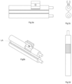
- Figure 1a shows an exemplary layout of this system, which repeats along the entire path.
- Figure 1b shows in detail the assembly of components forming the system for inspection of infrastructures. It is based on the installation of an autonomous mobile device DM capable of being displaced in a self-propelled manner on a grooved auxiliary line LA for performing inspection, monitoring and surveillance tasks as a result of the sensing equipment it incorporates.
- an autonomous mobile device DM capable of being displaced in a self-propelled manner on a grooved auxiliary line LA for performing inspection, monitoring and surveillance tasks as a result of the sensing equipment it incorporates.
- a key feature of the invention is that the design of the grooved auxiliary line LA and of the autonomous mobile device allow said grooved auxiliary line to be able to be anchored or suspended from a mount, such as columns, supports or facings, without hindering the displacement of the autonomous mobile device along the guiding groove. It is therefore independent of the layout to be inspected.
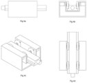
- Figure 2 shows the detail of the grooved auxiliary line LA.
- Figure 3 shows the autonomous mobile device DM.
- This device incorporates a system for propulsion which is coupled to the grooved auxiliary line by a guiding groove RA for the displacement of the device, ensuring its anchoring, the traction thereon and its release, if necessary, for example, for maintenance.
- the grooved aerial auxiliary line LA is fixed by means of an anchoring fitting, for example a clamp, allowing the rolling elements R to transmit the movement of the autonomous mobile device DM using the inner surface of the guiding groove RA, as seen in Figure 3 .
- the autonomous mobile device is thereby able to move freely along the grooved auxiliary line, without the clamping supports of said line requiring a particular actuation on the part of the autonomous mobile device so as to allow it to pass through same.
- the grooved auxiliary line LA consists of a cable having a grooved section which allows the coupling of the autonomous mobile device such that it can be displaced longitudinally along the cable. Since it is a cable, it can be suspended from two points, forming a very long span, without intermediate supports.
- Figure 3 explains the fixing system, where it can be seen that the autonomous mobile device moves on the grooved auxiliary line, enabling the displacement, as well as preventing it from being able to be accidentally released.
- the traction system In order to propel the autonomous mobile device through the grooved auxiliary line, the traction system has a series of rolling elements R, which are displaced by the vertical guiding surface, as seen in Figure 3 , rotating about the vertical shaft thereof, operated by a motor incorporated in the frame of the autonomous mobile device.
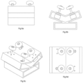
- the guiding surface prefferably be horizontal, with the rolling elements rotating about the horizontal shaft thereof, as seen in Figure 4 .
- the rolling elements being arranged in pairs on a mount transverse to the grooved auxiliary line, such that they rotate freely on the frame of the autonomous mobile device and their displacement can accommodate the curvature of the auxiliary line.
- the angle of orientation of the rolling elements can be selected for the purpose of accommodating different choices of guiding surface of the grooved auxiliary line.
- the latter may adopt widely varying configurations and geometric shapes, as shown in Figures 8 to 16 .
- the cable of the grooved auxiliary line LA may be manufactured from different materials based on the configuration of the autonomous mobile device and its weight and on the characteristics of the line on which it is installed, such as the length of spans, the characteristics of the supports, the applicable legal requirements, etc.
- the system has an electronic system for control of the autonomous mobile device which controls all the subsystems and receives instructions from the remote control, in addition to a power system, including a battery powering the drone and a recharging system and a charge sensor.
- Another aspect of the invention relates to a system for control and remote supervision of the autonomous mobile device which allows providing it with instructions for parking, displacement, charging, navigation, collection of information, actuation of auxiliary devices, as well as for receiving and viewing the information generated by onboard systems.
- the autonomous mobile device DM incorporates a subsystem for navigation and locating of the autonomous mobile device based on a GPS system, a revolution counter for each rolling element in contact with the cable as a complement to navigation and for internal diagnostics, a gyroscope and accelerometer as a complement to navigation and for internal diagnostics and for the auxiliary line, a communications module for both the remote control of the drone and for the sending of information.
- the autonomous mobile device DM likewise incorporates a subsystem for monitoring and inspection of the infrastructure with the ability to incorporate, as required, the following: cameras, thermal cameras, laser measurement devices, ultrasound sensors, gas sensors, a subsystem with the ability to incorporate auxiliary devices such as megaphones, flame throwers or sprays, and a mount to incorporate other additional subsystems.
Landscapes
- Engineering & Computer Science (AREA)
- Aviation & Aerospace Engineering (AREA)
- Mechanical Engineering (AREA)
- Chemical & Material Sciences (AREA)
- Combustion & Propulsion (AREA)
- General Engineering & Computer Science (AREA)
- Computer Networks & Wireless Communication (AREA)
- Health & Medical Sciences (AREA)
- Biomedical Technology (AREA)
- General Health & Medical Sciences (AREA)
- Control Of Position, Course, Altitude, Or Attitude Of Moving Bodies (AREA)
- Monitoring And Testing Of Nuclear Reactors (AREA)
Abstract
Description
- This invention relates to a system for the inspection of infrastructures based on the installation of an autonomous mobile device capable of being displaced in a self-propelled manner on an auxiliary line. The system allows the inspection, monitoring and surveillance of long linear infrastructures (railroad lines, oil pipelines, power lines, etc.) and the environment thereof.
- Today, there are a number of very long infrastructures (railways, high and low voltage overhead lines, lighting and communication lines, gas pipelines, etc.) which, for operational safety reasons, must be inspected with visual means and other technologies to ensure their integrity and general good condition.
- The deployment of devices along the infrastructure is, at present, a complex and expensive solution given the drawbacks for supplying, communicating and maintaining said devices to the scale that would be needed in order to provide coverage to said infrastructure.
- It is for this reason that the possibility of providing more cost-effective but also equally efficient automated systems for said tasks, such as Unmanned Aerial Systems, has recently been the object of study.
- In the field of overhead power lines, line inspection robots have been introduced. These robots are, in fact, an extension of the personnel displacement solution which allows ground personnel to deploy a robot on one or more conductors of the overhead line which, as it moves along the line, inspects the condition of the cables. As an inventive element, these robots are able to circumvent the insulator strings that interrupt the natural movement of the robot between one span of the line and another. Once the robot has inspected a section of line, it is retrieved by the ground personnel and returned to its base. Given the aforementioned limitations of design and use, such systems cannot be considered as assimilable to the object of the present invention. There is a wide variety of patents that describe functionalities similar to those of this invention, but some are based on flying drones such as those described in patent
US2018170414 or in Korean patentKR101958266 US2018170414 orU82018297699 JP2016056682 WO2004070902 . - However, there are no solutions based on the layout of independent auxiliary lines with autonomous mobile devices which are displaced on same by means of guiding grooves, so as not to interfere with the normal operation of the line to be inspected, nor having to avoid objects that may collide with the device.
- This infrastructure inspection system is based on the installation of a grooved auxiliary line from which there hangs an autonomous mobile device capable of being displaced in a self-propelled manner, i.e., it is a system independent of the infrastructure to be inspected. The equipment, drone or autonomous mobile device is coupled to a grooved auxiliary line that ensures its anchoring, the traction thereon and its release, if necessary, for example, for maintenance. The autonomous mobile device has a system for propulsion in order to cause the displacement thereof on the grooved auxiliary line and to then run along all or part of the infrastructure to be inspected.
- The major advantages of the system are its greater operability in all weather conditions, greater safety against the risk of falling on the infrastructure and the environment thereof and the reduction of the qualification requirements for operators.
- The grooved auxiliary line consists of a cable the section of which has some type of guiding groove, which allows the coupling of the autonomous mobile device such that it allows the longitudinal displacement thereof along the cable and the ability to stop at any point along the path.
- The core of the auxiliary line can also replace some of the cables that are installed in overhead lines as protection, power, signaling or communications cables. In particular the so-called ground or guard cable, which is an aluminum-steel alloy cable (typically LA 110) which connects surge arresters, fittings, poles and grounding points to shunt surges (lightning, discharges, etc.) to ground.
- Another option is that the auxiliary cable could act as an optical fiber cable for communications or signaling.
- A third option consists of one of the cores of the auxiliary cable consisting of a series of conductors providing power (by contact or induction) to the drone continuously or semicontinuously (frequent intervals) or serving as a channel for transmitting information between the drone and the control center.
- The fixing system for fixing the autonomous mobile device in the grooved auxiliary line allows the traction of autonomous mobile device on the cable, enabling displacement while at the same time its design prevents it from being able to be accidentally released, which provides complete security.
- A key feature of the system is that the design of the grooved auxiliary line and of the autonomous mobile device cause said grooved auxiliary line to be able to be anchored to a mount without hindering the displacement of the autonomous mobile device. Thus, the autonomous mobile device can move freely along the grooved auxiliary line, without the clamping supports of said line requiring a particular actuation on the part of the autonomous mobile device upon passing through the supports.
- An important aspect of the system is the existence of a charging station for the autonomous mobile device which allows its parking and controlled docking, the establishment of electrical contact for charging the autonomous mobile device and a subsystem for connection to and protection of the power grid. The charging stations can also provide radio communication link functionality for the autonomous equipment.
-
-
Figure 1a depicts a possible layout of the independent anchoring system in a section repeating along its entire path.Figure 1b is the detail of a mooring pole for the layout, of how the grooved auxiliary line hangs from it and of the autonomous mobile device that is displaced supported on the grooved auxiliary line. -
Figures 2a, 2b, 2c and 2d are perspective, front and top views of the grooved auxiliary line, together with a section of its physical structure. -
Figures 3a, 3b, 3c and 3d depict several perspective, front, side and top views of the autonomous mobile device. -
Figures 4 ,5 and6 correspond with movable devices similar to that ofFigure 3 , but for different applications.Figures 4a, 4b, 4c and 4d depict different views of a variant of the device where the guiding surface is horizontal, with the rolling elements rotating about the horizontal shaft thereof.Figures 5a, 5b, 5c and 5d depict different views of a variant of the device, where the rolling elements are arranged in pairs, such that the displacement can accommodate the curvature of the auxiliary line.Figures 6a, 6b, 6c and 6d show views of a variant such that the device can accommodate different angles of orientation of the rolling elements and therefore different guiding surfaces. -
Figure 7 depicts a motor-shaft-rolling element assembly of the autonomous mobile device connected to the grooved auxiliary line. -
Figures 8 to 16 show different configurations of the grooved auxiliary line, as appropriate for each application. -
Figure 1a shows an exemplary layout of this system, which repeats along the entire path.Figure 1b shows in detail the assembly of components forming the system for inspection of infrastructures. It is based on the installation of an autonomous mobile device DM capable of being displaced in a self-propelled manner on a grooved auxiliary line LA for performing inspection, monitoring and surveillance tasks as a result of the sensing equipment it incorporates. - A key feature of the invention is that the design of the grooved auxiliary line LA and of the autonomous mobile device allow said grooved auxiliary line to be able to be anchored or suspended from a mount, such as columns, supports or facings, without hindering the displacement of the autonomous mobile device along the guiding groove. It is therefore independent of the layout to be inspected.
-
Figure 2 shows the detail of the grooved auxiliary line LA.Figure 3 shows the autonomous mobile device DM. This device incorporates a system for propulsion which is coupled to the grooved auxiliary line by a guiding groove RA for the displacement of the device, ensuring its anchoring, the traction thereon and its release, if necessary, for example, for maintenance. - The grooved aerial auxiliary line LA is fixed by means of an anchoring fitting, for example a clamp, allowing the rolling elements R to transmit the movement of the autonomous mobile device DM using the inner surface of the guiding groove RA, as seen in
Figure 3 . The autonomous mobile device is thereby able to move freely along the grooved auxiliary line, without the clamping supports of said line requiring a particular actuation on the part of the autonomous mobile device so as to allow it to pass through same. - The grooved auxiliary line LA consists of a cable having a grooved section which allows the coupling of the autonomous mobile device such that it can be displaced longitudinally along the cable. Since it is a cable, it can be suspended from two points, forming a very long span, without intermediate supports.
-
Figure 3 explains the fixing system, where it can be seen that the autonomous mobile device moves on the grooved auxiliary line, enabling the displacement, as well as preventing it from being able to be accidentally released. - In order to propel the autonomous mobile device through the grooved auxiliary line, the traction system has a series of rolling elements R, which are displaced by the vertical guiding surface, as seen in
Figure 3 , rotating about the vertical shaft thereof, operated by a motor incorporated in the frame of the autonomous mobile device. - It is also possible for the guiding surface to be horizontal, with the rolling elements rotating about the horizontal shaft thereof, as seen in
Figure 4 . - As can be seen in
Figure 5 , other possible variants consist of the rolling elements being arranged in pairs on a mount transverse to the grooved auxiliary line, such that they rotate freely on the frame of the autonomous mobile device and their displacement can accommodate the curvature of the auxiliary line. Likewise, as shown inFigure 6 , the angle of orientation of the rolling elements can be selected for the purpose of accommodating different choices of guiding surface of the grooved auxiliary line. - To enable the release of the autonomous mobile device and its removal from the grooved auxiliary line of the motor-shaft-rolling element assembly, it can be laterally displaced, as shown in
Figure 7 . - To allow the displacement of the autonomous mobile device along the grooved auxiliary line, the latter may adopt widely varying configurations and geometric shapes, as shown in
Figures 8 to 16 . - The cable of the grooved auxiliary line LA may be manufactured from different materials based on the configuration of the autonomous mobile device and its weight and on the characteristics of the line on which it is installed, such as the length of spans, the characteristics of the supports, the applicable legal requirements, etc.
- The system has an electronic system for control of the autonomous mobile device which controls all the subsystems and receives instructions from the remote control, in addition to a power system, including a battery powering the drone and a recharging system and a charge sensor.
- Another aspect of the invention relates to a system for control and remote supervision of the autonomous mobile device which allows providing it with instructions for parking, displacement, charging, navigation, collection of information, actuation of auxiliary devices, as well as for receiving and viewing the information generated by onboard systems.
- The autonomous mobile device DM incorporates a subsystem for navigation and locating of the autonomous mobile device based on a GPS system, a revolution counter for each rolling element in contact with the cable as a complement to navigation and for internal diagnostics, a gyroscope and accelerometer as a complement to navigation and for internal diagnostics and for the auxiliary line, a communications module for both the remote control of the drone and for the sending of information.
- The autonomous mobile device DM likewise incorporates a subsystem for monitoring and inspection of the infrastructure with the ability to incorporate, as required, the following: cameras, thermal cameras, laser measurement devices, ultrasound sensors, gas sensors, a subsystem with the ability to incorporate auxiliary devices such as megaphones, flame throwers or sprays, and a mount to incorporate other additional subsystems.
Claims (8)
- An independent system for the inspection, monitoring and surveillance of long infrastructures and the environment thereof, which is based on a movable device with systems for propulsion and control of the device, power and recharging systems and navigation and positioning systems, and which is able to inspect the infrastructure and communicate with a remote control, characterized by being formed by• an autonomous mobile device DM including rolling elements R• a grooved auxiliary line LA, which consists of a cable comprising a guiding groove RA.
- The independent system for the inspection, monitoring and surveillance of long infrastructures and the environment thereof according to claim 1, characterized in that the rolling elements R of the autonomous mobile device transmit their movement using the inner surface of the guiding groove RA.
- The independent system for the inspection, monitoring and surveillance of long infrastructures and the environment thereof according to claim 2, characterized in that the surface along which the autonomous mobile device DM moves can be vertical, with the rolling elements R rotating about the vertical shaft thereof, or said surface can be horizontal, with the rolling elements R rotating about the horizontal shaft thereof.
- The independent system for the inspection, monitoring and surveillance of long infrastructures and the environment thereof according to any of the preceding claims, characterized in that the rolling elements R can be arranged in pairs on a mount transverse to the grooved auxiliary line LA, which rotates freely on the frame of the autonomous mobile equipment, such that the displacement thereof can accommodate the curvature of the auxiliary line LA.
- The independent system for the inspection, monitoring and surveillance of long infrastructures and the environment thereof according to any of the preceding claims, characterized in that the angle of orientation of the rolling elements R can be selected for the purpose of accommodating different choices of the surface along which the autonomous mobile device DM moves.
- The independent system for the inspection, monitoring and surveillance of long infrastructures and the environment thereof according to any of the preceding claims, characterized by being independent of the structure to be inspected, which allows being suspended from columns, supports or facings without interfering with the displacement of the autonomous mobile device along the guiding groove.
- The independent system for the inspection, monitoring and surveillance of long infrastructures and the environment thereof according to claim 1, characterized by a core of the auxiliary line formed by one or more conductors or optical fiber based on the functional and mechanical characteristics of the line.
- The independent system for the inspection, monitoring and surveillance of long infrastructures and the environment thereof according to claim 1, characterized by a core of the auxiliary line consisting of a metallic conductor, of the required materials and size based on the electrical and mechanical characteristics of the line, which may be connected to the poles, fittings, surge arresters, and the remaining protective devices of the line.
Applications Claiming Priority (2)
| Application Number | Priority Date | Filing Date | Title |
|---|---|---|---|
| ES202130075U ES1271675Y (en) | 2021-01-19 | 2021-01-19 | INDEPENDENT SYSTEM FOR THE INSPECTION, MONITORING AND SURVEILLANCE OF LARGE INFRASTRUCTURES AND THEIR ENVIRONMENT |
| PCT/ES2022/070011 WO2022157401A1 (en) | 2021-01-19 | 2022-01-14 | Independent system for inspection, monitoring and surveillance of long infrastructure and the environment thereof |
Publications (2)
| Publication Number | Publication Date |
|---|---|
| EP4265504A1 true EP4265504A1 (en) | 2023-10-25 |
| EP4265504A4 EP4265504A4 (en) | 2025-01-08 |
Family
ID=76478888
Family Applications (1)
| Application Number | Title | Priority Date | Filing Date |
|---|---|---|---|
| EP22742312.6A Pending EP4265504A4 (en) | 2021-01-19 | 2022-01-14 | Independent system for inspection, monitoring and surveillance of long infrastructure and the environment thereof |
Country Status (4)
| Country | Link |
|---|---|
| US (1) | US20240302003A1 (en) |
| EP (1) | EP4265504A4 (en) |
| ES (1) | ES1271675Y (en) |
| WO (1) | WO2022157401A1 (en) |
Families Citing this family (1)
| Publication number | Priority date | Publication date | Assignee | Title |
|---|---|---|---|---|
| ES1271675Y (en) * | 2021-01-19 | 2021-10-06 | Fuenteblandor Holding S L | INDEPENDENT SYSTEM FOR THE INSPECTION, MONITORING AND SURVEILLANCE OF LARGE INFRASTRUCTURES AND THEIR ENVIRONMENT |
Family Cites Families (14)
| Publication number | Priority date | Publication date | Assignee | Title |
|---|---|---|---|---|
| JPH10248130A (en) * | 1997-02-28 | 1998-09-14 | Toshiba Corp | Overhead traveling device and control method thereof |
| CA2418473A1 (en) | 2003-02-04 | 2004-08-04 | Hydro-Quebec | Robot vehicle that runs on conductors and has the ability to negotiate obstacles using temporary support rotors |
| CA2745815C (en) * | 2010-02-10 | 2015-04-28 | Electric Power Research Institute, Inc. | Line inspection robot and system |
| SG194257A1 (en) * | 2012-04-26 | 2013-11-29 | Yik Hei Sia | Power generating windbags and water-bags |
| JP6272289B2 (en) | 2015-12-17 | 2018-01-31 | 日鉄住金鋼板株式会社 | Connection structure between support member and lower folded plate roof, support member used for the same, and holding member for the support member |
| CN106451212B (en) * | 2016-10-26 | 2018-11-02 | 江西电力职业技术学院 | A kind of overhead transmission line inspection car and power transmission line polling system |
| US10597054B2 (en) | 2016-12-15 | 2020-03-24 | Progress Rail Locomotive Inc. | Real-time drone infrared inspection of moving train |
| US20180297699A1 (en) * | 2017-04-18 | 2018-10-18 | Mesa Digital, Llc | Overhead tethered drone system |
| US10461512B2 (en) * | 2017-05-11 | 2019-10-29 | General Cable Technologies Corporation | Systems and methods for aerial treatment of overhead cabling |
| KR101958266B1 (en) | 2018-05-04 | 2019-03-14 | (주)지엠시스텍 | Inspection system of overhead power line and its inspection method |
| MX2021015023A (en) * | 2019-06-07 | 2022-02-21 | Kyte Dynamics Inc | SUSPENDED SYSTEM OF AIR VEHICLE WITH PROPELLER STABILIZATION. |
| CN212195167U (en) * | 2020-05-29 | 2020-12-22 | 中铁二院工程集团有限责任公司 | Automatic inspection device for electrified railway contact network |
| ES1271675Y (en) * | 2021-01-19 | 2021-10-06 | Fuenteblandor Holding S L | INDEPENDENT SYSTEM FOR THE INSPECTION, MONITORING AND SURVEILLANCE OF LARGE INFRASTRUCTURES AND THEIR ENVIRONMENT |
| CN113904263B (en) * | 2021-10-11 | 2023-03-03 | 成都聚合智创科技有限公司 | On-line obstacle crossing walking device and inspection robot |
-
2021
- 2021-01-19 ES ES202130075U patent/ES1271675Y/en active Active
-
2022
- 2022-01-14 US US18/273,109 patent/US20240302003A1/en active Pending
- 2022-01-14 EP EP22742312.6A patent/EP4265504A4/en active Pending
- 2022-01-14 WO PCT/ES2022/070011 patent/WO2022157401A1/en not_active Ceased
Also Published As
| Publication number | Publication date |
|---|---|
| ES1271675Y (en) | 2021-10-06 |
| US20240302003A1 (en) | 2024-09-12 |
| WO2022157401A1 (en) | 2022-07-28 |
| ES1271675U (en) | 2021-06-24 |
| EP4265504A4 (en) | 2025-01-08 |
Similar Documents
| Publication | Publication Date | Title |
|---|---|---|
| Menendez et al. | Robotics in power systems: Enabling a more reliable and safe grid | |
| US4904996A (en) | Line-mounted, movable, power line monitoring system | |
| Flammini et al. | Railway infrastructure monitoring by drones | |
| US11764553B2 (en) | Smart power transmission line inspection system | |
| Toussaint et al. | Transmission line maintenance robots capable of crossing obstacles: State‐of‐the‐art review and challenges ahead | |
| US8666553B2 (en) | Line inspection robot and system | |
| JP2017131019A (en) | Power transmission facility inspection system | |
| EP2751534B1 (en) | System for monitoring electric supply lines | |
| JP7201416B2 (en) | Continuity inspection method for pull-down conductor in blade of wind power generator | |
| EP3486179B1 (en) | Inpecting utilities by means of an unmanned aerial vehicle and charging a rechargeable battery of the vehicle in flight using a high voltage power line and method and apparatus for generating a flight plan for the vehicle | |
| US20240302003A1 (en) | Independent system for inspection, monitoring and surveillance of long infrastructure and the environment thereof | |
| WO2020026057A1 (en) | Temperature monitoring electrical cable coupler | |
| EP4540138B1 (en) | Uas system for carrying out tasks or activities on targets arranged at a certain height from the ground | |
| Montambault et al. | About the future of power line robotics | |
| KR102468546B1 (en) | Electric power supply apparatus management system for telegraph pole using IoT | |
| Rymer et al. | A review of unmanned aerial vehicle technology in power line inspection | |
| EP2888085B1 (en) | Unmanned vehicle for system supervision | |
| US12060173B2 (en) | Aerial vehicle with magnetic field power generation unit and tower including charging port | |
| KR101661500B1 (en) | Underwater connection assembly with earthing unit | |
| RU2287910C1 (en) | Method and overhead telecommunication platform for organizing regional wireless data-transfer networks | |
| EP3430693B1 (en) | Smart spacer and method for overhead transmission line monitoring | |
| WO2024147141A1 (en) | Bird deflector aerial deployment device and method | |
| CA2745815C (en) | Line inspection robot and system | |
| KR101928909B1 (en) | ESE Lightning Rod for Guard Wire of the High Voltage Electrical Transmission Line | |
| DK178375B1 (en) | Power supply for an electric component in a wind turbine blade |
Legal Events
| Date | Code | Title | Description |
|---|---|---|---|
| STAA | Information on the status of an ep patent application or granted ep patent |
Free format text: STATUS: THE INTERNATIONAL PUBLICATION HAS BEEN MADE |
|
| PUAI | Public reference made under article 153(3) epc to a published international application that has entered the european phase |
Free format text: ORIGINAL CODE: 0009012 |
|
| STAA | Information on the status of an ep patent application or granted ep patent |
Free format text: STATUS: REQUEST FOR EXAMINATION WAS MADE |
|
| 17P | Request for examination filed |
Effective date: 20230719 |
|
| AK | Designated contracting states |
Kind code of ref document: A1 Designated state(s): AL AT BE BG CH CY CZ DE DK EE ES FI FR GB GR HR HU IE IS IT LI LT LU LV MC MK MT NL NO PL PT RO RS SE SI SK SM TR |
|
| DAV | Request for validation of the european patent (deleted) | ||
| DAX | Request for extension of the european patent (deleted) | ||
| A4 | Supplementary search report drawn up and despatched |
Effective date: 20241211 |
|
| RIC1 | Information provided on ipc code assigned before grant |
Ipc: F17D 3/00 20060101ALI20241205BHEP Ipc: B64U 101/26 20230101ALI20241205BHEP Ipc: B64U 70/99 20230101ALI20241205BHEP Ipc: B64U 70/90 20230101ALI20241205BHEP Ipc: B64U 50/38 20230101ALI20241205BHEP Ipc: B64U 50/37 20230101ALI20241205BHEP Ipc: B61L 27/53 20220101ALI20241205BHEP Ipc: H02G 1/02 20060101ALI20241205BHEP Ipc: B61L 23/04 20060101AFI20241205BHEP |
|
| STAA | Information on the status of an ep patent application or granted ep patent |
Free format text: STATUS: EXAMINATION IS IN PROGRESS |
|
| 17Q | First examination report despatched |
Effective date: 20251031 |