EP4265490A1 - Hydraulic pressure control device and straddle-type vehicle - Google Patents
Hydraulic pressure control device and straddle-type vehicle Download PDFInfo
- Publication number
- EP4265490A1 EP4265490A1 EP21824023.2A EP21824023A EP4265490A1 EP 4265490 A1 EP4265490 A1 EP 4265490A1 EP 21824023 A EP21824023 A EP 21824023A EP 4265490 A1 EP4265490 A1 EP 4265490A1
- Authority
- EP
- European Patent Office
- Prior art keywords
- control device
- hydraulic pressure
- pressure control
- mounting hole
- base body
- Prior art date
- Legal status (The legal status is an assumption and is not a legal conclusion. Google has not performed a legal analysis and makes no representation as to the accuracy of the status listed.)
- Pending
Links
- 239000012530 fluid Substances 0.000 claims abstract description 107
- 238000003860 storage Methods 0.000 claims abstract description 5
- 230000007423 decrease Effects 0.000 claims description 15
- 239000007788 liquid Substances 0.000 claims description 12
- 238000003825 pressing Methods 0.000 claims description 4
- 238000001514 detection method Methods 0.000 description 18
- 230000001276 controlling effect Effects 0.000 description 10
- 238000010586 diagram Methods 0.000 description 10
- 238000012986 modification Methods 0.000 description 7
- 230000004048 modification Effects 0.000 description 7
- 238000004519 manufacturing process Methods 0.000 description 6
- 230000003247 decreasing effect Effects 0.000 description 4
- 230000000694 effects Effects 0.000 description 3
- 230000005611 electricity Effects 0.000 description 3
- 238000012544 monitoring process Methods 0.000 description 2
- 229910000838 Al alloy Inorganic materials 0.000 description 1
- 238000007599 discharging Methods 0.000 description 1
- 238000009826 distribution Methods 0.000 description 1
- 230000000977 initiatory effect Effects 0.000 description 1
- 238000010248 power generation Methods 0.000 description 1
- 230000001172 regenerating effect Effects 0.000 description 1
- 230000001105 regulatory effect Effects 0.000 description 1
- 239000004575 stone Substances 0.000 description 1
- 239000000725 suspension Substances 0.000 description 1
Images


Classifications
-
- B—PERFORMING OPERATIONS; TRANSPORTING
- B62—LAND VEHICLES FOR TRAVELLING OTHERWISE THAN ON RAILS
- B62L—BRAKES SPECIALLY ADAPTED FOR CYCLES
- B62L3/00—Brake-actuating mechanisms; Arrangements thereof
- B62L3/02—Brake-actuating mechanisms; Arrangements thereof for control by a hand lever
- B62L3/023—Brake-actuating mechanisms; Arrangements thereof for control by a hand lever acting on fluid pressure systems
-
- B—PERFORMING OPERATIONS; TRANSPORTING
- B60—VEHICLES IN GENERAL
- B60T—VEHICLE BRAKE CONTROL SYSTEMS OR PARTS THEREOF; BRAKE CONTROL SYSTEMS OR PARTS THEREOF, IN GENERAL; ARRANGEMENT OF BRAKING ELEMENTS ON VEHICLES IN GENERAL; PORTABLE DEVICES FOR PREVENTING UNWANTED MOVEMENT OF VEHICLES; VEHICLE MODIFICATIONS TO FACILITATE COOLING OF BRAKES
- B60T8/00—Arrangements for adjusting wheel-braking force to meet varying vehicular or ground-surface conditions, e.g. limiting or varying distribution of braking force
- B60T8/17—Using electrical or electronic regulation means to control braking
- B60T8/1701—Braking or traction control means specially adapted for particular types of vehicles
- B60T8/1706—Braking or traction control means specially adapted for particular types of vehicles for single-track vehicles, e.g. motorcycles
-
- B—PERFORMING OPERATIONS; TRANSPORTING
- B62—LAND VEHICLES FOR TRAVELLING OTHERWISE THAN ON RAILS
- B62J—CYCLE SADDLES OR SEATS; AUXILIARY DEVICES OR ACCESSORIES SPECIALLY ADAPTED TO CYCLES AND NOT OTHERWISE PROVIDED FOR, e.g. ARTICLE CARRIERS OR CYCLE PROTECTORS
- B62J27/00—Safety equipment
-
- B—PERFORMING OPERATIONS; TRANSPORTING
- B62—LAND VEHICLES FOR TRAVELLING OTHERWISE THAN ON RAILS
- B62J—CYCLE SADDLES OR SEATS; AUXILIARY DEVICES OR ACCESSORIES SPECIALLY ADAPTED TO CYCLES AND NOT OTHERWISE PROVIDED FOR, e.g. ARTICLE CARRIERS OR CYCLE PROTECTORS
- B62J45/00—Electrical equipment arrangements specially adapted for use as accessories on cycles, not otherwise provided for
- B62J45/40—Sensor arrangements; Mounting thereof
- B62J45/41—Sensor arrangements; Mounting thereof characterised by the type of sensor
Definitions
- the present invention relates to a hydraulic pressure control device used in a brake system equipped in a straddle-type vehicle and a straddle-type vehicle provided with the hydraulic pressure control device.
- a straddle-type vehicle is provided with a brake system capable of executing anti-lock brake control, which is to control the braking force of a vehicle wheel by controlling the hydraulic pressure of a brake fluid.
- the brake system includes a hydraulic pressure control device.
- a hydraulic pressure control device in which a base body having an internal flow path through which a brake fluid flows and a master cylinder are integrated with each other has been proposed as a hydraulic pressure control device of the related art used in a brake system capable of executing anti-lock brake control (see PTL 1).
- the internal flow path as a part of a brake flow path allowing the master cylinder and a wheel cylinder to communicate with each other is formed in the master cylinder-integrated base body. Also formed in the master cylinder-integrated base body are a piston mounting hole where the piston of the master cylinder is provided so as to be capable of reciprocating, a reservoir tank for brake fluid storage connected to the piston mounting hole, an inlet valve mounting hole where an inlet valve is provided, and an outlet valve mounting hole where an outlet valve is provided.
- the inlet valve opens and closes the part of the internal flow path through which the brake fluid flowing from the piston mounting hole to the wheel cylinder passes.
- the outlet valve opens and closes the part of the internal flow path through which the brake fluid flowing from the wheel cylinder to an accumulator (part storing the brake fluid released from the wheel cylinder during pressure decrease in anti-lock brake control) passes.
- the hydraulic pressure control device provided with the master cylinder-integrated base body the piston of the master cylinder is pressed by a rider gripping a brake lever with his or her hand. Accordingly, the hydraulic pressure control device provided with the master cylinder-integrated base body is mounted to the handlebar of a straddle-type vehicle.
- the inlet valve mounting hole and the outlet valve mounting hole are formed in the base body so as to extend in a substantially horizontal direction with the hydraulic pressure control device mounted to the handlebar.
- the inlet valve mounting hole and the outlet valve mounting hole are open to the front, rear, or side of the straddle-type vehicle when the hydraulic pressure control device is mounted to the handlebar.
- a housing storing a coil as an inlet valve drive source, a coil as an outlet valve drive source, and a control board controlling the energization of the coils is disposed so as to face the surface of the base body where the inlet valve mounting hole and the outlet valve mounting hole are open.
- the hydraulic pressure control device of the related art provided with the master cylinder-integrated base body it is imperative to ensure a housing disposition space in front of, behind, or beside the hydraulic pressure control device in mounting the hydraulic pressure control device on the handlebar.
- various objects are provided in front of, behind, and beside the mounting position of the hydraulic pressure control device. Accordingly, the hydraulic pressure control device of the related art provided with the master cylinder-integrated base body is problematic in that the degree of freedom of mounting on a straddle-type vehicle is low.
- the present invention has been made in view of the above, and an object of the present invention is to obtain a hydraulic pressure control device with which the degree of freedom of mounting on a straddle-type vehicle can be improved as compared with the related art. Another object of the present invention is to obtain a straddle-type vehicle provided with such a hydraulic pressure control device.
- a hydraulic pressure control device is used in a brake system capable of executing anti-lock brake control and mounted to a handlebar of a straddle-type vehicle.
- the hydraulic pressure control device has a configuration in which a brake fluid released from a wheel cylinder during pressure decrease in the anti-lock brake control is stored in an accumulator and the brake fluid in the accumulator is pumplessly discharged out of the accumulator and includes: a master cylinder-integrated base body where a piston mounting hole where a piston of a master cylinder is provided so as to be capable of reciprocating, a reservoir tank for brake fluid storage connected to the piston mounting hole, and an internal flow path as a part of a brake fluid flow path allowing the piston mounting hole and the wheel cylinder to communicate with each other are formed; an inlet valve provided in an inlet valve mounting hole formed in the base body so as to be capable of reciprocating and opening and closing a part of the internal flow path through which a brake fluid flowing from the piston mounting hole to the wheel cylinder passes; and an outlet valve provided in an
- a straddle-type vehicle according to the present invention includes the hydraulic pressure control device according to the present invention.
- the inlet valve mounting hole and the outlet valve mounting hole are open on the second surface opposite to the opening portion of the reservoir tank.
- the surface of the base body where the opening portion of the reservoir tank is formed faces upward.
- the second surface of the base body faces downward. Accordingly, when the hydraulic pressure control device according to the present invention is mounted to the handlebar of the straddle-type vehicle, a coil, a control board, and a housing are disposed below the base body.
- the straddle-type vehicle there is a spatial margin in the vertical direction around the mounting position of the hydraulic pressure control device as compared with the front, rear, and side where various objects are provided. Accordingly, the degree of freedom of mounting on the straddle-type vehicle is improved as compared with the related art with the hydraulic pressure control device according to the present invention.
- the present invention may be adopted for a straddle-type vehicle other than a bicycle.
- the straddle-type vehicle means every vehicle ridden by a straddling rider.
- Examples of the straddle-type vehicle other than a bicycle include an automatic two-wheeled vehicle, an automatic three-wheeled vehicle, and a buggy using at least one of an engine and an electric motor as a drive source.
- the bicycle means every vehicle that can be propelled on the road by pedal effort.
- the bicycle includes ordinary, electrically assisted, and electric bicycles.
- the automatic two-wheeled or three-wheeled vehicle means a so-called motorcycle and the motorcycle includes an autobike, a scooter, and an electric scooter.
- the brake system according to the present invention includes front wheel-side and rear wheel-side hydraulic pressure control devices for executing anti-lock brake control on front and rear wheels, respectively.
- the brake system according to the present invention may include only one of the front wheel-side hydraulic pressure control device and the rear wheel-side hydraulic pressure control device.
- the brake system according to the present invention may, for example, execute anti-lock brake control on both the front and rear wheels using one hydraulic pressure control device.
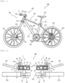
- Fig. 1 is a side view illustrating a schematic configuration of the bicycle equipped with the brake system according to the embodiment of the present invention.
- Fig. 2 is a plan view illustrating the periphery of a handlebar of the bicycle equipped with the brake system according to the embodiment of the present invention.
- the left side of the page is the front of a bicycle 200 in Fig. 1 .
- the upper side of the page is the front of the bicycle 200.
- Fig. 2 illustrates a state where brake levers 241 are not gripped by a rider.
- a front wheel-side hydraulic pressure control device 1 and a rear wheel-side hydraulic pressure control device 2 are illustrated in cross section in part.
- the bicycle 200 equipped with a brake system 100 includes a frame 210, a turning portion 230, a saddle 218, a pedal 219, a rear wheel 220, a rear wheel-side braking portion 252, and a brake lamp 221.
- the frame 210 includes, for example, a head tube 211 axially supporting a steering column 231 of the turning portion 230, a top tube 212 and a down tube 213 connected to the head tube 211, a seat tube 214 connected to the top tube 212 and the down tube 213 and holding the saddle 218, and a stay 215 connected to the upper and lower ends of the seat tube 214 and holding the rear wheel 220 and the rear wheel-side braking portion 252.
- the turning portion 230 includes, for example, the steering column 231, a handle stem 232 held by the steering column 231, a handlebar 233 held by the handle stem 232, the brake levers 241 provided around the handlebar 233, front forks 216 connected to the steering column 231, a front wheel 217 rotatably held by the front forks 216, and a front wheel-side braking portion 251.
- the front forks 216 are provided on both sides of the front wheel 217. One end of the front forks 216 is connected to the steering column 231, and the other end of the front forks 216 is connected to the center of rotation of the front wheel 217. In other words, the front wheel 217 is rotatably held between the pair of front forks 216.
- the front fork 216 may be a front fork equipped with a suspension system.
- the bicycle 200 includes the two brake levers 241.
- the brake system 100 includes the front wheel-side hydraulic pressure control device 1 for executing anti-lock brake control on the front wheel 217 and the rear wheel-side hydraulic pressure control device 2 for executing anti-lock brake control on the rear wheel 220.
- the front wheel-side hydraulic pressure control device 1 and the rear wheel-side hydraulic pressure control device 2 include master cylinder-integrated base bodies 10 as will be described later.
- a hydraulic pressure control device provided with a master cylinder-integrated base body is mounted to a handlebar and has a configuration in which the piston of the master cylinder is pressed by a brake lever hand-gripped by a rider.
- the bicycle 200 includes the brake lever 241 for the front wheel-side hydraulic pressure control device 1 and the brake lever 241 for the rear wheel-side hydraulic pressure control device 2.
- one of the front wheel-side hydraulic pressure control device 1 and the rear wheel-side hydraulic pressure control device 2 is provided around one grip portion 234 (grip portion 234 on the left side), which the rider grips with his or her left hand, of the handlebar 233.
- the other of the front wheel-side hydraulic pressure control device 1 and the rear wheel-side hydraulic pressure control device 2 is provided around the other grip portion 234 (grip portion 234 on the right side), which the rider grips with his or her right hand, of the handlebar 233.
- Fig. 2 illustrates an example in which the rear wheel-side hydraulic pressure control device 2 is provided around the grip portion 234 that the rider grips with his or her left hand and the front wheel-side hydraulic pressure control device 1 is provided around the grip portion 234 that the rider grips with his or her right hand.
- a power source unit 260 as a power source for the front wheel-side hydraulic pressure control device 1 and the rear wheel-side hydraulic pressure control device 2 is mounted to, for example, the down tube 213 of the frame 210.
- the power source unit 260 may be a battery or a generator.
- the generator include a generator generating electricity by the bicycle 200 traveling (such as a hub dynamo generating electricity by the front wheel 217 or the rear wheel 220 rotating and a generator performing regenerative power generation as an electric motor of a drive source for the front wheel 217 or the rear wheel 220) and a generator generating electricity from sunlight.
- the bicycle 200 is equipped with the brake system 100 including at least the brake lever 241, the front wheel-side braking portion 251, the rear wheel-side braking portion 252, the front wheel-side hydraulic pressure control device 1, the rear wheel-side hydraulic pressure control device 2, and the power source unit 260.
- the brake system 100 is capable of executing anti-lock brake control on the front wheel 217 by controlling the pressure of the brake fluid of the front wheel-side braking portion 251 with the front wheel-side hydraulic pressure control device 1.
- the brake system 100 is capable of executing anti-lock brake control on the rear wheel 220 by controlling the pressure of the brake fluid of the rear wheel-side braking portion 252 with the rear wheel-side hydraulic pressure control device 2.
- the brake lamp 221 emits light when at least one of the front wheel 217 and the rear wheel 220 is braked.
- Fig. 3 is a diagram illustrating a schematic configuration of the brake system according to the embodiment of the present invention.
- the brake system 100 includes the front wheel-side hydraulic pressure control device 1 and the rear wheel-side hydraulic pressure control device 2.
- the front wheel-side hydraulic pressure control device 1 and the rear wheel-side hydraulic pressure control device 2 include the master cylinder-integrated base bodies 10.
- the base body 10 is formed with a piston mounting hole 21 where a piston 51 of a master cylinder 50 is provided so as to be capable of reciprocating.
- the master cylinder 50 is configured by the piston mounting hole 21 and the piston 51.
- the base body 10 is formed with a wheel cylinder port 45 and an internal flow path 40 allowing the piston mounting hole 21 and the wheel cylinder port 45 to communicate with each other.
- the base body 10 is formed with a reservoir tank 52 for brake fluid storage connected to the piston mounting hole 21.
- the internal flow path 40 is a brake fluid flow path.
- the internal flow path 40 includes, for example, a first flow path 41, a second flow path 42, a third flow path 43, and a fourth flow path 44.
- the piston mounting hole 21 of the master cylinder 50 and the wheel cylinder port 45 communicate with each other via the first flow path 41 and the second flow path 42.
- the inlet-side end portion of the third flow path 43 is connected to the middle portion of the second flow path 42.
- the front wheel-side braking portion 251 is connected via a liquid pipe 101 to the wheel cylinder port 45 of the base body 10 of the front wheel-side hydraulic pressure control device 1.
- the front wheel-side braking portion 251 includes a wheel cylinder 253 and a rotor 254.
- the wheel cylinder 253 of the front wheel-side braking portion 251 is mounted to, for example, the front fork 216.
- the wheel cylinder 253 of the front wheel-side braking portion 251 includes a piston portion (not illustrated) moving in conjunction with the pressure of the liquid pipe 101 and is connected to the outlet side of the second flow path 42 of the front wheel-side hydraulic pressure control device 1 via the liquid pipe 101 and the wheel cylinder port 45.
- the wheel cylinder port 45 of the base body 10 of the front wheel-side hydraulic pressure control device 1 is connected to the liquid pipe 101 communicating with the wheel cylinder 253 of the front wheel-side braking portion 251.
- the rotor 254 of the front wheel-side braking portion 251 is held by the front wheel 217 and rotates together with the front wheel 217.
- a brake pad (not illustrated) is pressed against the rotor 254 of the front wheel-side braking portion 251 and the front wheel 217 is braked.
- the rear wheel-side braking portion 252 is connected via the liquid pipe 101 to the wheel cylinder port 45 of the base body 10 of the rear wheel-side hydraulic pressure control device 2.
- the rear wheel-side braking portion 252 includes the wheel cylinder 253 and the rotor 254 as in the case of the front wheel-side braking portion 251.
- the wheel cylinder 253 of the rear wheel-side braking portion 252 is mounted to, for example, the stay 215.
- the wheel cylinder 253 of the rear wheel-side braking portion 252 includes a piston portion (not illustrated) moving in conjunction with the pressure of the liquid pipe 101 and is connected to the outlet side of the second flow path 42 of the rear wheel-side hydraulic pressure control device 2 via the liquid pipe 101 and the wheel cylinder port 45.
- the wheel cylinder port 45 of the base body 10 of the rear wheel-side hydraulic pressure control device 2 is connected to the liquid pipe 101 communicating with the wheel cylinder 253 of the rear wheel-side braking portion 252.
- the rotor 254 of the rear wheel-side braking portion 252 is held by the rear wheel 220 and rotates together with the rear wheel 220.
- a brake pad (not illustrated) is pressed against the rotor 254 of the rear wheel-side braking portion 252 and the rear wheel 220 is braked.
- the internal flow path 40 formed in the base body 10 of the front wheel-side hydraulic pressure control device 1 and the rear wheel-side hydraulic pressure control device 2 is a part of the brake fluid flow path that allows the piston mounting hole 21 and the wheel cylinder 253 to communicate with each other.
- the front wheel-side hydraulic pressure control device 1 and the rear wheel-side hydraulic pressure control device 2 are provided with a control valve 55 opening and closing the internal flow path 40 and adjusting the pressure of the brake fluid supplied to the wheel cylinder 253.
- the control valve 55 is provided in the base body 10.
- the front wheel-side hydraulic pressure control device 1 and the rear wheel-side hydraulic pressure control device 2 include an inlet valve 56 and an outlet valve 57 as the control valve 55.
- the inlet valve 56 is provided between the outlet side of the first flow path 41 and the inlet side of the second flow path 42 and opens and closes the brake fluid flow between the first flow path 41 and the second flow path 42. In other words, the inlet valve 56 opens and closes the part of the internal flow path 40 through which the brake fluid flowing from the piston mounting hole 21 to the wheel cylinder 253 passes.
- the outlet valve 57 is provided between the outlet side of the third flow path 43 and the inlet side of the fourth flow path 44 and opens and closes the brake fluid flow between the third flow path 43 and the fourth flow path 44. The pressure of the brake fluid is controlled by the opening and closing operation of the inlet valve 56 and the outlet valve 57.
- the front wheel-side hydraulic pressure control device 1 and the rear wheel-side hydraulic pressure control device 2 include a first coil 61 as a drive source for the inlet valve 56 and a second coil 62 as a drive source for the outlet valve 57.
- the inlet valve 56 opens the flow of the brake fluid in both directions.
- the inlet valve 56 is an electromagnetic valve that is open when not energized.
- the outlet valve 57 shuts off the flow of the brake fluid when, for example, the second coil 62 is in a non-energized state.
- the outlet valve 57 is opened and opens the flow of the brake fluid in both directions.
- the outlet valve 57 is an electromagnetic valve that is closed when not energized.
- an accumulator 58 is formed in the base body 10 of the front wheel-side hydraulic pressure control device 1 and the rear wheel-side hydraulic pressure control device 2.
- the accumulator 58 is connected to the outlet side of the fourth flow path 44 and stores the brake fluid that has passed through the outlet valve 57.
- the outlet valve 57 opens and closes the part of the internal flow path 40 through which the brake fluid flowing from the wheel cylinder 253 to the accumulator 58 passes.
- the front wheel-side hydraulic pressure control device 1 and the rear wheel-side hydraulic pressure control device 2 include a pressure sensor 59 detecting the pressure of the brake fluid in the internal flow path 40.
- the pressure sensor 59 is provided in the base body 10.
- the pressure sensor 59 detects the pressure of the brake fluid that applies pressure to the wheel cylinder 253.
- the pressure sensor 59 communicates with the second flow path 42.
- the front wheel-side hydraulic pressure control device 1 and the rear wheel-side hydraulic pressure control device 2 include a control device 70 controlling the opening and closing operation of the control valve 55 based on the detection result of the pressure sensor 59. It should be noted that each unit of the control device 70 may be arranged together or dispersedly. In addition, at least a part of the control device 70 of the front wheel-side hydraulic pressure control device 1 and at least a part of the control device 70 of the rear wheel-side hydraulic pressure control device 2 may be arranged together.
- the control device 70 may be configured to include, for example, a microcomputer and a microprocessor unit, may be configured to include what is updatable such as firmware, or may be configured to include, for example, a program module executed by a command from a CPU or the like.
- the control device 70 of the front wheel-side hydraulic pressure control device 1 and the rear wheel-side hydraulic pressure control device 2 is configured as follows.
- Fig. 4 is a block diagram illustrating the front wheel-side hydraulic pressure control device according to the embodiment of the present invention.
- Fig. 5 is a block diagram illustrating the rear wheel-side hydraulic pressure control device according to the embodiment of the present invention.
- the detection result of the pressure sensor 59 is input to the control device 70 of the front wheel-side hydraulic pressure control device 1 and the rear wheel-side hydraulic pressure control device 2.
- the detection result of a front wheel-side vehicle wheel speed sensor 271 detecting the rotation speed of the front wheel 217 as a detection device detecting information on the traveling state of the bicycle 200 is input to the control device 70 of the front wheel-side hydraulic pressure control device 1.
- the control device 70 of the front wheel-side hydraulic pressure control device 1 determines whether the front wheel 217 is locked or the possibility of the front wheel 217 being locked based on the detection result of the front wheel-side vehicle wheel speed sensor 271.
- the detection result of a rear wheel-side vehicle wheel speed sensor 272 detecting the rotation speed of the rear wheel 220 as a detection device detecting information on the traveling state of the bicycle 200 is input to the control device 70 of the rear wheel-side hydraulic pressure control device 2. Then, the control device 70 of the rear wheel-side hydraulic pressure control device 2 determines whether the rear wheel 220 is locked or the possibility of the rear wheel 220 being locked based on the detection result of the rear wheel-side vehicle wheel speed sensor 272.
- the control device 70 includes an operation determination unit 73 and a control unit 74 as functional units.
- the operation determination unit 73 is a functional unit determining the opening and closing operation of the control valve 55. Specifically, the operation determination unit 73 determines whether to open or close the inlet valve 56. In addition, the operation determination unit 73 determines whether to open or close the outlet valve 57.
- the control unit 74 is a functional unit controlling the opening and closing operation of the control valve 55. Specifically, the control unit 74 controls the energization of the first coil 61 to turn the state of the inlet valve 56 into the state determined by the operation determination unit 73. In addition, the control unit 74 controls the energization of the second coil 62 to turn the state of the outlet valve 57 into the state determined by the operation determination unit 73.
- control device 70 of the front wheel-side hydraulic pressure control device 1 controls the pressure of the brake fluid supplied to the wheel cylinder 253 of the front wheel-side braking portion 251 and controls the braking force of the front wheel 217 by controlling the opening and closing operation of the inlet valve 56 and the outlet valve 57 of the front wheel-side hydraulic pressure control device 1.
- the front wheel-side hydraulic pressure control device 1 controls the pressure of the brake fluid supplied to the wheel cylinder 253 of the front wheel-side braking portion 251.
- control device 70 of the rear wheel-side hydraulic pressure control device 2 controls the pressure of the brake fluid supplied to the wheel cylinder 253 of the rear wheel-side braking portion 252 and controls the braking force of the rear wheel 220 by controlling the opening and closing operation of the inlet valve 56 and the outlet valve 57 of the rear wheel-side hydraulic pressure control device 2.
- the rear wheel-side hydraulic pressure control device 2 controls the pressure of the brake fluid supplied to the wheel cylinder 253 of the rear wheel-side braking portion 252.
- the control device 70 of the front wheel-side hydraulic pressure control device 1 operates as follows. The braking of the front wheel 217 is initiated when the rider grips the brake lever 241 and the piston 51 of the master cylinder 50 of the front wheel-side hydraulic pressure control device 1 is pressed by the brake lever 241. With the front wheel 217 braked, the control device 70 of the front wheel-side hydraulic pressure control device 1 initiates anti-lock brake control when it is determined based on the detection result of the front wheel-side vehicle wheel speed sensor 271 that the front wheel 217 is or may be locked.
- the control device 70 of the front wheel-side hydraulic pressure control device 1 energizes the first coil 61, closes the inlet valve 56, and shuts off the brake fluid flow from the master cylinder 50 to the wheel cylinder 253 of the front wheel-side braking portion 251. As a result, an increase in the pressure of the brake fluid of the wheel cylinder 253 of the front wheel-side braking portion 251 is suppressed. Meanwhile, the control device 70 of the front wheel-side hydraulic pressure control device 1 energizes the second coil 62, opens the outlet valve 57, and allows the brake fluid to flow from the wheel cylinder 253 of the front wheel-side braking portion 251 to the accumulator 58.
- the control device 70 of the front wheel-side hydraulic pressure control device 1 closes the outlet valve 57 by de-energizing the second coil 62, opens the inlet valve 56 by de-energizing the first coil 61 for a short time, and increases the pressure of the brake fluid of the wheel cylinder 253 of the front wheel-side braking portion 251.
- the control device 70 of the front wheel-side hydraulic pressure control device 1 may increase or decrease the pressure of the wheel cylinder 253 of the front wheel-side braking portion 251 only once or may repeat the increase or decrease a plurality of times.
- the pressure sensor 59 detects the pressure of the brake fluid that is in the internal flow path 40 and applies pressure to the wheel cylinder 253. Accordingly, the pressure sensor 59 is capable of directly detecting the brake fluid of the wheel cylinder 253 of the front wheel-side braking portion 251. Accordingly, by the pressure sensor 59 detecting the pressure of the brake fluid applying pressure to the wheel cylinder 253, the front wheel-side hydraulic pressure control device 1 is capable of performing anti-lock brake control on the front wheel 217 with high accuracy.
- the inside of the master cylinder 50 of the front wheel-side hydraulic pressure control device 1 reaches atmospheric pressure and the brake fluid in the wheel cylinder 253 of the front wheel-side braking portion 251 is returned.
- the front wheel-side hydraulic pressure control device 1 opens the outlet valve 57 with the anti-lock brake control completed and the brake lever 241 corresponding to the front wheel-side hydraulic pressure control device 1 returned.
- the brake fluid stored in the accumulator 58 is discharged to the outside of the accumulator 58 pumplessly (that is, without boosting). Then, the brake fluid discharged to the outside the accumulator 58 returns to the master cylinder 50 through the fourth flow path 44, the outlet valve 57, the third flow path 43, the second flow path 42, and the first flow path 41. In addition, the surplus brake fluid that has returned to the master cylinder 50 is stored in the reservoir tank 52.
- the control device 70 of the rear wheel-side hydraulic pressure control device 2 operates as follows. The braking of the rear wheel 220 is initiated when the rider grips the brake lever 241 and the piston 51 of the master cylinder 50 of the rear wheel-side hydraulic pressure control device 2 is pressed by the brake lever 241. With the rear wheel 220 braked, the control device 70 of the rear wheel-side hydraulic pressure control device 2 initiates anti-lock brake control when it is determined based on the detection result of the rear wheel-side vehicle wheel speed sensor 272 that the rear wheel 220 is or may be locked.
- the control device 70 of the rear wheel-side hydraulic pressure control device 2 energizes the first coil 61, closes the inlet valve 56, and shuts off the brake fluid flow from the master cylinder 50 to the wheel cylinder 253 of the rear wheel-side braking portion 252. As a result, an increase in the pressure of the brake fluid of the wheel cylinder 253 of the rear wheel-side braking portion 252 is suppressed. Meanwhile, the control device 70 of the rear wheel-side hydraulic pressure control device 2 energizes the second coil 62, opens the outlet valve 57, and allows the brake fluid to flow from the wheel cylinder 253 of the rear wheel-side braking portion 252 to the accumulator 58.
- the control device 70 of the rear wheel-side hydraulic pressure control device 2 closes the outlet valve 57 by de-energizing the second coil 62, opens the inlet valve 56 by de-energizing the first coil 61 for a short time, and increases the pressure of the brake fluid of the wheel cylinder 253 of the rear wheel-side braking portion 252.
- the control device 70 of the rear wheel-side hydraulic pressure control device 2 may increase or decrease the pressure of the wheel cylinder 253 of the rear wheel-side braking portion 252 only once or may repeat the increase or decrease a plurality of times.
- the pressure sensor 59 detects the pressure of the brake fluid that is in the internal flow path 40 and applies pressure to the wheel cylinder 253. Accordingly, the pressure sensor 59 is capable of directly detecting the brake fluid of the wheel cylinder 253 of the rear wheel-side braking portion 252. Accordingly, by the pressure sensor 59 detecting the pressure of the brake fluid applying pressure to the wheel cylinder 253, the rear wheel-side hydraulic pressure control device 2 is capable of performing anti-lock brake control on the rear wheel 220 with high accuracy.
- the inside of the master cylinder 50 of the rear wheel-side hydraulic pressure control device 2 reaches atmospheric pressure and the brake fluid in the wheel cylinder 253 of the rear wheel-side braking portion 252 is returned.
- the rear wheel-side hydraulic pressure control device 2 opens the outlet valve 57 with the anti-lock brake control completed and the brake lever 241 corresponding to the rear wheel-side hydraulic pressure control device 2 returned.
- the brake fluid discharged to the outside the accumulator 58 returns to the master cylinder 50 through the fourth flow path 44, the outlet valve 57, the third flow path 43, the second flow path 42, and the first flow path 41.
- the surplus brake fluid that has returned to the master cylinder 50 is stored in the reservoir tank 52.
- the front wheel-side hydraulic pressure control device 1 and the rear wheel-side hydraulic pressure control device 2 have a configuration in which the brake fluid released from the wheel cylinder 253 during the pressure decrease in the anti-lock brake control is stored in the accumulator 58 and the brake fluid in the accumulator 58 is pumplessly discharged to the outside of the accumulator 58.
- the front wheel-side hydraulic pressure control device 1 and the rear wheel-side hydraulic pressure control device 2 configured as described above can be reduced in size as compared with a hydraulic pressure control device discharging the brake fluid in an accumulator to the outside of the accumulator using a pump, and the degree of freedom of mounting on the bicycle 200 is improved.
- the internal flow path of the hydraulic pressure control device of the related art includes a bypass flow path, one end of the bypass flow path is connected to the accumulator, and the other end of the bypass flow path is connected to the flow path between the master cylinder and the inlet valve.
- the bypass flow path of the internal flow path of the hydraulic pressure control device of the related art is provided with a check valve regulating the flow of the brake fluid from the master cylinder side to the accumulator side in order to prevent the brake fluid from flowing into the accumulator through the bypass flow path.
- the internal flow path 40 of the front wheel-side hydraulic pressure control device 1 and the rear wheel-side hydraulic pressure control device 2 has a configuration in which the brake fluid in the accumulator 58 cannot be returned to the master cylinder 50 without passage through the outlet valve 57.
- the internal flow path 40 of the front wheel-side hydraulic pressure control device 1 and the rear wheel-side hydraulic pressure control device 2 has a configuration in which the brake fluid in the accumulator 58 cannot be returned to the piston mounting hole 21 (one configuration of the master cylinder 50) formed in the base body 10 without passage through the outlet valve 57.
- the internal flow path 40 of the front wheel-side hydraulic pressure control device 1 and the rear wheel-side hydraulic pressure control device 2 configured as described above does not require the bypass flow path and the check valve of the hydraulic pressure control device of the related art. Accordingly, the front wheel-side hydraulic pressure control device 1 and the rear wheel-side hydraulic pressure control device 2 configured as described above can be further reduced in size and the degree of freedom of mounting on the bicycle 200 is further improved.
- control device 70 of the front wheel-side hydraulic pressure control device 1 and the rear wheel-side hydraulic pressure control device 2 is configured as a control board 71 in the present embodiment.
- the components of the operation determination unit 73 and the control unit 74 of the control device 70 are configured as the control board 71.
- the control board 71 controls the opening and closing operation of the control valve 55.
- the control board 71 is electrically connected to the first coil 61 and the second coil 62 and controls the energization of the first coil 61 and the second coil 62.
- the control device 70 of the front wheel-side hydraulic pressure control device 1 and the rear wheel-side hydraulic pressure control device 2 includes a signal output unit 75 as a functional unit outputting a control signal of the brake lamp 221 based on the detection result of the pressure sensor 59.
- the control device 70 of the front wheel-side hydraulic pressure control device 1 and the rear wheel-side hydraulic pressure control device 2 is configured to output the control signal of the brake lamp 221 based on the detection result of the pressure sensor 59.
- the pressure of the brake fluid in the internal flow path 40 of the front wheel-side hydraulic pressure control device 1 rises as compared with a state where the brake lever 241 is not gripped by the rider.
- the pressure detected by the pressure sensor 59 of the front wheel-side hydraulic pressure control device 1 rises as compared with a state where the brake lever 241 is not gripped by the rider.
- the control device 70 of the front wheel-side hydraulic pressure control device 1 outputs the control signal of the brake lamp 221. Then, the bicycle 200 turns on the brake lamp 221 upon receiving the control signal of the brake lamp 221 output from the front wheel-side hydraulic pressure control device 1.
- the control device 70 of the rear wheel-side hydraulic pressure control device 2 outputs the control signal of the brake lamp 221. Then, the bicycle 200 turns on the brake lamp 221 upon receiving the control signal of the brake lamp 221 output from the rear wheel-side hydraulic pressure control device 2.
- a mechanical brake switch for brake lever posture detection is provided and the brake lamp is turned on based on the detection result of the brake switch.
- the brake switch is provided near the brake lever, that is, near the handlebar.
- the brake switch is configured to be pressed by the brake lever with a rider gripping the brake lever with his or her hand.
- the brake switch is configured to output a signal when pressed or not pressed.
- the brake lamp is turned on after whether or not the brake is applied is determined based on the presence or absence of signal output from the brake switch.
- a dedicated brake switch needs to be disposed near the handlebar so that whether or not the brake is applied is detected.
- a signal line connected to the brake switch needs to be routed near the handlebar. Accordingly, an increase in complexity arises around the handlebar when the straddle-type vehicle is equipped with the hydraulic pressure control device of the related art described above, that is, the brake system provided with the hydraulic pressure control device.
- the control device 70 of the front wheel-side hydraulic pressure control device 1 and the rear wheel-side hydraulic pressure control device 2 outputs the control signal of the brake lamp 221 of the bicycle 200 based on the detection result of the pressure sensor 59 used in controlling the pressure of the brake fluid supplied to the wheel cylinder 253. Accordingly, when the bicycle 200 is equipped with the brake system 100 including the front wheel-side hydraulic pressure control device 1 and the rear wheel-side hydraulic pressure control device 2, a dedicated brake switch detecting whether or not the brake is applied is unnecessary. Accordingly, a signal line connected to the brake switch is also unnecessary when the bicycle 200 is equipped with the brake system 100 including the front wheel-side hydraulic pressure control device 1 and the rear wheel-side hydraulic pressure control device 2. Accordingly, the front wheel-side hydraulic pressure control device 1 and the rear wheel-side hydraulic pressure control device 2 according to the present embodiment are capable of suppressing an increase in complexity around the handlebar 233 as compared with the related art when the bicycle 200 is equipped with the brake system 100.
- the mechanical brake switch is fragile.
- the signal line connected to the brake switch is routed near the handlebar, the rider's hand or the like is likely to be caught in the signal line.
- the front wheel-side hydraulic pressure control device 1 and the rear wheel-side hydraulic pressure control device 2 according to the present embodiment do not require a brake switch and a signal line connected to the brake switch, and thus the reliability of the bicycle 200 is also improved.
- the front wheel-side hydraulic pressure control device 1 and the rear wheel-side hydraulic pressure control device 2 according to the present embodiment are easily mounted to the bicycle 200 and the degree of freedom of mounting on the bicycle 200 is improved since an increase in complexity around the handlebar 233 can be suppressed as compared with the related art.
- the base body 10 of the front wheel-side hydraulic pressure control device 1 and the rear wheel-side hydraulic pressure control device 2 according to the present embodiment is integrated with the master cylinder. In a case where the master cylinder 50 and the base body 10 are separate bodies, piping such as a liquid pipe connecting the master cylinder 50 and the base body 10 needs to be routed near the handlebar 233.
- the base body 10 is a master cylinder-integrated base body
- piping such as the liquid pipe does not have to be routed near the handlebar 233. Accordingly, with the front wheel-side hydraulic pressure control device 1 and the rear wheel-side hydraulic pressure control device 2 according to the present embodiment, the degree of freedom of mounting on the bicycle 200 is further improved and the reliability of the bicycle 200 is also further improved as compared with a case where the master cylinder 50 and the base body 10 are separate bodies.
- control device 70 of the front wheel-side hydraulic pressure control device 1 and the rear wheel-side hydraulic pressure control device 2 outputs the control signal of the brake lamp 221 in the event of a decrease in the pressure of the brake fluid in the internal flow path 40 attributable to a change in the opening and closing state of the control valve 55.
- the control device 70 of the front wheel-side hydraulic pressure control device 1 and the rear wheel-side hydraulic pressure control device 2 outputs the control signal of the brake lamp 221 when the pressure of the brake fluid of the wheel cylinder 253 has decreased as a result of anti-lock brake control.
- the control signal of the brake lamp 221 at the time when the pressure of the brake fluid of the wheel cylinder 253 has decreased as a result of the anti-lock brake control is a signal that can be distinguished from the control signal of the brake lamp 221 in a case where no anti-lock brake control is performed.
- how the brake lamp 221 of the bicycle 200 emits light can be changed depending on, for example, whether or not anti-lock brake control is performed during braking. For example, during braking, the bicycle 200 turns on the brake lamp 221 when no anti-lock brake control is performed and causes the brake lamp 221 to blink when anti-lock brake control is performed.
- a vehicle traveling behind the bicycle 200 or the like is capable of knowing that the braking force of the bicycle 200 has changed. Accordingly, the safety of the bicycle 200 is improved by the control signal of the brake lamp 221 being output in the event of a decrease in the pressure of the brake fluid in the internal flow path 40 attributable to a change in the opening and closing state of the control valve 55.
- the control signal of the brake lamp 221 output from the control device 70 of the front wheel-side hydraulic pressure control device 1 and the rear wheel-side hydraulic pressure control device 2 may be used for control other than the light emission from the brake lamp 221.
- the brake lever 241 in the brake system 100 is in contact with the piston 51 of the master cylinder 50 in a state where the rider does not grip the brake lever 241 with his or her hand. Accordingly, when the rider begins to grip the brake lever 241, the piston 51 of the master cylinder 50 immediately begins to be pressed by the brake lever 241. In other words, when the rider begins to grip the brake lever 241, the pressure of the brake fluid in the internal flow path 40 immediately begins to rise. Accordingly, in the brake system 100 configured in this manner, the delay between the initiation of the braking of the bicycle 200 by the rider and the light emission from the brake lamp 221 can be suppressed and the safety of the bicycle 200 is improved.
- the brake system 100 includes two hydraulic pressure control devices (the front wheel-side hydraulic pressure control device 1 and the rear wheel-side hydraulic pressure control device 2).
- the front wheel-side hydraulic pressure control device 1 and the rear wheel-side hydraulic pressure control device 2 are mounted to the handlebar 233 of the bicycle 200, the front wheel-side hydraulic pressure control device 1 and the rear wheel-side hydraulic pressure control device 2 have a shape that is inverted in the left-right direction. Accordingly, the front wheel-side hydraulic pressure control device 1 will be described below.
- the rear wheel-side hydraulic pressure control device 2 is the front wheel-side hydraulic pressure control device 1 that is inverted in the left-right direction.
- the configuration of the front wheel-side hydraulic pressure control device 1 will be described below while observing the front wheel-side hydraulic pressure control device 1 in a state where the front wheel-side hydraulic pressure control device 1 is mounted to the handlebar 233 of the bicycle 200 and the bicycle 200 travels straight.
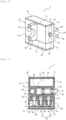
- Fig. 6 is a perspective view illustrating the front wheel-side hydraulic pressure control device according to the embodiment of the present invention.
- Fig. 6 is a perspective view in which the front wheel-side hydraulic pressure control device 1 is observed from the rear right side of the front wheel-side hydraulic pressure control device 1.
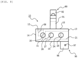
- Fig. 7 is a vertical cross-sectional view of the front wheel-side hydraulic pressure control device according to the embodiment of the present invention.
- Fig. 8 is a bottom view illustrating the base body of the front wheel-side hydraulic pressure control device according to the embodiment of the present invention.
- the front wheel-side hydraulic pressure control device 1 will be described below with reference to Figs. 6 to 8 and the above drawings.
- the base body 10 of the front wheel-side hydraulic pressure control device 1 is, for example, a substantially rectangular parallelepiped member made of an aluminum alloy. It should be noted that each surface of the base body 10 may be flat, may include a curved portion, or may include a step.
- the reservoir tank 52, an inlet valve mounting hole 24, an outlet valve mounting hole 26, the wheel cylinder port 45, and the piston mounting hole 21 of the master cylinder 50 are formed in the base body 10.
- the reservoir tank 52 is formed in the base body 10 so as to be open on a first surface 11.
- an opening portion 53 of the reservoir tank 52 is formed on the first surface 11.
- the front wheel-side hydraulic pressure control device 1 is mounted to the bicycle 200 such that the opening portion 53 of the reservoir tank 52 is the upper portion of the reservoir tank 52 so that the inside of the reservoir tank 52 is maintained at atmospheric pressure.
- the first surface 11 is the upper surface of the base body 10. It should be noted that the opening portion 53 of the reservoir tank 52 is covered with a lid 54.
- the inlet valve mounting hole 24 is a hole where the inlet valve 56 is provided so as to be capable of reciprocating.
- the inlet valve mounting hole 24 is formed in the base body 10 so as to be open on a second surface 12, which is opposite to the first surface 11. In other words, an opening portion 25 of the inlet valve mounting hole 24 is formed in the second surface 12.
- the second surface 12 is the lower surface of the base body 10.
- the inlet valve mounting hole 24 is formed in the base body 10 along, for example, the vertical direction.
- the first flow path 41 and the second flow path 42 of the internal flow path 40 illustrated in Fig. 3 communicate with the inlet valve mounting hole 24.
- the flow of the brake fluid between the first flow path 41 and the second flow path 42 is opened and closed by the inlet valve 56 reciprocating in the inlet valve mounting hole 24.
- the outlet valve mounting hole 26 is a hole where the outlet valve 57 is provided so as to be capable of reciprocating.
- the outlet valve mounting hole 26 is formed in the base body 10 so as to be open on the second surface 12. In other words, an opening portion 27 of the outlet valve mounting hole 26 is formed in the second surface 12.
- the outlet valve mounting hole 26 is formed in the base body 10 along, for example, the vertical direction.
- the third flow path 43 and the fourth flow path 44 of the internal flow path 40 illustrated in Fig. 3 communicate with the outlet valve mounting hole 26. The flow of the brake fluid between the third flow path 43 and the fourth flow path 44 is opened and closed by the outlet valve 57 reciprocating in the outlet valve mounting hole 26.
- the piston 51 of the master cylinder 50 is provided in the piston mounting hole 21 of the master cylinder 50 so as to be capable of reciprocating.
- the piston mounting hole 21 is formed in the base body 10 so as to be open on a third surface 13 connecting the first surface 11 and the second surface 12.
- an opening portion 23 of the piston mounting hole 21 is formed in the third surface 13.
- the third surface 13 is a side surface of the base body 10. More specifically, in the case of the front wheel-side hydraulic pressure control device 1 provided around the grip portion 234 on the right side of the handlebar 233, the third surface 13 is the right side surface of the base body 10. In addition, in the case of the rear wheel-side hydraulic pressure control device 2 provided around the grip portion 234 on the left side of the handlebar 233, the third surface 13 is the left side surface of the base body 10.
- the master cylinder 50 extends along the range of the handlebar 233 facing the master cylinder 50 in a plan view.
- the master cylinder 50 is formed on the base body 10 so as to extend substantially in the left-right direction.
- the wheel cylinder port 45 is formed in the base body 10 so as to be open on a fourth surface 14, which is opposite to the third surface 13.
- the inlet valve 56 In a state where the inlet valve 56 is provided in the inlet valve mounting hole 24, a part of the inlet valve 56 protrudes from the opening portion 25 of the inlet valve mounting hole 24 to the outside of the inlet valve mounting hole 24. In other words, in a state where the inlet valve 56 is provided in the inlet valve mounting hole 24, a part of the inlet valve 56 protrudes downward from the second surface 12 of the base body 10.
- the first coil 61 which is the drive source for the inlet valve 56, is provided so as to surround the part of the inlet valve 56 that protrudes downward beyond the base body 10.
- the first coil 61 is electrically connected to the control board 71 via a terminal 63.
- the outlet valve 57 In a state where the outlet valve 57 is provided in the outlet valve mounting hole 26, a part of the outlet valve 57 protrudes from the opening portion 27 of the outlet valve mounting hole 26 to the outside of the outlet valve mounting hole 26. In other words, in a state where the outlet valve 57 is provided in the outlet valve mounting hole 26, a part of the outlet valve 57 protrudes downward from the second surface 12 of the base body 10.
- the second coil 62 which is the drive source for the outlet valve 57, is provided so as to surround the part of the outlet valve 57 that protrudes downward beyond the base body 10.
- the second coil 62 is electrically connected to the control board 71 via a terminal 64.
- the first coil 61, the second coil 62, and the control board 71 are stored in a housing 80 included in the front wheel-side hydraulic pressure control device 1.
- the housing 80 is connected to the base body 10.
- the housing 80 storing the first coil 61, the second coil 62, and the control board 71 disposed below the base body 10 is also disposed below the base body 10.
- the inlet valve mounting hole and the outlet valve mounting hole are formed in the base body so as to extend in a substantially horizontal direction with the hydraulic pressure control device mounted to the handlebar.
- the inlet valve mounting hole and the outlet valve mounting hole are open to the front, rear, or side of the straddle-type vehicle when the hydraulic pressure control device is mounted to the handlebar.
- the housing storing the coil as the inlet valve drive source, the coil as the outlet valve drive source, and the control board controlling the energization of the coils is disposed so as to face the surface of the base body where the inlet valve mounting hole and the outlet valve mounting hole are open.
- the hydraulic pressure control device of the related art provided with the master cylinder-integrated base body it is imperative to ensure a housing disposition space in front of, behind, or beside the hydraulic pressure control device in mounting the hydraulic pressure control device on the handlebar.
- the straddle-type vehicle is provided with the handlebar behind the mounting position of the hydraulic pressure control device.
- various objects are also provided in front of and beside the mounting position of the hydraulic pressure control device. Accordingly, the hydraulic pressure control device of the related art provided with the master cylinder-integrated base body has a low degree of freedom of mounting on a straddle-type vehicle.
- the inlet valve mounting hole 24 and the outlet valve mounting hole 26 are formed on the second surface 12, which is the lower surface when the front wheel-side hydraulic pressure control device 1 is mounted to the handlebar 233 of the bicycle 200. Accordingly, when the front wheel-side hydraulic pressure control device 1 according to the present embodiment is mounted to the handlebar 233 of the bicycle 200, the first coil 61, the second coil 62, the control board 71, and the housing 80 are disposed below the base body 10.
- the direction of arrangement of the opening portion 25 of the inlet valve mounting hole 24 and the opening portion 27 of the outlet valve mounting hole 26 on the second surface 12 is along the direction of extension of the piston mounting hole 21 (direction in which the piston mounting hole 21 extends).
- the direction of arrangement of the opening portion 25 of the inlet valve mounting hole 24 and the opening portion 27 of the outlet valve mounting hole 26 on the second surface 12 is along the direction of extension of the piston mounting hole 21 (direction in which the piston mounting hole 21 extends).
- “along" expressed in the present embodiment does not mean that two compared directions are exactly parallel. The two compared directions may be slightly tilted. For example, the inclination of the two directions may be less than 45°.
- a hydraulic pressure control device provided with a master cylinder-integrated base body becomes large in the direction of extension of a piston mounting hole.
- the spatial margin in the front-rear direction is the least of those in the front-rear, left-right, and vertical directions.
- a hydraulic pressure control device provided with a master cylinder-integrated base body is mounted to the handlebar of a straddle-type vehicle such that the direction of extension of a piston mounting hole is along the left-right direction of the straddle-type vehicle in a plan view.
- a hydraulic pressure control device provided with a master cylinder-integrated base body is mounted to the handlebar of a straddle-type vehicle such that the direction of extension of a piston mounting hole is along the handlebar in a plan view.
- Fig. 2 the same applies to the front wheel-side hydraulic pressure control device 1 according to the present embodiment.
- the front wheel-side hydraulic pressure control device 1 having a configuration in which the direction of arrangement of the opening portion 25 of the inlet valve mounting hole 24 and the opening portion 27 of the outlet valve mounting hole 26 on the second surface 12 is along the direction of extension of the piston mounting hole 21 is capable of suppressing the width in the front-rear direction, in which the spatial margin is the least at the mounting position of the front wheel-side hydraulic pressure control device 1 of the bicycle 200. Accordingly, the degree of freedom of mounting on the bicycle 200 is further improved with the front wheel-side hydraulic pressure control device 1 having the configuration, that is, the rear wheel-side hydraulic pressure control device 2 having the configuration.
- the front wheel-side hydraulic pressure control device 1 includes the pressure sensor 59.
- the pressure sensor 59 is provided in a pressure sensor mounting hole 30 formed in the base body 10.
- the pressure sensor mounting hole 30 is formed in the base body 10 so as to be open on the second surface 12. In other words, an opening portion 31 of the pressure sensor mounting hole 30 is formed in the second surface 12.
- the pressure sensor mounting hole 30 is formed in the base body 10 along, for example, the vertical direction.
- the pressure sensor 59 and the control board 71 can be connected in the front-rear direction by the opening portion 31 of the pressure sensor mounting hole 30 being formed in the second surface 12.
- the front wheel-side hydraulic pressure control device 1 becoming large in the front-rear direction and the left-right direction can be suppressed even in a case where the pressure sensor 59 is provided in the base body 10. Accordingly, as for the front wheel-side hydraulic pressure control device 1 in which the opening portion 31 of the pressure sensor mounting hole 30 is formed in the second surface 12, that is, the rear wheel-side hydraulic pressure control device 2 in which the opening portion 31 of the pressure sensor mounting hole 30 is formed in the second surface 12, the degree of freedom of mounting on the bicycle 200 is improved as compared with the related art even in a case where the pressure sensor 59 is provided in the base body 10.
- the direction of arrangement of the opening portion 25 of the inlet valve mounting hole 24, the opening portion 27 of the outlet valve mounting hole 26, and the opening portion 31 of the pressure sensor mounting hole 30 on the second surface 12 is along the direction of extension of the piston mounting hole 21 (direction in which the piston mounting hole 21 extends).
- the direction of arrangement of the opening portion 25 of the inlet valve mounting hole 24, the opening portion 27 of the outlet valve mounting hole 26, and the opening portion 31 of the pressure sensor mounting hole 30 on the second surface 12 is along the direction of extension of the piston mounting hole 21 (direction in which the piston mounting hole 21 extends).
- the front wheel-side hydraulic pressure control device 1 configured as described above is capable of suppressing the width in the front-rear direction, in which the spatial margin is the least at the mounting position of the front wheel-side hydraulic pressure control device 1 of the bicycle 200, when the base body 10 is provided with the pressure sensor 59. Accordingly, with the front wheel-side hydraulic pressure control device 1 configured as described above, that is, the rear wheel-side hydraulic pressure control device 2 configured as described above, the degree of freedom of mounting on the bicycle 200 is further improved when the base body 10 is provided with the pressure sensor 59.
- opening portion 25 of the inlet valve mounting hole 24, the opening portion 27 of the outlet valve mounting hole 26, and the opening portion 31 of the pressure sensor mounting hole 30 on the second surface 12 do not necessarily have to be arranged in a straight line and may be arranged in a zigzag pattern.
- the pressure sensor mounting hole 30, the outlet valve mounting hole 26, and the inlet valve mounting hole 24 are arranged in order of being away from the wheel cylinder port 45.
- the pressure sensor 59 detects the pressure of the brake fluid applying pressure to the wheel cylinder 253.
- the inlet valve mounting hole 24, the outlet valve mounting hole 26, the pressure sensor mounting hole 30, and the wheel cylinder port 45 are arranged along the direction of flow of the brake fluid flowing through the internal flow path 40 from the piston mounting hole 21 of the master cylinder 50 toward the wheel cylinder port 45.
- the internal flow path 40 from the inlet valve mounting hole 24 to the wheel cylinder port 45 can be given a simple shape and the manufacturing cost can be suppressed.
- the holding portion 95 in the present embodiment includes a pair of holding plates 96. Holes 97 rotatably supporting a shaft portion 242 (see Fig. 2 ) of the brake lever 241 are formed in the holding plates 96. With the shaft portion 242 of the brake lever 241 inserted in the hole 97, the pair of holding plates 96 movably sandwich the brake lever 241. As a result, the brake lever 241 is swingably held by the holding portion 95.
- one of the pair of holding plates 96 is formed integrally with the base body 10 on, for example, a fifth surface 15, which is the front surface of the base body 10. It should be noted that the other of the pair of holding plates 96 is fixed to the base body 10 by, for example, screwing.
- the mounting portion 90 in the present embodiment includes a base portion 91 integrally formed on the base body 10 and a sandwiching portion 92 fixed to the base portion 91 by screwing or the like.
- the base portion 91 is formed integrally with the base body 10 on, for example, a sixth surface 16, which is the back surface of the base body 10.
- the base body 10 is fixed to the handlebar 233 by the handlebar 233 being sandwiched between the base portion 91 and the sandwiching portion 92 and the sandwiching portion 92 being fixed to the base portion 91.
- the mounting portion 90 By at least a part of the mounting portion 90 being integrally formed on the base body 10, the number of components and assembly man-hours of the bicycle 200 equipped with the brake system 100 and so on can be reduced and the manufacturing cost of the bicycle 200 can be suppressed as compared with a case where the mounting portion 90 is formed separately from the base body 10.
- the accumulator 58 is formed in the base body 10 of the front wheel-side hydraulic pressure control device 1. At this time, the accumulator 58 is disposed on the side opposite to the opening portion 23 of the piston mounting hole 21 with reference to a bottom portion 22 of the piston mounting hole 21. In other words, the piston mounting hole 21 of the master cylinder 50 and the accumulator 58 are arranged in the left-right direction in a plan view.
- the front wheel-side hydraulic pressure control device 1 in which the accumulator 58 is formed in this manner is capable of suppressing the width in the front-rear direction, in which the spatial margin is the least at the mounting position of the front wheel-side hydraulic pressure control device 1 of the bicycle 200.
- the degree of freedom of mounting on the bicycle 200 is improved when the accumulator 58 is formed in the base body 10.
- the accumulator 58 in the present embodiment is obtained by the opening portion of a hole open in the sixth surface 16 being blocked.
- this configuration of the accumulator 58 is merely an example.
- the accumulator 58 may be formed by the opening portion of a hole open in the fourth surface 14 being blocked.
- the accumulator 58 may be formed by the opening portion of a hole open in the fifth surface 15 being blocked.
- the hydraulic pressure control device (front wheel-side hydraulic pressure control device 1 and rear wheel-side hydraulic pressure control device 2) according to the present embodiment is used in the brake system 100 capable of executing anti-lock brake control and is mounted to the handlebar 233 of the bicycle 200.
- the hydraulic pressure control device according to the present embodiment has a configuration in which the accumulator 58 stores the brake fluid released from the wheel cylinder 253 during the pressure decrease in the anti-lock brake control and the brake fluid in the accumulator 58 is pumplessly discharged to the outside of the accumulator 58.
- the hydraulic pressure control device according to the present embodiment includes the base body 10, the inlet valve 56, and the outlet valve 57.
- the base body 10 has the piston mounting hole 21 where the piston 51 of the master cylinder 50 is provided so as to be capable of reciprocating, the reservoir tank 52 connected to the piston mounting hole 21 and storing the brake fluid, and the internal flow path 40 as a part of the brake fluid flow path that allows the piston mounting hole 21 and the wheel cylinder 253 to communicate with each other.
- the inlet valve 56 is provided in the inlet valve mounting hole 24 formed in the base body 10 so as to be capable of reciprocating and opens and closes the part of the internal flow path 40 through which the brake fluid flowing from the piston mounting hole 21 to the wheel cylinder 253 passes.
- the outlet valve 57 is provided in the outlet valve mounting hole 26 formed in the base body 10 so as to be capable of reciprocating and opens and closes the part of the internal flow path 40 through which the brake fluid flowing from the wheel cylinder 253 to the accumulator 58 passes.
- the surface of the base body 10 where the opening portion 53 of the reservoir tank 52 is formed is the first surface 11 and the surface of the base body 10 opposite to the first surface 11 is the second surface 12, the inlet valve mounting hole 24 and the outlet valve mounting hole 26 are open on the second surface 12.
- the first coil 61, the second coil 62, the control board 71, and the housing 80 are disposed below the base body 10 when the hydraulic pressure control device according to the present embodiment configured as described above is mounted to the handlebar 233 of the bicycle 200 as described above. Accordingly, the degree of freedom of mounting on the bicycle 200 is improved as compared with the related art with the hydraulic pressure control device according to the present embodiment configured as described above.
- Fig. 9 is a diagram illustrating a schematic configuration of a modification example of the brake system according to the embodiment of the present invention.
- the front wheel-side hydraulic pressure control device 1 and the rear wheel-side hydraulic pressure control device 2 have the configuration in which the accumulator 58 stores the brake fluid released from the wheel cylinder 253 during the pressure decrease in the anti-lock brake control and the brake fluid in the accumulator 58 is pumplessly discharged to the outside of the accumulator 58.
- the internal flow path 40 of the front wheel-side hydraulic pressure control device 1 and the rear wheel-side hydraulic pressure control device 2 realizing such a configuration is not limited to the configuration described above.
- the internal flow path 40 of the front wheel-side hydraulic pressure control device 1 and the rear wheel-side hydraulic pressure control device 2 may be configured as illustrated in Fig. 9 .
- the internal flow path 40 of the front wheel-side hydraulic pressure control device 1 and the rear wheel-side hydraulic pressure control device 2 illustrated in Fig. 9 includes a bypass flow path 46 and a check valve 47 in addition to the configuration of the internal flow path 40 illustrated in Fig. 2 .
- One end of the bypass flow path 46 is connected to the accumulator 58, and the other end of the bypass flow path 46 is connected to the first flow path 41.
- the check valve 47 is provided on the bypass flow path 46 and regulates the brake fluid flow from the master cylinder 50 side to the accumulator 58 side.
- the accumulator 58 is capable of storing the brake fluid released from the wheel cylinder 253 during the pressure decrease in the anti-lock brake control and the brake fluid in the accumulator 58 can be pumplessly discharged to the outside of the accumulator 58 via the bypass flow path 46.
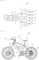
- Fig. 10 is a block diagram illustrating the modification example of the brake system according to the embodiment of the present invention.
- Fig. 11 is a side view illustrating a schematic configuration of a bicycle equipped with the modification example of the brake system according to the embodiment of the present invention.
- the component of the operation determination unit 73 is configured as an operation determination control board 72 different from the control board 71. Accordingly, in the front wheel-side hydraulic pressure control device 1 of the brake system 100 illustrated in Fig. 10 , the component of the control unit 74 is configured as the control board 71. Likewise, in the rear wheel-side hydraulic pressure control device 2 of the brake system 100 illustrated in Fig. 10 , the component of the operation determination unit 73 is configured as the operation determination control board 72 different from the control board 71. Accordingly, in the rear wheel-side hydraulic pressure control device 2 of the brake system 100 illustrated in Fig. 10 , the component of the control unit 74 is configured as the control board 71.
- the operation determination control board 72 of the front wheel-side hydraulic pressure control device 1 and the operation determination control board 72 of the rear wheel-side hydraulic pressure control device 2 are configurations used together.
- the operation determination control board 72 is stored at a part different from the housing 80 of the front wheel-side hydraulic pressure control device 1 and the housing 80 of the rear wheel-side hydraulic pressure control device 2.
- the signal output unit 75 of the front wheel-side hydraulic pressure control device 1 and the rear wheel-side hydraulic pressure control device 2 is also configured as the operation determination control board 72.
- the operation determination control board 72 determines the opening and closing operation of the control valve 55 of the front wheel-side hydraulic pressure control device 1 and determines the opening and closing operation of the control valve 55 of the rear wheel-side hydraulic pressure control device 2 based on information on the traveling state of the bicycle 200.
- the control board 71 of the front wheel-side hydraulic pressure control device 1 controls the opening and closing operation of the control valve 55 of the front wheel-side hydraulic pressure control device 1 based on the determination by the operation determination control board 72.
- the control board 71 of the front wheel-side hydraulic pressure control device 1 controls the energization of the first coil 61 and the second coil 62 of the front wheel-side hydraulic pressure control device 1 based on the determination by the operation determination control board 72.
- control board 71 of the rear wheel-side hydraulic pressure control device 2 controls the opening and closing operation of the control valve 55 of the rear wheel-side hydraulic pressure control device 2 based on the determination by the operation determination control board 72.
- control board 71 of the rear wheel-side hydraulic pressure control device 2 controls the energization of the first coil 61 and the second coil 62 of the rear wheel-side hydraulic pressure control device 2 based on the determination by the operation determination control board 72.
- the operation determination control board 72 can be stored in a housing different from the housing 80 of the front wheel-side hydraulic pressure control device 1 and the housing 80 of the rear wheel-side hydraulic pressure control device 2.
- the front wheel-side hydraulic pressure control device 1 and the rear wheel-side hydraulic pressure control device 2 can be further reduced in size with the brake system 100 configured as described above and the degree of freedom of mounting of the front wheel-side hydraulic pressure control device 1 and the rear wheel-side hydraulic pressure control device 2 on the bicycle 200 is further improved.
- the number of signal lines connected to the front wheel-side hydraulic pressure control device 1 and the rear wheel-side hydraulic pressure control device 2 can be reduced and an increase in complexity around the handlebar 233 can be further suppressed.
- the operation determination control board 72 is preferably mounted to the bicycle 200 at a position behind the handlebar 233. As a result, a stone or the like hitting the housing for storing the operation determination control board 72 during the traveling of the bicycle 200 can be suppressed and the reliability of the brake system 100 is improved.
- the operation determination control board 72 is preferably formed integrally with the other device control board 280.
- the bicycle 200 illustrated in Fig. 11 includes a control board monitoring the charge amount of the power source unit 260.
- the control board monitoring the charge amount of the power source unit 260 is used as the other device control board 280.
- the other device control board 280 is not particularly limited insofar as it is a control board of a device other than the brake system 100.
- some straddle-type vehicles provided with an engine as a drive source are provided with an engine control unit.
- the control board of the engine control unit may be used as the other device control board 280.
- the manufacturing cost of the brake system 100 can be reduced as compared with a case where the operation determination control board 72 is manufactured as a dedicated control board.
- a detection device such as the pressure sensor 59
- the number of signal lines routed to the bicycle 200 can be reduced and the manufacturing man-hours and manufacturing cost of the bicycle 200 can be reduced as compared with a case where the operation determination control board 72 is manufactured as a dedicated control board.
Landscapes
- Engineering & Computer Science (AREA)
- Mechanical Engineering (AREA)
- Transportation (AREA)
- Physics & Mathematics (AREA)
- Fluid Mechanics (AREA)
- Regulating Braking Force (AREA)
- Hydraulic Control Valves For Brake Systems (AREA)
Abstract
To obtain a hydraulic pressure control device with which the degree of freedom of mounting on a straddle-type vehicle can be improved as compared with the related art.
The hydraulic pressure control device according to the present invention is used in a brake system capable of executing anti-lock brake control and mounted to a handlebar of a straddle-type vehicle. The hydraulic pressure control device includes: a master cylinder-integrated base body where a reservoir tank for brake fluid storage connected to a master cylinder and an internal flow path through which a brake fluid flows are formed; and inlet and outlet valves provided in the base body and opening and closing the internal flow path. An inlet valve mounting hole storing the inlet valve and an outlet valve mounting hole storing the outlet valve are open on a second surface in a case where a surface of the base body where an opening portion of the reservoir tank is formed is a first surface and a surface of the base body opposite to the first surface is the second surface.
Description
- The present invention relates to a hydraulic pressure control device used in a brake system equipped in a straddle-type vehicle and a straddle-type vehicle provided with the hydraulic pressure control device.
- In the related art, a straddle-type vehicle is provided with a brake system capable of executing anti-lock brake control, which is to control the braking force of a vehicle wheel by controlling the hydraulic pressure of a brake fluid. The brake system includes a hydraulic pressure control device. In addition, a hydraulic pressure control device in which a base body having an internal flow path through which a brake fluid flows and a master cylinder are integrated with each other has been proposed as a hydraulic pressure control device of the related art used in a brake system capable of executing anti-lock brake control (see PTL 1).
- Specifically, the internal flow path as a part of a brake flow path allowing the master cylinder and a wheel cylinder to communicate with each other is formed in the master cylinder-integrated base body. Also formed in the master cylinder-integrated base body are a piston mounting hole where the piston of the master cylinder is provided so as to be capable of reciprocating, a reservoir tank for brake fluid storage connected to the piston mounting hole, an inlet valve mounting hole where an inlet valve is provided, and an outlet valve mounting hole where an outlet valve is provided. It should be noted that the inlet valve opens and closes the part of the internal flow path through which the brake fluid flowing from the piston mounting hole to the wheel cylinder passes. In addition, the outlet valve opens and closes the part of the internal flow path through which the brake fluid flowing from the wheel cylinder to an accumulator (part storing the brake fluid released from the wheel cylinder during pressure decrease in anti-lock brake control) passes.
- In the hydraulic pressure control device provided with the master cylinder-integrated base body, the piston of the master cylinder is pressed by a rider gripping a brake lever with his or her hand. Accordingly, the hydraulic pressure control device provided with the master cylinder-integrated base body is mounted to the handlebar of a straddle-type vehicle.
- PTL 1:
JP-B-4783391 - In the hydraulic pressure control device of the related art provided with the master cylinder-integrated base body, the inlet valve mounting hole and the outlet valve mounting hole are formed in the base body so as to extend in a substantially horizontal direction with the hydraulic pressure control device mounted to the handlebar. In other words, in the hydraulic pressure control device of the related art provided with the master cylinder-integrated base body, the inlet valve mounting hole and the outlet valve mounting hole are open to the front, rear, or side of the straddle-type vehicle when the hydraulic pressure control device is mounted to the handlebar.
- Here, in the hydraulic pressure control device provided with the master cylinder-integrated base body, a housing storing a coil as an inlet valve drive source, a coil as an outlet valve drive source, and a control board controlling the energization of the coils is disposed so as to face the surface of the base body where the inlet valve mounting hole and the outlet valve mounting hole are open. In other words, as for the hydraulic pressure control device of the related art provided with the master cylinder-integrated base body, it is imperative to ensure a housing disposition space in front of, behind, or beside the hydraulic pressure control device in mounting the hydraulic pressure control device on the handlebar. However, as for the straddle-type vehicle, various objects are provided in front of, behind, and beside the mounting position of the hydraulic pressure control device. Accordingly, the hydraulic pressure control device of the related art provided with the master cylinder-integrated base body is problematic in that the degree of freedom of mounting on a straddle-type vehicle is low.
- The present invention has been made in view of the above, and an object of the present invention is to obtain a hydraulic pressure control device with which the degree of freedom of mounting on a straddle-type vehicle can be improved as compared with the related art. Another object of the present invention is to obtain a straddle-type vehicle provided with such a hydraulic pressure control device.
- A hydraulic pressure control device according to the present invention is used in a brake system capable of executing anti-lock brake control and mounted to a handlebar of a straddle-type vehicle. The hydraulic pressure control device has a configuration in which a brake fluid released from a wheel cylinder during pressure decrease in the anti-lock brake control is stored in an accumulator and the brake fluid in the accumulator is pumplessly discharged out of the accumulator and includes: a master cylinder-integrated base body where a piston mounting hole where a piston of a master cylinder is provided so as to be capable of reciprocating, a reservoir tank for brake fluid storage connected to the piston mounting hole, and an internal flow path as a part of a brake fluid flow path allowing the piston mounting hole and the wheel cylinder to communicate with each other are formed; an inlet valve provided in an inlet valve mounting hole formed in the base body so as to be capable of reciprocating and opening and closing a part of the internal flow path through which a brake fluid flowing from the piston mounting hole to the wheel cylinder passes; and an outlet valve provided in an outlet valve mounting hole formed in the base body so as to be capable of reciprocating and opening and closing a part of the internal flow path through which a brake fluid flowing from the wheel cylinder to the accumulator passes, in which the inlet valve mounting hole and the outlet valve mounting hole are open on a second surface in a case where a surface of the base body where an opening portion of the reservoir tank is formed is a first surface and a surface of the base body opposite to the first surface is the second surface.
- In addition, a straddle-type vehicle according to the present invention includes the hydraulic pressure control device according to the present invention.
- In the base body of the hydraulic pressure control device according to the present invention, the inlet valve mounting hole and the outlet valve mounting hole are open on the second surface opposite to the opening portion of the reservoir tank. When the hydraulic pressure control device is mounted to the handlebar of the straddle-type vehicle, the surface of the base body where the opening portion of the reservoir tank is formed (first surface) faces upward. In other words, when the hydraulic pressure control device according to the present invention is mounted to the handlebar of the straddle-type vehicle, the second surface of the base body faces downward. Accordingly, when the hydraulic pressure control device according to the present invention is mounted to the handlebar of the straddle-type vehicle, a coil, a control board, and a housing are disposed below the base body. Here, in the straddle-type vehicle, there is a spatial margin in the vertical direction around the mounting position of the hydraulic pressure control device as compared with the front, rear, and side where various objects are provided. Accordingly, the degree of freedom of mounting on the straddle-type vehicle is improved as compared with the related art with the hydraulic pressure control device according to the present invention.
-
-
Fig. 1 is a side view illustrating a schematic configuration of a bicycle equipped with a brake system according to an embodiment of the present invention. -
Fig. 2 is a plan view illustrating the periphery of a handlebar of the bicycle equipped with the brake system according to the embodiment of the present invention. -
Fig. 3 is a diagram illustrating a schematic configuration of the brake system according to the embodiment of the present invention. -
Fig. 4 is a block diagram illustrating a front wheel-side hydraulic pressure control device according to the embodiment of the present invention. -
Fig. 5 is a block diagram illustrating a rear wheel-side hydraulic pressure control device according to the embodiment of the present invention. -
Fig. 6 is a perspective view illustrating the front wheel-side hydraulic pressure control device according to the embodiment of the present invention. -
Fig. 7 is a vertical cross-sectional view of the front wheel-side hydraulic pressure control device according to the embodiment of the present invention. -
Fig. 8 is a bottom view illustrating a base body of the front wheel-side hydraulic pressure control device according to the embodiment of the present invention. -
Fig. 9 is a diagram illustrating a schematic configuration of a modification example of the brake system according to the embodiment of the present invention. -
Fig. 10 is a block diagram illustrating the modification example of the brake system according to the embodiment of the present invention. -
Fig. 11 is a side view illustrating a schematic configuration of a bicycle equipped with the modification example of the brake system according to the embodiment of the present invention. - Hereinafter, a hydraulic pressure control device according to the present invention, a brake system provided with the hydraulic pressure control device, and a straddle-type vehicle provided with the hydraulic pressure control device will be described with reference to the drawings.
- It should be noted that a case where the present invention is adopted for a bicycle (such as two-wheeled and three-wheeled vehicles) will be described below. Alternatively, the present invention may be adopted for a straddle-type vehicle other than a bicycle. The straddle-type vehicle means every vehicle ridden by a straddling rider. Examples of the straddle-type vehicle other than a bicycle include an automatic two-wheeled vehicle, an automatic three-wheeled vehicle, and a buggy using at least one of an engine and an electric motor as a drive source. In addition, the bicycle means every vehicle that can be propelled on the road by pedal effort. In other words, the bicycle includes ordinary, electrically assisted, and electric bicycles. In addition, the automatic two-wheeled or three-wheeled vehicle means a so-called motorcycle and the motorcycle includes an autobike, a scooter, and an electric scooter.
- In addition, the following configuration, operation, and so on are examples and the hydraulic pressure control device, the brake system, and the straddle-type vehicle according to the present invention are not limited thereto. For example, in the following description, the brake system according to the present invention includes front wheel-side and rear wheel-side hydraulic pressure control devices for executing anti-lock brake control on front and rear wheels, respectively. However, the brake system according to the present invention may include only one of the front wheel-side hydraulic pressure control device and the rear wheel-side hydraulic pressure control device. In addition, the brake system according to the present invention may, for example, execute anti-lock brake control on both the front and rear wheels using one hydraulic pressure control device.
- In addition, in the drawings, the same or similar members or parts are denoted by the same reference numerals or lack reference numerals. In addition, the illustration is simplified or omitted as appropriate regarding a detailed structure. In addition, redundant description is simplified or omitted as appropriate.
- Equipping a bicycle with a brake system according to an embodiment will be described.
-
Fig. 1 is a side view illustrating a schematic configuration of the bicycle equipped with the brake system according to the embodiment of the present invention.Fig. 2 is a plan view illustrating the periphery of a handlebar of the bicycle equipped with the brake system according to the embodiment of the present invention. It should be noted that the left side of the page is the front of abicycle 200 inFig. 1 . In addition, inFig. 2 , the upper side of the page is the front of thebicycle 200. In addition,Fig. 2 illustrates a state where brake levers 241 are not gripped by a rider. In addition, inFig. 2 , a front wheel-side hydraulicpressure control device 1 and a rear wheel-side hydraulicpressure control device 2 are illustrated in cross section in part. - The
bicycle 200 equipped with abrake system 100 includes aframe 210, a turningportion 230, asaddle 218, apedal 219, arear wheel 220, a rear wheel-side braking portion 252, and abrake lamp 221. - The
frame 210 includes, for example, ahead tube 211 axially supporting asteering column 231 of the turningportion 230, atop tube 212 and adown tube 213 connected to thehead tube 211, aseat tube 214 connected to thetop tube 212 and thedown tube 213 and holding thesaddle 218, and astay 215 connected to the upper and lower ends of theseat tube 214 and holding therear wheel 220 and the rear wheel-side braking portion 252. - The turning
portion 230 includes, for example, thesteering column 231, ahandle stem 232 held by thesteering column 231, ahandlebar 233 held by thehandle stem 232, the brake levers 241 provided around thehandlebar 233,front forks 216 connected to thesteering column 231, afront wheel 217 rotatably held by thefront forks 216, and a front wheel-side braking portion 251. Thefront forks 216 are provided on both sides of thefront wheel 217. One end of thefront forks 216 is connected to thesteering column 231, and the other end of thefront forks 216 is connected to the center of rotation of thefront wheel 217. In other words, thefront wheel 217 is rotatably held between the pair offront forks 216. It should be noted that thefront fork 216 may be a front fork equipped with a suspension system. - The
bicycle 200 according to the present embodiment includes the two brake levers 241. Specifically, as illustrated inFig. 2 , thebrake system 100 includes the front wheel-side hydraulicpressure control device 1 for executing anti-lock brake control on thefront wheel 217 and the rear wheel-side hydraulicpressure control device 2 for executing anti-lock brake control on therear wheel 220. The front wheel-side hydraulicpressure control device 1 and the rear wheel-side hydraulicpressure control device 2 include master cylinder-integratedbase bodies 10 as will be described later. A hydraulic pressure control device provided with a master cylinder-integrated base body is mounted to a handlebar and has a configuration in which the piston of the master cylinder is pressed by a brake lever hand-gripped by a rider. Accordingly, the front wheel-side hydraulicpressure control device 1 and the rear wheel-side hydraulicpressure control device 2 are mounted to thehandlebar 233. Thebicycle 200 includes thebrake lever 241 for the front wheel-side hydraulicpressure control device 1 and thebrake lever 241 for the rear wheel-side hydraulicpressure control device 2. - In a case where both the front wheel-side hydraulic
pressure control device 1 and the rear wheel-side hydraulicpressure control device 2 are mounted to thehandlebar 233, one of the front wheel-side hydraulicpressure control device 1 and the rear wheel-side hydraulicpressure control device 2 is provided around one grip portion 234 (grip portion 234 on the left side), which the rider grips with his or her left hand, of thehandlebar 233. In addition, the other of the front wheel-side hydraulicpressure control device 1 and the rear wheel-side hydraulicpressure control device 2 is provided around the other grip portion 234 (grip portion 234 on the right side), which the rider grips with his or her right hand, of thehandlebar 233. Accordingly, when thebicycle 200 is equipped with thebrake system 100 according to the present embodiment, the weight distribution of the attachment to thehandlebar 233 in the left-right direction becomes more even than in the related art and the steerability of thebicycle 200 is improved as compared with the related art. It should be noted thatFig. 2 illustrates an example in which the rear wheel-side hydraulicpressure control device 2 is provided around thegrip portion 234 that the rider grips with his or her left hand and the front wheel-side hydraulicpressure control device 1 is provided around thegrip portion 234 that the rider grips with his or her right hand. - A
power source unit 260 as a power source for the front wheel-side hydraulicpressure control device 1 and the rear wheel-side hydraulicpressure control device 2 is mounted to, for example, thedown tube 213 of theframe 210. Thepower source unit 260 may be a battery or a generator. Examples of the generator include a generator generating electricity by thebicycle 200 traveling (such as a hub dynamo generating electricity by thefront wheel 217 or therear wheel 220 rotating and a generator performing regenerative power generation as an electric motor of a drive source for thefront wheel 217 or the rear wheel 220) and a generator generating electricity from sunlight. - In other words, the
bicycle 200 is equipped with thebrake system 100 including at least thebrake lever 241, the front wheel-side braking portion 251, the rear wheel-side braking portion 252, the front wheel-side hydraulicpressure control device 1, the rear wheel-side hydraulicpressure control device 2, and thepower source unit 260. Thebrake system 100 is capable of executing anti-lock brake control on thefront wheel 217 by controlling the pressure of the brake fluid of the front wheel-side braking portion 251 with the front wheel-side hydraulicpressure control device 1. In addition, thebrake system 100 is capable of executing anti-lock brake control on therear wheel 220 by controlling the pressure of the brake fluid of the rear wheel-side braking portion 252 with the rear wheel-side hydraulicpressure control device 2. - The
brake lamp 221 emits light when at least one of thefront wheel 217 and therear wheel 220 is braked. - The configuration of the brake system according to the embodiment will be described.
-
Fig. 3 is a diagram illustrating a schematic configuration of the brake system according to the embodiment of the present invention. - As described above, the
brake system 100 includes the front wheel-side hydraulicpressure control device 1 and the rear wheel-side hydraulicpressure control device 2. The front wheel-side hydraulicpressure control device 1 and the rear wheel-side hydraulicpressure control device 2 include the master cylinder-integratedbase bodies 10. Specifically, as will be described in detail later, thebase body 10 is formed with apiston mounting hole 21 where apiston 51 of amaster cylinder 50 is provided so as to be capable of reciprocating. Themaster cylinder 50 is configured by thepiston mounting hole 21 and thepiston 51. In addition, thebase body 10 is formed with awheel cylinder port 45 and aninternal flow path 40 allowing thepiston mounting hole 21 and thewheel cylinder port 45 to communicate with each other. In addition, thebase body 10 is formed with areservoir tank 52 for brake fluid storage connected to thepiston mounting hole 21. - The
internal flow path 40 is a brake fluid flow path. Theinternal flow path 40 includes, for example, afirst flow path 41, asecond flow path 42, athird flow path 43, and afourth flow path 44. Thepiston mounting hole 21 of themaster cylinder 50 and thewheel cylinder port 45 communicate with each other via thefirst flow path 41 and thesecond flow path 42. In addition, the inlet-side end portion of thethird flow path 43 is connected to the middle portion of thesecond flow path 42. - The front wheel-
side braking portion 251 is connected via aliquid pipe 101 to thewheel cylinder port 45 of thebase body 10 of the front wheel-side hydraulicpressure control device 1. The front wheel-side braking portion 251 includes awheel cylinder 253 and arotor 254. Thewheel cylinder 253 of the front wheel-side braking portion 251 is mounted to, for example, thefront fork 216. Thewheel cylinder 253 of the front wheel-side braking portion 251 includes a piston portion (not illustrated) moving in conjunction with the pressure of theliquid pipe 101 and is connected to the outlet side of thesecond flow path 42 of the front wheel-side hydraulicpressure control device 1 via theliquid pipe 101 and thewheel cylinder port 45. In other words, thewheel cylinder port 45 of thebase body 10 of the front wheel-side hydraulicpressure control device 1 is connected to theliquid pipe 101 communicating with thewheel cylinder 253 of the front wheel-side braking portion 251. Therotor 254 of the front wheel-side braking portion 251 is held by thefront wheel 217 and rotates together with thefront wheel 217. As a result of the movement of the piston portion of thewheel cylinder 253 of the front wheel-side braking portion 251, a brake pad (not illustrated) is pressed against therotor 254 of the front wheel-side braking portion 251 and thefront wheel 217 is braked. - The rear wheel-
side braking portion 252 is connected via theliquid pipe 101 to thewheel cylinder port 45 of thebase body 10 of the rear wheel-side hydraulicpressure control device 2. The rear wheel-side braking portion 252 includes thewheel cylinder 253 and therotor 254 as in the case of the front wheel-side braking portion 251. Thewheel cylinder 253 of the rear wheel-side braking portion 252 is mounted to, for example, thestay 215. Thewheel cylinder 253 of the rear wheel-side braking portion 252 includes a piston portion (not illustrated) moving in conjunction with the pressure of theliquid pipe 101 and is connected to the outlet side of thesecond flow path 42 of the rear wheel-side hydraulicpressure control device 2 via theliquid pipe 101 and thewheel cylinder port 45. In other words, thewheel cylinder port 45 of thebase body 10 of the rear wheel-side hydraulicpressure control device 2 is connected to theliquid pipe 101 communicating with thewheel cylinder 253 of the rear wheel-side braking portion 252. Therotor 254 of the rear wheel-side braking portion 252 is held by therear wheel 220 and rotates together with therear wheel 220. As a result of the movement of the piston portion of thewheel cylinder 253 of the rear wheel-side braking portion 252, a brake pad (not illustrated) is pressed against therotor 254 of the rear wheel-side braking portion 252 and therear wheel 220 is braked. - In other words, the
internal flow path 40 formed in thebase body 10 of the front wheel-side hydraulicpressure control device 1 and the rear wheel-side hydraulicpressure control device 2 is a part of the brake fluid flow path that allows thepiston mounting hole 21 and thewheel cylinder 253 to communicate with each other. - In addition, the front wheel-side hydraulic
pressure control device 1 and the rear wheel-side hydraulicpressure control device 2 are provided with acontrol valve 55 opening and closing theinternal flow path 40 and adjusting the pressure of the brake fluid supplied to thewheel cylinder 253. Thecontrol valve 55 is provided in thebase body 10. In the present embodiment, the front wheel-side hydraulicpressure control device 1 and the rear wheel-side hydraulicpressure control device 2 include aninlet valve 56 and anoutlet valve 57 as thecontrol valve 55. - The
inlet valve 56 is provided between the outlet side of thefirst flow path 41 and the inlet side of thesecond flow path 42 and opens and closes the brake fluid flow between thefirst flow path 41 and thesecond flow path 42. In other words, theinlet valve 56 opens and closes the part of theinternal flow path 40 through which the brake fluid flowing from thepiston mounting hole 21 to thewheel cylinder 253 passes. Theoutlet valve 57 is provided between the outlet side of thethird flow path 43 and the inlet side of thefourth flow path 44 and opens and closes the brake fluid flow between thethird flow path 43 and thefourth flow path 44. The pressure of the brake fluid is controlled by the opening and closing operation of theinlet valve 56 and theoutlet valve 57. - In addition, the front wheel-side hydraulic
pressure control device 1 and the rear wheel-side hydraulicpressure control device 2 include afirst coil 61 as a drive source for theinlet valve 56 and asecond coil 62 as a drive source for theoutlet valve 57. For example, when thefirst coil 61 is in a non-energized state, theinlet valve 56 opens the flow of the brake fluid in both directions. When thefirst coil 61 is energized, theinlet valve 56 is closed and shuts off the flow of the brake fluid. In other words, in the present embodiment, theinlet valve 56 is an electromagnetic valve that is open when not energized. In addition, theoutlet valve 57 shuts off the flow of the brake fluid when, for example, thesecond coil 62 is in a non-energized state. When thesecond coil 62 is energized, theoutlet valve 57 is opened and opens the flow of the brake fluid in both directions. In other words, in the present embodiment, theoutlet valve 57 is an electromagnetic valve that is closed when not energized. - In addition, an
accumulator 58 is formed in thebase body 10 of the front wheel-side hydraulicpressure control device 1 and the rear wheel-side hydraulicpressure control device 2. Theaccumulator 58 is connected to the outlet side of thefourth flow path 44 and stores the brake fluid that has passed through theoutlet valve 57. In other words, theoutlet valve 57 opens and closes the part of theinternal flow path 40 through which the brake fluid flowing from thewheel cylinder 253 to theaccumulator 58 passes. - In addition, the front wheel-side hydraulic
pressure control device 1 and the rear wheel-side hydraulicpressure control device 2 include apressure sensor 59 detecting the pressure of the brake fluid in theinternal flow path 40. Thepressure sensor 59 is provided in thebase body 10. In the present embodiment, thepressure sensor 59 detects the pressure of the brake fluid that applies pressure to thewheel cylinder 253. For example, thepressure sensor 59 communicates with thesecond flow path 42. - In addition, the front wheel-side hydraulic
pressure control device 1 and the rear wheel-side hydraulicpressure control device 2 include acontrol device 70 controlling the opening and closing operation of thecontrol valve 55 based on the detection result of thepressure sensor 59. It should be noted that each unit of thecontrol device 70 may be arranged together or dispersedly. In addition, at least a part of thecontrol device 70 of the front wheel-side hydraulicpressure control device 1 and at least a part of thecontrol device 70 of the rear wheel-side hydraulicpressure control device 2 may be arranged together. Thecontrol device 70 may be configured to include, for example, a microcomputer and a microprocessor unit, may be configured to include what is updatable such as firmware, or may be configured to include, for example, a program module executed by a command from a CPU or the like. For example, thecontrol device 70 of the front wheel-side hydraulicpressure control device 1 and the rear wheel-side hydraulicpressure control device 2 is configured as follows. -
Fig. 4 is a block diagram illustrating the front wheel-side hydraulic pressure control device according to the embodiment of the present invention. In addition,Fig. 5 is a block diagram illustrating the rear wheel-side hydraulic pressure control device according to the embodiment of the present invention. - The detection result of the
pressure sensor 59 is input to thecontrol device 70 of the front wheel-side hydraulicpressure control device 1 and the rear wheel-side hydraulicpressure control device 2. In addition, in the present embodiment, the detection result of a front wheel-side vehiclewheel speed sensor 271 detecting the rotation speed of thefront wheel 217 as a detection device detecting information on the traveling state of thebicycle 200 is input to thecontrol device 70 of the front wheel-side hydraulicpressure control device 1. Then, thecontrol device 70 of the front wheel-side hydraulicpressure control device 1 determines whether thefront wheel 217 is locked or the possibility of thefront wheel 217 being locked based on the detection result of the front wheel-side vehiclewheel speed sensor 271. In addition, in the present embodiment, the detection result of a rear wheel-side vehiclewheel speed sensor 272 detecting the rotation speed of therear wheel 220 as a detection device detecting information on the traveling state of thebicycle 200 is input to thecontrol device 70 of the rear wheel-side hydraulicpressure control device 2. Then, thecontrol device 70 of the rear wheel-side hydraulicpressure control device 2 determines whether therear wheel 220 is locked or the possibility of therear wheel 220 being locked based on the detection result of the rear wheel-side vehiclewheel speed sensor 272. - The
control device 70 includes anoperation determination unit 73 and acontrol unit 74 as functional units. Theoperation determination unit 73 is a functional unit determining the opening and closing operation of thecontrol valve 55. Specifically, theoperation determination unit 73 determines whether to open or close theinlet valve 56. In addition, theoperation determination unit 73 determines whether to open or close theoutlet valve 57. Thecontrol unit 74 is a functional unit controlling the opening and closing operation of thecontrol valve 55. Specifically, thecontrol unit 74 controls the energization of thefirst coil 61 to turn the state of theinlet valve 56 into the state determined by theoperation determination unit 73. In addition, thecontrol unit 74 controls the energization of thesecond coil 62 to turn the state of theoutlet valve 57 into the state determined by theoperation determination unit 73. - In other words, the
control device 70 of the front wheel-side hydraulicpressure control device 1 controls the pressure of the brake fluid supplied to thewheel cylinder 253 of the front wheel-side braking portion 251 and controls the braking force of thefront wheel 217 by controlling the opening and closing operation of theinlet valve 56 and theoutlet valve 57 of the front wheel-side hydraulicpressure control device 1. In other words, the front wheel-side hydraulicpressure control device 1 controls the pressure of the brake fluid supplied to thewheel cylinder 253 of the front wheel-side braking portion 251. In addition, thecontrol device 70 of the rear wheel-side hydraulicpressure control device 2 controls the pressure of the brake fluid supplied to thewheel cylinder 253 of the rear wheel-side braking portion 252 and controls the braking force of therear wheel 220 by controlling the opening and closing operation of theinlet valve 56 and theoutlet valve 57 of the rear wheel-side hydraulicpressure control device 2. In other words, the rear wheel-side hydraulicpressure control device 2 controls the pressure of the brake fluid supplied to thewheel cylinder 253 of the rear wheel-side braking portion 252. - For example, the
control device 70 of the front wheel-side hydraulicpressure control device 1 operates as follows. The braking of thefront wheel 217 is initiated when the rider grips thebrake lever 241 and thepiston 51 of themaster cylinder 50 of the front wheel-side hydraulicpressure control device 1 is pressed by thebrake lever 241. With thefront wheel 217 braked, thecontrol device 70 of the front wheel-side hydraulicpressure control device 1 initiates anti-lock brake control when it is determined based on the detection result of the front wheel-side vehiclewheel speed sensor 271 that thefront wheel 217 is or may be locked. - With the anti-lock brake control initiated, the
control device 70 of the front wheel-side hydraulicpressure control device 1 energizes thefirst coil 61, closes theinlet valve 56, and shuts off the brake fluid flow from themaster cylinder 50 to thewheel cylinder 253 of the front wheel-side braking portion 251. As a result, an increase in the pressure of the brake fluid of thewheel cylinder 253 of the front wheel-side braking portion 251 is suppressed. Meanwhile, thecontrol device 70 of the front wheel-side hydraulicpressure control device 1 energizes thesecond coil 62, opens theoutlet valve 57, and allows the brake fluid to flow from thewheel cylinder 253 of the front wheel-side braking portion 251 to theaccumulator 58. As a result, the pressure of the brake fluid of thewheel cylinder 253 of the front wheel-side braking portion 251 decreases. As a result, the lock of thefront wheel 217 is released or avoided. When it is determined from the detection result of thepressure sensor 59 that the pressure of the brake fluid of thewheel cylinder 253 of the front wheel-side braking portion 251 has decreased to a predetermined value, thecontrol device 70 of the front wheel-side hydraulicpressure control device 1 closes theoutlet valve 57 by de-energizing thesecond coil 62, opens theinlet valve 56 by de-energizing thefirst coil 61 for a short time, and increases the pressure of the brake fluid of thewheel cylinder 253 of the front wheel-side braking portion 251. Thecontrol device 70 of the front wheel-side hydraulicpressure control device 1 may increase or decrease the pressure of thewheel cylinder 253 of the front wheel-side braking portion 251 only once or may repeat the increase or decrease a plurality of times. - Here, as described above, the
pressure sensor 59 detects the pressure of the brake fluid that is in theinternal flow path 40 and applies pressure to thewheel cylinder 253. Accordingly, thepressure sensor 59 is capable of directly detecting the brake fluid of thewheel cylinder 253 of the front wheel-side braking portion 251. Accordingly, by thepressure sensor 59 detecting the pressure of the brake fluid applying pressure to thewheel cylinder 253, the front wheel-side hydraulicpressure control device 1 is capable of performing anti-lock brake control on thefront wheel 217 with high accuracy. - With the anti-lock brake control completed and the
brake lever 241 corresponding to the front wheel-side hydraulicpressure control device 1 returned, the inside of themaster cylinder 50 of the front wheel-side hydraulicpressure control device 1 reaches atmospheric pressure and the brake fluid in thewheel cylinder 253 of the front wheel-side braking portion 251 is returned. In addition, the front wheel-side hydraulicpressure control device 1 opens theoutlet valve 57 with the anti-lock brake control completed and thebrake lever 241 corresponding to the front wheel-side hydraulicpressure control device 1 returned. When the pressure of the brake fluid in theinternal flow path 40 becomes lower than the pressure of the brake fluid stored in theaccumulator 58 as a result, the brake fluid stored in theaccumulator 58 is discharged to the outside of theaccumulator 58 pumplessly (that is, without boosting). Then, the brake fluid discharged to the outside theaccumulator 58 returns to themaster cylinder 50 through thefourth flow path 44, theoutlet valve 57, thethird flow path 43, thesecond flow path 42, and thefirst flow path 41. In addition, the surplus brake fluid that has returned to themaster cylinder 50 is stored in thereservoir tank 52. - Likewise, for example, the
control device 70 of the rear wheel-side hydraulicpressure control device 2 operates as follows. The braking of therear wheel 220 is initiated when the rider grips thebrake lever 241 and thepiston 51 of themaster cylinder 50 of the rear wheel-side hydraulicpressure control device 2 is pressed by thebrake lever 241. With therear wheel 220 braked, thecontrol device 70 of the rear wheel-side hydraulicpressure control device 2 initiates anti-lock brake control when it is determined based on the detection result of the rear wheel-side vehiclewheel speed sensor 272 that therear wheel 220 is or may be locked. - With the anti-lock brake control initiated, the
control device 70 of the rear wheel-side hydraulicpressure control device 2 energizes thefirst coil 61, closes theinlet valve 56, and shuts off the brake fluid flow from themaster cylinder 50 to thewheel cylinder 253 of the rear wheel-side braking portion 252. As a result, an increase in the pressure of the brake fluid of thewheel cylinder 253 of the rear wheel-side braking portion 252 is suppressed. Meanwhile, thecontrol device 70 of the rear wheel-side hydraulicpressure control device 2 energizes thesecond coil 62, opens theoutlet valve 57, and allows the brake fluid to flow from thewheel cylinder 253 of the rear wheel-side braking portion 252 to theaccumulator 58. As a result, the pressure of the brake fluid of thewheel cylinder 253 of the rear wheel-side braking portion 252 decreases. As a result, the lock of therear wheel 220 is released or avoided. When it is determined from the detection result of thepressure sensor 59 that the pressure of the brake fluid of thewheel cylinder 253 of the rear wheel-side braking portion 252 has decreased to a predetermined value, thecontrol device 70 of the rear wheel-side hydraulicpressure control device 2 closes theoutlet valve 57 by de-energizing thesecond coil 62, opens theinlet valve 56 by de-energizing thefirst coil 61 for a short time, and increases the pressure of the brake fluid of thewheel cylinder 253 of the rear wheel-side braking portion 252. Thecontrol device 70 of the rear wheel-side hydraulicpressure control device 2 may increase or decrease the pressure of thewheel cylinder 253 of the rear wheel-side braking portion 252 only once or may repeat the increase or decrease a plurality of times. - Here, as described above, the
pressure sensor 59 detects the pressure of the brake fluid that is in theinternal flow path 40 and applies pressure to thewheel cylinder 253. Accordingly, thepressure sensor 59 is capable of directly detecting the brake fluid of thewheel cylinder 253 of the rear wheel-side braking portion 252. Accordingly, by thepressure sensor 59 detecting the pressure of the brake fluid applying pressure to thewheel cylinder 253, the rear wheel-side hydraulicpressure control device 2 is capable of performing anti-lock brake control on therear wheel 220 with high accuracy. - With the anti-lock brake control completed and the
brake lever 241 corresponding to the rear wheel-side hydraulicpressure control device 2 returned, the inside of themaster cylinder 50 of the rear wheel-side hydraulicpressure control device 2 reaches atmospheric pressure and the brake fluid in thewheel cylinder 253 of the rear wheel-side braking portion 252 is returned. In addition, the rear wheel-side hydraulicpressure control device 2 opens theoutlet valve 57 with the anti-lock brake control completed and thebrake lever 241 corresponding to the rear wheel-side hydraulicpressure control device 2 returned. When the pressure of the brake fluid in theinternal flow path 40 becomes lower than the pressure of the brake fluid stored in theaccumulator 58 as a result, the brake fluid stored in theaccumulator 58 is pumplessly discharged to the outside of theaccumulator 58. Then, the brake fluid discharged to the outside theaccumulator 58 returns to themaster cylinder 50 through thefourth flow path 44, theoutlet valve 57, thethird flow path 43, thesecond flow path 42, and thefirst flow path 41. In addition, the surplus brake fluid that has returned to themaster cylinder 50 is stored in thereservoir tank 52. - As described above, the front wheel-side hydraulic
pressure control device 1 and the rear wheel-side hydraulicpressure control device 2 have a configuration in which the brake fluid released from thewheel cylinder 253 during the pressure decrease in the anti-lock brake control is stored in theaccumulator 58 and the brake fluid in theaccumulator 58 is pumplessly discharged to the outside of theaccumulator 58. The front wheel-side hydraulicpressure control device 1 and the rear wheel-side hydraulicpressure control device 2 configured as described above can be reduced in size as compared with a hydraulic pressure control device discharging the brake fluid in an accumulator to the outside of the accumulator using a pump, and the degree of freedom of mounting on thebicycle 200 is improved. - Here, in the hydraulic pressure control device of the related art that pumplessly discharges the brake fluid in the accumulator to the outside of the accumulator, the internal flow path returns the brake fluid in the accumulator to the master cylinder without passage through the outlet valve. The internal flow path of the hydraulic pressure control device of the related art includes a bypass flow path, one end of the bypass flow path is connected to the accumulator, and the other end of the bypass flow path is connected to the flow path between the master cylinder and the inlet valve. In addition, the bypass flow path of the internal flow path of the hydraulic pressure control device of the related art is provided with a check valve regulating the flow of the brake fluid from the master cylinder side to the accumulator side in order to prevent the brake fluid from flowing into the accumulator through the bypass flow path. On the other hand, the
internal flow path 40 of the front wheel-side hydraulicpressure control device 1 and the rear wheel-side hydraulicpressure control device 2 has a configuration in which the brake fluid in theaccumulator 58 cannot be returned to themaster cylinder 50 without passage through theoutlet valve 57. In other words, theinternal flow path 40 of the front wheel-side hydraulicpressure control device 1 and the rear wheel-side hydraulicpressure control device 2 has a configuration in which the brake fluid in theaccumulator 58 cannot be returned to the piston mounting hole 21 (one configuration of the master cylinder 50) formed in thebase body 10 without passage through theoutlet valve 57. Theinternal flow path 40 of the front wheel-side hydraulicpressure control device 1 and the rear wheel-side hydraulicpressure control device 2 configured as described above does not require the bypass flow path and the check valve of the hydraulic pressure control device of the related art. Accordingly, the front wheel-side hydraulicpressure control device 1 and the rear wheel-side hydraulicpressure control device 2 configured as described above can be further reduced in size and the degree of freedom of mounting on thebicycle 200 is further improved. - It should be noted that at least a part of the
control device 70 of the front wheel-side hydraulicpressure control device 1 and the rear wheel-side hydraulicpressure control device 2 is configured as acontrol board 71 in the present embodiment. Specifically, in the present embodiment, the components of theoperation determination unit 73 and thecontrol unit 74 of thecontrol device 70 are configured as thecontrol board 71. In other words, thecontrol board 71 controls the opening and closing operation of thecontrol valve 55. In other words, thecontrol board 71 is electrically connected to thefirst coil 61 and thesecond coil 62 and controls the energization of thefirst coil 61 and thesecond coil 62. - Here, in the present embodiment, the
control device 70 of the front wheel-side hydraulicpressure control device 1 and the rear wheel-side hydraulicpressure control device 2 includes asignal output unit 75 as a functional unit outputting a control signal of thebrake lamp 221 based on the detection result of thepressure sensor 59. In other words, in the present embodiment, thecontrol device 70 of the front wheel-side hydraulicpressure control device 1 and the rear wheel-side hydraulicpressure control device 2 is configured to output the control signal of thebrake lamp 221 based on the detection result of thepressure sensor 59. - Specifically, when the rider grips the
brake lever 241 in order to brake thefront wheel 217 and thepiston 51 of themaster cylinder 50 of the front wheel-side hydraulicpressure control device 1 is pressed by thebrake lever 241, the pressure of the brake fluid in theinternal flow path 40 of the front wheel-side hydraulicpressure control device 1 rises as compared with a state where thebrake lever 241 is not gripped by the rider. In other words, when the rider grips thebrake lever 241 and thepiston 51 of themaster cylinder 50 of the front wheel-side hydraulicpressure control device 1 is pressed by thebrake lever 241, the pressure detected by thepressure sensor 59 of the front wheel-side hydraulicpressure control device 1 rises as compared with a state where thebrake lever 241 is not gripped by the rider. At that time, thecontrol device 70 of the front wheel-side hydraulicpressure control device 1 outputs the control signal of thebrake lamp 221. Then, thebicycle 200 turns on thebrake lamp 221 upon receiving the control signal of thebrake lamp 221 output from the front wheel-side hydraulicpressure control device 1. - Likewise, when the rider grips the
brake lever 241 in order to brake therear wheel 220 and thepiston 51 of themaster cylinder 50 of the rear wheel-side hydraulicpressure control device 2 is pressed by thebrake lever 241, the pressure of the brake fluid in theinternal flow path 40 of the rear wheel-side hydraulicpressure control device 2 rises as compared with a state where thebrake lever 241 is not gripped by the rider. In other words, when the rider grips thebrake lever 241 and thepiston 51 of themaster cylinder 50 of the rear wheel-side hydraulicpressure control device 2 is pressed by thebrake lever 241, the pressure detected by thepressure sensor 59 of the rear wheel-side hydraulicpressure control device 2 rises as compared with a state where thebrake lever 241 is not gripped by the rider. At that time, thecontrol device 70 of the rear wheel-side hydraulicpressure control device 2 outputs the control signal of thebrake lamp 221. Then, thebicycle 200 turns on thebrake lamp 221 upon receiving the control signal of thebrake lamp 221 output from the rear wheel-side hydraulicpressure control device 2. - In a straddle-type vehicle equipped with the hydraulic pressure control device of the related art in which the piston of the master cylinder is pressed by the brake lever gripped by a rider, a mechanical brake switch for brake lever posture detection is provided and the brake lamp is turned on based on the detection result of the brake switch. Specifically, the brake switch is provided near the brake lever, that is, near the handlebar. The brake switch is configured to be pressed by the brake lever with a rider gripping the brake lever with his or her hand. In addition, the brake switch is configured to output a signal when pressed or not pressed. In the straddle-type vehicle equipped with the hydraulic pressure control device of the related art, the brake lamp is turned on after whether or not the brake is applied is determined based on the presence or absence of signal output from the brake switch.
- As described above, in the straddle-type vehicle equipped with the hydraulic pressure control device of the related art described above, a dedicated brake switch needs to be disposed near the handlebar so that whether or not the brake is applied is detected. In addition, in the straddle-type vehicle equipped with the hydraulic pressure control device of the related art described above, a signal line connected to the brake switch needs to be routed near the handlebar. Accordingly, an increase in complexity arises around the handlebar when the straddle-type vehicle is equipped with the hydraulic pressure control device of the related art described above, that is, the brake system provided with the hydraulic pressure control device.
- On the other hand, the
control device 70 of the front wheel-side hydraulicpressure control device 1 and the rear wheel-side hydraulicpressure control device 2 according to the present embodiment outputs the control signal of thebrake lamp 221 of thebicycle 200 based on the detection result of thepressure sensor 59 used in controlling the pressure of the brake fluid supplied to thewheel cylinder 253. Accordingly, when thebicycle 200 is equipped with thebrake system 100 including the front wheel-side hydraulicpressure control device 1 and the rear wheel-side hydraulicpressure control device 2, a dedicated brake switch detecting whether or not the brake is applied is unnecessary. Accordingly, a signal line connected to the brake switch is also unnecessary when thebicycle 200 is equipped with thebrake system 100 including the front wheel-side hydraulicpressure control device 1 and the rear wheel-side hydraulicpressure control device 2. Accordingly, the front wheel-side hydraulicpressure control device 1 and the rear wheel-side hydraulicpressure control device 2 according to the present embodiment are capable of suppressing an increase in complexity around thehandlebar 233 as compared with the related art when thebicycle 200 is equipped with thebrake system 100. - In addition, the mechanical brake switch is fragile. In addition, in a case where the signal line connected to the brake switch is routed near the handlebar, the rider's hand or the like is likely to be caught in the signal line. In view of this point, the front wheel-side hydraulic
pressure control device 1 and the rear wheel-side hydraulicpressure control device 2 according to the present embodiment do not require a brake switch and a signal line connected to the brake switch, and thus the reliability of thebicycle 200 is also improved. - In addition, the front wheel-side hydraulic
pressure control device 1 and the rear wheel-side hydraulicpressure control device 2 according to the present embodiment are easily mounted to thebicycle 200 and the degree of freedom of mounting on thebicycle 200 is improved since an increase in complexity around thehandlebar 233 can be suppressed as compared with the related art. In addition, thebase body 10 of the front wheel-side hydraulicpressure control device 1 and the rear wheel-side hydraulicpressure control device 2 according to the present embodiment is integrated with the master cylinder. In a case where themaster cylinder 50 and thebase body 10 are separate bodies, piping such as a liquid pipe connecting themaster cylinder 50 and thebase body 10 needs to be routed near thehandlebar 233. On the other hand, in a case where thebase body 10 is a master cylinder-integrated base body, piping such as the liquid pipe does not have to be routed near thehandlebar 233. Accordingly, with the front wheel-side hydraulicpressure control device 1 and the rear wheel-side hydraulicpressure control device 2 according to the present embodiment, the degree of freedom of mounting on thebicycle 200 is further improved and the reliability of thebicycle 200 is also further improved as compared with a case where themaster cylinder 50 and thebase body 10 are separate bodies. - In addition, in the present embodiment, the
control device 70 of the front wheel-side hydraulicpressure control device 1 and the rear wheel-side hydraulicpressure control device 2 outputs the control signal of thebrake lamp 221 in the event of a decrease in the pressure of the brake fluid in theinternal flow path 40 attributable to a change in the opening and closing state of thecontrol valve 55. In other words, thecontrol device 70 of the front wheel-side hydraulicpressure control device 1 and the rear wheel-side hydraulicpressure control device 2 outputs the control signal of thebrake lamp 221 when the pressure of the brake fluid of thewheel cylinder 253 has decreased as a result of anti-lock brake control. The control signal of thebrake lamp 221 at the time when the pressure of the brake fluid of thewheel cylinder 253 has decreased as a result of the anti-lock brake control is a signal that can be distinguished from the control signal of thebrake lamp 221 in a case where no anti-lock brake control is performed. As a result, how thebrake lamp 221 of thebicycle 200 emits light can be changed depending on, for example, whether or not anti-lock brake control is performed during braking. For example, during braking, thebicycle 200 turns on thebrake lamp 221 when no anti-lock brake control is performed and causes thebrake lamp 221 to blink when anti-lock brake control is performed. By changing how thebrake lamp 221 emits light depending on whether or not anti-lock brake control is performed during the braking of thebicycle 200 as described above, a vehicle traveling behind thebicycle 200 or the like is capable of knowing that the braking force of thebicycle 200 has changed. Accordingly, the safety of thebicycle 200 is improved by the control signal of thebrake lamp 221 being output in the event of a decrease in the pressure of the brake fluid in theinternal flow path 40 attributable to a change in the opening and closing state of thecontrol valve 55. It should be noted that the control signal of thebrake lamp 221 output from thecontrol device 70 of the front wheel-side hydraulicpressure control device 1 and the rear wheel-side hydraulicpressure control device 2 may be used for control other than the light emission from thebrake lamp 221. - In addition, as illustrated in
Fig. 2 , thebrake lever 241 in thebrake system 100 according to the present embodiment is in contact with thepiston 51 of themaster cylinder 50 in a state where the rider does not grip thebrake lever 241 with his or her hand. Accordingly, when the rider begins to grip thebrake lever 241, thepiston 51 of themaster cylinder 50 immediately begins to be pressed by thebrake lever 241. In other words, when the rider begins to grip thebrake lever 241, the pressure of the brake fluid in theinternal flow path 40 immediately begins to rise. Accordingly, in thebrake system 100 configured in this manner, the delay between the initiation of the braking of thebicycle 200 by the rider and the light emission from thebrake lamp 221 can be suppressed and the safety of thebicycle 200 is improved. - The configuration of the hydraulic pressure control device of the brake system according to the embodiment will be described.
- It should be noted that the
brake system 100 according to the present embodiment includes two hydraulic pressure control devices (the front wheel-side hydraulicpressure control device 1 and the rear wheel-side hydraulic pressure control device 2). When the front wheel-side hydraulicpressure control device 1 and the rear wheel-side hydraulicpressure control device 2 are mounted to thehandlebar 233 of thebicycle 200, the front wheel-side hydraulicpressure control device 1 and the rear wheel-side hydraulicpressure control device 2 have a shape that is inverted in the left-right direction. Accordingly, the front wheel-side hydraulicpressure control device 1 will be described below. In other words, the rear wheel-side hydraulicpressure control device 2 is the front wheel-side hydraulicpressure control device 1 that is inverted in the left-right direction. By the front wheel-side hydraulicpressure control device 1 and the rear wheel-side hydraulicpressure control device 2 having the shape inverted in the left-right direction, the design of the front wheel-side hydraulicpressure control device 1 and the rear wheel-side hydraulicpressure control device 2 is facilitated. - In addition, the configuration of the front wheel-side hydraulic
pressure control device 1 will be described below while observing the front wheel-side hydraulicpressure control device 1 in a state where the front wheel-side hydraulicpressure control device 1 is mounted to thehandlebar 233 of thebicycle 200 and thebicycle 200 travels straight. -
Fig. 6 is a perspective view illustrating the front wheel-side hydraulic pressure control device according to the embodiment of the present invention.Fig. 6 is a perspective view in which the front wheel-side hydraulicpressure control device 1 is observed from the rear right side of the front wheel-side hydraulicpressure control device 1.Fig. 7 is a vertical cross-sectional view of the front wheel-side hydraulic pressure control device according to the embodiment of the present invention.Fig. 8 is a bottom view illustrating the base body of the front wheel-side hydraulic pressure control device according to the embodiment of the present invention. - The front wheel-side hydraulic
pressure control device 1 will be described below with reference toFigs. 6 to 8 and the above drawings. - The
base body 10 of the front wheel-side hydraulicpressure control device 1 is, for example, a substantially rectangular parallelepiped member made of an aluminum alloy. It should be noted that each surface of thebase body 10 may be flat, may include a curved portion, or may include a step. Thereservoir tank 52, an inletvalve mounting hole 24, an outletvalve mounting hole 26, thewheel cylinder port 45, and thepiston mounting hole 21 of themaster cylinder 50 are formed in thebase body 10. - The
reservoir tank 52 is formed in thebase body 10 so as to be open on afirst surface 11. In other words, an openingportion 53 of thereservoir tank 52 is formed on thefirst surface 11. The front wheel-side hydraulicpressure control device 1 is mounted to thebicycle 200 such that the openingportion 53 of thereservoir tank 52 is the upper portion of thereservoir tank 52 so that the inside of thereservoir tank 52 is maintained at atmospheric pressure. Accordingly, thefirst surface 11 is the upper surface of thebase body 10. It should be noted that the openingportion 53 of thereservoir tank 52 is covered with alid 54. - The inlet
valve mounting hole 24 is a hole where theinlet valve 56 is provided so as to be capable of reciprocating. The inletvalve mounting hole 24 is formed in thebase body 10 so as to be open on asecond surface 12, which is opposite to thefirst surface 11. In other words, an openingportion 25 of the inletvalve mounting hole 24 is formed in thesecond surface 12. Thesecond surface 12 is the lower surface of thebase body 10. The inletvalve mounting hole 24 is formed in thebase body 10 along, for example, the vertical direction. Thefirst flow path 41 and thesecond flow path 42 of theinternal flow path 40 illustrated inFig. 3 communicate with the inletvalve mounting hole 24. The flow of the brake fluid between thefirst flow path 41 and thesecond flow path 42 is opened and closed by theinlet valve 56 reciprocating in the inletvalve mounting hole 24. - The outlet
valve mounting hole 26 is a hole where theoutlet valve 57 is provided so as to be capable of reciprocating. The outletvalve mounting hole 26 is formed in thebase body 10 so as to be open on thesecond surface 12. In other words, an openingportion 27 of the outletvalve mounting hole 26 is formed in thesecond surface 12. The outletvalve mounting hole 26 is formed in thebase body 10 along, for example, the vertical direction. Thethird flow path 43 and thefourth flow path 44 of theinternal flow path 40 illustrated inFig. 3 communicate with the outletvalve mounting hole 26. The flow of the brake fluid between thethird flow path 43 and thefourth flow path 44 is opened and closed by theoutlet valve 57 reciprocating in the outletvalve mounting hole 26. - As described above, the
piston 51 of themaster cylinder 50 is provided in thepiston mounting hole 21 of themaster cylinder 50 so as to be capable of reciprocating. Thepiston mounting hole 21 is formed in thebase body 10 so as to be open on athird surface 13 connecting thefirst surface 11 and thesecond surface 12. In other words, an openingportion 23 of thepiston mounting hole 21 is formed in thethird surface 13. Thethird surface 13 is a side surface of thebase body 10. More specifically, in the case of the front wheel-side hydraulicpressure control device 1 provided around thegrip portion 234 on the right side of thehandlebar 233, thethird surface 13 is the right side surface of thebase body 10. In addition, in the case of the rear wheel-side hydraulicpressure control device 2 provided around thegrip portion 234 on the left side of thehandlebar 233, thethird surface 13 is the left side surface of thebase body 10. - The
master cylinder 50 extends along the range of thehandlebar 233 facing themaster cylinder 50 in a plan view. In other words, in a plan view, themaster cylinder 50 is formed on thebase body 10 so as to extend substantially in the left-right direction. Thewheel cylinder port 45 is formed in thebase body 10 so as to be open on afourth surface 14, which is opposite to thethird surface 13. - In a state where the
inlet valve 56 is provided in the inletvalve mounting hole 24, a part of theinlet valve 56 protrudes from the openingportion 25 of the inletvalve mounting hole 24 to the outside of the inletvalve mounting hole 24. In other words, in a state where theinlet valve 56 is provided in the inletvalve mounting hole 24, a part of theinlet valve 56 protrudes downward from thesecond surface 12 of thebase body 10. Thefirst coil 61, which is the drive source for theinlet valve 56, is provided so as to surround the part of theinlet valve 56 that protrudes downward beyond thebase body 10. In addition, thefirst coil 61 is electrically connected to thecontrol board 71 via aterminal 63. - In a state where the
outlet valve 57 is provided in the outletvalve mounting hole 26, a part of theoutlet valve 57 protrudes from the openingportion 27 of the outletvalve mounting hole 26 to the outside of the outletvalve mounting hole 26. In other words, in a state where theoutlet valve 57 is provided in the outletvalve mounting hole 26, a part of theoutlet valve 57 protrudes downward from thesecond surface 12 of thebase body 10. Thesecond coil 62, which is the drive source for theoutlet valve 57, is provided so as to surround the part of theoutlet valve 57 that protrudes downward beyond thebase body 10. In addition, thesecond coil 62 is electrically connected to thecontrol board 71 via aterminal 64. - The
first coil 61, thesecond coil 62, and thecontrol board 71 are stored in ahousing 80 included in the front wheel-side hydraulicpressure control device 1. Thehousing 80 is connected to thebase body 10. Thehousing 80 storing thefirst coil 61, thesecond coil 62, and thecontrol board 71 disposed below thebase body 10 is also disposed below thebase body 10. - In the hydraulic pressure control device of the related art provided with the master cylinder-integrated base body, the inlet valve mounting hole and the outlet valve mounting hole are formed in the base body so as to extend in a substantially horizontal direction with the hydraulic pressure control device mounted to the handlebar. In other words, in the hydraulic pressure control device of the related art provided with the master cylinder-integrated base body, the inlet valve mounting hole and the outlet valve mounting hole are open to the front, rear, or side of the straddle-type vehicle when the hydraulic pressure control device is mounted to the handlebar. Here, the housing storing the coil as the inlet valve drive source, the coil as the outlet valve drive source, and the control board controlling the energization of the coils is disposed so as to face the surface of the base body where the inlet valve mounting hole and the outlet valve mounting hole are open. In other words, as for the hydraulic pressure control device of the related art provided with the master cylinder-integrated base body, it is imperative to ensure a housing disposition space in front of, behind, or beside the hydraulic pressure control device in mounting the hydraulic pressure control device on the handlebar. However, the straddle-type vehicle is provided with the handlebar behind the mounting position of the hydraulic pressure control device. In addition, as for the straddle-type vehicle, various objects are also provided in front of and beside the mounting position of the hydraulic pressure control device. Accordingly, the hydraulic pressure control device of the related art provided with the master cylinder-integrated base body has a low degree of freedom of mounting on a straddle-type vehicle.
- On the other hand, in the
base body 10 of the front wheel-side hydraulicpressure control device 1 according to the present embodiment, the inletvalve mounting hole 24 and the outletvalve mounting hole 26 are formed on thesecond surface 12, which is the lower surface when the front wheel-side hydraulicpressure control device 1 is mounted to thehandlebar 233 of thebicycle 200. Accordingly, when the front wheel-side hydraulicpressure control device 1 according to the present embodiment is mounted to thehandlebar 233 of thebicycle 200, thefirst coil 61, thesecond coil 62, thecontrol board 71, and thehousing 80 are disposed below thebase body 10. Here, in the straddle-type vehicle, there is a spatial margin in the vertical direction around the mounting position of the hydraulic pressure control device as compared with the front, rear, and side. Accordingly, the degree of freedom of mounting on thebicycle 200 is improved as compared with the related art with the front wheel-side hydraulicpressure control device 1 according to the present embodiment, that is, the rear wheel-side hydraulicpressure control device 2 according to the present embodiment. - Here, as is apparent from
Fig. 8 , the direction of arrangement of the openingportion 25 of the inletvalve mounting hole 24 and the openingportion 27 of the outletvalve mounting hole 26 on thesecond surface 12 is along the direction of extension of the piston mounting hole 21 (direction in which thepiston mounting hole 21 extends). Specifically, when the front wheel-side hydraulicpressure control device 1 mounted to thehandlebar 233 of thebicycle 200 is observed from above or below, the direction of arrangement of the openingportion 25 of the inletvalve mounting hole 24 and the openingportion 27 of the outletvalve mounting hole 26 on thesecond surface 12 is along the direction of extension of the piston mounting hole 21 (direction in which thepiston mounting hole 21 extends). It should be noted that "along" expressed in the present embodiment does not mean that two compared directions are exactly parallel. The two compared directions may be slightly tilted. For example, the inclination of the two directions may be less than 45°. - In general, a hydraulic pressure control device provided with a master cylinder-integrated base body becomes large in the direction of extension of a piston mounting hole. In addition, in a straddle-type vehicle, there is a spatial margin around the mounting position of the hydraulic pressure control device in the left-right direction as compared with the front-rear direction. In other words, around the mounting position of the hydraulic pressure control device on the straddle-type vehicle, the spatial margin in the front-rear direction is the least of those in the front-rear, left-right, and vertical directions. Accordingly, in general, a hydraulic pressure control device provided with a master cylinder-integrated base body is mounted to the handlebar of a straddle-type vehicle such that the direction of extension of a piston mounting hole is along the left-right direction of the straddle-type vehicle in a plan view. In other words, in general, a hydraulic pressure control device provided with a master cylinder-integrated base body is mounted to the handlebar of a straddle-type vehicle such that the direction of extension of a piston mounting hole is along the handlebar in a plan view. As illustrated in
Fig. 2 , the same applies to the front wheel-side hydraulicpressure control device 1 according to the present embodiment. At this time, the front wheel-side hydraulicpressure control device 1 having a configuration in which the direction of arrangement of the openingportion 25 of the inletvalve mounting hole 24 and the openingportion 27 of the outletvalve mounting hole 26 on thesecond surface 12 is along the direction of extension of thepiston mounting hole 21 is capable of suppressing the width in the front-rear direction, in which the spatial margin is the least at the mounting position of the front wheel-side hydraulicpressure control device 1 of thebicycle 200. Accordingly, the degree of freedom of mounting on thebicycle 200 is further improved with the front wheel-side hydraulicpressure control device 1 having the configuration, that is, the rear wheel-side hydraulicpressure control device 2 having the configuration. - As described above, in the present embodiment, the front wheel-side hydraulic
pressure control device 1 includes thepressure sensor 59. Thepressure sensor 59 is provided in a pressuresensor mounting hole 30 formed in thebase body 10. The pressuresensor mounting hole 30 is formed in thebase body 10 so as to be open on thesecond surface 12. In other words, an openingportion 31 of the pressuresensor mounting hole 30 is formed in thesecond surface 12. The pressuresensor mounting hole 30 is formed in thebase body 10 along, for example, the vertical direction. Thepressure sensor 59 and thecontrol board 71 can be connected in the front-rear direction by the openingportion 31 of the pressuresensor mounting hole 30 being formed in thesecond surface 12. Accordingly, by the openingportion 31 of the pressuresensor mounting hole 30 being formed in thesecond surface 12, the front wheel-side hydraulicpressure control device 1 becoming large in the front-rear direction and the left-right direction can be suppressed even in a case where thepressure sensor 59 is provided in thebase body 10. Accordingly, as for the front wheel-side hydraulicpressure control device 1 in which theopening portion 31 of the pressuresensor mounting hole 30 is formed in thesecond surface 12, that is, the rear wheel-side hydraulicpressure control device 2 in which theopening portion 31 of the pressuresensor mounting hole 30 is formed in thesecond surface 12, the degree of freedom of mounting on thebicycle 200 is improved as compared with the related art even in a case where thepressure sensor 59 is provided in thebase body 10. - In addition, as is apparent from
Fig. 8 , the direction of arrangement of the openingportion 25 of the inletvalve mounting hole 24, the openingportion 27 of the outletvalve mounting hole 26, and the openingportion 31 of the pressuresensor mounting hole 30 on thesecond surface 12 is along the direction of extension of the piston mounting hole 21 (direction in which thepiston mounting hole 21 extends). Specifically, when the front wheel-side hydraulicpressure control device 1 mounted to thehandlebar 233 of thebicycle 200 is observed from above or below, the direction of arrangement of the openingportion 25 of the inletvalve mounting hole 24, the openingportion 27 of the outletvalve mounting hole 26, and the openingportion 31 of the pressuresensor mounting hole 30 on thesecond surface 12 is along the direction of extension of the piston mounting hole 21 (direction in which thepiston mounting hole 21 extends). The front wheel-side hydraulicpressure control device 1 configured as described above is capable of suppressing the width in the front-rear direction, in which the spatial margin is the least at the mounting position of the front wheel-side hydraulicpressure control device 1 of thebicycle 200, when thebase body 10 is provided with thepressure sensor 59. Accordingly, with the front wheel-side hydraulicpressure control device 1 configured as described above, that is, the rear wheel-side hydraulicpressure control device 2 configured as described above, the degree of freedom of mounting on thebicycle 200 is further improved when thebase body 10 is provided with thepressure sensor 59. It should be noted that the openingportion 25 of the inletvalve mounting hole 24, the openingportion 27 of the outletvalve mounting hole 26, and the openingportion 31 of the pressuresensor mounting hole 30 on thesecond surface 12 do not necessarily have to be arranged in a straight line and may be arranged in a zigzag pattern. - In addition, in the present embodiment, the pressure
sensor mounting hole 30, the outletvalve mounting hole 26, and the inletvalve mounting hole 24 are arranged in order of being away from thewheel cylinder port 45. As described above, in the present embodiment, thepressure sensor 59 detects the pressure of the brake fluid applying pressure to thewheel cylinder 253. In such a case, the inletvalve mounting hole 24, the outletvalve mounting hole 26, the pressuresensor mounting hole 30, and thewheel cylinder port 45 are arranged along the direction of flow of the brake fluid flowing through theinternal flow path 40 from thepiston mounting hole 21 of themaster cylinder 50 toward thewheel cylinder port 45. Accordingly, as for the front wheel-side hydraulicpressure control device 1 configured as described above, that is, the rear wheel-side hydraulicpressure control device 2 configured as described above, theinternal flow path 40 from the inletvalve mounting hole 24 to thewheel cylinder port 45 can be given a simple shape and the manufacturing cost can be suppressed. - In addition, in the present embodiment, at least a part of a holding
portion 95 of thebrake lever 241 that the rider grips with his or her hand is integrally formed on thebase body 10. Although the configuration of the holdingportion 95 is not particularly limited, the holdingportion 95 in the present embodiment includes a pair of holdingplates 96.Holes 97 rotatably supporting a shaft portion 242 (seeFig. 2 ) of thebrake lever 241 are formed in the holdingplates 96. With theshaft portion 242 of thebrake lever 241 inserted in thehole 97, the pair of holdingplates 96 movably sandwich thebrake lever 241. As a result, thebrake lever 241 is swingably held by the holdingportion 95. In addition, one of the pair of holdingplates 96 is formed integrally with thebase body 10 on, for example, afifth surface 15, which is the front surface of thebase body 10. It should be noted that the other of the pair of holdingplates 96 is fixed to thebase body 10 by, for example, screwing. By at least a part of the holdingportion 95 being integrally formed on thebase body 10, the number of components and assembly man-hours of thebrake system 100 and so on can be reduced and the manufacturing cost of thebrake system 100 can be suppressed as compared with a case where the holdingportion 95 is formed separately from thebase body 10. - In addition, in the present embodiment, at least a part of a mounting
portion 90 for mounting thebase body 10 on thehandlebar 233 is integrally formed on thebase body 10. Although the configuration of the mountingportion 90 is not particularly limited, the mountingportion 90 in the present embodiment includes abase portion 91 integrally formed on thebase body 10 and a sandwichingportion 92 fixed to thebase portion 91 by screwing or the like. Thebase portion 91 is formed integrally with thebase body 10 on, for example, asixth surface 16, which is the back surface of thebase body 10. Thebase body 10 is fixed to thehandlebar 233 by thehandlebar 233 being sandwiched between thebase portion 91 and the sandwichingportion 92 and the sandwichingportion 92 being fixed to thebase portion 91. By at least a part of the mountingportion 90 being integrally formed on thebase body 10, the number of components and assembly man-hours of thebicycle 200 equipped with thebrake system 100 and so on can be reduced and the manufacturing cost of thebicycle 200 can be suppressed as compared with a case where the mountingportion 90 is formed separately from thebase body 10. - In addition, in the present embodiment, the
accumulator 58 is formed in thebase body 10 of the front wheel-side hydraulicpressure control device 1. At this time, theaccumulator 58 is disposed on the side opposite to the openingportion 23 of thepiston mounting hole 21 with reference to abottom portion 22 of thepiston mounting hole 21. In other words, thepiston mounting hole 21 of themaster cylinder 50 and theaccumulator 58 are arranged in the left-right direction in a plan view. The front wheel-side hydraulicpressure control device 1 in which theaccumulator 58 is formed in this manner is capable of suppressing the width in the front-rear direction, in which the spatial margin is the least at the mounting position of the front wheel-side hydraulicpressure control device 1 of thebicycle 200. Accordingly, with the front wheel-side hydraulicpressure control device 1 in which theaccumulator 58 is formed in this manner, that is, the rear wheel-side hydraulicpressure control device 2 in which theaccumulator 58 is formed in this manner, the degree of freedom of mounting on thebicycle 200 is improved when theaccumulator 58 is formed in thebase body 10. It should be noted that theaccumulator 58 in the present embodiment is obtained by the opening portion of a hole open in thesixth surface 16 being blocked. However, this configuration of theaccumulator 58 is merely an example. For example, theaccumulator 58 may be formed by the opening portion of a hole open in thefourth surface 14 being blocked. In another example, theaccumulator 58 may be formed by the opening portion of a hole open in thefifth surface 15 being blocked. - The effect of the hydraulic pressure control device according to the embodiment will be described.
- The hydraulic pressure control device (front wheel-side hydraulic
pressure control device 1 and rear wheel-side hydraulic pressure control device 2) according to the present embodiment is used in thebrake system 100 capable of executing anti-lock brake control and is mounted to thehandlebar 233 of thebicycle 200. In addition, the hydraulic pressure control device according to the present embodiment has a configuration in which theaccumulator 58 stores the brake fluid released from thewheel cylinder 253 during the pressure decrease in the anti-lock brake control and the brake fluid in theaccumulator 58 is pumplessly discharged to the outside of theaccumulator 58. The hydraulic pressure control device according to the present embodiment includes thebase body 10, theinlet valve 56, and theoutlet valve 57. Thebase body 10 has thepiston mounting hole 21 where thepiston 51 of themaster cylinder 50 is provided so as to be capable of reciprocating, thereservoir tank 52 connected to thepiston mounting hole 21 and storing the brake fluid, and theinternal flow path 40 as a part of the brake fluid flow path that allows thepiston mounting hole 21 and thewheel cylinder 253 to communicate with each other. Theinlet valve 56 is provided in the inletvalve mounting hole 24 formed in thebase body 10 so as to be capable of reciprocating and opens and closes the part of theinternal flow path 40 through which the brake fluid flowing from thepiston mounting hole 21 to thewheel cylinder 253 passes. Theoutlet valve 57 is provided in the outletvalve mounting hole 26 formed in thebase body 10 so as to be capable of reciprocating and opens and closes the part of theinternal flow path 40 through which the brake fluid flowing from thewheel cylinder 253 to theaccumulator 58 passes. In a case where the surface of thebase body 10 where the openingportion 53 of thereservoir tank 52 is formed is thefirst surface 11 and the surface of thebase body 10 opposite to thefirst surface 11 is thesecond surface 12, the inletvalve mounting hole 24 and the outletvalve mounting hole 26 are open on thesecond surface 12. - The
first coil 61, thesecond coil 62, thecontrol board 71, and thehousing 80 are disposed below thebase body 10 when the hydraulic pressure control device according to the present embodiment configured as described above is mounted to thehandlebar 233 of thebicycle 200 as described above. Accordingly, the degree of freedom of mounting on thebicycle 200 is improved as compared with the related art with the hydraulic pressure control device according to the present embodiment configured as described above. -
Fig. 9 is a diagram illustrating a schematic configuration of a modification example of the brake system according to the embodiment of the present invention. - As described above, the front wheel-side hydraulic
pressure control device 1 and the rear wheel-side hydraulicpressure control device 2 have the configuration in which theaccumulator 58 stores the brake fluid released from thewheel cylinder 253 during the pressure decrease in the anti-lock brake control and the brake fluid in theaccumulator 58 is pumplessly discharged to the outside of theaccumulator 58. Theinternal flow path 40 of the front wheel-side hydraulicpressure control device 1 and the rear wheel-side hydraulicpressure control device 2 realizing such a configuration is not limited to the configuration described above. For example, theinternal flow path 40 of the front wheel-side hydraulicpressure control device 1 and the rear wheel-side hydraulicpressure control device 2 may be configured as illustrated inFig. 9 . - Specifically, the
internal flow path 40 of the front wheel-side hydraulicpressure control device 1 and the rear wheel-side hydraulicpressure control device 2 illustrated inFig. 9 includes abypass flow path 46 and acheck valve 47 in addition to the configuration of theinternal flow path 40 illustrated inFig. 2 . One end of thebypass flow path 46 is connected to theaccumulator 58, and the other end of thebypass flow path 46 is connected to thefirst flow path 41. Thecheck valve 47 is provided on thebypass flow path 46 and regulates the brake fluid flow from themaster cylinder 50 side to theaccumulator 58 side. Also in the front wheel-side hydraulicpressure control device 1 and the rear wheel-side hydraulicpressure control device 2 in which theinternal flow path 40 is configured as described above, theaccumulator 58 is capable of storing the brake fluid released from thewheel cylinder 253 during the pressure decrease in the anti-lock brake control and the brake fluid in theaccumulator 58 can be pumplessly discharged to the outside of theaccumulator 58 via thebypass flow path 46. -
Fig. 10 is a block diagram illustrating the modification example of the brake system according to the embodiment of the present invention. In addition,Fig. 11 is a side view illustrating a schematic configuration of a bicycle equipped with the modification example of the brake system according to the embodiment of the present invention. - In the front wheel-side hydraulic
pressure control device 1 of thebrake system 100 illustrated inFig. 10 , the component of theoperation determination unit 73 is configured as an operationdetermination control board 72 different from thecontrol board 71. Accordingly, in the front wheel-side hydraulicpressure control device 1 of thebrake system 100 illustrated inFig. 10 , the component of thecontrol unit 74 is configured as thecontrol board 71. Likewise, in the rear wheel-side hydraulicpressure control device 2 of thebrake system 100 illustrated inFig. 10 , the component of theoperation determination unit 73 is configured as the operationdetermination control board 72 different from thecontrol board 71. Accordingly, in the rear wheel-side hydraulicpressure control device 2 of thebrake system 100 illustrated inFig. 10 , the component of thecontrol unit 74 is configured as thecontrol board 71. The operationdetermination control board 72 of the front wheel-side hydraulicpressure control device 1 and the operationdetermination control board 72 of the rear wheel-side hydraulicpressure control device 2 are configurations used together. In addition, the operationdetermination control board 72 is stored at a part different from thehousing 80 of the front wheel-side hydraulicpressure control device 1 and thehousing 80 of the rear wheel-side hydraulicpressure control device 2. It should be noted that thesignal output unit 75 of the front wheel-side hydraulicpressure control device 1 and the rear wheel-side hydraulicpressure control device 2 is also configured as the operationdetermination control board 72. - In other words, the operation
determination control board 72 determines the opening and closing operation of thecontrol valve 55 of the front wheel-side hydraulicpressure control device 1 and determines the opening and closing operation of thecontrol valve 55 of the rear wheel-side hydraulicpressure control device 2 based on information on the traveling state of thebicycle 200. In addition, thecontrol board 71 of the front wheel-side hydraulicpressure control device 1 controls the opening and closing operation of thecontrol valve 55 of the front wheel-side hydraulicpressure control device 1 based on the determination by the operationdetermination control board 72. In other words, thecontrol board 71 of the front wheel-side hydraulicpressure control device 1 controls the energization of thefirst coil 61 and thesecond coil 62 of the front wheel-side hydraulicpressure control device 1 based on the determination by the operationdetermination control board 72. In addition, thecontrol board 71 of the rear wheel-side hydraulicpressure control device 2 controls the opening and closing operation of thecontrol valve 55 of the rear wheel-side hydraulicpressure control device 2 based on the determination by the operationdetermination control board 72. In other words, thecontrol board 71 of the rear wheel-side hydraulicpressure control device 2 controls the energization of thefirst coil 61 and thesecond coil 62 of the rear wheel-side hydraulicpressure control device 2 based on the determination by the operationdetermination control board 72. - In the
brake system 100 configured as described above, the operationdetermination control board 72 can be stored in a housing different from thehousing 80 of the front wheel-side hydraulicpressure control device 1 and thehousing 80 of the rear wheel-side hydraulicpressure control device 2. In other words, the front wheel-side hydraulicpressure control device 1 and the rear wheel-side hydraulicpressure control device 2 can be further reduced in size with thebrake system 100 configured as described above and the degree of freedom of mounting of the front wheel-side hydraulicpressure control device 1 and the rear wheel-side hydraulicpressure control device 2 on thebicycle 200 is further improved. In addition, with thebrake system 100 configured as described above, the number of signal lines connected to the front wheel-side hydraulicpressure control device 1 and the rear wheel-side hydraulicpressure control device 2 can be reduced and an increase in complexity around thehandlebar 233 can be further suppressed. - Here, as illustrated in
Fig. 11 , the operationdetermination control board 72 is preferably mounted to thebicycle 200 at a position behind thehandlebar 233. As a result, a stone or the like hitting the housing for storing the operationdetermination control board 72 during the traveling of thebicycle 200 can be suppressed and the reliability of thebrake system 100 is improved. - In addition, in a case where the
bicycle 200 is equipped with an otherdevice control board 280 as a control board of a device other than thebrake system 100 as illustrated inFig. 10 , the operationdetermination control board 72 is preferably formed integrally with the otherdevice control board 280. Here, thebicycle 200 illustrated inFig. 11 includes a control board monitoring the charge amount of thepower source unit 260. Accordingly, in thebicycle 200 illustrated inFig. 11 , the control board monitoring the charge amount of thepower source unit 260 is used as the otherdevice control board 280. It should be noted that the otherdevice control board 280 is not particularly limited insofar as it is a control board of a device other than thebrake system 100. For example, some straddle-type vehicles provided with an engine as a drive source are provided with an engine control unit. For example, the control board of the engine control unit may be used as the otherdevice control board 280. - By the
brake system 100 being configured as described above, the manufacturing cost of thebrake system 100 can be reduced as compared with a case where the operationdetermination control board 72 is manufactured as a dedicated control board. In addition, in a case where a detection device (such as the pressure sensor 59) detecting the information that the operationdetermination control board 72 uses in determining the opening and closing operation of thecontrol valve 55 and the otherdevice control board 280 are connected by a signal line, the number of signal lines routed to thebicycle 200 can be reduced and the manufacturing man-hours and manufacturing cost of thebicycle 200 can be reduced as compared with a case where the operationdetermination control board 72 is manufactured as a dedicated control board. - Although the embodiment has been described above, the present invention is not limited to the description of the embodiment. For example, the description of the embodiment may be implemented in part in the present invention.
-
- 1:
- Front wheel-side hydraulic pressure control device
- 2:
- Rear wheel-side hydraulic pressure control device
- 10:
- Base body
- 11:
- First surface
- 12:
- Second surface
- 13:
- Third surface
- 14:
- Fourth surface
- 15:
- Fifth surface
- 16:
- Sixth surface
- 21:
- Piston mounting hole
- 22:
- Bottom portion
- 23:
- Opening portion
- 24:
- Inlet valve mounting hole
- 25:
- Opening portion
- 26:
- Outlet valve mounting hole
- 27:
- Opening portion
- 30:
- Pressure sensor mounting hole
- 31:
- Opening portion
- 40:
- Internal flow path
- 41:
- First flow path
- 42:
- Second flow path
- 43:
- Third flow path
- 44:
- Fourth flow path
- 45:
- Wheel cylinder port
- 46:
- Bypass flow path
- 47:
- Check valve
- 50:
- Master cylinder
- 51:
- Piston
- 52:
- Reservoir tank
- 53:
- Opening portion
- 54:
- Lid
- 55:
- Control valve
- 56:
- Inlet valve
- 57:
- Outlet valve
- 58:
- Accumulator
- 59:
- Pressure sensor
- 61:
- First coil
- 62:
- Second coil
- 63:
- Terminal
- 64:
- Terminal
- 70:
- Control device
- 71:
- Control board
- 72:
- Operation determination control board
- 73:
- Operation determination unit
- 74:
- Control unit
- 75:
- Signal output unit
- 80:
- Housing
- 90:
- Mounting portion
- 91:
- Base portion
- 92:
- Sandwiching portion
- 95:
- Holding portion
- 96:
- Holding plate
- 97:
- Hole
- 100:
- Brake system
- 101:
- Liquid pipe
- 200:
- Bicycle
- 210:
- Frame
- 211:
- Head tube
- 212:
- Top tube
- 213:
- Down tube
- 214:
- Seat tube
- 215:
- Stay
- 216:
- Front fork
- 217:
- Front wheel
- 218:
- Saddle
- 219:
- Pedal
- 220:
- Rear wheel
- 221:
- Brake lamp
- 230:
- Turning portion
- 231:
- Steering column
- 232:
- Handle stem
- 233:
- Handlebar
- 234:
- Grip portion
- 241:
- Brake lever
- 242:
- Shaft portion
- 251:
- Front wheel-side braking portion
- 252:
- Rear wheel-side braking portion
- 253:
- Wheel cylinder
- 254:
- Rotor
- 260:
- Power source unit
- 271:
- Front wheel-side vehicle wheel speed sensor
- 272:
- Rear wheel-side vehicle wheel speed sensor
- 280:
- Other device control board
Claims (13)
- A hydraulic pressure control device (1, 2) used in a brake system (100) capable of executing anti-lock brake control and mounted to a handlebar (233) of a straddle-type vehicle (200), the hydraulic pressure control device (1, 2) having a configuration in which a brake fluid released from a wheel cylinder (253) during pressure decrease in the anti-lock brake control is stored in an accumulator (58) and the brake fluid in the accumulator (58) is pumplessly discharged out of the accumulator (58) and comprising:a master cylinder-integrated base body (10) where a piston mounting hole (21) where a piston (51) of a master cylinder (50) is provided so as to be capable of reciprocating, a reservoir tank (52) for brake fluid storage connected to the piston mounting hole (21), and an internal flow path (40) as a part of a brake fluid flow path allowing the piston mounting hole (21) and the wheel cylinder (253) to communicate with each other are formed;an inlet valve (56) provided in an inlet valve mounting hole (24) formed in the base body (10) so as to be capable of reciprocating and opening and closing a part of the internal flow path (40) through which a brake fluid flowing from the piston mounting hole (21) to the wheel cylinder (253) passes; andan outlet valve (57) provided in an outlet valve mounting hole (26) formed in the base body (10) so as to be capable of reciprocating and opening and closing a part of the internal flow path (40) through which a brake fluid flowing from the wheel cylinder (253) to the accumulator (58) passes,wherein the inlet valve mounting hole (24) and the outlet valve mounting hole (26) are open on a second surface (12) in a case where a surface of the base body (10) where an opening portion (53) of the reservoir tank (52) is formed is a first surface (11) and a surface of the base body (10) opposite to the first surface (11) is the second surface (12) .
- The hydraulic pressure control device (1, 2) according to Claim 1, comprising:a first coil (61) as a drive source for the inlet valve (56) ;a second coil (62) as a drive source for the outlet valve (57);a control board (71) electrically connected to the first coil (61) and the second coil (62) and controlling energization of the first coil (61) and the second coil (62); anda housing (80) connected to the base body (10) and storing the first coil (61), the second coil (62), and the control board (71) inside.
- The hydraulic pressure control device (1, 2) according to Claim 1 or 2, wherein a direction of arrangement of an opening portion (25) of the inlet valve mounting hole (24) and an opening portion (27) of the outlet valve mounting hole (26) on the second surface (12) is along a direction of extension of the piston mounting hole (21).
- The hydraulic pressure control device (1, 2) according to any one of Claims 1 to 3, comprising a pressure sensor (59) provided in a pressure sensor mounting hole (30) formed in the base body (10) and detecting pressure of a brake fluid in the internal flow path (40),
wherein the pressure sensor mounting hole (30) is open on the second surface (12). - The hydraulic pressure control device (1, 2) according to Claim 4, wherein a direction of arrangement of an opening portion (25) of the inlet valve mounting hole (24), an opening portion (27) of the outlet valve mounting hole (26), and an opening portion (31) of the pressure sensor mounting hole (30) on the second surface (12) is along a direction of extension of the piston mounting hole (21).
- The hydraulic pressure control device (1, 2) according to Claim 4 or 5, wherein the pressure sensor (59) is configured to detect pressure of a brake fluid applying pressure to the wheel cylinder (253).
- The hydraulic pressure control device (1, 2) according to Claim 6, whereina wheel cylinder port (45) to which a liquid pipe (101) communicating with the wheel cylinder (253) is connected is formed in the base body (10), andthe pressure sensor mounting hole (30), the outlet valve mounting hole (26), and the inlet valve mounting hole (24) are arranged in order of being away from the wheel cylinder port (45).
- The hydraulic pressure control device (1, 2) according to any one of Claims 1 to 7, whereinthe accumulator (58) is formed in the base body (10), andthe accumulator (58) is disposed on a side opposite to an opening portion (23) of the piston mounting hole (21) with reference to a bottom portion (22) of the piston mounting hole (21).
- The hydraulic pressure control device (1, 2) according to any one of Claims 1 to 8, wherein at least a part of a holding portion (95) of a brake lever (241) which a rider grips with his or her hand is integrally formed on the base body (10).
- The hydraulic pressure control device (1, 2) according to any one of Claims 1 to 9, wherein the internal flow path (40) has a configuration in which a brake fluid in the accumulator (58) cannot be returned to the piston mounting hole (21) without passage through the outlet valve (57).
- A straddle-type vehicle (200) comprising the hydraulic pressure control device (1, 2) according to any one of Claims 1 to 10.
- The straddle-type vehicle (200) according to Claim 11, wherein the straddle-type vehicle (200) is a bicycle.
- The straddle-type vehicle (200) according to Claim 11, wherein the straddle-type vehicle (200) is a motorcycle.
Applications Claiming Priority (2)
| Application Number | Priority Date | Filing Date | Title |
|---|---|---|---|
| JP2020209560A JP2022096449A (en) | 2020-12-17 | 2020-12-17 | Hydraulic pressure control device and saddle-riding type vehicle |
| PCT/IB2021/060907 WO2022130072A1 (en) | 2020-12-17 | 2021-11-24 | Hydraulic pressure control device and straddle-type vehicle |
Publications (1)
| Publication Number | Publication Date |
|---|---|
| EP4265490A1 true EP4265490A1 (en) | 2023-10-25 |
Family
ID=78845005
Family Applications (1)
| Application Number | Title | Priority Date | Filing Date |
|---|---|---|---|
| EP21824023.2A Pending EP4265490A1 (en) | 2020-12-17 | 2021-11-24 | Hydraulic pressure control device and straddle-type vehicle |
Country Status (6)
| Country | Link |
|---|---|
| EP (1) | EP4265490A1 (en) |
| JP (2) | JP2022096449A (en) |
| KR (1) | KR20230118655A (en) |
| CN (1) | CN116615363A (en) |
| TW (1) | TW202233461A (en) |
| WO (1) | WO2022130072A1 (en) |
Family Cites Families (4)
| Publication number | Priority date | Publication date | Assignee | Title |
|---|---|---|---|---|
| JP5096754B2 (en) * | 2007-02-09 | 2012-12-12 | ボッシュ株式会社 | Brake control device for motorcycle |
| JP4783391B2 (en) * | 2008-03-28 | 2011-09-28 | 日信工業株式会社 | Brake hydraulic pressure control device for bar handle vehicle |
| JP2010254208A (en) * | 2009-04-28 | 2010-11-11 | Bosch Corp | Abs hydraulic unit for motorcycle |
| JP5882137B2 (en) * | 2012-05-31 | 2016-03-09 | ボッシュ株式会社 | ABS hydraulic unit |
-
2020
- 2020-12-17 JP JP2020209560A patent/JP2022096449A/en active Pending
-
2021
- 2021-11-24 WO PCT/IB2021/060907 patent/WO2022130072A1/en active Application Filing
- 2021-11-24 EP EP21824023.2A patent/EP4265490A1/en active Pending
- 2021-11-24 JP JP2022569305A patent/JPWO2022130072A1/ja active Pending
- 2021-11-24 CN CN202180085417.0A patent/CN116615363A/en active Pending
- 2021-11-24 KR KR1020237023699A patent/KR20230118655A/en unknown
- 2021-12-16 TW TW110147203A patent/TW202233461A/en unknown
Also Published As
| Publication number | Publication date |
|---|---|
| JPWO2022130072A1 (en) | 2022-06-23 |
| WO2022130072A1 (en) | 2022-06-23 |
| CN116615363A (en) | 2023-08-18 |
| JP2022096449A (en) | 2022-06-29 |
| KR20230118655A (en) | 2023-08-11 |
| TW202233461A (en) | 2022-09-01 |
Similar Documents
| Publication | Publication Date | Title |
|---|---|---|
| JP2019137293A (en) | Fluid pressure control unit, brake system and cycle | |
| JP2019137294A (en) | Fluid pressure control unit, brake system and cycle | |
| JP2019137295A (en) | Fluid pressure control unit, brake system and cycle | |
| JPWO2019229567A1 (en) | Brake fluid pressure control device, saddle-mounted vehicle, and brake fluid pressure control method | |
| EP4265492A1 (en) | Brake system and saddle riding-type vehicle | |
| CN110785329B (en) | Hydraulic control device, straddle-type vehicle brake system, and straddle-type vehicle | |
| JP7404376B2 (en) | Hydraulic pressure control unit, brake system and saddle type vehicle | |
| EP4265490A1 (en) | Hydraulic pressure control device and straddle-type vehicle | |
| EP4265491A1 (en) | Hydraulic pressure control device, brake system, and saddle-type vehicle | |
| KR102646451B1 (en) | Hydraulic control units, brake systems and passenger vehicles | |
| JP7303882B2 (en) | Hydraulic control units, braking systems and saddle-type vehicles | |
| JP2023181015A (en) | Hydraulic pressure control unit and saddle-ride type vehicle | |
| JP2024049452A (en) | Hydraulic control unit, saddle-riding type vehicle, and method for controlling hydraulic control unit | |
| JP7305817B1 (en) | saddle-riding vehicle | |
| JP2024049451A (en) | Hydraulic pressure control unit and saddle-type vehicle | |
| WO2023007292A1 (en) | Brake hydraulic pressure control apparatus and straddle-type vehicle | |
| JP2023156949A (en) | Liquid pressure control unit and saddle-riding type vehicle |
Legal Events
| Date | Code | Title | Description |
|---|---|---|---|
| STAA | Information on the status of an ep patent application or granted ep patent |
Free format text: STATUS: UNKNOWN |
|
| STAA | Information on the status of an ep patent application or granted ep patent |
Free format text: STATUS: THE INTERNATIONAL PUBLICATION HAS BEEN MADE |
|
| PUAI | Public reference made under article 153(3) epc to a published international application that has entered the european phase |
Free format text: ORIGINAL CODE: 0009012 |
|
| STAA | Information on the status of an ep patent application or granted ep patent |
Free format text: STATUS: REQUEST FOR EXAMINATION WAS MADE |
|
| 17P | Request for examination filed |
Effective date: 20230717 |
|
| AK | Designated contracting states |
Kind code of ref document: A1 Designated state(s): AL AT BE BG CH CY CZ DE DK EE ES FI FR GB GR HR HU IE IS IT LI LT LU LV MC MK MT NL NO PL PT RO RS SE SI SK SM TR |
|
| DAV | Request for validation of the european patent (deleted) | ||
| DAX | Request for extension of the european patent (deleted) |