EP4265382A1 - Cutter blade and method for manufacturing cutting blade - Google Patents
Cutter blade and method for manufacturing cutting blade Download PDFInfo
- Publication number
- EP4265382A1 EP4265382A1 EP21906044.9A EP21906044A EP4265382A1 EP 4265382 A1 EP4265382 A1 EP 4265382A1 EP 21906044 A EP21906044 A EP 21906044A EP 4265382 A1 EP4265382 A1 EP 4265382A1
- Authority
- EP
- European Patent Office
- Prior art keywords
- blade edge
- edge part
- base metal
- bonding
- blade
- Prior art date
- Legal status (The legal status is an assumption and is not a legal conclusion. Google has not performed a legal analysis and makes no representation as to the accuracy of the status listed.)
- Granted
Links
Images



Classifications
-
- B—PERFORMING OPERATIONS; TRANSPORTING
- B26—HAND CUTTING TOOLS; CUTTING; SEVERING
- B26D—CUTTING; DETAILS COMMON TO MACHINES FOR PERFORATING, PUNCHING, CUTTING-OUT, STAMPING-OUT OR SEVERING
- B26D1/00—Cutting through work characterised by the nature or movement of the cutting member or particular materials not otherwise provided for; Apparatus or machines therefor; Cutting members therefor
- B26D1/0006—Cutting members therefor
-
- B—PERFORMING OPERATIONS; TRANSPORTING
- B26—HAND CUTTING TOOLS; CUTTING; SEVERING
- B26D—CUTTING; DETAILS COMMON TO MACHINES FOR PERFORATING, PUNCHING, CUTTING-OUT, STAMPING-OUT OR SEVERING
- B26D1/00—Cutting through work characterised by the nature or movement of the cutting member or particular materials not otherwise provided for; Apparatus or machines therefor; Cutting members therefor
- B26D1/01—Cutting through work characterised by the nature or movement of the cutting member or particular materials not otherwise provided for; Apparatus or machines therefor; Cutting members therefor involving a cutting member which does not travel with the work
- B26D1/12—Cutting through work characterised by the nature or movement of the cutting member or particular materials not otherwise provided for; Apparatus or machines therefor; Cutting members therefor involving a cutting member which does not travel with the work having a cutting member moving about an axis
- B26D1/25—Cutting through work characterised by the nature or movement of the cutting member or particular materials not otherwise provided for; Apparatus or machines therefor; Cutting members therefor involving a cutting member which does not travel with the work having a cutting member moving about an axis with a non-circular cutting member
- B26D1/26—Cutting through work characterised by the nature or movement of the cutting member or particular materials not otherwise provided for; Apparatus or machines therefor; Cutting members therefor involving a cutting member which does not travel with the work having a cutting member moving about an axis with a non-circular cutting member moving about an axis substantially perpendicular to the line of cut
- B26D1/28—Cutting through work characterised by the nature or movement of the cutting member or particular materials not otherwise provided for; Apparatus or machines therefor; Cutting members therefor involving a cutting member which does not travel with the work having a cutting member moving about an axis with a non-circular cutting member moving about an axis substantially perpendicular to the line of cut and rotating continuously in one direction during cutting
-
- B—PERFORMING OPERATIONS; TRANSPORTING
- B26—HAND CUTTING TOOLS; CUTTING; SEVERING
- B26D—CUTTING; DETAILS COMMON TO MACHINES FOR PERFORATING, PUNCHING, CUTTING-OUT, STAMPING-OUT OR SEVERING
- B26D1/00—Cutting through work characterised by the nature or movement of the cutting member or particular materials not otherwise provided for; Apparatus or machines therefor; Cutting members therefor
- B26D1/01—Cutting through work characterised by the nature or movement of the cutting member or particular materials not otherwise provided for; Apparatus or machines therefor; Cutting members therefor involving a cutting member which does not travel with the work
- B26D1/12—Cutting through work characterised by the nature or movement of the cutting member or particular materials not otherwise provided for; Apparatus or machines therefor; Cutting members therefor involving a cutting member which does not travel with the work having a cutting member moving about an axis
- B26D1/25—Cutting through work characterised by the nature or movement of the cutting member or particular materials not otherwise provided for; Apparatus or machines therefor; Cutting members therefor involving a cutting member which does not travel with the work having a cutting member moving about an axis with a non-circular cutting member
- B26D1/26—Cutting through work characterised by the nature or movement of the cutting member or particular materials not otherwise provided for; Apparatus or machines therefor; Cutting members therefor involving a cutting member which does not travel with the work having a cutting member moving about an axis with a non-circular cutting member moving about an axis substantially perpendicular to the line of cut
- B26D1/28—Cutting through work characterised by the nature or movement of the cutting member or particular materials not otherwise provided for; Apparatus or machines therefor; Cutting members therefor involving a cutting member which does not travel with the work having a cutting member moving about an axis with a non-circular cutting member moving about an axis substantially perpendicular to the line of cut and rotating continuously in one direction during cutting
- B26D1/29—Cutting through work characterised by the nature or movement of the cutting member or particular materials not otherwise provided for; Apparatus or machines therefor; Cutting members therefor involving a cutting member which does not travel with the work having a cutting member moving about an axis with a non-circular cutting member moving about an axis substantially perpendicular to the line of cut and rotating continuously in one direction during cutting with cutting member mounted in the plane of a rotating disc, e.g. for slicing beans
-
- B—PERFORMING OPERATIONS; TRANSPORTING
- B26—HAND CUTTING TOOLS; CUTTING; SEVERING
- B26D—CUTTING; DETAILS COMMON TO MACHINES FOR PERFORATING, PUNCHING, CUTTING-OUT, STAMPING-OUT OR SEVERING
- B26D7/00—Details of apparatus for cutting, cutting-out, stamping-out, punching, perforating, or severing by means other than cutting
- B26D7/26—Means for mounting or adjusting the cutting member; Means for adjusting the stroke of the cutting member
-
- B—PERFORMING OPERATIONS; TRANSPORTING
- B29—WORKING OF PLASTICS; WORKING OF SUBSTANCES IN A PLASTIC STATE IN GENERAL
- B29B—PREPARATION OR PRETREATMENT OF THE MATERIAL TO BE SHAPED; MAKING GRANULES OR PREFORMS; RECOVERY OF PLASTICS OR OTHER CONSTITUENTS OF WASTE MATERIAL CONTAINING PLASTICS
- B29B7/00—Mixing; Kneading
- B29B7/30—Mixing; Kneading continuous, with mechanical mixing or kneading devices
- B29B7/58—Component parts, details or accessories; Auxiliary operations
- B29B7/582—Component parts, details or accessories; Auxiliary operations for discharging, e.g. doors
-
- B—PERFORMING OPERATIONS; TRANSPORTING
- B29—WORKING OF PLASTICS; WORKING OF SUBSTANCES IN A PLASTIC STATE IN GENERAL
- B29B—PREPARATION OR PRETREATMENT OF THE MATERIAL TO BE SHAPED; MAKING GRANULES OR PREFORMS; RECOVERY OF PLASTICS OR OTHER CONSTITUENTS OF WASTE MATERIAL CONTAINING PLASTICS
- B29B9/00—Making granules
- B29B9/02—Making granules by dividing preformed material
- B29B9/06—Making granules by dividing preformed material in the form of filamentary material, e.g. combined with extrusion
-
- B—PERFORMING OPERATIONS; TRANSPORTING
- B29—WORKING OF PLASTICS; WORKING OF SUBSTANCES IN A PLASTIC STATE IN GENERAL
- B29B—PREPARATION OR PRETREATMENT OF THE MATERIAL TO BE SHAPED; MAKING GRANULES OR PREFORMS; RECOVERY OF PLASTICS OR OTHER CONSTITUENTS OF WASTE MATERIAL CONTAINING PLASTICS
- B29B9/00—Making granules
- B29B9/02—Making granules by dividing preformed material
- B29B9/06—Making granules by dividing preformed material in the form of filamentary material, e.g. combined with extrusion
- B29B9/065—Making granules by dividing preformed material in the form of filamentary material, e.g. combined with extrusion under-water, e.g. underwater pelletizers
-
- B—PERFORMING OPERATIONS; TRANSPORTING
- B26—HAND CUTTING TOOLS; CUTTING; SEVERING
- B26D—CUTTING; DETAILS COMMON TO MACHINES FOR PERFORATING, PUNCHING, CUTTING-OUT, STAMPING-OUT OR SEVERING
- B26D1/00—Cutting through work characterised by the nature or movement of the cutting member or particular materials not otherwise provided for; Apparatus or machines therefor; Cutting members therefor
- B26D1/0006—Cutting members therefor
- B26D2001/002—Materials or surface treatments therefor, e.g. composite materials
-
- B—PERFORMING OPERATIONS; TRANSPORTING
- B26—HAND CUTTING TOOLS; CUTTING; SEVERING
- B26D—CUTTING; DETAILS COMMON TO MACHINES FOR PERFORATING, PUNCHING, CUTTING-OUT, STAMPING-OUT OR SEVERING
- B26D1/00—Cutting through work characterised by the nature or movement of the cutting member or particular materials not otherwise provided for; Apparatus or machines therefor; Cutting members therefor
- B26D1/0006—Cutting members therefor
- B26D2001/0053—Cutting members therefor having a special cutting edge section or blade section
-
- B—PERFORMING OPERATIONS; TRANSPORTING
- B26—HAND CUTTING TOOLS; CUTTING; SEVERING
- B26D—CUTTING; DETAILS COMMON TO MACHINES FOR PERFORATING, PUNCHING, CUTTING-OUT, STAMPING-OUT OR SEVERING
- B26D1/00—Cutting through work characterised by the nature or movement of the cutting member or particular materials not otherwise provided for; Apparatus or machines therefor; Cutting members therefor
- B26D1/0006—Cutting members therefor
- B26D2001/006—Cutting members therefor the cutting blade having a special shape, e.g. a special outline, serrations
-
- B—PERFORMING OPERATIONS; TRANSPORTING
- B29—WORKING OF PLASTICS; WORKING OF SUBSTANCES IN A PLASTIC STATE IN GENERAL
- B29B—PREPARATION OR PRETREATMENT OF THE MATERIAL TO BE SHAPED; MAKING GRANULES OR PREFORMS; RECOVERY OF PLASTICS OR OTHER CONSTITUENTS OF WASTE MATERIAL CONTAINING PLASTICS
- B29B7/00—Mixing; Kneading
- B29B7/30—Mixing; Kneading continuous, with mechanical mixing or kneading devices
- B29B7/34—Mixing; Kneading continuous, with mechanical mixing or kneading devices with movable mixing or kneading devices
- B29B7/38—Mixing; Kneading continuous, with mechanical mixing or kneading devices with movable mixing or kneading devices rotary
Definitions
- the present invention relates to a cutter blade and a method for manufacturing a cutter blade.
- Patent Literature 1 discloses a cutter blade for cutting a resin material extruded from holes formed in a die plate.
- Patent Literature 1 Japanese Unexamined Patent Application Publication No. H11-165316
- Patent Literature 1 When a cutter blade disclosed in Patent Literature 1 or the like is used, it is conceivable to join a hardened layer to the cutter blade by brazing in order to improve the durability of its blade edge. However, since the cutter blade needs to be heated to about 1,000°C to carry out the brazing, its blade edges are deformed. Since additional machining needs to be performed to correct the deformation of the blade edge, the manufacturing cost increases.
- a cutter blade includes: a blade edge part configured to slide along a plate surface of a die plate, the plate surface having a hole formed therein, and thereby to cut a material extruded from the hole onto the plate surface; and a base metal part in contact with the blade edge part.
- a method for manufacturing a cutter blade includes: a blade edge part preparation step of preparing a blade edge part configured to slide along a plate surface of a die plate, the plate surface having a hole formed therein, and thereby to cut a material extruded from the hole onto the plate surface; a base metal part preparation step of preparing a base metal part; and a step of bringing the blade edge part into contact with the base metal part.
- a cutter blade and a method for manufacturing a cutter blade according to the first embodiment will be described. Firstly, an underwater granulation apparatus will be described as an example of an apparatus using cutter blades. After that, a cutter blade and a method for manufacturing a cutter blade will be described.
- Fig. 1 is a configuration diagram showing an example of an underwater granulation apparatus using cutter blades according to a first embodiment.
- Fig. 2 is a perspective view showing an example of a die plate in the underwater granulation apparatus using cutter blades according to the first embodiment.
- Fig. 1 an exploded view of a part of the underwater granulation apparatus is shown inside a box.
- an underwater granulation apparatus 200 is connected to the downstream side of an extrusion apparatus 100.
- the extrusion apparatus 100 includes a drive unit 101, a speed reducer 102, a cylinder 103 and a screw 104.
- the drive unit 101 which is, for example, a motor, transmits its rotation adjusted by the speed reducer 102 to the screw 104. In this way, the screw 104 is rotated by the adjusted power source of the drive unit 101 inside the cylinder 103.
- a material 206 supplied into the cylinder 103 from a predetermined part of the cylinder 103 is extruded to the underwater granulation apparatus 200 side by the rotating screw 104.
- the supplied material 206 is, for example, a resin material.
- the extrusion apparatus 100 plasticizes and kneads, for example, a resin material by heating it inside the cylinder 103 and by the rotation of the screw 104, and extrudes the plasticized and kneaded resin material to the underwater granulation apparatus 200 as a molten resin.
- the underwater granulation apparatus 200 includes a die plate 201, a cutter blade holding part 202, and a drive unit 203.
- the die plate 201 and the cutter blade holding part 202 are disposed underwater.
- the die plate 201 has a plate surface 204.
- a plurality of holes 205 are formed in the plate surface 204.
- the material 206 extruded by the rotating screw 104 is extruded from the holes 205 formed in the plate surface 204 onto the plate surface 204.
- the material 206 extruded onto the plate surface 204 is, for example, a molten resin.
- Fig. 2 only some of the holes 205 and some of pieces of the material 206 extruded therefrom are indicated by reference numerals in order to simplify the drawing.
- the die plate 201 and the plate surface 204 have a central axis C.
- the cutter blade holding part 202 is disposed so as to be opposed to the die plate 201.
- the cutter blade holding part 202 is rotated about the central axis C by the power source of the drive unit 203.
- the cutter blade holding part 202 holds a plurality of cutter blades 1. In Fig. 1 , only some of the cutter blades 1 are indicated by reference numerals in order to simplify the drawing.
- the cutter blades 1 are held (i.e., positioned) at equal intervals on the peripheral edge of the circular cutter blade holding part 202. Further, as the cutter blade holding part 202 rotates, each of the cutter blades 1 slides over the plate surface 204. As a result, the cutter blades 1 cut a plurality of pieces of the material 206 extruded from the holes 205 onto the plate surface 204. For example, a plurality of pieces of the molten resin extruded from the holes 205 onto the plate surface 204 are cut by the cutter blades 1. The plurality of cut pieces of the molten resin solidify underwater and become resin pellets.
- Fig. 3 is a perspective view showing an example of the cutter blade 1 according to the first embodiment.
- Fig. 4 is a side view showing the example of the cutter blade 1 according to the first embodiment.
- the cutter blade 1 includes a base metal part 10 and a blade edge part 20.
- the blade edge part 20 is bonded to the base metal part 10 by an adhesive.
- an XYZ-orthogonal axis system is introduced to explain the cutter blade 1.
- the direction perpendicular to the plate surface 204 is defined as the Z-axis direction.
- the direction in which the blade edge extends is defined as the Y-direction.
- the direction perpendicular to the Y- and Z-axis directions is defined as the X-axis direction.
- the base metal part 10 includes an attaching part 11 and a ridge part 12.
- the attaching part 11 and the ridge part 12 are connected to each other in the Y-axis direction.
- the base metal part 10 contains, for example, stainless steel. Note that the material of the base metal part 10 is not limited to the material containing stainless steel, but may contain other metals, ceramics, plastics, or the like.
- the attaching part 11 is connected the cutter blade holding part 202 which transmits the power for sliding the cutter blade 1 along the plate surface 204.
- the attaching part 11 is formed, for example, in a part of the base metal part 10 on the +Y axis direction side thereof.
- the attaching part 11 has, for example, a quadrangular prism shape, and has a bottom surface 11a and an upper surface 11b.
- the bottom surface 11a is the surface on the -Z axis direction side
- the upper surface 11b is the surface on the +Z axis direction side.
- holes 13, which are used to connect the attaching part 11 to the cutter blade holding part 202 are formed.
- the number of holes 13 may be only one or may be more than one.
- the holes 13 penetrate (i.e., extend) from the upper surface 11b to the bottom surface 11a.
- the cutter blade 1 is fixed to the cutter blade holding part 202 by inserting bolts into the holes 13 of the attaching part 11 and holes formed in the cutter blade holding part 202.
- grooves or the like may be formed in the attaching part 11 as long as they can be used to connect the attaching part 11 to the cutter blade holding part 202.
- the ridge part 12 is opposed to the plate surface 204 with the blade edge part 20 interposed therebetween.
- the blade edge part 20 is bonded to the ridge part 12.
- the ridge part 12 is formed, for example, in a part of the base metal part 10 on the -Y axis direction side thereof.
- the ridge part 12 extends, for example, in the Y-axis direction.
- the ridge part 12 has an upper surface 12b, an inclined surface 12c, a bonding surface 12d, a dug-in surface 12e, and a rear surface 12f.
- the ridge part 12 has a columnar shape extending in the Y-axis direction, with the upper surface 12b, the inclined surface 12c, the bonding surface 12d, the dug-in surface 12e, and the rear surface 12f being its peripheral surfaces.
- the upper surface 12b is, for example, flush with the upper surface 11b of the attaching part 11.
- the inclined surface 12c is inclined with respect to the upper surface 12b.
- the angle between the upper surface 12b and the inclined surface 12c is, for example, 135 [deg]. Therefore, the angle between the inclined surface 12c and a plane extending from (i.e., parallel to) the upper surface 12b is 45 [deg].
- the bonding surface 12d faces in the -Z axis direction.
- the bonding surface 12d is the surface to be bonded with the blade edge part 20.
- the bonding surface 12d of the ridge part 12 is shaped so that it is engaged with the bonding surface 20d of the blade edge part 20.
- the bonding surface 12d of the ridge part 12 has a convex shape.
- the cross section of the bonding surface 12d perpendicular to the Y-axis direction is convex.
- the cross section of the bonding surface 20d of the blade edge part 20 perpendicular to the Y-axis direction is concave.
- the bonding surface 12d of the ridge part 12 may have a concave shape and the bonding surface 20d of the blade edge part 20 may have a convex shape.
- the bonding surface 12d of the ridge part 12 and the bonding surface 20d of the blade edge part 20 may be both planar (i.e., flat) as shown in Fig. 5 .
- the bonding surface 12d of the ridge part 12 and the bonding surface 20d of the blade edge part 20 are both planar (i.e., flat)
- the bonding surface 12d and the bonding surface 20d may be parallel to the bottom surface 11a, or the bonding surface 12d and the bonding surface 20d may be inclined with respect to the bottom surface 11a.
- the bonding surface 12d and the bonding surface 20d may be perpendicular to the inclined surface 12c.
- the bonding surface 12d may have surface roughness within a certain microscopic height (Rz: 5 to 30 ⁇ m). As a result, the bonding strength of the adhesive can be improved.
- the dug-in surface 12e is a surface opposed to the upper surface 12b and the inclined surface 12c.
- the dug-in surface 12e is, for example, curved in a concave shape.
- the dug-in surface 12e is smoothly connected to the dug-in surface 20e.
- the rear surface 12f faces in the +X axis direction.
- the blade edge part 20 is a part that slides over the plate surface 204.
- the blade edge part 20 slides along the plate surface 204 of the die plate 201 having the plate surface 204 in which the holes 205 are formed, and thereby cuts a plurality of pieces of the material 206 extruded from the holes 205 onto the plate surface 204.
- the blade edge part 20 contains, for example, a hardened layer such as a TiC cermet. Note that the material of the blade edge part 20 is not limited to those containing a TiC cermet, but may contain other metals, ceramics, plastics, or the like.
- the blade edge part 20 is bonded to the base metal part 10 by an adhesive.
- the adhesive is, for example, an epoxy adhesive.
- the adhesive is preferably one that can be easily peeled off when it is heated to a predetermined temperature. In this way, the blade edge part 20 bonded to the base metal part 10 can be replaced with a new one.
- the blade edge part 20 extends, for example, in the Y-axis direction.
- the blade edge part 20 includes a sliding surface 20a, an inclined surface 20c, a bonding surface 20d, and a dug-in surface 20e.
- the blade edge part 20 has, for example, a columnar shape extending in the Y-axis direction, with the sliding surface 20a, the inclined surface 20c, the bonding surface 20d, and dug-in surface 20e being its peripheral surfaces.
- the sliding surface 20a slides over the plate surface 204. As the sliding surface 20a slides over the plate surface 204, a plurality of pieces of the material 206 extruded from the holes 205 onto the plate surface 204 are cut by the blade edge.
- the sliding surface 20a is shaped so as to conform to the shape of the plate surface 204 so that the plate surface 204 can slide thereover. In the case where the plate surface 204 is planar (i.e., flat), the sliding surface 20a is also planar (i.e., flat).
- the cross section of the sliding surface 20a perpendicular to the X-axis direction may also be curved in conformity with the curvature of the plate surface 204.
- the sliding surface 20a is planar (i.e., flat)
- the sliding surface 20a may be flush with the bottom surface 11a of the attaching part 11 in the base metal part 10. Therefore, the base metal part 10 has the bottom surface 11a that is flush with the sliding surface 20a. In this way, the blade edge part 20 can be easily aligned with the base metal part 10 when the blade edge part 20 is bonded to the base metal part 10.
- the inclined surface 20c is inclined with respect to the sliding surface 20a.
- the inclined surface 20c is inclined by 45 [deg] with respect to the sliding surface 20a.
- the blade edge is formed by the sliding surface 20a and the inclined surface 20c. That is, the angle between the sliding surface 20a and the inclined surface 20c forms the blade edge.
- the blade edge extends in the Y-axis direction.
- the inclined surface 20c is flush with the inclined surface 12c. Therefore, a plurality of pieces of the material 206 cut by the blade edge smoothly move over the inclined surface 20c and the inclined surface 12c. Consequently, it is possible to prevent the cut pieces of the material 206 from being damaged.
- the bonding surface 20d is a surface opposed to the sliding surface 20a.
- the bonding surface 20d is the surface to be bonded with the base metal part 10.
- the bonding surface 20d is bonded to the bonding surface 12d of the ridge part 12.
- the bonding surface 20d of the blade edge part 20 is shaped so that it is engaged with the bonding surface 12d of the ridge part 12.
- the bonding surface 20d of the blade edge part 20 has a concave shape.
- the cross section of the bonding surface 20d of the blade edge part 20 perpendicular to the Y-axis direction is concave.
- the cross section of the bonding surface 12d of the ridge part 12 perpendicular to the Y-axis direction is also convex.
- the bonding surface 12d of the ridge part 12 may have a concave shape and the bonding surface 20d of the blade edge part 20 may have a convex shape, or the bonding surface 12d of the ridge part 12 and the bonding surface 20d of the blade edge part 20 may be both planar (i.e., flat).
- the bonding surface 20d may have surface roughness within a certain microscopic height (Rz: 5 to 30 ⁇ m). As a result, the bonding strength of the adhesive can be improved.
- the dug-in surface 20e is a surface opposed to the inclined surface 20c.
- the dug-in surface 20e is, for example, curved in a concave shape.
- the dug-in surface 20e is smoothly connected to the dug-in surface 12e.
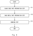
- FIG. 6 is a flowchart showing an example of a method for manufacturing a cutter blade 1 according to the first embodiment.
- the method for manufacturing a cutter blade 1 includes a blade edge part preparation step (Step S11), a base metal part preparation step (Step S12), and a bonding step (Step S13).
- Step S11 a blade edge part preparation step
- Step S12 a base metal part preparation step
- Step S13 a bonding step
- the order of the blade edge part preparation step and the base metal part preparation step may be interchanged. That is, the base metal part preparation step may be performed in the step S11, and the blade edge part preparation step may be performed in the step S12.
- a blade edge part 20 is prepared in the blade edge part preparation step.
- the blade edge part 20 slides along the plate surface 204 of the die plate 201, the plate surface 204 having the holes 205 formed therein, and thereby cuts a plurality of pieces of the material 206 extruded from the holes 205 onto the plate surface 204.
- the blade edge part 20 may have a sliding surface 20a that slides over the plate surface 204.
- the bonding surface 20d of the blade edge part 20 may have surface roughness within a certain microscopic height (Rz: 5 to 30 ⁇ m). Further, in the blade edge part preparation step, the bonding surface 20d of the blade edge part 20, which is to be bonded with the ridge part 12, may have a concave shape.
- a base metal part 10 is prepared in the base metal part preparation step.
- the base metal part 10 may have a bottom surface 11a.
- the base metal part 10 may have an attaching part 11 and a ridge part 12.
- the attaching part 11 is connected a cutter blade holding part 202 which transmits the power for sliding the blade edge part 20 along the plate surface 204.
- the ridge part 12 is opposed to the plate surface 204 with the blade edge part 20 interposed therebetween.
- the blade edge part 20 is bonded to the ridge part 12.
- the bonding surface 12d of the ridge part 12 may have surface roughness within a certain microscopic height (Rz: 5 to 30 ⁇ m). Further, in the base metal part preparation step, the bonding surface 12d of the ridge part 12, which is to be bonded with the blade edge part 20, may have a convex shape.
- the blade edge part 20 is bonded to the base metal part 10 by an adhesive in the bonding step.
- the blade edge part 20 is bonded to the base metal part 10 by an adhesive at a room temperature.
- the blade edge part 20 may be bonded to the base metal part 10 in such a manner that the blade edge part 20 can be replaced with a new one.
- the sliding surface 20a may be bonded to the bottom surface 11a of the base metal part 10 so that they are flush with each other.
- the sliding surface 20a may be bonded to the bottom surface 11a of the attaching part 11 so that they are flush with each other.
- brazing since the brazing has to be carried out in a furnace, a worker or the like cannot see a series of processes. Therefore, any direct work related to the quality of the brazed part cannot be performed, thus making it difficult to control the yield of the brazing.
- the braze-bonded hardened layer does not peel off even when it is heated to a high temperature, the hardened layer worn due to friction and the like cannot be replaced. Therefore, when the cutter blade is used for a certain period of time, it has to be scrapped. Therefore, the manufacturing cost increases.
- the blade edge part 20 is bonded to the base metal part 10 by using an adhesive. Therefore, there is no need to heat the blade edge part 20 and the base metal part 10, which would be necessary in the case of brazing, so that it is possible to prevent them from being deformed. As a result, additional machining, which would otherwise need to be performed to correct the deformation of the blade edge part 20 and the base metal part 10, is not required, so that the manufacturing cost can be greatly reduced.
- a worker or the like who performs the bonding operation between the blade edge part 20 and the base metal part 10 can perform the bonding operation while directly observing the operation. Therefore, it is possible to carry out quality control and thereby to improve the yield.
- the blade edge part 20 bonded by the adhesive can be easily peeled off from the base metal part 10 by, for example, heating them to a predetermined temperature. Therefore, the blade edge part 20 that has been worn due to friction and the like can be easily replaced at a low cost, while the base metal part 10 can be reused.
- the sliding surface 20a of the blade edge part 20 and the bottom surface 11a of the base metal part 10 are flushed with each other. Therefore, the blade edge part 20 can be easily aligned with the ridge part 12 when the blade edge part 20 is bonded to the ridge part 12.
- the base metal part 10 and the blade edge part 20 can be aligned with each other over a flat surface, and can be bonded to each other.
- At least one of the bonding surface 12d of the ridge part 12 and the bonding surface 20d of the blade edge part 20 has surface roughness within a certain microscopic height (Rz: 5 to 30 ⁇ m). As a result, it is possible to improve the adhesion of the adhesive to the bonding surface 12d and the bonding surface 20d. Further, it is possible increase the contact area, and thereby to improve the bonding strength between the bonding surface 12d and the bonding surface 20d.
- the bonding surface 20d of the blade edge part 20 in a concave shape and forming the bonding surface 12d of the ridge part 12 in a convex shape, it is possible to make keeping the adhesive applied to the bonding surface 20d easy at the time of the bonding. For example, when the blade edge part 20 is bonded to the ridge part 12, the adhesive can be prevented from spilling out from the concave part adopted to the bonding surface 20d.
- FIG. 7 is a side view showing an example of a cutter blade 1a according to the first modified example of the first embodiment.
- the cutter blade 1a includes a base metal part 10 and a blade edge part 20, and the blade edge part 20 is fixed to the ridge part 12 of the base metal part 10 by a screw 21.
- the blade edge part 20 is fixed by a screw that reaches, from the dug-in surface 20e, the ridge part 12.
- the fixing by a screw is not limited to a screw reaching, from the dug-in surface 20e, the ridge part 12, but may be a screw reaching, from the dug-in surface 12e, the blade edge part 20 or a screw reaching, from the upper surface 12b, the blade edge part 20 as long as it can fix the blade edge part 20 to the ridge part 12.
- a pin may be used in place of the screw 21.
- the cutter blade 1a includes the blade edge part 20 that slides along the plate surface 204 of the die plate 201, the plate surface 204 having the holes 205 formed therein, and thereby cuts a plurality of pieces of the material 206 extruded from the holes 205 onto the plate surface 204, and the base metal part to which the blade edge part 20 is fixed by a screw or a pin.
- the bonding surface 20d of the blade edge part 20 and the bonding surface 12d of the ridge part 12 may be called (i.e., regarded as) contact surfaces.
- the blade edge part 20 bonded to the base metal part 10 can be replaced with a new one. Further, the heat treatment, which is necessary to peel off the adhesive in order to replace the blade edge part 20 with a new one in the above-described embodiment, can also be made unnecessary. The rest of the configuration and advantageous effects are the same as those described in the first embodiment.
- a cutter blade according to this modified example includes a base metal part 10 and a blade edge part 20, and the blade edge part 20 is fixed to the ridge part 12 of the base metal part 10 by an adhesive and a screw 21 or the like. Note that a pin may be used in place of the screw 21.
- the bonding surface 20d of the blade edge part 20 and the bonding surface 12d of the ridge part 12 are bonded to each other by an adhesive.
- the blade edge part 20 is further fixed to the base metal part 10 by a screw or a pin.
- the blade edge part 20 bonded to the base metal part 10 can be replaced with a new one.
- the adhesive and the screw or the like are used in combination, the blade edge part 20 can be firmly fixed to the base metal part 10.
Landscapes
- Engineering & Computer Science (AREA)
- Mechanical Engineering (AREA)
- Life Sciences & Earth Sciences (AREA)
- Forests & Forestry (AREA)
- Knives (AREA)
- Devices For Post-Treatments, Processing, Supply, Discharge, And Other Processes (AREA)
- Details Of Cutting Devices (AREA)
- Processing And Handling Of Plastics And Other Materials For Molding In General (AREA)
- Processing Of Stones Or Stones Resemblance Materials (AREA)
Abstract
Description
- The present invention relates to a cutter blade and a method for manufacturing a cutter blade.
-
Patent Literature 1 discloses a cutter blade for cutting a resin material extruded from holes formed in a die plate. - Patent Literature 1:
Japanese Unexamined Patent Application Publication No. H11-165316 - When a cutter blade disclosed in
Patent Literature 1 or the like is used, it is conceivable to join a hardened layer to the cutter blade by brazing in order to improve the durability of its blade edge. However, since the cutter blade needs to be heated to about 1,000°C to carry out the brazing, its blade edges are deformed. Since additional machining needs to be performed to correct the deformation of the blade edge, the manufacturing cost increases. - Other problems to be solved and novel features will become apparent from descriptions in this specification and accompanying drawings.
- A cutter blade according to an embodiment includes: a blade edge part configured to slide along a plate surface of a die plate, the plate surface having a hole formed therein, and thereby to cut a material extruded from the hole onto the plate surface; and a base metal part in contact with the blade edge part.
- A method for manufacturing a cutter blade according to an embodiment includes: a blade edge part preparation step of preparing a blade edge part configured to slide along a plate surface of a die plate, the plate surface having a hole formed therein, and thereby to cut a material extruded from the hole onto the plate surface; a base metal part preparation step of preparing a base metal part; and a step of bringing the blade edge part into contact with the base metal part.
- According to the above-described embodiment, it is possible to provide a cutter blade and a method for manufacturing a cutter blade capable of reducing the manufacturing cost.
-
-
Fig. 1 is a configuration diagram showing an example of an underwater granulation apparatus using cutter blades according to a first embodiment; -
Fig. 2 is a perspective diagram showing an example of a die plate in the underwater granulation apparatus using cutter blades according to the first embodiment; -
Fig. 3 is a perspective view showing an example of a cutter blade according to the first embodiment; -
Fig. 4 is a side view showing the example of the cutter blade according to the first embodiment; -
Fig. 5 is a side view showing another example of a cutter blade according to the first embodiment; -
Fig. 6 is a flowchart showing an example of a method for manufacturing a cutter blade according to the first embodiment; and -
Fig. 7 is a side view showing an example of a cutter blade according to a first modified example of the first embodiment. - For clarifying the description, the following description and the drawings are partially omitted and simplified as appropriate. Further, the same symbols are assigned to the same or corresponding components throughout the drawings, and redundant descriptions thereof are omitted as appropriate.
- A cutter blade and a method for manufacturing a cutter blade according to the first embodiment will be described. Firstly, an underwater granulation apparatus will be described as an example of an apparatus using cutter blades. After that, a cutter blade and a method for manufacturing a cutter blade will be described.
-
Fig. 1 is a configuration diagram showing an example of an underwater granulation apparatus using cutter blades according to a first embodiment.Fig. 2 is a perspective view showing an example of a die plate in the underwater granulation apparatus using cutter blades according to the first embodiment. InFig. 1 , an exploded view of a part of the underwater granulation apparatus is shown inside a box. - As shown in
Fig. 1 and Fig. 2 , anunderwater granulation apparatus 200 is connected to the downstream side of anextrusion apparatus 100. Theextrusion apparatus 100 includes adrive unit 101, aspeed reducer 102, acylinder 103 and ascrew 104. Thedrive unit 101, which is, for example, a motor, transmits its rotation adjusted by thespeed reducer 102 to thescrew 104. In this way, thescrew 104 is rotated by the adjusted power source of thedrive unit 101 inside thecylinder 103. - A
material 206 supplied into thecylinder 103 from a predetermined part of thecylinder 103 is extruded to theunderwater granulation apparatus 200 side by the rotatingscrew 104. The suppliedmaterial 206 is, for example, a resin material. Theextrusion apparatus 100 plasticizes and kneads, for example, a resin material by heating it inside thecylinder 103 and by the rotation of thescrew 104, and extrudes the plasticized and kneaded resin material to theunderwater granulation apparatus 200 as a molten resin. - The
underwater granulation apparatus 200 includes adie plate 201, a cutterblade holding part 202, and adrive unit 203. Thedie plate 201 and the cutterblade holding part 202 are disposed underwater. The dieplate 201 has aplate surface 204. A plurality ofholes 205 are formed in theplate surface 204. Thematerial 206 extruded by the rotatingscrew 104 is extruded from theholes 205 formed in theplate surface 204 onto theplate surface 204. Thematerial 206 extruded onto theplate surface 204 is, for example, a molten resin. InFig. 2 , only some of theholes 205 and some of pieces of thematerial 206 extruded therefrom are indicated by reference numerals in order to simplify the drawing. - The die
plate 201 and theplate surface 204 have a central axis C. The cutterblade holding part 202 is disposed so as to be opposed to thedie plate 201. The cutterblade holding part 202 is rotated about the central axis C by the power source of thedrive unit 203. The cutterblade holding part 202 holds a plurality ofcutter blades 1. InFig. 1 , only some of thecutter blades 1 are indicated by reference numerals in order to simplify the drawing. - For example, the
cutter blades 1 are held (i.e., positioned) at equal intervals on the peripheral edge of the circular cutterblade holding part 202. Further, as the cutterblade holding part 202 rotates, each of thecutter blades 1 slides over theplate surface 204. As a result, thecutter blades 1 cut a plurality of pieces of thematerial 206 extruded from theholes 205 onto theplate surface 204. For example, a plurality of pieces of the molten resin extruded from theholes 205 onto theplate surface 204 are cut by thecutter blades 1. The plurality of cut pieces of the molten resin solidify underwater and become resin pellets. - Next, the
cutter blade 1 will be described.Fig. 3 is a perspective view showing an example of thecutter blade 1 according to the first embodiment.Fig. 4 is a side view showing the example of thecutter blade 1 according to the first embodiment. As shown inFigs. 3 and4 , thecutter blade 1 includes abase metal part 10 and ablade edge part 20. Theblade edge part 20 is bonded to thebase metal part 10 by an adhesive. - Note that an XYZ-orthogonal axis system is introduced to explain the
cutter blade 1. In the state in which thecutter blade 1 is placed over theplate surface 204, the direction perpendicular to theplate surface 204 is defined as the Z-axis direction. The direction in which the blade edge extends is defined as the Y-direction. The direction perpendicular to the Y- and Z-axis directions is defined as the X-axis direction. - The
base metal part 10 includes an attachingpart 11 and aridge part 12. The attachingpart 11 and theridge part 12 are connected to each other in the Y-axis direction. As its material, thebase metal part 10 contains, for example, stainless steel. Note that the material of thebase metal part 10 is not limited to the material containing stainless steel, but may contain other metals, ceramics, plastics, or the like. - The attaching
part 11 is connected the cutterblade holding part 202 which transmits the power for sliding thecutter blade 1 along theplate surface 204. The attachingpart 11 is formed, for example, in a part of thebase metal part 10 on the +Y axis direction side thereof. The attachingpart 11 has, for example, a quadrangular prism shape, and has abottom surface 11a and anupper surface 11b. Thebottom surface 11a is the surface on the -Z axis direction side, and theupper surface 11b is the surface on the +Z axis direction side. - In the attaching
part 11, holes 13, which are used to connect the attachingpart 11 to the cutterblade holding part 202, are formed. The number ofholes 13 may be only one or may be more than one. Theholes 13 penetrate (i.e., extend) from theupper surface 11b to thebottom surface 11a. For example, thecutter blade 1 is fixed to the cutterblade holding part 202 by inserting bolts into theholes 13 of the attachingpart 11 and holes formed in the cutterblade holding part 202. Note that instead of theholes 13, grooves or the like may be formed in the attachingpart 11 as long as they can be used to connect the attachingpart 11 to the cutterblade holding part 202. - The
ridge part 12 is opposed to theplate surface 204 with theblade edge part 20 interposed therebetween. Theblade edge part 20 is bonded to theridge part 12. Theridge part 12 is formed, for example, in a part of thebase metal part 10 on the -Y axis direction side thereof. Theridge part 12 extends, for example, in the Y-axis direction. Theridge part 12 has anupper surface 12b, aninclined surface 12c, abonding surface 12d, a dug-insurface 12e, and arear surface 12f. Theridge part 12 has a columnar shape extending in the Y-axis direction, with theupper surface 12b, theinclined surface 12c, thebonding surface 12d, the dug-insurface 12e, and therear surface 12f being its peripheral surfaces. - The
upper surface 12b is, for example, flush with theupper surface 11b of the attachingpart 11. Theinclined surface 12c is inclined with respect to theupper surface 12b. The angle between theupper surface 12b and theinclined surface 12c is, for example, 135 [deg]. Therefore, the angle between theinclined surface 12c and a plane extending from (i.e., parallel to) theupper surface 12b is 45 [deg]. - The
bonding surface 12d faces in the -Z axis direction. Thebonding surface 12d is the surface to be bonded with theblade edge part 20. Thebonding surface 12d of theridge part 12 is shaped so that it is engaged with thebonding surface 20d of theblade edge part 20. For example, thebonding surface 12d of theridge part 12 has a convex shape. Specifically, the cross section of thebonding surface 12d perpendicular to the Y-axis direction is convex. In this case, the cross section of thebonding surface 20d of theblade edge part 20 perpendicular to the Y-axis direction is concave. - Note that the
bonding surface 12d of theridge part 12 may have a concave shape and thebonding surface 20d of theblade edge part 20 may have a convex shape. Alternatively, thebonding surface 12d of theridge part 12 and thebonding surface 20d of theblade edge part 20 may be both planar (i.e., flat) as shown inFig. 5 . In the case where thebonding surface 12d of theridge part 12 and thebonding surface 20d of theblade edge part 20 are both planar (i.e., flat), thebonding surface 12d and thebonding surface 20d may be parallel to thebottom surface 11a, or thebonding surface 12d and thebonding surface 20d may be inclined with respect to thebottom surface 11a. For example, thebonding surface 12d and thebonding surface 20d may be perpendicular to theinclined surface 12c. - The
bonding surface 12d may have surface roughness within a certain microscopic height (Rz: 5 to 30 µm). As a result, the bonding strength of the adhesive can be improved. - The dug-in
surface 12e is a surface opposed to theupper surface 12b and theinclined surface 12c. The dug-insurface 12e is, for example, curved in a concave shape. The dug-insurface 12e is smoothly connected to the dug-insurface 20e. Therear surface 12f faces in the +X axis direction. - The
blade edge part 20 is a part that slides over theplate surface 204. Theblade edge part 20 slides along theplate surface 204 of thedie plate 201 having theplate surface 204 in which theholes 205 are formed, and thereby cuts a plurality of pieces of the material 206 extruded from theholes 205 onto theplate surface 204. As its material, theblade edge part 20 contains, for example, a hardened layer such as a TiC cermet. Note that the material of theblade edge part 20 is not limited to those containing a TiC cermet, but may contain other metals, ceramics, plastics, or the like. - The
blade edge part 20 is bonded to thebase metal part 10 by an adhesive. The adhesive is, for example, an epoxy adhesive. The adhesive is preferably one that can be easily peeled off when it is heated to a predetermined temperature. In this way, theblade edge part 20 bonded to thebase metal part 10 can be replaced with a new one. - The
blade edge part 20 extends, for example, in the Y-axis direction. Theblade edge part 20 includes a slidingsurface 20a, aninclined surface 20c, abonding surface 20d, and a dug-insurface 20e. Theblade edge part 20 has, for example, a columnar shape extending in the Y-axis direction, with the slidingsurface 20a, theinclined surface 20c, thebonding surface 20d, and dug-insurface 20e being its peripheral surfaces. - The sliding
surface 20a slides over theplate surface 204. As the slidingsurface 20a slides over theplate surface 204, a plurality of pieces of the material 206 extruded from theholes 205 onto theplate surface 204 are cut by the blade edge. The slidingsurface 20a is shaped so as to conform to the shape of theplate surface 204 so that theplate surface 204 can slide thereover. In the case where theplate surface 204 is planar (i.e., flat), the slidingsurface 20a is also planar (i.e., flat). In the case where the cross section of theplate surface 204 perpendicular to the X-axis direction is curved, the cross section of the slidingsurface 20a perpendicular to the X-axis direction may also be curved in conformity with the curvature of theplate surface 204. - In the case where the sliding
surface 20a is planar (i.e., flat), the slidingsurface 20a may be flush with thebottom surface 11a of the attachingpart 11 in thebase metal part 10. Therefore, thebase metal part 10 has thebottom surface 11a that is flush with the slidingsurface 20a. In this way, theblade edge part 20 can be easily aligned with thebase metal part 10 when theblade edge part 20 is bonded to thebase metal part 10. - The
inclined surface 20c is inclined with respect to the slidingsurface 20a. For example, theinclined surface 20c is inclined by 45 [deg] with respect to the slidingsurface 20a. The blade edge is formed by the slidingsurface 20a and theinclined surface 20c. That is, the angle between the slidingsurface 20a and theinclined surface 20c forms the blade edge. The blade edge extends in the Y-axis direction. Theinclined surface 20c is flush with theinclined surface 12c. Therefore, a plurality of pieces of the material 206 cut by the blade edge smoothly move over theinclined surface 20c and theinclined surface 12c. Consequently, it is possible to prevent the cut pieces of the material 206 from being damaged. - The
bonding surface 20d is a surface opposed to the slidingsurface 20a. Thebonding surface 20d is the surface to be bonded with thebase metal part 10. Thebonding surface 20d is bonded to thebonding surface 12d of theridge part 12. Thebonding surface 20d of theblade edge part 20 is shaped so that it is engaged with thebonding surface 12d of theridge part 12. For example, thebonding surface 20d of theblade edge part 20 has a concave shape. Specifically, the cross section of thebonding surface 20d of theblade edge part 20 perpendicular to the Y-axis direction is concave. In this case, the cross section of thebonding surface 12d of theridge part 12 perpendicular to the Y-axis direction is also convex. - Alternatively, as described above, the
bonding surface 12d of theridge part 12 may have a concave shape and thebonding surface 20d of theblade edge part 20 may have a convex shape, or thebonding surface 12d of theridge part 12 and thebonding surface 20d of theblade edge part 20 may be both planar (i.e., flat). - The
bonding surface 20d may have surface roughness within a certain microscopic height (Rz: 5 to 30 µm). As a result, the bonding strength of the adhesive can be improved. - The dug-in
surface 20e is a surface opposed to theinclined surface 20c. The dug-insurface 20e is, for example, curved in a concave shape. The dug-insurface 20e is smoothly connected to the dug-insurface 12e. - Next, a method for manufacturing a
cutter blade 1 according to this embodiment will be described.Fig. 6 is a flowchart showing an example of a method for manufacturing acutter blade 1 according to the first embodiment. - As shown in
Fig. 6 , the method for manufacturing acutter blade 1 includes a blade edge part preparation step (Step S11), a base metal part preparation step (Step S12), and a bonding step (Step S13). Note that the order of the blade edge part preparation step and the base metal part preparation step may be interchanged. That is, the base metal part preparation step may be performed in the step S11, and the blade edge part preparation step may be performed in the step S12. - Firstly, as shown in a step S11, a
blade edge part 20 is prepared in the blade edge part preparation step. Theblade edge part 20 slides along theplate surface 204 of thedie plate 201, theplate surface 204 having theholes 205 formed therein, and thereby cuts a plurality of pieces of the material 206 extruded from theholes 205 onto theplate surface 204. In the blade edge part preparation step, theblade edge part 20 may have a slidingsurface 20a that slides over theplate surface 204. - In the blade edge part preparation step, the
bonding surface 20d of theblade edge part 20 may have surface roughness within a certain microscopic height (Rz: 5 to 30 µm). Further, in the blade edge part preparation step, thebonding surface 20d of theblade edge part 20, which is to be bonded with theridge part 12, may have a concave shape. - Then, as shown in a step S12, a
base metal part 10 is prepared in the base metal part preparation step. In the base metal part preparation step, thebase metal part 10 may have abottom surface 11a. Further, in the base metal part preparation step, thebase metal part 10 may have an attachingpart 11 and aridge part 12. The attachingpart 11 is connected a cutterblade holding part 202 which transmits the power for sliding theblade edge part 20 along theplate surface 204. Theridge part 12 is opposed to theplate surface 204 with theblade edge part 20 interposed therebetween. Theblade edge part 20 is bonded to theridge part 12. - In the base metal part preparation step, the
bonding surface 12d of theridge part 12 may have surface roughness within a certain microscopic height (Rz: 5 to 30 µm). Further, in the base metal part preparation step, thebonding surface 12d of theridge part 12, which is to be bonded with theblade edge part 20, may have a convex shape. - Next, as shown in a step S13, the
blade edge part 20 is bonded to thebase metal part 10 by an adhesive in the bonding step. For example, theblade edge part 20 is bonded to thebase metal part 10 by an adhesive at a room temperature. In the bonding step, theblade edge part 20 may be bonded to thebase metal part 10 in such a manner that theblade edge part 20 can be replaced with a new one. Further, in the bonding step, the slidingsurface 20a may be bonded to thebottom surface 11a of thebase metal part 10 so that they are flush with each other. Specifically, in the bonding step, the slidingsurface 20a may be bonded to thebottom surface 11a of the attachingpart 11 so that they are flush with each other. Through the above-described processes, thecutter blade 1 can be manufactured. - Next, a comparative example will be described before describing advantageous effects of the above-described embodiment. After that, the advantageous effects of the above-described embodiment will be described while comparing them with those of the comparative example.
- For example, as a comparative example, in the case of a cutter blade disclosed in
Patent Literature 1 or the like, it is conceivable to join a hardened layer to the cutter blade by brazing in order to improve the durability of its blade edge. However, since the cutter blade needs to be heated to about 1,000°C to carry out the brazing, its blade edges are deformed. Since additional machining needs to be performed to correct the deformation of the blade edge, the manufacturing cost increases. - Further, since the brazing has to be carried out in a furnace, a worker or the like cannot see a series of processes. Therefore, any direct work related to the quality of the brazed part cannot be performed, thus making it difficult to control the yield of the brazing.
- Further, since the braze-bonded hardened layer does not peel off even when it is heated to a high temperature, the hardened layer worn due to friction and the like cannot be replaced. Therefore, when the cutter blade is used for a certain period of time, it has to be scrapped. Therefore, the manufacturing cost increases.
- Next, advantageous effects of this embodiment will be explained. In the
cutter blade 1 according to this embodiment, theblade edge part 20 is bonded to thebase metal part 10 by using an adhesive. Therefore, there is no need to heat theblade edge part 20 and thebase metal part 10, which would be necessary in the case of brazing, so that it is possible to prevent them from being deformed. As a result, additional machining, which would otherwise need to be performed to correct the deformation of theblade edge part 20 and thebase metal part 10, is not required, so that the manufacturing cost can be greatly reduced. - A worker or the like who performs the bonding operation between the
blade edge part 20 and thebase metal part 10 can perform the bonding operation while directly observing the operation. Therefore, it is possible to carry out quality control and thereby to improve the yield. - The
blade edge part 20 bonded by the adhesive can be easily peeled off from thebase metal part 10 by, for example, heating them to a predetermined temperature. Therefore, theblade edge part 20 that has been worn due to friction and the like can be easily replaced at a low cost, while thebase metal part 10 can be reused. - The sliding
surface 20a of theblade edge part 20 and thebottom surface 11a of thebase metal part 10 are flushed with each other. Therefore, theblade edge part 20 can be easily aligned with theridge part 12 when theblade edge part 20 is bonded to theridge part 12. For example, thebase metal part 10 and theblade edge part 20 can be aligned with each other over a flat surface, and can be bonded to each other. - At least one of the
bonding surface 12d of theridge part 12 and thebonding surface 20d of theblade edge part 20 has surface roughness within a certain microscopic height (Rz: 5 to 30 µm). As a result, it is possible to improve the adhesion of the adhesive to thebonding surface 12d and thebonding surface 20d. Further, it is possible increase the contact area, and thereby to improve the bonding strength between thebonding surface 12d and thebonding surface 20d. - By forming one of the
bonding surface 20d of theblade edge part 20 and thebonding surface 12d of theridge part 12 in a convex shape and forming the other in a concave shape, it is possible increase the contact area, and thereby to improve the bonding strength. Further, by the engagement of the concave bonding surface with the convex bonding surface, the bonding strength between these bonding surfaces can be improved. - By forming the
bonding surface 20d of theblade edge part 20 in a concave shape and forming thebonding surface 12d of theridge part 12 in a convex shape, it is possible to make keeping the adhesive applied to thebonding surface 20d easy at the time of the bonding. For example, when theblade edge part 20 is bonded to theridge part 12, the adhesive can be prevented from spilling out from the concave part adopted to thebonding surface 20d. - Next, a first modified example of the first embodiment will be described. In the above-described embodiment, the
blade edge part 20 is bonded to thebase metal part 10 by an adhesive. However, instead of using the adhesive, theblade edge part 20 may be fixed by using a screw or the like.Fig. 7 is a side view showing an example of acutter blade 1a according to the first modified example of the first embodiment. - As shown in
Fig. 7 , thecutter blade 1a includes abase metal part 10 and ablade edge part 20, and theblade edge part 20 is fixed to theridge part 12 of thebase metal part 10 by ascrew 21. For example, theblade edge part 20 is fixed by a screw that reaches, from the dug-insurface 20e, theridge part 12. Note that the fixing by a screw is not limited to a screw reaching, from the dug-insurface 20e, theridge part 12, but may be a screw reaching, from the dug-insurface 12e, theblade edge part 20 or a screw reaching, from theupper surface 12b, theblade edge part 20 as long as it can fix theblade edge part 20 to theridge part 12. Alternatively, a pin may be used in place of thescrew 21. - Therefore, the
cutter blade 1a according to this modified example includes theblade edge part 20 that slides along theplate surface 204 of thedie plate 201, theplate surface 204 having theholes 205 formed therein, and thereby cuts a plurality of pieces of the material 206 extruded from theholes 205 onto theplate surface 204, and the base metal part to which theblade edge part 20 is fixed by a screw or a pin. In this case, thebonding surface 20d of theblade edge part 20 and thebonding surface 12d of theridge part 12 may be called (i.e., regarded as) contact surfaces. - Even in the
cutter blade 1a according to this modified example, theblade edge part 20 bonded to thebase metal part 10 can be replaced with a new one. Further, the heat treatment, which is necessary to peel off the adhesive in order to replace theblade edge part 20 with a new one in the above-described embodiment, can also be made unnecessary. The rest of the configuration and advantageous effects are the same as those described in the first embodiment. - Next, a second modified example of the first embodiment will be described. In the above-described second modified example, the
blade edge part 20 is fixed to thebase metal part 10 by a screw or the like. In contrast, in this modified example, an adhesive and a screw or the like are both used in combination. Specifically, a cutter blade according to this modified example includes abase metal part 10 and ablade edge part 20, and theblade edge part 20 is fixed to theridge part 12 of thebase metal part 10 by an adhesive and ascrew 21 or the like. Note that a pin may be used in place of thescrew 21. - For example, the
bonding surface 20d of theblade edge part 20 and thebonding surface 12d of theridge part 12 are bonded to each other by an adhesive. In addition, theblade edge part 20 is further fixed to thebase metal part 10 by a screw or a pin. Even in this modified example, theblade edge part 20 bonded to thebase metal part 10 can be replaced with a new one. Further, since the adhesive and the screw or the like are used in combination, theblade edge part 20 can be firmly fixed to thebase metal part 10. The rest of the configuration and advantageous effects are the same as those described in the first embodiment and the first modified example. - The present invention made by the inventors of the present application has been described above in a concrete manner based on embodiments. However, the present invention is not limited to the above-described embodiments, and needless to say, various modifications can be made without departing from the spirit and scope of the invention.
- This application is based upon and claims the benefit of priority from
Japanese patent application No. 2020-210135, filed on December 18, 2020 -
- 1, 1a
- CUTTER BLADE
- 10
- BASE METAL PART
- 11
- ATTACHING PART
- 11a
- BOTTOM SURFACE
- 11b
- TOP SURFACE
- 12
- RIDGE PART
- 12b
- TOP SURFACE
- 12c
- INCLINED SURFACE
- 12d
- BONDING SURFACE
- 12e
- DUG-IN SURFACE
- 12f
- REAR SURFACE
- 13
- HOLE
- 20
- BLADE EDGE PART
- 20a
- SLIDING SURFACE
- 20c
- INCLINED SURFACE
- 20d
- BONDING SURFACE
- 20e
- DUG-IN SURFACE
- 21
- SCREW
- 100
- EXTRUSION APPARATUS
- 101
- DRIVE UNIT
- 102
- SPEED REDUCER
- 103
- CYLINDER
- 104
- SCREW
- 200
- UNDERWATER GRANULATION APPARATUS
- 201
- DIE PLATE
- 202
- CUTTER BLADE HOLDING PART
- 203
- DRIVE UNIT
- 204
- PLATE SURFACE
- 205
- HOLE
- 206
- MATERIAL
Claims (16)
- A cutter blade comprising:a blade edge part configured to slide along a plate surface of a die plate, the plate surface having a hole formed therein, and thereby to cut a material extruded from the hole onto the plate surface; anda base metal part to which the blade edge part is bonded by an adhesive.
- The cutter blade according to Claim 1, wherein the blade edge part bonded to the base metal part can be replaced.
- The cutter blade according to Claim 1 or 2, whereinthe blade edge part has a sliding surface configured to slide over the plate surface, andthe base metal part has a bottom surface that is flush with the sliding surface.
- The cutter blade according to Claim 3, wherein
the base metal part comprises:an attaching part configured to be connected to a cutter blade holding part configured to transmit power for sliding the cutter blade along the plate surface; anda ridge part opposed to the plate surface with the blade edge part interposed therebetween, the blade edge part being bonded to the ridge part, anda bottom surface of the attaching part is flush with the sliding surface. - The cutter blade according to Claim 4, wherein regarding bonding surfaces between the base metal part and the blade edge part, at least one of a bonding surface of the ridge part and a bonding surface of the blade edge part has surface roughness within a microscopic height Rz of 5 to 30 µm.
- The cutter blade according to Claim 4 or 5, wherein regarding bonding surfaces between the base metal part and the blade edge part, a bonding surface of the ridge part has a convex shape and a bonding surface of the blade edge part has a concave shape.
- The cutter blade according to Claim 4 or 5, wherein regarding bonding surfaces between the ridge part and the blade edge part, a bonding surface of the ridge part is planar and a bonding surface of the blade edge part is also planar.
- The cutter blade according to any one of Claims 1 to 7, wherein the blade edge part is further fixed to the base metal part by a screw or a pin.
- A method for manufacturing a cutter blade, comprising:a blade edge part preparation step of preparing a blade edge part configured to slide along a plate surface of a die plate, the plate surface having a hole formed therein, and thereby to cut a material extruded from the hole onto the plate surface;a base metal part preparation step of preparing a base metal part; anda bonding step of bonding the blade edge part to the base metal part by an adhesive.
- The method for manufacturing a cutter blade according to Claim 9, wherein in the bonding step, the blade edge part is bonded to the base metal part in such a manner that the blade edge part can be replaced.
- The method for manufacturing a cutter blade according to Claim 9 or 10, whereinin the blade edge part preparation step, the blade edge part is prepared so that the blade edge part has a sliding surface configured to slide over the plate surface,in the base metal part preparation step, the base metal part is prepared so that the base metal part has a bottom surface, andin the bonding step, the sliding surface is bonded to the bottom surface of the base metal part so that the sliding surface is flush with the bottom surface.
- The method for manufacturing a cutter blade according to Claim 11, wherein
in the base metal part preparation step, the base metal part is prepared so that the base metal part comprises:an attaching part configured to be connected to a cutter blade holding part configured to transmit power for sliding the cutter blade along the plate surface; anda ridge part opposed to the plate surface with the blade edge part interposed therebetween, the blade edge part being bonded to the ridge part, andin the bonding step, the sliding surface is bonded to the bottom surface of the attaching part so that the sliding surface is flush with the bottom surface. - The method for manufacturing a cutter blade according to Claim 12, wherein in at least one of the blade edge part preparation step and the base metal part preparation step, regarding bonding surfaces between the base metal part and the blade edge part, at least one of a bonding surface of the ridge part and a bonding surface of the blade edge part has surface roughness within a microscopic height Rz of 5 to 30 µm.
- The method for manufacturing a cutter blade according to Claim 12 or 13, whereinin the blade edge part preparation step, a bonding surface of the blade edge part, which is to be bonded with the ridge part, is formed in a concave shape, andin the base metal part preparation step, a bonding surface of the ridge part, which is to be bonded with the blade edge part, is formed in a convex shape.
- The method for manufacturing a cutter blade according to Claim 12 or 13, whereinin the blade edge part preparation step, a bonding surface of the blade edge part, which is to be bonded with the ridge part, is formed in a planar shape, andin the base metal part preparation step, a bonding surface of the ridge part, which is to be bonded with the blade edge part, is also formed in a planar shape.
- The method for manufacturing a cutter blade according to any one of Claims 9 to 15, wherein in the bonding step, the blade edge part is further fixed to the base metal part by a screw or a pin.
Applications Claiming Priority (2)
| Application Number | Priority Date | Filing Date | Title |
|---|---|---|---|
| JP2020210135A JP7590173B2 (en) | 2020-12-18 | 2020-12-18 | Cutter blade and manufacturing method thereof |
| PCT/JP2021/028456 WO2022130678A1 (en) | 2020-12-18 | 2021-07-30 | Cutter blade and method for manufacturing cutting blade |
Publications (4)
| Publication Number | Publication Date |
|---|---|
| EP4265382A1 true EP4265382A1 (en) | 2023-10-25 |
| EP4265382A4 EP4265382A4 (en) | 2024-11-13 |
| EP4265382B1 EP4265382B1 (en) | 2025-12-17 |
| EP4265382C0 EP4265382C0 (en) | 2025-12-17 |
Family
ID=82057527
Family Applications (1)
| Application Number | Title | Priority Date | Filing Date |
|---|---|---|---|
| EP21906044.9A Active EP4265382B1 (en) | 2020-12-18 | 2021-07-30 | Cutter blade and method for manufacturing cutting blade |
Country Status (6)
| Country | Link |
|---|---|
| US (1) | US20240001573A1 (en) |
| EP (1) | EP4265382B1 (en) |
| JP (1) | JP7590173B2 (en) |
| KR (1) | KR20230119639A (en) |
| CN (1) | CN116710243A (en) |
| WO (1) | WO2022130678A1 (en) |
Families Citing this family (2)
| Publication number | Priority date | Publication date | Assignee | Title |
|---|---|---|---|---|
| JP7778643B2 (en) | 2022-06-15 | 2025-12-02 | 株式会社ブリヂストン | Tire manufacturing method |
| JP2024072427A (en) | 2022-11-16 | 2024-05-28 | 株式会社日本製鋼所 | Cutter blade, granulator, and method for manufacturing cutter blade |
Family Cites Families (21)
| Publication number | Priority date | Publication date | Assignee | Title |
|---|---|---|---|---|
| JP2655965B2 (en) * | 1991-12-26 | 1997-09-24 | 積水化成品工業株式会社 | Resin hot cutting equipment |
| JPH0740112U (en) * | 1993-12-27 | 1995-07-18 | 株式会社神戸製鋼所 | Pelletizer |
| JP3009165U (en) * | 1994-09-13 | 1995-03-28 | 有限会社森田精機 | Canna blade for cutting edges |
| JP2905472B2 (en) * | 1997-03-04 | 1999-06-14 | 株式会社神戸製鋼所 | Underwater cut granulation apparatus, knife used in the apparatus, and underwater cut granulation method using the knife |
| JP3471592B2 (en) | 1997-12-03 | 2003-12-02 | 株式会社神戸製鋼所 | Knife holder for resin granulator |
| US6537050B1 (en) * | 1998-03-02 | 2003-03-25 | Kabushiki Kaisha Kobe Seiko Sho | Underwater cutting granulating device |
| DK1124670T3 (en) * | 1999-08-30 | 2004-04-05 | Joachim Kozlowski | Machine knife for pruning books and similar items |
| JP2002214993A (en) * | 2001-01-17 | 2002-07-31 | Bando Chem Ind Ltd | Blade for electrophotographic equipment |
| US7181993B2 (en) * | 2001-02-06 | 2007-02-27 | Good Earth Tool Company | Apparatus and process for cutting of extruded material |
| JP3731153B2 (en) * | 2001-03-29 | 2006-01-05 | 兼房株式会社 | Bonding layer protection structure for wear resistant parts |
| US8186991B2 (en) * | 2004-02-27 | 2012-05-29 | Jmp Industries, Inc. | Extruder system and cutting assembly |
| DE102004056771A1 (en) * | 2004-11-24 | 2006-06-01 | Lutz Industria S.A. | Blade and method of making the same |
| JP5186413B2 (en) * | 2009-02-26 | 2013-04-17 | 株式会社神戸製鋼所 | Resin granulator |
| WO2010148208A1 (en) * | 2009-06-17 | 2010-12-23 | Gala Industries, Inc. | Solid one-piece cutter hub and blade combination |
| DE102012101866B3 (en) * | 2012-03-06 | 2013-05-16 | Frielinghaus Gmbh | Non-twisting feed mixer blade |
| CN202639368U (en) * | 2012-04-27 | 2013-01-02 | 沈阳远大铝业工程有限公司 | Machine-clamping replaceable type group angle cutter |
| CN203170419U (en) * | 2013-03-19 | 2013-09-04 | 中山斯瑞德环保设备科技有限公司 | Crusher tool convenient for replacing blade |
| US20150343667A1 (en) * | 2014-05-30 | 2015-12-03 | Kennametal Inc. | Knives comprising composite materials for use with pelletizing dies |
| CN107073751B (en) * | 2014-11-14 | 2020-07-21 | 阿蒙Dpi公司 | Granulating cutter with detachable cutting edge |
| DE102017223708A1 (en) * | 2017-12-22 | 2019-06-27 | Coperion Gmbh | Cutter head and method for granulating material strands |
| NL2021389B1 (en) * | 2018-07-24 | 2020-01-30 | Vmi Holland Bv | Round knife, cutting assembly and method for cutting tire components |
-
2020
- 2020-12-18 JP JP2020210135A patent/JP7590173B2/en active Active
-
2021
- 2021-07-30 WO PCT/JP2021/028456 patent/WO2022130678A1/en not_active Ceased
- 2021-07-30 CN CN202180080566.8A patent/CN116710243A/en active Pending
- 2021-07-30 EP EP21906044.9A patent/EP4265382B1/en active Active
- 2021-07-30 US US18/037,554 patent/US20240001573A1/en active Pending
- 2021-07-30 KR KR1020237019150A patent/KR20230119639A/en active Pending
Also Published As
| Publication number | Publication date |
|---|---|
| KR20230119639A (en) | 2023-08-16 |
| JP7590173B2 (en) | 2024-11-26 |
| US20240001573A1 (en) | 2024-01-04 |
| EP4265382B1 (en) | 2025-12-17 |
| WO2022130678A1 (en) | 2022-06-23 |
| EP4265382C0 (en) | 2025-12-17 |
| CN116710243A (en) | 2023-09-05 |
| EP4265382A4 (en) | 2024-11-13 |
| JP2022096887A (en) | 2022-06-30 |
Similar Documents
| Publication | Publication Date | Title |
|---|---|---|
| EP4265382B1 (en) | Cutter blade and method for manufacturing cutting blade | |
| US20080121078A1 (en) | Method of and apparatus for working structure | |
| JP4842015B2 (en) | Cutter wheel tip holder for brittle materials | |
| US7181993B2 (en) | Apparatus and process for cutting of extruded material | |
| US20240025082A1 (en) | Cutter blade and granulation apparatus | |
| EP4620640A1 (en) | Cutter blade, granulating device, and method for manufacturing cutter blade | |
| CN115533973B (en) | A processing method for composite material thin plate and composite material thin plate | |
| JP2000153553A (en) | Type roll | |
| CN112935317B (en) | Method for machining part with opposite annular bosses | |
| CN214517645U (en) | Nonstandard double-edge cutting-off and grooving blade for numerical control indexable | |
| CN102114551A (en) | Method and system for parallel precision finishing | |
| JP3186341B2 (en) | Indexable face milling | |
| CN107457439B (en) | Cutting accessory and application thereof | |
| CN212920475U (en) | A cutting and forming device for additively manufacturing gradient polymer composite components | |
| KR20220120018A (en) | rivet screw drill | |
| JP4626347B2 (en) | Blade holder | |
| CN222078064U (en) | Polarizer Milling Cutter | |
| CN222242926U (en) | Reamer for machining inner holes in satellite carbon fiber parts | |
| JP2007098340A (en) | Rotary cutter and its adjustment method | |
| CN218638661U (en) | Rubber ring lining device for disc shear | |
| CN120773164A (en) | Processing device and processing method of amorphous strip and nanocrystalline strip | |
| US10512974B1 (en) | Diamond machining tool | |
| JP2003145484A (en) | Round blade for slitter and slitting method using the same | |
| CN117556645A (en) | Surface roughness Sz-based composite member profile milling parameter determination method | |
| CN116618757A (en) | A kind of surface secondary structure preparation method |
Legal Events
| Date | Code | Title | Description |
|---|---|---|---|
| STAA | Information on the status of an ep patent application or granted ep patent |
Free format text: STATUS: THE INTERNATIONAL PUBLICATION HAS BEEN MADE |
|
| PUAI | Public reference made under article 153(3) epc to a published international application that has entered the european phase |
Free format text: ORIGINAL CODE: 0009012 |
|
| STAA | Information on the status of an ep patent application or granted ep patent |
Free format text: STATUS: REQUEST FOR EXAMINATION WAS MADE |
|
| 17P | Request for examination filed |
Effective date: 20230626 |
|
| AK | Designated contracting states |
Kind code of ref document: A1 Designated state(s): AL AT BE BG CH CY CZ DE DK EE ES FI FR GB GR HR HU IE IS IT LI LT LU LV MC MK MT NL NO PL PT RO RS SE SI SK SM TR |
|
| DAV | Request for validation of the european patent (deleted) | ||
| DAX | Request for extension of the european patent (deleted) | ||
| A4 | Supplementary search report drawn up and despatched |
Effective date: 20241014 |
|
| RIC1 | Information provided on ipc code assigned before grant |
Ipc: B29B 9/06 20060101ALI20241008BHEP Ipc: B26D 7/26 20060101ALI20241008BHEP Ipc: B26D 1/28 20060101AFI20241008BHEP |
|
| GRAP | Despatch of communication of intention to grant a patent |
Free format text: ORIGINAL CODE: EPIDOSNIGR1 |
|
| STAA | Information on the status of an ep patent application or granted ep patent |
Free format text: STATUS: GRANT OF PATENT IS INTENDED |
|
| INTG | Intention to grant announced |
Effective date: 20250910 |
|
| GRAS | Grant fee paid |
Free format text: ORIGINAL CODE: EPIDOSNIGR3 |
|
| GRAA | (expected) grant |
Free format text: ORIGINAL CODE: 0009210 |
|
| STAA | Information on the status of an ep patent application or granted ep patent |
Free format text: STATUS: THE PATENT HAS BEEN GRANTED |
|
| AK | Designated contracting states |
Kind code of ref document: B1 Designated state(s): AL AT BE BG CH CY CZ DE DK EE ES FI FR GB GR HR HU IE IS IT LI LT LU LV MC MK MT NL NO PL PT RO RS SE SI SK SM TR |
|
| REG | Reference to a national code |
Ref country code: CH Ref legal event code: F10 Free format text: ST27 STATUS EVENT CODE: U-0-0-F10-F00 (AS PROVIDED BY THE NATIONAL OFFICE) Effective date: 20251217 Ref country code: GB Ref legal event code: FG4D |
|
| REG | Reference to a national code |
Ref country code: DE Ref legal event code: R096 Ref document number: 602021044774 Country of ref document: DE |
|
| U01 | Request for unitary effect filed |
Effective date: 20260113 |
|
| U07 | Unitary effect registered |
Designated state(s): AT BE BG DE DK EE FI FR IT LT LU LV MT NL PT RO SE SI Effective date: 20260116 |
|
| PG25 | Lapsed in a contracting state [announced via postgrant information from national office to epo] |
Ref country code: NO Free format text: LAPSE BECAUSE OF FAILURE TO SUBMIT A TRANSLATION OF THE DESCRIPTION OR TO PAY THE FEE WITHIN THE PRESCRIBED TIME-LIMIT Effective date: 20260317 |
|
| PG25 | Lapsed in a contracting state [announced via postgrant information from national office to epo] |
Ref country code: HR Free format text: LAPSE BECAUSE OF FAILURE TO SUBMIT A TRANSLATION OF THE DESCRIPTION OR TO PAY THE FEE WITHIN THE PRESCRIBED TIME-LIMIT Effective date: 20251217 |
|
| PG25 | Lapsed in a contracting state [announced via postgrant information from national office to epo] |
Ref country code: RS Free format text: LAPSE BECAUSE OF FAILURE TO SUBMIT A TRANSLATION OF THE DESCRIPTION OR TO PAY THE FEE WITHIN THE PRESCRIBED TIME-LIMIT Effective date: 20260317 |