EP4264594B1 - Schallbehandlungsplatte mit reduzierter volumenleistung für ein turbostrahltriebwerk - Google Patents
Schallbehandlungsplatte mit reduzierter volumenleistung für ein turbostrahltriebwerk Download PDFInfo
- Publication number
- EP4264594B1 EP4264594B1 EP21851827.2A EP21851827A EP4264594B1 EP 4264594 B1 EP4264594 B1 EP 4264594B1 EP 21851827 A EP21851827 A EP 21851827A EP 4264594 B1 EP4264594 B1 EP 4264594B1
- Authority
- EP
- European Patent Office
- Prior art keywords
- horn
- opening
- acoustic
- wall
- enclosure
- Prior art date
- Legal status (The legal status is an assumption and is not a legal conclusion. Google has not performed a legal analysis and makes no representation as to the accuracy of the status listed.)
- Active
Links
Images


Classifications
-
- G—PHYSICS
- G10—MUSICAL INSTRUMENTS; ACOUSTICS
- G10K—SOUND-PRODUCING DEVICES; METHODS OR DEVICES FOR PROTECTING AGAINST, OR FOR DAMPING, NOISE OR OTHER ACOUSTIC WAVES IN GENERAL; ACOUSTICS NOT OTHERWISE PROVIDED FOR
- G10K11/00—Methods or devices for transmitting, conducting or directing sound in general; Methods or devices for protecting against, or for damping, noise or other acoustic waves in general
- G10K11/16—Methods or devices for protecting against, or for damping, noise or other acoustic waves in general
- G10K11/172—Methods or devices for protecting against, or for damping, noise or other acoustic waves in general using resonance effects
-
- B—PERFORMING OPERATIONS; TRANSPORTING
- B64—AIRCRAFT; AVIATION; COSMONAUTICS
- B64D—EQUIPMENT FOR FITTING IN OR TO AIRCRAFT; FLIGHT SUITS; PARACHUTES; ARRANGEMENT OR MOUNTING OF POWER PLANTS OR PROPULSION TRANSMISSIONS IN AIRCRAFT
- B64D33/00—Arrangement in aircraft of power plant parts or auxiliaries not otherwise provided for
- B64D33/04—Arrangement in aircraft of power plant parts or auxiliaries not otherwise provided for of exhaust outlets or jet pipes
- B64D33/06—Silencing exhaust or propulsion jets
-
- F—MECHANICAL ENGINEERING; LIGHTING; HEATING; WEAPONS; BLASTING
- F02—COMBUSTION ENGINES; HOT-GAS OR COMBUSTION-PRODUCT ENGINE PLANTS
- F02C—GAS-TURBINE PLANTS; AIR INTAKES FOR JET-PROPULSION PLANTS; CONTROLLING FUEL SUPPLY IN AIR-BREATHING JET-PROPULSION PLANTS
- F02C7/00—Features, components parts, details or accessories, not provided for in, or of interest apart form groups F02C1/00 - F02C6/00; Air intakes for jet-propulsion plants
- F02C7/04—Air intakes for gas-turbine plants or jet-propulsion plants
- F02C7/045—Air intakes for gas-turbine plants or jet-propulsion plants having provisions for noise suppression
-
- F—MECHANICAL ENGINEERING; LIGHTING; HEATING; WEAPONS; BLASTING
- F02—COMBUSTION ENGINES; HOT-GAS OR COMBUSTION-PRODUCT ENGINE PLANTS
- F02K—JET-PROPULSION PLANTS
- F02K1/00—Plants characterised by the form or arrangement of the jet pipe or nozzle; Jet pipes or nozzles peculiar thereto
- F02K1/78—Other construction of jet pipes
- F02K1/82—Jet pipe walls, e.g. liners
- F02K1/827—Sound absorbing structures or liners
-
- G—PHYSICS
- G10—MUSICAL INSTRUMENTS; ACOUSTICS
- G10K—SOUND-PRODUCING DEVICES; METHODS OR DEVICES FOR PROTECTING AGAINST, OR FOR DAMPING, NOISE OR OTHER ACOUSTIC WAVES IN GENERAL; ACOUSTICS NOT OTHERWISE PROVIDED FOR
- G10K11/00—Methods or devices for transmitting, conducting or directing sound in general; Methods or devices for protecting against, or for damping, noise or other acoustic waves in general
- G10K11/16—Methods or devices for protecting against, or for damping, noise or other acoustic waves in general
- G10K11/162—Selection of materials
- G10K11/168—Plural layers of different materials, e.g. sandwiches
-
- F—MECHANICAL ENGINEERING; LIGHTING; HEATING; WEAPONS; BLASTING
- F05—INDEXING SCHEMES RELATING TO ENGINES OR PUMPS IN VARIOUS SUBCLASSES OF CLASSES F01-F04
- F05D—INDEXING SCHEME FOR ASPECTS RELATING TO NON-POSITIVE-DISPLACEMENT MACHINES OR ENGINES, GAS-TURBINES OR JET-PROPULSION PLANTS
- F05D2200/00—Mathematical features
- F05D2200/20—Special functions
- F05D2200/25—Hyperbolic trigonometric, e.g. sinh, cosh, tanh
-
- F—MECHANICAL ENGINEERING; LIGHTING; HEATING; WEAPONS; BLASTING
- F05—INDEXING SCHEMES RELATING TO ENGINES OR PUMPS IN VARIOUS SUBCLASSES OF CLASSES F01-F04
- F05D—INDEXING SCHEME FOR ASPECTS RELATING TO NON-POSITIVE-DISPLACEMENT MACHINES OR ENGINES, GAS-TURBINES OR JET-PROPULSION PLANTS
- F05D2240/00—Components
- F05D2240/40—Use of a multiplicity of similar components
-
- F—MECHANICAL ENGINEERING; LIGHTING; HEATING; WEAPONS; BLASTING
- F05—INDEXING SCHEMES RELATING TO ENGINES OR PUMPS IN VARIOUS SUBCLASSES OF CLASSES F01-F04
- F05D—INDEXING SCHEME FOR ASPECTS RELATING TO NON-POSITIVE-DISPLACEMENT MACHINES OR ENGINES, GAS-TURBINES OR JET-PROPULSION PLANTS
- F05D2250/00—Geometry
- F05D2250/20—Three-dimensional
- F05D2250/23—Three-dimensional prismatic
- F05D2250/232—Three-dimensional prismatic conical
-
- F—MECHANICAL ENGINEERING; LIGHTING; HEATING; WEAPONS; BLASTING
- F05—INDEXING SCHEMES RELATING TO ENGINES OR PUMPS IN VARIOUS SUBCLASSES OF CLASSES F01-F04
- F05D—INDEXING SCHEME FOR ASPECTS RELATING TO NON-POSITIVE-DISPLACEMENT MACHINES OR ENGINES, GAS-TURBINES OR JET-PROPULSION PLANTS
- F05D2250/00—Geometry
- F05D2250/70—Shape
- F05D2250/71—Shape curved
-
- F—MECHANICAL ENGINEERING; LIGHTING; HEATING; WEAPONS; BLASTING
- F05—INDEXING SCHEMES RELATING TO ENGINES OR PUMPS IN VARIOUS SUBCLASSES OF CLASSES F01-F04
- F05D—INDEXING SCHEME FOR ASPECTS RELATING TO NON-POSITIVE-DISPLACEMENT MACHINES OR ENGINES, GAS-TURBINES OR JET-PROPULSION PLANTS
- F05D2260/00—Function
- F05D2260/96—Preventing, counteracting or reducing vibration or noise
- F05D2260/963—Preventing, counteracting or reducing vibration or noise by Helmholtz resonators
-
- Y—GENERAL TAGGING OF NEW TECHNOLOGICAL DEVELOPMENTS; GENERAL TAGGING OF CROSS-SECTIONAL TECHNOLOGIES SPANNING OVER SEVERAL SECTIONS OF THE IPC; TECHNICAL SUBJECTS COVERED BY FORMER USPC CROSS-REFERENCE ART COLLECTIONS [XRACs] AND DIGESTS
- Y02—TECHNOLOGIES OR APPLICATIONS FOR MITIGATION OR ADAPTATION AGAINST CLIMATE CHANGE
- Y02T—CLIMATE CHANGE MITIGATION TECHNOLOGIES RELATED TO TRANSPORTATION
- Y02T50/00—Aeronautics or air transport
- Y02T50/60—Efficient propulsion technologies, e.g. for aircraft
Definitions
- the invention relates to an acoustic treatment panel for absorbing sound waves, and more particularly to an acoustic absorption cell of an acoustic treatment panel for absorbing low-frequency sound waves which can be integrated into a small footprint.
- Sound absorption cells are designed to reduce unwanted noise. This reduction is done for various reasons, such as to protect the human ear from damage or to reduce the impact of noise. In technical equipment and parts, acoustic protection may be necessary to ensure compliance with current noise emission standards, as well as to protect them from damage (noise fatigue).
- One of the challenges of high bypass turbofan engines is the certification of noise levels during takeoff and landing operations. Indeed, the noise levels emitted by aircraft are subject to increasingly strict international regulations to limit the acoustic footprint around airports. Furthermore, noise fatigue can occur, for example, on aircraft landing flaps near the engines, or on payload components of space launch systems, due to the significant noise generated during launch.
- the noise reduction of a turbojet engine is achieved using absorbent panels placed on the wetted surfaces of the ducts in which the sound waves propagate.
- Wetted surfaces are understood to mean surfaces in contact with a fluid flow.
- These panels are sandwich-type composite materials enclosing a honeycomb, the absorbent properties of which are partly obtained thanks to the principle of Helmholtz resonators formed by the cells of the honeycomb forming sound absorption cells.
- a Helmholtz resonator consists of a resonant cavity and one or more necks extending inside the cavity, each from an orifice formed in a wall and allowing the resonant cavity to communicate with the surrounding medium in which the waves to be attenuated propagate.
- the neck thus ensures communication between the ambient medium and the internal air cavity.
- the length of the neck is small compared to the height of the cavity. More precisely, in conventional technologies, the length of the neck is equal to the thickness of a composite sheet wall (carbon + resin) which constitutes the wetted surface of the treatment, because the neck is obtained by simple perforation of this wall.
- Optimizing the treatment panels then requires increasing their thickness to be able to increase the height of the cavity and thus reduce the tuning frequency of the resonant cavities of the panels. This makes the panels incompatible with the mass and size constraints associated with the new UHBR (Ultra High Bypass Ratio) type architectures, i.e. with a very high dilution rate.
- UHBR Ultra High Bypass Ratio
- the Helmholtz resonator it is always possible to size the Helmholtz resonator so that it is efficient at lower frequencies, for reduced radial size, for example, by varying both the height of the neck and the volume of the resonant cavity.
- a known solution for attenuating very low frequencies with relatively thin resonators is to insert a large conical or hyperbolic shaped horn into a cavity adjusted to the dimensions of this horn, the objective here being to increase the distance traveled by the sound wave in the resonant cavity.
- a known solution of the request FR 1 858 101 consists of adding tabs to attach the neck of the cone to the side walls or the bottom wall of the cell in order to minimize its movement.
- Another known solution proposes to introduce a conical waveguide conduit into the cavities of a honeycomb-type resonator which can be placed at several heights, possibly in the presence of a septum in the form of porous layers.
- a solution is also known that proposes a septum, in the form of a porous surface or canvas, presenting a variable acoustic attenuation and in a conical shape in acoustic resonators in the form of honeycomb cavities.
- Another known solution proposes a method of manufacturing an acoustic treatment with honeycomb cavities and a conical-shaped separating septum in each cavity, the septum being made using a porous surface or fabric.
- Another known solution is to use folded cavities to increase the distance traveled by acoustic waves.
- the invention aims to provide an acoustic absorption cell for the absorption of low-frequency sound waves with a reduced cavity height and whose processing frequency range can be modulated as required.
- An object of the invention provides an acoustic absorption cell comprising an acoustically opaque bottom wall, an acoustically porous inlet wall, such as for example a perforated sheet, an enclosure extending in an axial direction between a first axial end secured to the bottom wall and a second axial end secured to the inlet wall, and a first acoustic horn extending inside the enclosure between a first orifice of the first horn and a second orifice of the first horn smaller than said first orifice of the first horn, the first orifice being opposite said inlet wall.
- the acoustic absorption cell comprises a second horn extending inside the enclosure between a first orifice of the second horn and a second orifice of the second horn smaller than said first orifice of the second horn.
- the first horn extends inside the enclosure in a direction parallel to or coincident with the axial direction of the enclosure and the second horn extends inside the enclosure in a direction parallel to or coincident with said axial direction of the enclosure.
- the first pavilion and the second pavilion are arranged one below the other, aligned or not, that is to say one after the other in a general direction parallel or coincident with their axial direction along which they extend, in other words a direction parallel to or coincident with the axial direction of the cell.
- An acoustically porous wall is a wall that has holes that allow some of the acoustic waves to pass through without significantly altering them in terms of intensity or frequency.
- An acoustically opaque wall is a wall that does not allow any acoustic waves to pass through without altering them at least in part, particularly in terms of intensity. An acoustically opaque wall will reflect the majority of incident acoustic waves.
- Adding a second horn inside the sound absorption cell enclosure duplicates the low-frequency attenuation capabilities, and thus provides a second low-frequency attenuation peak centered on a different frequency. This therefore increases the frequency range of the sound absorption cell.
- the two pavilions may be coaxial and at least partially nested within each other.
- first horn and the second horn may be juxtaposed next to each other, the two horns extending along two parallel axes.
- the sound absorption cell may comprise a plurality of horns juxtaposed next to each other, the horns extending along axes parallel to each other.
- the acoustic absorption cell may comprise a third horn extending in a direction parallel to or coincident with the first axial direction between a first orifice and a second orifice, the first and second horns being juxtaposed next to each other and both opening via their second orifice into the third horn.
- the enclosure may extend between the back wall and the inlet wall at an angle of inclination, ⁇ , non-zero and non-orthogonal with the entrance wall, on the one hand, and with the back wall, on the other hand.
- the use of cells inclined relative to the contact surface with the external fluid flow makes it possible to increase the acoustic length of the cavity defined by the enclosure without modifying the height of the cell separating the bottom wall and the inlet wall measured in a direction orthogonal to the bottom and inlet walls.
- This increase in the acoustic length of the cavity makes it possible to lower the tuning frequencies of the sound absorption cell, i.e. to center the sound absorption frequency(ies) of the cell on a lower frequency than in a non-inclined configuration.
- the tilt angle ⁇ is preferably between 0° and 60°, 0° excl.
- the enclosure may define a cylinder whose generators extend in the first axial direction and whose base has a circular or polygonal shape.
- At least one of the first horn and second horn may include surfaces having a non-zero roughness, in order to increase the viscous dissipation effects in the horn.
- the roughnesses may take the form of grooves or bumps on the inner and/or outer surfaces of the walls of the horns.
- the cross-section of the second orifice of the first horn may be equal to the cross-section of the second orifice of the second horn, and the ratio between the cross-section of the enclosure at its second end and the cross-section of the second orifice of the first horn may be between 2 and 100.
- the distance between the first orifice and the second orifice of the first horn in the axial direction may be equal to the distance between the first orifice and the second orifice of the second horn in the axial direction, and the ratio between the distance between the first orifice and the second orifice of the first horn in the axial direction and the height of the enclosure measured in the axial direction between its first end and its second end may be between 0.2 and 0.6.
- the first horn at its first opening can form a first opening angle, ⁇ 1 , with a plane parallel to the inlet wall of the cell, and at its first opening the second horn can form a second opening angle, ⁇ 2 , with a plane parallel to the inlet wall of the cell.
- the second opening angle ⁇ 2 may be identical to the first opening angle ⁇ 1 .
- the two opening angles are preferably between 60° and 90°.
- the first horn and the second horn may be of identical shape and dimensions, the first horn and the second horn each comprising a cylindrical portion of section equal to the section of their second orifice, the ratio between the length of the cylindrical portion in the axial direction and the length of the horn in the axial direction being less than or equal to 0.8.
- Designing sound absorption cells with a first horn and a second horn of identical shape and dimensions helps reduce manufacturing costs.
- the shapes and dimensions of the first and second pavilions may be different.
- the cell may further comprise a porous inner wall, or septum, extending into the enclosure and over the first orifice of the second horn.
- the porous inner wall is disposed within the enclosure and the second horn is in contact with the porous inner wall at the end carrying its first orifice.
- the inner wall, or septum may be parallel to said inlet wall.
- the first horn may include a portion having a continuous non-straight slope extending from its first orifice
- the second horn may include a portion having a continuous non-straight slope extending from its first orifice
- an acoustic treatment panel intended to be arranged on at least one wall of an aircraft in contact with a fluid flow, the panel comprising a plurality of acoustic absorption cells as defined above.
- a turbojet engine intended to be mounted on an aircraft, the turbojet engine comprising at least one acoustic treatment panel as defined above.
- the turbojet engine may be a ducted turbojet engine or an unducted turbojet engine.
- the acoustic panel may be installed at the level of the structure which surrounds the gas generator, and which is therefore in contact with the external flow and/or the flow generated by the fan.
- an aircraft comprising at least one turbojet as defined above.
- FIG. 1 a sectional view of a turbojet engine 1 according to a non-limiting embodiment of the invention is shown, in a longitudinal plane of the turbojet engine 1.
- the turbojet engine 1 comprises a nacelle 2, an intermediate casing 3 and an inner casing 4.
- the nacelle 2 and the two casings 3 and 4 are coaxial.
- the nacelle 2 defines at a first end an inlet channel 5 for a fluid flow and at a second end, opposite the first end, an exhaust channel 6 for a fluid flow.
- the nacelle 2 and the intermediate casing 3 delimit between them a primary fluid flow vein 7.
- the intermediate casing 3 and the inner casing 4 delimit between them a secondary fluid flow vein 8.
- the primary vein 7 and the secondary vein 8 are arranged in an axial direction of the turbojet engine between the inlet channel 5 and the exhaust channel 6.
- the turbojet 1 further comprises a fan 9 configured to deliver an air flow F as fluid flow, the air flow F being divided at the outlet of the fan into a primary flow F P circulating in the primary vein 7 and into a secondary flow F S circulating in the secondary vein 8.
- the turbojet engine 1 further comprises at least one acoustic treatment panel 10 configured to attenuate the acoustic waves emitted by the turbojet engine 1 before these waves escape radially outside the nacelle 2 of the turbojet engine 1.
- the acoustic treatment would be configured to attenuate or limit the refractions of acoustic waves radiated by the propellers.
- Each acoustic treatment panel 10 is configured to attenuate acoustic waves whose frequency belongs to a predetermined frequency range.
- the acoustic treatment panels 10 are integrated into the nacelle 2, the intermediate casing 3 and the internal casing 4.
- the acoustic treatment panels 10 are integrated, on the one hand, on the upstream portion of the intermediate casing 3 in the axial direction and in particular on the portion carrying the fan 9, and, on the other hand, on a downstream portion of the intermediate casing 3.
- FIG. 2 On the Figure 2 is shown a partial perspective view of an acoustic treatment panel 10 according to one embodiment of the invention.
- the acoustic treatment panel 10 comprises a core 12, a reflective layer or wall 14 and an input layer or wall 16.
- the core 12 has a honeycomb structure. More specifically, the core 12 comprises a plurality of acoustic cells 18, or alveoli, arranged according to a known honeycomb structure.
- Each cell 18 opens onto a first face 121 of the core 12 and onto a second face 122 of the core 18 located opposite the first face 121.
- the first face 121 of the core 12 is intended to be oriented towards the air flow vein, primary 7 or secondary 8 depending on the location of the acoustic treatment panel 10.
- the second face 122 of the core 12 is intended to be oriented opposite the air vein.
- the core 12 may be made of metal, or of a composite material, such as a composite material formed of carbon fibers embedded in a hardened resin matrix.
- the reflective layer 14 is adapted to reflect acoustic waves having a frequency belonging to the predetermined frequency range.
- the reflective layer 14 extends opposite the second face 122 of the core 12, being in contact with the second face 122. More precisely, the reflective layer 14 is integral with the second face 122 of the core 12, for example glued to the second face 122 of the core 12.
- the reflective layer 14 may be made of metal or a composite material, such as a composite material formed of carbon fibers embedded in a hardened resin matrix.
- the layer forming the bottom of the cells 18 may be non-reflective.
- the input layer 16 extends opposite the first face 121 of the core 12, being in contact with the first face 121. More precisely, the input layer 16 is integral with the first face 121 of the core 12, for example glued to the first face 121 of the core 12.
- the input layer 16 is a perforated single-piece plate comprising a plurality of orifices 20 passing through the input layer 16 from the first face 161 to the second face 162 of the input layer 16.
- Each orifice 20 opens onto a cell 18 of the core 12, several orifices 20 being able to open onto the same cell 18.
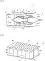
- FIG. 3 schematically illustrates a perspective view of an acoustic absorption cell 18 according to a first embodiment of the invention.
- the cell 18 comprises an acoustically opaque bottom wall 180, an acoustically porous inlet wall 181, and a cylindrical enclosure 185 with a hexagonal base extending between the bottom wall 180 and the inlet wall 181.
- the bottom wall 180 is formed by the reflective layer 14 of the acoustic treatment panel 10, while the entrance wall 181 is formed by the entrance layer 16 of the acoustic treatment panel 10.
- the cylinder formed by the enclosure 185 defines an axial direction D A corresponding to the direction of the generators of the cylinder. Furthermore, depending on the embodiment, the base of the cylinder formed by the enclosure 185 may have a shape other than hexagonal. The base may be triangular, or quadrilateral, or circular or polygonal for example.
- the enclosure 185 comprises a first axial end 1850 secured to the bottom wall 180, and a second axial end 1855 secured to the inlet wall 181.
- Each cell 18 of the acoustic treatment panel 10 further comprises two acoustic horns 30 and 40 inside the enclosure 185.
- the first acoustic horn 30 extends in the axial direction D A , between a first opening 31 and a second opening 32, the second opening 32 being smaller than the first opening 31.
- the second acoustic horn 40 extends in the axial direction D A between a first opening 41 and a second opening 42, the second opening 42 being smaller than the first opening 41.
- the first pavilion 30 and the second pavilion 40 are aligned along the axial direction D A . More particularly, the first orifice 31 of the first pavilion 30 is opposite the inlet wall 181, the second orifice 32 of the first pavilion 30 and the first orifice 41 of the second pavilion 40 are opposite each other, or even in the same plane, and the second orifice 42 of the second pavilion 40 is opposite the bottom wall 180.
- FIG. 4 schematically represents a sectional view of a plurality of acoustic absorption cells 18 according to the first embodiment of the invention.
- each cell comprises a section having a first equivalent diameter D and height H, the height H being measured in the axial direction D A , and the first equivalent diameter D being measured in the plane in which the inlet wall 181 extends, and corresponding to the diameter of the circle circumscribed at the base of the cylinder formed by the enclosure 185.
- the first orifice 31 of the first pavilion 30 and the first orifice 41 of the second pavilion 40 each have an equivalent diameter equal to the first equivalent diameter D of the cell 18.
- the second orifice 32 of the first pavilion 30 and the second orifice 42 of the second pavilion 40 have the same equivalent diameter which is equal to a second equivalent diameter d.
- the first pavilion 30 has a length equal to the length of the second pavilion 40.
- the length L of each of the two pavilions 30 and 40 is measured in the same direction as the height H of the cell 18, in this case the axial direction D A .
- the first opening 31 of the first pavilion 30 extends in a plane parallel to the first opening 41 of the second pavilion 40. From its first opening 31, the first pavilion 30 extends in a direction forming a first opening angle ⁇ 1 . Similarly, from its first opening 41, the second pavilion 40 extends in a direction forming a second opening angle ⁇ 2 .
- the first opening angle ⁇ 1 and the second opening angle ⁇ 2 are equal and are between 60° and 90°
- the ratio between the first equivalent diameter D and the second equivalent diameter d varies between 2 and 100.
- the ratio between the length of a pavilion 30 or 40 and the height H of the cell 18 varies between 0.2 and 0.6.
- an acoustic treatment panel 10 comprising cells 18 according to the first embodiment illustrated in the Figures 3 and 4 with a height H of 80 mm, a first equivalent diameter D of 19 mm, a length L of the horn of 35 mm, and a second equivalent diameter d of 6 mm, can make it possible to obtain two attenuation peaks centered approximately around 300 Hz and 750 Hz as illustrated in the Figure 5 .
- FIG. 5 is a graphical representation of the absorption coefficient as a function of the frequency of the sound wave in Hertz in a first case of an acoustic treatment cell with a single horn inside the enclosure, and in a second case of an acoustic absorption cell comprising two horns inside the enclosure according to the first embodiment of the invention.
- the first pavilion 30 comprises a portion having a continuous non-straight slope extending from its first orifice 31
- the second pavilion 40 comprises a portion having a continuous non-straight slope extending from its first orifice 41.
- the acoustic treatment panel 10 may comprise for each cell an internal septum formed by a porous internal wall 183 extending inside the enclosure 185 and over the first orifice 41 of the second horn 40.
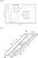
- FIG. 6 schematically illustrated is a perspective view of an acoustic absorption cell 18 according to a second embodiment of the invention.
- the second embodiment illustrated on the Figure 6 differs from the first embodiment illustrated on the Figures 3 and 4 in that the axial direction D A along which the generatrices of the cylinder formed by the enclosure 185 extend, is not orthogonal to the planes in which the bottom wall 180 and the inlet wall 181 extend respectively.
- the axial direction D A in which the walls 185 extend forms an angle of inclination ⁇ with the inlet 181 and bottom 180 walls, the inlet wall 181 and the bottom wall 180 extending parallel to each other.
- the inclination angle ⁇ varies between 0° and 60°. This angle makes it possible to increase the volume of the cavity inside the enclosure without increasing the distance separating the inlet wall 181 and the bottom wall 180, this distance being measured in a direction orthogonal to the planes in which the bottom and inlet walls extend.
- the second embodiment differs from the first embodiment in that the first orifices 31 and 41 and the second orifices 32 and 42 of the first and second pavilions 30 and 40 extend in planes not parallel to the planes in which the inlet wall 181 and the bottom wall 180 extend.
- first horn 30 and the second horn 40 may comprise surfaces having a non-zero roughness to increase viscoelastic friction and thus increase acoustic absorption.
- FIG. 7 schematically represents a sectional view of a plurality of acoustic absorption cells 18 according to the third embodiment of the invention.
- the third embodiment illustrated on the Figure 7 differs from the first embodiment illustrated in the Figure 4 in that its acoustic cells 18 do not include a porous internal wall (or septum) 183 between the two pavilions, and in that, for each cell 18, the first pavilion 30 is partially inserted into the second pavilion 40.
- the second orifice 32 of the first pavilion 30 is thus arranged, in the axial direction D A between the first orifice 41 of the second pavilion 40 and the second orifice 42 of the second pavilion 40.
- This third embodiment illustrated on the Figure 7 allows for a more compact acoustic treatment panel than the panel according to the first embodiment illustrated in the Figure 4 .
- FIG 8 schematically represents a sectional view of a plurality of acoustic absorption cells 18 according to the fourth embodiment of the invention.
- each acoustic cell 18 comprises at least one third horn 50 extending in the axial direction D A between a first orifice 51 and a second orifice 52, and in that the first horn 30 and the second horn 40 of each cell 18 are juxtaposed next to each other in two directions parallel to the axial direction D A and open via their respective second orifice 32 and 42 onto the first orifice 51 of the third horn 50, the second orifice 52 of the third horn 50 being arranged opposite the bottom wall 180.
- more than two pavilions, juxtaposed to each other or in the same direction, can open into the same pavilion arranged between the back wall 180 and said three or more pavilions.
- FIG. 9 schematically represents a sectional view of a plurality of acoustic absorption cells 18 according to the fifth embodiment of the invention.
- the acoustic cells 18 of the fifth embodiment illustrated in the Figure 9 differ from the acoustic cells illustrated on the Figure 6 in that the first and second orifices 31 and 32, and 41 and 42, of each pavilion 30 and 40 extend parallel to the inlet wall 181 and to the bottom wall 180.
- the invention thus makes it possible to provide an acoustic absorption cell for the absorption of low-frequency sound waves with a reduced cavity height and whose processing frequency range can be modulated as required.
Landscapes
- Engineering & Computer Science (AREA)
- Chemical & Material Sciences (AREA)
- Combustion & Propulsion (AREA)
- Mechanical Engineering (AREA)
- General Engineering & Computer Science (AREA)
- Aviation & Aerospace Engineering (AREA)
- Physics & Mathematics (AREA)
- Acoustics & Sound (AREA)
- Multimedia (AREA)
- Soundproofing, Sound Blocking, And Sound Damping (AREA)
Claims (13)
- Schallabsorptionszelle (18), umfassend eine schallundurchlässige Bodenwand (180), eine schallporöse Eingangswand (181), ein Gehäuse (185), das sich in einer axialen Richtung (DA) zwischen einem ersten axialen Ende (1850), das an der Bodenwand (180) befestigt ist, und einem zweiten axialen Ende (1855), das an der Eingangswand (181) befestigt ist, erstreckt, und ein erstes Schallhorn (30), das sich innerhalb des Gehäuses (185) zwischen einer ersten Öffnung (31) des ersten Horns (30) und einer zweiten Öffnung (32) des ersten Horns (30), die kleiner als die erste Öffnung (31) des ersten Horns (30) ist, erstreckt, wobei die erste Öffnung (31) der Eingangswand (181) zugewandt ist,dadurch gekennzeichnet, dass sie zumindest ein zweites Horn (40, 50) umfasst, das sich innerhalb des Gehäuses (185) zwischen einer ersten Öffnung (41, 51) des zweiten Horns (40, 50) und einer zweiten Öffnung (42, 52) des zweiten Horns (40, 50), die kleiner als die erste Öffnung (41, 51) des zweiten Horns (40, 50) ist, erstreckt, wobei die zweite Öffnung (42, 52) des zweiten Horns (40, 50) der Bodenwand (180) zugewandt angeordnet ist, undentweder die erste Öffnung (41, 51) des zweiten Horns (40, 50) der zweiten Öffnung (32) des ersten Horns (30) zugewandt angeordnet ist oder das erste Horn (30) und das zweite Horn (40) koaxial zu dem ersten Horn (30) sind, das zumindest teilweise in dem zweiten Horn (40) verschachtelt ist.
- Schallabsorptionszelle (18) nach Anspruch 1, wobei sich das Gehäuse (185) zwischen der Bodenwand (180) und der Eingangswand (181) erstreckt und dabei einen Neigungswinkel (β) ungleich null und nicht orthogonal zu der Eingangswand (181) einerseits und zu der Bodenwand (180) andererseits bildet.
- Schallabsorptionszelle (18) nach einem der Ansprüche 1 oder 2, wobei der Querschnitt der zweiten Öffnung (32) des ersten Horns (30) gleich dem Querschnitt der zweiten Öffnung (42) des zweiten Horns (40) ist und das Verhältnis zwischen dem Querschnitt des Gehäuses (185) an seinem zweiten Ende (1855) und dem Querschnitt der zweiten Öffnung des ersten Horns (30) zwischen 2 und 100 liegt.
- Schallabsorptionszelle (18) nach einem der Ansprüche 1 bis 3, wobei der Abstand zwischen der ersten Öffnung (31) und der zweiten Öffnung (32) des ersten Horns (30) in der axialen Richtung (DA) gleich dem Abstand zwischen der ersten Öffnung (41) und der zweiten Öffnung (42) des zweiten Horns (40) in der axialen Richtung (DA) ist und das Verhältnis zwischen dem Abstand zwischen der ersten Öffnung (31) und der zweiten Öffnung (32) des ersten Horns (30) in der axialen Richtung (DA) und der Höhe des Gehäuses (185), gemessen in der axialen Richtung (DA), zwischen seinem ersten Ende (1850) und seinem zweiten Ende (1855) zwischen 0,2 und 0,6 liegt.
- Schallabsorptionszelle (18) nach einem der Ansprüche 1 bis 4, wobei das erste Horn (30) an seiner ersten Öffnung (31) einen ersten Öffnungswinkel (α1) mit einer Ebene parallel zu der Eingangswand (181) der Zelle (18) bildet und das zweite Horn (40) an seiner ersten Öffnung (41) einen zweiten Öffnungswinkel (α2) mit einer Ebene parallel zu der Eingangswand (181) der Zelle (18) bildet.
- Schallabsorptionszelle (18) nach Anspruch 5, wobei der zweite Öffnungswinkel (α2) identisch mit dem ersten Öffnungswinkel (α1) ist.
- Schallabsorptionszelle (18) nach einem der Ansprüche 1 bis 6, wobei das erste Horn (30) und das zweite Horn (40) identische Form und Abmessungen aufweisen, wobei das erste Horn (30) und das zweite Horn (40) jeweils einen zylindrischen Abschnitt mit einem Querschnitt gleich dem Querschnitt ihrer zweiten Öffnung (32, 42) umfassen, wobei das Verhältnis zwischen der Länge des zylindrischen Abschnittes in der axialen Richtung (DA) und der Länge des Horns in der axialen Richtung (DA) kleiner oder gleich 0,8 ist.
- Schallabsorptionszelle (18) nach einem der Ansprüche 1 bis 7, umfassend zumindest eine poröse Innenwand (183), die sich innerhalb des Gehäuses (185) und an der ersten Öffnung (31, 41, 51) von einem der Hörner (30, 40, 50) erstreckt.
- Schallabsorptionszelle (18) nach Anspruch 8, wobei die Innenwand (183) parallel zu der Eingangswand (181) ist.
- Schallabsorptionszelle (18) nach einem der Ansprüche 1 bis 9, wobei das erste Horn (30) einen Abschnitt mit einer kontinuierlichen, nicht geraden Neigung umfasst, der sich von seiner ersten Öffnung (31) erstreckt, und das zweite Horn (40) einen Abschnitt mit einer kontinuierlichen, nicht geraden Neigung umfasst, der sich von seiner ersten Öffnung (41) erstreckt.
- Schallbehandlungsplatte (10), die dazu bestimmt ist, an zumindest einer Wand eines Flugzeugs in Kontakt mit einem Fluidstrom (F, FP, FS) angeordnet zu sein, wobei die Platte (10) mehrere Schallabsorptionszellen (18) nach einem der Ansprüche 1 bis 10 umfasst.
- Turbomaschine (1), die dazu bestimmt ist, an einem Flugzeug montiert zu sein, wobei die Turbomaschine (1) zumindest eine Schallbehandlungsplatte (10) nach Anspruch 11 umfasst.
- Flugzeug, umfassend zumindest eine Turbomaschine (1) nach Anspruch 12.
Applications Claiming Priority (2)
| Application Number | Priority Date | Filing Date | Title |
|---|---|---|---|
| FR2013230A FR3117658B1 (fr) | 2020-12-15 | 2020-12-15 | Panneau de traitement acoustique à encombrement réduit pour turboréacteur |
| PCT/FR2021/052328 WO2022129778A1 (fr) | 2020-12-15 | 2021-12-14 | Panneau de traitement acoustique à encombrement réduit pour turboréacteur |
Publications (2)
| Publication Number | Publication Date |
|---|---|
| EP4264594A1 EP4264594A1 (de) | 2023-10-25 |
| EP4264594B1 true EP4264594B1 (de) | 2025-05-07 |
Family
ID=74347416
Family Applications (1)
| Application Number | Title | Priority Date | Filing Date |
|---|---|---|---|
| EP21851827.2A Active EP4264594B1 (de) | 2020-12-15 | 2021-12-14 | Schallbehandlungsplatte mit reduzierter volumenleistung für ein turbostrahltriebwerk |
Country Status (5)
| Country | Link |
|---|---|
| US (1) | US12337986B2 (de) |
| EP (1) | EP4264594B1 (de) |
| CN (1) | CN116806353A (de) |
| FR (1) | FR3117658B1 (de) |
| WO (1) | WO2022129778A1 (de) |
Families Citing this family (7)
| Publication number | Priority date | Publication date | Assignee | Title |
|---|---|---|---|---|
| WO2020065705A1 (ja) * | 2018-09-25 | 2020-04-02 | 河西工業株式会社 | 自動車用遮音パネル |
| CA3084631A1 (fr) * | 2020-06-23 | 2021-12-23 | Safran | Panneau acoustique et procede de fabrication associe |
| US11715450B2 (en) * | 2020-12-22 | 2023-08-01 | Rohr, Inc. | Acoustic panel core cell with funnel shaped septum |
| US12548540B2 (en) * | 2021-03-29 | 2026-02-10 | Bae Systems Plc | Acoustic absorbing structures |
| US12110844B2 (en) | 2022-11-15 | 2024-10-08 | Rohr, Inc. | Zoned liner exhaust with buried N-core |
| CN117211963B (zh) * | 2023-08-25 | 2026-02-06 | 武汉理工大学 | 一种爆轰波高效起爆装置 |
| FR3164826A1 (fr) * | 2024-07-19 | 2026-01-23 | Airbus Operations (S.A.S.) | Ensemble constituant un matériau acoustiquement absorbant |
Family Cites Families (8)
| Publication number | Priority date | Publication date | Assignee | Title |
|---|---|---|---|---|
| US3821999A (en) * | 1972-09-05 | 1974-07-02 | Mc Donnell Douglas Corp | Acoustic liner |
| US4743740A (en) * | 1985-10-07 | 1988-05-10 | Rohr Industries, Inc. | Buried element deicer |
| US6619913B2 (en) * | 2002-02-15 | 2003-09-16 | General Electric Company | Fan casing acoustic treatment |
| DE102004012929B3 (de) * | 2004-03-17 | 2005-04-21 | Dornier Gmbh | Anordnung zur Lärmreduzierung in Turbofantriebwerken |
| DE102011120979A1 (de) * | 2011-12-13 | 2013-06-13 | Rolls-Royce Deutschland Ltd & Co Kg | Akustischer Absorber |
| US10851713B2 (en) * | 2017-08-29 | 2020-12-01 | Mra Systems, Llc. | Acoustic liner having internal structure |
| FR3070529B1 (fr) | 2017-08-31 | 2019-12-20 | Safran Nacelles | Panneau acoustique a resonateurs pour volume reduit |
| FR3085783B1 (fr) * | 2018-09-10 | 2021-04-23 | Safran Aircraft Engines | Panneau de traitement acoustique pour turboreacteur |
-
2020
- 2020-12-15 FR FR2013230A patent/FR3117658B1/fr active Active
-
2021
- 2021-12-14 US US18/257,810 patent/US12337986B2/en active Active
- 2021-12-14 WO PCT/FR2021/052328 patent/WO2022129778A1/fr not_active Ceased
- 2021-12-14 EP EP21851827.2A patent/EP4264594B1/de active Active
- 2021-12-14 CN CN202180091536.7A patent/CN116806353A/zh active Pending
Also Published As
| Publication number | Publication date |
|---|---|
| FR3117658B1 (fr) | 2023-08-11 |
| WO2022129778A1 (fr) | 2022-06-23 |
| FR3117658A1 (fr) | 2022-06-17 |
| US12337986B2 (en) | 2025-06-24 |
| CN116806353A (zh) | 2023-09-26 |
| EP4264594A1 (de) | 2023-10-25 |
| US20240101264A1 (en) | 2024-03-28 |
Similar Documents
| Publication | Publication Date | Title |
|---|---|---|
| EP3850616B1 (de) | Schalldämmplatte für ein turbostrahltriebwerk | |
| EP4264594B1 (de) | Schallbehandlungsplatte mit reduzierter volumenleistung für ein turbostrahltriebwerk | |
| EP3963192B1 (de) | Integration eines lüfterflatterdämpfers in ein motorgehäuse | |
| CA2292821C (fr) | Dispositif d'echappement multicanal de turbomachine traite acoustiquement | |
| EP3963199B1 (de) | Schubumkehrerkaskade mit schallbehandlung | |
| EP3489487A1 (de) | Schalldämmplatte für luftfahrzeug | |
| WO2017021628A1 (fr) | Structure d'atténuation acoustique à multiples degrés d'atténuation pour ensemble propulsif d'aéronef | |
| FR3028886B1 (fr) | Organe de reduction de bruit de soufflante de turboreacteur | |
| EP3963200B1 (de) | Schubumkehrerkaskade mit schallbehandlung | |
| CA3135599A1 (fr) | Grille d'inverseur de poussee incluant un traitement acoustique | |
| EP3775524B1 (de) | Schalldämmplatte für ein turbostrahltriebwerk | |
| EP4352722B1 (de) | Akustische behandlungsvorrichtung für eine flugzeugantriebsanordnung und verfahren zu ihrer herstellung | |
| FR3049571B1 (fr) | Aile d'aeronef a traitement acoustique amelioree | |
| CA2869623A1 (fr) | Panneau mince d'absorption d'ondes acoustiques emises par un turboreacteur de nacelle d'aeronef, et nacelle equipee d'un tel panneau | |
| EP2435685B1 (de) | Fluggasturbine mit schalldämpfer im abgasendstück | |
| EP4066235B1 (de) | Resonanz-patch und akustische behandlungszelle mit einem solchen patch | |
| EP3853464B1 (de) | Verfahren zur herstellung eines trägers und zur akustischen verwaltung auf einem turbinentriebwerk oder einer gondel | |
| WO2024089342A1 (fr) | Procede de formation d'une structure d'attenuation acoustique dotee de cellules en s | |
| EP4710325A1 (de) | Schalldämpfungsstruktur mit s-förmigen zellen mit drainierten barrieren und verfahren zur herstellung davon |
Legal Events
| Date | Code | Title | Description |
|---|---|---|---|
| STAA | Information on the status of an ep patent application or granted ep patent |
Free format text: STATUS: UNKNOWN |
|
| STAA | Information on the status of an ep patent application or granted ep patent |
Free format text: STATUS: THE INTERNATIONAL PUBLICATION HAS BEEN MADE |
|
| PUAI | Public reference made under article 153(3) epc to a published international application that has entered the european phase |
Free format text: ORIGINAL CODE: 0009012 |
|
| STAA | Information on the status of an ep patent application or granted ep patent |
Free format text: STATUS: REQUEST FOR EXAMINATION WAS MADE |
|
| 17P | Request for examination filed |
Effective date: 20230620 |
|
| AK | Designated contracting states |
Kind code of ref document: A1 Designated state(s): AL AT BE BG CH CY CZ DE DK EE ES FI FR GB GR HR HU IE IS IT LI LT LU LV MC MK MT NL NO PL PT RO RS SE SI SK SM TR |
|
| DAV | Request for validation of the european patent (deleted) | ||
| DAX | Request for extension of the european patent (deleted) | ||
| GRAP | Despatch of communication of intention to grant a patent |
Free format text: ORIGINAL CODE: EPIDOSNIGR1 |
|
| STAA | Information on the status of an ep patent application or granted ep patent |
Free format text: STATUS: GRANT OF PATENT IS INTENDED |
|
| INTG | Intention to grant announced |
Effective date: 20240822 |
|
| GRAJ | Information related to disapproval of communication of intention to grant by the applicant or resumption of examination proceedings by the epo deleted |
Free format text: ORIGINAL CODE: EPIDOSDIGR1 |
|
| STAA | Information on the status of an ep patent application or granted ep patent |
Free format text: STATUS: REQUEST FOR EXAMINATION WAS MADE |
|
| GRAS | Grant fee paid |
Free format text: ORIGINAL CODE: EPIDOSNIGR3 |
|
| STAA | Information on the status of an ep patent application or granted ep patent |
Free format text: STATUS: GRANT OF PATENT IS INTENDED |
|
| GRAP | Despatch of communication of intention to grant a patent |
Free format text: ORIGINAL CODE: EPIDOSNIGR1 |
|
| INTC | Intention to grant announced (deleted) | ||
| INTG | Intention to grant announced |
Effective date: 20241219 |
|
| GRAA | (expected) grant |
Free format text: ORIGINAL CODE: 0009210 |
|
| STAA | Information on the status of an ep patent application or granted ep patent |
Free format text: STATUS: THE PATENT HAS BEEN GRANTED |
|
| AK | Designated contracting states |
Kind code of ref document: B1 Designated state(s): AL AT BE BG CH CY CZ DE DK EE ES FI FR GB GR HR HU IE IS IT LI LT LU LV MC MK MT NL NO PL PT RO RS SE SI SK SM TR |
|
| REG | Reference to a national code |
Ref country code: GB Ref legal event code: FG4D Free format text: NOT ENGLISH |
|
| REG | Reference to a national code |
Ref country code: CH Ref legal event code: EP |
|
| REG | Reference to a national code |
Ref country code: DE Ref legal event code: R096 Ref document number: 602021030587 Country of ref document: DE |
|
| REG | Reference to a national code |
Ref country code: IE Ref legal event code: FG4D Free format text: LANGUAGE OF EP DOCUMENT: FRENCH |
|
| REG | Reference to a national code |
Ref country code: NL Ref legal event code: MP Effective date: 20250507 |
|
| PG25 | Lapsed in a contracting state [announced via postgrant information from national office to epo] |
Ref country code: PT Free format text: LAPSE BECAUSE OF FAILURE TO SUBMIT A TRANSLATION OF THE DESCRIPTION OR TO PAY THE FEE WITHIN THE PRESCRIBED TIME-LIMIT Effective date: 20250908 Ref country code: ES Free format text: LAPSE BECAUSE OF FAILURE TO SUBMIT A TRANSLATION OF THE DESCRIPTION OR TO PAY THE FEE WITHIN THE PRESCRIBED TIME-LIMIT Effective date: 20250507 Ref country code: FI Free format text: LAPSE BECAUSE OF FAILURE TO SUBMIT A TRANSLATION OF THE DESCRIPTION OR TO PAY THE FEE WITHIN THE PRESCRIBED TIME-LIMIT Effective date: 20250507 |
|
| REG | Reference to a national code |
Ref country code: LT Ref legal event code: MG9D |
|
| PG25 | Lapsed in a contracting state [announced via postgrant information from national office to epo] |
Ref country code: GR Free format text: LAPSE BECAUSE OF FAILURE TO SUBMIT A TRANSLATION OF THE DESCRIPTION OR TO PAY THE FEE WITHIN THE PRESCRIBED TIME-LIMIT Effective date: 20250808 Ref country code: NO Free format text: LAPSE BECAUSE OF FAILURE TO SUBMIT A TRANSLATION OF THE DESCRIPTION OR TO PAY THE FEE WITHIN THE PRESCRIBED TIME-LIMIT Effective date: 20250807 |
|
| PG25 | Lapsed in a contracting state [announced via postgrant information from national office to epo] |
Ref country code: NL Free format text: LAPSE BECAUSE OF FAILURE TO SUBMIT A TRANSLATION OF THE DESCRIPTION OR TO PAY THE FEE WITHIN THE PRESCRIBED TIME-LIMIT Effective date: 20250507 Ref country code: PL Free format text: LAPSE BECAUSE OF FAILURE TO SUBMIT A TRANSLATION OF THE DESCRIPTION OR TO PAY THE FEE WITHIN THE PRESCRIBED TIME-LIMIT Effective date: 20250507 |
|
| REG | Reference to a national code |
Ref country code: AT Ref legal event code: MK05 Ref document number: 1793397 Country of ref document: AT Kind code of ref document: T Effective date: 20250507 |
|
| PG25 | Lapsed in a contracting state [announced via postgrant information from national office to epo] |
Ref country code: BG Free format text: LAPSE BECAUSE OF FAILURE TO SUBMIT A TRANSLATION OF THE DESCRIPTION OR TO PAY THE FEE WITHIN THE PRESCRIBED TIME-LIMIT Effective date: 20250507 |
|
| PG25 | Lapsed in a contracting state [announced via postgrant information from national office to epo] |
Ref country code: HR Free format text: LAPSE BECAUSE OF FAILURE TO SUBMIT A TRANSLATION OF THE DESCRIPTION OR TO PAY THE FEE WITHIN THE PRESCRIBED TIME-LIMIT Effective date: 20250507 |
|
| PG25 | Lapsed in a contracting state [announced via postgrant information from national office to epo] |
Ref country code: AT Free format text: LAPSE BECAUSE OF FAILURE TO SUBMIT A TRANSLATION OF THE DESCRIPTION OR TO PAY THE FEE WITHIN THE PRESCRIBED TIME-LIMIT Effective date: 20250507 |
|
| PG25 | Lapsed in a contracting state [announced via postgrant information from national office to epo] |
Ref country code: RS Free format text: LAPSE BECAUSE OF FAILURE TO SUBMIT A TRANSLATION OF THE DESCRIPTION OR TO PAY THE FEE WITHIN THE PRESCRIBED TIME-LIMIT Effective date: 20250807 |
|
| PG25 | Lapsed in a contracting state [announced via postgrant information from national office to epo] |
Ref country code: IS Free format text: LAPSE BECAUSE OF FAILURE TO SUBMIT A TRANSLATION OF THE DESCRIPTION OR TO PAY THE FEE WITHIN THE PRESCRIBED TIME-LIMIT Effective date: 20250907 |
|
| PG25 | Lapsed in a contracting state [announced via postgrant information from national office to epo] |
Ref country code: LV Free format text: LAPSE BECAUSE OF FAILURE TO SUBMIT A TRANSLATION OF THE DESCRIPTION OR TO PAY THE FEE WITHIN THE PRESCRIBED TIME-LIMIT Effective date: 20250507 |
|
| PGFP | Annual fee paid to national office [announced via postgrant information from national office to epo] |
Ref country code: GB Payment date: 20251229 Year of fee payment: 5 |
|
| PG25 | Lapsed in a contracting state [announced via postgrant information from national office to epo] |
Ref country code: SM Free format text: LAPSE BECAUSE OF FAILURE TO SUBMIT A TRANSLATION OF THE DESCRIPTION OR TO PAY THE FEE WITHIN THE PRESCRIBED TIME-LIMIT Effective date: 20250507 Ref country code: DK Free format text: LAPSE BECAUSE OF FAILURE TO SUBMIT A TRANSLATION OF THE DESCRIPTION OR TO PAY THE FEE WITHIN THE PRESCRIBED TIME-LIMIT Effective date: 20250507 |
|
| PGFP | Annual fee paid to national office [announced via postgrant information from national office to epo] |
Ref country code: FR Payment date: 20251222 Year of fee payment: 5 |
|
| PG25 | Lapsed in a contracting state [announced via postgrant information from national office to epo] |
Ref country code: CZ Free format text: LAPSE BECAUSE OF FAILURE TO SUBMIT A TRANSLATION OF THE DESCRIPTION OR TO PAY THE FEE WITHIN THE PRESCRIBED TIME-LIMIT Effective date: 20250507 |
|
| PG25 | Lapsed in a contracting state [announced via postgrant information from national office to epo] |
Ref country code: EE Free format text: LAPSE BECAUSE OF FAILURE TO SUBMIT A TRANSLATION OF THE DESCRIPTION OR TO PAY THE FEE WITHIN THE PRESCRIBED TIME-LIMIT Effective date: 20250507 |
|
| PG25 | Lapsed in a contracting state [announced via postgrant information from national office to epo] |
Ref country code: SK Free format text: LAPSE BECAUSE OF FAILURE TO SUBMIT A TRANSLATION OF THE DESCRIPTION OR TO PAY THE FEE WITHIN THE PRESCRIBED TIME-LIMIT Effective date: 20250507 |
|
| PG25 | Lapsed in a contracting state [announced via postgrant information from national office to epo] |
Ref country code: IT Free format text: LAPSE BECAUSE OF FAILURE TO SUBMIT A TRANSLATION OF THE DESCRIPTION OR TO PAY THE FEE WITHIN THE PRESCRIBED TIME-LIMIT Effective date: 20250507 |
|
| REG | Reference to a national code |
Ref country code: DE Ref legal event code: R097 Ref document number: 602021030587 Country of ref document: DE |
|
| PG25 | Lapsed in a contracting state [announced via postgrant information from national office to epo] |
Ref country code: RO Free format text: LAPSE BECAUSE OF FAILURE TO SUBMIT A TRANSLATION OF THE DESCRIPTION OR TO PAY THE FEE WITHIN THE PRESCRIBED TIME-LIMIT Effective date: 20250507 |
|
| PLBE | No opposition filed within time limit |
Free format text: ORIGINAL CODE: 0009261 |
|
| STAA | Information on the status of an ep patent application or granted ep patent |
Free format text: STATUS: NO OPPOSITION FILED WITHIN TIME LIMIT |
|
| REG | Reference to a national code |
Ref country code: CH Ref legal event code: L10 Free format text: ST27 STATUS EVENT CODE: U-0-0-L10-L00 (AS PROVIDED BY THE NATIONAL OFFICE) Effective date: 20260318 |
|
| PGFP | Annual fee paid to national office [announced via postgrant information from national office to epo] |
Ref country code: DE Payment date: 20251222 Year of fee payment: 5 |
|
| 26N | No opposition filed |
Effective date: 20260210 |