EP3853464B1 - Verfahren zur herstellung eines trägers und zur akustischen verwaltung auf einem turbinentriebwerk oder einer gondel - Google Patents
Verfahren zur herstellung eines trägers und zur akustischen verwaltung auf einem turbinentriebwerk oder einer gondel Download PDFInfo
- Publication number
- EP3853464B1 EP3853464B1 EP19791321.3A EP19791321A EP3853464B1 EP 3853464 B1 EP3853464 B1 EP 3853464B1 EP 19791321 A EP19791321 A EP 19791321A EP 3853464 B1 EP3853464 B1 EP 3853464B1
- Authority
- EP
- European Patent Office
- Prior art keywords
- panel
- recess
- support
- nacelle
- acoustic
- Prior art date
- Legal status (The legal status is an assumption and is not a legal conclusion. Google has not performed a legal analysis and makes no representation as to the accuracy of the status listed.)
- Active
Links
Images


Classifications
-
- F—MECHANICAL ENGINEERING; LIGHTING; HEATING; WEAPONS; BLASTING
- F02—COMBUSTION ENGINES; HOT-GAS OR COMBUSTION-PRODUCT ENGINE PLANTS
- F02K—JET-PROPULSION PLANTS
- F02K1/00—Plants characterised by the form or arrangement of the jet pipe or nozzle; Jet pipes or nozzles peculiar thereto
- F02K1/78—Other construction of jet pipes
- F02K1/82—Jet pipe walls, e.g. liners
- F02K1/827—Sound absorbing structures or liners
-
- B—PERFORMING OPERATIONS; TRANSPORTING
- B64—AIRCRAFT; AVIATION; COSMONAUTICS
- B64D—EQUIPMENT FOR FITTING IN OR TO AIRCRAFT; FLIGHT SUITS; PARACHUTES; ARRANGEMENT OR MOUNTING OF POWER PLANTS OR PROPULSION TRANSMISSIONS IN AIRCRAFT
- B64D33/00—Arrangement in aircraft of power plant parts or auxiliaries not otherwise provided for
- B64D33/02—Arrangement in aircraft of power plant parts or auxiliaries not otherwise provided for of combustion air intakes
-
- F—MECHANICAL ENGINEERING; LIGHTING; HEATING; WEAPONS; BLASTING
- F02—COMBUSTION ENGINES; HOT-GAS OR COMBUSTION-PRODUCT ENGINE PLANTS
- F02C—GAS-TURBINE PLANTS; AIR INTAKES FOR JET-PROPULSION PLANTS; CONTROLLING FUEL SUPPLY IN AIR-BREATHING JET-PROPULSION PLANTS
- F02C7/00—Features, components parts, details or accessories, not provided for in, or of interest apart form groups F02C1/00 - F02C6/00; Air intakes for jet-propulsion plants
- F02C7/04—Air intakes for gas-turbine plants or jet-propulsion plants
- F02C7/045—Air intakes for gas-turbine plants or jet-propulsion plants having provisions for noise suppression
-
- F—MECHANICAL ENGINEERING; LIGHTING; HEATING; WEAPONS; BLASTING
- F02—COMBUSTION ENGINES; HOT-GAS OR COMBUSTION-PRODUCT ENGINE PLANTS
- F02C—GAS-TURBINE PLANTS; AIR INTAKES FOR JET-PROPULSION PLANTS; CONTROLLING FUEL SUPPLY IN AIR-BREATHING JET-PROPULSION PLANTS
- F02C7/00—Features, components parts, details or accessories, not provided for in, or of interest apart form groups F02C1/00 - F02C6/00; Air intakes for jet-propulsion plants
- F02C7/24—Heat or noise insulation
-
- B—PERFORMING OPERATIONS; TRANSPORTING
- B64—AIRCRAFT; AVIATION; COSMONAUTICS
- B64D—EQUIPMENT FOR FITTING IN OR TO AIRCRAFT; FLIGHT SUITS; PARACHUTES; ARRANGEMENT OR MOUNTING OF POWER PLANTS OR PROPULSION TRANSMISSIONS IN AIRCRAFT
- B64D33/00—Arrangement in aircraft of power plant parts or auxiliaries not otherwise provided for
- B64D33/02—Arrangement in aircraft of power plant parts or auxiliaries not otherwise provided for of combustion air intakes
- B64D2033/0206—Arrangement in aircraft of power plant parts or auxiliaries not otherwise provided for of combustion air intakes comprising noise reduction means, e.g. acoustic liners
-
- B—PERFORMING OPERATIONS; TRANSPORTING
- B64—AIRCRAFT; AVIATION; COSMONAUTICS
- B64D—EQUIPMENT FOR FITTING IN OR TO AIRCRAFT; FLIGHT SUITS; PARACHUTES; ARRANGEMENT OR MOUNTING OF POWER PLANTS OR PROPULSION TRANSMISSIONS IN AIRCRAFT
- B64D33/00—Arrangement in aircraft of power plant parts or auxiliaries not otherwise provided for
- B64D33/02—Arrangement in aircraft of power plant parts or auxiliaries not otherwise provided for of combustion air intakes
- B64D2033/0266—Arrangement in aircraft of power plant parts or auxiliaries not otherwise provided for of combustion air intakes specially adapted for particular type of power plants
- B64D2033/0273—Arrangement in aircraft of power plant parts or auxiliaries not otherwise provided for of combustion air intakes specially adapted for particular type of power plants for jet engines
-
- F—MECHANICAL ENGINEERING; LIGHTING; HEATING; WEAPONS; BLASTING
- F05—INDEXING SCHEMES RELATING TO ENGINES OR PUMPS IN VARIOUS SUBCLASSES OF CLASSES F01-F04
- F05D—INDEXING SCHEME FOR ASPECTS RELATING TO NON-POSITIVE-DISPLACEMENT MACHINES OR ENGINES, GAS-TURBINES OR JET-PROPULSION PLANTS
- F05D2230/00—Manufacture
- F05D2230/80—Repairing, retrofitting or upgrading methods
-
- F—MECHANICAL ENGINEERING; LIGHTING; HEATING; WEAPONS; BLASTING
- F05—INDEXING SCHEMES RELATING TO ENGINES OR PUMPS IN VARIOUS SUBCLASSES OF CLASSES F01-F04
- F05D—INDEXING SCHEME FOR ASPECTS RELATING TO NON-POSITIVE-DISPLACEMENT MACHINES OR ENGINES, GAS-TURBINES OR JET-PROPULSION PLANTS
- F05D2260/00—Function
- F05D2260/96—Preventing, counteracting or reducing vibration or noise
Definitions
- the present invention relates to the optimization of an acoustic compromise on aircraft engines.
- acoustic panels in aircraft turbomachines in particular aircraft engines, is, in part, justified by constraints associated with flight limitation policies at airports. These constraints are expressed in particular in terms of noise charges (financial charges applied to airlines each time an airport is used). These noise charges are at the discretion of each airport, which determines, in consultation with users, the charge structure to be applied locally.
- EP3372805 , US 2014/321999 , FR 2989814 , FR 3039517 disclose a method for preparing a zone of a support and for acoustic management and an acoustic management assembly conforming to the preamble of claim 1.
- the aerodynamic penalty associated with a depth which can be materialized by a difference in vein section, can reach relatively low levels (acceptable with regard to a balanced compromise between performance and acoustic).
- the issue of bulk lies particularly in the thickness of the panel. On a classic panel, the thickness is conditioned by the tuning frequency (that to be attenuated), therefore the wavelength of the acoustic signal. The lower the frequency, the higher the wavelength, and the thicker the panel must be.
- Some solutions provide so-called “folded” – or (re)folded – or “inclined” cavities which then extend in several directions (radial + axial for example), so as to minimize the thickness of the panel.
- porous materials it is rather the internal structure of the material which adjusts the tuning frequency, making it possible to process low frequencies in reduced dimensions compared to the classic honeycomb type panel.
- claim 2 defines a preferred solution to the problem posed above, in such an acoustic management assembly.
- the figures 1 and 2 therefore schematize two possible cases in which the invention can be applied.
- a nacelle 1 of a dual-flow aircraft turbojet 3 is shown schematically.
- the nacelle 1 which therefore constitutes an assembly of support and covers for the aircraft turbomachine concerned and which ensures its connection with the fuselage of the aircraft, conventionally comprises an external structure 1a comprising an upstream section 5 (AM) forming an inlet air, a middle section 7 and a downstream section 9 (AV) which can incorporate thrust reversal means.
- the upstream section 5 or the middle section 7 has an internal wall formed by a casing 17 of a fan 11 of the turbojet.
- the fan casing 17 can define the “external annular casing” also mentioned.
- the nacelle 1 also comprises an internal structure 1b comprising (at least) a fairing 15 of the engine 19 of the turbojet.
- the external structure 1a of the nacelle 1 defines, with the internal structure 1b, an annular air stream 21, often referred to as a “secondary or cold air stream”, as opposed to the hot air generated by the engine 19, where a so-called primary vein passes.
- the fan 11 comprises a propeller comprising a plurality of blades 23, mounted around the axis of rotation of flow 29 (OGV) making it possible to straighten the flow of cold air generated by the fan 11.
- Structural arms 27 radially connect the nacelle 1 to the internal structure 1b.
- IGVs may be present in the form of a grid of blades located in the primary flow 45a, upstream of the low pressure compressor.
- the hub 25 is linked upstream to an air inlet cone 26 of the turbojet.
- the downstream section 9 comprises a fixed internal structure 31 (IFS) surrounding the upstream part of the turbojet 3, a fixed external structure 35 (OFS) and a movable cover 37 which may include thrust reversal means.
- IFS fixed internal structure 31
- OFS fixed external structure 35
- movable cover 37 which may include thrust reversal means.
- a mast of suspension (not shown) supports the turbojet 3 and the nacelle 1.
- the nacelle 1b ends downstream with a profiled ejection nozzle 39.
- the external and internal surfaces of the primary flow (respectively defined by the external primary nozzle sleeve - or "primary nozzle sleeve - 41 and the plug 43 - or “primary nozzle plug; in French: "bout” or "internal tip of primary nozzle ) define between them the terminal downstream part, outlet, of the channel or vein 45a for the flow of the primary air flow 45, called hot, leaving the turbojet.
- a nacelle 10 of another aircraft turbomachine is shown schematically, here an aircraft turboprop 12.
- Nacelle 10 is also called fairing. It comprises a structure 30, external (in the sense that it surrounds the vein 28a), comprising at least one annular casing, here three 33a, 33b, 33c, themselves therefore external, around the axis X.
- the turboprop 12 comprises from upstream to downstream, along the axis of rotation along which there is a compressor 20, a combustion chamber 22 and a turbine 24, downstream of which the gases exit through an exhaust outlet 26.
- the nacelle 10 extends around the axis from the compressor 20 to the downstream end of the exhaust outlet 26.
- the present invention aims to seek to refine the ability to adapt the level of noise reduction technology of such a surface according to the needs of the users: depending on these needs, reducing the noise is useful or not, necessary or not, required or not. You need to be able to adapt to circumstances.
- One aspect of the invention is therefore also to be able to substitute a panel 32 with non-acoustic characteristics for a panel 30 with acoustic characteristics, and vice versa.
- the two panels 30,32 could be identical, in terms of overall dimensions (lengths, widths, thicknesses, etc.) since they are both designed to be adapted to be placed in a recess 34 formed hollowly relative to a general surrounding surface 36 of a support 38 belonging to the turbomachine 3.12 or to its nacelle 1.10.
- the support 38 can be a frame element and/or comprising beams and itself panels, in particular to define the exterior surfaces 30a, 32a, 34a.
- the exterior surfaces 30a, 32a, 34a may have so-called aerodynamic characteristics, as may preferably be the general surrounding surface 36.
- the general surrounding surface 36 is the surface which is adjacent to the recess 34. It limits or delimits it.
- the exterior surfaces 30a, 32a, 34a must be in contact with the moving air (21,28 or 45) and being located in a gas stream (air or air/fuel mixture), they will be limiting surfaces in such a vein. In aircraft, these surfaces are well known. We know how to identify them and achieve them.
- the exterior surfaces 30a, 32a, 34a will typically be concave (radially external vein limits), or convex (radially internal vein limits). Given that the diffusion of noise must be managed a priori in all directions, placed in a said vein, the general surrounding surface 36 could typically be closed (present a perimeter), extend around the axis around it, or parallel to this axis.
- the panels 30,32 are a priori interchangeable and may or may not be present in the recess 34 provided to receive them alternately, in a removable manner
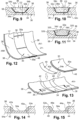
- the respective dimensions of the recess 34 (length L1, width l1, depth E1, figure 5 ) and those corresponding to panels 30.32 (length L2, width l2, thickness E2, Figure 4 ) will preferably be identical, except for installation/removal clearances, and excluding the hypothesis of the use of removable aerodynamic smoothing elements, or joints, 40-46; see figures 13-15 .
- the discontinuities of the surface 36 of the support can cause relatively significant aerodynamic disturbances.
- the shapes of the other solutions above allow a progressive transition via possible changes in the radii of the side walls concerned, such as 52c/54c; 52d/54d, this in particular at the level of the axial edges/axial side walls of the surface dedicated to the removable fixing of the panel 30 or 32 considered. It is also these axial edges (upstream and downstream) that the sections of the different figures (9 to 11 notably).
- the other edges/side walls can have the same shapes as said “axial” sides, that is to say the sides perpendicular to the X axis.
- Surfaces 52b/54b; 52c/54c; 52d/54d are relatively tangent to the surfaces 34a, 36 to be connected so as to minimize the angles, and therefore minimize aerodynamic disturbances.
- the drawing of this surface can present a point of inflection, as in the solution whose examples are illustrated figures 8 , 10.11 ; see mark 56 figure 8 for example.
- the axial extent of each of these variations in radius will advantageously be less than a quarter of the axial extent (dimension l2 in the example) of the optional panel 30.32, so as to minimize the loss generated on the volume dedicated to the panel ( relative to the abrupt shape 50 of the figure 5 ).
- the panel 30,32 has an oblique conformation and/or point(s) of inflection, as is that of the exterior surface 34a of the recess 34 relative to the general surrounding surface 36. And we see figures 9-11 that these oblique and/or inflection point(s) conformations will advantageously be substantially complementary to each other; same dimensioning, even same inflection point.
- the radius corresponding to a possible cellular surface of the panel is substantially equal to that of the adjacent side walls of the recess 34, as shown Figures 10-11 -
- This radius (such as R1 figure 1 ) is defined by the distance between the axis 'bee -.
- joints could be put in place between these side walls and the panel 30,32 to fill the gaps and ensure aerodynamic surface continuity at least at the axial ends of the panel.
- the radius associated with the surface walls of the panel may vary and be slightly less than the radii observed at the axial ends, so as to slightly increase the thickness of the panel.
- the aforementioned radius such as R1 figure 1
- the thickness of this panel is increased.
- the perforated surface of the panel may have a radius smaller than that of the adjacent side walls of the recess 34; see Figure 11 and radius R1 figure 1 , as an example for one of these surfaces which can be cellular.
- the panel may have an exterior surface 30a or 32a ( Figure 11 ) adapted to be in contact with moving air, which is bulged towards the center in relation at its periphery and which peripherally presents a slope 320 for connection to the general surrounding surface 36 of the support, therefore coming level with it.
- fixing element(s) also called removable connecting elements, gluing or unscrewable screwed fixings, or even threaded bores in the support (all in the recess 34 in particular), for example, so as to avoid an additional assembly operation for the concealment of these elements.
- Figures 9,11 we have identified 58 of these removable connecting elements, here defined for example by glue.
- removable fixing/connection elements 58 making it possible to fix the panel to its support (casing, other part of a turbomachine or nacelle, etc.), extrusions of material provided with appropriate orifices to ensure connections could be provided.
- the panel can also be provided with other extrusions of material serving as a stop in order to facilitate the correct positioning of the panel in its location on the support.
- aerodynamic smoothing elements 40.42 could be positioned at the upstream and downstream ends of the surface 34 dedicated to the optional panel, on a fan casing or a nacelle, for example.
- these elements 40,42 can be dismantled and repaired, or dismantled and replaced with new parts.
- elements 40,42 could be removed to be replaced by panels 30, or more probably 32, in order to reduce the noise level of the turbomachine.
- a single panel 30, 32 could be accommodated in a recess 34.
- the expression “a panel” (30,32) includes the fact that this (at least) one panel can be formed of several sub-panels which, together, occupy the space of the recess 34, once arranged therein.
- zone 60 of a support, or support structure, of a turbomachine or an aircraft nacelle here an annular fan casing 17 whose internal wall (surface) is essentially formed of a circumferential succession of sectors defined by the panels 30 and/or 32, if they are present, otherwise of recesses 34. It may be the same zone as figures 3,4,6 , 12.13 , or any area containing at least one of the surfaces 10a,15, 26,35,43 marked in bold figure 1 or 2 . There we find the panels 30 and/or 32, here those 30 which, sectored, together form the concave internal surface of the casing 17.
Landscapes
- Engineering & Computer Science (AREA)
- Chemical & Material Sciences (AREA)
- Combustion & Propulsion (AREA)
- Mechanical Engineering (AREA)
- General Engineering & Computer Science (AREA)
- Aviation & Aerospace Engineering (AREA)
- Structures Of Non-Positive Displacement Pumps (AREA)
Claims (4)
- Verfahren zum Herstellen eines Bereichs eines Trägers und zum Akustikmanagement- an einem Turbotriebwerk (3, 12) eines Luftfahrzeugs, das einen Lufteintrittskonus (26) aufweist, und/oder- an einer Gondel (1, 10) eines solchen Turbotriebwerks (3, 12), enthaltend:-- zumindest eine Außenstruktur (1a), die zumindest ein äußeres ringförmiges Gehäuse (17) enthält, und gegebenenfalls-- eine Innenstruktur (1b), die eine Verkleidung (15) eines Motors (3, 12, 19) eines Turbostrahltriebwerks (3) enthält, wobei der Motor (3, 12, 19) des Turbostrahltriebwerks (3) mit Lufteintrittskonus (26) ein Gebläse (11) enthält, wobei die Innenstruktur der Gondel (1b) dann mit der Außenstruktur (1a) einen ringförmigen Luftströmungskanal (21) für Sekundärluft definiert, und-- eine Schubdüse (39) mit einer äußeren Primärdüsenhülse (41) und einer inneren Primärdüsenspitze (43), die zwischen sich einen Austrittskanal für einen Primärluftstrom (45) definieren, der aus dem Motor (3, 12, 19) des Turbostrahltriebwerks (3) austritt,wobei bei dem Verfahren- an zumindest dem genannten Bereich des Trägers des Turbotriebwerks (3, 12) oder der Gondel (1, 10) zumindest eine Aussparung (34) freigehalten wird, die in Bezug auf eine umgebende Hauptfläche des Trägers (112) vertieft ist und eine Kontaktfläche mit der strömenden Luft (21, 28, 45) definiert, und zwar-- in dem Turbotriebwerk (3, 12), am Lufteinlasskonus (26), oder-- an der Gondel (1, 10),wobei die Aussparung (34) dazu geeignet ist, zumindest eine akustische Platte (30) oder eine nicht-akustische Platte (32), die jeweils eine Kontaktfläche mit der strömenden Luft aufweisen, abnehmbar aufzunehmen, und- in Abhängigkeit von einem akustischen oder aerodynamischen Kriterium-- a) die Aussparung (34) ohne eine darin angeordnete Platte (30, 32) belassen wird, oder-- b) wenn die Aussparung (34) keine darin angeordnete Platte (30, 32) hat, eine Platte (30, 32) darin angeordnet wird, oder-- c) wenn eine Platte (30, 32) in der Aussparung (34) angeordnet ist, die Platte entfernt wird und die Aussparung (34) ohne eine darin angeordnete Platte belassen wird,dadurch gekennzeichnet, dass- entweder im Fall a) oder c) in der Aussparung (34) abnehmbare aerodynamische Glättungselemente (40, 42) mit schrägen Flächen (40a, 42a) und/oder mit Knickpunkten (44a, 46a) angeordnet werden, oder Seitenwände der Aussparung (34) und der Platte mit zumindest einem Knickpunkt ausgebildet werden,- oder, im Fall b)-- wenn die Aussparung (34) keine darin angeordnete Platte (30, 32) hat, abnehmbare aerodynamische Glättungselemente mit schrägen Flächen und/oder Knickpunkten darin angeordnet werden, und-- nachträglich vor dem Anordnen einer Platte (30, 32) die abnehmbaren aerodynamischen Glättungselemente (40, 42) entfernt werden und dann eine Platte (30, 32) darin angeordnet wird.
- Anordnung zum Akustikmanagement, enthaltend:- eine akustische Platte (30) oder eine nicht akustische Platte (32) und- einen Träger, an dem ein Bereich definiert ist, wobei der Träger ausgelegt ist zum Anordnen-- an einem Turbotriebwerk (3, 12) eines Luftfahrzeugs, das einen Lufteinlasskonus (26) aufweist, und/oder-- an einer Gondel (1, 10) eines solchen Turbotriebwerks (3, 12), enthaltend:wobei an dem genannten Bereich des Trägers des Turbotriebwerks (3, 12) oder der Gondel (1, 10) eine Aussparung (34) freigehalten ist, die in Bezug auf eine umgebende Hauptfläche (36) des Trägers (38) vertieft ist und eine Kontaktfläche mit der strömenden Luft (21, 28, 45) definiert, und zwar--- eine Außenstruktur (1a, 30a), die ein äußeres ringförmiges Gehäuse (17, 30a ...) enthält, und gegebenenfalls--- eine Innenstruktur (1b), die eine Verkleidung (15) eines Motors (3, 12, 19) eines Turbostrahltriebwerks (3) enthält, wobei der Motor (3, 12, 19) des Turbostrahltriebwerks ein Gebläse (11, 17) enthält, das den Lufteintrittskonus (26) aufweist, wobei die Innenstruktur (1b) der Gondel (1, 10) dann mit der Außenstruktur (1a) einen ringförmigen Luftströmungskanal (21a) für Sekundärluft definiert, und--- eine Schubdüse (39) mit einer äußeren Primärdüsenhülse (41) und einer inneren Primärdüsenspitze (43), die zwischen sich einen Austrittskanal für einen Primärluftstrom (45) definieren, der aus dem Motor des Turbotriebwerks (3) austritt,-- in dem Turbotriebwerk (3, 12), am Lufteinlasskonus (26), oder-- an der Gondel (1, 10),wobei die Aussparung (34) dazu geeignet ist, die erste Platte (30, 32) aufzunehmen, die eine Kontaktfläche (30a, 32a) mit der strömenden Luft (21, 28, 45) aufweist,wobei der Träger (38) und/oder die Platte (20, 30, 32) lösbare Verbindungselemente (58) enthalten, um die Platte in Bezug auf den Träger lösbar in der Aussparung (34) zu befestigen,dadurch gekennzeichnet, dass- entweder die Aussparung (34) sich über Wände mit Knickpunkten an die umgebende Hauptfläche des Trägers anschließt,- oder-- die Aussparung (34) erste Seitenwände aufweist, die im Wesentlichen senkrecht zur umgebenden Hauptfläche des Trägers verlaufen,-- die Platte (30, 32) dazu ausgelegt ist, in der Aussparung (34) aufgenommen zu werden, und zweite Seitenwände aufweist, die im Wesentlichen parallel zu den ersten Seitenwänden verlaufen, wenn die Platte in der Aufnahme aufgenommen ist, und-- die abnehmbaren aerodynamischen Glättungselemente (40, 42) schräge Flächen (40a, 42a) und/oder Knickpunkte aufweisen und angrenzend an den ersten Seitenwänden in der Aussparung (34) angeordnet sind,- oder die abnehmbaren aerodynamischen Glättungselemente (40, 42) schräge Flächen (40a, 42a) und/oder Knickpunkte aufweisen und dazu ausgelegt sind, in der Aussparung (34) angeordnet werden zu können,- oder die Platte (30, 32) eine Fläche aufweist, die dazu ausgelegt ist, mit der strömenden Luft (21, 28, 45) in Kontakt zu stehen, und bezüglich ihres Umfangs zur Mitte hin gewölbt ist und am Umfang eine Neigung aufweist, um sich an die umgebende Hauptfläche des Trägers anzuschließen, wenn die Platte in der Aussparung (34) aufgenommen ist.
- Anordnung nach Anspruch 2,
wobei die Aussparung (34) sich über Wände mit schrägen Flächen an die umgebende Hauptfläche des Trägers anschließt. - Anordnung nach Anspruch 2 oder 3,
wobei die Aussparung (34) zum Aufnehmen der Platte (30, 32) und die Platte, die darin aufgenommen werden soll, jeweils einander gegenüberliegende Konturen haben, die im Wesentlichen komplementär ausgebildet sind.
Applications Claiming Priority (2)
| Application Number | Priority Date | Filing Date | Title |
|---|---|---|---|
| FR1858549A FR3086338B1 (fr) | 2018-09-20 | 2018-09-20 | Procede de preparation d'un support et de gestion acoustique, sur une turbomachine ou une nacelle |
| PCT/FR2019/052208 WO2020058650A1 (fr) | 2018-09-20 | 2019-09-20 | Procédé de préparation d'un support et de gestion acoustique, sur une turbomachine ou une nacelle |
Publications (2)
| Publication Number | Publication Date |
|---|---|
| EP3853464A1 EP3853464A1 (de) | 2021-07-28 |
| EP3853464B1 true EP3853464B1 (de) | 2024-07-31 |
Family
ID=65243743
Family Applications (1)
| Application Number | Title | Priority Date | Filing Date |
|---|---|---|---|
| EP19791321.3A Active EP3853464B1 (de) | 2018-09-20 | 2019-09-20 | Verfahren zur herstellung eines trägers und zur akustischen verwaltung auf einem turbinentriebwerk oder einer gondel |
Country Status (5)
| Country | Link |
|---|---|
| US (1) | US11572832B2 (de) |
| EP (1) | EP3853464B1 (de) |
| CN (1) | CN112840112A (de) |
| FR (1) | FR3086338B1 (de) |
| WO (1) | WO2020058650A1 (de) |
Family Cites Families (11)
| Publication number | Priority date | Publication date | Assignee | Title |
|---|---|---|---|---|
| GB2429043B (en) * | 2005-08-13 | 2008-02-13 | Rolls Royce Plc | Clip |
| FR2925877B1 (fr) * | 2007-12-26 | 2009-12-04 | Aircelle Sa | Installation de systeme de guidage sur une nacelle d'aeronef. |
| FR2935017B1 (fr) * | 2008-08-13 | 2012-11-02 | Snecma | Paroi interne d'une nacelle de turbomachine |
| FR2936223B1 (fr) * | 2008-09-23 | 2010-09-17 | Airbus France | Dispositif de liaison entre une entree d'air et une motorisation d'une nacelle d'aeronef |
| FR2988778B1 (fr) * | 2012-03-29 | 2014-03-21 | Aircelle Sa | Structure d'entree d'air de nacelle de turboreacteur de type laminaire |
| FR2989814B1 (fr) * | 2012-04-20 | 2015-05-01 | Aircelle Sa | Panneau mince d'absorption d'ondes acoustiques emises par un turboreacteur de nacelle d'aeronef, et nacelle equipee d'un tel panneau |
| FR2999650B1 (fr) * | 2012-12-17 | 2018-07-13 | Safran Aircraft Engines | Panneaux acoustiques amovibles pour carter de turboreacteur. |
| FR3005100B1 (fr) * | 2013-04-26 | 2015-05-01 | Snecma | Carter de turbomachine |
| GB201405496D0 (en) * | 2014-03-27 | 2014-05-14 | Rolls Royce Plc | Linear assembly |
| FR3039517B1 (fr) * | 2015-07-31 | 2019-05-17 | Safran Nacelles | Structure d’attenuation acoustique a multiples degres d’attenuation pour ensemble propulsif d’aeronef |
| US10473030B2 (en) * | 2017-03-07 | 2019-11-12 | Rolls-Royce Corporation | Acoustic panel of turbine engine |
-
2018
- 2018-09-20 FR FR1858549A patent/FR3086338B1/fr active Active
-
2019
- 2019-09-20 WO PCT/FR2019/052208 patent/WO2020058650A1/fr not_active Ceased
- 2019-09-20 US US17/278,557 patent/US11572832B2/en active Active
- 2019-09-20 EP EP19791321.3A patent/EP3853464B1/de active Active
- 2019-09-20 CN CN201980067148.8A patent/CN112840112A/zh active Pending
Also Published As
| Publication number | Publication date |
|---|---|
| WO2020058650A1 (fr) | 2020-03-26 |
| CN112840112A (zh) | 2021-05-25 |
| US11572832B2 (en) | 2023-02-07 |
| US20210348559A1 (en) | 2021-11-11 |
| EP3853464A1 (de) | 2021-07-28 |
| FR3086338A1 (fr) | 2020-03-27 |
| FR3086338B1 (fr) | 2020-12-25 |
Similar Documents
| Publication | Publication Date | Title |
|---|---|---|
| EP3156615B1 (de) | Enteisungsvorrichtung für trennschnabel eines kompressors einer axialen turbomaschine | |
| EP2801702B1 (de) | Stator-innenring eines turbotriebwerks mit abriebmaterial | |
| FR2997726A1 (fr) | Carter de turbomachine | |
| EP2821597B1 (de) | Trennkante mit Blech zur Bildung einer Fläche zur Strömungsleitung und eines Enteisungskanals | |
| EP3850616A1 (de) | Schalldämmplatte für ein turbostrahltriebwerk | |
| EP4264594B1 (de) | Schallbehandlungsplatte mit reduzierter volumenleistung für ein turbostrahltriebwerk | |
| EP4240956B1 (de) | Anordnung für eine turbomaschine | |
| FR3005100A1 (fr) | Carter de turbomachine | |
| EP3839238B1 (de) | Ausgangskonus einer antriebseinheit eines luftfahrzeugs, der ein akustisches verarbeitungssystem mit mindestens zwei freiheitsgraden bildet | |
| FR3023329A1 (fr) | Stator ondule pour diminuer le bruit cree par l'interaction avec un rotor | |
| WO2013190246A1 (fr) | Moteur a turbine a gaz comportant un cône d'échappement fixe au carter d'échappement | |
| EP3660295A1 (de) | Herstellungsverfahren eines akustischen elements einer akustischen absorptionsstruktur aus mindestens einem materialblatt | |
| FR2997725A1 (fr) | Carter de turbomachine | |
| EP3483396B1 (de) | Leitschaufelring eines turboreaktors, der eine schalldämmstruktur umfasst | |
| CA2905793A1 (fr) | Turbomachine, telle qu'un turboreacteur ou un turbopropulseur d'avion | |
| FR2956875A1 (fr) | Aube allegee pour turbomachine, carter comportant une pluralite d'une telle aube et turbomachine comportant au moins un tel carter | |
| FR3073891B1 (fr) | Mat d'un ensemble propulsif | |
| EP3853464B1 (de) | Verfahren zur herstellung eines trägers und zur akustischen verwaltung auf einem turbinentriebwerk oder einer gondel | |
| EP4240955B1 (de) | Befestigung eines abgaskonus in einer turbomaschinendüse | |
| EP3853465B1 (de) | Akustisches management an einer turbomaschine oder einer gondel | |
| EP3976953B1 (de) | Flugzeugantriebsanordnung | |
| EP3959134B1 (de) | Lufteinlass einer gondel mit akustikplatte | |
| FR3086337A1 (fr) | Gestion acoustique, sur une turbomachine ou une nacelle | |
| WO2022096832A1 (fr) | Fixation d'un cône d'éjection dans une turbine de turbomachine | |
| WO2020157418A1 (fr) | Carter de soufflante pour une turbomachine d'aeronef |
Legal Events
| Date | Code | Title | Description |
|---|---|---|---|
| STAA | Information on the status of an ep patent application or granted ep patent |
Free format text: STATUS: UNKNOWN |
|
| STAA | Information on the status of an ep patent application or granted ep patent |
Free format text: STATUS: THE INTERNATIONAL PUBLICATION HAS BEEN MADE |
|
| PUAI | Public reference made under article 153(3) epc to a published international application that has entered the european phase |
Free format text: ORIGINAL CODE: 0009012 |
|
| STAA | Information on the status of an ep patent application or granted ep patent |
Free format text: STATUS: REQUEST FOR EXAMINATION WAS MADE |
|
| 17P | Request for examination filed |
Effective date: 20210323 |
|
| AK | Designated contracting states |
Kind code of ref document: A1 Designated state(s): AL AT BE BG CH CY CZ DE DK EE ES FI FR GB GR HR HU IE IS IT LI LT LU LV MC MK MT NL NO PL PT RO RS SE SI SK SM TR |
|
| DAV | Request for validation of the european patent (deleted) | ||
| DAX | Request for extension of the european patent (deleted) | ||
| STAA | Information on the status of an ep patent application or granted ep patent |
Free format text: STATUS: EXAMINATION IS IN PROGRESS |
|
| 17Q | First examination report despatched |
Effective date: 20221025 |
|
| GRAP | Despatch of communication of intention to grant a patent |
Free format text: ORIGINAL CODE: EPIDOSNIGR1 |
|
| STAA | Information on the status of an ep patent application or granted ep patent |
Free format text: STATUS: GRANT OF PATENT IS INTENDED |
|
| INTG | Intention to grant announced |
Effective date: 20240409 |
|
| GRAS | Grant fee paid |
Free format text: ORIGINAL CODE: EPIDOSNIGR3 |
|
| GRAA | (expected) grant |
Free format text: ORIGINAL CODE: 0009210 |
|
| STAA | Information on the status of an ep patent application or granted ep patent |
Free format text: STATUS: THE PATENT HAS BEEN GRANTED |
|
| AK | Designated contracting states |
Kind code of ref document: B1 Designated state(s): AL AT BE BG CH CY CZ DE DK EE ES FI FR GB GR HR HU IE IS IT LI LT LU LV MC MK MT NL NO PL PT RO RS SE SI SK SM TR |
|
| REG | Reference to a national code |
Ref country code: CH Ref legal event code: EP Ref country code: GB Ref legal event code: FG4D Free format text: NOT ENGLISH |
|
| REG | Reference to a national code |
Ref country code: DE Ref legal event code: R096 Ref document number: 602019056178 Country of ref document: DE |
|
| REG | Reference to a national code |
Ref country code: IE Ref legal event code: FG4D Free format text: LANGUAGE OF EP DOCUMENT: FRENCH |
|
| REG | Reference to a national code |
Ref country code: LT Ref legal event code: MG9D |
|
| REG | Reference to a national code |
Ref country code: NL Ref legal event code: MP Effective date: 20240731 |
|
| PG25 | Lapsed in a contracting state [announced via postgrant information from national office to epo] |
Ref country code: PT Free format text: LAPSE BECAUSE OF FAILURE TO SUBMIT A TRANSLATION OF THE DESCRIPTION OR TO PAY THE FEE WITHIN THE PRESCRIBED TIME-LIMIT Effective date: 20241202 |
|
| REG | Reference to a national code |
Ref country code: AT Ref legal event code: MK05 Ref document number: 1708658 Country of ref document: AT Kind code of ref document: T Effective date: 20240731 |
|
| PG25 | Lapsed in a contracting state [announced via postgrant information from national office to epo] |
Ref country code: PT Free format text: LAPSE BECAUSE OF FAILURE TO SUBMIT A TRANSLATION OF THE DESCRIPTION OR TO PAY THE FEE WITHIN THE PRESCRIBED TIME-LIMIT Effective date: 20241202 |
|
| PG25 | Lapsed in a contracting state [announced via postgrant information from national office to epo] |
Ref country code: NO Free format text: LAPSE BECAUSE OF FAILURE TO SUBMIT A TRANSLATION OF THE DESCRIPTION OR TO PAY THE FEE WITHIN THE PRESCRIBED TIME-LIMIT Effective date: 20241031 |
|
| PG25 | Lapsed in a contracting state [announced via postgrant information from national office to epo] |
Ref country code: FI Free format text: LAPSE BECAUSE OF FAILURE TO SUBMIT A TRANSLATION OF THE DESCRIPTION OR TO PAY THE FEE WITHIN THE PRESCRIBED TIME-LIMIT Effective date: 20240731 Ref country code: NL Free format text: LAPSE BECAUSE OF FAILURE TO SUBMIT A TRANSLATION OF THE DESCRIPTION OR TO PAY THE FEE WITHIN THE PRESCRIBED TIME-LIMIT Effective date: 20240731 Ref country code: GR Free format text: LAPSE BECAUSE OF FAILURE TO SUBMIT A TRANSLATION OF THE DESCRIPTION OR TO PAY THE FEE WITHIN THE PRESCRIBED TIME-LIMIT Effective date: 20241101 Ref country code: PL Free format text: LAPSE BECAUSE OF FAILURE TO SUBMIT A TRANSLATION OF THE DESCRIPTION OR TO PAY THE FEE WITHIN THE PRESCRIBED TIME-LIMIT Effective date: 20240731 |
|
| PG25 | Lapsed in a contracting state [announced via postgrant information from national office to epo] |
Ref country code: BG Free format text: LAPSE BECAUSE OF FAILURE TO SUBMIT A TRANSLATION OF THE DESCRIPTION OR TO PAY THE FEE WITHIN THE PRESCRIBED TIME-LIMIT Effective date: 20240731 |
|
| PG25 | Lapsed in a contracting state [announced via postgrant information from national office to epo] |
Ref country code: LV Free format text: LAPSE BECAUSE OF FAILURE TO SUBMIT A TRANSLATION OF THE DESCRIPTION OR TO PAY THE FEE WITHIN THE PRESCRIBED TIME-LIMIT Effective date: 20240731 |
|
| PG25 | Lapsed in a contracting state [announced via postgrant information from national office to epo] |
Ref country code: AT Free format text: LAPSE BECAUSE OF FAILURE TO SUBMIT A TRANSLATION OF THE DESCRIPTION OR TO PAY THE FEE WITHIN THE PRESCRIBED TIME-LIMIT Effective date: 20240731 Ref country code: IS Free format text: LAPSE BECAUSE OF FAILURE TO SUBMIT A TRANSLATION OF THE DESCRIPTION OR TO PAY THE FEE WITHIN THE PRESCRIBED TIME-LIMIT Effective date: 20241130 |
|
| PG25 | Lapsed in a contracting state [announced via postgrant information from national office to epo] |
Ref country code: HR Free format text: LAPSE BECAUSE OF FAILURE TO SUBMIT A TRANSLATION OF THE DESCRIPTION OR TO PAY THE FEE WITHIN THE PRESCRIBED TIME-LIMIT Effective date: 20240731 |
|
| PG25 | Lapsed in a contracting state [announced via postgrant information from national office to epo] |
Ref country code: RS Free format text: LAPSE BECAUSE OF FAILURE TO SUBMIT A TRANSLATION OF THE DESCRIPTION OR TO PAY THE FEE WITHIN THE PRESCRIBED TIME-LIMIT Effective date: 20241031 Ref country code: ES Free format text: LAPSE BECAUSE OF FAILURE TO SUBMIT A TRANSLATION OF THE DESCRIPTION OR TO PAY THE FEE WITHIN THE PRESCRIBED TIME-LIMIT Effective date: 20240731 |
|
| PG25 | Lapsed in a contracting state [announced via postgrant information from national office to epo] |
Ref country code: RS Free format text: LAPSE BECAUSE OF FAILURE TO SUBMIT A TRANSLATION OF THE DESCRIPTION OR TO PAY THE FEE WITHIN THE PRESCRIBED TIME-LIMIT Effective date: 20241031 Ref country code: PL Free format text: LAPSE BECAUSE OF FAILURE TO SUBMIT A TRANSLATION OF THE DESCRIPTION OR TO PAY THE FEE WITHIN THE PRESCRIBED TIME-LIMIT Effective date: 20240731 Ref country code: NO Free format text: LAPSE BECAUSE OF FAILURE TO SUBMIT A TRANSLATION OF THE DESCRIPTION OR TO PAY THE FEE WITHIN THE PRESCRIBED TIME-LIMIT Effective date: 20241031 Ref country code: NL Free format text: LAPSE BECAUSE OF FAILURE TO SUBMIT A TRANSLATION OF THE DESCRIPTION OR TO PAY THE FEE WITHIN THE PRESCRIBED TIME-LIMIT Effective date: 20240731 Ref country code: LV Free format text: LAPSE BECAUSE OF FAILURE TO SUBMIT A TRANSLATION OF THE DESCRIPTION OR TO PAY THE FEE WITHIN THE PRESCRIBED TIME-LIMIT Effective date: 20240731 Ref country code: IS Free format text: LAPSE BECAUSE OF FAILURE TO SUBMIT A TRANSLATION OF THE DESCRIPTION OR TO PAY THE FEE WITHIN THE PRESCRIBED TIME-LIMIT Effective date: 20241130 Ref country code: HR Free format text: LAPSE BECAUSE OF FAILURE TO SUBMIT A TRANSLATION OF THE DESCRIPTION OR TO PAY THE FEE WITHIN THE PRESCRIBED TIME-LIMIT Effective date: 20240731 Ref country code: GR Free format text: LAPSE BECAUSE OF FAILURE TO SUBMIT A TRANSLATION OF THE DESCRIPTION OR TO PAY THE FEE WITHIN THE PRESCRIBED TIME-LIMIT Effective date: 20241101 Ref country code: FI Free format text: LAPSE BECAUSE OF FAILURE TO SUBMIT A TRANSLATION OF THE DESCRIPTION OR TO PAY THE FEE WITHIN THE PRESCRIBED TIME-LIMIT Effective date: 20240731 Ref country code: ES Free format text: LAPSE BECAUSE OF FAILURE TO SUBMIT A TRANSLATION OF THE DESCRIPTION OR TO PAY THE FEE WITHIN THE PRESCRIBED TIME-LIMIT Effective date: 20240731 Ref country code: BG Free format text: LAPSE BECAUSE OF FAILURE TO SUBMIT A TRANSLATION OF THE DESCRIPTION OR TO PAY THE FEE WITHIN THE PRESCRIBED TIME-LIMIT Effective date: 20240731 Ref country code: AT Free format text: LAPSE BECAUSE OF FAILURE TO SUBMIT A TRANSLATION OF THE DESCRIPTION OR TO PAY THE FEE WITHIN THE PRESCRIBED TIME-LIMIT Effective date: 20240731 |
|
| PG25 | Lapsed in a contracting state [announced via postgrant information from national office to epo] |
Ref country code: SM Free format text: LAPSE BECAUSE OF FAILURE TO SUBMIT A TRANSLATION OF THE DESCRIPTION OR TO PAY THE FEE WITHIN THE PRESCRIBED TIME-LIMIT Effective date: 20240731 Ref country code: RO Free format text: LAPSE BECAUSE OF FAILURE TO SUBMIT A TRANSLATION OF THE DESCRIPTION OR TO PAY THE FEE WITHIN THE PRESCRIBED TIME-LIMIT Effective date: 20240731 Ref country code: DK Free format text: LAPSE BECAUSE OF FAILURE TO SUBMIT A TRANSLATION OF THE DESCRIPTION OR TO PAY THE FEE WITHIN THE PRESCRIBED TIME-LIMIT Effective date: 20240731 |
|
| PG25 | Lapsed in a contracting state [announced via postgrant information from national office to epo] |
Ref country code: EE Free format text: LAPSE BECAUSE OF FAILURE TO SUBMIT A TRANSLATION OF THE DESCRIPTION OR TO PAY THE FEE WITHIN THE PRESCRIBED TIME-LIMIT Effective date: 20240731 Ref country code: MC Free format text: LAPSE BECAUSE OF FAILURE TO SUBMIT A TRANSLATION OF THE DESCRIPTION OR TO PAY THE FEE WITHIN THE PRESCRIBED TIME-LIMIT Effective date: 20240731 |
|
| PG25 | Lapsed in a contracting state [announced via postgrant information from national office to epo] |
Ref country code: CZ Free format text: LAPSE BECAUSE OF FAILURE TO SUBMIT A TRANSLATION OF THE DESCRIPTION OR TO PAY THE FEE WITHIN THE PRESCRIBED TIME-LIMIT Effective date: 20240731 |
|
| PG25 | Lapsed in a contracting state [announced via postgrant information from national office to epo] |
Ref country code: SK Free format text: LAPSE BECAUSE OF FAILURE TO SUBMIT A TRANSLATION OF THE DESCRIPTION OR TO PAY THE FEE WITHIN THE PRESCRIBED TIME-LIMIT Effective date: 20240731 Ref country code: IT Free format text: LAPSE BECAUSE OF FAILURE TO SUBMIT A TRANSLATION OF THE DESCRIPTION OR TO PAY THE FEE WITHIN THE PRESCRIBED TIME-LIMIT Effective date: 20240731 |
|
| REG | Reference to a national code |
Ref country code: CH Ref legal event code: PL |
|
| REG | Reference to a national code |
Ref country code: DE Ref legal event code: R097 Ref document number: 602019056178 Country of ref document: DE |
|
| PG25 | Lapsed in a contracting state [announced via postgrant information from national office to epo] |
Ref country code: LU Free format text: LAPSE BECAUSE OF NON-PAYMENT OF DUE FEES Effective date: 20240920 |
|
| PLBE | No opposition filed within time limit |
Free format text: ORIGINAL CODE: 0009261 |
|
| STAA | Information on the status of an ep patent application or granted ep patent |
Free format text: STATUS: NO OPPOSITION FILED WITHIN TIME LIMIT |
|
| 26N | No opposition filed |
Effective date: 20250501 |
|
| REG | Reference to a national code |
Ref country code: BE Ref legal event code: MM Effective date: 20240930 |
|
| PG25 | Lapsed in a contracting state [announced via postgrant information from national office to epo] |
Ref country code: BE Free format text: LAPSE BECAUSE OF NON-PAYMENT OF DUE FEES Effective date: 20240930 |
|
| PG25 | Lapsed in a contracting state [announced via postgrant information from national office to epo] |
Ref country code: CH Free format text: LAPSE BECAUSE OF NON-PAYMENT OF DUE FEES Effective date: 20240930 |
|
| PG25 | Lapsed in a contracting state [announced via postgrant information from national office to epo] |
Ref country code: IE Free format text: LAPSE BECAUSE OF NON-PAYMENT OF DUE FEES Effective date: 20240920 |
|
| PG25 | Lapsed in a contracting state [announced via postgrant information from national office to epo] |
Ref country code: SE Free format text: LAPSE BECAUSE OF FAILURE TO SUBMIT A TRANSLATION OF THE DESCRIPTION OR TO PAY THE FEE WITHIN THE PRESCRIBED TIME-LIMIT Effective date: 20240731 |
|
| PGFP | Annual fee paid to national office [announced via postgrant information from national office to epo] |
Ref country code: DE Payment date: 20250919 Year of fee payment: 7 |
|
| PGFP | Annual fee paid to national office [announced via postgrant information from national office to epo] |
Ref country code: GB Payment date: 20250923 Year of fee payment: 7 |
|
| PGFP | Annual fee paid to national office [announced via postgrant information from national office to epo] |
Ref country code: FR Payment date: 20250923 Year of fee payment: 7 |
|
| PG25 | Lapsed in a contracting state [announced via postgrant information from national office to epo] |
Ref country code: CY Free format text: LAPSE BECAUSE OF FAILURE TO SUBMIT A TRANSLATION OF THE DESCRIPTION OR TO PAY THE FEE WITHIN THE PRESCRIBED TIME-LIMIT; INVALID AB INITIO Effective date: 20190920 |
|
| PG25 | Lapsed in a contracting state [announced via postgrant information from national office to epo] |
Ref country code: HU Free format text: LAPSE BECAUSE OF FAILURE TO SUBMIT A TRANSLATION OF THE DESCRIPTION OR TO PAY THE FEE WITHIN THE PRESCRIBED TIME-LIMIT; INVALID AB INITIO Effective date: 20190920 |