EP4264191B1 - Vorrichtung zur steuerung des wasserverbrauchs in badezimmern - Google Patents
Vorrichtung zur steuerung des wasserverbrauchs in badezimmern Download PDFInfo
- Publication number
- EP4264191B1 EP4264191B1 EP21848251.1A EP21848251A EP4264191B1 EP 4264191 B1 EP4264191 B1 EP 4264191B1 EP 21848251 A EP21848251 A EP 21848251A EP 4264191 B1 EP4264191 B1 EP 4264191B1
- Authority
- EP
- European Patent Office
- Prior art keywords
- data
- bathroom
- qualified
- water
- sensor
- Prior art date
- Legal status (The legal status is an assumption and is not a legal conclusion. Google has not performed a legal analysis and makes no representation as to the accuracy of the status listed.)
- Active
Links
Images




Classifications
-
- G—PHYSICS
- G01—MEASURING; TESTING
- G01N—INVESTIGATING OR ANALYSING MATERIALS BY DETERMINING THEIR CHEMICAL OR PHYSICAL PROPERTIES
- G01N33/00—Investigating or analysing materials by specific methods not covered by groups G01N1/00 - G01N31/00
- G01N33/0004—Gaseous mixtures, e.g. polluted air
- G01N33/0009—General constructional details of gas analysers, e.g. portable test equipment
- G01N33/0027—General constructional details of gas analysers, e.g. portable test equipment concerning the detector
-
- G—PHYSICS
- G01—MEASURING; TESTING
- G01D—MEASURING NOT SPECIALLY ADAPTED FOR A SPECIFIC VARIABLE; ARRANGEMENTS FOR MEASURING TWO OR MORE VARIABLES NOT COVERED IN A SINGLE OTHER SUBCLASS; TARIFF METERING APPARATUS; MEASURING OR TESTING NOT OTHERWISE PROVIDED FOR
- G01D21/00—Measuring or testing not otherwise provided for
- G01D21/02—Measuring two or more variables by means not covered by a single other subclass
-
- G—PHYSICS
- G01—MEASURING; TESTING
- G01D—MEASURING NOT SPECIALLY ADAPTED FOR A SPECIFIC VARIABLE; ARRANGEMENTS FOR MEASURING TWO OR MORE VARIABLES NOT COVERED IN A SINGLE OTHER SUBCLASS; TARIFF METERING APPARATUS; MEASURING OR TESTING NOT OTHERWISE PROVIDED FOR
- G01D11/00—Component parts of measuring arrangements not specially adapted for a specific variable
- G01D11/24—Housings ; Casings for instruments
- G01D11/245—Housings for sensors
-
- G—PHYSICS
- G01—MEASURING; TESTING
- G01D—MEASURING NOT SPECIALLY ADAPTED FOR A SPECIFIC VARIABLE; ARRANGEMENTS FOR MEASURING TWO OR MORE VARIABLES NOT COVERED IN A SINGLE OTHER SUBCLASS; TARIFF METERING APPARATUS; MEASURING OR TESTING NOT OTHERWISE PROVIDED FOR
- G01D21/00—Measuring or testing not otherwise provided for
-
- G—PHYSICS
- G01—MEASURING; TESTING
- G01D—MEASURING NOT SPECIALLY ADAPTED FOR A SPECIFIC VARIABLE; ARRANGEMENTS FOR MEASURING TWO OR MORE VARIABLES NOT COVERED IN A SINGLE OTHER SUBCLASS; TARIFF METERING APPARATUS; MEASURING OR TESTING NOT OTHERWISE PROVIDED FOR
- G01D4/00—Tariff metering apparatus
- G01D4/002—Remote reading of utility meters
- G01D4/004—Remote reading of utility meters to a fixed location
-
- G—PHYSICS
- G01—MEASURING; TESTING
- G01D—MEASURING NOT SPECIALLY ADAPTED FOR A SPECIFIC VARIABLE; ARRANGEMENTS FOR MEASURING TWO OR MORE VARIABLES NOT COVERED IN A SINGLE OTHER SUBCLASS; TARIFF METERING APPARATUS; MEASURING OR TESTING NOT OTHERWISE PROVIDED FOR
- G01D5/00—Mechanical means for transferring the output of a sensing member; Means for converting the output of a sensing member to another variable where the form or nature of the sensing member does not constrain the means for converting; Transducers not specially adapted for a specific variable
- G01D5/12—Mechanical means for transferring the output of a sensing member; Means for converting the output of a sensing member to another variable where the form or nature of the sensing member does not constrain the means for converting; Transducers not specially adapted for a specific variable using electric or magnetic means
- G01D5/14—Mechanical means for transferring the output of a sensing member; Means for converting the output of a sensing member to another variable where the form or nature of the sensing member does not constrain the means for converting; Transducers not specially adapted for a specific variable using electric or magnetic means influencing the magnitude of a current or voltage
- G01D5/142—Mechanical means for transferring the output of a sensing member; Means for converting the output of a sensing member to another variable where the form or nature of the sensing member does not constrain the means for converting; Transducers not specially adapted for a specific variable using electric or magnetic means influencing the magnitude of a current or voltage using Hall-effect devices
- G01D5/145—Mechanical means for transferring the output of a sensing member; Means for converting the output of a sensing member to another variable where the form or nature of the sensing member does not constrain the means for converting; Transducers not specially adapted for a specific variable using electric or magnetic means influencing the magnitude of a current or voltage using Hall-effect devices influenced by the relative movement between the Hall device and magnetic fields
-
- G—PHYSICS
- G01—MEASURING; TESTING
- G01K—MEASURING TEMPERATURE; MEASURING QUANTITY OF HEAT; THERMALLY-SENSITIVE ELEMENTS NOT OTHERWISE PROVIDED FOR
- G01K3/00—Thermometers giving results other than momentary value of temperature
- G01K3/08—Thermometers giving results other than momentary value of temperature giving differences of values; giving differentiated values
- G01K3/10—Thermometers giving results other than momentary value of temperature giving differences of values; giving differentiated values in respect of time, e.g. reacting only to a quick change of temperature
-
- G—PHYSICS
- G01—MEASURING; TESTING
- G01P—MEASURING LINEAR OR ANGULAR SPEED, ACCELERATION, DECELERATION, OR SHOCK; INDICATING PRESENCE, ABSENCE, OR DIRECTION, OF MOVEMENT
- G01P13/00—Indicating or recording presence, absence, or direction, of movement
-
- G—PHYSICS
- G05—CONTROLLING; REGULATING
- G05B—CONTROL OR REGULATING SYSTEMS IN GENERAL; FUNCTIONAL ELEMENTS OF SUCH SYSTEMS; MONITORING OR TESTING ARRANGEMENTS FOR SUCH SYSTEMS OR ELEMENTS
- G05B19/00—Program-control systems
- G05B19/02—Program-control systems electric
- G05B19/18—Numerical control [NC], i.e. automatically operating machines, in particular machine tools, e.g. in a manufacturing environment, so as to execute positioning, movement or co-ordinated operations by means of program data in numerical form
- G05B19/416—Numerical control [NC], i.e. automatically operating machines, in particular machine tools, e.g. in a manufacturing environment, so as to execute positioning, movement or co-ordinated operations by means of program data in numerical form characterised by control of velocity, acceleration or deceleration
-
- G—PHYSICS
- G06—COMPUTING OR CALCULATING; COUNTING
- G06Q—INFORMATION AND COMMUNICATION TECHNOLOGY [ICT] SPECIALLY ADAPTED FOR ADMINISTRATIVE, COMMERCIAL, FINANCIAL, MANAGERIAL OR SUPERVISORY PURPOSES; SYSTEMS OR METHODS SPECIALLY ADAPTED FOR ADMINISTRATIVE, COMMERCIAL, FINANCIAL, MANAGERIAL OR SUPERVISORY PURPOSES, NOT OTHERWISE PROVIDED FOR
- G06Q50/00—Information and communication technology [ICT] specially adapted for implementation of business processes of specific business sectors, e.g. utilities or tourism
- G06Q50/10—Services
- G06Q50/16—Real estate
- G06Q50/163—Real estate management
-
- G—PHYSICS
- G08—SIGNALLING
- G08B—SIGNALLING SYSTEMS, e.g. PERSONAL CALLING SYSTEMS; ORDER TELEGRAPHS; ALARM SYSTEMS
- G08B21/00—Alarms responsive to a single specified undesired or abnormal condition and not otherwise provided for
- G08B21/18—Status alarms
- G08B21/20—Status alarms responsive to moisture
-
- H—ELECTRICITY
- H04—ELECTRIC COMMUNICATION TECHNIQUE
- H04L—TRANSMISSION OF DIGITAL INFORMATION, e.g. TELEGRAPHIC COMMUNICATION
- H04L12/00—Data switching networks
- H04L12/28—Data switching networks characterised by path configuration, e.g. LAN [Local Area Networks] or WAN [Wide Area Networks]
- H04L12/2803—Home automation networks
- H04L12/2823—Reporting information sensed by appliance or service execution status of appliance services in a home automation network
- H04L12/2827—Reporting to a device within the home network; wherein the reception of the information reported automatically triggers the execution of a home appliance functionality
-
- G—PHYSICS
- G01—MEASURING; TESTING
- G01D—MEASURING NOT SPECIALLY ADAPTED FOR A SPECIFIC VARIABLE; ARRANGEMENTS FOR MEASURING TWO OR MORE VARIABLES NOT COVERED IN A SINGLE OTHER SUBCLASS; TARIFF METERING APPARATUS; MEASURING OR TESTING NOT OTHERWISE PROVIDED FOR
- G01D2204/00—Indexing scheme relating to details of tariff-metering apparatus
- G01D2204/10—Analysing; Displaying
- G01D2204/12—Determination or prediction of behaviour, e.g. likely power consumption or unusual usage patterns
- G01D2204/125—Utility meter reading systems specially adapted for determining the environmental impact of user behaviour
-
- G—PHYSICS
- G01—MEASURING; TESTING
- G01D—MEASURING NOT SPECIALLY ADAPTED FOR A SPECIFIC VARIABLE; ARRANGEMENTS FOR MEASURING TWO OR MORE VARIABLES NOT COVERED IN A SINGLE OTHER SUBCLASS; TARIFF METERING APPARATUS; MEASURING OR TESTING NOT OTHERWISE PROVIDED FOR
- G01D4/00—Tariff metering apparatus
- G01D4/002—Remote reading of utility meters
- G01D4/006—Remote reading of utility meters to a non-fixed location, i.e. mobile location
-
- G—PHYSICS
- G01—MEASURING; TESTING
- G01F—MEASURING VOLUME, VOLUME FLOW, MASS FLOW OR LIQUID LEVEL; METERING BY VOLUME
- G01F9/00—Measuring volume flow relative to another variable, e.g. of liquid fuel for an engine
-
- G—PHYSICS
- G05—CONTROLLING; REGULATING
- G05B—CONTROL OR REGULATING SYSTEMS IN GENERAL; FUNCTIONAL ELEMENTS OF SUCH SYSTEMS; MONITORING OR TESTING ARRANGEMENTS FOR SUCH SYSTEMS OR ELEMENTS
- G05B2219/00—Program-control systems
- G05B2219/30—Nc systems
- G05B2219/37—Measurements
- G05B2219/37371—Flow
-
- G—PHYSICS
- G06—COMPUTING OR CALCULATING; COUNTING
- G06K—GRAPHICAL DATA READING; PRESENTATION OF DATA; RECORD CARRIERS; HANDLING RECORD CARRIERS
- G06K19/00—Record carriers for use with machines and with at least a part designed to carry digital markings
- G06K19/06—Record carriers for use with machines and with at least a part designed to carry digital markings characterised by the kind of the digital marking, e.g. shape, nature, code
- G06K19/06009—Record carriers for use with machines and with at least a part designed to carry digital markings characterised by the kind of the digital marking, e.g. shape, nature, code with optically detectable marking
- G06K19/06037—Record carriers for use with machines and with at least a part designed to carry digital markings characterised by the kind of the digital marking, e.g. shape, nature, code with optically detectable marking multi-dimensional coding
-
- G—PHYSICS
- G06—COMPUTING OR CALCULATING; COUNTING
- G06K—GRAPHICAL DATA READING; PRESENTATION OF DATA; RECORD CARRIERS; HANDLING RECORD CARRIERS
- G06K19/00—Record carriers for use with machines and with at least a part designed to carry digital markings
- G06K19/06—Record carriers for use with machines and with at least a part designed to carry digital markings characterised by the kind of the digital marking, e.g. shape, nature, code
- G06K19/06009—Record carriers for use with machines and with at least a part designed to carry digital markings characterised by the kind of the digital marking, e.g. shape, nature, code with optically detectable marking
- G06K19/06046—Constructional details
- G06K19/06112—Constructional details the marking being simulated using a light source, e.g. a barcode shown on a display or a laser beam with time-varying intensity profile
-
- G—PHYSICS
- G06—COMPUTING OR CALCULATING; COUNTING
- G06Q—INFORMATION AND COMMUNICATION TECHNOLOGY [ICT] SPECIALLY ADAPTED FOR ADMINISTRATIVE, COMMERCIAL, FINANCIAL, MANAGERIAL OR SUPERVISORY PURPOSES; SYSTEMS OR METHODS SPECIALLY ADAPTED FOR ADMINISTRATIVE, COMMERCIAL, FINANCIAL, MANAGERIAL OR SUPERVISORY PURPOSES, NOT OTHERWISE PROVIDED FOR
- G06Q50/00—Information and communication technology [ICT] specially adapted for implementation of business processes of specific business sectors, e.g. utilities or tourism
- G06Q50/06—Energy or water supply
-
- H—ELECTRICITY
- H04—ELECTRIC COMMUNICATION TECHNIQUE
- H04L—TRANSMISSION OF DIGITAL INFORMATION, e.g. TELEGRAPHIC COMMUNICATION
- H04L12/00—Data switching networks
- H04L12/28—Data switching networks characterised by path configuration, e.g. LAN [Local Area Networks] or WAN [Wide Area Networks]
- H04L12/2803—Home automation networks
- H04L2012/2847—Home automation networks characterised by the type of home appliance used
- H04L2012/285—Generic home appliances, e.g. refrigerators
-
- H—ELECTRICITY
- H04—ELECTRIC COMMUNICATION TECHNIQUE
- H04L—TRANSMISSION OF DIGITAL INFORMATION, e.g. TELEGRAPHIC COMMUNICATION
- H04L67/00—Network arrangements or protocols for supporting network services or applications
- H04L67/01—Protocols
- H04L67/12—Protocols specially adapted for proprietary or special-purpose networking environments, e.g. medical networks, sensor networks, networks in vehicles or remote metering networks
-
- H—ELECTRICITY
- H04—ELECTRIC COMMUNICATION TECHNIQUE
- H04W—WIRELESS COMMUNICATION NETWORKS
- H04W4/00—Services specially adapted for wireless communication networks; Facilities therefor
- H04W4/30—Services specially adapted for particular environments, situations or purposes
- H04W4/38—Services specially adapted for particular environments, situations or purposes for collecting sensor information
-
- Y—GENERAL TAGGING OF NEW TECHNOLOGICAL DEVELOPMENTS; GENERAL TAGGING OF CROSS-SECTIONAL TECHNOLOGIES SPANNING OVER SEVERAL SECTIONS OF THE IPC; TECHNICAL SUBJECTS COVERED BY FORMER USPC CROSS-REFERENCE ART COLLECTIONS [XRACs] AND DIGESTS
- Y02—TECHNOLOGIES OR APPLICATIONS FOR MITIGATION OR ADAPTATION AGAINST CLIMATE CHANGE
- Y02A—TECHNOLOGIES FOR ADAPTATION TO CLIMATE CHANGE
- Y02A20/00—Water conservation; Efficient water supply; Efficient water use
-
- Y—GENERAL TAGGING OF NEW TECHNOLOGICAL DEVELOPMENTS; GENERAL TAGGING OF CROSS-SECTIONAL TECHNOLOGIES SPANNING OVER SEVERAL SECTIONS OF THE IPC; TECHNICAL SUBJECTS COVERED BY FORMER USPC CROSS-REFERENCE ART COLLECTIONS [XRACs] AND DIGESTS
- Y02—TECHNOLOGIES OR APPLICATIONS FOR MITIGATION OR ADAPTATION AGAINST CLIMATE CHANGE
- Y02B—CLIMATE CHANGE MITIGATION TECHNOLOGIES RELATED TO BUILDINGS, e.g. HOUSING, HOUSE APPLIANCES OR RELATED END-USER APPLICATIONS
- Y02B90/00—Enabling technologies or technologies with a potential or indirect contribution to GHG emissions mitigation
- Y02B90/20—Smart grids as enabling technology in buildings sector
-
- Y—GENERAL TAGGING OF NEW TECHNOLOGICAL DEVELOPMENTS; GENERAL TAGGING OF CROSS-SECTIONAL TECHNOLOGIES SPANNING OVER SEVERAL SECTIONS OF THE IPC; TECHNICAL SUBJECTS COVERED BY FORMER USPC CROSS-REFERENCE ART COLLECTIONS [XRACs] AND DIGESTS
- Y04—INFORMATION OR COMMUNICATION TECHNOLOGIES HAVING AN IMPACT ON OTHER TECHNOLOGY AREAS
- Y04S—SYSTEMS INTEGRATING TECHNOLOGIES RELATED TO POWER NETWORK OPERATION, COMMUNICATION OR INFORMATION TECHNOLOGIES FOR IMPROVING THE ELECTRICAL POWER GENERATION, TRANSMISSION, DISTRIBUTION, MANAGEMENT OR USAGE, i.e. SMART GRIDS
- Y04S20/00—Management or operation of end-user stationary applications or the last stages of power distribution; Controlling, monitoring or operating thereof
- Y04S20/30—Smart metering, e.g. specially adapted for remote reading
Definitions
- the present invention relates to the field of devices and systems for reducing or controlling water consumption in bathrooms.
- the invention relies on intelligent use of sensor technology for detecting human activity in bathrooms.
- showers are one of the single most water consuming installations in bathrooms, and the water often requires heavy energy consumption due to increased temperature of the water used.
- it is generally a desire to limit human activity in showers and other water consuming locations in bathrooms. Reducing water consumption in showers by minutes or even seconds would generally accomplish a milestone in energy consumption balance budgets.
- EP 3 457 227 A1 also relates to intelligent bathroom devices.
- an apparatus (100) for reducing or controlling water consumption in bathrooms comprising a housing (105) and being configured to receive data from one or more water consumption locations in a bathroom, the housing (105) comprising:
- a system (201) for reducing or controlling water consumption in bathrooms comprising:
- One of the advantages of the present invention is that water consumption may be reduced for water installations in bathroom, such as showers, by minutes or even seconds. Reducing water consumption in showers by minutes or even seconds would generally accomplish a milestone in energy consumption balance budgets.
- one or more sensors (107) including a motion sensor (110) configured to detect a movement in a certain distance from the apparatus in a bathroom as a first indication of activity in the bathroom, and an audio sensor (115) configured to monitor a sound of running water from one or more water consumption locations in a bathroom as a second indication of activity in the bathroom.
- the apparatus of the invention detects motion as the first activity and audio as the next activity.
- both sensors may be in action with an overlap and may end detecting at different points of time.
- a humidity sensor configured to monitor the ambient humidity in a bathroom may optionally be applied as a third indication of activity in the bathroom.
- this third option is preferred, such as in the case where data from the first two sensors is to be validated as properly reflecting water consumption at a location in the bathroom.
- this third sensor may be used to detect climate conditions in a bathroom, preferably in connection with an optional ambient temperature sensor. This may prevent formation of mold in the bathroom or other derived problems to be monitored.
- the motion sensor and audio sensor may continue detecting, and preferably do so.
- a third indication of activity in the bathroom is intended to mean a third sequence of identification means.
- the apparatus of the invention optionally detects humidity as the third activity, while still detecting motion and/or audio activity.
- all sensors may be in action with an overlap and may end detecting at different points of time. These precise calculations of activity is incorporated in an algorithm or preset in the controller.
- the housing of the apparatus comprises a controller (125) configured to qualify at least a part of the data received from the one or more sensors (107) by means of an algorithm to obtain qualified data.
- This controller may be a CPU processor or other means available to perform qualification of data by means of an algorithm.
- the housing may also include storage means, such as a memory card that allows data collection for a longer period of time before further transmission. Further submission may be activated when needed or at predetermined time intervals, such as one time a day, two times a day, each two hours, or the like. It may also be real time transmission.
- the controller receives signals from the sensoring means and may do so directly, or through other components in the apparatus.
- the term "qualify” is intended to mean quality controlling of real data for human interaction by means of an algorithm, such as iteration or numerical analysis of data received.
- An algorithm may not be needed for all the sensors involved in data collection, but may be used for only one sensoring means, such as the audio sensor, two or more sensoring means. Noise from other sources may intervene with noise from for instance a shower and may preferably be discarded.
- the algorithm is configured to fractionate the sound of running water from background noise and even sources with very similar frequency as running water, such as a hair dryer.
- the controller may provide a first set of qualified data which later may be supplemented with further qualification, for instance in an external unit. Accordingly, the term "qualified” in the present context is intended to mean motion data and audio data that involves human interaction, optionally humidity data that involves human interaction.
- the apparatus and system is set up to estimate water consumption as a function of time, e.g., the total time of each shower or incidences of running water of a certain time length.
- One option is to have the display in the apparatus visualizing the water consumption time for a given water installation, such as a shower.
- real time data may be available for inspection directly in addition to data transmitted to an external unit. These data may be qualified by the controller before they are visualized on the display.
- these data visualized on the display may be raw data that has not undergone any qualification process.
- a transmitting member (130), such as an antenna, configured to transmit the qualified data at a given point of time to an external unit (135) is provided in the housing of the apparatus which uses low power signals.
- the qualified data may also be processed via a mobile device (230) by means of low power signals to an external unit.
- the "external unit” may be a computing device or simply an accessible cloud storage solution, optionally further comprising a dashboard for tracking and monitoring one or more bathrooms, such as bathrooms in a building, hotel or building complex.
- Further qualification of data may be provided by the external unit, such as confirmation of audio and motion by humidity data which may be somehow delayed due to a relatively slow increase in humidity upon water installation usage. This option may serve to be a further quality check of data. Further qualification may preferably be made externally but may also be conducted in the controller in a pre-setup.
- a "bathroom” should be understood in a broad sense. While showers may usually be located in rooms dedicated for the purpose, water taps or toilets may be located in rooms that are not particularly dedicated for the purpose. These rooms include hotel rooms with a wash and a water tap located in a main room or other rooms that are not addressed for the purpose. Also, bathrooms may be understood as rooms dedicated for toilets and water taps, and for rooms only dedicated for showers. Additionally, shower rooms in public places such as swimming facilities fall under the definition of "bathroom” in the present context. A person skilled in the art would provide a reasonable interpretation in view of the present invention.
- low power signals when “low power signals” is mentioned, this may include narrow band low power signals or other low power signals, such as Bluetooth.
- Wi-Fi is not intended for the present invention as the battery requirements are too high.
- Use of low power signals were seen by the inventors to be a huge advantage according to the invention, which may allow the apparatus to be placed in locations without constant wired energy supply, even in remote places hardly accessible for maintenance.
- Communication from the apparatus to the external unit is preferably made with narrow band low power signals.
- Communication via a mobile device to the external apparatus is preferably made with Bluetooth but does not necessarily need to be so but can also be with other low power signals.
- the use of low power signals in the present invention was not expected by the inventors to give this much added benefit that was seen in the resulting product. Accordingly, energy consuming Wi-Fi may be avoided and frequent charging of batteries may be avoided. Also, the system may be particularly vulnerable by using more energy consuming sources due to the relative humid conditions in bathrooms, and since the apparatus may be susceptible to direct water exposure from water installations.
- the unique identification means (140) is a matrix barcode, such as a quick response (QR) code, or a near-field communication (NFC) chip. Other means are also within the scope of the invention. In some embodiments, a quick response (QR) code is preferred.
- the matrix barcode may be visible on the housing but may in a preferred embodiment be readable or scannable by a mobile device and located on a display under a transparent portion of the cover of the housing.
- the apparatus when the apparatus is mentioned to comprise a unique identification means, such as a QR code, it may we visible and readable at any given point and time but may also be visible and readable for only a period of time.
- the display of the present invention may show the clock and/or water consumption time, and when needed also the QR code.
- An NFC chip if present, may be scannable at any given point of time and may be hidden below the cover.
- QR code provides for a very flexible solution and may be scannable or readable on the apparatus directly by a user of the water installation in the bathroom, without using an app.
- the output data based on qualified data may be directly presented to the user and applied directly in the bathroom.
- the unique code makes it possible to apply a central unit, the external unit, that may collect qualified data from a number of devices and allocate the specific qualified data for the specific bathroom when needed.
- the system according to the invention and the apparatus as such provide a huge benefit compared to prior art systems, where user interaction directly in a bathroom is usually not provided for.
- the controller (125) is configured to qualify at least a part of the data received from the motion sensor (110) as qualified motion data by means of an algorithm based on a reference motion standard.
- the motion sensor may qualify data by distance to a moving object, or it may use artificial intelligence to detect a moving object.
- the controller (125) is configured to qualify at least a part of the data received from the audio sensor (115) as qualified audio data by means of an algorithm based on a reference audio standard. Noise from the surroundings may be filtered in order to detect running water. Since the noise of running water from various showers may be different, qualification may also take this aspect into account.
- noise that has a similar characteristics to running water may be filtered and qualification may take this into account as well. For instance, noise from a hair dryer was seen by the inventors to cause huge problems in differentiation from the noise of running water. Qualification of data in this respect is also accounted for as well as other external noise sources. It was a surprise to the inventors that it was possible in the end to use an audio sensor to detect running water due to the difficulties in filtering noise from other sources.
- the controller (125) is configured to both qualify at least a part of the data received from the motion sensor (110) as qualified motion data by means of an algorithm based on a reference motion standard and is configured to qualify at least a part of the data received from the audio sensor (115) as qualified audio data by means of an algorithm based on a reference audio standard
- the transmitting member (130) is configured to transmit motion data and audio data at a given point of time if the motion data and the audio data are qualified by the controller (125). In this embodiment, data is not transmitted if both motion data and audio data is disqualified, which may be the case when human interaction is calculated not to be present.
- the transmitting member (130) is configured to transmit humidity data at a given point of time if the humidity data is qualified by the controller (125).
- the transmitting member (130) is configured to transmit humidity data at a given point of time if the humidity data is qualified by the controller (125). In this embodiment, humidity data is not transmitted if both are disqualified, which may be the case when human interaction is calculated not to be present.
- the identification means (140) is configured to include output data if motion data and audio data at a given point of time are qualified by the controller (125), and humidity data is qualified by the controller (125) or the external unit (135) to encompass a predetermined change in humidity as the third indication of activity in the bathroom.
- the transmitting member (130) is configured to transmit motion data, audio data and humidity data at a given point of time if the motion data, the audio data, and the humidity data are qualified by the controller (125).
- the one or more sensors (107) includes an ambient temperature sensor (200).
- the transmitting member (130) is configured to transmit temperature data at a given point of time if the temperature data is qualified by the controller (125).
- the identification means (140) is configured to include output data if motion data and audio data at a given point of time are qualified by the controller (125), humidity data is qualified by the controller (125) or the external unit (135) to encompass a predetermined change in humidity as the third indication of activity in the bathroom, and temperature data is qualified by the controller (125) or the external unit (135).
- the transmitting member (130) is configured to transmit motion data, audio data, humidity data and temperature data at a given point of time if the motion data, the audio data, the humidity data, and the temperature data are qualified by the controller (125).
- the motion sensor (110) is a passive infrared sensor (PIR sensor) located below the level of the surface of the housing. Since privacy is of outmost importance in bathroom, the inventors of the present invention developed means for hiding the motion sensor. The solution in this embodiment is highly beneficial and unexpectedly provides for accurate motion detection, even though the sensor is not as exposed as in prior art solutions.
- PIR sensor passive infrared sensor
- data are integrated by the controller (125) or the external unit (135).
- motion data, audio data, and humidity data are integrated by the controller (125) or the external unit (135).
- motion data, audio data, humidity data and temperature data are integrated by the controller (125) or the external unit (135).
- the one or more sensors (107) includes a carbon dioxide sensor.
- the transmitting member (130) is configured to transmit carbon dioxide data at a given point of time if the carbon dioxide data is qualified by the controller (125).
- the identification means (140) is configured to include output data if carbon dioxide data at a given point of time is qualified by the controller (125) or the external unit (135).
- the transmitting member (130) is configured to transmit motion data, audio data, humidity data, temperature data and carbon dioxide data at a given point of time if the motion data, the audio data, the humidity data, the temperature data, and the carbon dioxide data are qualified by the controller (125).
- the one or more water consumption locations in a bathroom comprises the space defined by the inside of the walls of the bathroom, excluding locations within or outside the walls of the bathroom.
- the housing (105) further comprises a commands receiving member (145) configured to receive commands based on the qualified data at a given point of time from the external unit (135) by means of low power signals, and the controller (125) is configured to integrate the commands.
- the controller may be upgraded to perform better based on qualification of data, preferably based on a huge set of data, such as metadata.
- metadata is intended to mean integration of data for more than one bathroom, such as for numerous bathrooms.
- the commands in the present context may serve to change the preset conditions in the controller or may even provide learning algorithms to the controller for better performing qualification of data.
- the external unit (135) may in addition to the controller in the apparatus comprise an algorithm that may serve to improve the general function of the apparatus.
- the algorithm may work to improve the qualified data already received from the controller and send it back to the controller for improved performance of the apparatus. This may be by means of a numeral analysis but also artificial intelligence.
- commands are received by a commands receiving member (145) in the apparatus.
- commands may be commands for improving the apparatus' water consumption performance or ability to detect water consumption over time.
- the apparatus comprises a bracket (150) with a magnetic member (155), and the housing (105) comprises a hall sensor (160) to detect the magnetic member (155) upon placing the housing in the bracket (150) whereby the apparatus (100) is activated.
- the apparatus when the apparatus is mounted on the bracket, the system automatically starts up. Since the apparatus may preferably have a build-in chip for external communication, the system may automatically go online and be communicably connected with the external unit.
- the housing of the apparatus comprises a front cover (170) including a transparent centrally arranged portion (175) facing the front of said cover (170) that allows visibility to a display (180) positioned below the transparent centrally arranged portion (175), and a portion with a substantially thinner wall thickness (185) that allows functioning of the motion sensor (110) located below the level of the surface of the housing.
- the housing of the apparatus comprises a back cover (190) connectable and sealable with the front cover (170), the back cover (190) encasing a printing board (195), the printing board (195) including the display (180) operable to visualize the unique matrix barcode (140), the one and more sensors, the controller (125), and the transmitting member (130).
- the housing of the apparatus comprises a back plate (210) connectable and sealable with the back cover (190), the back plate and the back cover encasing a power supply member (220) for operating the apparatus.
- the output data scannable or readable on the apparatus includes one or more of water-saving tips, shower statistics, water tap statistics, toilet usage statistics, running water statistics and running water alerts.
- the output data based on the qualified data may include further statistics. Additionally, the output data may also serve to nudge a user to use water installations differently.
- the system may comprise an external unit (135) configured to receive qualified data from the apparatus (100) at a given point of time, optionally via a mobile device (230), by means of low power signals, and being configured to process data based on the qualified data and/or based on further qualification of data, such as humidity data, and configured to incorporate output data in a unique identification means (140) being readable by a mobile device (230) on the apparatus (100) for reducing or controlling water consumption in a bathroom.
- an external unit (135) configured to receive qualified data from the apparatus (100) at a given point of time, optionally via a mobile device (230), by means of low power signals, and being configured to process data based on the qualified data and/or based on further qualification of data, such as humidity data, and configured to incorporate output data in a unique identification means (140) being readable by a mobile device (230) on the apparatus (100) for reducing or controlling water consumption in a bathroom.
- the system may comprise a commands receiving member (240) in the apparatus (100) configured to receive commands based on the qualified data at a given point of time from the external unit (135) by means of low power signals, and the controller (125) being configured to integrate the commands.
- a commands receiving member (240) in the apparatus (100) configured to receive commands based on the qualified data at a given point of time from the external unit (135) by means of low power signals, and the controller (125) being configured to integrate the commands.
- the system may comprise a mobile device (230) operable to read the unique identification means (140).
- a “mobile device” may be any handheld means for detecting the unique identification means, such as a mobile phone or a tablet.
- the system further includes one or more external sensors (235) communicably coupled to the apparatus (100), optionally by Bluetooth, and further including a sensor receiving member (245) in the apparatus (100) configured to receive data from the one or more external sensors (235), and the controller (125) being configured to integrate the data.
- the data may be further transmitted to an external unit and/or a mobile device, as is the case for the qualified data.
- the one or more external sensors (235) include one or more external temperature sensors mounted to a water inlet (240) of a local installation (250) in the bathroom, including one or more inlets of a toilet (255), a water tap (257) or a shower (260), and the one or more external temperature sensors being configured to detect a temperature difference of the water in the inlet (240) compared to ambient temperature over time, whereby running water may be detected. This may be done by ultrasonic means or specific temperature sensors mounted on or around water vessels close to the water installation in the bathroom.
- the one or more external sensors (235) include an external temperature sensor mounted to a water inlet of a first local installation in the bathroom, such as a toilet (255), in combination with an external audio sensor in proximity to a water inlet of a second local installation in the bathroom and/or an external temperature sensor mounted to the water inlet of a second local installation in the bathroom, such as a water tap (257), whereby coordinated usage of both installations may be detected.
- the system further includes an alert for running water to the mobile device (230) and/or to the external unit (135).
- running water in a toilet may be detected early and transmitted to a mobile device and/or an external unit.
- the apparatus (100) is included in a plurality of bathrooms, and the external unit (135) is configured to process metadata based on qualified data from a plurality of bathrooms, optionally including said metadata in the unique identification means (140) and/or a central dashboard (142).
- the method may comprise a step of detecting a movement in a certain distance from the apparatus (100) in a bathroom as a first indication of activity in the bathroom by means of a motion sensor (110), detecting a sound of running water from one or more water consumption locations in a bathroom as a second indication of activity in the bathroom by means of an audio sensor (115), optionally detecting the ambient humidity in a bathroom as a third indication of activity in the bathroom by means of a humidity sensor (120), and optionally detecting ambient temperature by means of an ambient temperature sensor (200).
- the one or more external sensors (235) is located within the space defined by the inside of the walls of the bathroom, excluding locations within or outside the walls of the bathroom.
- the method may comprise a step of qualifying at least a part of the data received from the one or more sensors (107) by means of an algorithm to obtain qualified data. Further, the method may comprise a step of transmitting the qualified data at a given point of time to an external unit (135), optionally via a mobile device (230), by means of low power signals. Finally, the method may comprise a step of subjecting output data based on the qualified data for reducing or controlling water consumption in the bathroom to a unique identification means (140) being readable or scannable by a mobile device (230).
- a unique identification means 140
- the audio sensor (115) is protected from water droplets in the apparatus (100) by means of a trap (270) that serves to avoid water interference without substantially reducing audio signals, the trap (270) comprising a U-shaped air channel (275) starting from the face of a bottom portion (276) of the apparatus (100) and extending towards the audio sensor (115).
- a trap 270
- This trap was surprisingly seen to work and provide added benefits in the harsh humid environment of bathrooms. For example, water droplets exposed to the apparatus was seen to be trapped in the U-shaped channel of the apparatus. This embodiment makes it possible to avoid filters that are usually seen as reducing sound quality and the sound picture in general.
- the humidity sensor (120) is protected from water droplets in the apparatus (100) by means of a trap (270) that serves to avoid water interference without substantially reducing audio signals, the trap (270) comprising a U-shaped air channel (285) starting from the face of a bottom portion (276) of the apparatus (100) and extending towards the humidity sensor (120).
- a trap 270
- This trap was surprisingly seen to work and provide added benefits in the harsh humid environment of bathrooms. For example, water droplets exposed to the apparatus was seen to be trapped in the U-shaped channel of the apparatus. This embodiment makes it possible to avoid interference with the humidity sensor.
- a bracket (150) of the apparatus (100) is fixed to the housing (105) by means of a connecting member (290), such as a screw, adjusted to secure that the audio sensor (115) in the housing (105) is tuned for optimized sound picture.
- a connecting member such as a screw
- an apparatus (100) for reducing or controlling water consumption in bathrooms comprising a housing (105) and being configured to receive data from one or more water consumption locations in a bathroom.
- the housing (105) comprises one or more sensors (107) including a motion sensor (110) configured to detect a movement in a certain distance from the apparatus in a bathroom as a first indication of activity in the bathroom, an audio sensor (115) configured to monitor a sound of running water from one or more water consumption locations in a bathroom as a second indication of activity in the bathroom, optionally a humidity sensor (120) configured to monitor the ambient humidity in a bathroom as a third indication of activity in the bathroom, and optionally an ambient temperature sensor (200).
- a motion sensor (110) configured to detect a movement in a certain distance from the apparatus in a bathroom as a first indication of activity in the bathroom
- an audio sensor configured to monitor a sound of running water from one or more water consumption locations in a bathroom as a second indication of activity in the bathroom
- a humidity sensor 120
- an ambient temperature sensor 200
- the apparatus comprises a controller (125) configured to qualify at least a part of the data received from the one or more sensors (107) by means of an algorithm to obtain qualified data.
- the apparatus comprises a transmitting member (130) configured to transmit the qualified data at a given point of time to an external unit (135), optionally via a mobile device (230), by means of low power signals.
- the apparatus comprises a unique identification means (140) being readable or scannable by a mobile device and configured to include output data based on the qualified data for reducing or controlling water consumption in the bathroom.
- a unique identification means is a matrix barcode, such as a quick response (QR) code, or a near-field communication (NFC) chip.
- QR quick response
- NFC near-field communication
- the apparatus illustrated comprises a controller (125) configured to qualify at least a part of the data received from the motion sensor (110) as qualified motion data by means of an algorithm based on a reference motion standard.
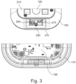
- the controller is located on a printing board of the apparatus, which printing board is illustrated in Fig. 2 , 3 , partly in Fig. 5 and 6 , in Fig. 7 and 8 .
- the controller (125) is configured to qualify at least a part of the data received from the audio sensor (115) as qualified audio data by means of an algorithm based on a reference audio standard. Further, the controller (125) is configured to qualify at least a part of the data received from the audio sensor (115) as qualified audio data by means of an algorithm based on a reference audio standard.
- the apparatus (100) illustrated comprises a transmitting member (130) configured to transmit motion data and audio data at a given point of time if the motion data and the audio data are qualified by the controller (125).
- the apparatus (100) illustrated is also configured to transmit humidity data at a given point of time if the humidity data is qualified by the controller (125).
- the identification means (140) is configured to include output data if motion data and audio data at a given point of time are qualified by the controller (125), and humidity data is qualified by the controller (125) or the external unit (135) to encompass a predetermined change in humidity as the third indication of activity in the bathroom.
- Fig. 1 , 5 , 6 , 7 and 8 illustrates the motion sensor (110) as a passive infrared sensor (PIR sensor) located below the level of the surface of the housing.
- the motion sensor is a PIR as here illustrated but may also be another type of motion sensor according to the invention.
- the apparatus (100) illustrated may further comprise (not illustrated here), a commands receiving member (145) configured to receive commands based on the qualified data at a given point of time from the external unit (135) by means of low power signals, and the controller (125) is configured to integrate the commands.
- a commands receiving member (145) configured to receive commands based on the qualified data at a given point of time from the external unit (135) by means of low power signals
- the controller (125) is configured to integrate the commands.
- FIG. 1 , 2 , 3 , 5 , 6 , 7 and 8 of the drawings there is provided illustrations of the housing of the apparatus, comprising a front cover (170) including a transparent centrally arranged portion (175) facing the front of said cover (170) that allows visibility to a display (180) positioned below the transparent centrally arranged portion (175), and a portion with a substantially thinner wall thickness (185) that allows functioning of the motion sensor (110) located below the level of the surface of the housing;
- the audio sensor (115) is protected from water droplets in the apparatus (100) by means of a trap (270) that serves to avoid water interference without substantially reducing audio signals, the trap (270) comprising a U-shaped air channel (275) starting from the face of a bottom portion (276) of the apparatus (100) and extending towards the audio sensor (115).
- the humidity sensor (120) is protected from water droplets in the apparatus (100) by means of a trap (270) that serves to avoid water interference without substantially reducing audio signals, the trap (270) comprising a U-shaped air channel (285) starting from the face of a bottom portion (276) of the apparatus (100) and extending towards the humidity sensor (120).
- a bracket (150) of the apparatus (100) fixed to the housing (105) by means of a connecting member (290), such as a screw, adjusted to secure that the audio sensor (115) in the housing (105) is tuned for optimized sound picture.
- Fig. 9 this is illustrated in Fig. 9 .
- the system is illustrated with one or more external sensors (235) communicably coupled to the apparatus (100), optionally by Bluetooth, and further including a sensor receiving member (245) in the apparatus (100) configured to receive data from the one or more external sensors (235), and the controller (125) being configured to integrate the data.
- one or more external sensors (235) communicably coupled to the apparatus (100), optionally by Bluetooth, and further including a sensor receiving member (245) in the apparatus (100) configured to receive data from the one or more external sensors (235), and the controller (125) being configured to integrate the data.
- the system may include one or more external sensors (235) include one or more external temperature sensors mounted to a water inlet (240) of a local installation (250) in the bathroom, including one or more inlets of a toilet (255), a water tap (257) or a shower (260), and the one or more external temperature sensors being configured to detect a temperature difference of the water in the inlet (240) compared to ambient temperature over time, whereby running water may be detected.
- one or more external sensors include one or more external temperature sensors mounted to a water inlet (240) of a local installation (250) in the bathroom, including one or more inlets of a toilet (255), a water tap (257) or a shower (260), and the one or more external temperature sensors being configured to detect a temperature difference of the water in the inlet (240) compared to ambient temperature over time, whereby running water may be detected.
- the system may include one or more external sensors (235) include an external temperature sensor mounted to a water inlet of a first local installation in the bathroom, such as a toilet (255), in combination with an external audio sensor in proximity to a water inlet of a second local installation in the bathroom and/or an external temperature sensor mounted to the water inlet of a second local installation in the bathroom, such as a water tap (257), whereby coordinated usage of both installations may be detected.
- an external temperature sensor mounted to a water inlet of a first local installation in the bathroom, such as a toilet (255)
- an external audio sensor in proximity to a water inlet of a second local installation in the bathroom
- an external temperature sensor mounted to the water inlet of a second local installation in the bathroom such as a water tap (257)
- system may include an alert for running water to the mobile device (230) and/or to the external unit (135), such as one or more alerts (not illustrated).
- the apparatus of the system may especially be adapted to be included in a plurality of bathrooms (not illustrated), and the external unit (135) is configured to process metadata based on qualified data from a plurality of bathrooms, optionally including said metadata in the unique identification means (140) and/or a central dashboard (142).
- the system according to the invention is illustrated and also provides an overview of the method according to the invention.
- the large, squared box illustrates the apparatus and the elements described in detail in the previous sections.
- the sensors in the apparatus include an audio sensor and a motion sensor, and optionally a humidity sensor and/or a temperature sensor.
- Data from the sensors in the apparatus are delivered to the controller where qualification of the data is performed.
- Data may further be stored in storing means in the apparatus until they are transmitted from the apparatus to an external unit, optionally via a mobile device by low power means, such as Bluetooth.
- qualified data from the controller optionally via other elements in the apparatus, is transmitted to an external unit by use of narrow band low power signals.
- Humidity data may also be transmitted to the external unit and be transmitted independently from motion and audio data.
- the qualified data is received by the external unit, further qualification may be performed by the external unit in order to achieve output data with high quality.
- data from a number of bathrooms may be transmitted to the external unit and further conveyed to a dashboard where full control of various bathrooms may be performed.
- the high-quality output is then optionally further categorised or optimized.
- commands may be transmitted back to a commands receiving member in the apparatus in order to optimize the system or pre-set requirements in the controller. For instance, more intelligent algorithms may be provided based on complete data from various bathrooms. Metadata may then be used for optimization of the systems. It may also be small adjustments or reference data that may be transmitted to the controller and incorporated in the apparatus.
- output data may be directly scanned by a mobile device on the apparatus and may provide output data includes one or more of water-saving tips, shower statistics, water tap statistics, toilet usage statistics, running water statistics and running water alerts.
- external sensors allocated to specific water installations in the bathrooms. These external sensors may be directly mounted to water pipes in close proximity to the water installations and may provide valuable data to the apparatus. Preferably, these sensors use Bluetooth but other low power means may also be used. Specifically, one option is to apply these external sensors to a toilet in order to detect if the toilet is running with water. Also, an external sensor may be provided to or close to a water tap, such as a audio sensor, that may detect running water from the water tap. In combination, if both external sensors are provided, it may detect valuable information, such as identifying derived symptoms among user of the bathroom, including diseases such as incontinence and cystitis.
Landscapes
- Physics & Mathematics (AREA)
- General Physics & Mathematics (AREA)
- Engineering & Computer Science (AREA)
- Business, Economics & Management (AREA)
- Chemical & Material Sciences (AREA)
- Health & Medical Sciences (AREA)
- Automation & Control Theory (AREA)
- Life Sciences & Earth Sciences (AREA)
- General Health & Medical Sciences (AREA)
- Tourism & Hospitality (AREA)
- Combustion & Propulsion (AREA)
- Biochemistry (AREA)
- Pathology (AREA)
- Immunology (AREA)
- Analytical Chemistry (AREA)
- Medicinal Chemistry (AREA)
- Food Science & Technology (AREA)
- Human Computer Interaction (AREA)
- Manufacturing & Machinery (AREA)
- Signal Processing (AREA)
- Economics (AREA)
- Computer Networks & Wireless Communication (AREA)
- Emergency Management (AREA)
- Theoretical Computer Science (AREA)
- General Business, Economics & Management (AREA)
- Strategic Management (AREA)
- Human Resources & Organizations (AREA)
- Primary Health Care (AREA)
- Marketing (AREA)
- Selective Calling Equipment (AREA)
- Bathtubs, Showers, And Their Attachments (AREA)
Claims (15)
- Einrichtung (100) zum Reduzieren oder Steuern des Wasserverbrauchs in Badezimmern, wobei die Einrichtung (100) ein Gehäuse (105) umfasst und konfiguriert ist, um Daten von einem oder mehreren Wasserverbrauchsstellen in einem Badezimmer zu empfangen, wobei das Gehäuse (105) umfasst:einen oder mehrere Sensoren (107), der/die einen Bewegungssensor (110), der konfiguriert ist, um eine Bewegung in einer bestimmten Entfernung von der Einrichtung in einem Badezimmer als ersten Hinweis auf Aktivität im Badezimmer zu erkennen, einen Audiosensor (115), der konfiguriert ist, um ein Geräusch von fließendem Wasser von einem oder mehreren Wasserverbrauchsstandstellen in einem Badezimmer als zweiten Hinweis auf Aktivität im Badezimmer zu überwachen, optional einen Feuchtigkeitssensor (120), der konfiguriert ist, um die Umgebungsfeuchtigkeit in einem Badezimmer als dritten Hinweis auf Aktivität im Badezimmer zu überwachen, und optional einen Umgebungstemperatursensor (200) beinhaltet/beinhalten;eine Steuereinheit (125), die konfiguriert ist, um zumindest einen Teil der von dem einen oder mehreren Sensoren (107) empfangenen Daten anhand eines Algorithmus zu qualifizieren, um qualifizierte Daten zu erhalten, wobei die Steuereinheit (125) konfiguriert ist, um zumindest einen Teil der von dem Audiosensor (115) empfangenen Daten anhand eines auf einem Referenz-Audiostandard basierenden Algorithmus als qualifizierte Audiodaten zu qualifizieren;ein Sendeelement (130), das konfiguriert ist, um die qualifizierten Daten zu einem gegebenen Zeitpunkt anhand von Signalen mit geringer Leistung, optional über eine mobile Vorrichtung (230), an eine externe Einheit (135) zu senden; undein eindeutiges Identifikationsmittel (140), das durch eine mobile Vorrichtung lesbar oder scanbar ist und konfiguriert ist, um Ausgabedaten basierend auf den qualifizierten Daten zum Reduzieren oder Steuern des Wasserverbrauchs im Badezimmer zu beinhalten.
- Einrichtung nach Anspruch 1, wobei die Steuereinheit (125) konfiguriert ist, um zumindest einen Teil der vom Bewegungssensor (110) empfangenen Daten anhand eines auf einem Referenzbewegungsstandard basierenden Algorithmus als qualifizierte Bewegungsdaten zu qualifizieren.
- Einrichtung nach Anspruch 1 oder 2, wobei der eine oder mehrere Sensoren (107) einen Feuchtigkeitssensor (120) beinhaltet/beinhalten, der/die konfiguriert ist/sind, um die Umgebungsfeuchtigkeit in einem Badezimmer als dritten Hinweis auf Aktivität im Badezimmer zu überwachen.
- Einrichtung nach Anspruch 3, wobei das Identifikationsmittel (140) konfiguriert ist, um Ausgabedaten zu beinhalten, wenn Bewegungsdaten und Audiodaten zu einem gegebenen Zeitpunkt durch die Steuereinheit (125) qualifiziert werden, und Feuchtigkeitsdaten durch die Steuereinheit (125) oder die externe Einheit (135) qualifiziert werden, eine vorbestimmte Änderung der Feuchtigkeit als dritten Hinweis auf Aktivität im Badezimmer einzuschließen.
- Einrichtung einem der vorstehenden Ansprüche, wobei der eine oder mehrere Sensoren (107) einen Umgebungstemperatursensor (200) beinhaltet/beinhalten.
- Einrichtung nach einem der vorstehenden Ansprüche, wobei der eine oder mehrere Sensoren (107) einen Kohlendioxidsensor beinhaltet/beinhalten und das Identifikationsmittel (140) konfiguriert ist, um Ausgabedaten zu beinhalten, wenn Kohlendioxiddaten zu einem gegebenen Zeitpunkt durch die Steuereinheit (125) oder die externe Einheit (135) qualifiziert werden.
- Einrichtung nach einem der vorstehenden Ansprüche, wobei das Gehäuse (105) weiter ein Befehlsempfangselement (145) umfasst, das konfiguriert ist, um zu einem gegebenen Zeitpunkt auf den qualifizierten Daten basierende Befehle von der externen Einheit (135) anhand von Signalen mit geringer Leistung zu empfangen, und wobei die Steuereinheit (125) konfiguriert ist, um die Befehle zu integrieren.
- Einrichtung (100) nach einem der vorstehenden Ansprüche, wobei das Gehäuse (105) umfasst:eine vordere Abdeckung (170), die einen transparenten, mittig angeordneten Abschnitt (175) beinhaltet, der zur Vorderseite der Abdeckung (170) weist und die Sicht auf eine Anzeige (180) erlaubt, die unterhalb des transparenten, mittig angeordneten Abschnitts (175) positioniert ist, und einen Abschnitt mit einer wesentlich dünneren Wandstärke (185), der die Funktion des Bewegungssensors (110) erlaubt, der sich unterhalb der Ebene der Oberfläche des Gehäuses befindet;eine hintere Abdeckung (190), die mit der vorderen Abdeckung (170) verbindbar und versiegelbar ist, wobei die hintere Abdeckung (190) eine Druckplatte (195) umschließt und die Druckplatte (195) die Anzeige (180) beinhaltet, die betreibbar ist, um den eindeutigen Matrix-Barcode (140), den einen und mehrere Sensoren, die Steuereinheit (125) und das Sendeelement (130) zu visualisieren;eine hintere Platte (210), die mit der hinteren Abdeckung (190) verbindbar und versiegelbar ist, wobei die hintere Platte und die hintere Abdeckung ein Stromversorgungselement (220) zum Betreiben der Einrichtung umschließen.
- Einrichtung nach einem der vorstehenden Ansprüche, wobei die Ausgabedaten eines oder mehr von Tipps zum Wassersparen, Duschstatistiken, Wasserhahnstatistiken, Toilettenbenutzungsstatistiken, Statistiken zu fließendem Wasser und Warnungen zu fließendem Wasser beinhalten.
- System (201) zum Reduzieren oder Steuern des Wasserverbrauchs in Badezimmern, wobei das System umfasst:eine Einrichtung (100) nach einem der vorstehenden Ansprüche;eine externe Einheit (135), die konfiguriert ist, um zu einem gegebenen Zeitpunkt qualifizierte Daten von der Einrichtung (100) anhand von Signalen mit geringer Leistung, optional über eine mobile Vorrichtung (230) zu empfangen, und die konfiguriert ist, um Daten basierend auf den qualifizierten Daten und/oder basierend auf einer weiteren Qualifizierung von Daten, wie etwa Feuchtigkeitsdaten zu verarbeiten, und konfiguriert, um Ausgabedaten in ein eindeutiges Identifikationsmittel (140) zu integrieren, das von einer mobilen Vorrichtung (230) in der Einrichtung (100) zum Reduzieren oder Steuern des Wasserverbrauchs in einem Badezimmer lesbar ist;optional ein Befehlsempfangselement (240) in der Einrichtung (100), das konfiguriert ist, um zu einem gegebenen Zeitpunkt auf den qualifizierten Daten basierende Befehle von der externen Einheit (135) anhand von Signalen mit geringer Leistung zu empfangen, und die Steuereinheit (125) konfiguriert ist, um die Befehle zu integrieren; undeine mobile Vorrichtung (230), die betreibbar ist, um das eindeutige Identifikationsmittel (140) zu lesen.
- System nach Anspruch 10, wobei der eine oder mehrere externe Sensoren (235) einen oder mehrere externe Temperatursensoren beinhaltet/beinhalten, die an einem Wassereinlass (240) einer lokalen Installation (250) im Badezimmer montiert sind, die einen oder mehrere Einlässen einer Toilette (255), eines Wasserhahns (257) oder einer Dusche (260) beinhalten, und wobei der eine oder mehrere externe Temperatursensoren konfiguriert ist/sind, um einen Temperaturunterschied des Wassers im Einlass (240) im Vergleich zur Umgebungstemperatur im Laufe der Zeit zu erkennen, wodurch fließendes Wasser erkannt werden kann.
- System nach einem der Ansprüche 10-11, wobei der eine oder mehrere externe Sensoren (235) einen externen Temperatursensor beinhaltet/beinhalten, der an einem Wassereinlass einer ersten lokalen Installation im Badezimmer, wie beispielsweise einer Toilette (255), montiert ist, in Kombination mit einem externen Audiosensor in der Nähe eines Wassereinlasses einer zweiten lokalen Installation im Badezimmer und/oder ein externer Temperatursensor, der am Wassereinlass einer zweiten lokalen Installation im Badezimmer, beispielsweise einem Wasserhahn (257), montiert ist, wodurch eine koordinierte Nutzung beider Installationen erkannt werden kann.
- System nach einem der Ansprüche 10-12, das weiter eine Warnung für fließendes Wasser an die mobile Vorrichtung (230) und/oder an die Außeneinheit (135) beinhaltet.
- Verfahren zum Reduzieren oder Steuern des Wasserverbrauchs in Badezimmern, wobei das Verfahren die Schritte umfasst zum:Bereitstellen einer Einrichtung (100), die konfiguriert ist, um Daten von einem oder mehreren Wasserverbrauchsstellen in einem Badezimmer zu empfangen, wobei die Einrichtung ein Gehäuse (105) umfasst, das eine oder mehrere Sensoren (107), eine Steuereinheit (125), ein Sendeelement (130) und ein eindeutiges Identifikationsmittel (140) beinhaltet;Erkennen einer Bewegung in einer bestimmten Entfernung von der Einrichtung (100) in einem Badezimmer als ersten Hinweis auf Aktivität im Badezimmer anhand eines Bewegungssensors (110), Erkennen eines Geräusches von fließendem Wasser von einem oder mehreren Wasserverbrauchsstellen in einem Badezimmer als zweiten Hinweis auf Aktivität im Badezimmer anhand eines Audiosensors (115), optional Erkennen der Umgebungsfeuchtigkeit in einem Badezimmer als dritten Hinweis auf Aktivität im Badezimmer anhand eines Feuchtigkeitssensors (120), und optional Erkennen der Umgebungstemperatur anhand eines Umgebungstemperatursensors (200);Qualifizieren von zumindest einem Teil der von einem oder mehreren Sensoren (107) empfangenen Daten anhand eines Algorithmus, um qualifizierte Daten zu erhalten, wobei die Daten Daten beinhalten, die von dem Audiosensor (115) als qualifizierte Audiodaten basierend auf einem Referenz-Audiostandard empfangen wurden;Senden der qualifizierten Daten zu einem gegebenen Zeitpunkt, optional über eine mobile Vorrichtung (230), an eine externe Einheit (135) anhand von Signalen mit geringer Leistung; undUnterwerfen von auf den qualifizierten Daten basierenden Ausgabedaten zum Reduzieren oder Steuern des Wasserverbrauchs im Badezimmer einem eindeutigen Identifikationsmittel (140), das durch eine mobile Vorrichtung (230) lesbar oder scanbar ist.
- Verfahren nach Anspruch 14, wobei das Verfahren in einer Einrichtung (100) und/oder einem System (201) nach den Ansprüchen 1-13 angewendet wird.
Applications Claiming Priority (2)
| Application Number | Priority Date | Filing Date | Title |
|---|---|---|---|
| DKPA202070854 | 2020-12-18 | ||
| PCT/DK2021/050370 WO2022128036A1 (en) | 2020-12-18 | 2021-12-16 | An apparatus for controlling water consumption in bathrooms |
Publications (3)
| Publication Number | Publication Date |
|---|---|
| EP4264191A1 EP4264191A1 (de) | 2023-10-25 |
| EP4264191C0 EP4264191C0 (de) | 2024-11-06 |
| EP4264191B1 true EP4264191B1 (de) | 2024-11-06 |
Family
ID=80050955
Family Applications (1)
| Application Number | Title | Priority Date | Filing Date |
|---|---|---|---|
| EP21848251.1A Active EP4264191B1 (de) | 2020-12-18 | 2021-12-16 | Vorrichtung zur steuerung des wasserverbrauchs in badezimmern |
Country Status (4)
| Country | Link |
|---|---|
| US (1) | US20240060945A1 (de) |
| EP (1) | EP4264191B1 (de) |
| ES (1) | ES3011726T3 (de) |
| WO (1) | WO2022128036A1 (de) |
Families Citing this family (1)
| Publication number | Priority date | Publication date | Assignee | Title |
|---|---|---|---|---|
| MA63866A1 (fr) * | 2024-01-15 | 2025-07-31 | KHARKI Abdellah EL | Mesure Innovante pour la Conservation de l'Eau dans les Hammams publics : Vers une gestion écologique de l’eau |
Family Cites Families (3)
| Publication number | Priority date | Publication date | Assignee | Title |
|---|---|---|---|---|
| US9749792B2 (en) * | 2009-08-11 | 2017-08-29 | Michael Edward Klicpera | Water use monitoring apparatus |
| US10887125B2 (en) * | 2017-09-15 | 2021-01-05 | Kohler Co. | Bathroom speaker |
| CN111926697A (zh) * | 2020-08-31 | 2020-11-13 | 中联西北工程设计研究院有限公司 | 一种桥面积水分流排水防污染系统及方法 |
-
2021
- 2021-12-16 EP EP21848251.1A patent/EP4264191B1/de active Active
- 2021-12-16 ES ES21848251T patent/ES3011726T3/es active Active
- 2021-12-16 WO PCT/DK2021/050370 patent/WO2022128036A1/en not_active Ceased
- 2021-12-16 US US18/267,008 patent/US20240060945A1/en active Pending
Also Published As
| Publication number | Publication date |
|---|---|
| ES3011726T3 (en) | 2025-04-08 |
| EP4264191C0 (de) | 2024-11-06 |
| WO2022128036A1 (en) | 2022-06-23 |
| EP4264191A1 (de) | 2023-10-25 |
| US20240060945A1 (en) | 2024-02-22 |
Similar Documents
| Publication | Publication Date | Title |
|---|---|---|
| US11676471B2 (en) | Swimming pool monitoring | |
| US11594111B2 (en) | Intelligent wake-up system | |
| CA3141725A1 (en) | Smart water valve | |
| US10732069B2 (en) | Fluid flow detection and analysis device and system | |
| US11583883B2 (en) | System and method for controlling and monitoring bathroom water flow | |
| US12207171B2 (en) | Smart speakerphone emergency monitoring | |
| NL2017519B1 (en) | Device for and method of fluid flow monitoring. | |
| KR20090012032A (ko) | 공조 설비 통제 제어 시스템 | |
| US11255076B2 (en) | System and method for controlling and monitoring bathroom water flow | |
| US20100141397A1 (en) | System for activity recognition | |
| CN103954017A (zh) | 一种智能遥控器及其控制方法 | |
| EP4264191B1 (de) | Vorrichtung zur steuerung des wasserverbrauchs in badezimmern | |
| US20240027297A1 (en) | Humidity monitoring | |
| JP7403761B2 (ja) | 要介護者見守り支援システム | |
| WO2006013512A1 (en) | Low cost acoustic responder location system | |
| CN207849678U (zh) | 一种分体空调集中控制系统 | |
| CN105357571A (zh) | 一种基于智能电视屏幕的智能家居系统及实现方法 | |
| US11466869B1 (en) | Integrated hot water recirculation system | |
| TW202330107A (zh) | 用於節約水及能量消耗之系統及方法 | |
| CN104864554A (zh) | 空调器及其控制方法、可穿戴设备、智能控制设备 | |
| JP6415919B2 (ja) | 情報報知システム及び情報報知方法 | |
| CN110426963A (zh) | 一种兼容wifi和蓝牙技术的智能家居管理装置 | |
| KR20240153073A (ko) | 통신 기반의 공기질 통합제어 시스템 | |
| IT201800002863A1 (it) | Sistema di monitoraggio e controllo con sensore acustico | |
| IT201800002865A1 (it) | Sistema di monitoraggio e controllo con sensore per la misurazione indiretta della concentrazione di co2 |
Legal Events
| Date | Code | Title | Description |
|---|---|---|---|
| STAA | Information on the status of an ep patent application or granted ep patent |
Free format text: STATUS: UNKNOWN |
|
| STAA | Information on the status of an ep patent application or granted ep patent |
Free format text: STATUS: THE INTERNATIONAL PUBLICATION HAS BEEN MADE |
|
| PUAI | Public reference made under article 153(3) epc to a published international application that has entered the european phase |
Free format text: ORIGINAL CODE: 0009012 |
|
| STAA | Information on the status of an ep patent application or granted ep patent |
Free format text: STATUS: REQUEST FOR EXAMINATION WAS MADE |
|
| 17P | Request for examination filed |
Effective date: 20230615 |
|
| AK | Designated contracting states |
Kind code of ref document: A1 Designated state(s): AL AT BE BG CH CY CZ DE DK EE ES FI FR GB GR HR HU IE IS IT LI LT LU LV MC MK MT NL NO PL PT RO RS SE SI SK SM TR |
|
| DAV | Request for validation of the european patent (deleted) | ||
| DAX | Request for extension of the european patent (deleted) | ||
| GRAP | Despatch of communication of intention to grant a patent |
Free format text: ORIGINAL CODE: EPIDOSNIGR1 |
|
| STAA | Information on the status of an ep patent application or granted ep patent |
Free format text: STATUS: GRANT OF PATENT IS INTENDED |
|
| RIC1 | Information provided on ipc code assigned before grant |
Ipc: H04L 12/28 20060101ALI20240701BHEP Ipc: G08B 21/20 20060101ALI20240701BHEP Ipc: G06Q 50/163 20240101ALI20240701BHEP Ipc: G01F 9/00 20060101ALI20240701BHEP Ipc: G06Q 50/06 20120101ALI20240701BHEP Ipc: G08B 21/00 20060101ALI20240701BHEP Ipc: G01D 21/02 20060101ALI20240701BHEP Ipc: G01D 21/00 20060101ALI20240701BHEP Ipc: G01D 4/00 20060101ALI20240701BHEP Ipc: G01D 11/24 20060101AFI20240701BHEP |
|
| INTG | Intention to grant announced |
Effective date: 20240712 |
|
| GRAS | Grant fee paid |
Free format text: ORIGINAL CODE: EPIDOSNIGR3 |
|
| GRAA | (expected) grant |
Free format text: ORIGINAL CODE: 0009210 |
|
| STAA | Information on the status of an ep patent application or granted ep patent |
Free format text: STATUS: THE PATENT HAS BEEN GRANTED |
|
| AK | Designated contracting states |
Kind code of ref document: B1 Designated state(s): AL AT BE BG CH CY CZ DE DK EE ES FI FR GB GR HR HU IE IS IT LI LT LU LV MC MK MT NL NO PL PT RO RS SE SI SK SM TR |
|
| RAP3 | Party data changed (applicant data changed or rights of an application transferred) |
Owner name: AGUARDIO APS |
|
| REG | Reference to a national code |
Ref country code: GB Ref legal event code: FG4D |
|
| RIN1 | Information on inventor provided before grant (corrected) |
Inventor name: SKOUBOE, KRISTIAN REESEN Inventor name: MUNCH-LAURSEN, THOMAS |
|
| REG | Reference to a national code |
Ref country code: CH Ref legal event code: EP |
|
| REG | Reference to a national code |
Ref country code: DE Ref legal event code: R096 Ref document number: 602021021610 Country of ref document: DE |
|
| REG | Reference to a national code |
Ref country code: IE Ref legal event code: FG4D |
|
| U01 | Request for unitary effect filed |
Effective date: 20241120 |
|
| RAP4 | Party data changed (patent owner data changed or rights of a patent transferred) |
Owner name: AGUARDIO APS |
|
| U07 | Unitary effect registered |
Designated state(s): AT BE BG DE DK EE FI FR IT LT LU LV MT NL PT RO SE SI Effective date: 20241128 |
|
| U20 | Renewal fee for the european patent with unitary effect paid |
Year of fee payment: 4 Effective date: 20241209 |
|
| REG | Reference to a national code |
Ref country code: ES Ref legal event code: FG2A Ref document number: 3011726 Country of ref document: ES Kind code of ref document: T3 Effective date: 20250408 |
|
| PG25 | Lapsed in a contracting state [announced via postgrant information from national office to epo] |
Ref country code: IS Free format text: LAPSE BECAUSE OF FAILURE TO SUBMIT A TRANSLATION OF THE DESCRIPTION OR TO PAY THE FEE WITHIN THE PRESCRIBED TIME-LIMIT Effective date: 20250306 Ref country code: HR Free format text: LAPSE BECAUSE OF FAILURE TO SUBMIT A TRANSLATION OF THE DESCRIPTION OR TO PAY THE FEE WITHIN THE PRESCRIBED TIME-LIMIT Effective date: 20241106 |
|
| PG25 | Lapsed in a contracting state [announced via postgrant information from national office to epo] |
Ref country code: NO Free format text: LAPSE BECAUSE OF FAILURE TO SUBMIT A TRANSLATION OF THE DESCRIPTION OR TO PAY THE FEE WITHIN THE PRESCRIBED TIME-LIMIT Effective date: 20250206 |
|
| PG25 | Lapsed in a contracting state [announced via postgrant information from national office to epo] |
Ref country code: GR Free format text: LAPSE BECAUSE OF FAILURE TO SUBMIT A TRANSLATION OF THE DESCRIPTION OR TO PAY THE FEE WITHIN THE PRESCRIBED TIME-LIMIT Effective date: 20250207 |
|
| PG25 | Lapsed in a contracting state [announced via postgrant information from national office to epo] |
Ref country code: PL Free format text: LAPSE BECAUSE OF FAILURE TO SUBMIT A TRANSLATION OF THE DESCRIPTION OR TO PAY THE FEE WITHIN THE PRESCRIBED TIME-LIMIT Effective date: 20241106 |
|
| PG25 | Lapsed in a contracting state [announced via postgrant information from national office to epo] |
Ref country code: RS Free format text: LAPSE BECAUSE OF FAILURE TO SUBMIT A TRANSLATION OF THE DESCRIPTION OR TO PAY THE FEE WITHIN THE PRESCRIBED TIME-LIMIT Effective date: 20250206 |
|
| PG25 | Lapsed in a contracting state [announced via postgrant information from national office to epo] |
Ref country code: SM Free format text: LAPSE BECAUSE OF FAILURE TO SUBMIT A TRANSLATION OF THE DESCRIPTION OR TO PAY THE FEE WITHIN THE PRESCRIBED TIME-LIMIT Effective date: 20241106 |
|
| PG25 | Lapsed in a contracting state [announced via postgrant information from national office to epo] |
Ref country code: SK Free format text: LAPSE BECAUSE OF FAILURE TO SUBMIT A TRANSLATION OF THE DESCRIPTION OR TO PAY THE FEE WITHIN THE PRESCRIBED TIME-LIMIT Effective date: 20241106 |
|
| PG25 | Lapsed in a contracting state [announced via postgrant information from national office to epo] |
Ref country code: CZ Free format text: LAPSE BECAUSE OF FAILURE TO SUBMIT A TRANSLATION OF THE DESCRIPTION OR TO PAY THE FEE WITHIN THE PRESCRIBED TIME-LIMIT Effective date: 20241106 |
|
| REG | Reference to a national code |
Ref country code: CH Ref legal event code: PL |
|
| PLBE | No opposition filed within time limit |
Free format text: ORIGINAL CODE: 0009261 |
|
| STAA | Information on the status of an ep patent application or granted ep patent |
Free format text: STATUS: NO OPPOSITION FILED WITHIN TIME LIMIT |
|
| PG25 | Lapsed in a contracting state [announced via postgrant information from national office to epo] |
Ref country code: MC Free format text: LAPSE BECAUSE OF FAILURE TO SUBMIT A TRANSLATION OF THE DESCRIPTION OR TO PAY THE FEE WITHIN THE PRESCRIBED TIME-LIMIT Effective date: 20241106 |
|
| 26N | No opposition filed |
Effective date: 20250807 |
|
| PG25 | Lapsed in a contracting state [announced via postgrant information from national office to epo] |
Ref country code: CH Free format text: LAPSE BECAUSE OF NON-PAYMENT OF DUE FEES Effective date: 20241231 |
|
| PG25 | Lapsed in a contracting state [announced via postgrant information from national office to epo] |
Ref country code: IE Free format text: LAPSE BECAUSE OF NON-PAYMENT OF DUE FEES Effective date: 20241216 |
|
| PGFP | Annual fee paid to national office [announced via postgrant information from national office to epo] |
Ref country code: GB Payment date: 20251208 Year of fee payment: 5 |
|
| U20 | Renewal fee for the european patent with unitary effect paid |
Year of fee payment: 5 Effective date: 20251208 |
|
| PGFP | Annual fee paid to national office [announced via postgrant information from national office to epo] |
Ref country code: ES Payment date: 20260108 Year of fee payment: 5 |