EP4264098B1 - Herstellung von rohr-in-rohr-anordnungen - Google Patents
Herstellung von rohr-in-rohr-anordnungen Download PDFInfo
- Publication number
- EP4264098B1 EP4264098B1 EP21854815.4A EP21854815A EP4264098B1 EP 4264098 B1 EP4264098 B1 EP 4264098B1 EP 21854815 A EP21854815 A EP 21854815A EP 4264098 B1 EP4264098 B1 EP 4264098B1
- Authority
- EP
- European Patent Office
- Prior art keywords
- elements
- assembly
- reinforcing
- insulating
- pipe
- Prior art date
- Legal status (The legal status is an assumption and is not a legal conclusion. Google has not performed a legal analysis and makes no representation as to the accuracy of the status listed.)
- Active
Links
Images


Classifications
-
- F—MECHANICAL ENGINEERING; LIGHTING; HEATING; WEAPONS; BLASTING
- F16—ENGINEERING ELEMENTS AND UNITS; GENERAL MEASURES FOR PRODUCING AND MAINTAINING EFFECTIVE FUNCTIONING OF MACHINES OR INSTALLATIONS; THERMAL INSULATION IN GENERAL
- F16L—PIPES; JOINTS OR FITTINGS FOR PIPES; SUPPORTS FOR PIPES, CABLES OR PROTECTIVE TUBING; MEANS FOR THERMAL INSULATION IN GENERAL
- F16L11/00—Hoses, i.e. flexible pipes
- F16L11/04—Hoses, i.e. flexible pipes made of rubber or flexible plastics
- F16L11/08—Hoses, i.e. flexible pipes made of rubber or flexible plastics with reinforcements embedded in the wall
-
- F—MECHANICAL ENGINEERING; LIGHTING; HEATING; WEAPONS; BLASTING
- F16—ENGINEERING ELEMENTS AND UNITS; GENERAL MEASURES FOR PRODUCING AND MAINTAINING EFFECTIVE FUNCTIONING OF MACHINES OR INSTALLATIONS; THERMAL INSULATION IN GENERAL
- F16L—PIPES; JOINTS OR FITTINGS FOR PIPES; SUPPORTS FOR PIPES, CABLES OR PROTECTIVE TUBING; MEANS FOR THERMAL INSULATION IN GENERAL
- F16L53/00—Heating of pipes or pipe systems; Cooling of pipes or pipe systems
- F16L53/30—Heating of pipes or pipe systems
- F16L53/35—Ohmic-resistance heating
- F16L53/38—Ohmic-resistance heating using elongate electric heating elements, e.g. wires or ribbons
-
- F—MECHANICAL ENGINEERING; LIGHTING; HEATING; WEAPONS; BLASTING
- F16—ENGINEERING ELEMENTS AND UNITS; GENERAL MEASURES FOR PRODUCING AND MAINTAINING EFFECTIVE FUNCTIONING OF MACHINES OR INSTALLATIONS; THERMAL INSULATION IN GENERAL
- F16L—PIPES; JOINTS OR FITTINGS FOR PIPES; SUPPORTS FOR PIPES, CABLES OR PROTECTIVE TUBING; MEANS FOR THERMAL INSULATION IN GENERAL
- F16L59/00—Thermal insulation in general
- F16L59/02—Shape or form of insulating materials, with or without coverings integral with the insulating materials
- F16L59/029—Shape or form of insulating materials, with or without coverings integral with the insulating materials layered
-
- F—MECHANICAL ENGINEERING; LIGHTING; HEATING; WEAPONS; BLASTING
- F16—ENGINEERING ELEMENTS AND UNITS; GENERAL MEASURES FOR PRODUCING AND MAINTAINING EFFECTIVE FUNCTIONING OF MACHINES OR INSTALLATIONS; THERMAL INSULATION IN GENERAL
- F16L—PIPES; JOINTS OR FITTINGS FOR PIPES; SUPPORTS FOR PIPES, CABLES OR PROTECTIVE TUBING; MEANS FOR THERMAL INSULATION IN GENERAL
- F16L59/00—Thermal insulation in general
- F16L59/06—Arrangements using an air layer or vacuum
-
- F—MECHANICAL ENGINEERING; LIGHTING; HEATING; WEAPONS; BLASTING
- F16—ENGINEERING ELEMENTS AND UNITS; GENERAL MEASURES FOR PRODUCING AND MAINTAINING EFFECTIVE FUNCTIONING OF MACHINES OR INSTALLATIONS; THERMAL INSULATION IN GENERAL
- F16L—PIPES; JOINTS OR FITTINGS FOR PIPES; SUPPORTS FOR PIPES, CABLES OR PROTECTIVE TUBING; MEANS FOR THERMAL INSULATION IN GENERAL
- F16L59/00—Thermal insulation in general
- F16L59/14—Arrangements for the insulation of pipes or pipe systems
- F16L59/143—Pre-insulated pipes
-
- F—MECHANICAL ENGINEERING; LIGHTING; HEATING; WEAPONS; BLASTING
- F16—ENGINEERING ELEMENTS AND UNITS; GENERAL MEASURES FOR PRODUCING AND MAINTAINING EFFECTIVE FUNCTIONING OF MACHINES OR INSTALLATIONS; THERMAL INSULATION IN GENERAL
- F16L—PIPES; JOINTS OR FITTINGS FOR PIPES; SUPPORTS FOR PIPES, CABLES OR PROTECTIVE TUBING; MEANS FOR THERMAL INSULATION IN GENERAL
- F16L59/00—Thermal insulation in general
- F16L59/14—Arrangements for the insulation of pipes or pipe systems
- F16L59/147—Arrangements for the insulation of pipes or pipe systems the insulation being located inwardly of the outer surface of the pipe
-
- F—MECHANICAL ENGINEERING; LIGHTING; HEATING; WEAPONS; BLASTING
- F16—ENGINEERING ELEMENTS AND UNITS; GENERAL MEASURES FOR PRODUCING AND MAINTAINING EFFECTIVE FUNCTIONING OF MACHINES OR INSTALLATIONS; THERMAL INSULATION IN GENERAL
- F16L—PIPES; JOINTS OR FITTINGS FOR PIPES; SUPPORTS FOR PIPES, CABLES OR PROTECTIVE TUBING; MEANS FOR THERMAL INSULATION IN GENERAL
- F16L9/00—Rigid pipes
- F16L9/02—Rigid pipes of metal
- F16L9/04—Reinforced pipes
- F16L9/042—Reinforced pipes the reinforcement comprising one or more layers of a helically wound cord, wire or strip
-
- F—MECHANICAL ENGINEERING; LIGHTING; HEATING; WEAPONS; BLASTING
- F16—ENGINEERING ELEMENTS AND UNITS; GENERAL MEASURES FOR PRODUCING AND MAINTAINING EFFECTIVE FUNCTIONING OF MACHINES OR INSTALLATIONS; THERMAL INSULATION IN GENERAL
- F16L—PIPES; JOINTS OR FITTINGS FOR PIPES; SUPPORTS FOR PIPES, CABLES OR PROTECTIVE TUBING; MEANS FOR THERMAL INSULATION IN GENERAL
- F16L9/00—Rigid pipes
- F16L9/14—Compound tubes, i.e. made of materials not wholly covered by any one of the preceding groups
- F16L9/147—Compound tubes, i.e. made of materials not wholly covered by any one of the preceding groups comprising only layers of metal and plastics with or without reinforcement
-
- F—MECHANICAL ENGINEERING; LIGHTING; HEATING; WEAPONS; BLASTING
- F16—ENGINEERING ELEMENTS AND UNITS; GENERAL MEASURES FOR PRODUCING AND MAINTAINING EFFECTIVE FUNCTIONING OF MACHINES OR INSTALLATIONS; THERMAL INSULATION IN GENERAL
- F16L—PIPES; JOINTS OR FITTINGS FOR PIPES; SUPPORTS FOR PIPES, CABLES OR PROTECTIVE TUBING; MEANS FOR THERMAL INSULATION IN GENERAL
- F16L9/00—Rigid pipes
- F16L9/18—Double-walled pipes; Multi-channel pipes or pipe assemblies
-
- F—MECHANICAL ENGINEERING; LIGHTING; HEATING; WEAPONS; BLASTING
- F16—ENGINEERING ELEMENTS AND UNITS; GENERAL MEASURES FOR PRODUCING AND MAINTAINING EFFECTIVE FUNCTIONING OF MACHINES OR INSTALLATIONS; THERMAL INSULATION IN GENERAL
- F16L—PIPES; JOINTS OR FITTINGS FOR PIPES; SUPPORTS FOR PIPES, CABLES OR PROTECTIVE TUBING; MEANS FOR THERMAL INSULATION IN GENERAL
- F16L59/00—Thermal insulation in general
- F16L59/02—Shape or form of insulating materials, with or without coverings integral with the insulating materials
- F16L59/028—Compositions for or methods of fixing a thermally insulating material
Definitions
- This invention relates to the manufacture of pipe-in-pipe (PiP) assemblies, for example as used for pipelines in the subsea oil and gas industry.
- the invention relates particularly to the challenges of simplifying and accelerating the manufacture of PiP assemblies.
- references to pipelines include multiple pipe joints and pipe stalks that are fabricated from a succession of pipe joints and that are then welded together, in turn, to form longer pipelines.
- pipe stalks of up to a few kilometres in length may be manufactured at a coastal spoolbase in support of offshore reel-lay operations.
- Pipelines may, for example, be used underwater as 'tie-backs' to transport crude oil and/or natural gas from a subsea wellhead across the seabed on the way to the surface, typically via a riser.
- the produced fluid emerges from the wellhead at high temperature and pressure and then enters a subsea pipeline.
- the temperature and pressure of the produced fluid have to be kept high enough to ensure a sufficient flow rate across the seabed and up the riser.
- various measures are taken to ensure that the internal temperature of the pipeline remains high despite thermal exchange with the much colder surrounding seawater.
- a conventional PiP assembly is an example of passive thermal management, comprising a fluid-carrying inner pipe or flowline positioned concentrically within an outer pipe.
- the inner and outer pipes are spaced from each other, for example by longitudinally-distributed, radially-extending centralisers or spacers, to define a thermally-insulating annulus between them.
- layers or blankets of thermal insulation material are also disposed in the annulus, usually placed in the longitudinal gaps between spacers. It is also possible to draw down a partial vacuum in the annulus or to inject an insulating gas to reduce transmission of heat through the annulus.
- a trace heating system typically employs resistive electrical cables running along, and in thermal contact with, the outer surface of a steel pipeline.
- the cables may extend in straight lines parallel to the central longitudinal axis of the pipeline, in a helix spiralling around the longitudinal axis, or in wavy pattern such as an 'S-Z' pattern that extends both circumferentially and longitudinally. Heat produced by passing an electric current along the cables is conducted through the pipe wall to the production fluid flowing within.
- Electrically trace-heated PiP employs a combination of passive and active thermal management to manage the temperature of production fluids optimally.
- resistive electrical cables are disposed within the annulus between the inner and outer pipes, in thermal contact with the inner pipe.
- the cables are buried beneath, or radially within, thermal insulation material also disposed in the annulus.
- the cables may also pass through or beneath spacers, or other structures such as bulkheads or anodes, that extend radially across the annulus.
- Auxiliary cables may also be installed along a pipeline, such as fibre-optic cables to carry data for communication, control or monitoring purposes, or conductive cables to convey electrical power along the pipeline.
- auxiliary cables may conveniently be accommodated within the annulus.
- an insulated pipeline comprises an inner pipe and an outer polymer sleeve that is co-axial with the inner pipe.
- the inner pipe and the outer sleeve are spaced apart to define an annulus between them.
- a thermally-insulating core within the annulus comprises pre-cured, extruded, cylindrical syntactic elements and a binder that fills the interstices between those elements.
- this is not a PiP structure, as evidenced by the requirement for syntactic elements to resist hydrostatic pressure.
- Syntactic elements an example of 'wet' insulation, are mechanically strong but are much less efficient as thermal insulators than more fragile 'dry' insulation materials, such as aerogels, which can be used in a PiP assembly whose outer pipe resists hydrostatic pressure.
- US 9863571 teaches filling the annulus of a PiP assembly with a plurality of hollow tubes or compartments whose primary purpose is thermal insulation.
- An outer encasement pipe made of composite material provides mechanical protection.
- US 2014/230946 describes a flexible pipe that includes armour layers and insulation layers.
- the function of the insulation layers is to ensure a sufficient thermal insulation between the fluid transported inside the pipe and the surrounding armour layer.
- the insulation element may also be placed on, around or onto the outside of the inner liner, between the pressure armouring layers and the tensile armouring layers. A further insulation element position is on the outside of the tensile armouring layers.
- US 9863571 describes a subsea pipeline that includes an insulating layer formed by a plurality of elongate elements each containing an insulation material.
- CN 108758110 recognises this need by placing a layer of tubes of oval cross-section within the annulus of a PiP assembly.
- the long axis of the oval cross-section of each tube extends radially to improve mechanical resistance to radial compression.
- the tubes are neither ideally strong nor ideally thermally insulating.
- the invention contemplates a pipe-in-pipe assembly comprising a bundled infill structure occupying an annulus between inner and outer pipes of the assembly, the infill structure being formed of a plurality of elongate elements laid along the inner pipe.
- the elongate elements of the infill structure comprise a mixture of reinforcing elements and insulating elements, the reinforcing elements having greater mechanical resistance than the insulating elements to radial compression whereas the insulating elements provide greater thermal insulation than the reinforcing elements.
- Pluralities of the reinforcing elements are positioned together within the infill structure to form reinforcing formations that are embedded between insulating regions of the infill structure defined by pluralities of the insulating elements.
- the infill structure preferably comprises layers of the elongate elements laid on the inner pipe in radially-outward succession.
- the elongate elements of each layer may be angularly staggered relative to the elongate elements of each neighbouring layer.
- the reinforcing formations may incorporate fewer reinforcing elements in successive layers to taper in a radially outward direction.
- the reinforcing formations preferably extend through a full radial thickness of the infill structure. Nevertheless, there may be a radial gap between the infill structure and the outer pipe, which gap is preferably continuous circumferentially around the infill structure and within the outer pipe.
- the reinforcing formations are spacer formations that are angularly spaced around the inner pipe and that extend radially from the inner pipe toward the outer pipe.
- the spacer formations may each comprise only reinforcing elements or a combination of the reinforcing elements and the insulating elements.
- the elongate elements of the infill structure may further comprise one or more auxiliary elements whose primary purpose is to heat the inner pipe or to convey electrical current or data along the assembly.
- one or more of the auxiliary elements may be a heating element that is in thermal contact with the inner pipe and that is surrounded by insulating elements of the infill structure.
- one or more of the auxiliary elements may be a data cable that is separated from the inner pipe and from any heating element by at least one insulating element or reinforcing element of the infill structure.
- the elongate elements may lie on mutually parallel paths, for example on helical paths, and may comprise groups of elements braided, knitted, wrapped, twisted, bonded or fused together.
- the reinforcing elements may comprise tubes or rods whereas the insulating elements may comprise: hollow tubes; tubes filled with thermally insulating material; solid rods of thermally insulating material; or elements of a fibrous thermally insulating material. Where the reinforcing elements and the insulating elements are both tubular, the tubes of the insulating elements suitably have thinner walls than the tubes of the reinforcing elements.
- the elongate elements of the infill structure could all be of substantially the same diameter or could increase in diameter in a radially-outward direction.
- the inventive concept embraces a corresponding method of manufacturing a pipe-in-pipe assembly.
- the method comprises: forming a bundled infill structure around an inner pipe of the assembly by laying a plurality of elongate elements along the inner pipe; and inserting the inner pipe and the infill structure into an outer pipe of the assembly, the infill structure then occupying an annulus defined between the inner and outer pipes.
- the elongate elements of the infill structure comprise a mixture of reinforcing elements and insulating elements.
- the reinforcing elements are placed together within the infill structure to form reinforcing formations, each of those formations comprising a plurality of the reinforcing elements and being embedded between insulating regions of the infill structure defined by pluralities of the insulating elements.
- the reinforcing formations may be tapered in a radially outward direction by incorporating fewer reinforcing elements in successive layers.
- the method may comprise laying at least one heating element in thermal contact with the inner pipe and laying insulating elements over and surrounding the at least one heating element.
- the method may also, or alternatively, comprise laying at least one data cable on at least one inner layer of elongate elements, such as insulating elements, disposed between the data cable and the inner pipe.
- the elongate elements laid on the inner pipe may be dispensed or unspooled from at least one reel of a winding machine.
- the elongate elements may be laid successively on the inner pipe at positions spaced longitudinally along the inner pipe.
- a plurality of the elongate elements may be grouped together at a common longitudinal and/or circumferential position on the inner pipe.
- the elongate elements may be grouped by convergence from respective reels to the common position on the inner pipe, or may be grouped, for example by braiding, before being conveyed together to the inner pipe as a group.
- the infill structure could be compacted by heating and/or by radially-inward compression before the inner pipe and the infill structure are inserted together into the outer pipe.
- the invention improves prior art proposals of filling a PiP annulus with elongate thermal insulation elements such as tubes.
- the invention allows a PiP assembly to be manufactured using conventional winding machines as used for laying cables onto the external surface of a pipe or for fabricating umbilicals, for example as disclosed in US 8919092 , WO 2011/007083 and WO 2018/091814 .
- This enables better utilisation of winding machines that are typically available at spoolbases.
- the invention also emulates the advantageous combination of mechanical strength and thermal insulation afforded by spacers and high-performance insulation materials that are used conventionally in the annulus of a PiP assembly.
- the invention allows infill structures of a PiP annulus to be manufactured largely or completely by using a winding machine such as a helix machine.
- inner and outer pipes typically in the form of pipe stalks or double pipe joints, are manufactured, usually by welding followed by anti-corrosion coating if the pipes are made of steel.
- the inner pipe is typically of steel, whereas the outer pipe could be of steel or of a composite material.
- the outer pipe may also be lined to limit frictional resistance to insertion of the inner pipe into the outer pipe.
- the inner pipe Before or during insertion of the inner pipe into the outer pipe, the inner pipe goes through one or more winding machines that lay elongate elements onto the inner pipe, for example helicoidally.
- Those elements may comprise: wires being tubes or rods of any rigid thermoplastic material such as polyamide or polypropylene, which may be of circular or other cross-sectional shape; wires or other elongate elements of dry insulation, such as braids or yarns of glass fibres offered, for example, by Ferlam Technologies; resistive heating wires; fibre-optic cables; communication wires; or anti-abrasion wires.
- the final cross-section in the annulus is then a superposition of multiple layers of different wires or cables that are able to withstand mechanical loads while limiting thermal loss, with heating and/or monitoring being incorporated as required.
- the cross-section of a centraliser or spacer formation could be a composite one, including some elements of insulation material in addition to mechanically-resistant elements, to limit thermal loss while ensuring load transfer.
- the as-laid section can be adjusted to improve some properties, for example by going through a die to press elongate elements together and/or by heating to soften or melt at least some elongate elements or to fuse them together.
- Foam-like thermal insulation could fill gaps between helical centralisers or strakes made of bundled wires. More generally, a filler or matrix material could be injected or otherwise placed to fill interstices between the elongate elements once laid.
- the invention makes it possible to install a wire or cable in the annulus that is not necessarily in contact with the inner pipe. This may be advantageous to determine the temperature, humidity or atmospheric composition in the free annulus, to install a communication wire in a cold environment or to monitor load in a centraliser or spacer formation.
- Embodiments of the invention implement a method to manufacture a PiP assembly that comprises an inner pipeline and an outer pipeline.
- the method comprises: providing a winding machine; moving the inner pipeline through the winding machine; unwinding superimposed layers of elongate elements from the winding machine onto the outer surface of the inner pipeline; and moving the inner pipeline inside the outer pipeline.
- Embodiments of the invention also provide a PiP assembly comprising: an inner pipeline; an outer pipeline defining an annulus between the outer wall of the inner pipeline and the inner wall of the outer pipeline; and at least two layers of longitudinally elongate elements inside the annulus, laid along the inner pipeline. Some of those elements are relatively resistant to transverse compression and some of those elements are relatively thermally insulating.
- the elongate elements may comprise elements such as wires of at least one thermally insulating material and other elements such as wires of at least one mechanically resistant material.
- Elongate elements may also comprise electric cables and/or fibre-optic cables.
- the elongate elements may all have the same diameter or may vary in diameter, for example from layer to layer.
- the thermally insulating elements have substantially greater thermal insulation properties than the mechanically resistant elements.
- the thermally insulating elements may be solid or tubular and, in the latter case, they may comprise hollow or filled tubes.
- the tube walls and/or the tube filling may comprise polymeric, elastomeric or porous materials including polypropylene, silicones or aerogels.
- the mechanically resistant elements are substantially more resistant to transverse compression than the thermally insulating elements.
- the mechanically resistant elements may comprise polymers and/or metals. They can be solid or tubular with a rigid outer wall or shell. If tubular, they may be hollow or may be filled with a material other than the material of the wall or shell.
- the mechanically resistant elements may be arranged to form a spacer, such as a helical spacer, between the inner pipeline and the outer pipeline.
- the thermally insulating elements may be arranged to form layers, such as helical layers, between the spacers so that the inner pipeline is, substantially, totally covered by elongate elements in the circumferential cross-section. Nevertheless, a radial gap may exist between the outer pipeline and the top of the thermally insulating layers and/or the top of the spacer.
- the elongate elements may be unwound helically around the inner pipeline or in a wave pattern such as an S-Z pattern.
- the elements could instead extend substantially parallel to the central longitudinal axis of the inner pipeline.
- the elements may be laid substantially parallel to each other.
- the elements are preferably laid in at least three layers, one layer around or on top of another layer.
- Two or more elements may be grouped before laying, for example in braids, ropes, bundles or layers, and the groups may be laid parallel to each other or in helical, wave or straight configurations.
- the diameter of each group could be sufficient to fill the annulus without further layering, for example being substantially equivalent to the height of the annulus.
- a winding machine for use in the invention may comprise a plurality of winding modules.
- the winding modules may be mounted on the same support and/or on a plurality of distinct supports.
- winding modules may be spaced apart longitudinally in a direction of relative movement between the machine and the inner pipeline.
- FIGS 1 and 2 in which like numerals are used for like features, show a pipeline manufacturing facility 10, such as a coastal spoolbase, in which an inner pipeline 12 of a PiP assembly is shown advancing longitudinally from left to right through a winding machine 14.
- the pipeline 12 is typically fabricated by welding together a succession of steel pipe joints at an upstream location within the facility 10, not shown.
- elongate elements 16 are unspooled from reels 18 of respective winding modules and then are guided by respective guides 20 onto the outer surface of the pipeline 12 as the pipeline 12 continues to advance.
- the elements 16 may optionally be fixed in place by circumferential straps or other conventional fixings, not shown.
- Figure 1 shows a first layer of elements 16 being placed onto the pipeline 12.
- Figure 2 shows a second layer of elements 16 being placed onto the pipeline 12 around, or on top of, the first layer of elements 16.
- Figure 1 shows, schematically, a rotating support 22 of the winding machine 14 that turns about the central longitudinal axis 24 of the pipeline 12 as the pipeline 12 advances through the winding machine 14.
- the support 22 carries the reels 18 of the winding modules in a circumferential array, equi-angularly spaced around the central longitudinal axis 24.
- each reel 18 is tilted relative to the central longitudinal axis 24 so that the elements 16 of the first layer are wound onto the pipeline 12 in a helical arrangement, spiralling around the central longitudinal axis 24.
- the elements 16 could follow wavy paths such as an S-Z pattern, or straight paths that are parallel to the central longitudinal axis 24 and to each other.
- reels 18 and their associated elements 16 are shown in this example, three of which are hidden behind the pipeline 12 and behind the five reels 18 that are visible in this view.
- Figure 2 shows a second rotating support 22 of the winding machine 14 that turns about the central longitudinal axis 24 in the same direction as the first support 22 as the pipeline 12 advances through the winding machine 14.
- the second support 22 carries the reels 18 of additional winding modules in a circumferential array, also equi-angularly spaced around the central longitudinal axis 24.
- the reels 18 and their associated guides 20 place the elements 16 of the second layer onto the previously-laid first layer of elements 16 in a corresponding helical arrangement.
- the elements 16 unspooled from the reels 18 of the second rotating support 22 could be interleaved between, rather than placed on top of, elements 16 previously placed from the reels 18 of the first rotating support 22.
- the second rotating support 22 could be used to infill any circumferential gaps that may remain between elements 16 of the first layer previously dispensed from the reels 18 of the first rotating support 22.
- the second rotating support 22 could be used to complete the first layer of elements 16 rather than initiating or placing a second layer of elements 16.
- a succession of rotating supports 22, each carrying reels 18 of elongate elements 16, may be used to complete or to place each layer of elements 16 on the pipeline 12 until the desired number of layers, each with the desired density of elements 16, has been achieved.
- the pipeline 12 carrying layers of elements 16 is shown being inserted telescopically into the outer pipe 26 of a PiP assembly.
- the outer pipe 26 may, for example, be more than 1.5km long as part of a pipe stalk that will form part of a reel-laid pipeline.
- Figures 3 to 5 show other ways of placing layers or groups of elongate elements 16 onto a pipeline 12.
- the elements 16 are shown in these drawings as following a straight path that is parallel to the longitudinal direction in which the pipeline 12 is advanced.
- a helical or otherwise curved path is possible instead, as described and illustrated above.
- three layers are shown but additional layers or other groupings would be possible.
- Figure 3 shows that it is possible to place layered elements 16 onto the pipeline 12 simultaneously. In this example, this is achieved by directing the elements 16 from respective reels 18 of a common support 22 on convergent paths to guides 20 that apply the elements 16 to the pipeline 12 at a common longitudinal position, stacked in a layered arrangement.
- Figure 4 shows that separate elements 16 can be aggregated to form a group before the grouped elements are spooled together onto a reel 18 of a support 22.
- the grouped elements 16 are then dispensed together from the reel 18 and placed onto the pipeline 12 together via a common guide 20.
- the group of elements 16 may be thick enough, or may contain enough layers of elements 16, substantially to fill the annulus of a PiP assembly that comprises the pipeline 12.
- the separate elements 16 can be aggregated by being braided together in a braiding machine 28 upstream of the reel 18.
- a braiding machine 28 is an example of an aggregating apparatus for bringing together separate elements 16 and joining them to form a group.
- the elements 16 can be knitted or twisted together, bundled, bonded, fused or wrapped by an aggregating apparatus to form a layered or non-layered group.
- the group of elements 16 remains flexible enough to be bent or twisted along its length while being guided to the pipeline 12, optionally via intermediate storage such as the reel 18, without buckling, crushing or otherwise damaging the elements 16.
- FIG. 5 The arrangement shown in Figure 5 is akin to that shown in Figure 2 in that layers of elements 16, from respective reels 18 on respective supports 22, are built up sequentially.
- the elements 16 are applied to the pipeline 12 and then to previously-placed layers of elements 16 at locations spaced longitudinally along the pipeline 12. In this example, however, the pipeline 12 carrying the layered elements 16 then passes through a compacting apparatus 30.
- the compacting apparatus 30 may comprise a die that narrows in the direction of travel of the pipeline 12 to deform the cross-section of the elements 16 plastically and/or a heater that softens or melts at least an outer part of each element 16.
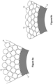
- the effect of the compacting apparatus 30 is shown schematically in the before-and-after drawings of Figures 6a and 6b . Its effect is to deform, radially compact and circumferentially spread the elements 16, hence packing them together closely into more intimate contact with each other to forming a thinner and denser agglomeration.
- An advantage of the invention is the ability to manufacture and install a complete infill structure for a PiP annulus in a continuous automated process, as exemplified above.
- the infill structure of the invention satisfies all functional requirements that would conventionally require separate thermal insulation and spacers, in particular, thermal management and resistance to radial compression.
- the infill structure of the invention also satisfies the requirement to locate auxiliary elements such as heating wires or fibre-optic cables within the annulus.
- the invention achieves these objectives by selecting different types of elongate elements 16 to be laid in a mixed bundle of parallel elements 16 and combining and positioning those elements 16 within the infill structure appropriately.
- Figures 7 and 8 illustrate some of the possibilities of this approach.
- a PiP assembly 32 of the invention comprises an inner pipe 12 spaced concentrically within an outer pipe 26, defining an annulus 34 between them.
- the annulus 34 contains an infill structure of the invention that comprises concentric layers, in this example four layers, containing various types of elongate elements 16.
- the outermost layer of elements 16 is spaced radially inwardly from the inner side of the outer pipe 26, leaving a radial, circumferentially-continuous gap 36 that interrupts conductive transmission of heat through the annulus 34.
- the inner side of the outer pipe 26 also has an optional low-friction coating 38 to ease insertion of the inner pipe 12 and the elements 16 into the outer pipe 26.
- neighbouring layers of elements 16 are mutually staggered circumferentially, thus aligning or nesting each element 16 of one layer angularly between elements 16 of the next layer.
- This enables successive layers to interlock for increased rigidity.
- the elements 16 increase slightly in diameter from layer to layer in radially outward sequence so that the elements 16 of all layers can bear against their neighbouring elements 16 in each layer without circumferential gaps between them.
- the elements 16 of the infill structure are primarily thermally insulating in their material(s) and/or their structure. Those insulating elements are designated 16A in Figure 7 . In several circumferential locations, the insulating elements 16A are stacked radially from the inner pipe 12 toward the outer pipe 26 through all layers of the infill structure. The stacked insulating elements 16A together form insulating regions 40 around the inner pipe 12.
- Some of the elements 16 of the infill structure are primarily mechanically resistant in their material(s) and/or their structure, at least with respect to radial compression. Those mechanically resistant, reinforcing elements are designated 16B in Figure 7 .
- the reinforcing elements 16B are grouped together in circumferential alignment to form discrete reinforcing formations, specifically spacer formations 42, that extend radially from the inner pipe 12 toward the outer pipe 26 through all layers of the infill structure.
- the spacer formations 42 are angularly spaced around the annulus 34, in this example at 60° intervals.
- the spacer formations 42 are stabilised by the abutment of the reinforcing elements 16B with the adjoining insulating elements 16A, hence being embedded by or between the insulating regions 40.
- the spacer formations 42 taper radially outwardly to form a stable structure that minimises the heat transmission path through the annulus 34.
- This taper can be achieved by reducing the number of reinforcing elements 16B moving outwardly through each spacer formation 38 from one layer to the next, here reducing from five such elements 16B in the innermost layer to two such elements 16B in the outermost layer.
- the example shown in Figure 7 also comprises auxiliary elements 16, in this case heating wires 16C and fibre-optic cables 16D.
- the heating wires 16C are grouped at equi-spaced angular locations within the insulating regions 40, alternating with the spacer formations 42.
- the heating wires 16C are part of the innermost layer of elements 16, hence being in thermal contact with the inner pipe 12. They are buried under one or more surrounding outer layers of insulating elements 16A.
- the fibre-optic cables 16D are positioned in an intermediate layer of the infill structure within the insulating regions 40, the better to sense conditions in the body of the annulus 34. To the benefit of thermal isolation, the fibre-optic cables 16D are also separated from the heating cables 16C, and from the heated inner pipe 12, by at least one insulating element 16A or by at least one layer of such elements 16A.
- the fibre-optic cables 16D are also equi-angularly spaced around the infill structure within the annulus 34, although this spacing is not essential. Also, some or all of the fibre-optic cables 16D could be replaced with other auxiliary elements 16 such as power cables or even fluid conduits.
- mechanically-reinforcing elements 16B could be positioned immediately adjacent to the heating wires 16C and/or the fibre-optic cables 16D to protect them and/or the thermally insulating elements 16A locally, depending on the materials and future operational utilisations of the PiP assembly 32 and the heating cables 16C.
- FIG 8 four mutually-staggered and hence interlocked layers of elements 16 are also shown in this example, like the arrangement in Figure 7 .
- the elements 16 are all of substantially equal diameter. Consequently, there are increasing circumferential gaps between the elements 16 of the second to fourth layers in radially outward sequence.
- the elements 16 of the first, innermost layer abut their neighbouring elements 16 in that layer.
- elements 16 of equal diameter could abut their neighbouring elements 16 in all layers if the number of elements in outer layers is increased to close circumferential gaps between them.
- Figure 8 exemplifies various possible configurations of the thermally insulating elements 16A and the mechanically-resistant reinforcing elements 16B. It does so in the context of a spacer formation 42.
- the spacer formation 38 is formed of two types of reinforcing elements 16B, namely thick-walled tubes 16B1, which could be made of extruded polymer or metal, and solid rods 16B2, which could be made of extruded polymer.
- the insulating elements 16A shown in Figure 8 are: hollow, gas-filled thin-walled tubes 16A1, which could be made of extruded polymer; thin-walled tubes 16A2, which could also be made of extruded polymer but are filled with thermal insulation material such as an aerogel; solid rods 16A3 of thermally insulating material such as a polymer foam; and elements 16A4 of a fibrous thermally insulating material such as a braid, a yarn or a rope.
- Figure 8 also shows the possibility that a spacer formation 42 could be formed of a hybrid or mixture of insulating elements 16A and reinforcing elements 16B.
- a core of insulating elements 16A1 lies within an outer wall of reinforcing elements 16B1 and 16B2, further to restrict heat transfer across the annulus 34.
- relative rotational movement between the pipeline 12 and the reels 18 of the winding machine 14 could instead, or additionally, be effected by turning the pipeline 12 about the central longitudinal axis 24.
- the pipeline 12 moves past stationary equipment comprising the reels 18, guides 20 and supports 22, it would be possible instead for that equipment to move past a stationary pipeline 12.
- the outer pipe 26 of a PiP arrangement it would be possible for the outer pipe 26 of a PiP arrangement to be advanced over a stationary pipeline 12, or to be assembled around the pipeline 12.
Landscapes
- Engineering & Computer Science (AREA)
- General Engineering & Computer Science (AREA)
- Mechanical Engineering (AREA)
- Thermal Insulation (AREA)
- Rigid Pipes And Flexible Pipes (AREA)
- Extrusion Moulding Of Plastics Or The Like (AREA)
Claims (21)
- Eine Rohr-in-Rohr-Anordnung (32), die Folgendes umfasst:eine gebündelte Füllungsstruktur, die einen Ringraum (34) zwischen innerem und äußerem Rohr (12, 26) der Anordnung (32) einnimmt, wobei die Füllungsstruktur aus einer Vielzahl von länglichen Elementen (16) gebildet ist, die entlang des inneren Rohrs (12) verlegt sind,wobei die länglichen Elemente (16) der Füllungsstruktur eine Mischung aus Verstärkungselementen (16B) und Isolationselementen (16A) umfasst, wobei die Verstärkungselemente (16B) einen größeren mechanischen Widerstand als die Isolationselemente (16A) gegenüber radialem Zusammendrücken aufweist, während die Isolationselemente (16A) eine größere thermische Isolation als die Verstärkungselemente (16B) bereitstellen; undwobei eine Vielzahl der Verstärkungselemente (16B) miteinander innerhalb der Füllungsstruktur positioniert sind, um Verstärkungsformationen zu bilden, die zwischen Isolationsregionen (40) der Füllungsstruktur eingebettet sind, die durch eine Vielzahl der Isolationselemente (16A) definiert sind, wobei die Verstärkungsformationen Abstandhalterformationen (42) sind, die winkelig um das innere Rohr (12) beabstandet sind und die sich radial von dem inneren Rohr (12) zu dem äußeren Rohr (26) erstrecken.
- Anordnung (32) nach Anspruch 1, wobei die Füllungsstruktur Lagen der länglichen Elemente (16) umfasst, die auf dem inneren Rohr (12) in einer Radial-nach-außen-Folge verlegt sind.
- Anordnung (32) nach Anspruch 2, wobei die länglichen Elemente (16) von jeder Lage winkelig relativ zu den länglichen Elementen (16) von jeder benachbarten Lage gestaffelt sind.
- Anordnung (32) nach Anspruch 2 oder Anspruch 3, wobei die Verstärkungsformationen weniger Verstärkungselemente (16B) in nachfolgenden Lagen einschließt, um sich in einer Radial-nach-außen-Richtung zuzuspitzen.
- Anordnung (32) nach einem vorhergehenden Anspruch, wobei die Abstandhalterformationen (42) jeweils eine Kombination aus den Verstärkungselementen (16B) und den Isolationselementen (16A) umfassen.
- Anordnung (32) nach einem vorhergehenden Anspruch, wobei die länglichen Elemente (16) der Füllungsstruktur ferner ein oder mehrere Hilfselemente umfassen, deren primärer Zweck darin liegt, das innere Rohr zu erwärmen oder elektrischen Strom oder Daten entlang der Anordnung zu transportieren.
- Anordnung (32) nach Anspruch 6, wobei ein oder mehrere der Hilfselemente ein Erwärmungselement (16C) ist/sind, das mit dem inneren Rohr (12) in thermischem Kontakt steht und von Isolationselementen (16A) der Füllungsstruktur umgeben ist.
- Anordnung (32) nach Anspruch 6 oder Anspruch 7, wobei ein oder mehrere der Hilfselemente ein Datenkabel (16D) ist/sind, das von dem inneren Rohr (12) und jedem Erwärmungselement (16C) durch mindestens ein Isolationselement (16A) oder Verstärkungselement (16B) der Füllungsstruktur getrennt ist.
- Anordnung (32) nach einem vorhergehenden Anspruch, wobei die länglichen Elemente (16) auf gegenseitig parallelen Pfaden liegen.
- Anordnung (32) nach einem vorhergehenden Anspruch, wobei die länglichen Elemente (16) auf spiralförmigen Pfaden liegen.
- Anordnung (32) nach einem vorhergehenden Anspruch, wobei die länglichen Elemente (16) eine Gruppe von Elementen umfassen, die miteinander verflochten, verstrickt, verwickelt, verdrillt, verklebt oder verschmolzen sind.
- Anordnung (32) nach einem vorhergehenden Anspruch, wobei die Isolationselemente (16A) Folgendes umfassen: hohle Röhren; mit thermisch isolierendem Material gefüllte Röhren; massive Stäbe aus thermisch isolierendem Material; oder Elemente aus einem faserigen thermisch isolierenden Material.
- Anordnung (32) nach Anspruch 12, wobei sowohl die Verstärkungselemente (16B) als auch die Isolationselemente (16A) röhrenförmig sind und die Röhren der Isolationselemente (16A) dünnere Wände als die Röhren der Verstärkungselemente (16B) aufweisen.
- Anordnung (32) nach einem vorhergehenden Anspruch, wobei sich die Verstärkungsformationen durch eine vollständige radiale Dicke der Füllungsstruktur erstrecken.
- Anordnung (32) nach einem vorhergehenden Anspruch, die einen umlaufend durchgehenden radialen Spalt zwischen der Füllungsstruktur und dem äußeren Rohr (26) umfasst.
- Ein Verfahren zum Herstellen einer Rohr-in-Rohr-Anordnung (32), wobei das Verfahren Folgendes umfasst:Bilden einer gebündelten Füllungsstruktur um ein inneres Rohr (12) der Anordnung (32) durch Verlegen einer Vielzahl von länglichen Elementen (16) entlang des inneren Rohrs (12); undEinführen des inneren Rohrs (12) und der Füllungsstruktur in ein äußeres Rohr (26) der Anordnung (32), wobei die Füllungsstruktur danach einen Ringraum (34) einnimmt, der zwischen dem inneren und äußeren Rohr (12, 26) definiert ist, wobeidie länglichen Elemente (16) der Füllungsstruktur eine Mischung aus Verstärkungselementen (16B) und Isolationselementen (16A) umfasst, wobei die Verstärkungselemente (16B) einen größeren mechanischen Widerstand als die Isolationselemente (16A) gegenüber radialem Zusammendrücken aufweist, während die Isolationselemente (16A) eine größere thermische Isolation als die Verstärkungselemente (16B) bereitstellen; unddie Verstärkungselemente (16B) miteinander innerhalb der Füllungsstruktur platziert sind, um Verstärkungsformationen zu bilden, wobei jede dieser Formationen eine Vielzahl der Verstärkungselemente (16B) umfasst und zwischen Isolationsregionen (40) der Füllungsstruktur eingebettet ist, die durch eine Vielzahl der Isolationselemente (16A) definiert sind, wobei die Verstärkungsformationen Abstandhalterformationen (42) sind, die winkelig um das innere Rohr (12) beabstandet sind und die sich radial von dem inneren Rohr (12) zu dem äußeren Rohr (26) erstrecken.
- Verfahren nach Anspruch 16, wobei die Füllungsstruktur Lagen der länglichen Elemente (16) umfasst, die auf dem inneren Rohr (12) in einer Radial-nach-außen-Folge verlegt sind.
- Verfahren nach Anspruch 17, wobei sich die Verstärkungsformationen in einer Radial-nach-außen-Richtung zuspitzen, indem weniger Verstärkungselemente (16B) in nachfolgenden Lagen eingeschlossen werden.
- Verfahren nach einem der Ansprüche 16 bis 18, wobei die länglichen Elemente der Füllungsstruktur ferner ein oder mehrere Hilfselemente umfassen, deren primärer Zweck darin liegt, Daten entlang der Anordnung zu transportieren, wobei das Verfahren das Verlegen von mindestens einem Datenkabel (16D) auf mindestens einer inneren Lage von länglichen Elementen (16) umfasst, die zwischen dem Datenkabel (16D) und dem inneren Rohr (12) angeordnet ist.
- Verfahren nach Anspruch 19, das das Verlegen der länglichen Elemente (16) auf dem inneren Rohr (12) umfasst, das von mindestens einer Rolle (18) einer Wickelmaschine (14) abgegeben wird.
- Verfahren nach einem der Ansprüche 16 bis 20, das das Kompaktieren der Füllungsstruktur durch Erwärmen und/oder Radial-nach-innen-Zusammendrücken vor dem Einführen des inneren Rohrs (12) und der Füllungsstruktur in das äußere Rohr (26) umfasst.
Applications Claiming Priority (2)
| Application Number | Priority Date | Filing Date | Title |
|---|---|---|---|
| GB2020303.0A GB2602161B (en) | 2020-12-21 | 2020-12-21 | Manufacture of pipe-in-pipe assemblies |
| PCT/IB2021/000902 WO2022136919A1 (en) | 2020-12-21 | 2021-12-20 | Manufacture of pipe-in-pipe assemblies |
Publications (2)
| Publication Number | Publication Date |
|---|---|
| EP4264098A1 EP4264098A1 (de) | 2023-10-25 |
| EP4264098B1 true EP4264098B1 (de) | 2024-12-11 |
Family
ID=74220998
Family Applications (1)
| Application Number | Title | Priority Date | Filing Date |
|---|---|---|---|
| EP21854815.4A Active EP4264098B1 (de) | 2020-12-21 | 2021-12-20 | Herstellung von rohr-in-rohr-anordnungen |
Country Status (5)
| Country | Link |
|---|---|
| US (1) | US20240044440A1 (de) |
| EP (1) | EP4264098B1 (de) |
| AU (1) | AU2021406120A1 (de) |
| GB (1) | GB2602161B (de) |
| WO (1) | WO2022136919A1 (de) |
Families Citing this family (1)
| Publication number | Priority date | Publication date | Assignee | Title |
|---|---|---|---|---|
| GB2628094A (en) | 2023-03-09 | 2024-09-18 | Acergy France SAS | Centralisers for pipeline assemblies |
Family Cites Families (10)
| Publication number | Priority date | Publication date | Assignee | Title |
|---|---|---|---|---|
| US3853149A (en) * | 1970-05-14 | 1974-12-10 | Moore & Co Samuel | Composite tubing |
| US6827110B2 (en) | 2002-01-07 | 2004-12-07 | Cuming Corporation | Subsea insulated pipeline with pre-cured syntactic elements and methods of manufacture |
| WO2004099554A2 (en) | 2003-05-06 | 2004-11-18 | Aspen Aerogels, Inc. | Load-bearing, lightweight, and compact insulation system |
| NO328774B1 (no) | 2008-10-06 | 2010-05-10 | Aker Subsea As | SZ-slagningsmaskin |
| FR2948164B1 (fr) | 2009-07-17 | 2011-06-24 | Technip France | Methode de fabrication de conduites tubulaires rigides a double enveloppe et installation dediee a la fabrication de ces conduites |
| US20130068340A1 (en) * | 2011-09-15 | 2013-03-21 | Tyco Thermal Controls, Llc | Heat trace system including hybrid composite insulation |
| US20140230946A1 (en) * | 2011-09-29 | 2014-08-21 | National Oilwell Varco Denmark I/S | Thermal insulating element, a subsea structure such as an armoured unbonded flexible pipe comprising such an element, and methods of manufacturing such an element and such a pipe |
| US9863571B2 (en) | 2015-12-21 | 2018-01-09 | Chevron U.S.A. Inc. | Apparatus, systems and methods for thermal management of subsea pipeline |
| FR3058842B1 (fr) | 2016-11-16 | 2020-11-06 | Saipem Sa | Machine pour la pose simultanee et en helice de cables sur la surface externe d'un element unitaire de conduite de transport de fluides |
| CN108758110B (zh) | 2018-06-14 | 2020-05-19 | 胜利油田兴达高祥新材料有限责任公司 | 天然气输送软管 |
-
2020
- 2020-12-21 GB GB2020303.0A patent/GB2602161B/en active Active
-
2021
- 2021-12-20 AU AU2021406120A patent/AU2021406120A1/en active Pending
- 2021-12-20 US US18/268,581 patent/US20240044440A1/en active Pending
- 2021-12-20 EP EP21854815.4A patent/EP4264098B1/de active Active
- 2021-12-20 WO PCT/IB2021/000902 patent/WO2022136919A1/en not_active Ceased
Also Published As
| Publication number | Publication date |
|---|---|
| WO2022136919A1 (en) | 2022-06-30 |
| GB2602161B (en) | 2023-05-24 |
| US20240044440A1 (en) | 2024-02-08 |
| AU2021406120A9 (en) | 2025-04-03 |
| EP4264098A1 (de) | 2023-10-25 |
| GB202020303D0 (en) | 2021-02-03 |
| GB2602161A (en) | 2022-06-22 |
| AU2021406120A1 (en) | 2023-07-06 |
Similar Documents
| Publication | Publication Date | Title |
|---|---|---|
| EP2122116B1 (de) | Energiekabel | |
| AU2016214075B2 (en) | Subsea pipe-in-pipe structures | |
| US8304651B2 (en) | Umbilical | |
| AU780741B2 (en) | Dynamic umbilicals with with internal steel rods | |
| CA2755289C (en) | Metal cord reinforced flexible pipe | |
| EP3259517B1 (de) | Unterwasser-rohr-in-rohr-strukturen | |
| NO20100926L (no) | Umbilical | |
| WO2018217119A1 (ru) | Полимерная армированная труба с электроподогревом | |
| EP4264098B1 (de) | Herstellung von rohr-in-rohr-anordnungen | |
| CN114467152A (zh) | 特别是用于井下用途的线缆以及制造这种线缆的方法 | |
| BR112015031062B1 (pt) | Método para fornecer um corpo compósito helicoidal | |
| GB2388641A (en) | A thermally insulated rigid pipe in pipe system and method | |
| CA3153250A1 (en) | Cables for cable deployed electric submersible pumps | |
| WO2020005074A1 (en) | Floating cable factory | |
| RU2745550C2 (ru) | Гибкая магистраль для транспортировки различных сред и труба для ее изготовления | |
| RU138537U1 (ru) | Гибкая труба (варианты) | |
| CN120809345B (zh) | 一种基于动态监测信息反馈的智能电缆及其制备方法 | |
| EP4355552B1 (de) | Herstellung von rohrleitungen | |
| JP5115770B2 (ja) | 超電導ケーブル |
Legal Events
| Date | Code | Title | Description |
|---|---|---|---|
| STAA | Information on the status of an ep patent application or granted ep patent |
Free format text: STATUS: UNKNOWN |
|
| STAA | Information on the status of an ep patent application or granted ep patent |
Free format text: STATUS: THE INTERNATIONAL PUBLICATION HAS BEEN MADE |
|
| PUAI | Public reference made under article 153(3) epc to a published international application that has entered the european phase |
Free format text: ORIGINAL CODE: 0009012 |
|
| STAA | Information on the status of an ep patent application or granted ep patent |
Free format text: STATUS: REQUEST FOR EXAMINATION WAS MADE |
|
| 17P | Request for examination filed |
Effective date: 20230720 |
|
| AK | Designated contracting states |
Kind code of ref document: A1 Designated state(s): AL AT BE BG CH CY CZ DE DK EE ES FI FR GB GR HR HU IE IS IT LI LT LU LV MC MK MT NL NO PL PT RO RS SE SI SK SM TR |
|
| DAV | Request for validation of the european patent (deleted) | ||
| DAX | Request for extension of the european patent (deleted) | ||
| GRAP | Despatch of communication of intention to grant a patent |
Free format text: ORIGINAL CODE: EPIDOSNIGR1 |
|
| STAA | Information on the status of an ep patent application or granted ep patent |
Free format text: STATUS: GRANT OF PATENT IS INTENDED |
|
| INTG | Intention to grant announced |
Effective date: 20240712 |
|
| P01 | Opt-out of the competence of the unified patent court (upc) registered |
Free format text: CASE NUMBER: APP_46586/2024 Effective date: 20240812 |
|
| GRAS | Grant fee paid |
Free format text: ORIGINAL CODE: EPIDOSNIGR3 |
|
| GRAA | (expected) grant |
Free format text: ORIGINAL CODE: 0009210 |
|
| STAA | Information on the status of an ep patent application or granted ep patent |
Free format text: STATUS: THE PATENT HAS BEEN GRANTED |
|
| AK | Designated contracting states |
Kind code of ref document: B1 Designated state(s): AL AT BE BG CH CY CZ DE DK EE ES FI FR GB GR HR HU IE IS IT LI LT LU LV MC MK MT NL NO PL PT RO RS SE SI SK SM TR |
|
| REG | Reference to a national code |
Ref country code: GB Ref legal event code: FG4D |
|
| REG | Reference to a national code |
Ref country code: CH Ref legal event code: EP |
|
| REG | Reference to a national code |
Ref country code: DE Ref legal event code: R096 Ref document number: 602021023388 Country of ref document: DE |
|
| REG | Reference to a national code |
Ref country code: IE Ref legal event code: FG4D |
|
| REG | Reference to a national code |
Ref country code: LT Ref legal event code: MG9D |
|
| PG25 | Lapsed in a contracting state [announced via postgrant information from national office to epo] |
Ref country code: HR Free format text: LAPSE BECAUSE OF FAILURE TO SUBMIT A TRANSLATION OF THE DESCRIPTION OR TO PAY THE FEE WITHIN THE PRESCRIBED TIME-LIMIT Effective date: 20241211 |
|
| PG25 | Lapsed in a contracting state [announced via postgrant information from national office to epo] |
Ref country code: FI Free format text: LAPSE BECAUSE OF FAILURE TO SUBMIT A TRANSLATION OF THE DESCRIPTION OR TO PAY THE FEE WITHIN THE PRESCRIBED TIME-LIMIT Effective date: 20241211 |
|
| PG25 | Lapsed in a contracting state [announced via postgrant information from national office to epo] |
Ref country code: BG Free format text: LAPSE BECAUSE OF FAILURE TO SUBMIT A TRANSLATION OF THE DESCRIPTION OR TO PAY THE FEE WITHIN THE PRESCRIBED TIME-LIMIT Effective date: 20241211 |
|
| REG | Reference to a national code |
Ref country code: NL Ref legal event code: MP Effective date: 20241211 |
|
| PG25 | Lapsed in a contracting state [announced via postgrant information from national office to epo] |
Ref country code: ES Free format text: LAPSE BECAUSE OF FAILURE TO SUBMIT A TRANSLATION OF THE DESCRIPTION OR TO PAY THE FEE WITHIN THE PRESCRIBED TIME-LIMIT Effective date: 20241211 |
|
| PG25 | Lapsed in a contracting state [announced via postgrant information from national office to epo] |
Ref country code: LV Free format text: LAPSE BECAUSE OF FAILURE TO SUBMIT A TRANSLATION OF THE DESCRIPTION OR TO PAY THE FEE WITHIN THE PRESCRIBED TIME-LIMIT Effective date: 20241211 Ref country code: GR Free format text: LAPSE BECAUSE OF FAILURE TO SUBMIT A TRANSLATION OF THE DESCRIPTION OR TO PAY THE FEE WITHIN THE PRESCRIBED TIME-LIMIT Effective date: 20250312 |
|
| PG25 | Lapsed in a contracting state [announced via postgrant information from national office to epo] |
Ref country code: IT Free format text: LAPSE BECAUSE OF NON-PAYMENT OF DUE FEES Effective date: 20241220 |
|
| PG25 | Lapsed in a contracting state [announced via postgrant information from national office to epo] |
Ref country code: RS Free format text: LAPSE BECAUSE OF FAILURE TO SUBMIT A TRANSLATION OF THE DESCRIPTION OR TO PAY THE FEE WITHIN THE PRESCRIBED TIME-LIMIT Effective date: 20250311 |
|
| PG25 | Lapsed in a contracting state [announced via postgrant information from national office to epo] |
Ref country code: NL Free format text: LAPSE BECAUSE OF FAILURE TO SUBMIT A TRANSLATION OF THE DESCRIPTION OR TO PAY THE FEE WITHIN THE PRESCRIBED TIME-LIMIT Effective date: 20241211 |
|
| REG | Reference to a national code |
Ref country code: AT Ref legal event code: MK05 Ref document number: 1750599 Country of ref document: AT Kind code of ref document: T Effective date: 20241211 |
|
| REG | Reference to a national code |
Ref country code: DE Ref legal event code: R119 Ref document number: 602021023388 Country of ref document: DE |
|
| PG25 | Lapsed in a contracting state [announced via postgrant information from national office to epo] |
Ref country code: SM Free format text: LAPSE BECAUSE OF FAILURE TO SUBMIT A TRANSLATION OF THE DESCRIPTION OR TO PAY THE FEE WITHIN THE PRESCRIBED TIME-LIMIT Effective date: 20241211 |
|
| PG25 | Lapsed in a contracting state [announced via postgrant information from national office to epo] |
Ref country code: PL Free format text: LAPSE BECAUSE OF FAILURE TO SUBMIT A TRANSLATION OF THE DESCRIPTION OR TO PAY THE FEE WITHIN THE PRESCRIBED TIME-LIMIT Effective date: 20241211 |
|
| PG25 | Lapsed in a contracting state [announced via postgrant information from national office to epo] |
Ref country code: IS Free format text: LAPSE BECAUSE OF FAILURE TO SUBMIT A TRANSLATION OF THE DESCRIPTION OR TO PAY THE FEE WITHIN THE PRESCRIBED TIME-LIMIT Effective date: 20250411 |
|
| PG25 | Lapsed in a contracting state [announced via postgrant information from national office to epo] |
Ref country code: PT Free format text: LAPSE BECAUSE OF FAILURE TO SUBMIT A TRANSLATION OF THE DESCRIPTION OR TO PAY THE FEE WITHIN THE PRESCRIBED TIME-LIMIT Effective date: 20250411 |
|
| PG25 | Lapsed in a contracting state [announced via postgrant information from national office to epo] |
Ref country code: EE Free format text: LAPSE BECAUSE OF FAILURE TO SUBMIT A TRANSLATION OF THE DESCRIPTION OR TO PAY THE FEE WITHIN THE PRESCRIBED TIME-LIMIT Effective date: 20241211 |
|
| PG25 | Lapsed in a contracting state [announced via postgrant information from national office to epo] |
Ref country code: AT Free format text: LAPSE BECAUSE OF FAILURE TO SUBMIT A TRANSLATION OF THE DESCRIPTION OR TO PAY THE FEE WITHIN THE PRESCRIBED TIME-LIMIT Effective date: 20241211 Ref country code: RO Free format text: LAPSE BECAUSE OF FAILURE TO SUBMIT A TRANSLATION OF THE DESCRIPTION OR TO PAY THE FEE WITHIN THE PRESCRIBED TIME-LIMIT Effective date: 20241211 |
|
| PG25 | Lapsed in a contracting state [announced via postgrant information from national office to epo] |
Ref country code: SK Free format text: LAPSE BECAUSE OF FAILURE TO SUBMIT A TRANSLATION OF THE DESCRIPTION OR TO PAY THE FEE WITHIN THE PRESCRIBED TIME-LIMIT Effective date: 20241211 |
|
| PG25 | Lapsed in a contracting state [announced via postgrant information from national office to epo] |
Ref country code: CZ Free format text: LAPSE BECAUSE OF FAILURE TO SUBMIT A TRANSLATION OF THE DESCRIPTION OR TO PAY THE FEE WITHIN THE PRESCRIBED TIME-LIMIT Effective date: 20241211 |
|
| REG | Reference to a national code |
Ref country code: CH Ref legal event code: PL |
|
| PG25 | Lapsed in a contracting state [announced via postgrant information from national office to epo] |
Ref country code: LU Free format text: LAPSE BECAUSE OF NON-PAYMENT OF DUE FEES Effective date: 20241220 |
|
| PG25 | Lapsed in a contracting state [announced via postgrant information from national office to epo] |
Ref country code: SE Free format text: LAPSE BECAUSE OF FAILURE TO SUBMIT A TRANSLATION OF THE DESCRIPTION OR TO PAY THE FEE WITHIN THE PRESCRIBED TIME-LIMIT Effective date: 20241211 |
|
| PG25 | Lapsed in a contracting state [announced via postgrant information from national office to epo] |
Ref country code: MC Free format text: LAPSE BECAUSE OF FAILURE TO SUBMIT A TRANSLATION OF THE DESCRIPTION OR TO PAY THE FEE WITHIN THE PRESCRIBED TIME-LIMIT Effective date: 20241211 |
|
| REG | Reference to a national code |
Ref country code: BE Ref legal event code: MM Effective date: 20241231 |
|
| PG25 | Lapsed in a contracting state [announced via postgrant information from national office to epo] |
Ref country code: DE Free format text: LAPSE BECAUSE OF NON-PAYMENT OF DUE FEES Effective date: 20250701 Ref country code: DK Free format text: LAPSE BECAUSE OF FAILURE TO SUBMIT A TRANSLATION OF THE DESCRIPTION OR TO PAY THE FEE WITHIN THE PRESCRIBED TIME-LIMIT Effective date: 20241211 |
|
| PG25 | Lapsed in a contracting state [announced via postgrant information from national office to epo] |
Ref country code: BE Free format text: LAPSE BECAUSE OF NON-PAYMENT OF DUE FEES Effective date: 20241231 |
|
| PLBE | No opposition filed within time limit |
Free format text: ORIGINAL CODE: 0009261 |
|
| STAA | Information on the status of an ep patent application or granted ep patent |
Free format text: STATUS: NO OPPOSITION FILED WITHIN TIME LIMIT |
|
| PG25 | Lapsed in a contracting state [announced via postgrant information from national office to epo] |
Ref country code: CH Free format text: LAPSE BECAUSE OF NON-PAYMENT OF DUE FEES Effective date: 20241231 |
|
| PG25 | Lapsed in a contracting state [announced via postgrant information from national office to epo] |
Ref country code: IE Free format text: LAPSE BECAUSE OF NON-PAYMENT OF DUE FEES Effective date: 20241220 |
|
| 26N | No opposition filed |
Effective date: 20250912 |
|
| PGFP | Annual fee paid to national office [announced via postgrant information from national office to epo] |
Ref country code: GB Payment date: 20251229 Year of fee payment: 5 |
|
| PGFP | Annual fee paid to national office [announced via postgrant information from national office to epo] |
Ref country code: NO Payment date: 20251216 Year of fee payment: 5 |
|
| PG25 | Lapsed in a contracting state [announced via postgrant information from national office to epo] |
Ref country code: IT Free format text: LAPSE BECAUSE OF NON-PAYMENT OF DUE FEES Effective date: 20241220 |
|
| PGFP | Annual fee paid to national office [announced via postgrant information from national office to epo] |
Ref country code: IT Payment date: 20241231 Year of fee payment: 4 |
|
| PGRI | Patent reinstated in contracting state [announced from national office to epo] |
Ref country code: IT Effective date: 20241231 |
|
| PGFP | Annual fee paid to national office [announced via postgrant information from national office to epo] |
Ref country code: FR Payment date: 20251217 Year of fee payment: 5 |