EP4263387B1 - Behälter mit schachtel und hülse mit manipulationssicherem mechanismus - Google Patents
Behälter mit schachtel und hülse mit manipulationssicherem mechanismus Download PDFInfo
- Publication number
- EP4263387B1 EP4263387B1 EP21836462.8A EP21836462A EP4263387B1 EP 4263387 B1 EP4263387 B1 EP 4263387B1 EP 21836462 A EP21836462 A EP 21836462A EP 4263387 B1 EP4263387 B1 EP 4263387B1
- Authority
- EP
- European Patent Office
- Prior art keywords
- panel
- outer sleeve
- inner slide
- slide
- cover
- Prior art date
- Legal status (The legal status is an assumption and is not a legal conclusion. Google has not performed a legal analysis and makes no representation as to the accuracy of the status listed.)
- Active
Links
Images


Classifications
-
- B—PERFORMING OPERATIONS; TRANSPORTING
- B65—CONVEYING; PACKING; STORING; HANDLING THIN OR FILAMENTARY MATERIAL
- B65D—CONTAINERS FOR STORAGE OR TRANSPORT OF ARTICLES OR MATERIALS, e.g. BAGS, BARRELS, BOTTLES, BOXES, CANS, CARTONS, CRATES, DRUMS, JARS, TANKS, HOPPERS, FORWARDING CONTAINERS; ACCESSORIES, CLOSURES, OR FITTINGS THEREFOR; PACKAGING ELEMENTS; PACKAGES
- B65D85/00—Containers, packaging elements or packages, specially adapted for particular articles or materials
- B65D85/07—Containers, packaging elements or packages, specially adapted for particular articles or materials for compressible or flexible articles
- B65D85/08—Containers, packaging elements or packages, specially adapted for particular articles or materials for compressible or flexible articles rod-shaped or tubular
- B65D85/10—Containers, packaging elements or packages, specially adapted for particular articles or materials for compressible or flexible articles rod-shaped or tubular for cigarettes
- B65D85/1036—Containers formed by erecting a rigid or semi-rigid blank
-
- B—PERFORMING OPERATIONS; TRANSPORTING
- B65—CONVEYING; PACKING; STORING; HANDLING THIN OR FILAMENTARY MATERIAL
- B65D—CONTAINERS FOR STORAGE OR TRANSPORT OF ARTICLES OR MATERIALS, e.g. BAGS, BARRELS, BOTTLES, BOXES, CANS, CARTONS, CRATES, DRUMS, JARS, TANKS, HOPPERS, FORWARDING CONTAINERS; ACCESSORIES, CLOSURES, OR FITTINGS THEREFOR; PACKAGING ELEMENTS; PACKAGES
- B65D5/00—Rigid or semi-rigid containers of polygonal cross-section, e.g. boxes, cartons or trays, formed by folding or erecting one or more blanks made of paper
- B65D5/38—Drawer-and-shell type containers
-
- B—PERFORMING OPERATIONS; TRANSPORTING
- B65—CONVEYING; PACKING; STORING; HANDLING THIN OR FILAMENTARY MATERIAL
- B65D—CONTAINERS FOR STORAGE OR TRANSPORT OF ARTICLES OR MATERIALS, e.g. BAGS, BARRELS, BOTTLES, BOXES, CANS, CARTONS, CRATES, DRUMS, JARS, TANKS, HOPPERS, FORWARDING CONTAINERS; ACCESSORIES, CLOSURES, OR FITTINGS THEREFOR; PACKAGING ELEMENTS; PACKAGES
- B65D5/00—Rigid or semi-rigid containers of polygonal cross-section, e.g. boxes, cartons or trays, formed by folding or erecting one or more blanks made of paper
- B65D5/42—Details of containers or of foldable or erectable container blanks
- B65D5/54—Lines of weakness to facilitate opening of container or dividing it into separate parts by cutting or tearing
- B65D5/5405—Lines of weakness to facilitate opening of container or dividing it into separate parts by cutting or tearing for opening containers formed by erecting a blank in tubular form
- B65D5/541—Lines of weakness to facilitate opening of container or dividing it into separate parts by cutting or tearing for opening containers formed by erecting a blank in tubular form the lines of weakness being provided in one or more closure flaps
Definitions
- the present invention relates to a novel container, which finds particular application as a container for consumer goods, such as elongate aerosol-generating articles and components of aerosol generating articles.
- elongate smoking articles such as cigarettes and cigars
- rigid box shaped containers such as hinged lid containers having a box portion and a three-dimensional cup shaped hinge lid connected to the box about a hinge line extending across the back wall of the container.
- the lid is pivoted about the hinge line to open the pack and so gain access to the consumer goods held in the box.
- DE 2538845 A1 describes a container with an outer sleeve and an inner slide.
- the inner slide and the outer sleeve are at least initially detachably connected with each other by way of a detachable tear strip.
- the tear strip is joined with the inner slide and the outer sleeve by way of lines of weakness provided at opposed edges of the tear strip. As such, the inner slide and the outer sleeve are separable from each other after the tear strip is removed along the lines of weakness.
- Containers with arrangements for preventing an inner slide from being completely removed from a an outer sleeve are known from WO 2009/101071 A1 and WO 2011/1154822 A1 .
- GB 264689 A describes an example of a slide-and-shell container wherein a front wall of the outer shell comprises a line of weakness delimiting a portion of the front wall that can be detached from the remainder of the front wall, so that a cut out is formed at the front of the container. This is to facilitate opening of the container, as the consumer's thumb can access the inner slide through the cut out formed at the front of the container.
- reclosable containers It is generally desirable to improve the ease of use of reclosable containers. It is also desirable to be able to equip a reclosable container for consumer goods with tamper-evident means that allow a consumer to detect whether the content has been accessed before.
- a container for consumer goods comprising: an outer sleeve comprising an outer sleeve front wall, an outer sleeve back wall, first and second opposed outer sleeve side walls; an inner slide mounted within the outer sleeve, the inner slide comprising an inner slide bottom wall, an inner slide front wall, and an inner slide back wall, and a sleeve cover comprising a sleeve cover first panel and a sleeve cover second panel, the sleeve cover first panel detachably depending from the outer sleeve along a first line of weakness and extending between the outer sleeve back wall and the outer sleeve front wall, the sleeve cover second panel detachably depending from the sleeve cover first panel along a second line of weakness and permanently affixed to an inner surface of the outer sleeve, such that upon separation of the first panel from the outer sleeve and the second
- the terms “front”, “back”, “upper”, “lower”, “top”, “bottom” and “side”, refer to the relative positions of portions of containers according to the invention and components thereof when the container is in an upright position. When describing containers according to the present invention, these terms are used irrespective of the orientation of the container being described.
- the front wall of the container is the wall of the outer sleeve to which the second panel of the anti-tamper cover is permanently affixed, such as by means of permanent adhesive.
- line of weakness is used in the present specification to refer to a line on a sheet of material, such as paper or cardboard, along which the material has been weakened, such as through removal of some of the material along that line (for example by scoring) or by folding or creasing the sheet material along that line. This facilitates the tearing or breakage of the sheet material along a desired line.
- a line of weakness may also be provided as a line of perforations or slits or cuts.
- the line of weakness may be provided as a separation line having slits or cuts arranged at predetermined intervals and separated by ties, such that separating portions of the container depending from one another along the separation lines, a relatively small number (for example 2 to 10) of ties needs to be broken.
- the present invention relates to a slide-and-sleeve container.
- the outer sleeve comprises an outer sleeve front wall, an outer sleeve back wall, first and second opposed outer sleeve side walls.
- the inner slide is mounted within the outer sleeve, and comprises an inner slide bottom wall, an inner slide front wall, and an inner slide back wall.
- a container in accordance with the present invention comprises a sleeve cover comprising a sleeve cover first panel and a sleeve cover second panel, wherein the sleeve cover first panel - which extends between the outer sleeve back wall and the outer sleeve front wall - depends detachably from the outer sleeve along a first line of weakness.
- the sleeve cover second panel depends detachably from the first panel along a second line of weakness, and the sleeve cover second panel is permanently affixed to an inner surface of the outer sleeve.
- a first outer sleeve opening is revealed at a top end of the outer sleeve.
- the inner slide becomes movable within the outer sleeve between a fully inserted position, wherein the inner slide fully rests within the outer sleeve, and a protruding position wherein the inner slide extends at least partly outside of the outer sleeve through the outer sleeve opening.
- a top edge of the inner slide front wall is configured to engage with a corresponding bottom edge of the sleeve cover second panel to prevent the inner slide from being removed from the outer sleeve through the first outer sleeve opening.
- the detachable first panel of the sleeve cover provides an anti-tamper feature. This is desirable, as it may promptly alert a consumer to the fact that consumer goods within the container may have been accessed before.
- the container of the invention may comprise a locking mechanism that advantageously helps control movement of the inner slide within the outer sleeve during use. This is desirable in that it enables easy and reliable access to the content of the inner sleeve.
- other components of the container may also be configured to cooperate in order to more thoroughly control and guide movement of the inner slide within the outer sleeve, such as to further enhance ease of use of the container.
- the outer sleeve further comprises one or more locking panels affixed to an inner surface of at least one of the outer sleeve front wall, the outer sleeve back wall and the outer sleeve side walls, wherein a top edge of the one or more locking panels is configured to engage with a corresponding edge of the inner slide bottom wall when the inner slide is in the fully inserted position to prevent the inner slide from being detached from the outer sleeve through a second outer sleeve opening at a bottom end of the outer sleeve.
- a second locking mechanism at the bottom of the container, linear movement of the slide within the sleeve is advantageously limited at two ends. This further facilitates use of the container and desirably prevents the inner slide from being pushed too far and being removed from the outer sleeve.
- the inner slide further comprises a slide cover comprising a top panel depending from the inner slide back wall along a top edge of the inner slide back wall, the slide cover top panel being pivotable about the top edge of the inner slide back wall between a slide cover closed position and a slide cover open position to reveal a content of the inner slide.
- an inner slide cover advantageously provides a further degree of protection for the consumer goods within the inner slide.
- the consumer has not only to detach the first panel of the sleeve cover from the outer sleeve, but also to move the slide cover top panel from its closed position to its open position.
- the slide cover top panel is configured to engage with the sleeve cover second panel when the inner slide is in the fully inserted slide position to secure the slide cover in the slide cover closed position. This is advantageous in that it ensures that between consecutive accesses the remaining consumer goods are held securely within the inner slide.
- the slide cover top panel comprises a lock tab configured to engage with a cut out formed in the bottom edge of the sleeve cover second panel. This provides for a secure and reliable engagement between the slide cover panel and the bottom edge of the second panel. Thus, between consecutive accesses the remaining consumer goods are held within the inner slide in a particularly stable and secure manner.
- cooperation between the lock tab of the slide cover top panel with the cut out in the bottom edge of the sleeve cover second panel produces a click-like sound.
- this may provide the user with an auditory cue confirming that closure of the container has been secured between uses.
- a recess is defined within the outer shell above the slide cover panel.
- the first panel of the sleeve cover detachably depends from the outer sleeve back wall along the first line of weakness
- the sleeve cover further comprises a line of weakness at least partially extending across the first panel between the outer sleeve back wall and the sleeve cover second panel to define a pull tab at one end of the first panel for facilitating separation of the sleeve cover first panel from the outer sleeve and from the sleeve cover second panel along the first and second separation lines, respectively.
- the provision of one such tab is advantageous as, upon opening the container for the first time, the pull tab principally acts as a handle.
- the pull tab is defined at one end of the sleeve cover first panel, the consumer is thus guided to apply the required tearing force along the most favourable direction, which may facilitate the opening operation and reduce the likelihood of breakages.
- the inner slide comprises a line of weakness extending across the inner slide back wall and dividing the inner slide back wall into a slide back wall bottom panel extending below the line of weakness and a slide back wall top panel extending above the line of weakness, wherein when the inner slide is in the protruding position the inner slide back wall top panel is configured to be pivotable along the line of weakness over a top edge of the outer sleeve back wall to facilitate access to a content of the inner sleeve.
- the provision of one such line of weakness has the advantage that, when the inner slide is moved into the protruding position, the slide back wall top panel can be pivoted backwards, which may make it easier for the consumer to extract the consumer goods from the top of the container.
- an inner package containing the consumer goods is received within the inner slide and wherein the inner package comprises a tear tape extending 360 degrees around the inner package at a location towards a top of the inner package.
- a container in accordance with the present invention finds use as a container for consumer goods, and may be used in particular for holding aerosol-generating articles, as will be described in more detail below.
- the container comprises a group of consumer goods wrapped in an inner package, the inner package being received within and secured to the inner slide such that the inner package moves integral with the inner slide when the inner slide is moved between the fully inserted slide position and the protruding slide position.
- This is beneficial in that the consumer can easily and directly control the position of the inner package within the container by moving the slide between the fully inserted position and the protruding position.
- the inner package may be secured to a surface of the inner slide by providing permanent adhesive between the outer surface of the inner package and the surface of the inner slide.
- a single dot of a permanent glue may be sufficient to this purpose.
- the inner package is sealed. This is beneficial for preserving the characteristics of the consumer goods within the container. Further, it combines with the provision of the sleeve cover to provide the consumer with a clear indication of whether the consumer goods within the container have been accessed before.
- the term "sealed" is used to indicate that the inner package has been formed by wrapping a typically rectangular blank of air-impermeable packaging material about a group of consumer goods, and seals have been formed between overlapping edge portions of the blank.
- a fin seal is formed on each longitudinal side of the inner package.
- an access opening is typically provided to enable access to and extraction of the consumer goods.
- the opening In a "sealed" inner package, the opening only becomes accessible when the package is opened for the first time.
- the inner package further comprises a resealable label hermetically occluding the access opening.
- the provision of one such label has the advantage that the inner package can not only be reclosed, but also substantially resealed between subsequent accesses to the content of the inner package.
- one such label may include a tab by which the user can conveniently handle the label to move it between respective closed and open positions, as will also be described in greater detail below.
- an access opening may only be predefined, such as for example by the provision of lines of weakness in the inner package, yet the opening only effectively becomes accessible when the continuity of the material of the blank is interrupted along the lines of weakness when the user opens the inner package for the first time.
- the inner package comprises a tear tape for facilitating opening of the inner package and extraction of the consumer goods from the inner package. This ensures an easy and controlled first opening of the inner package and may help preserve a predefined portion of the inner package after the first opening of the container. The preserved remaining portion of the inner package advantageously protects the consumer goods.
- the inner package is resealable and comprises an access opening for extracting the consumer goods from the inner package, and a resealable adhesive label extending over the access opening and movable between a closed position, wherein the resealable adhesive label occludes the access opening, and an open position, wherein the resealable adhesive is at least partially lifted off a surface of the inner package to reveal the access opening.
- one or more lines of weakness may be formed on the inner package to define the access opening.
- lines of weakness extending over the front wall of the inner package or the top wall of the inner package or both may at least partly delimit a portion of the inner package that can move between respective closed and open positions. When the portion of inner package delimited by the lines of weakness is lifted, the access opening is revealed.
- a permanent connection is established between such portion of the inner package delimited by the lines of weakness and the resealable adhesive label.
- This may be achieved by providing permanent adhesive between an area of the inner surface of the resealable adhesive label and the underlying portion of the inner package delimited by the lines of weakness.
- movement of the resealable adhesive label between its closed and open positions causes the portion of the inner package to move integrally with the resealable adhesive label between its respective closed and open position.
- the inner slide further comprises a protective panel that depends from the top panel of the inner slide cover along a fold line defining a front edge of the inner slide cover top panel.
- the protective panel is pivotable about the fold line between a protective panel closed position and a protective panel open position. In the protective panel closed position, the protective panel is substantially parallel to the outer sleeve front wall.
- the protective panel closed position In practice, when an inner package is received within the inner slide, in the protective panel closed position the protective panel may come to rest against a front wall of the inner package. To move into the protective panel open position, the protective panel is tilted forwards and upwards to reveal an interior of the inner slide. In practice, when an inner package is received within the inner slide, to reach the protective panel open position the protective panel may be moved away from a front wall of the inner package to reveal the access opening in the inner package.
- the protective panel contributes to the overall structural strength of the container and, in particular, of the inner slide. Further, the protective panel substantially hides and contributes to preventing access to the content of inner package between uses.
- a resealable adhesive label that extends over the access opening, to access the consumer goods within the container a user needs to lift the inner slide containing the package to protrude out of the outer sleeve, move the protective panel into its open position and subsequently peel the resealable adhesive label from the label closed position to and the label open position.
- the protective panel provides an additional level of security.
- the resealable adhesive label is permanently affixed to an inner surface of the protective panel, such that that movement of the protective panel between the protective panel closed position and the protective panel open position causes the resealable adhesive label to move between the label closed position and open position to reveal to access opening.
- the protective panel may have a larger surface area and be made of a thicker and more rigid material, which may facilitate handling for the user.
- the resealable adhesive label is controlled indirectly via movement of the protective panel, and the protective panel is bound by its geometry and structure to move in a finely predetermined way, in these embodiments it is advantageously possible to achieve a particularly smooth and controlled peeling of the resealable adhesive label from the inner package. This is desirable in that it may help preserve the integrity and stability of the opening/closing mechanism. Further, as the user does not handle directly the resealable adhesive label, it may be easier to prevent the label from becoming accidentally stuck to itself or to other portions of the container during use.
- a permanent adhesive may for example be provided between an area on the outer surface of the resealable adhesive label and a corresponding area on the inner surface of the protective panel.
- the inner package comprises an inner frame arranged within the inner package to hold the group of consumer goods in a defined collation pattern.
- the provision of one such inner frame increases the structural strength of the container and provides a further protection for the consumer goods within the inner package. Further, the provision of one such inner frame helps the inner package maintain its original shape even after a number of the consumer goods originally contained in the inner package have been extracted from the container. This has the benefit of facilitating smooth and reliable movement of the inner slide with the inner package between the fully inserted position and the protruding position.
- the size of the various components of a container in accordance with the invention will be a function of the size and number of the consumer goods destined to be held within the container.
- a difference between a height of the outer sleeve and a height of the inner package may be at least 5 millimetres. In certain preferred embodiments, a difference between a height of the outer sleeve and a height of the inner package is at least 8 millimetres. More preferably, a difference between a height of the outer sleeve and a height of the inner package is at least 10 millimetres.
- the inventors have observed that in containers wherein a difference between a height of the outer sleeve and a height of the inner package falls within such ranges, it may be easier to ensure that the inner slide and the outer sleeve cooperate as described above, such that the inner slide is efficiently prevented from sliding out of the outer sleeve in its entirety.
- a height of the inner slide front wall is less than or equal to 50 percent of a height of the inner package. More preferably, a height of the inner slide front wall is less than or equal to 45 percent of a height of the inner package. Even more preferably, a height of the inner slide front wall is less than or equal to 40 percent of a height of the inner package.
- a height of the inner slide front wall is at least 20 percent of a height of the inner package. More preferably, a height of the inner slide front wall is at least 25 percent of a height of the inner package. Even more preferably, a height of the inner slide front wall is at least 30 percent of a height of the inner package.
- a height of the inner slide front wall is from 20 percent of a height of the inner package to 50 percent of a height of the inner package, preferably from 25 percent of a height of the inner package to 50 percent of a height of the inner package, more preferably from 30 percent of a height of the inner package to 50 percent of a height of the inner package.
- a height of the inner slide front wall is from 20 percent of a height of the inner package to 45 percent of a height of the inner package, preferably from 25 percent of a height of the inner package to 45 percent of a height of the inner package, more preferably from 30 percent of a height of the inner package to 45 percent of a height of the inner package.
- a height of the inner slide front wall is from 20 percent of a height of the inner package to 40 percent of a height of the inner package, preferably from 25 percent of a height of the inner package to 40 percent of a height of the inner package, more preferably from 30 percent of a height of the inner package to 40 percent of a height of the inner package.
- a height of the inner slide front wall is from 30 percent of a height of the inner package to 35 percent of a height of the inner package, for example 33 percent of a height of the inner package.
- the ratio between a height of the inner slide front wall and a height of the inner package substantially impacts an operative length over which the inner slide can move within the outer sleeve between the fully inserted position and the protruding position.
- a height of the inner slide front wall is less than 40 percent of a height of the sleeve. More preferably, a height of the inner slide front wall is less than 35 percent of a height of the sleeve. Even more preferably, a height of the inner slide front wall is less than 30 percent of a height of the sleeve.
- a height of the inner slide front wall is at least 15 percent of a height of the sleeve. More preferably, a height of the inner slide front wall is at least 20 percent of a height of the sleeve. Even more preferably, a height of the inner slide front wall is at least 25 percent of a height of the sleeve.
- a height of the inner slide front wall is from 15 percent of a height of the sleeve to 40 percent of a height of the sleeve, preferably from 20 percent of a height of the sleeve to 40 percent of a height of the sleeve, more preferably from 25 percent of a height of the sleeve to 35 percent of a height of the sleeve.
- a height of the inner slide front wall is from 15 percent of a height of the sleeve to 35 percent of a height of the sleeve, preferably from 20 percent of a height of the sleeve to 40 percent of a height of the sleeve, more preferably from 25 percent of a height of the sleeve to 35 percent of a height of the sleeve.
- a height of the inner slide front wall is from 15 percent of a height of the sleeve to 30 percent of a height of the sleeve, preferably from 20 percent of a height of the sleeve to 30 percent of a height of the sleeve, more preferably from 25 percent of a height of the sleeve to 30 percent of a height of the sleeve.
- the outer sleeve comprises one or more locking panels affixed to an inner surface of at least one of the outer sleeve front wall, the outer sleeve back wall and the outer sleeve side walls, as described above, the one or more locking panels preferably comprise a front locking panel affixed to an inner surface of the outer sleeve front wall.
- a height of the inner slide front wall is less than 55 percent of a distance between the bottom edge of the second panel and the top edge of the front locking panel. More preferably, a height of the inner slide front wall is less than 50 percent of a distance between the bottom edge of the second panel and the top edge of the front locking panel. Even more preferably, a height of the inner slide front wall is less than 45 percent of a distance between the bottom edge of the second panel and the top edge of the front locking panel.
- a height of the inner slide front wall is at least 25 percent of a distance between the bottom edge of the second panel and the top edge of the front locking panel. More preferably, a height of the inner slide front wall is at least 30 percent of a distance between the bottom edge of the second panel and the top edge of the front locking panel. Even more preferably, a height of the inner slide front wall is at least 35 percent of a distance between the bottom edge of the second panel and the top edge of the front locking panel.
- a height of the inner slide front wall is from 25 percent to 55 percent of a distance between the bottom edge of the second panel and the top edge of the front locking panel, more preferably from 30 percent to 55 percent of a distance between the bottom edge of the second panel and the top edge of the front locking panel, even more preferably from 35 percent to 55 percent of a distance between the bottom edge of the second panel and the top edge of the front locking panel.
- a height of the inner slide front wall is from 25 percent to 50 percent of a distance between the bottom edge of the second panel and the top edge of the front locking panel, more preferably from 30 percent to 50 percent of a distance between the bottom edge of the second panel and the top edge of the front locking panel, even more preferably from 35 percent to 50 percent of a distance between the bottom edge of the second panel and the top edge of the front locking panel.
- a height of the inner slide front wall is from 25 percent to 45 percent of a distance between the bottom edge of the second panel and the top edge of the front locking panel, more preferably from 30 percent to 45 percent of a distance between the bottom edge of the second panel and the top edge of the front locking panel, even more preferably from 35 percent to 45 percent of a distance between the bottom edge of the second panel and the top edge of the front locking panel.
- the inner slide further comprises first and second opposed inner slide side walls.
- Containers according to the invention are preferably formed from one or more folded laminar blanks.
- the one or more laminar blanks may be formed from any suitable material or combination of materials including, but not limited to, cardboard, paperboard, plastic, metal, or combinations thereof.
- the different components of the container may be formed from the same material, or from different materials.
- Each of the one or more laminar blanks may be laminar cardboard blank having a weight of between about 100 grams per square metre and about 350 grams per square metre.
- the blank has a thickness of from about 100 micrometres to about 500 micrometres, preferably from about 200 micrometres to about 350 micrometres.
- the container is preferably a rectangular parallelepiped comprising two wider walls (front and back) spaced apart by two narrower side walls.
- Containers according to the invention may be in the shape of a rectangular parallelepiped, with right-angled longitudinal and right-angled transverse edges.
- the container may comprise one or more rounded longitudinal edges, rounded transverse edges, bevelled longitudinal edges or bevelled transverse edges, or combinations thereof.
- the container may comprise a plurality of consumer goods received within the inner slide.
- the consumer goods may be aerosol-generating articles.
- the aerosol-generating articles may be filter cigarettes or other smoking articles in which an aerosol-generating substrate comprises a tobacco material that is combusted to form smoke.
- the aerosol-generating articles may be articles in which a tobacco material is heated to form an aerosol, rather than combusted.
- the aerosol-generating articles may be articles in which a nicotine-containing aerosol is generated from a tobacco material, tobacco extract, or other nicotine source, without combustion, and in some cases without heating, for example through a chemical reaction.
- the aerosol-generating articles may be provided within the container in the form of a bundle wrapped in an inner package formed of metal foil or metallised paper.
- the inner package material may be formed as a laminate of a metallised polyethylene film, and a liner material.
- the liner material may be a super-calendered glassine paper.
- the inner package material may be provided with a print-receptive top coating.
- the inner package has an access opening through which aerosol-generating articles can be removed when the lid of the container is in a respective open position.
- containers according to the invention may be designed to hold different total numbers of aerosol-generating articles, or different arrangements of aerosol-generating articles.
- containers according to the invention may be designed to hold a total of between ten and thirty aerosol-generating articles, such as smoking articles.
- the aerosol-generating articles may be arranged in different collations, depending on the total number.
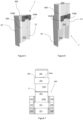
- Figure 1 shows two laminar blanks for forming a container 1 according to the present invention, namely a first laminar blank 100 and a second laminar blank 200.
- the laminar blanks can be used to form a container 1 as shown in Figures 2 to 6 .
- the first laminar blank 100 is configured to form an outer sleeve 10 of the container 1.
- the first laminar blank 100 comprises an outer sleeve front wall panel 151, an outer sleeve back wall panel 152, first and second outer sleeve side wall panels 153, 154.
- the first laminar blank 100 comprises a sleeve cover first panel 155 and a sleeve cover second panel 156.
- the sleeve cover first panel 155 depends along a line of weakness A from the outer sleeve back wall panel 152.
- the sleeve cover second panel 156 depends along a line of weakness B from the sleeve cover first panel 155.
- the sleeve cover first panel 155 is detachable from both the outer sleeve back wall panel 152 and the sleeve cover second panel 156.
- the sleeve cover first panel 155 comprises a line of weakness C extending across the sleeve cover first panel 155 between the outer sleeve back wall panel 152 and the sleeve cover second panel 156 to define a pull tab 155A at one end of the sleeve cover first panel 155.
- a cut out 156A is formed in the sleeve cover second panel 156 on the side opposite the sleeve cover first panel 155.
- two tabs 156B are defined in the sleeve cover second panel 156 on opposite sides of the cut out 156A.
- the first laminar blank 100 also includes a panel 157 depending along a fold line from the outer sleeve front wall panel 151 for forming an outer sleeve side flap.
- the outer sleeve side flap 157 is affixed by permanent adhesive (indicated by the cross hatching in the drawing of Figure 1 ) to the first outer sleeve wall panel 153.
- the first laminar blank 100 also includes panels 158, 159, 160, 161 for forming outer sleeve locking panels.
- the panels 158, 159, 160, 161 are folded by 180 degrees and affixed by permanent adhesive indicated by the cross hatching in the drawing of Figure 1 ) to panels 151, 152, 153, 154, respectively.
- the second laminar blank 200 is configured to form an inner slide 12 of the container 1.
- the second laminar blank 200 comprises an inner slide bottom wall panel 251, an inner slide front wall panel 252, an inner slide back wall panel 253, and an inner slide cover panel 254.
- the second laminar blank 200 further comprises inner slide side wall panels 255, 256, which depend along respective fold lines from the inner slide back wall panel 253, as well as dust flaps 257, 258, which depend along respective fold lines from the inner slide side wall panels 255, 256.
- the inner slide back wall panel 253 comprises a line of weakness D extending across the inner slide back wall panel 253 and dividing the inner slide back wall panel into a slide back wall bottom panel 253B extending below the line of weakness D and a slide back wall top panel 253T extending above the line of weakness D.
- the inner slide cover panel 254 comprises a lock tab 254A on the side opposite the inner slide back wall panel 253.
- the second laminar blank 200 comprises side panels 259, 260 depending along respective fold lines from the inner slide front wall panel 252 for forming inner slide side flaps.
- the inner slide side flaps 259, 260 are affixed by permanent adhesive (indicated by the cross hatching in the drawing of Figure 1 ) to the inner slide side wall panels 255, 256.
- a group of consumer goods for example, a bundle of aerosol-generating article arranged in accordance with a predetermined collation - is partially circumscribed by a reinforcing inner frame and wrapped within a flexible liner to form an inner package.
- the inner liner may be sealed by means of seals formed as fin seals.
- a tear tape is applied on the inside of the flexible liner for ease of opening.
- the laminar blank 200 for forming the inner slide is wrapped and folded around the thus formed package.
- the laminar blank 100 for forming the outer sleeve is wrapped and folded around the inner slide containing the package.
- the second panel 156 of the outer sleeve cover is affixed to the outer sleeve front wall panel 151, access to the consumer goods at the top of the container 1 is thus not enabled until the first opening of the container, as will be described below.
- a container 1 formed from the laminar blanks 100 and 200 of Figure 1 is shown in Figures 2 to 6 .
- detachment of the first panel of the outer sleeve cover from the remainder of the outer sleeve upon first opening the container 1 is shown in, and will be described below with reference to Figures 2, 3, and 4 .
- relative movement and cooperation of the inner slide 12 within the outer sleeve 10 following detachment of the first panel of the outer sleeve cover from the remainder of the outer sleeve will be described below with reference to Figures 5 and 6 .
- Figure 2 to 4 depict a container 1 in accordance with the present invention at successive moments in time when it is opened for the first time.
- the consumer can detach the first panel 155 of the outer sleeve cover from the remainder of the outer sleeve 10.
- the first panel 155 is detached from the outer sleeve back wall 152 along the line of weakness A, and from the second panel 156 of the outer sleeve cover along the line of weakness B.
- This operation is facilitated by the provision of the end pull tab 155A, by which the consumer can pull the first panel 155 off the remainder of the outer sleeve.
- first panel 155 of the outer sleeve cover Detachment of the first panel 155 of the outer sleeve cover from the remainder of the outer sleeve 10 reveals a first opening 300 at the top end of the outer sleeve 10. As this is an essential step for gaining access to the content of the inner sleeve, the first panel 155 of the outer sleeve cover effectively acts as an anti-tamper feature.
- Figures 5 and 6 show an outer sleeve 10 and an inner slide 12 formed from the laminar blanks of Figure 1 .
- the front wall of the outer sleeve 10 has been removed to show how the inner slide 12 moves within the outer sleeve 10 between a fully inserted position ( Figure 5 ) and a protruding position ( Figure 6 ) and how certain components of the inner slide 12 and the outer sleeve 10 cooperate in each position.
- the inner slide 12 is mounted within the outer sleeve 10.
- An inner package 400 is received within the inner slide 12.
- a first outer sleeve opening 300 has been revealed at a top end of the outer sleeve 10.
- the inner slide 12 is thus movable within the outer sleeve 10 between a fully inserted position ( Figure 5 ) wherein the inner slide 12 fully rests within the outer sleeve 10 and a protruding position ( Figure 6 ) wherein the inner slide 12 extends partly outside of the outer sleeve 10 through the first outer sleeve opening 300.
- top edges of the outer sleeve locking panels 158, 159, 160, 161 are configured to engage with corresponding bottom edges of the inner slide 12.
- the inner slide 12 is prevented from being removed from the outer sleeve 10 through a second outer sleeve opening at the bottom end of the outer sleeve 10.
- the edges of the bottom wall 251 of the inner slide 12 cooperate with the top edges of the outer sleeve locking panels 158, 159, 160, 161.
- the inner slide cover panel 254 is configured to engage with the second panel 156 of the outer sleeve 10. This advantageously secures the inner slide cover panel 254 in the slide cover closed position.
- the lock tab 254A of the slide cover panel engages with the cut out 156A formed in the bottom edge of the second panel 156 of the outer sleeve 10.
- a top edge of the inner slide front wall 252 is configured to engage with a corresponding bottom edge of the second panel 156 of the outer sleeve cover to prevent the inner slide 12 from being removed from the outer sleeve 10 through the first outer sleeve opening 10.
- bottom edges of the side tabs 156B cooperate with the top edge of the inner slide front wall 252.
- the inner slide cover panel 254 When the inner slide 12 is in the protruding position, the inner slide cover panel 254 may be pivoted to reveal the content of the inner slide. Therefore, the consumer goods within the inner slide are accessible.
- the slide back wall top panel 253T can be further pivoted about the line of weakness D, such that a back of a top portion of the consumer goods within the slide becomes exposed. This facilitates extraction of the consumer goods.
- Figure 7 shows a variant 300 of the second laminar blank for forming the inner slide of a container according to the present invention.
- the laminar blank 300 can be used with the first laminar blank 100 of Figure 1 to form a second embodiment of a container 1000 as shown in Figures 2 to 6 .
- the second laminar blank 300 is configured to form an inner slide 120 of the container 1000.
- the second laminar blank 300 is a modified version of the second laminar blank 200 of Figure 1 and will be described below only insofar as it differs from the second laminar blank 200 of Figure 1 .
- the same reference numerals have been used to identify elements of the second laminar blank 300 that have been used in the drawing of Figure 1 to identify corresponding elements of the second laminar blank 200.
- the second laminar blank 300 of Figure 7 differs from the second laminar blank 200 of Figure 1 in that it further comprises an inner slide protective panel 302, which depends along a respective fold line 304 from the inner slide cover panel 254 on the same side of lock tab 254A.
- the lock tab 254A is formed by way of a cut line extending through the inner slide protective panel 302.
- the second laminar blank 300 is especially suited to being used in combination with a resealable inner package 400 that comprises an access opening 402 and a reclosable adhesive label 404 covering the access opening 402 and extending beyond a periphery of the access opening 402, wherein the reclosable adhesive label is at least partly releasably affixed to the inner package 400 by a resealable adhesive provided on a first area of the inner surface of the reclosable adhesive label 404 extending about at least the periphery of the access opening 402 of the inner package 400.
- the reclosable adhesive label 404 is thus movable between a closed position, wherein the reclosable adhesive label 404 extends over and occludes the access opening 402 and an open position, wherein the reclosable adhesive label 404 is partly lifted off the outer surface of the inner package 400 to reveal the access opening, thus enabling access to the consumer goods within the inner package.
- the access opening 402 is defined by one or more lines of weakness - such as, for example, a cut line - in the inner package 400 that define a portion 406 of the inner package 400 that is also movable between respective closed and open positions.
- the reclosable adhesive label 404 is affixed to the portion 406 of the inner package 400 by a permanent adhesive provided on a second area of the inner surface of the reclosable adhesive label 404 extending within the periphery of the portion 406, such that the portion 406 moves integrally with the reclosable adhesive label 404 to reveal or occlude the access opening 402.
- the protective panel 302 comes to rest against a front wall of the inner package 400. This provides increased protection for the consumer goods within the inner package and enhanced structural strength and rigidity of the container, which may facilitate storage and transportation thereof. Further, as will become apparent from the remainder of the description of this second embodiment, the protective panel provides an added layer of protection over the opening/closing mechanism of the inner package 400 and of the container 1000 as a whole.
- Figures 8 and 9 show an outer sleeve 10 and an inner slide 120 formed from the first laminar blank of Figure 1 and the second laminar blank of Figure 7 .
- the front wall of the outer sleeve 10 has been removed to show how the inner slide 120 moves within the outer sleeve 10 between a fully inserted position ( Figure 8 ) and a protruding position ( Figure 9 ) and how certain components of the inner slide 120 and the outer sleeve 10 cooperate in each position.
- the inner slide 120 is mounted within the outer sleeve 10.
- An inner package 400 is received within the inner slide 120.
- a first outer sleeve opening 300 has been revealed at a top end of the outer sleeve 10.
- the inner slide 120 is thus movable within the outer sleeve 10 between a fully inserted position ( Figure 8 ) wherein the inner slide 120 fully rests within the outer sleeve 10 and a protruding position ( Figure 9 ) wherein the inner slide 120 extends partly outside of the outer sleeve 10 through the first outer sleeve opening 300.
- top edges of the outer sleeve locking panels 158, 159, 160, 161 are configured to engage with corresponding bottom edges of the inner slide 120.
- the inner slide 120 is prevented from being removed from the outer sleeve 10 through a second outer sleeve opening at the bottom end of the outer sleeve 10.
- the edges of the bottom wall 251 of the inner slide 120 cooperate with the top edges of the outer sleeve locking panels 158, 159, 160, 161.
- the inner slide cover panel 254 is configured to engage with the second panel 156 of the outer sleeve 10. This advantageously secures the inner slide cover panel 254 in the slide cover closed position. As shown in Figure 8 , the lock tab 254A of the slide cover panel engages with the cut out 156A formed in the bottom edge of the second panel 156 of the outer sleeve 10.
- a top edge of the inner slide front wall 252 is configured to engage with a corresponding bottom edge of the second panel 156 of the outer sleeve cover to prevent the inner slide 120 from being removed from the outer sleeve 10 through the first outer sleeve opening.
- bottom edges of the side tabs 156B cooperate with the top edge of the inner slide front wall 252.
- the protective panel 302 When the inner slide 120 is in the protruding position, the protective panel 302 may be pivoted about fold line 304 and lifted off the front of the inner package 400. As shown in Figures 10 and 11 , as the protective panel 302 depends from the inner slide cover panel 254 , when lifting the protective panel 302 off the front of the inner package 400, the inner slide cover panel 254 will also, in turn, be pivoted to reveal the content of the inner slide. Like in the first embodiment of Figures 5 and 6 , for increased ease of use, the slide back wall top panel 253T can be further pivoted about the line of weakness D to further facilitate extraction of the consumer goods.
- the reclosable adhesive label 404 is permanently affixed to an inner surface of the protective panel 302 by a permanent adhesive provided on a first area of an outer surface of the reclosable adhesive label 404.
- a permanent adhesive provided on a first area of an outer surface of the reclosable adhesive label 404.
- a container 1000 in accordance with the second embodiment illustrated by reference to the drawings of Figures 7 to 11 provides the user with a particularly smooth opening and closing mechanism, whereby access to the consumer goods in the inner package 400 can be gained by combining the linear movement of the inner slide 120 within the outer sleeve 10 with the gradual peeling of the reclosable adhesive label 404 off the inner package 400 obtained indirectly by lifting of the protective panel 302.
- This is advantageous in that the user can conveniently manipulate a larger and typically thicker element of the container - the protective panel 302 - instead of directly pulling on the reclosable adhesive label. This may help prevent wear and tear of the reclosable adhesive label.
- the provision of one such reclosable adhesive label renders the inner package 400 substantially resealable. This is especially beneficial when the inner package 400 is manufactured by forming fin seals along the side of the inner package as this enables a particularly accurate seal of the inner package 400, such that the properties of the consumer goods are especially well preserved during storage and transportation.
Landscapes
- Engineering & Computer Science (AREA)
- Mechanical Engineering (AREA)
- Cartons (AREA)
- Packages (AREA)
- Packaging Of Annular Or Rod-Shaped Articles, Wearing Apparel, Cassettes, Or The Like (AREA)
Claims (15)
- Behälter (1) für Konsumgüter, der Behälter umfassend:eine Außenhülle (10), umfassend eine Außenhüllenvorderwand (151), eine Außenhüllenrückwand (152), erste und zweite gegenüberliegende Außenhüllenseitenwände (153; 154); undeinen innerhalb der Außenhülle montierten Innenschieber (12), wobei der Innenschieber eine Innenschieberbodenwand (251), eine Innenschiebervorderwand (252) und eine Innenschieberrückwand (253) umfasst,eine Hüllenabdeckung, umfassend eine erste Hüllenabdeckungsplatte (155) und eine zweite Hüllenabdeckungsplatte (156), wobei die erste Hüllenabdeckungsplatte (155) in Abhängigkeit von der Außenhülle (10) entlang einer ersten Schwächelinie (A) abnehmbar ist und sich zwischen der Außenhüllenrückwand (152) und der Außenhüllenvorderwand (151) erstreckt, die zweite Hüllenabdeckungsplatte (156) in Abhängigkeit von der ersten Hüllenabdeckungsplatte (155) entlang einer zweiten Schwächelinie (B) abnehmbar ist und dauerhaft an einer Innenfläche der Außenhülle (12) befestigt ist, sodass bei Trennung der ersten Hüllenabdeckungsplatte (155) von der Außenhülle (10) und der zweiten Hüllenabdeckungsplatte (156) entlang der ersten und zweiten Schwächelinie (A; B):eine erste Außenhüllenöffnung (300) an einem oberen Ende der Außenhülle (10) freigelegt wird; undder Innenschieber (12) innerhalb der Außenhülle (10) zwischen einer vollständig eingeschobenen Stellung, wobei der Innenschieber (12) vollständig in der Außenhülle (10) ruht, und einer vorstehenden Stellung, wobei sich der Innenschieber (12) wenigstens teilweise außerhalb der Außenhülle (10) durch die erste Außenhüllenöffnung (300) erstreckt, beweglich wird; wobei eine obere Kante der Innenschiebervorderwand (252) für den Eingriff mit einer entsprechenden unteren Kante der zweiten Hüllenabdeckungsplatte (156) ausgelegt ist, um den Innenschieber (12) daran zu hindern, durch die erste Außenhüllenöffnung (300) aus der Außenhülle (10) entfernt zu werden.
- Behälter nach Anspruch 1, wobei die Außenhülle (10) ferner eine oder mehrere Verriegelungsplatten (158, 159, 160, 161) aufweist, die an einer Innenfläche von wenigstens einer der Außenhüllenvorderwand (152), der Außenhüllenrückwand (152) und der Außenhüllenseitenwände (153; 154) befestigt ist/sind, wobei eine obere Kante der einen oder mehreren Verriegelungsplatten (158, 159, 160, 161) für einen Eingriff mit einer entsprechenden Kante der Innenschieberbodenwand (251) ausgelegt ist/sind, wenn sich der Innenschieber (12) in der vollständig eingeschobenen Stellung befindet, um den Innenschieber (12) daran zu hindern, durch eine zweite Außenhüllenöffnung (10) an einem unteren Ende der Außenhülle (10) aus der Außenhülle entfernt zu werden.
- Behälter nach Anspruch 1 oder 2, wobei der Innenschieber (12) ferner eine Schieberabdeckung aufweist, die eine obere Innenschieberabdeckungsplatte (254) in Abhängigkeit von der Innenschieberrückwand (253) entlang einer oberen Kante der Innenschieberrückwand (253) umfasst, wobei die obere Innenschieberabdeckungsplatte (254) zwischen einer geschlossenen Stellung der Schieberabdeckung und einer offenen Stellung der Schieberabdeckung um die obere Kante der Innenschieberrückwand (253) schwenkbar ist, um eine Innenschieberöffnung freizulegen.
- Behälter nach Anspruch 3, wobei die obere Innenschieberabdeckungsplatte (254) für den Eingriff mit der zweiten Hüllenabdeckungsplatte (156) ausgelegt ist, wenn sich der Innenschieber (12) in der vollständig eingeschobenen Schieberposition befindet, um die Schieberabdeckung in der geschlossenen Stellung der Schieberabdeckung zu sichern.
- Behälter nach Anspruch 4, wobei die obere Schieberabdeckungsplatte (254) eine Verriegelungslasche (254A) aufweist, die für den Eingriff in eine Aussparung (156A) ausgelegt ist, der in der unteren Kante der zweiten Hüllenabdeckungsplatte (156) ausgebildet ist.
- Behälter nach Anspruch 4 oder 5, wobei, wenn sich der Innenschieber (12) in der vollständig eingeschobenen Schieberstellung befindet und die obere innenschieberabdeckungsplatte (254) in Eingriff mit der zweiten Hüllenabdeckungsplatte (256) steht, eine Aussparung innerhalb der Außenhülle (10) oberhalb der oberen Innenschieberabdeckungsplatte (254) definiert ist.
- Behälter nach einem beliebigen der vorhergehenden Ansprüche, wobei die erste Hüllenabdeckungsplatte (155) in Abhängigkeit von der Außenhüllenrückwand (152) entlang der ersten Schwächelinie (A) abnehmbar ist und die Hüllenabdeckung ferner eine Schwächelinie (C) aufweist, die sich wenigstens teilweise über die erste Hüllenabdeckungsplatte (155) zwischen der Außenhüllenrückwand (152) und der zweiten Hüllenabdeckungsplatte (156) erstreckt, um eine Zuglasche (155A) an einem Ende der ersten Hüllenabdeckungsplatte (155) zu definieren, um die Trennung der ersten Hüllenabdeckungsplatte (155) von der Außenhülle (10) und der zweiten Hüllenabdeckungsplatte (156) entlang der ersten Schwächelinie (A) und der zweiten Schwächelinie (B) zu erleichtern.
- Behälter nach einem beliebigen der vorhergehenden Ansprüche, wobei der Innenschieber (12) eine Schwächelinie (D) aufweist, die sich über die Innenschieberrückwand (253) erstreckt und die Innenschieberrückwand (253) in eine untere Schieberrückwandplatte (253B), die sich unterhalb der Schwächelinie (D) erstreckt, und eine obere Schieberrückwandplatte (253T), die sich oberhalb der Schwächelinie (D) erstreckt, unterteilt, wobei die obere Schieberrückwandplatte (253T) ausgelegt ist, entlang der Schwächelinie (D) über eine obere Kante der Außenhüllenrückwand (152) schwenkbar zu sein, wenn sich der Innenschieber (12) in der vorstehenden Stellung befindet, um den Zugriff auf einen Inhalt des Innenschiebers (12) zu erleichtern.
- Behälter nach einem beliebigen der vorhergehenden Ansprüche, wobei der Behälter ferner eine Gruppe von Konsumgütern aufweist, die in einer Innenverpackung (400) verpackt sind, wobei die Innenverpackung (400) innerhalb des Innenschiebers (12) aufgenommen und daran befestigt ist, sodass sich die Innenverpackung (400) integral mit dem Innenschieber (12) bewegt, wenn der Innenschieber (12) zwischen der vollständig eingeschobenen Schieberstellung und der vorstehenden Schieberstellung bewegt wird.
- Behälter nach Anspruch 9, wobei die Innenverpackung (400) ein Aufreißband aufweist, um das Öffnen der Innenverpackung (400) und die Entnahme der Konsumgüter aus der Innenverpackung zu erleichtern.
- Behälter nach Anspruch 9, wobei die Innenverpackung (400) wieder verschließbar ist und eine Zugangsöffnung (402) zum Entnehmen der Konsumgüter aus der Innenverpackung sowie ein wieder verschließbares Haftetikett (404) aufweist, das sich über die Zugangsöffnung (402) erstreckt und zwischen einer geschlossenen Stellung, in der das wieder verschließbare Haftetikett (404) die Zugangsöffnung (402) verschließt, und einer offenen Stellung, in der das wieder verschließbare Haftetikett (404) wenigstens teilweise von einer Fläche der Innenverpackung (400) zum Freigeben der Zugangsöffnung (402) abgehoben wird, bewegbar ist.
- Behälter nach einem der Ansprüche 3 bis 11, wobei die Innenschieberabdeckung ferner eine Schutzplatte (302) in Abhängigkeit von der oberen Innenschieberabdeckungsplatte (254) entlang einer Falzlinie (304) aufweist, die eine Vorderkante der oberen Innenschieberabdeckungsplatte (254) definiert, wobei die Schutzplatte (302) um die Falzlinie (304) zwischen einer geschlossenen Stellung der Schutzplatte, wobei die Schutzplatte (302) im Wesentlichen parallel zu der Außenhüllenvorderwand (151) ist, und einer offenen Stellung der Schutzplatte, wobei die Schutzplatte (302) zum Freigeben eines Inneren des Innenschiebers (12) nach vorne und oben gekippt ist, schwenkbar ist.
- Behälter nach Anspruch 12 in Abhängigkeit von Anspruch 11, wobei das wieder verschließbare Haftetikett (404) dauerhaft an einer Innenfläche der Schutzplatte (302) befestigt ist, sodass eine Bewegung der Schutzplatte (302) zwischen der geschlossenen Stellung der Schutzplatte und der offenen Stellung der Schutzplatte das wieder verschließbare Haftetikett (404) dazu veranlasst, sich zwischen der jeweiligen geschlossenen Stellung und der offenen Stellung zu bewegen, um die Zugangsöffnung (402) freizugeben.
- Behälter nach einem der Ansprüche 9 bis 13, wobei die Innenverpackung einen Innenrahmen aufweist, der innerhalb der Innenverpackung (400) angeordnet ist, um die Gruppe von Konsumartikeln in einem definierten Sortiermuster zu halten.
- Behälter nach einem beliebigen der vorhergehenden Ansprüche, wobei der Innenschieber (12) ferner erste und zweite gegenüberliegende Innenschieberseitenwände (255, 256) umfasst.
Applications Claiming Priority (2)
| Application Number | Priority Date | Filing Date | Title |
|---|---|---|---|
| EP20216196 | 2020-12-21 | ||
| PCT/EP2021/085319 WO2022135982A1 (en) | 2020-12-21 | 2021-12-10 | Container having box and sleeve with anti-tamper mechanism |
Publications (3)
| Publication Number | Publication Date |
|---|---|
| EP4263387A1 EP4263387A1 (de) | 2023-10-25 |
| EP4263387C0 EP4263387C0 (de) | 2024-08-28 |
| EP4263387B1 true EP4263387B1 (de) | 2024-08-28 |
Family
ID=74175575
Family Applications (1)
| Application Number | Title | Priority Date | Filing Date |
|---|---|---|---|
| EP21836462.8A Active EP4263387B1 (de) | 2020-12-21 | 2021-12-10 | Behälter mit schachtel und hülse mit manipulationssicherem mechanismus |
Country Status (6)
| Country | Link |
|---|---|
| US (1) | US12304723B2 (de) |
| EP (1) | EP4263387B1 (de) |
| JP (1) | JP2023553558A (de) |
| KR (1) | KR20230122621A (de) |
| CN (1) | CN116547209B (de) |
| WO (1) | WO2022135982A1 (de) |
Families Citing this family (2)
| Publication number | Priority date | Publication date | Assignee | Title |
|---|---|---|---|---|
| USD1056705S1 (en) | 2022-08-15 | 2025-01-07 | Perfetti Van Melle Benelux B.V. | Comestible package |
| USD1113436S1 (en) * | 2023-07-19 | 2026-02-17 | U.S. Cotton, Llc | Box |
Citations (1)
| Publication number | Priority date | Publication date | Assignee | Title |
|---|---|---|---|---|
| GB583490A (en) * | 1944-03-06 | 1946-12-19 | Robert Boehm Myro | Improvements in or relating to cigarette and like cartons |
Family Cites Families (23)
| Publication number | Priority date | Publication date | Assignee | Title |
|---|---|---|---|---|
| GB264689A (en) * | 1926-03-27 | 1927-01-27 | Ernest Shrubsole | Improvements in cardboard cigarette cartons or packets |
| US1884030A (en) | 1930-05-15 | 1932-10-25 | John W Maddox | Cigarette container |
| US2776081A (en) * | 1953-01-14 | 1957-01-01 | Gardner Board & Carton Co | Carton |
| USRE28882E (en) * | 1972-09-01 | 1976-06-29 | American Can Company | Dispensing carton |
| FI49574C (fi) * | 1974-09-27 | 1975-08-11 | Tampella Oy Ab | Kaksiosainen rasia ja sen valmistusmenetelmä. |
| US4303154A (en) * | 1981-01-16 | 1981-12-01 | Hicks Harlan D | Adjustable container for cigarette packages |
| JP2006001613A (ja) * | 2004-06-18 | 2006-01-05 | Dainippon Printing Co Ltd | スライド式カートン |
| US7297078B2 (en) | 2005-04-01 | 2007-11-20 | Libonati Michael R | Ball sports training aid |
| JP2008285176A (ja) * | 2007-05-15 | 2008-11-27 | Yasuo Hirose | 包装箱 |
| GB0802715D0 (en) | 2008-02-14 | 2008-03-19 | British American Tobacco Co | Packet |
| JP2009292513A (ja) * | 2008-06-06 | 2009-12-17 | Japan Tobacco Inc | 包装容器 |
| WO2010014489A1 (en) * | 2008-08-01 | 2010-02-04 | Meadwestvaco Corporation | Auto-open lid for a multi -product package |
| US8348053B2 (en) * | 2008-12-12 | 2013-01-08 | Philip Morris Usa Inc. | Adjacent article package for consumer products |
| KR20130039712A (ko) * | 2010-03-25 | 2013-04-22 | 필립모리스 프로덕츠 에스.에이. | 밀봉 손상 식별이 용이한 슬라이드 및 셸 용기 |
| ITBO20100368A1 (it) * | 2010-06-11 | 2011-12-12 | Gd Spa | Confezione di articoli da fumo con apertura a scorrimento. |
| EP3007986B1 (de) * | 2013-06-10 | 2017-08-02 | ITC Limited | Packung für längliche artikel, insbesondere für zigaretten |
| US9663266B2 (en) | 2014-01-17 | 2017-05-30 | Charles Schwester | Product package and related method |
| US20170197778A1 (en) * | 2014-08-29 | 2017-07-13 | Philip Morris Products S.A. | Container with wrapper with removable portion |
| US9687026B2 (en) | 2014-10-10 | 2017-06-27 | Altria Client Services Llc | Slide push pack for smoking articles |
| EP3237304B1 (de) * | 2014-12-23 | 2019-12-04 | Philip Morris Products S.a.s. | Behälter mit innenrahmen mit einer beabstandeten rückwand, entsprechender innenrahmen und rolle |
| EP3275805A4 (de) * | 2015-03-25 | 2018-12-19 | Japan Tobacco, Inc. | Aufbewahrungsbehälter zur aufbewahrung einer kastenartigen verpackung mit scharnierdeckel |
| US10017291B2 (en) * | 2015-05-04 | 2018-07-10 | Multi Packaging Solutions, Inc. | Child resistant locking packaging |
| WO2017093831A1 (en) * | 2015-11-30 | 2017-06-08 | Philip Morris Products S.A. | A resealable inner package for a container |
-
2021
- 2021-12-10 US US18/257,341 patent/US12304723B2/en active Active
- 2021-12-10 EP EP21836462.8A patent/EP4263387B1/de active Active
- 2021-12-10 CN CN202180081263.8A patent/CN116547209B/zh active Active
- 2021-12-10 JP JP2023536020A patent/JP2023553558A/ja active Pending
- 2021-12-10 KR KR1020237023886A patent/KR20230122621A/ko active Pending
- 2021-12-10 WO PCT/EP2021/085319 patent/WO2022135982A1/en not_active Ceased
Patent Citations (1)
| Publication number | Priority date | Publication date | Assignee | Title |
|---|---|---|---|---|
| GB583490A (en) * | 1944-03-06 | 1946-12-19 | Robert Boehm Myro | Improvements in or relating to cigarette and like cartons |
Also Published As
| Publication number | Publication date |
|---|---|
| US12304723B2 (en) | 2025-05-20 |
| EP4263387A1 (de) | 2023-10-25 |
| CN116547209B (zh) | 2026-01-13 |
| WO2022135982A1 (en) | 2022-06-30 |
| CN116547209A (zh) | 2023-08-04 |
| EP4263387C0 (de) | 2024-08-28 |
| JP2023553558A (ja) | 2023-12-22 |
| US20240025630A1 (en) | 2024-01-25 |
| KR20230122621A (ko) | 2023-08-22 |
Similar Documents
| Publication | Publication Date | Title |
|---|---|---|
| KR101511389B1 (ko) | 외부쉘을 갖는 힌지연결된 뚜껑 용기 | |
| JP5596279B2 (ja) | 覆い蓋を有する内側包装容器を含むたばこ製品の包装容器 | |
| EP2459467B1 (de) | Behälter mit tabakprodukten mit einem hebeelement | |
| US7891542B2 (en) | Slide and shell container | |
| EP3436370B1 (de) | Wiederabdichtbarer behälter mit leicht zu öffnender lasche und karton mit mehreren wiederabdichtbaren behälter | |
| CA2963731C (en) | A pack | |
| EP1820748A1 (de) | Selbstbausatz eines wiederverschließbaren Behälters für Konsumgütern | |
| US20100179041A1 (en) | Latching blank, sleeve and package | |
| EP4263387B1 (de) | Behälter mit schachtel und hülse mit manipulationssicherem mechanismus | |
| EP3368446B1 (de) | Wiederverschliessbarer behälter mit einsatz | |
| EP4041644B1 (de) | Behälter mit aussenhülse und innenschale mit verriegelungsmechanismus | |
| EP3313754B1 (de) | Behälter für konsumgüter mit gleitendem teil | |
| CN111344231B (zh) | 包含防篡改封闭件的容器 | |
| WO2017194704A1 (en) | A container with movable inner stiffener, stiffener, method | |
| RU2841134C1 (ru) | Тара, имеющая коробку и гильзу с механизмом защиты от несанкционированного доступа | |
| EP1669306B1 (de) | Behälter mit seitlicher Öffnung und akustischer Anzeige der Öffnung | |
| WO2023274966A1 (en) | Resealable container having improved inner frame | |
| WO2026087781A2 (en) | Container having a release button | |
| EP3037365A1 (de) | Behälter mit Lasche und entsprechendes Bogenmaterial und Lasche | |
| WO2026087779A1 (en) | Container having a locking panel | |
| WO2014067659A1 (en) | Container with removeable portion | |
| HK1171726B (en) | Container comprising smoking articles with a lifting element |
Legal Events
| Date | Code | Title | Description |
|---|---|---|---|
| STAA | Information on the status of an ep patent application or granted ep patent |
Free format text: STATUS: UNKNOWN |
|
| STAA | Information on the status of an ep patent application or granted ep patent |
Free format text: STATUS: THE INTERNATIONAL PUBLICATION HAS BEEN MADE |
|
| PUAI | Public reference made under article 153(3) epc to a published international application that has entered the european phase |
Free format text: ORIGINAL CODE: 0009012 |
|
| STAA | Information on the status of an ep patent application or granted ep patent |
Free format text: STATUS: REQUEST FOR EXAMINATION WAS MADE |
|
| 17P | Request for examination filed |
Effective date: 20230620 |
|
| AK | Designated contracting states |
Kind code of ref document: A1 Designated state(s): AL AT BE BG CH CY CZ DE DK EE ES FI FR GB GR HR HU IE IS IT LI LT LU LV MC MK MT NL NO PL PT RO RS SE SI SK SM TR |
|
| DAV | Request for validation of the european patent (deleted) | ||
| DAX | Request for extension of the european patent (deleted) | ||
| GRAP | Despatch of communication of intention to grant a patent |
Free format text: ORIGINAL CODE: EPIDOSNIGR1 |
|
| STAA | Information on the status of an ep patent application or granted ep patent |
Free format text: STATUS: GRANT OF PATENT IS INTENDED |
|
| INTG | Intention to grant announced |
Effective date: 20240417 |
|
| GRAS | Grant fee paid |
Free format text: ORIGINAL CODE: EPIDOSNIGR3 |
|
| GRAA | (expected) grant |
Free format text: ORIGINAL CODE: 0009210 |
|
| STAA | Information on the status of an ep patent application or granted ep patent |
Free format text: STATUS: THE PATENT HAS BEEN GRANTED |
|
| AK | Designated contracting states |
Kind code of ref document: B1 Designated state(s): AL AT BE BG CH CY CZ DE DK EE ES FI FR GB GR HR HU IE IS IT LI LT LU LV MC MK MT NL NO PL PT RO RS SE SI SK SM TR |
|
| REG | Reference to a national code |
Ref country code: CH Ref legal event code: EP |
|
| REG | Reference to a national code |
Ref country code: DE Ref legal event code: R096 Ref document number: 602021018092 Country of ref document: DE |
|
| REG | Reference to a national code |
Ref country code: IE Ref legal event code: FG4D |
|
| U01 | Request for unitary effect filed |
Effective date: 20240828 |
|
| U07 | Unitary effect registered |
Designated state(s): AT BE BG DE DK EE FI FR IT LT LU LV MT NL PT RO SE SI Effective date: 20240903 |
|
| PG25 | Lapsed in a contracting state [announced via postgrant information from national office to epo] |
Ref country code: NO Free format text: LAPSE BECAUSE OF FAILURE TO SUBMIT A TRANSLATION OF THE DESCRIPTION OR TO PAY THE FEE WITHIN THE PRESCRIBED TIME-LIMIT Effective date: 20241128 |
|
| PG25 | Lapsed in a contracting state [announced via postgrant information from national office to epo] |
Ref country code: PL Free format text: LAPSE BECAUSE OF FAILURE TO SUBMIT A TRANSLATION OF THE DESCRIPTION OR TO PAY THE FEE WITHIN THE PRESCRIBED TIME-LIMIT Effective date: 20240828 Ref country code: GR Free format text: LAPSE BECAUSE OF FAILURE TO SUBMIT A TRANSLATION OF THE DESCRIPTION OR TO PAY THE FEE WITHIN THE PRESCRIBED TIME-LIMIT Effective date: 20241129 |
|
| PG25 | Lapsed in a contracting state [announced via postgrant information from national office to epo] |
Ref country code: IS Free format text: LAPSE BECAUSE OF FAILURE TO SUBMIT A TRANSLATION OF THE DESCRIPTION OR TO PAY THE FEE WITHIN THE PRESCRIBED TIME-LIMIT Effective date: 20241228 |
|
| PG25 | Lapsed in a contracting state [announced via postgrant information from national office to epo] |
Ref country code: HR Free format text: LAPSE BECAUSE OF FAILURE TO SUBMIT A TRANSLATION OF THE DESCRIPTION OR TO PAY THE FEE WITHIN THE PRESCRIBED TIME-LIMIT Effective date: 20240828 |
|
| PG25 | Lapsed in a contracting state [announced via postgrant information from national office to epo] |
Ref country code: RS Free format text: LAPSE BECAUSE OF FAILURE TO SUBMIT A TRANSLATION OF THE DESCRIPTION OR TO PAY THE FEE WITHIN THE PRESCRIBED TIME-LIMIT Effective date: 20241128 Ref country code: ES Free format text: LAPSE BECAUSE OF FAILURE TO SUBMIT A TRANSLATION OF THE DESCRIPTION OR TO PAY THE FEE WITHIN THE PRESCRIBED TIME-LIMIT Effective date: 20240828 |
|
| PG25 | Lapsed in a contracting state [announced via postgrant information from national office to epo] |
Ref country code: RS Free format text: LAPSE BECAUSE OF FAILURE TO SUBMIT A TRANSLATION OF THE DESCRIPTION OR TO PAY THE FEE WITHIN THE PRESCRIBED TIME-LIMIT Effective date: 20241128 Ref country code: PL Free format text: LAPSE BECAUSE OF FAILURE TO SUBMIT A TRANSLATION OF THE DESCRIPTION OR TO PAY THE FEE WITHIN THE PRESCRIBED TIME-LIMIT Effective date: 20240828 Ref country code: NO Free format text: LAPSE BECAUSE OF FAILURE TO SUBMIT A TRANSLATION OF THE DESCRIPTION OR TO PAY THE FEE WITHIN THE PRESCRIBED TIME-LIMIT Effective date: 20241128 Ref country code: IS Free format text: LAPSE BECAUSE OF FAILURE TO SUBMIT A TRANSLATION OF THE DESCRIPTION OR TO PAY THE FEE WITHIN THE PRESCRIBED TIME-LIMIT Effective date: 20241228 Ref country code: HR Free format text: LAPSE BECAUSE OF FAILURE TO SUBMIT A TRANSLATION OF THE DESCRIPTION OR TO PAY THE FEE WITHIN THE PRESCRIBED TIME-LIMIT Effective date: 20240828 Ref country code: GR Free format text: LAPSE BECAUSE OF FAILURE TO SUBMIT A TRANSLATION OF THE DESCRIPTION OR TO PAY THE FEE WITHIN THE PRESCRIBED TIME-LIMIT Effective date: 20241129 Ref country code: ES Free format text: LAPSE BECAUSE OF FAILURE TO SUBMIT A TRANSLATION OF THE DESCRIPTION OR TO PAY THE FEE WITHIN THE PRESCRIBED TIME-LIMIT Effective date: 20240828 |
|
| U20 | Renewal fee for the european patent with unitary effect paid |
Year of fee payment: 4 Effective date: 20241227 |
|
| PG25 | Lapsed in a contracting state [announced via postgrant information from national office to epo] |
Ref country code: SM Free format text: LAPSE BECAUSE OF FAILURE TO SUBMIT A TRANSLATION OF THE DESCRIPTION OR TO PAY THE FEE WITHIN THE PRESCRIBED TIME-LIMIT Effective date: 20240828 |
|
| PG25 | Lapsed in a contracting state [announced via postgrant information from national office to epo] |
Ref country code: CZ Free format text: LAPSE BECAUSE OF FAILURE TO SUBMIT A TRANSLATION OF THE DESCRIPTION OR TO PAY THE FEE WITHIN THE PRESCRIBED TIME-LIMIT Effective date: 20240828 |
|
| PG25 | Lapsed in a contracting state [announced via postgrant information from national office to epo] |
Ref country code: SK Free format text: LAPSE BECAUSE OF FAILURE TO SUBMIT A TRANSLATION OF THE DESCRIPTION OR TO PAY THE FEE WITHIN THE PRESCRIBED TIME-LIMIT Effective date: 20240828 |
|
| PLBE | No opposition filed within time limit |
Free format text: ORIGINAL CODE: 0009261 |
|
| STAA | Information on the status of an ep patent application or granted ep patent |
Free format text: STATUS: NO OPPOSITION FILED WITHIN TIME LIMIT |
|
| PG25 | Lapsed in a contracting state [announced via postgrant information from national office to epo] |
Ref country code: MC Free format text: LAPSE BECAUSE OF FAILURE TO SUBMIT A TRANSLATION OF THE DESCRIPTION OR TO PAY THE FEE WITHIN THE PRESCRIBED TIME-LIMIT Effective date: 20240828 |
|
| 26N | No opposition filed |
Effective date: 20250530 |
|
| PG25 | Lapsed in a contracting state [announced via postgrant information from national office to epo] |
Ref country code: IE Free format text: LAPSE BECAUSE OF NON-PAYMENT OF DUE FEES Effective date: 20241210 |
|
| REG | Reference to a national code |
Ref country code: CH Ref legal event code: U11 Free format text: ST27 STATUS EVENT CODE: U-0-0-U10-U11 (AS PROVIDED BY THE NATIONAL OFFICE) Effective date: 20260101 |
|
| PGFP | Annual fee paid to national office [announced via postgrant information from national office to epo] |
Ref country code: GB Payment date: 20251219 Year of fee payment: 5 |
|
| U20 | Renewal fee for the european patent with unitary effect paid |
Year of fee payment: 5 Effective date: 20251230 |
|
| PGFP | Annual fee paid to national office [announced via postgrant information from national office to epo] |
Ref country code: CH Payment date: 20260101 Year of fee payment: 5 |