EP4262186A1 - Camera module - Google Patents
Camera module Download PDFInfo
- Publication number
- EP4262186A1 EP4262186A1 EP21902529.3A EP21902529A EP4262186A1 EP 4262186 A1 EP4262186 A1 EP 4262186A1 EP 21902529 A EP21902529 A EP 21902529A EP 4262186 A1 EP4262186 A1 EP 4262186A1
- Authority
- EP
- European Patent Office
- Prior art keywords
- transmission member
- bracket
- lens module
- lens
- camera module
- Prior art date
- Legal status (The legal status is an assumption and is not a legal conclusion. Google has not performed a legal analysis and makes no representation as to the accuracy of the status listed.)
- Pending
Links
Images




Classifications
-
- H—ELECTRICITY
- H04—ELECTRIC COMMUNICATION TECHNIQUE
- H04N—PICTORIAL COMMUNICATION, e.g. TELEVISION
- H04N23/00—Cameras or camera modules comprising electronic image sensors; Control thereof
- H04N23/50—Constructional details
-
- G—PHYSICS
- G02—OPTICS
- G02B—OPTICAL ELEMENTS, SYSTEMS OR APPARATUS
- G02B27/00—Optical systems or apparatus not provided for by any of the groups G02B1/00 - G02B26/00, G02B30/00
- G02B27/64—Imaging systems using optical elements for stabilisation of the lateral and angular position of the image
- G02B27/646—Imaging systems using optical elements for stabilisation of the lateral and angular position of the image compensating for small deviations, e.g. due to vibration or shake
-
- G—PHYSICS
- G03—PHOTOGRAPHY; CINEMATOGRAPHY; ANALOGOUS TECHNIQUES USING WAVES OTHER THAN OPTICAL WAVES; ELECTROGRAPHY; HOLOGRAPHY
- G03B—APPARATUS OR ARRANGEMENTS FOR TAKING PHOTOGRAPHS OR FOR PROJECTING OR VIEWING THEM; APPARATUS OR ARRANGEMENTS EMPLOYING ANALOGOUS TECHNIQUES USING WAVES OTHER THAN OPTICAL WAVES; ACCESSORIES THEREFOR
- G03B5/00—Adjustment of optical system relative to image or object surface other than for focusing
-
- G—PHYSICS
- G03—PHOTOGRAPHY; CINEMATOGRAPHY; ANALOGOUS TECHNIQUES USING WAVES OTHER THAN OPTICAL WAVES; ELECTROGRAPHY; HOLOGRAPHY
- G03B—APPARATUS OR ARRANGEMENTS FOR TAKING PHOTOGRAPHS OR FOR PROJECTING OR VIEWING THEM; APPARATUS OR ARRANGEMENTS EMPLOYING ANALOGOUS TECHNIQUES USING WAVES OTHER THAN OPTICAL WAVES; ACCESSORIES THEREFOR
- G03B17/00—Details of cameras or camera bodies; Accessories therefor
- G03B17/02—Bodies
- G03B17/12—Bodies with means for supporting objectives, supplementary lenses, filters, masks, or turrets
-
- G—PHYSICS
- G03—PHOTOGRAPHY; CINEMATOGRAPHY; ANALOGOUS TECHNIQUES USING WAVES OTHER THAN OPTICAL WAVES; ELECTROGRAPHY; HOLOGRAPHY
- G03B—APPARATUS OR ARRANGEMENTS FOR TAKING PHOTOGRAPHS OR FOR PROJECTING OR VIEWING THEM; APPARATUS OR ARRANGEMENTS EMPLOYING ANALOGOUS TECHNIQUES USING WAVES OTHER THAN OPTICAL WAVES; ACCESSORIES THEREFOR
- G03B5/00—Adjustment of optical system relative to image or object surface other than for focusing
- G03B5/06—Swinging lens about normal to the optical axis
-
- H—ELECTRICITY
- H02—GENERATION; CONVERSION OR DISTRIBUTION OF ELECTRIC POWER
- H02N—ELECTRIC MACHINES NOT OTHERWISE PROVIDED FOR
- H02N2/00—Electric machines in general using piezoelectric effect, electrostriction or magnetostriction
- H02N2/10—Electric machines in general using piezoelectric effect, electrostriction or magnetostriction producing rotary motion, e.g. rotary motors
- H02N2/108—Electric machines in general using piezoelectric effect, electrostriction or magnetostriction producing rotary motion, e.g. rotary motors around multiple axes of rotation, e.g. spherical rotor motors
-
- H—ELECTRICITY
- H02—GENERATION; CONVERSION OR DISTRIBUTION OF ELECTRIC POWER
- H02N—ELECTRIC MACHINES NOT OTHERWISE PROVIDED FOR
- H02N2/00—Electric machines in general using piezoelectric effect, electrostriction or magnetostriction
- H02N2/10—Electric machines in general using piezoelectric effect, electrostriction or magnetostriction producing rotary motion, e.g. rotary motors
- H02N2/12—Constructional details
- H02N2/123—Mechanical transmission means, e.g. for gearing
-
- H—ELECTRICITY
- H04—ELECTRIC COMMUNICATION TECHNIQUE
- H04N—PICTORIAL COMMUNICATION, e.g. TELEVISION
- H04N23/00—Cameras or camera modules comprising electronic image sensors; Control thereof
- H04N23/50—Constructional details
- H04N23/54—Mounting of pick-up tubes, electronic image sensors, deviation or focusing coils
-
- H—ELECTRICITY
- H04—ELECTRIC COMMUNICATION TECHNIQUE
- H04N—PICTORIAL COMMUNICATION, e.g. TELEVISION
- H04N23/00—Cameras or camera modules comprising electronic image sensors; Control thereof
- H04N23/50—Constructional details
- H04N23/55—Optical parts specially adapted for electronic image sensors; Mounting thereof
-
- H—ELECTRICITY
- H04—ELECTRIC COMMUNICATION TECHNIQUE
- H04N—PICTORIAL COMMUNICATION, e.g. TELEVISION
- H04N23/00—Cameras or camera modules comprising electronic image sensors; Control thereof
- H04N23/57—Mechanical or electrical details of cameras or camera modules specially adapted for being embedded in other devices
-
- H—ELECTRICITY
- H04—ELECTRIC COMMUNICATION TECHNIQUE
- H04N—PICTORIAL COMMUNICATION, e.g. TELEVISION
- H04N23/00—Cameras or camera modules comprising electronic image sensors; Control thereof
- H04N23/60—Control of cameras or camera modules
- H04N23/68—Control of cameras or camera modules for stable pick-up of the scene, e.g. compensating for camera body vibrations
-
- H—ELECTRICITY
- H04—ELECTRIC COMMUNICATION TECHNIQUE
- H04N—PICTORIAL COMMUNICATION, e.g. TELEVISION
- H04N23/00—Cameras or camera modules comprising electronic image sensors; Control thereof
- H04N23/60—Control of cameras or camera modules
- H04N23/68—Control of cameras or camera modules for stable pick-up of the scene, e.g. compensating for camera body vibrations
- H04N23/682—Vibration or motion blur correction
- H04N23/685—Vibration or motion blur correction performed by mechanical compensation
- H04N23/687—Vibration or motion blur correction performed by mechanical compensation by shifting the lens or sensor position
-
- G—PHYSICS
- G03—PHOTOGRAPHY; CINEMATOGRAPHY; ANALOGOUS TECHNIQUES USING WAVES OTHER THAN OPTICAL WAVES; ELECTROGRAPHY; HOLOGRAPHY
- G03B—APPARATUS OR ARRANGEMENTS FOR TAKING PHOTOGRAPHS OR FOR PROJECTING OR VIEWING THEM; APPARATUS OR ARRANGEMENTS EMPLOYING ANALOGOUS TECHNIQUES USING WAVES OTHER THAN OPTICAL WAVES; ACCESSORIES THEREFOR
- G03B2205/00—Adjustment of optical system relative to image or object surface other than for focusing
- G03B2205/0007—Movement of one or more optical elements for control of motion blur
-
- G—PHYSICS
- G03—PHOTOGRAPHY; CINEMATOGRAPHY; ANALOGOUS TECHNIQUES USING WAVES OTHER THAN OPTICAL WAVES; ELECTROGRAPHY; HOLOGRAPHY
- G03B—APPARATUS OR ARRANGEMENTS FOR TAKING PHOTOGRAPHS OR FOR PROJECTING OR VIEWING THEM; APPARATUS OR ARRANGEMENTS EMPLOYING ANALOGOUS TECHNIQUES USING WAVES OTHER THAN OPTICAL WAVES; ACCESSORIES THEREFOR
- G03B2205/00—Adjustment of optical system relative to image or object surface other than for focusing
- G03B2205/0007—Movement of one or more optical elements for control of motion blur
- G03B2205/0023—Movement of one or more optical elements for control of motion blur by tilting or inclining one or more optical elements with respect to the optical axis
-
- G—PHYSICS
- G03—PHOTOGRAPHY; CINEMATOGRAPHY; ANALOGOUS TECHNIQUES USING WAVES OTHER THAN OPTICAL WAVES; ELECTROGRAPHY; HOLOGRAPHY
- G03B—APPARATUS OR ARRANGEMENTS FOR TAKING PHOTOGRAPHS OR FOR PROJECTING OR VIEWING THEM; APPARATUS OR ARRANGEMENTS EMPLOYING ANALOGOUS TECHNIQUES USING WAVES OTHER THAN OPTICAL WAVES; ACCESSORIES THEREFOR
- G03B2205/00—Adjustment of optical system relative to image or object surface other than for focusing
- G03B2205/0053—Driving means for the movement of one or more optical element
- G03B2205/0061—Driving means for the movement of one or more optical element using piezoelectric actuators
-
- H—ELECTRICITY
- H02—GENERATION; CONVERSION OR DISTRIBUTION OF ELECTRIC POWER
- H02N—ELECTRIC MACHINES NOT OTHERWISE PROVIDED FOR
- H02N2/00—Electric machines in general using piezoelectric effect, electrostriction or magnetostriction
- H02N2/10—Electric machines in general using piezoelectric effect, electrostriction or magnetostriction producing rotary motion, e.g. rotary motors
- H02N2/16—Electric machines in general using piezoelectric effect, electrostriction or magnetostriction producing rotary motion, e.g. rotary motors using travelling waves, i.e. Rayleigh surface waves
- H02N2/163—Motors with ring stator
Definitions
- This application pertains to the field of electronic device technologies, and specifically, relates to a camera module.
- the camera module plays an increasingly important role, and the shooting performance of the camera module has become a key factor affecting the overall performance of the electronics.
- the camera module During picture or video shooting, the camera module inevitably shakes.
- This application is intended to provide a camera module to resolve at least one of the problems in the background.
- Embodiments of this application provide a camera module including a bracket, where the bracket is provided with a groove; a drive member, where the drive member is disposed on a first side of the bracket; a transmission member, where the transmission member is disposed on an inner wall of the groove, and the transmission member is electrically connected to the drive member; and a lens module, where at least part of the lens module is disposed in the groove, the lens module is movably connected to the transmission member, and the transmission member is configured to drive the lens module to move.
- the drive member when the camera module shakes, can drive, through the cooperation with the transmission member, the lens module to move in the direction opposite to the shaking of the camera module, thus counteracting the shaking caused by vibration, allowing the camera module to have an anti-shake function.
- the terms “mount”, “connect”, and “join” should be understood in their general senses. For example, they may refer to a fixed connection, a detachable connection, or an integral connection; a mechanical connection or an electrical connection; and a direct connection, an indirect connection via an intermediate medium, or an internal communication between two elements. Persons of ordinary skill in the art can understand specific meanings of these terms in this application as appropriate to specific situations.
- a camera module 100 according to embodiments of this application is described with reference to FIGs. 1 to 9 .
- the camera module 100 includes a bracket 10, a drive member 20, a transmission member 30, and a lens module 40.
- the bracket 10 is provided with a groove 11, the drive member 20 is disposed on a first side of the bracket 10, the transmission member is disposed on an inner wall of the groove 11, and the transmission member 30 is electrically connected to the drive member 20. At least part of the lens module 40 is disposed in the groove 11, the lens module 40 is movably connected to the transmission member 30, and the transmission member 30 is configured to drive the lens module 40 to move.
- the camera module 100 mainly includes the bracket 10 with a support function, the drive member 20 capable of generating a drive force, the transmission member 30 connected to the drive member 20 and capable of transmitting the drive force, and the lens module 40 connected to the transmission member 30 and capable of moving under the action of the drive force.
- the bracket 10 is provided with a groove 11, and at least part of the lens module 40 is provided in the groove 11, and the lens module 40 can extend out of the groove 11 to shoot the surrounding environment.
- the drive member 20 is disposed on the first side of the bracket 10 and can transmit the drive force through the transmission member 30, thus driving the lens module 40 to move with respect to the bracket 10.
- the transmission member 30 is electrically connected to the drive member 20, and the transmission member 30 can drive the lens module 40 to move.
- transmission member 30 and the bracket 10 are mounted in manners including but not limited to the following:
- the transmission member 30 is arranged around an inner wall surface of the groove 11, and a contact region between the transmission member 30 and the lens module 40 can form an annular region to drive the outer side surface of the lens module 40.
- the transmission member 30 is provided in a plurality of mounting positions on the inner wall surface of the groove 11, where the plurality of mounting positions may be symmetrically or asymmetrically arranged with respect to the lens module 40.
- the plurality of mounting positions are symmetrical with respect to the lens module 40, two or four mounting positions can be provided.
- the bracket 10 extends along plane xy and the groove 11 extends along direction z.
- one of them may be located in axis x and the other may be located in axis y, allowing the lens module 40 to move around x and y.
- mounting positions When four mounting positions are provided, two of them may be located in axis x and the other two may be located in axis y. In addition, the four mounting positions may be arranged symmetrically with respect to the lens module 40. It should be noted that symmetrically providing an even quantity of mounting positions helps to precisely control the swinging amplitude of the lens module 40 when the lens module 40 rotates around a specific direction.
- the transmission member 30 of the camera module 100 is not limited to the arrangement on the inner wall of the groove 11 but may instead be arranged on the extension line of the inner wall surface of the groove 11.
- the lower part of the lens module 40 is located in the groove 11, and the transmission member 30 is disposed above the bracket 10 and on the extension line of the inner wall surface of the groove 11 and can be connected to the middle part of the lens module 40 to drive the lens module 40 to move.
- the drive member 20 can drive, through the cooperation with the transmission member 30, the lens module 40 to move in the direction opposite to the shaking of the camera module 100, thus counteracting the shaking caused by vibration, allowing the camera module 100 to have an anti-shake function.
- the transmission member 30 includes a first segment 32 and a second segment 33 that are connected sequentially, the first segment 32 being disposed on the first side of the bracket 10, and the drive member 20 being disposed between the bracket 10 and the first segment 32.
- the second segment 33 is disposed on the inner wall of the groove 11, and an end of the second segment 33 back away from the first segment is movably connected to the lens module 40. It should be noted that the second segment 33 may be disposed on an inner wall of the groove 11 or on the extension line of the inner wall of the groove 11, which is not limited herein.
- the transmission member 30 is designed as a structure where the first segment 32 and the second segment 33 fit with each other, which can not only ensure the contact area between the first segment 32 and the drive member 20, but also ensure the effective contact between the second segment 33 and the lens module 40, thus improving the stability and precision of anti-shaking of the lens module 40.
- first segment 32 and the second segment 33 are integrally formed, which facilitates the processing and production.
- second segment 33 is an annular structure. This can not only improve the balance of the support force for the lens module 40, but also expand the contact area between the transmission member 30 and the lens module 40, thus facilitating the movement of the lens module 40 at multiple freedom degrees and multiple angles.
- arranging the bracket 10 as an annular member co-axial with the transmission member 30 can not only support the transmission member 30, but also avoid the bracket 10 impeding the movement of the lens module 40.
- the transmission member 30 and the bracket 10 extend along the horizontal direction.
- the groove 11 and the drive member 20 are disposed above the bracket 10, the first segment 32 in contact with the drive member 20 is disposed above the drive member 20, and the drive member 20 can transmit the drive force to the lens module 40 through the first segment 32 and the second segment 33 and drive, through a friction force, the lens module 40 to move.
- the second segment 33 can also be in direct contact with the drive member 20, which is not limited herein.
- an inner peripheral surface of the transmission member 30 is provided with a protrusion assembly 50 along a peripheral direction of the transmission member, and the protrusion assembly 50 can improve the friction force between the transmission member 30 and the lens module 40.
- the protrusion assembly 50 includes a plurality of protrusion parts 51, the plurality of protrusion parts 51 being spaced apart along the peripheral direction of the transmission member 30. Each of the protrusion parts 51 protrudes inward with respect to an inner surface of the transmission member 30, and an inner surface of each of the protrusion parts 51 abuts against the lens module 40.
- the drive member can transmit the drive force to the protrusion parts 51.
- the corresponding protrusion parts 51 can also vibrate.
- the protrusion parts 51 can not only expand the deformation degree of the transmission member 30, but also partition the friction force between the transmission member 30 and the lens module 40, thus improving the precision of controlling the movement angle and movement range of the lens module 40.
- each of the protrusion parts 51 abutting against the lens module 40 can further improve the friction force between the transmission member 30 and the lens module 40, facilitating the movement of the lens module 40, and can also ensure the operation stability of the lens module 40 when the transmission member 30 transmits the drive force to the lens module 40.
- an annular hollow region of the annular member forms a mounting channel 31.
- the inner wall surface of the annular member is provided with the protrusion parts 51 that extend in the direction of the central axis of the mounting channel 31 and protrude from the inner wall surface of the annular member.
- the protrusion part 51 is provided in plurality. The plurality of protrusion parts 51 can be spaced apart along the inner wall surface of the annular member, and the plurality of protrusion parts 51 can enclose an annular shape.
- the gap between two adjacent protrusion parts 51 may be designed to extend in the up-and-down direction. This helps the transmission member 30 to drive the lens module 40 to rotate about the Z-axis direction.
- At least two protrusion assemblies 50 are provided, and the quantity of the protrusion assemblies 50 may be odd or even and is not limited.
- the at least two protrusion assemblies 50 are spaced apart along the axial direction of the groove 11. As shown in FIGs. 2 , 4 , and 6 , two protrusion assemblies 50 are provided. When the high side of the transmission member 30 extends in the up-and-down direction, the two protrusion assemblies 50 can be spaced apart in the up-and-down direction. A gap between the two adjacent protrusion assemblies 50 can extend along a horizontal direction. This helps the transmission member 30 to drive the lens module 40 to move along the X-axis and Y-axis directions.
- the protrusion part 51 is in a shape of a long strip extending along the axial direction of the transmission member 30, for example, a trapezium or rectangle.
- the plurality of protrusion parts 51 of two adjacent protrusion assemblies 50 are in one-to-one correspondence in position in the axial direction of the transmission member 30, such that the direction of the action force applied by the transmission member 30 to the lens module 40 is controlled precisely using the drive member 20, thus preventing the two protrusion assemblies 50 from interfering with each other.
- the drive member 20 is a piezoelectric element.
- the piezoelectric element may be disposed above the bracket 10, and the transmission member 30 may be disposed above the piezoelectric element.
- the transmission member 30 is an annular member
- the mounting channel 31 can be formed in the transmission member 30, at least part of the lens module 40 can be disposed in the mounting channel 31, and the outer peripheral surface of the lens module 40 is connected to the inner peripheral surface of the transmission member 30. Therefore, when energized, the piezoelectric element can generate a drive force through vibration and the transmission member 30 can be connected to the piezoelectric element and transmit the drive force, allowing the lens module 40 to move under the drive force.
- the bracket 10 may be a metal member able to improve the vibration amplitude.
- the piezoelectric element includes a piezoelectric vibration material having a piezoelectric effect, and the piezoelectric vibration material can convert mechanical and electrical energies to each other.
- Piezoelectric vibration materials mainly include piezoelectric ceramics, piezoelectric fibers, and the like.
- the piezoelectric effect means that some crystals generate charges proportionally under the action of a mechanical stress or deform geometrically and proportionally under the action of an external electric field. Piezoelectric effects can be classified into direct piezoelectric effect and inverse piezoelectric effect.
- the inverse piezoelectric effect means that when an electric field is applied to a piezoelectric crystal in the absence of an external force, centers of positive and negative charges therein are displaced and in turn the material is mechanically deformed, where the magnitude of the deformation is proportional to the intensity of the electric field.
- the piezoelectric element when an operating voltage is input to the piezoelectric element of the camera module 100 according to embodiments of this application, the piezoelectric element can deform, thereby generating vibration. This in turn drives at least part of the transmission member 30 connected to the piezoelectric element to vibrate in the ultrasonic frequency range. It should be noted that, with the operating position of the piezoelectric element and the operating voltage input to the piezoelectric element controlled, different parts of the piezoelectric element can deform to different degrees, for example, generating an annular traveling wave.
- the lower end of the lens module 40 is mounted in the mounting channel 31, and the relative positional relationship between the upper end of the lens module 40 and the upper end of the mounting channel 31 is not limited.
- the piezoelectric element can deform and vibrate. Because the transmission member 30 is connected to both the piezoelectric element and the lens module 40, the transmission member 30 can transmit the drive force generated by the piezoelectric element to the lens module 40, causing the lens module 40 to move.
- the transmission member 30 can support the lens module 40 and also limit its position, and a friction force is generated between the transmission member 30 and the lens module 40 during vibration of the transmission member 30, where the friction force can serve as a drive force to push the lens module 40 to move in the mounting channel 31.
- the camera module 100 is applicable to electronic devices including but not limited to cell phones.
- the camera module 100 according to embodiments of this application can also have an anti-shake effect during picture or video shooting.
- the camera module 100 according to embodiments of this application further includes a gyroscope and a processor.
- the gyroscope can first measure the shake direction and shake angle of the lens module 40.
- the processor can then receive the data sent by the gyroscope, calculate the operating voltage to be input to the piezoelectric element based on the shake angle, and select the operating position of the piezoelectric element according to the shake direction.
- the processor inputs the operating voltage to the piezoelectric element, so that different parts of the piezoelectric element experience different degrees of deformation, thus causing different parts of the transmission member 30 to deform and vibrate.
- the friction thus caused drives the lens module 40 to move in a preset angle, thus compensating the vibrating optical path of the lens module 40 for displacement or rotation, reducing the blur of shots.
- the transmission member 30 indirectly connects the piezoelectric element having the inverse piezoelectric effect to the lens module 40, with the operating voltage input to the piezoelectric element controlled, so that the transmission member 30 vibrates, and the transmission member 30 in vibration can drive, through friction, the lens module 40 to move.
- the camera module 100 according to embodiments of this application has an anti-shake effect and can drive the lens module 40 to provide displacement/rotation compensation.
- the flexible circuit board 70 connected to the piezoelectric element in the camera module 100 according to embodiments of this application is not pulled to a large extent, no S-shaped cable box that can receive the flexible circuit board 70 needs to be additionally disposed on a side of the lens module 40, thus saving the space, allowing for a high utilization of the internal space of an electronic device equipped with the camera module 100 according to this embodiment of this application.
- the piezoelectric element cooperates with the transmission member 30, the transmission member 30 can vibrate in the ultrasonic frequency range, thus expanding the movement range, for example, the rotation angle range, of the lens module 40.
- the piezoelectric element is sheet-shaped, with a first side abutting against the bracket 10 and a second side abutting against the transmission member 30.
- the piezoelectric element is sheet-shaped, with the bracket 10 provided below and the transmission member 30 provided above.
- the upper end surface of the piezoelectric element can abut against the transmission member 30 and the lower end surface of the piezoelectric element can abut against the bracket 10.
- the connection between the piezoelectric element and the transmission member 30 may include tight compressing, bonding, welding, or the like.
- a plurality of piezoelectric elements are provided, for example, 4 as shown in FIG. 5 .
- the plurality of piezoelectric elements are connected head to tail to form an annular shape corresponding to the shapes of the bracket 10 and the transmission member 30.
- the corresponding direction of the friction force between the transmission member 30 and the lens module 40 is controlled through the cooperation between at least two piezoelectric elements, thus improving the transmission efficiency of the drive force.
- the quantity of the piezoelectric elements includes but is not limited to 4, for example, being 6.
- the piezoelectric element may be provided in an odd or even quantity, which is not limited herein.
- the four piezoelectric elements include a first piezoelectric element 21, a second piezoelectric element 22, a third piezoelectric element 23, and a fourth piezoelectric element 24.
- the four piezoelectric elements are all disposed on plane XY, the transmission member 30 is located above the piezoelectric elements, and the lens module 40 and the transmission member 30 are distributed along the Z-axis direction.
- the first piezoelectric element 21 and the second piezoelectric element 22 are arranged along the Y-axis direction and symmetrical about the axis X
- the second piezoelectric element 22 and the third piezoelectric element 23 are arranged along the X-axis direction and symmetrical about the axis Y
- the third piezoelectric element 23 and the fourth piezoelectric element 24 are arranged along the Y-axis direction and symmetrical about the axis X
- the fourth piezoelectric element 24 and the first piezoelectric element 21 are arranged along the X-axis direction and symmetrical about the axis Y
- the lens module 40 rotates about the Z-axis direction with the axis Z a symmetry axis.
- the processor can calculate the operating voltage to be input to the piezoelectric element based on the shake angle of the camera module measured by the gyroscope and select, according to the data of shake direction, a piezoelectric element whose position is opposite to the shake direction as an operating piezoelectric element. That is, the four piezoelectric elements cooperate depending on the shake angle. Then, the processor inputs the operating voltage to the operating piezoelectric element, causing the operating piezoelectric element to deform and in turn causing the different parts of the transmission member 30 to deform and vibrate.
- the friction drives the lens module 40 to rotate at any angle (about the X-axis direction, Y-axis direction, or Z-axis direction), thus implementing the displacement/rotation compensation for the lens module 40.
- the cooperation between the plurality of piezoelectric elements can drive the lens module 40 to rotate at large angles about the X-axis, Y-axis, and Z-axis directions, thus implementing the anti-shake function.
- excitation electrical signals may be input instead to control the movement direction and movement angle of the lens module 40, which is not limited herein.
- a side wall of the groove 11 and an inner peripheral surface of the transmission member 30 are both curved surfaces extending along an axial direction of the lens module 40.
- the lens module 40 includes a lens bracket 41 and a lens 42.
- the lens bracket 41 may be a columnar member, an outer peripheral surface of part of the lens bracket 41 is a curved friction surface, and the curved friction surface can be attached to the inner peripheral surfaces of the bracket 10 and the transmission member 30. It should be noted that the curved friction surface can be connected to the curved surface of the transmission member 30 alone or to both the curved surface of the bracket 10 and the curved surface of the transmission member 30, which is not limited herein.
- the lens 42 is provided in the lens bracket 41, the lens bracket 41 can support the lens 42 and limit its position, and the lens 42 and the lens bracket 41 can move synchronously.
- the outer peripheral surface of the lens bracket 41 arranged as a curved friction surface can not only reduce the size of the lens bracket 41, but also help the lens bracket 41 to drive the lens 42 to move at multiple angles, for example, to move along the axis X, axis Y, and axis Z. This can effectively prevent the lens bracket 41 in motion from interfering with other components such as the bracket 10 and the transmission member 30.
- the attachment fitting between the protrusion part 51 and the lens bracket 41 can be improved, thus improving the stability of the lens module 40 in motion.
- the overall size of the camera module 100 can be also reduced, thus allowing for a high utilization of the internal space of an electronic device equipped with the camera module 100.
- a fixing bracket 60 is also provided which is disposed on the first side of the bracket 10.
- the fixing bracket 60 is provided with a through hole, meaning the fixing bracket 60 can be formed as a hollow annular member.
- the lens module 40 faces towards the through hole so as to find a view via the through hole.
- the transmission member 30 may be screwed to the fixing bracket 60.
- the inner wall surface of the fixing bracket 60 is formed as a curved surface, and the curved surfaces of the fixing bracket 60, the transmission member 30, and the bracket 10 can smoothly transition.
- the shape of the entire curved surface formed by the three is roughly the same as the shape of the curved friction surface of the lens bracket 41, facilitating the rotation of the lens bracket 41.
- the lens bracket 41 includes a lens bracket body 411 and a friction piece 413.
- the lens bracket body 411 is a columnar member
- the outer peripheral surface of the lens bracket 41 is provided with an annular groove 412 extending along its own peripheral direction
- the friction piece 413 is provided in the annular groove 412.
- the friction piece 413 is mounted in manners including but not limited to snapping, bonding, and the like.
- the outer peripheral surface of the friction piece is a curved friction surface. It should be noted that, as shown in FIG. 2 , when two protrusion assemblies 50 are provided and spaced apart in the up-and-down direction, at least part of the friction piece 413 in the up-and-down direction is located between the protrusion assemblies 50. This can not only increase the friction performance, but also improve the movement stability of the camera module 100.
- the friction piece 413 corresponds to the annular groove 412 in shape, which facilitates not only the mounting of the friction piece 413 but also the curve transition between the edge of the friction piece 413 and the lens bracket body 411.
- the outer peripheral surface of the friction piece 413 is longer than the inner peripheral surface of the transmission member 30.
- at least one of two ends of the friction piece 413 in the up-and-down direction can extend beyond the end of the transmission member 30. This can not only increase the rotation angle of the lens module 40, but also prevent the lens module 40 from separating from the transmission member 30, thus avoiding that the lens module 40 cannot be reset.
- the camera module 100 transmits, through the cooperation between the drive member 20 and the transmission member 30, the drive force to the lens module 40, thus driving the lens module 40 to move.
- the piezoelectric element having an inverse piezoelectric effect is used as the drive member 20
- the piezoelectric element can make the transmission member 30 vibrate in the ultrasonic frequency range and make, through friction, the vibrating transmission member 30 drive the lens module 40 to move.
- the camera module 100 not only has the advantages of high power, high efficiency, and good movement stability of the lens module 40, but also can implement the anti-shake effect when the lens module 40 rotates at a large angle about the X-axis, Y-axis, and Z-axis directions, thus improving the quality of shots.
- the camera module 100 according to the embodiments of this application also has the advantage of occupying a small space, thus improving the internal space of the electronic device.
- the electronic device can be any electronic devices suitable for including the camera module 100, such as cell phones, laptops, tablet computers, or wearable devices.
Landscapes
- Engineering & Computer Science (AREA)
- Multimedia (AREA)
- Signal Processing (AREA)
- Physics & Mathematics (AREA)
- General Physics & Mathematics (AREA)
- Optics & Photonics (AREA)
- Lens Barrels (AREA)
- Adjustment Of Camera Lenses (AREA)
- Studio Devices (AREA)
- General Electrical Machinery Utilizing Piezoelectricity, Electrostriction Or Magnetostriction (AREA)
Abstract
Description
- This application claims priority to
Chinese Patent Application No. 202011425602.3 filed on December 08, 2020 - This application pertains to the field of electronic device technologies, and specifically, relates to a camera module.
- With the continuous updating and iteration of electronics, the camera module plays an increasingly important role, and the shooting performance of the camera module has become a key factor affecting the overall performance of the electronics. During picture or video shooting, the camera module inevitably shakes. Thus, it is urgent to develop a camera module with an anti-shake effect.
- This application is intended to provide a camera module to resolve at least one of the problems in the background.
- Embodiments of this application provide a camera module including a bracket, where the bracket is provided with a groove; a drive member, where the drive member is disposed on a first side of the bracket; a transmission member, where the transmission member is disposed on an inner wall of the groove, and the transmission member is electrically connected to the drive member; and a lens module, where at least part of the lens module is disposed in the groove, the lens module is movably connected to the transmission member, and the transmission member is configured to drive the lens module to move.
- In the embodiments of this application, when the camera module shakes, the drive member can drive, through the cooperation with the transmission member, the lens module to move in the direction opposite to the shaking of the camera module, thus counteracting the shaking caused by vibration, allowing the camera module to have an anti-shake function.
- Additional aspects and advantages of this application will be given in part in the following description, part of which will become apparent from the following description or be learned from the practice of the embodiments of this application.
- The above and/or additional aspects and advantages of this application will become obvious and easy to understand from the description of the embodiments with reference to the following drawings.
-
FIG. 1 is a schematic diagram of a camera module according to an embodiment of this application; -
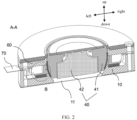
FIG. 2 is a cross-sectional view along line A-A inFIG. 1 ; -
FIG. 3 is an enlarged view of part B circled inFIG. 2 ; -
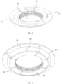
FIG. 4 is a schematic diagram of fitting of a transmission member and piezoelectric elements of a camera module according to an embodiment of this application, viewed from one perspective; -
FIG. 5 is a schematic diagram of fitting of a transmission member and piezoelectric elements of a camera module according to an embodiment of this application, viewed from another perspective; -
FIG. 6 is a local cross-sectional view along line C-C inFIG. 4 ; -
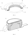
FIG. 7 is a schematic structural diagram of a lens module of a camera module according to an embodiment of this application; -
FIG. 8 is a schematic diagram of a lens module of a camera module rotating about an X-axis or Y-axis direction according to an embodiment of this application; and -
FIG. 9 is a schematic diagram of fitting of four piezoelectric elements of a camera module according to an embodiment of this application. - Reference signs are described as follows:
-
camera module 100; -
bracket 10;groove 11; -
drive member 20; firstpiezoelectric element 21; secondpiezoelectric element 22; thirdpiezoelectric element 23; fourthpiezoelectric element 24; -
transmission member 30;mounting channel 31;first segment 32;second segment 33; -
lens module 40; -
lens bracket 41;lens bracket body 411;annular groove 412;friction piece 413; -
lens 42; -
protrusion assembly 50;protrusion part 51; - fixing
bracket 60; andflexible circuit board 70. - The embodiments of this application are described in detail below. Examples of the embodiments are shown in the accompanying drawings, and reference signs that are the same or similar always indicate the same or similar components or components with the same or similar functions. The embodiments described below with reference to the drawings are illustrative and merely for explaining this application. They should not be construed as limitations on this application. Persons of ordinary skill in the art can still obtain other embodiments based on the embodiments of this application without creative efforts, and all these embodiments shall fall within the protection scope of this application.
- A feature modified by the term "first", "second", or the like in the specification and claims of this application can explicitly or implicitly include one or more such features. In the descriptions of this application, "a plurality of" means at least two unless otherwise stated. In addition, "and/or" in the specification and claims represents at least one of connected objects, and the character "/" generally indicates that the associated objects have an "or" relationship.
- In the descriptions of this application, it should be understood that the orientations or positional relationships indicated by the terms "center", "longitudinal", "transverse", "length", "width", "thickness", "upper", "lower", "front", "rear", "left", "right", "vertical", "horizontal", "top", "bottom", "inside", "outside", "clockwise", "counterclockwise", "axial", " radial", "circumferential", and the like are based on the orientations or positional relationships shown in the accompanying drawings. These terms are merely for the ease and brevity of description of the embodiments of this application rather than indicating or implying that the apparatuses or components mentioned in this application must have specific orientations or be constructed and manipulated according to specific orientations, and therefore shall not be construed as any limitations on this application.
- In the description of this application, it should be noted that unless otherwise specified and defined explicitly, the terms "mount", "connect", and "join" should be understood in their general senses. For example, they may refer to a fixed connection, a detachable connection, or an integral connection; a mechanical connection or an electrical connection; and a direct connection, an indirect connection via an intermediate medium, or an internal communication between two elements. Persons of ordinary skill in the art can understand specific meanings of these terms in this application as appropriate to specific situations.
- A
camera module 100 according to embodiments of this application is described with reference toFIGs. 1 to 9 . - As shown in
FIGs. 1 to 4 , thecamera module 100 according to embodiments of this application includes abracket 10, adrive member 20, atransmission member 30, and alens module 40. - Specifically, the
bracket 10 is provided with agroove 11, thedrive member 20 is disposed on a first side of thebracket 10, the transmission member is disposed on an inner wall of thegroove 11, and thetransmission member 30 is electrically connected to thedrive member 20. At least part of thelens module 40 is disposed in thegroove 11, thelens module 40 is movably connected to thetransmission member 30, and thetransmission member 30 is configured to drive thelens module 40 to move. - In other words, the
camera module 100 according to embodiments of the present invention mainly includes thebracket 10 with a support function, thedrive member 20 capable of generating a drive force, thetransmission member 30 connected to thedrive member 20 and capable of transmitting the drive force, and thelens module 40 connected to thetransmission member 30 and capable of moving under the action of the drive force. - Specifically, the
bracket 10 is provided with agroove 11, and at least part of thelens module 40 is provided in thegroove 11, and thelens module 40 can extend out of thegroove 11 to shoot the surrounding environment. Thedrive member 20 is disposed on the first side of thebracket 10 and can transmit the drive force through thetransmission member 30, thus driving thelens module 40 to move with respect to thebracket 10. Thetransmission member 30 is electrically connected to thedrive member 20, and thetransmission member 30 can drive thelens module 40 to move. - It should be noted that the
transmission member 30 and thebracket 10 are mounted in manners including but not limited to the following: - In one embodiment, the
transmission member 30 is arranged around an inner wall surface of thegroove 11, and a contact region between thetransmission member 30 and thelens module 40 can form an annular region to drive the outer side surface of thelens module 40. - In another embodiment, the
transmission member 30 is provided in a plurality of mounting positions on the inner wall surface of thegroove 11, where the plurality of mounting positions may be symmetrically or asymmetrically arranged with respect to thelens module 40. When the plurality of mounting positions are symmetrical with respect to thelens module 40, two or four mounting positions can be provided. For ease of description, it is defined that thebracket 10 extends along plane xy and thegroove 11 extends along direction z. - When two mounting positions are provided, one of them may be located in axis x and the other may be located in axis y, allowing the
lens module 40 to move around x and y. - When four mounting positions are provided, two of them may be located in axis x and the other two may be located in axis y. In addition, the four mounting positions may be arranged symmetrically with respect to the
lens module 40. It should be noted that symmetrically providing an even quantity of mounting positions helps to precisely control the swinging amplitude of thelens module 40 when thelens module 40 rotates around a specific direction. - In addition, the
transmission member 30 of thecamera module 100 according to embodiments of the present invention is not limited to the arrangement on the inner wall of thegroove 11 but may instead be arranged on the extension line of the inner wall surface of thegroove 11. For example, as shown inFIG. 2 , the lower part of thelens module 40 is located in thegroove 11, and thetransmission member 30 is disposed above thebracket 10 and on the extension line of the inner wall surface of thegroove 11 and can be connected to the middle part of thelens module 40 to drive thelens module 40 to move. - As such, according to the
camera module 100 of embodiments of this application, when thecamera module 100 shakes, thedrive member 20 can drive, through the cooperation with thetransmission member 30, thelens module 40 to move in the direction opposite to the shaking of thecamera module 100, thus counteracting the shaking caused by vibration, allowing thecamera module 100 to have an anti-shake function. - According to an embodiment of this application, the
transmission member 30 includes afirst segment 32 and asecond segment 33 that are connected sequentially, thefirst segment 32 being disposed on the first side of thebracket 10, and thedrive member 20 being disposed between thebracket 10 and thefirst segment 32. Thesecond segment 33 is disposed on the inner wall of thegroove 11, and an end of thesecond segment 33 back away from the first segment is movably connected to thelens module 40. It should be noted that thesecond segment 33 may be disposed on an inner wall of thegroove 11 or on the extension line of the inner wall of thegroove 11, which is not limited herein. - In this embodiment, the
transmission member 30 is designed as a structure where thefirst segment 32 and thesecond segment 33 fit with each other, which can not only ensure the contact area between thefirst segment 32 and thedrive member 20, but also ensure the effective contact between thesecond segment 33 and thelens module 40, thus improving the stability and precision of anti-shaking of thelens module 40. - Further, the
first segment 32 and thesecond segment 33 are integrally formed, which facilitates the processing and production. In addition, thesecond segment 33 is an annular structure. This can not only improve the balance of the support force for thelens module 40, but also expand the contact area between thetransmission member 30 and thelens module 40, thus facilitating the movement of thelens module 40 at multiple freedom degrees and multiple angles. - Optionally, arranging the
bracket 10 as an annular member co-axial with thetransmission member 30 can not only support thetransmission member 30, but also avoid thebracket 10 impeding the movement of thelens module 40. - For ease of description, it is defined below that the
transmission member 30 and thebracket 10 extend along the horizontal direction. - The
groove 11 and thedrive member 20 are disposed above thebracket 10, thefirst segment 32 in contact with thedrive member 20 is disposed above thedrive member 20, and thedrive member 20 can transmit the drive force to thelens module 40 through thefirst segment 32 and thesecond segment 33 and drive, through a friction force, thelens module 40 to move. It should be noted that thesecond segment 33 can also be in direct contact with thedrive member 20, which is not limited herein. - In some specific implementations of this application, as shown in
FIGs. 4 to 6 , an inner peripheral surface of thetransmission member 30 is provided with aprotrusion assembly 50 along a peripheral direction of the transmission member, and theprotrusion assembly 50 can improve the friction force between thetransmission member 30 and thelens module 40. Theprotrusion assembly 50 includes a plurality ofprotrusion parts 51, the plurality ofprotrusion parts 51 being spaced apart along the peripheral direction of thetransmission member 30. Each of theprotrusion parts 51 protrudes inward with respect to an inner surface of thetransmission member 30, and an inner surface of each of theprotrusion parts 51 abuts against thelens module 40. The drive member can transmit the drive force to theprotrusion parts 51. For example, when the drive force is a vibration force, the correspondingprotrusion parts 51 can also vibrate. In other words, theprotrusion parts 51 can not only expand the deformation degree of thetransmission member 30, but also partition the friction force between thetransmission member 30 and thelens module 40, thus improving the precision of controlling the movement angle and movement range of thelens module 40. - It should be noted that each of the
protrusion parts 51 abutting against thelens module 40 can further improve the friction force between thetransmission member 30 and thelens module 40, facilitating the movement of thelens module 40, and can also ensure the operation stability of thelens module 40 when thetransmission member 30 transmits the drive force to thelens module 40. - In other words, as shown in
FIG. 4 , in a case that thetransmission member 30 is an annular member, an annular hollow region of the annular member forms a mountingchannel 31. The inner wall surface of the annular member is provided with theprotrusion parts 51 that extend in the direction of the central axis of the mountingchannel 31 and protrude from the inner wall surface of the annular member. Theprotrusion part 51 is provided in plurality. The plurality ofprotrusion parts 51 can be spaced apart along the inner wall surface of the annular member, and the plurality ofprotrusion parts 51 can enclose an annular shape. When the high side of thetransmission member 30 extends in the up-and-down direction, the gap between twoadjacent protrusion parts 51 may be designed to extend in the up-and-down direction. This helps thetransmission member 30 to drive thelens module 40 to rotate about the Z-axis direction. - It should be noted that when the
transmission member 30 is located above thedrive member 20 and part of thedrive member 20 vibrates, theprotrusion part 51, corresponding to the vibrated part of the drive member, on thetransmission member 30, moves synchronously. - Further, at least two
protrusion assemblies 50 are provided, and the quantity of theprotrusion assemblies 50 may be odd or even and is not limited. The at least twoprotrusion assemblies 50 are spaced apart along the axial direction of thegroove 11. As shown inFIGs. 2 ,4 , and6 , twoprotrusion assemblies 50 are provided. When the high side of thetransmission member 30 extends in the up-and-down direction, the twoprotrusion assemblies 50 can be spaced apart in the up-and-down direction. A gap between the twoadjacent protrusion assemblies 50 can extend along a horizontal direction. This helps thetransmission member 30 to drive thelens module 40 to move along the X-axis and Y-axis directions. - Optionally, as shown in
FIGs. 4 to 6 , theprotrusion part 51 is in a shape of a long strip extending along the axial direction of thetransmission member 30, for example, a trapezium or rectangle. The plurality ofprotrusion parts 51 of twoadjacent protrusion assemblies 50 are in one-to-one correspondence in position in the axial direction of thetransmission member 30, such that the direction of the action force applied by thetransmission member 30 to thelens module 40 is controlled precisely using thedrive member 20, thus preventing the twoprotrusion assemblies 50 from interfering with each other. - In some specific implementations of this application, the
drive member 20 is a piezoelectric element. - The piezoelectric element according to embodiments of this application is described in detail below with reference to the accompanying drawings.
- As shown in
FIG. 2 , being above thebracket 10 is defined as being on the first side of thebracket 10. In other words, the piezoelectric element may be disposed above thebracket 10, and thetransmission member 30 may be disposed above the piezoelectric element. In a case that thetransmission member 30 is an annular member, the mountingchannel 31 can be formed in thetransmission member 30, at least part of thelens module 40 can be disposed in the mountingchannel 31, and the outer peripheral surface of thelens module 40 is connected to the inner peripheral surface of thetransmission member 30. Therefore, when energized, the piezoelectric element can generate a drive force through vibration and thetransmission member 30 can be connected to the piezoelectric element and transmit the drive force, allowing thelens module 40 to move under the drive force. Thebracket 10 may be a metal member able to improve the vibration amplitude. - It should be noted that the piezoelectric element includes a piezoelectric vibration material having a piezoelectric effect, and the piezoelectric vibration material can convert mechanical and electrical energies to each other. Piezoelectric vibration materials mainly include piezoelectric ceramics, piezoelectric fibers, and the like. It should be noted that the piezoelectric effect means that some crystals generate charges proportionally under the action of a mechanical stress or deform geometrically and proportionally under the action of an external electric field. Piezoelectric effects can be classified into direct piezoelectric effect and inverse piezoelectric effect. The inverse piezoelectric effect means that when an electric field is applied to a piezoelectric crystal in the absence of an external force, centers of positive and negative charges therein are displaced and in turn the material is mechanically deformed, where the magnitude of the deformation is proportional to the intensity of the electric field.
- In other words, when an operating voltage is input to the piezoelectric element of the
camera module 100 according to embodiments of this application, the piezoelectric element can deform, thereby generating vibration. This in turn drives at least part of thetransmission member 30 connected to the piezoelectric element to vibrate in the ultrasonic frequency range. It should be noted that, with the operating position of the piezoelectric element and the operating voltage input to the piezoelectric element controlled, different parts of the piezoelectric element can deform to different degrees, for example, generating an annular traveling wave. - In addition, as shown in
FIG. 4 , during assembly, the lower end of thelens module 40 is mounted in the mountingchannel 31, and the relative positional relationship between the upper end of thelens module 40 and the upper end of the mountingchannel 31 is not limited. After energized, the piezoelectric element can deform and vibrate. Because thetransmission member 30 is connected to both the piezoelectric element and thelens module 40, thetransmission member 30 can transmit the drive force generated by the piezoelectric element to thelens module 40, causing thelens module 40 to move. In addition, because the outer peripheral surface of thelens module 40 is connected to the inner peripheral surface of thetransmission member 30, thetransmission member 30 can support thelens module 40 and also limit its position, and a friction force is generated between thetransmission member 30 and thelens module 40 during vibration of thetransmission member 30, where the friction force can serve as a drive force to push thelens module 40 to move in the mountingchannel 31. - It should be noted that the
camera module 100 according to embodiments of this application is applicable to electronic devices including but not limited to cell phones. Thecamera module 100 according to embodiments of this application can also have an anti-shake effect during picture or video shooting. Optionally, thecamera module 100 according to embodiments of this application further includes a gyroscope and a processor. The gyroscope can first measure the shake direction and shake angle of thelens module 40. The processor can then receive the data sent by the gyroscope, calculate the operating voltage to be input to the piezoelectric element based on the shake angle, and select the operating position of the piezoelectric element according to the shake direction. After that, the processor inputs the operating voltage to the piezoelectric element, so that different parts of the piezoelectric element experience different degrees of deformation, thus causing different parts of thetransmission member 30 to deform and vibrate. The friction thus caused drives thelens module 40 to move in a preset angle, thus compensating the vibrating optical path of thelens module 40 for displacement or rotation, reducing the blur of shots. - According to this embodiment, the
transmission member 30 indirectly connects the piezoelectric element having the inverse piezoelectric effect to thelens module 40, with the operating voltage input to the piezoelectric element controlled, so that thetransmission member 30 vibrates, and thetransmission member 30 in vibration can drive, through friction, thelens module 40 to move. As compared with the prior art, thecamera module 100 according to embodiments of this application has an anti-shake effect and can drive thelens module 40 to provide displacement/rotation compensation. In addition, because theflexible circuit board 70 connected to the piezoelectric element in thecamera module 100 according to embodiments of this application is not pulled to a large extent, no S-shaped cable box that can receive theflexible circuit board 70 needs to be additionally disposed on a side of thelens module 40, thus saving the space, allowing for a high utilization of the internal space of an electronic device equipped with thecamera module 100 according to this embodiment of this application. In another aspect, because the piezoelectric element cooperates with thetransmission member 30, thetransmission member 30 can vibrate in the ultrasonic frequency range, thus expanding the movement range, for example, the rotation angle range, of thelens module 40. - Further, the piezoelectric element is sheet-shaped, with a first side abutting against the
bracket 10 and a second side abutting against thetransmission member 30. As shown inFIGs. 2 and3 , when the lower side of the piezoelectric element is defined as the first side and the upper side is defined as the second side, the piezoelectric element is sheet-shaped, with thebracket 10 provided below and thetransmission member 30 provided above. The upper end surface of the piezoelectric element can abut against thetransmission member 30 and the lower end surface of the piezoelectric element can abut against thebracket 10. The connection between the piezoelectric element and thetransmission member 30 may include tight compressing, bonding, welding, or the like. - Optionally, a plurality of piezoelectric elements are provided, for example, 4 as shown in
FIG. 5 . The plurality of piezoelectric elements are connected head to tail to form an annular shape corresponding to the shapes of thebracket 10 and thetransmission member 30. The corresponding direction of the friction force between thetransmission member 30 and thelens module 40 is controlled through the cooperation between at least two piezoelectric elements, thus improving the transmission efficiency of the drive force. It should be noted that the quantity of the piezoelectric elements includes but is not limited to 4, for example, being 6. The piezoelectric element may be provided in an odd or even quantity, which is not limited herein. - The movement of the
camera module 100 is described below with the quantity of piezoelectric elements being four with reference to the accompanying drawing. - As shown in
FIG. 9 , the four piezoelectric elements include a firstpiezoelectric element 21, a secondpiezoelectric element 22, a thirdpiezoelectric element 23, and a fourthpiezoelectric element 24. The four piezoelectric elements are all disposed on plane XY, thetransmission member 30 is located above the piezoelectric elements, and thelens module 40 and thetransmission member 30 are distributed along the Z-axis direction. The firstpiezoelectric element 21 and the secondpiezoelectric element 22 are arranged along the Y-axis direction and symmetrical about the axis X, the secondpiezoelectric element 22 and the thirdpiezoelectric element 23 are arranged along the X-axis direction and symmetrical about the axis Y, the thirdpiezoelectric element 23 and the fourthpiezoelectric element 24 are arranged along the Y-axis direction and symmetrical about the axis X, and the fourthpiezoelectric element 24 and the firstpiezoelectric element 21 are arranged along the X-axis direction and symmetrical about the axis Y - When two phases of sinusoidal excitation electrical signals with a phase difference of 90° are respectively applied to the first
piezoelectric element 21 and the thirdpiezoelectric element 23, the secondpiezoelectric element 22 and the fourthpiezoelectric element 24 do not operate, and thetransmission member 30 vibrates and drives, through friction, thelens module 40 to swing along the X-axis direction with the axis Z a symmetry axis. Exchanging the excitation signals applied to the firstpiezoelectric element 21 and the thirdpiezoelectric element 23 can change the movement direction of thelens module 40. - In the same way, when two phases of sinusoidal excitation electrical signals with a phase difference of 90° are respectively applied to the second
piezoelectric element 22 and the fourthpiezoelectric element 24, the firstpiezoelectric element 21 and the thirdpiezoelectric element 23 do not operate, and thelens module 40 can swing along the Y-axis direction with the axis Z a symmetry axis. Exchanging the excitation signals applied to the secondpiezoelectric element 22 and the fourthpiezoelectric element 24 can change the movement direction of thelens module 40. - When signals such as two phases of sinusoidal excitation electrical signals with a phase difference of 90° are respectively applied to the first
piezoelectric element 21 and secondpiezoelectric element 22, the secondpiezoelectric element 22 and thirdpiezoelectric element 23, the thirdpiezoelectric element 23 and fourthpiezoelectric element 24, or the fourthpiezoelectric element 24 and firstpiezoelectric element 21, thelens module 40 rotates about the Z-axis direction with the axis Z a symmetry axis. - Based on this, during picture or video shooting, the processor can calculate the operating voltage to be input to the piezoelectric element based on the shake angle of the camera module measured by the gyroscope and select, according to the data of shake direction, a piezoelectric element whose position is opposite to the shake direction as an operating piezoelectric element. That is, the four piezoelectric elements cooperate depending on the shake angle. Then, the processor inputs the operating voltage to the operating piezoelectric element, causing the operating piezoelectric element to deform and in turn causing the different parts of the
transmission member 30 to deform and vibrate. The friction drives thelens module 40 to rotate at any angle (about the X-axis direction, Y-axis direction, or Z-axis direction), thus implementing the displacement/rotation compensation for thelens module 40. - It can be seen that the cooperation between the plurality of piezoelectric elements can drive the
lens module 40 to rotate at large angles about the X-axis, Y-axis, and Z-axis directions, thus implementing the anti-shake function. - It should be noted that other types of excitation electrical signals may be input instead to control the movement direction and movement angle of the
lens module 40, which is not limited herein. - According to an embodiment of this application, as shown in
FIG. 2 andFIG. 8 , a side wall of thegroove 11 and an inner peripheral surface of thetransmission member 30 are both curved surfaces extending along an axial direction of thelens module 40. Thelens module 40 includes alens bracket 41 and alens 42. Thelens bracket 41 may be a columnar member, an outer peripheral surface of part of thelens bracket 41 is a curved friction surface, and the curved friction surface can be attached to the inner peripheral surfaces of thebracket 10 and thetransmission member 30. It should be noted that the curved friction surface can be connected to the curved surface of thetransmission member 30 alone or to both the curved surface of thebracket 10 and the curved surface of thetransmission member 30, which is not limited herein. Thelens 42 is provided in thelens bracket 41, thelens bracket 41 can support thelens 42 and limit its position, and thelens 42 and thelens bracket 41 can move synchronously. - It should be noted that, as compared with the rectangular lens bracket in the prior art, the outer peripheral surface of the
lens bracket 41 arranged as a curved friction surface can not only reduce the size of thelens bracket 41, but also help thelens bracket 41 to drive thelens 42 to move at multiple angles, for example, to move along the axis X, axis Y, and axis Z. This can effectively prevent thelens bracket 41 in motion from interfering with other components such as thebracket 10 and thetransmission member 30. Moreover, as the inner peripheral surfaces of thebracket 10 and thetransmission member 30 are arranged as curved surfaces and a side of theprotrusion part 51 facing towards thelens bracket 41 is also arranged as a curved surface, the attachment fitting between theprotrusion part 51 and thelens bracket 41 can be improved, thus improving the stability of thelens module 40 in motion. In addition, the overall size of thecamera module 100 can be also reduced, thus allowing for a high utilization of the internal space of an electronic device equipped with thecamera module 100. - In addition, as shown in
FIGs. 1 and2 , above thetransmission member 30, a fixingbracket 60 is also provided which is disposed on the first side of thebracket 10. The fixingbracket 60 is provided with a through hole, meaning the fixingbracket 60 can be formed as a hollow annular member. Thelens module 40 faces towards the through hole so as to find a view via the through hole. Optionally, thetransmission member 30 may be screwed to the fixingbracket 60. The inner wall surface of the fixingbracket 60 is formed as a curved surface, and the curved surfaces of the fixingbracket 60, thetransmission member 30, and thebracket 10 can smoothly transition. The shape of the entire curved surface formed by the three is roughly the same as the shape of the curved friction surface of thelens bracket 41, facilitating the rotation of thelens bracket 41. - Optionally, as shown in
FIG. 7 , thelens bracket 41 includes alens bracket body 411 and afriction piece 413. Thelens bracket body 411 is a columnar member, the outer peripheral surface of thelens bracket 41 is provided with anannular groove 412 extending along its own peripheral direction, and thefriction piece 413 is provided in theannular groove 412. Thefriction piece 413 is mounted in manners including but not limited to snapping, bonding, and the like. Further, the outer peripheral surface of the friction piece is a curved friction surface. It should be noted that, as shown inFIG. 2 , when twoprotrusion assemblies 50 are provided and spaced apart in the up-and-down direction, at least part of thefriction piece 413 in the up-and-down direction is located between theprotrusion assemblies 50. This can not only increase the friction performance, but also improve the movement stability of thecamera module 100. - In some specific implementations of this application, as shown in
FIG. 7 , thefriction piece 413 corresponds to theannular groove 412 in shape, which facilitates not only the mounting of thefriction piece 413 but also the curve transition between the edge of thefriction piece 413 and thelens bracket body 411. As shown inFIG. 7 , in the axial direction of thetransmission member 30, the outer peripheral surface of thefriction piece 413 is longer than the inner peripheral surface of thetransmission member 30. In other words, when thelens module 40 moves, at least one of two ends of thefriction piece 413 in the up-and-down direction can extend beyond the end of thetransmission member 30. This can not only increase the rotation angle of thelens module 40, but also prevent thelens module 40 from separating from thetransmission member 30, thus avoiding that thelens module 40 cannot be reset. - In summary, the
camera module 100 according to the embodiments of this application transmits, through the cooperation between thedrive member 20 and thetransmission member 30, the drive force to thelens module 40, thus driving thelens module 40 to move. When the piezoelectric element having an inverse piezoelectric effect is used as thedrive member 20, the piezoelectric element can make thetransmission member 30 vibrate in the ultrasonic frequency range and make, through friction, the vibratingtransmission member 30 drive thelens module 40 to move. Thecamera module 100 according to the embodiments of this application not only has the advantages of high power, high efficiency, and good movement stability of thelens module 40, but also can implement the anti-shake effect when thelens module 40 rotates at a large angle about the X-axis, Y-axis, and Z-axis directions, thus improving the quality of shots. In addition, when applied to electronic devices, thecamera module 100 according to the embodiments of this application also has the advantage of occupying a small space, thus improving the internal space of the electronic device. - The electronic device according to the embodiments of this application can be any electronic devices suitable for including the
camera module 100, such as cell phones, laptops, tablet computers, or wearable devices. - In the description of this specification, descriptions referring to the terms "an embodiment", "some embodiments", "exemplary embodiments", "an example", "a specific example", or "some examples" mean the specific features, structures, materials or characteristics described with to the embodiment or example are included in at least one embodiment or example of this application. In this specification, illustrative expressions of these terms do not necessarily refer to the same embodiment or example. Moreover, the specific features, structures, materials, or characteristics described may be combined in any suitable manners in any one or more embodiments or examples.
- Although some embodiments of this application have been illustrated and described, those of ordinary skill in the art can understand that various changes, modifications, substitutions, and variations of these embodiments may be made without departing from the principle and purpose of this application, and the scope of this application is defined by the claims and their equivalents.
Claims (10)
- A camera module, comprising:a bracket, wherein the bracket is provided with a groove;a drive member, wherein the drive member is disposed on a first side of the bracket;a transmission member, wherein the transmission member is disposed on an inner wall of the groove, and the transmission member is electrically connected to the drive member; anda lens module, wherein at least part of the lens module is disposed in the groove, the lens module is movably connected to the transmission member, and the transmission member is configured to drive the lens module to move.
- The camera module according to claim 1, wherein the transmission member comprises a first segment and a second segment that are connected sequentially, whereinthe first segment is disposed on the first side of the bracket, and the drive member is disposed between the bracket and the first segment; andthe second segment is disposed on the inner wall of the groove, and an end of the second segment back away from the first segment is movably connected to the lens module.
- The camera module according to claim 2, wherein the first segment and the second segment are integrally formed, and the second segment is an annular structure.
- The camera module according to claim 1, wherein an inner peripheral surface of the transmission member is provided with a protrusion assembly along a peripheral direction of the transmission member, the protrusion assembly comprising a plurality of protrusion parts, wherein the plurality of protrusion parts are spaced apart along the peripheral direction of the transmission member, each of the protrusion parts protrudes inward with respect to an inner surface of the transmission member, and an inner surface of each of the protrusion parts abuts against the lens module.
- The camera module according to claim 4, wherein the protrusion assembly is provided in a quantity of at least two, and the at least two protrusion assemblies are spaced apart along an axial direction of the groove.
- The camera module according to claim 4 or 5, wherein the protrusion part is in a shape of a long strip extending along the axial direction of the transmission member, and the plurality of protrusion parts of adj acent two of the protrusion assemblies are in one-to-one correspondence in position in the axial direction of the transmission member.
- The camera module according to claim 1, wherein the drive member is a piezoelectric element.
- The camera module according to claim 7, wherein the piezoelectric element is provided in plurality, and the plurality of piezoelectric elements are connected head to tail to form an annular shape corresponding to a shape of the transmission member.
- The camera module according to claim 1, wherein a side wall of the groove and an inner peripheral surface of the transmission member are both curved surfaces extending along an axial direction of the lens module, and the lens module comprises:a lens bracket, wherein an outer peripheral surface of part of the lens bracket is a curved friction surface, the curved friction surface being attached to the inner peripheral surface of the transmission member; anda lens, wherein the lens is disposed in the lens bracket.
- The camera module according to claim 1, further comprising:
a fixing bracket, wherein the fixing bracket is disposed on the first side of the bracket, the fixing bracket is provided with a through hole, and the lens module faces toward the through hole.
Applications Claiming Priority (2)
| Application Number | Priority Date | Filing Date | Title |
|---|---|---|---|
| CN202011425602.3A CN112492175B (en) | 2020-12-08 | 2020-12-08 | Camera shooting module |
| PCT/CN2021/135631 WO2022121823A1 (en) | 2020-12-08 | 2021-12-06 | Camera module |
Publications (2)
| Publication Number | Publication Date |
|---|---|
| EP4262186A1 true EP4262186A1 (en) | 2023-10-18 |
| EP4262186A4 EP4262186A4 (en) | 2024-06-12 |
Family
ID=74940568
Family Applications (1)
| Application Number | Title | Priority Date | Filing Date |
|---|---|---|---|
| EP21902529.3A Pending EP4262186A4 (en) | 2020-12-08 | 2021-12-06 | Camera module |
Country Status (5)
| Country | Link |
|---|---|
| US (1) | US12578589B2 (en) |
| EP (1) | EP4262186A4 (en) |
| JP (1) | JP7576174B2 (en) |
| CN (1) | CN112492175B (en) |
| WO (1) | WO2022121823A1 (en) |
Families Citing this family (7)
| Publication number | Priority date | Publication date | Assignee | Title |
|---|---|---|---|---|
| CN112492175B (en) * | 2020-12-08 | 2022-06-10 | 维沃移动通信有限公司 | Camera shooting module |
| WO2022228112A1 (en) * | 2021-04-26 | 2022-11-03 | 宁波舜宇光电信息有限公司 | Camera module |
| CN115334212B (en) * | 2021-04-26 | 2025-08-08 | 宁波舜宇光电信息有限公司 | Camera module |
| CN115421344B (en) * | 2021-05-12 | 2026-03-06 | 宁波舜宇光电信息有限公司 | camera module |
| CN113315892B (en) * | 2021-05-14 | 2022-09-30 | 杭州海康威视数字技术股份有限公司 | Video camera |
| CN113448053B (en) * | 2021-07-30 | 2023-06-20 | 辽宁中蓝光电科技有限公司 | A piezoelectric three-axis camera driving device and driving method |
| CN114650355B (en) * | 2022-03-16 | 2024-06-11 | Oppo广东移动通信有限公司 | Mobile terminal and camera module thereof |
Family Cites Families (28)
| Publication number | Priority date | Publication date | Assignee | Title |
|---|---|---|---|---|
| JPH07115782A (en) * | 1993-10-13 | 1995-05-02 | Canon Inc | Vibration wave drive |
| JPH07234447A (en) | 1993-12-28 | 1995-09-05 | Canon Inc | Shooting unit and camera |
| JPH096435A (en) * | 1995-06-15 | 1997-01-10 | Omron Corp | Directional angle controller |
| JPH1094275A (en) * | 1996-09-11 | 1998-04-10 | Toshiba Corp | Multi-directional rotation drive type ultrasonic motor device |
| US6546202B1 (en) * | 2000-07-06 | 2003-04-08 | Fuji Photo Optical Co., Ltd. | Lens driving apparatus |
| JP2005311758A (en) * | 2004-04-22 | 2005-11-04 | Matsushita Electric Ind Co Ltd | Camera module and electronic device with camera |
| CN101206297B (en) * | 2006-12-20 | 2011-09-28 | 财团法人工业技术研究院 | Piezo Driven Optical Lens |
| CN101419318A (en) * | 2007-10-25 | 2009-04-29 | 鸿富锦精密工业(深圳)有限公司 | Camera module |
| WO2010059217A2 (en) | 2008-11-21 | 2010-05-27 | Ceradigm Corp. | Miniature piezoelectric motors for ultra high-precision stepping |
| JP5402448B2 (en) | 2009-09-16 | 2014-01-29 | 株式会社Jvcケンウッド | Dome camera |
| JP2012063423A (en) * | 2010-09-14 | 2012-03-29 | Nikon Corp | Lens barrel and imaging device |
| TWI528066B (en) * | 2011-11-21 | 2016-04-01 | 鴻海精密工業股份有限公司 | Actuator and camera module using same |
| CN103135317A (en) * | 2011-11-22 | 2013-06-05 | 鸿富锦精密工业(深圳)有限公司 | Actuator and camera module comprising same |
| JP6080033B2 (en) | 2012-04-19 | 2017-02-15 | パナソニックIpマネジメント株式会社 | Surveillance camera device |
| CN103095174A (en) | 2013-01-25 | 2013-05-08 | 东南大学 | Hollow annular traveling wave ultrasonic motor |
| CN204129405U (en) * | 2014-10-17 | 2015-01-28 | 联想(北京)有限公司 | Anti-shake apparatus and electronic equipment |
| JP6602041B2 (en) * | 2015-04-24 | 2019-11-06 | キヤノン株式会社 | Vibrating body, vibration type driving device, image forming apparatus, robot, and pan head device |
| KR102421717B1 (en) * | 2015-11-24 | 2022-07-18 | 삼성전자주식회사 | Photographing apparatus module, user terminal comprising the photographing apparatus |
| DE102017000889A1 (en) * | 2017-01-27 | 2018-08-02 | Christian Overmann | Modular optical recording system |
| WO2019130623A1 (en) * | 2017-12-27 | 2019-07-04 | 株式会社村田製作所 | Vibratory device and optical detection device |
| CN209167632U (en) * | 2018-11-27 | 2019-07-26 | 瑞声光学科技(常州)有限公司 | A kind of lens module |
| CN109922238B (en) * | 2019-02-27 | 2020-09-04 | Oppo广东移动通信有限公司 | Drive assembly and electronic equipment |
| CN114222037B (en) * | 2019-05-10 | 2024-04-02 | 荣耀终端有限公司 | Camera module and electronic equipment |
| CN111399163B (en) * | 2020-03-17 | 2024-05-21 | 睿恩光电有限责任公司 | Lens driving device with optical anti-shake function, camera device and electronic equipment |
| CN211791725U (en) * | 2020-04-30 | 2020-10-27 | 南昌欧菲光电技术有限公司 | Camera shooting assembly and electronic equipment with same |
| CN111580240B (en) * | 2020-06-15 | 2025-04-04 | 精拓丽音科技(北京)有限公司 | A zoom lens module and electronic equipment using the same |
| CN111679395B (en) * | 2020-06-23 | 2025-05-09 | 南昌欧菲光电技术有限公司 | Camera module and mobile terminal having the same |
| CN112492175B (en) * | 2020-12-08 | 2022-06-10 | 维沃移动通信有限公司 | Camera shooting module |
-
2020
- 2020-12-08 CN CN202011425602.3A patent/CN112492175B/en active Active
-
2021
- 2021-12-06 EP EP21902529.3A patent/EP4262186A4/en active Pending
- 2021-12-06 WO PCT/CN2021/135631 patent/WO2022121823A1/en not_active Ceased
- 2021-12-06 JP JP2023532328A patent/JP7576174B2/en active Active
-
2023
- 2023-06-06 US US18/329,695 patent/US12578589B2/en active Active
Also Published As
| Publication number | Publication date |
|---|---|
| KR20230117414A (en) | 2023-08-08 |
| EP4262186A4 (en) | 2024-06-12 |
| WO2022121823A1 (en) | 2022-06-16 |
| CN112492175B (en) | 2022-06-10 |
| US12578589B2 (en) | 2026-03-17 |
| JP7576174B2 (en) | 2024-10-30 |
| US20230314831A1 (en) | 2023-10-05 |
| CN112492175A (en) | 2021-03-12 |
| JP2023551478A (en) | 2023-12-08 |
Similar Documents
| Publication | Publication Date | Title |
|---|---|---|
| US12578589B2 (en) | Camera module | |
| CN111698352B (en) | Camera modules and electronic equipment | |
| EP4195700B1 (en) | Display apparatus | |
| EP3407623A1 (en) | Flat panel speaker, and display device | |
| EP3920554B1 (en) | Screen sound-generating device | |
| US20170257706A1 (en) | Sound generating unit and electronic device | |
| CN209417492U (en) | A high-performance and reliable miniature anti-shake head | |
| CN113411470B (en) | Camera module and electronic equipment | |
| JP7281583B1 (en) | lens driver | |
| JP7616753B2 (en) | Camera module and electronic device | |
| US12401873B2 (en) | Camera module and electronic device | |
| CN114390203A (en) | Anti-shake module | |
| KR20220055488A (en) | Camera module and mobile terminal | |
| WO2022041389A1 (en) | Optical image stabilization apparatus, camera and portable electronic device | |
| WO2024001378A1 (en) | Piezoelectric motor, and camera module using same | |
| WO2023124783A1 (en) | Photographing assembly and electronic device | |
| KR102967307B1 (en) | Camera module | |
| WO2023066101A1 (en) | Camera module and electronic device | |
| US20240007022A1 (en) | Piezoelectric motor, camera module, and electronic device | |
| CN112731729B (en) | Anti-shake cradle head | |
| WO2024087956A1 (en) | Driving unit, piezoelectric motor, camera module, and electronic device | |
| CN110275366B (en) | Lens driving device | |
| JP4834409B2 (en) | Dust remover | |
| TWI748298B (en) | Display module and electronic device using same | |
| KR20240062897A (en) | Lens driving apparatus and camera module including the same |
Legal Events
| Date | Code | Title | Description |
|---|---|---|---|
| STAA | Information on the status of an ep patent application or granted ep patent |
Free format text: STATUS: THE INTERNATIONAL PUBLICATION HAS BEEN MADE |
|
| PUAI | Public reference made under article 153(3) epc to a published international application that has entered the european phase |
Free format text: ORIGINAL CODE: 0009012 |
|
| STAA | Information on the status of an ep patent application or granted ep patent |
Free format text: STATUS: REQUEST FOR EXAMINATION WAS MADE |
|
| 17P | Request for examination filed |
Effective date: 20230628 |
|
| AK | Designated contracting states |
Kind code of ref document: A1 Designated state(s): AL AT BE BG CH CY CZ DE DK EE ES FI FR GB GR HR HU IE IS IT LI LT LU LV MC MK MT NL NO PL PT RO RS SE SI SK SM TR |
|
| DAV | Request for validation of the european patent (deleted) | ||
| DAX | Request for extension of the european patent (deleted) | ||
| REG | Reference to a national code |
Ref country code: DE Ref legal event code: R079 Free format text: PREVIOUS MAIN CLASS: H04N0005232000 Ipc: G02B0027640000 |
|
| A4 | Supplementary search report drawn up and despatched |
Effective date: 20240510 |
|
| RIC1 | Information provided on ipc code assigned before grant |
Ipc: H04N 23/68 20230101ALI20240503BHEP Ipc: G02B 27/64 20060101AFI20240503BHEP |
|
| STAA | Information on the status of an ep patent application or granted ep patent |
Free format text: STATUS: EXAMINATION IS IN PROGRESS |
|
| 17Q | First examination report despatched |
Effective date: 20250923 |