EP4262129B1 - Datenübertragungen in steuerregionen - Google Patents
Datenübertragungen in steuerregionen Download PDFInfo
- Publication number
- EP4262129B1 EP4262129B1 EP23177443.1A EP23177443A EP4262129B1 EP 4262129 B1 EP4262129 B1 EP 4262129B1 EP 23177443 A EP23177443 A EP 23177443A EP 4262129 B1 EP4262129 B1 EP 4262129B1
- Authority
- EP
- European Patent Office
- Prior art keywords
- data transmission
- region
- control
- resources
- time
- Prior art date
- Legal status (The legal status is an assumption and is not a legal conclusion. Google has not performed a legal analysis and makes no representation as to the accuracy of the status listed.)
- Active
Links
Images


Classifications
-
- H—ELECTRICITY
- H04—ELECTRIC COMMUNICATION TECHNIQUE
- H04L—TRANSMISSION OF DIGITAL INFORMATION, e.g. TELEGRAPHIC COMMUNICATION
- H04L5/00—Arrangements affording multiple use of the transmission path
- H04L5/0001—Arrangements for dividing the transmission path
- H04L5/0003—Two-dimensional division
- H04L5/0005—Time-frequency
- H04L5/0007—Time-frequency the frequencies being orthogonal, e.g. OFDM(A) or DMT
-
- H—ELECTRICITY
- H04—ELECTRIC COMMUNICATION TECHNIQUE
- H04L—TRANSMISSION OF DIGITAL INFORMATION, e.g. TELEGRAPHIC COMMUNICATION
- H04L5/00—Arrangements affording multiple use of the transmission path
- H04L5/003—Arrangements for allocating sub-channels of the transmission path
- H04L5/0044—Allocation of payload; Allocation of data channels, e.g. PDSCH or PUSCH
-
- H—ELECTRICITY
- H04—ELECTRIC COMMUNICATION TECHNIQUE
- H04L—TRANSMISSION OF DIGITAL INFORMATION, e.g. TELEGRAPHIC COMMUNICATION
- H04L5/00—Arrangements affording multiple use of the transmission path
- H04L5/003—Arrangements for allocating sub-channels of the transmission path
- H04L5/0053—Allocation of signalling, i.e. of overhead other than pilot signals
-
- H—ELECTRICITY
- H04—ELECTRIC COMMUNICATION TECHNIQUE
- H04L—TRANSMISSION OF DIGITAL INFORMATION, e.g. TELEGRAPHIC COMMUNICATION
- H04L5/00—Arrangements affording multiple use of the transmission path
- H04L5/0091—Signalling for the administration of the divided path, e.g. signalling of configuration information
-
- H—ELECTRICITY
- H04—ELECTRIC COMMUNICATION TECHNIQUE
- H04W—WIRELESS COMMUNICATION NETWORKS
- H04W72/00—Local resource management
- H04W72/04—Wireless resource allocation
- H04W72/044—Wireless resource allocation based on the type of the allocated resource
- H04W72/0446—Resources in time domain, e.g. slots or frames
-
- H—ELECTRICITY
- H04—ELECTRIC COMMUNICATION TECHNIQUE
- H04W—WIRELESS COMMUNICATION NETWORKS
- H04W72/00—Local resource management
- H04W72/04—Wireless resource allocation
- H04W72/044—Wireless resource allocation based on the type of the allocated resource
- H04W72/0453—Resources in frequency domain, e.g. a carrier in FDMA
-
- H—ELECTRICITY
- H04—ELECTRIC COMMUNICATION TECHNIQUE
- H04W—WIRELESS COMMUNICATION NETWORKS
- H04W72/00—Local resource management
- H04W72/20—Control channels or signalling for resource management
- H04W72/23—Control channels or signalling for resource management in the downlink direction of a wireless link, i.e. towards a terminal
- H04W72/232—Control channels or signalling for resource management in the downlink direction of a wireless link, i.e. towards a terminal the control data signalling from the physical layer, e.g. DCI signalling
Definitions
- Particular embodiments are directed to wireless communications and, more particularly, to transmission of user data in a control region.
- PDCCHs physical downlink control channels
- DCI downlink control information
- the PDCCHs are in general transmitted at the beginning of a slot and relate to data in the same or a later slot (for mini-slots PDCCH can also be transmitted within a regular slot).
- Different formats (sizes) of the PDCCHs are possible to handle different DCI payload sizes and different aggregation levels (i.e., different code rate for a given payload size).
- a user equipment is configured (implicitly and/or explicitly) to blindly monitor (or search) for a number of PDCCH candidates of different aggregation levels and DCI payload sizes.
- Upon detecting a valid DCI message i.e., the decoding of a candidate is successful, and the DCI contains an identity (ID) the UE is to monitor) the UE follows the DCI (e.g., receives the corresponding downlink data or transmits in the uplink).
- the blind decoding process comes at a cost in complexity in the UE but is required to provide flexible scheduling and handling of different DCI payload sizes.
- NR includes specifications on how to configure control resource regions where the UE can monitor for PDCCH transmissions and how a UE can be configured with multiple control resource regions. Some of these control regions may be used for sending common control messages that are intended for multiple UEs and some may be intended for UE-specific control messages. A control region may serve both common and UE-specific control messages.
- LTE long term evolution
- the carrier bandwidths may be larger. Thus, there are benefits if the control region does not span the entire bandwidth of the carrier. Therefore, control regions may be limited in time and in frequency.
- Control regions are generally dimensioned to ensure that multiple UEs can be signaled within the region. To do this, statistical multiplexing may be used where the number of UEs that are assigned to a control region to search for control messages is much greater than the resource available in the control region. Therefore, the search spaces for different UEs are randomized so that statistical multiplexing can be used to minimize the blocking probability when any particular UE needs to be scheduled. Therefore, control regions may be dimensioned to be able to signal PDCCHs for multiple UEs simultaneously and the number of UEs that are assigned to monitor the control region is expected to be greater than the number of UEs that can simultaneously be signaled.
- a UE may be configured with one or more control regions, which the UE monitors for the potential reception of one or more PDCCHs.
- the control regions for one UE or different UEs can, in principle, partly or fully overlap.
- Document US 2016/308648 A1 may be construed to disclose a method, apparatus and system for indicating downlink resources of a coordinated multi-point network in an LTE system.
- the method includes: determining a control station/cell and a service station/cell of a User Equipment (UE); and indicating through signaling that a Physical Downlink Shared Channel (PDSCH) of the UE occupies radio resources of the service station/cell in a control region, whereby a start position of the PDSCH allocated for the UE by the service station/cell is the first symbol of a subframe, and when a resource mapping in the control region is performed, the PDSCH does not occupy Resource Elements (REs) occupied by a Cell Reference Signal (CRS), a Physical Control Format Indicator Channel (PCFICH), a Physical Hybrid-ARQ Indicator Channel (PHICH) of a station/cell where the PDSCH is located, and a Physical Downlink Control Channel PDCCH of the UE.
- Document US 2013/094458 A1 may be construed to disclose a method for operating a communications controller including allocating a number of resource blocks to an enhanced physical downlink shared channel (ePDSCH), and identifying a starting point for the resource blocks of the ePDSCH, the starting point located within a control region of a subframe.
- the method also includes signaling to a user equipment (UE) the starting point of the resource blocks and the number of resource blocks allocated to the ePDSCH.
- UE user equipment
- Document US 2012/320846 A1 may be construed to disclose methods and apparatus for a User Equipment (UE) to receive over a first set of resources a Physical Downlink Control CHannel (PDCCH) of a first type including Control Channel Elements (CCEs) of a first type, to receive over a second set of resources a PDCCH of a second type including CCEs of a second type, and to determine a resource for transmitting an acknowledgement signal in response to detecting the PDCCH of the first type or in response to detecting the PDCCH of the second type.
- UE User Equipment
- PDCCH Physical Downlink Control CHannel
- CCEs Control Channel Elements
- NR Third Generation Partnership Project
- 3GPP Third Generation Partnership Project
- 5G fifth generation
- NR includes specifications on how to configure control resource regions where a user equipment (UE) can monitor for physical downlink control channel (PDCCH) transmissions and how a UE can be configured with multiple control resource regions. Some of these control regions may be used for sending common control messages that are intended for multiple UEs and some may be intended for UE-specific control messages. A control region may serve both common and UE-specific control messages.
- LTE long term evolution
- control regions may be limited in time and in frequency.
- Control regions are generally dimensioned to ensure that multiple UEs can be signaled within the region.
- the search spaces for different UEs are randomized so that statistical multiplexing can be used to minimize the blocking probability when any particular UE needs to be scheduled.
- a CORESET is a control resource set that is configured to the UE.
- a CORESET is a set of REs that spans a set of physical resource blocks (PRBs) in frequency and orthogonal frequency division multiplexing (OFDM) symbols in time.
- PRBs physical resource blocks
- OFDM orthogonal frequency division multiplexing
- a UE may be configured one or more CORESETs which the UE should monitor for the potential reception of one or more PDCCHs.
- CORESETs for one UE or different UEs can in principle be (partly) overlapping. For simplicity, in the figures below it is assumed that the CORESETs are not partly overlapping.
- Particular embodiments obviate the problems described above and include signaling to the UE on three aspects that informs the UE how control region resource should be reused. These are the starting position of the data transmission, the physical resource blocks in frequency that are used for data transmission and options on how to reuse unused resources in the one or more control regions configured to the UE including the option of not reusing any unused resources in the control regions.
- Particular embodiments optimize the overhead of such signaling by using a field with as few bits as possible and encoding the values for the field with specific options for reuse of control resources as defined by the above three aspects.
- Particular embodiments enable data transmissions that must be sent urgently with very low latency to occur purely in one or more of the control regions defined for the UE
- Particular embodiments provide a flexible way of maximizing data throughput by reusing unused resources in configured control regions. Particular embodiments provide a robust method for enabling low latency transmissions to be multiplexed with data transmissions.
- LTE Long Term Evolution
- FIGURES 1-11 of the drawings like numerals being used for like and corresponding parts of the various drawings
- LTE is used throughout this disclosure as an example cellular system, but the ideas presented herein may apply to other wireless communication systems as well.
- wireless devices 110 that are within coverage of network node 120 (e.g., within cell 115 served by network node 120) communicate with network node 120 by transmitting and receiving wireless signals 130.
- wireless devices 110 and network node 120 may communicate wireless signals 130 containing voice traffic, data traffic, and/or control signals.
- a network node 120 communicating voice traffic, data traffic, and/or control signals to wireless device 110 may be referred to as a serving network node 120 for the wireless device 110, Communication between wireless device 110 and network node 120 may be referred to as cellular communication.
- Wireless signals 130 may include both downlink transmissions (from network node 120 to wireless devices 110) and uplink transmissions (from wireless devices 110 to network node 120).
- Each network node 120 may have a single transmitter 140 or multiple transmitters 140 for transmitting signals 130 to wireless devices 110, In some embodiments, network node 120 may comprise a multi-input multi-output (MIMO) system. Similarly, each wireless device 110 may have a single receiver or multiple receivers for receiving signals 130 from network nodes 120 or other wireless devices 110.
- MIMO multi-input multi-output
- Wireless signals 130 may include particular time and frequency resources allocated as control resources.
- the resources may be referred to as a control region.
- One example of time and frequency resources allocated as control resources is a CORESET.
- Other embodiments may include other types of control regions.
- network node 120 may determine one or more control resource regions (e.g., control resource set (CORESET)) for a carrier. Each control resource region comprises a set of time and frequency resources (described by physical resource blocks, OFDM symbols, frequency range, etc.). Network node 120 may determine a control channel region (e.g., PDCCH) in a control resource region. The control channel region may comprise a subset of the time frequency resources of the first control resource region. Network node 120 may determine a data transmission region in a control resource region. Network node 120 may signal the determined data transmission region to wireless device 110.
- control resource region e.g., control resource set (CORESET)
- Each control resource region comprises a set of time and frequency resources (described by physical resource blocks, OFDM symbols, frequency range, etc.).
- Network node 120 may determine a control channel region (e.g., PDCCH) in a control resource region. The control channel region may comprise a subset of the time frequency resources of the first control resource region.
- Network node 120 may signal to wireless device 110 on three aspects that inform wireless device 110 how a control region resource may be reused. These are the starting position of the data transmission, the physical resource blocks in frequency that are used for data transmission, and options on how to reuse unused resources in the one or more control regions configured to wireless device 110, including the option of not reusing any unused resources in the control regions.
- the data transmission region comprises a subset of the resources in the at least one control resource region.
- the data transmission region may exclude resources for the control channel region.
- network node 120 may signal the determined data transmission region to wireless device 110 using a bitmap.
- the bitmap may indicate time and frequency resources used for the data transmission region, or time and frequency resources excluded from the data transmission region.
- Other embodiments may use an identifier of at least one control resource region to include or exclude with respect to the data transmission region.
- wireless device 110 receives a control channel (e.g., PDCCH) that includes control information that indicates a set of time and frequency resources allocated for the wireless device to receive a data transmission.
- a control channel e.g., PDCCH
- Wireless device 110 may determine that the set of time and frequency resources allocated for data transmission overlaps with a control resource region (e.g., CORESET).
- Wireless device 110 may transmit or receive a data transmission in the set of time and frequency resources allocated for data transmission.
- each network node 120 may use any suitable radio access technology, such as long term evolution (LTE), LTE-Advanced, UMTS, HSPA, GSM, cdma2000, NR, WiMax, WiFi, and/or other suitable radio access technology.
- Wireless network 100 may include any suitable combination of one or more, radio access technologies, For purposes of example, various embodiments may be described within the context of certain radio access technologies. However, the scope of the disclosure is not limited to the examples and other embodiments could use different radio access technologies.
- a wireless network may include one or more wireless devices and one or more different types of radio network nodes capable of communicating with the wireless devices.
- the network may also include any additional elements suitable to support communication between wireless devices or between a wireless device and another communication device (such as a landline telephone).
- a wireless device may include any suitable combination of hardware and/or software.
- a wireless device such as wireless device 110
- a network node may include any suitable combination of hardware and/or software.
- a network node, such as network node 120 may include the components described with respect to FIGURE 11 below.
- Various embodiments include signaling information. Portions of some signaling may be known, such as that a PDCCH message may indicate the resources in frequency, i.e., the physical resource blocks (PRBs) that are allocated for data transmission to the UE, and that a PDCCH message may indicate a starting symbol for data transmissions.
- PRBs physical resource blocks
- the embodiments described herein also include methods to reuse unused resources in the control resource regions (e.g., CORESETs) configured to the UE for the purpose of data reception and transmission.
- CORESETs control resource regions
- a first group of embodiments include interpretation of starting symbol for data transmissions.
- the starting symbol for data transmissions is applicable only to PRBs that are fully outside any control resource regions (e.g., CORESETs) configured to the UE. That is, unless otherwise indicated by methods outlined in the embodiments below, the UE assumes that the data transmission (PDSCH) is mapped to the REs in time and frequency indicated by the allocated PRBs and the starting symbol, but excluding any REs that are part of control resource regions (e.g., CORESETs) configured to the UE.
- PDSCH data transmission
- a second group of embodiments include control region reuse to avoid resources on which a UE receives a control channel (e.g., PDCCH).
- the resources in the control resource region that are reused for data transmission do not include the resources on which a PDCCH has been received.
- this group of embodiments is similar to the first group of embodiments in the sense that the UE follows the resource allocation given by the starting symbol and RBs in the frequency domain, but instead of excluding all REs in the entire control resource region (e.g., CORESET) from the allocation, only the REs upon which the UE detected a control channel (e.g., PDCCH) are excluded.
- a third group of embodiments include control region reuse within a time and frequency region indicated by scheduled PRBs and start symbol for data.
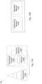
- the resources in the control region are only reused within the time and frequency region indicated by the scheduled PRBs and start symbol for data. This is illustrated in FIGURE 2 where a UE receives a PDCCH in a CORESET, but the UE is scheduled to transmit PRBs only spanning a part of the CORESET bandwidth.
- FIGURE 2 illustrates an example of the reuse of resources in the CORESET only within the time and frequency region indicated by the scheduled PRBs and start symbol for data, according to a particular embodiment.
- the illustrated example includes a transmission time interval comprising a plurality of OFDM symbols 42.
- the transmission time interval includes control resource regions 10 (e.g., 10a and 10b), a control channel 12, and data transmission region 14.
- the UE receiving control channel 12 (e.g., PDCCH 12) for scheduled data transmission region 14a is configured with two control resource regions 10a (e.g., CORESETs 10a).
- Control resource region 10a comprises two groups of PRBs in the first two OFDM symbols.
- Control resource region 10B comprises one group of PRBs in the first two OFDM symbols.
- a network node such as network node 120 described above, may use control resource regions 10 for sending control channels to a UE, such as wireless device 110 described above.
- network node 120 may send control channel 12 to wireless device 110 to schedule a downlink transmission (e.g., PDCCH with DCI).
- the scheduling information for the downlink transmission indicates to the UE which time and frequency resources will be used for the downlink transmission.
- the time and frequency resources are represented by data transmission region 14.
- data transmission region 14 starts at the first OFDM symbol and continues in each OFDM symbol of the transmission time interval.
- the frequency range of the resources allocated for data transmission is the same inside control resource region 10a as outside control resource region 10a.
- the portion of data transmission region 14 inside control resource region 10a does not overlap with control channel region 12.
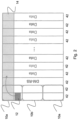
- FIGURE 3 illustrates another example of the reuse of resources in the CORESET only within the time and frequency region indicated by the scheduled PRBs and start symbol for data, according to a particular embodiment.
- the illustrated example includes a transmission time interval comprising a plurality of OFDM symbols 42, control resource regions 10, control channels 12 and 16, and data transmission regions 14 and 18.
- a first UE receiving control channel 12 (e.g., PDCCH 12) for scheduled data transmission region 14 is configured with two control resource regions 10a (e.g., CORESETs 10a) in the first two OFDM symbols.
- a second UE receiving control channel 16 (e.g., PDCCH 16) for scheduled data transmission region 18 is also configured with two control resource regions 10a (e.g., CORESETs 10a) in the first two OFDM symbols.
- network node 120 may send control channel 12 (e.g., PDCCH 12) that includes downlink control information to a first wireless device 110 to schedule a downlink transmission in the time and frequency resources represented by data transmission region 14.
- Network node 120 may send control channel 16 (e.g., PDCCH 16) that includes downlink control information to a second wireless device 110 to schedule a downlink transmission in the time and frequency resources represented by data transmission region 18.
- data transmission region 14 starts at the first OFDM symbol and continues in each OFDM symbol of the transmission time interval.
- Data transmission region 14 also starts at the first OFDM symbol and continues in each OFDM symbol of the transmission time interval, but uses different frequency resources than data transmission region 14.
- the frequency range of the resources allocated for data transmission is different inside control resource region 10a than outside control resource region 10a.
- the frequency range of the resources allocated for data transmission is the same inside control resource region 10b as outside control resource region 10b.
- the portion of data transmission region 14 inside control resource region 10a excludes control channel region 12.
- the portion of data transmission region 18 inside control resource region 10a excludes control channel region 16.
- a UE receiving control channel 12 (e.g., PDCCH 12) for scheduled data transmission region 14 is configured with two control resource regions 10a (e.g., CORESETs 10a) in the first two OFDM symbols.
- the frequency range of the resources allocated for data transmission is different inside control resource region 10a than outside control resource region 10a.
- the frequency domain bandwidth of control resource region 10a is larger than the bandwidth used for the portion of data transmission region 14 that is outside of control resource region 10a.
- data transmission region 14 uses the entire bandwidth of control resource region 10a (excluding resources used for control channel region 12).
- a UE receiving control channel 12 (e.g., PDCCH 12) for scheduled data transmission region 14 is configured with two control resource regions 10a (e.g., CORESETs 10a) in the first two OFDM symbols.
- the frequency range of the resources allocated for data transmission is different inside control resource region 10a than outside control resource region 10a.
- control resource region 10a is smaller than the bandwidth used for the portion of data transmission region 14 that is outside of control resource region 10a.
- the frequency domain bandwidth of control resource region 10a is smaller than the bandwidth used for the portion of data transmission region 18 that is outside of control resource region 10a.
- data transmission regions 14 and 18 use the entire bandwidth of control resource region 10a (excluding resources used for control channel regions 12 and 16).
- a fifth group of embodiments include puncturing data resources reused in a control region by one UE to transmit PDCCH for another UE.
- Two UEs may receive PDCCH messages within CORESETs that may be partially or fully overlapping.
- Each UE assumes that the resources used for PDCCH transmission for the other UE is part of its own data transmission.
- the gNB adjusts for the loss in performance due to such puncturing by adjusting the coding rate of the PDSCH transmissions to each UE. This is illustrated in FIGURE 6 , where the resources used for the PDCCH for one of the UEs (e.g., control channel 12) are assumed to be data REs by the other UE (whose PDCCH and data transmissions are illustrated by control channel 16 and data transmission region 18, respectively).
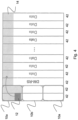
- FIGURE 6 illustrates an example of the puncturing of resources reused for data by one UE in the CORESET to transmit PDCCH for another UE, according to a particular embodiment.
- the illustrated example includes a transmission time interval comprising a plurality of OFDM symbols 42, control resource regions 10, control channels 12 and 16, and data transmission regions 14 and 18, similar to those described above.
- Two UEs receiving control channels 12 and 16 e.g., PDCCHs 12 and 16
- scheduled data e.g., data transmission regions 14 and 18
- two control resource regions 10a e.g., CORESETs 10a
- Data transmission region 14 starts at the third OFDM symbol and continues to the end of the transmission time interval. Data transmission region 14 does not include time and frequency resources within control resource regions 10. Data transmission region 18 starts at the frst OFDM symbol and continues to the end of the transmission time interval. Data transmission region 138 includes time and frequency resources within control resource regions 10a and 10b. Within control resource region 10a, data transmission region 18 excludes control resource region 16, but does not exclude control resource region 12.
- a sixth group of embodiments include reuse of control region resources for data without any scheduled data outside of the control region.
- the entire data transmission is contained within one or more of the CORESETs configured to the UE.
- a UE may receive a PDCCH without any REs allocated for data in the region outside the CORESETs but with a field indicating reuse of control region resources for data.
- the UE may then receive data only in resources within the CORESET where the PDCCH was received and also possibly in the other configured CORESETs depending on what is indicated in the field in the control message transmitted by the gNB. This is illustrated in FIGURE 7 .
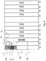
- FIGURE 7 illustrates an example of the reuse of resources in the CORESET for data transmission without any resource allocation for data transmission outside of the CORESET, according to a particular embodiment.
- the illustrated example includes a transmission time interval comprising a plurality of OFDM symbols 42, control resource regions 10, control channels 12 and 16, and data transmission regions 14 and 18, similar to those described above.
- a UE with PDCCH and a scheduled data transmission is illustrated as control channel 12 and data transmission region 14, respectively.
- Two UEs receiving control channels 12 and 16 e.g., PDCCHs 12 and 16
- scheduled data e.g., data transmission regions 14 and 18
- two control resource regions 10a e.g., CORESETs 10a
- Data transmission region 18 starts at the first OFDM symbol and continues to the end of the transmission time interval.
- Data transmission region 18 includes time and frequency resources within control resource regions 10a and 10b (excluding control channel region 16).
- Data transmission region 14 only includes time and frequency resources within control resource regions 10a (excluding time and frequency resources of control resource region 12.
- the gNB may configure multiple CORESETs to the UE for the express purpose of such data transmissions in some of the CORESETs which may be useful to serve traffic that needs to meet very low latency requirements and that may need to be sent in a particular slot even when there are other UEs that may be scheduled in that slot either via PDCCHs received in the same slot or from previous slots.
- modulation and coding scheme (MCS) to transport block size (TBS) mappings may be defined specifically for data transmissions that occur only in CORESETs as shown in the above figure.
- MCS modulation and coding scheme
- TBS transport block size
- Hybrid ARQ can be used for these transmissions with the HARQ IDs to be used for such data transmissions being sent in the DCI message.
- additional self-contained DMRS is included in the CORESET for the data transmission within the CORESET only.
- One nonlimiting embodiment is to insert DMRS patterns and locations consistent with those for the PDCCH.
- a seventh group of embodiments include reuse of control region resources for data without any scheduled data outside of the control region in the same symbol as PDCCH.
- the entire data transmission may be contained within one or more of the CORESETs configured to the UE.
- a UE may receive a PDCCH without any REs allocated for data in the region outside the CORESETs but with a field indicating reuse of control region resources for data in the same symbol as the one which PDCCH was found.
- FIGURE 8 An example is illustrated in FIGURE 8 .
- FIGURE 8 illustrates an example of the reuse of resources in the CORESET for data transmission without any resource allocation for data transmission outside of the CORESET in the symbol for which PDCCH was received in, according to a particular embodiment.
- the illustrated example includes a transmission time interval comprising a plurality of OFDM symbols 42, control resource regions 10, control channels 12 and 16, and data transmission regions 14 and 18, similar to those described above.
- a first UE with PDCCH and a scheduled data transmission is illustrated as control channel 12 and data transmission region 14, respectively.
- a second UE with PDCCH and a scheduled data transmission is illustrated as control channel 16 and data transmission region 18, respectively.
- Two UEs receiving PDCCHs e.g., control channels 12 and 16
- scheduled data e.g., data transmission regions 14 and 18
- two control resource regions 10a e.g., CORESETs 10a
- Data transmission region 14 consists of the first OFDM symbol and includes the bandwidth of control resource region 10a (excluding the time and frequency resources of control resource region 12).
- Data transmission region 18 consists of the second OFDM symbol and includes the bandwidth of control resource region 10a (excluding the time and frequency resources of control resource region 16).
- An eighth group of embodiments include joint encoding of starting time and control region reuse options.
- the frequency region may be split into a number of (possibly non-equally sized) regions. For each region, signaling informs the UE whether REs in that frequency region during the OFDM symbols spanned by a CORESET should be excluded from a resource allocation or not. It has some similarity with the first group of embodiments, but instead of excluding a CORESET, regions indicated by the gNB are excluded.
- One benefit is that the gNB can signal to the UE to exclude also resources the gNB knows overlaps with other users" CORESETs.
- the frequency region can be split into four quarters, each 1 ⁇ 4 of the total bandwidth.
- a bitmap can be used to indicate whether a particular quarter is to be excluded from a resource allocation or not.
- a ninth group of embodiments include joint encoding of starting time and control region reuse options.
- a single field may be used to indicate the OFDM symbol at which data starts and how the control regions configured to the UE should be reused for data transmission.
- An example of the encoding for the values of such a single field is described below where three bits are used.
- CORESET refers to the control region where the PDCCH message is received.
- a tenth group of embodiments include explicit use of bit maps to indicate reuse of resources in the OFDM symbols spanning the control region. Specific groups of resources in the OFDM symbols spanning the control region where the configured CORESETs reside may be assigned separate bits to indicate whether these resources are part of the data allocation or not.
- the regions that may be assigned bits include the following:
- An eleventh group of embodiments include use of control resource set for uplink transmission.
- the entire data transmission may be contained within one or more CORESETs configured to the UE for uplink transmission.
- the entire data transmission is contained outside one or more or all CORESETs configured to the UE for uplink transmission.
- the DCI message in a previous slot the DCI message can schedule downlink transmission in the next slot starting from a symbol different from the first symbol in that slot.
- an uplink grant in the previous slot can indicate uplink transmission in the next slot prior to the downlink transmission.
- FIGURE 9 illustrates an example of the reuse of resources in the CORESET for uplink data without any resource allocation of data transmissions outside of the CORESET, according to a particular embodiment.
- the illustrated example includes a transmission time interval comprising a plurality of OFDM symbols, control resource regions 10, control channels 12, 16 and 20, and data transmission regions 14, 18 and 22.
- a network node such as network node 120 may use control resource regions 10 for sending control channels to a UE, such as wireless device 110.
- network node 120 may send control channel 12 to wireless device 110 to schedule an uplink transmission (e.g., PDCCH with DCI).
- a UE receiving control channel 20 in control resource region 10b reuses resources in the next control resource region 10b (e.g., CORESET 10b) (indicated by arrow 22) for uplink data (e.g., data transmission region 22) without any resources allocated for data transmissions outside of control resource region 10b (e.g., CORESET 10b).
- the UEs in slot n+1 receive the scheduling information in the previous slot n.
- control channel regions 12 and 16 include scheduling for slot n and slot n+1 (as illustrated by the arrows in FIGURE 9 ).
- the embodiments above may include multiple PDDCHs transmission for a UE as well as other transmissions such as broadcast channels and synchronization signal monitored by a UE in a control resource sets. All resources known to the UE that are used for something other than user data transmissions are considered as used resources in a control resource set.
- FIGURE 10 is a flow diagram illustrating an example method in a network node, according to some embodiments, In particular embodiments, one or more steps of FIGURE 10 may be performed by network node 120 of wireless network 100 described with respect to FIGURE 1 .
- the method begins at step 1062, where the network node determines one or more control resource regions for a carrier.
- network node 120 may determine one or more CORESETs (or any other suitable control resource) (e.g., control resource regions 10 illustrated with respect to FIGURES 2-9 ) on which it may transmit control information to one or more wireless devices 110,
- Network node 120 may determine control resource region 10 dynamically (e.g., such as receiving signaling or other communications from another component of network 100), or network node 120 may be provisioned or pre-configured with information about one or more control resource regions.
- the network node determines a control channel region in a first control resource region of the one or more control resource regions.
- network node 120 may determine a PDCCH (e.g., control channels 12, 16 or 18 illustrated with respect to FIGURES 2-9 ) in the control resource region for transmitting control information to wireless device 110.
- PDCCH e.g., control channels 12, 16 or 18 illustrated with respect to FIGURES 2-9
- the control channel may comprise a subset of the time and frequency resources that comprise the control resource region.
- the remaining time and frequency resources may be used for another control channel, used for data transmission, or unused.
- Network node 120 may determine the control channel region dynamically (e.g., such as receiving signaling or other communications from another component of network 100), or network node 120 may be provisioned or pre-configured with information about one or more control channel regions.
- the network node determines a data transmission region in at least one control resource region of the one or more control resource regions. For example, network node 120 may determine that control resource region 10 includes unused resources (i.e., resources not used for a control channel or for data transmission). Network node 120 may determine that some or all of these resources may be used for data transmission. In some embodiments, network node 120 may determine that some used resources (e.g., a control channel for a lower priority user or service may be punctured for higher priority data transmission).
- control resource region 10 includes unused resources (i.e., resources not used for a control channel or for data transmission).
- network node 120 may determine that some or all of these resources may be used for data transmission. In some embodiments, network node 120 may determine that some used resources (e.g., a control channel for a lower priority user or service may be punctured for higher priority data transmission).
- the data transmission region comprises a subset of the resources in the at least one control resource region.
- An example is illustrated in FIGURE 2 where data transmission region 14 includes a subset of resources in control resource region 10a.
- the data transmission region may exclude resources for the control channel region.
- data transmission region 14 excludes control channel region 12.
- data transmission region 14 includes all the resources of control region 10a except for the resources used by control channel region 12.
- the data transmission region comprises resources within the at least one control resource region and resources outside of any of the one or more control resource regions.
- FIGURES 2-6 all illustrates data transmission regions 14 and/or 18 that includes resources both within and outside of control resource region 10.
- a frequency range of resources within the at least one control resource region may be the same as a frequency range of the resources outside of any of the one or more control resource regions (e.g., data transmission region 14 of FIGURE 2 ), or the frequency range may be different than the frequency range of the resources outside of any of the one or more control resource regions (e.g., data transmission region 14 of FIGURE 3 ).
- the data transmission region excludes resources outside of the at least one control resource region (e.g., data transmission region 14 of FIGURE 7 is included entirely within control resource region 10a).
- the data transmission region may comprise all resources in the at least one control resource region (e.g., data transmission region 18 of FIGURE 7 includes all the resources of control resource region 10b).
- the network node may determine the data transmission region according to any of the embodiments or examples described herein (e.g., with respect to FIGURES 2-9 ).
- the network node signals the determined data transmission region to a wireless device.
- network node 120 may signal the determined data transmission region to wireless device 110.
- the signaling may include a starting symbol and a number of symbols for data transmission.
- the signaling may include a frequency range.
- the signaling may include resource regions excluded from the data transmission region.
- the wireless device may determine the excluded regions implicitly based on predetermined rules or known control regions. In some embodiments, the network node may explicitly signal excluded resource regions.
- signaling the determined data transmission region to the wireless device comprises signaling a bitmap.
- the bitmap may indicate one or more groups of time and frequency resources used for the data transmission region, and/or one or more groups of time and frequency resources excluded from the data transmission region,
- signaling the determined data transmission region to the wireless device comprises signaling an identifier of at least one control resource region.
- the identifier of the at least one control resource region indicates a control resource region used for the data transmission region, and/or a control resource region excluded from the data transmission region.
- the network node may signal the data transmission region according to any of the embodiments or examples described herein (e.g., with respect to FIGURES 2-9 ).
- method 1000 Modifications, additions, or omissions may be made to method 1000. Additionally, one or more steps in method 100 of FIGURE 1 may be performed in parallel or in any suitable order. The steps of method 1000 may be repeated over time as necessary.
- FIGURE 11 is a flow diagram illustrating an example method in a wireless device, according to some embodiments. In particular embodiments, one or more steps of FIGURE 11 may be performed by wireless device 110 of wireless network 100 described with respect to FIGURE 1 .
- the method begins at step 1162, where the wireless device receives a control channel that includes control information that indicates a set of time and frequency resources allocated for the wireless device to receive a data transmission.
- wireless device 110 may receive a control channel (e.g., PDCCH) from network node 120).
- a control channel e.g., PDCCH
- the wireless device determines that the set of time and frequency resources allocated for data transmission overlaps with a control resource region. For example, wireless device 110 may determine that a data transmission region includes resources of one or more control resource regions 10,
- the data transmission region comprises a subset of the resources in the at least one control resource region.
- An example is illustrated in FIGURE 2 where data transmission region 14 includes a subset of resources in control resource region 10a.
- the data transmission region may exclude resources for the control channel region.
- data transmission region 14 excludes control channel region 12.
- data transmission region 14 includes all the resources of control region 10a except for the resources used by control channel region 12.
- the data transmission region comprises resources within the at least one control resource region and resources outside of any of the one or more control resource regions.
- FIGURES 2-6 all illustrates data transmission regions 14 and/or 18 that includes resources both within and outside of control resource region 10.
- a frequency range of resources within the at least one control resource region may be the same as a frequency range of the resources outside of any of the one or more control resource regions (e.g., data transmission region 14 of FIGURE 2 ), or the frequency range may be different than the frequency range of the resources outside of any of the one or more control resource regions (e.g., data transmission region 14 of FIGURE 3 ).
- the data transmission region excludes resources outside of the at least one control resource region (e.g., data transmission region 14 of FIGURE 7 is included entirely within control resource region 10a).
- the data transmission region may comprise all resources in the at least one control resource region (e.g., data transmission region 18 of FIGURE 7 includes all the resources of control resource region 10b).
- the network node may determine the data transmission region according to any of the embodiments or examples described herein (e.g., with respect to FIGURES 2-9 ).
- the wireless device may determine that particular regions of the data transmission are excluded implicitly based on predetermined rules or known control regions.
- network node 120 may explicitly signal excluded resource regions to wireless device 110.
- network node 120 may signal the determined data transmission region to wireless device 110 with a bitmap.
- the bitmap may indicate one or more groups of time and frequency resources used for the data transmission region, and/or one or more groups of time and frequency resources excluded from the data transmission region.
- Processing circuitry 1020 includes any suitable combination of hardware and software implemented in one or more integrated circuits or modules to execute instructions and manipulate data to perform some or all of the described functions of the wireless device.
- processing circuitry 1020 may include, for example, one or more computers, one more programmable logic devices, one or more central processing units (CPUs), one or more microprocessors, one or more applications, and/or other logic, and/or any suitable combination of the preceding.
- Processing circuitry 1020 may include analog and/or digital circuitry configured to perform some or all of the described functions of wireless device 110.
- processing circuitry 1020 may include resistors, capacitors, inductors, transistors, diodes, and/or any other suitable circuit components. Processing circuitry 1020 may perform any of the steps of the method claims below.
- FIGURE 12B is a block diagram illustrating example components of a wireless device 110.
- the components may include receiving module 1050 and determining module 1052.
- Network node 120 can be an eNodeB, a nodeB, a base station, a wireless access point (e.g., a Wi-Fi access point), a low power node, a base transceiver station (BTS), a transmission point or node, a remote RF unit (RRU), a remote radio head (RRH), or other radio access node.
- the network node includes at least one transceiver 1110, processing circuitry 1120, at least one memory 1130, and at least one network interface 1140.
- Transceiver 1110 facilitates transmitting wireless signals to and receiving wireless signals from a wireless device, such as wireless devices 110 (e.g., via an antenna); processing circuitry 1120 executes instructions to provide some or all of the functionality described above as being provided by a network node 120; memory 1130 stores the instructions executed by processing circuitry 1120; and network interface 1140 communicates signals to backend network components, such as a gateway, switch, router, Internet, Public Switched Telephone Network (PSTN), controller, and/or other network nodes 120, Processing circuitry 1120 and memory 1130 can be of the same types as described with respect to processing circuitry 1020 and memory 1030 of FIGURE 12A above. Processing circuitry 1120 may perform any of the steps of the method claims below.
- PSTN Public Switched Telephone Network
- network interface 1140 is communicatively coupled to processing circuitry 1120 and refers to any suitable device operable to receive input for network node 120, send output from network node 120, perform suitable processing of the input or output or both, communicate to other devices, or any combination of the preceding.
- Network interface 1140 includes appropriate hardware (e.g., port, modern, network interface card, etc.) and software, including protocol conversion and data processing capabilities, to communicate through a network.
- processing circuitry 1120 in communication with transceiver 1110 communicates user data within a control resource region (e.g, CORESET).
- a control resource region e.g, CORESET
- network node 120 includes additional components (beyond those shown in FIGURE 13A ) responsible for providing certain aspects of the network node's functionality, including any of the functionality described above and/or any additional functionality (including any functionality necessary to support the solution described above).
- the various different types of network nodes may include components having the same physical hardware but configured (e.g., via programming) to support different radio access technologies, or may represent partly or entirely different physical components.
- FIGURE 13B is a block diagram illustrating example components of a network node 120.
- the components may include determining module 1150 and signaling module 1152.
- Determining module 1150 may perform the determining functions of network node 120. For example, determining module 1150 may determine one or more control resource regions for a carrier, determine a control channel region in a first control resource region of the one or more control resource regions, and determine a data transmission region in at least one control resource region of the one or more control resource regions. Determining module 1150 may perform the determining functions according to any of the examples and embodiments described above (e.g., step 1062-1066 of FIGURE 1 ). In certain embodiments, determining module 1150 may include or be included in processing circuitry 1120. In particular embodiments, determining module 1150 may communicate with signaling module 1152.
- Signaling module 1152 may perform the signaling functions of network node 120. For example, signaling module 1152 may signal the determined data transmission region to a wireless device, according to any of the embodiments and examples described herein (e.g., step 1068 of FIGURE 10 ). In certain embodiments, signaling module 1152 may include or be included in processing circuitry 1120. In particular embodiments, signaling module 1152 may communicate with determining module 1150.
Landscapes
- Engineering & Computer Science (AREA)
- Signal Processing (AREA)
- Computer Networks & Wireless Communication (AREA)
- Mobile Radio Communication Systems (AREA)
- Design And Manufacture Of Integrated Circuits (AREA)
Claims (11)
- Verfahren in einer drahtlosen Vorrichtung (110), wobei das Verfahren Folgendes umfasst:Empfangen (1162) eines physischen Downlink-Steuerkanals (physical downlink control channel - PDCCH) von einem Netzwerkknoten (120), wobei der PDCCH Downlink-Steuerinformationen (downlink control information - DCI) beinhaltet, die einen Satz von Zeit- und Frequenzressourcen angeben, die der drahtlosen Vorrichtung zum Empfangen einer Datenübertragung zugewiesen sind, wobei der Satz (i) einen ersten Teilsatz (14) des angegebenen Satzes von der Datenübertragung zugewiesenen Zeit- und Frequenzressourcen, der sich mit Zeit- und Frequenzressourcen in einem oder mehreren Steuerressourcensätzen (CORESETs) (10a) überlappt, und (ii) einen zweiten Teilsatz (12) von Zeit- und Frequenzressourcen aus dem einen oder den mehreren CORESETs, die für die Datenübertragung ausgeschlossen sind, umfasst; undEmpfangen (1166) der Datenübertragung in dem ersten Teilsatz von Zeit- und Frequenzressourcen, die der Datenübertragung zugewiesen sind.
- Verfahren in einem Netzwerkknoten (120), wobei das Verfahren Folgendes umfasst:Bestimmen (1062) eines physischen Downlink-Steuerkanals (physical downlink control channel - PDCCH), wobei der PDCCH Downlink-Steuerinformationen (downlink control information - DCI) beinhaltet, die einen Satz von Zeit- und Frequenzressourcen angeben, die einer drahtlosen Vorrichtung (110) zum Empfangen einer Datenübertragung zugewiesen sind, wobei der Satz (i) einen ersten Teilsatz (14) des angegebenen Satzes von der Datenübertragung zugewiesenen Zeit- und Frequenzressourcen, der sich mit Zeit- und Frequenzressourcen in einem oder mehreren Steuerressourcensätzen (CORESETs) (10a) überlappt, und (ii) einen zweiten Teilsatz (12) von Zeit- und Frequenzressourcen aus dem einen oder den mehreren CORESETs, die für die Datenübertragung ausgeschlossen sind, umfasst; undÜbertragen (1068) des PDCCH an die drahtlose Vorrichtung.
- Verfahren nach Anspruch 1 oder 2, wobei der Satz von Zeit- und Frequenzressourcen, die der Datenübertragung zugewiesen sind, Ressourcen innerhalb des CORESET und Ressourcen außerhalb von beliebigen CORESETs umfasst.
- Verfahren nach Anspruch 3, wobei ein Frequenzbereich der Ressourcen innerhalb des CORESET derselbe ist wie ein Frequenzbereich der Ressourcen außerhalb des CORESET.
- Verfahren nach Anspruch 3, wobei sich ein Frequenzbereich der Ressourcen innerhalb des CORESET von einem Frequenzbereich der Ressourcen außerhalb des CORESET unterscheidet.
- Verfahren nach Anspruch 1 oder 2, wobei der Satz von Zeit- und Frequenzressourcen, die der Datenübertragung zugewiesen sind, Ressourcen außerhalb des CORESET ausschließt.
- Verfahren nach Anspruch 1 oder 2, wobei der Satz von Zeit- und Frequenzressourcen, die der Datenübertragung zugewiesen sind, alle Ressourcen in dem CORESET umfasst.
- Verfahren nach einem der Ansprüche 1 bis 7, wobei die DCI ferner eine Bitmap beinhalten und die Bitmap Folgendes angibt:eine oder mehrere Gruppen von Zeit- und Frequenzressourcen, die für die Datenübertragungsregion verwendet werden; undeine oder mehrere Gruppen von Zeit- und Frequenzressourcen, die aus der Datenübertragungsregion ausgeschlossen sind.
- Drahtlose Vorrichtung (110), umfassend einen Verarbeitungsschaltkreis (1020), wobei der Verarbeitungsschaltkreis betreibbar ist, um alle Schritte eines Verfahrens nach Anspruch 1 und einem der Ansprüche 3 bis 8 in Abhängigkeit von Anspruch 1 durchzuführen.
- Netzwerkknoten (120), umfassend den Verarbeitungsschaltkreis (1120), wobei der Verarbeitungsschaltkreis betreibbar ist, um das Verfahren nach Anspruch 2 und einem der Ansprüche 3 bis 8 in Abhängigkeit von Anspruch 2 durchzuführen.
- Computerlesbares Medium (1030, 1130), umfassend Codeabschnitte, die:wenn sie auf einem Verarbeitungsschaltkreis (1020) einer drahtlosen Vorrichtung (110) ausgeführt werden, den Verarbeitungsschaltkreis konfigurieren, um die Schritte eines Verfahrens nach einem der Ansprüche 1 oder einem der Ansprüche 3 bis 8 in Abhängigkeit von Anspruch 1 durchzuführen; oderwenn sie auf einer Verarbeitungsschaltung (1120) eines Netzwerkknotens (120) ausgeführt werden, die Verarbeitungsschaltung konfigurieren, um die Schritte eines Verfahrens nach einem der Ansprüche 2 oder einem der Ansprüche 3 bis 8 in Abhängigkeit von Anspruch 2 durchzuführen.
Priority Applications (1)
| Application Number | Priority Date | Filing Date | Title |
|---|---|---|---|
| EP25186456.7A EP4637071A3 (de) | 2017-02-06 | 2018-02-06 | Datenübertragung in kontrollbereichen |
Applications Claiming Priority (4)
| Application Number | Priority Date | Filing Date | Title |
|---|---|---|---|
| US201762455508P | 2017-02-06 | 2017-02-06 | |
| EP22180176.4A EP4099604B1 (de) | 2017-02-06 | 2018-02-06 | Datenübertragungen in steuerregionen |
| EP18705988.6A EP3577831B1 (de) | 2017-02-06 | 2018-02-06 | Datenübertragungen in steuerregionen |
| PCT/IB2018/050739 WO2018142377A1 (en) | 2017-02-06 | 2018-02-06 | Data transmissions in control regions |
Related Parent Applications (2)
| Application Number | Title | Priority Date | Filing Date |
|---|---|---|---|
| EP22180176.4A Division EP4099604B1 (de) | 2017-02-06 | 2018-02-06 | Datenübertragungen in steuerregionen |
| EP18705988.6A Division EP3577831B1 (de) | 2017-02-06 | 2018-02-06 | Datenübertragungen in steuerregionen |
Related Child Applications (1)
| Application Number | Title | Priority Date | Filing Date |
|---|---|---|---|
| EP25186456.7A Division EP4637071A3 (de) | 2017-02-06 | 2018-02-06 | Datenübertragung in kontrollbereichen |
Publications (3)
| Publication Number | Publication Date |
|---|---|
| EP4262129A1 EP4262129A1 (de) | 2023-10-18 |
| EP4262129B1 true EP4262129B1 (de) | 2025-07-09 |
| EP4262129C0 EP4262129C0 (de) | 2025-07-09 |
Family
ID=61244656
Family Applications (4)
| Application Number | Title | Priority Date | Filing Date |
|---|---|---|---|
| EP22180176.4A Active EP4099604B1 (de) | 2017-02-06 | 2018-02-06 | Datenübertragungen in steuerregionen |
| EP18705988.6A Active EP3577831B1 (de) | 2017-02-06 | 2018-02-06 | Datenübertragungen in steuerregionen |
| EP23177443.1A Active EP4262129B1 (de) | 2017-02-06 | 2018-02-06 | Datenübertragungen in steuerregionen |
| EP25186456.7A Pending EP4637071A3 (de) | 2017-02-06 | 2018-02-06 | Datenübertragung in kontrollbereichen |
Family Applications Before (2)
| Application Number | Title | Priority Date | Filing Date |
|---|---|---|---|
| EP22180176.4A Active EP4099604B1 (de) | 2017-02-06 | 2018-02-06 | Datenübertragungen in steuerregionen |
| EP18705988.6A Active EP3577831B1 (de) | 2017-02-06 | 2018-02-06 | Datenübertragungen in steuerregionen |
Family Applications After (1)
| Application Number | Title | Priority Date | Filing Date |
|---|---|---|---|
| EP25186456.7A Pending EP4637071A3 (de) | 2017-02-06 | 2018-02-06 | Datenübertragung in kontrollbereichen |
Country Status (9)
| Country | Link |
|---|---|
| US (2) | US11395279B2 (de) |
| EP (4) | EP4099604B1 (de) |
| JP (1) | JP7008077B2 (de) |
| KR (1) | KR102257554B1 (de) |
| CN (2) | CN110268670A (de) |
| BR (1) | BR112019016214A2 (de) |
| ES (2) | ES2924708T3 (de) |
| PL (1) | PL4099604T3 (de) |
| WO (1) | WO2018142377A1 (de) |
Families Citing this family (8)
| Publication number | Priority date | Publication date | Assignee | Title |
|---|---|---|---|---|
| KR102431635B1 (ko) | 2016-11-04 | 2022-08-12 | 삼성전자 주식회사 | 무선 셀룰라 통신 시스템에서 지연 감소를 위한 적응적 재전송 방법 및 장치 |
| US10512080B2 (en) * | 2017-03-17 | 2019-12-17 | Qualcomm Incorporated | MCS/rank adjustment when multiplexing data in a control region |
| MX2019013073A (es) * | 2017-05-02 | 2019-12-16 | Guangdong Oppo Mobile Telecommunications Corp Ltd | Metodos y aparatos para detectar canales de control en sistemas de comunicacion inalambrica. |
| CN109152020B (zh) * | 2017-06-16 | 2022-04-05 | 华为技术有限公司 | 一种数据接收方法、相关设备及系统 |
| US11271701B2 (en) * | 2018-01-12 | 2022-03-08 | Qualcomm Incorporated | Physical downlink control channel (PDCCH) monitoring with overlapping resources |
| WO2020041366A1 (en) * | 2018-08-20 | 2020-02-27 | Intel Corporation | Control resource set selection for channel state information reference signal-based radio link monitoring |
| CN111586857B (zh) * | 2019-02-15 | 2022-04-05 | 华为技术有限公司 | 参考信号的传输方法和通信装置 |
| WO2021088035A1 (zh) * | 2019-11-08 | 2021-05-14 | 华为技术有限公司 | 一种测量上报方法及装置 |
Family Cites Families (16)
| Publication number | Priority date | Publication date | Assignee | Title |
|---|---|---|---|---|
| US8442069B2 (en) * | 2008-04-14 | 2013-05-14 | Qualcomm Incorporated | System and method to enable uplink control for restricted association networks |
| CN101841851B (zh) * | 2009-03-18 | 2013-06-12 | 电信科学技术研究院 | 一种多小区传输数据的方法及装置 |
| US9622228B2 (en) * | 2009-05-04 | 2017-04-11 | Qualcomm Incorporated | Data and control multiplexing in wireless communications |
| CN101626625B (zh) * | 2009-08-05 | 2015-08-12 | 中兴通讯股份有限公司 | 一种下行载波控制域的实现方法 |
| US9237583B2 (en) * | 2010-05-03 | 2016-01-12 | Qualcomm Incorporated | Resource availability for PDSCH in relay backhaul transmissions |
| US9520975B2 (en) * | 2011-05-03 | 2016-12-13 | Telefonaktiebolaget Lm Ericsson (Publ) | Methods and devices for transmission of control data to a user equipment |
| CN102202400B (zh) * | 2011-05-31 | 2013-10-16 | 电信科学技术研究院 | 一种资源占用方式的指示及处理方法及装置 |
| ES2733945T3 (es) * | 2011-06-15 | 2019-12-03 | Samsung Electronics Co Ltd | Extensión de señalización de control de enlace descendente físico en un sistema de comunicaciones |
| WO2013055143A2 (ko) * | 2011-10-12 | 2013-04-18 | 엘지전자 주식회사 | 서브프레임에서 제어 채널의 탐색 영역을 할당하는 방법 및 장치 |
| US9602255B2 (en) * | 2011-10-13 | 2017-03-21 | Futurewei Technologies, Inc. | System and method for data channel transmission and reception |
| WO2014010996A1 (ko) * | 2012-07-12 | 2014-01-16 | 엘지전자 주식회사 | 무선 접속 시스템에서 장치 간 데이터 송수신을 위한 제어채널 할당 방법 및 이를 위한 장치 |
| GB2504544A (en) | 2012-08-02 | 2014-02-05 | Nec Corp | Resource allocation signalling within an enhanced Physical Downlink Control Channel (ePDCCH) |
| CN104769879B (zh) * | 2012-11-02 | 2018-11-20 | 华为技术有限公司 | 网络控制节点中的方法 |
| CN104661309A (zh) * | 2013-11-22 | 2015-05-27 | 中兴通讯股份有限公司 | Lte系统中多点协作网络的下行资源指示方法、装置及系统 |
| CN103702429B (zh) * | 2013-12-26 | 2017-11-07 | 上海无线通信研究中心 | 利用lte/lte‑a物理下行控制域闲置资源发送数据的方法 |
| KR102488966B1 (ko) * | 2017-09-08 | 2023-01-16 | 삼성전자 주식회사 | 무선 통신 시스템에서 제어채널 및 데이터채널을 송수신 하는 방법 및 장치 |
-
2018
- 2018-02-06 KR KR1020197025769A patent/KR102257554B1/ko active Active
- 2018-02-06 EP EP22180176.4A patent/EP4099604B1/de active Active
- 2018-02-06 US US16/483,779 patent/US11395279B2/en active Active
- 2018-02-06 ES ES18705988T patent/ES2924708T3/es active Active
- 2018-02-06 EP EP18705988.6A patent/EP3577831B1/de active Active
- 2018-02-06 BR BR112019016214A patent/BR112019016214A2/pt unknown
- 2018-02-06 JP JP2019539821A patent/JP7008077B2/ja active Active
- 2018-02-06 WO PCT/IB2018/050739 patent/WO2018142377A1/en not_active Ceased
- 2018-02-06 PL PL22180176.4T patent/PL4099604T3/pl unknown
- 2018-02-06 ES ES22180176T patent/ES2955340T3/es active Active
- 2018-02-06 EP EP23177443.1A patent/EP4262129B1/de active Active
- 2018-02-06 CN CN201880010463.2A patent/CN110268670A/zh active Pending
- 2018-02-06 CN CN202310582234.0A patent/CN116667986A/zh active Pending
- 2018-02-06 EP EP25186456.7A patent/EP4637071A3/de active Pending
-
2022
- 2022-06-13 US US17/838,515 patent/US12225545B2/en active Active
Also Published As
| Publication number | Publication date |
|---|---|
| ES2955340T3 (es) | 2023-11-30 |
| JP2020507265A (ja) | 2020-03-05 |
| US12225545B2 (en) | 2025-02-11 |
| EP3577831B1 (de) | 2022-06-22 |
| EP4637071A3 (de) | 2025-10-29 |
| CN116667986A (zh) | 2023-08-29 |
| EP4637071A2 (de) | 2025-10-22 |
| EP3577831A1 (de) | 2019-12-11 |
| BR112019016214A2 (pt) | 2020-04-07 |
| PL4099604T3 (pl) | 2023-11-27 |
| EP4099604B1 (de) | 2023-06-21 |
| KR102257554B1 (ko) | 2021-05-27 |
| CN110268670A (zh) | 2019-09-20 |
| KR20190108627A (ko) | 2019-09-24 |
| US20200029312A1 (en) | 2020-01-23 |
| EP4262129A1 (de) | 2023-10-18 |
| JP7008077B2 (ja) | 2022-02-10 |
| ES2924708T3 (es) | 2022-10-10 |
| EP4262129C0 (de) | 2025-07-09 |
| US11395279B2 (en) | 2022-07-19 |
| US20220377716A1 (en) | 2022-11-24 |
| EP4099604A1 (de) | 2022-12-07 |
| WO2018142377A1 (en) | 2018-08-09 |
Similar Documents
| Publication | Publication Date | Title |
|---|---|---|
| US12225545B2 (en) | Data transmissions in control regions | |
| US11147057B2 (en) | PDCCH monitoring periodicity | |
| US12010711B2 (en) | Signaling reference signal locations in slots and mini-slots | |
| US12089229B2 (en) | PDCCH monitoring periodicity | |
| CN110495126B (zh) | 用于NB-IoT的非锚定载波配置 | |
| KR20200018820A (ko) | 동일한 사이즈 코드 블록에 대한 전송 블록 사이즈 결정 | |
| OA19789A (en) | Non-anchor carrier configuration for NbIot. |
Legal Events
| Date | Code | Title | Description |
|---|---|---|---|
| PUAI | Public reference made under article 153(3) epc to a published international application that has entered the european phase |
Free format text: ORIGINAL CODE: 0009012 |
|
| STAA | Information on the status of an ep patent application or granted ep patent |
Free format text: STATUS: THE APPLICATION HAS BEEN PUBLISHED |
|
| AC | Divisional application: reference to earlier application |
Ref document number: 3577831 Country of ref document: EP Kind code of ref document: P Ref document number: 4099604 Country of ref document: EP Kind code of ref document: P |
|
| AK | Designated contracting states |
Kind code of ref document: A1 Designated state(s): AL AT BE BG CH CY CZ DE DK EE ES FI FR GB GR HR HU IE IS IT LI LT LU LV MC MK MT NL NO PL PT RO RS SE SI SK SM TR |
|
| STAA | Information on the status of an ep patent application or granted ep patent |
Free format text: STATUS: REQUEST FOR EXAMINATION WAS MADE |
|
| 17P | Request for examination filed |
Effective date: 20240410 |
|
| RBV | Designated contracting states (corrected) |
Designated state(s): AL AT BE BG CH CY CZ DE DK EE ES FI FR GB GR HR HU IE IS IT LI LT LU LV MC MK MT NL NO PL PT RO RS SE SI SK SM TR |
|
| GRAP | Despatch of communication of intention to grant a patent |
Free format text: ORIGINAL CODE: EPIDOSNIGR1 |
|
| STAA | Information on the status of an ep patent application or granted ep patent |
Free format text: STATUS: GRANT OF PATENT IS INTENDED |
|
| INTG | Intention to grant announced |
Effective date: 20250212 |
|
| GRAS | Grant fee paid |
Free format text: ORIGINAL CODE: EPIDOSNIGR3 |
|
| GRAA | (expected) grant |
Free format text: ORIGINAL CODE: 0009210 |
|
| STAA | Information on the status of an ep patent application or granted ep patent |
Free format text: STATUS: THE PATENT HAS BEEN GRANTED |
|
| AC | Divisional application: reference to earlier application |
Ref document number: 3577831 Country of ref document: EP Kind code of ref document: P Ref document number: 4099604 Country of ref document: EP Kind code of ref document: P |
|
| AK | Designated contracting states |
Kind code of ref document: B1 Designated state(s): AL AT BE BG CH CY CZ DE DK EE ES FI FR GB GR HR HU IE IS IT LI LT LU LV MC MK MT NL NO PL PT RO RS SE SI SK SM TR |
|
| REG | Reference to a national code |
Ref country code: GB Ref legal event code: FG4D |
|
| REG | Reference to a national code |
Ref country code: CH Ref legal event code: EP |
|
| REG | Reference to a national code |
Ref country code: IE Ref legal event code: FG4D |
|
| REG | Reference to a national code |
Ref country code: DE Ref legal event code: R096 Ref document number: 602018083556 Country of ref document: DE |
|
| U01 | Request for unitary effect filed |
Effective date: 20250709 |
|
| U07 | Unitary effect registered |
Designated state(s): AT BE BG DE DK EE FI FR IT LT LU LV MT NL PT RO SE SI Effective date: 20250715 |
|
| PG25 | Lapsed in a contracting state [announced via postgrant information from national office to epo] |
Ref country code: IS Free format text: LAPSE BECAUSE OF FAILURE TO SUBMIT A TRANSLATION OF THE DESCRIPTION OR TO PAY THE FEE WITHIN THE PRESCRIBED TIME-LIMIT Effective date: 20251109 |
|
| PG25 | Lapsed in a contracting state [announced via postgrant information from national office to epo] |
Ref country code: NO Free format text: LAPSE BECAUSE OF FAILURE TO SUBMIT A TRANSLATION OF THE DESCRIPTION OR TO PAY THE FEE WITHIN THE PRESCRIBED TIME-LIMIT Effective date: 20251009 |
|
| PG25 | Lapsed in a contracting state [announced via postgrant information from national office to epo] |
Ref country code: HR Free format text: LAPSE BECAUSE OF FAILURE TO SUBMIT A TRANSLATION OF THE DESCRIPTION OR TO PAY THE FEE WITHIN THE PRESCRIBED TIME-LIMIT Effective date: 20250709 |
|
| PG25 | Lapsed in a contracting state [announced via postgrant information from national office to epo] |
Ref country code: GR Free format text: LAPSE BECAUSE OF FAILURE TO SUBMIT A TRANSLATION OF THE DESCRIPTION OR TO PAY THE FEE WITHIN THE PRESCRIBED TIME-LIMIT Effective date: 20251010 |
|
| PG25 | Lapsed in a contracting state [announced via postgrant information from national office to epo] |
Ref country code: PL Free format text: LAPSE BECAUSE OF FAILURE TO SUBMIT A TRANSLATION OF THE DESCRIPTION OR TO PAY THE FEE WITHIN THE PRESCRIBED TIME-LIMIT Effective date: 20250709 |
|
| PG25 | Lapsed in a contracting state [announced via postgrant information from national office to epo] |
Ref country code: RS Free format text: LAPSE BECAUSE OF FAILURE TO SUBMIT A TRANSLATION OF THE DESCRIPTION OR TO PAY THE FEE WITHIN THE PRESCRIBED TIME-LIMIT Effective date: 20251009 |
|
| PG25 | Lapsed in a contracting state [announced via postgrant information from national office to epo] |
Ref country code: ES Free format text: LAPSE BECAUSE OF FAILURE TO SUBMIT A TRANSLATION OF THE DESCRIPTION OR TO PAY THE FEE WITHIN THE PRESCRIBED TIME-LIMIT Effective date: 20250709 |