EP4261471A1 - Air conditioning system and refrigerant state inspection method and device thereof - Google Patents
Air conditioning system and refrigerant state inspection method and device thereof Download PDFInfo
- Publication number
- EP4261471A1 EP4261471A1 EP21918938.8A EP21918938A EP4261471A1 EP 4261471 A1 EP4261471 A1 EP 4261471A1 EP 21918938 A EP21918938 A EP 21918938A EP 4261471 A1 EP4261471 A1 EP 4261471A1
- Authority
- EP
- European Patent Office
- Prior art keywords
- heat exchanger
- refrigerant
- temperature
- operating parameter
- pressure
- Prior art date
- Legal status (The legal status is an assumption and is not a legal conclusion. Google has not performed a legal analysis and makes no representation as to the accuracy of the status listed.)
- Granted
Links
Images




Classifications
-
- F—MECHANICAL ENGINEERING; LIGHTING; HEATING; WEAPONS; BLASTING
- F24—HEATING; RANGES; VENTILATING
- F24F—AIR-CONDITIONING; AIR-HUMIDIFICATION; VENTILATION; USE OF AIR CURRENTS FOR SCREENING
- F24F11/00—Control or safety arrangements
- F24F11/30—Control or safety arrangements for purposes related to the operation of the system, e.g. for safety or monitoring
- F24F11/32—Responding to malfunctions or emergencies
- F24F11/38—Failure diagnosis
-
- F—MECHANICAL ENGINEERING; LIGHTING; HEATING; WEAPONS; BLASTING
- F24—HEATING; RANGES; VENTILATING
- F24F—AIR-CONDITIONING; AIR-HUMIDIFICATION; VENTILATION; USE OF AIR CURRENTS FOR SCREENING
- F24F11/00—Control or safety arrangements
- F24F11/30—Control or safety arrangements for purposes related to the operation of the system, e.g. for safety or monitoring
- F24F11/32—Responding to malfunctions or emergencies
- F24F11/36—Responding to malfunctions or emergencies to leakage of heat-exchange fluid
-
- F—MECHANICAL ENGINEERING; LIGHTING; HEATING; WEAPONS; BLASTING
- F24—HEATING; RANGES; VENTILATING
- F24F—AIR-CONDITIONING; AIR-HUMIDIFICATION; VENTILATION; USE OF AIR CURRENTS FOR SCREENING
- F24F11/00—Control or safety arrangements
- F24F11/50—Control or safety arrangements characterised by user interfaces or communication
-
- F—MECHANICAL ENGINEERING; LIGHTING; HEATING; WEAPONS; BLASTING
- F24—HEATING; RANGES; VENTILATING
- F24F—AIR-CONDITIONING; AIR-HUMIDIFICATION; VENTILATION; USE OF AIR CURRENTS FOR SCREENING
- F24F11/00—Control or safety arrangements
- F24F11/62—Control or safety arrangements characterised by the type of control or by internal processing, e.g. using fuzzy logic, adaptive control or estimation of values
- F24F11/63—Electronic processing
- F24F11/64—Electronic processing using pre-stored data
-
- F—MECHANICAL ENGINEERING; LIGHTING; HEATING; WEAPONS; BLASTING
- F24—HEATING; RANGES; VENTILATING
- F24F—AIR-CONDITIONING; AIR-HUMIDIFICATION; VENTILATION; USE OF AIR CURRENTS FOR SCREENING
- F24F11/00—Control or safety arrangements
- F24F11/89—Arrangement or mounting of control or safety devices
-
- F—MECHANICAL ENGINEERING; LIGHTING; HEATING; WEAPONS; BLASTING
- F25—REFRIGERATION OR COOLING; COMBINED HEATING AND REFRIGERATION SYSTEMS; HEAT PUMP SYSTEMS; MANUFACTURE OR STORAGE OF ICE; LIQUEFACTION SOLIDIFICATION OF GASES
- F25B—REFRIGERATION MACHINES, PLANTS OR SYSTEMS; COMBINED HEATING AND REFRIGERATION SYSTEMS; HEAT PUMP SYSTEMS
- F25B13/00—Compression machines, plants or systems, with reversible cycle
-
- F—MECHANICAL ENGINEERING; LIGHTING; HEATING; WEAPONS; BLASTING
- F25—REFRIGERATION OR COOLING; COMBINED HEATING AND REFRIGERATION SYSTEMS; HEAT PUMP SYSTEMS; MANUFACTURE OR STORAGE OF ICE; LIQUEFACTION SOLIDIFICATION OF GASES
- F25B—REFRIGERATION MACHINES, PLANTS OR SYSTEMS; COMBINED HEATING AND REFRIGERATION SYSTEMS; HEAT PUMP SYSTEMS
- F25B49/00—Arrangement or mounting of control or safety devices
- F25B49/005—Arrangement or mounting of control or safety devices of safety devices
-
- F—MECHANICAL ENGINEERING; LIGHTING; HEATING; WEAPONS; BLASTING
- F25—REFRIGERATION OR COOLING; COMBINED HEATING AND REFRIGERATION SYSTEMS; HEAT PUMP SYSTEMS; MANUFACTURE OR STORAGE OF ICE; LIQUEFACTION SOLIDIFICATION OF GASES
- F25B—REFRIGERATION MACHINES, PLANTS OR SYSTEMS; COMBINED HEATING AND REFRIGERATION SYSTEMS; HEAT PUMP SYSTEMS
- F25B49/00—Arrangement or mounting of control or safety devices
- F25B49/02—Arrangement or mounting of control or safety devices for compression type machines, plants or systems
-
- F—MECHANICAL ENGINEERING; LIGHTING; HEATING; WEAPONS; BLASTING
- F24—HEATING; RANGES; VENTILATING
- F24F—AIR-CONDITIONING; AIR-HUMIDIFICATION; VENTILATION; USE OF AIR CURRENTS FOR SCREENING
- F24F2110/00—Control inputs relating to air properties
- F24F2110/10—Temperature
- F24F2110/12—Temperature of the outside air
-
- F—MECHANICAL ENGINEERING; LIGHTING; HEATING; WEAPONS; BLASTING
- F25—REFRIGERATION OR COOLING; COMBINED HEATING AND REFRIGERATION SYSTEMS; HEAT PUMP SYSTEMS; MANUFACTURE OR STORAGE OF ICE; LIQUEFACTION SOLIDIFICATION OF GASES
- F25B—REFRIGERATION MACHINES, PLANTS OR SYSTEMS; COMBINED HEATING AND REFRIGERATION SYSTEMS; HEAT PUMP SYSTEMS
- F25B2500/00—Problems to be solved
- F25B2500/19—Calculation of parameters
-
- F—MECHANICAL ENGINEERING; LIGHTING; HEATING; WEAPONS; BLASTING
- F25—REFRIGERATION OR COOLING; COMBINED HEATING AND REFRIGERATION SYSTEMS; HEAT PUMP SYSTEMS; MANUFACTURE OR STORAGE OF ICE; LIQUEFACTION SOLIDIFICATION OF GASES
- F25B—REFRIGERATION MACHINES, PLANTS OR SYSTEMS; COMBINED HEATING AND REFRIGERATION SYSTEMS; HEAT PUMP SYSTEMS
- F25B2500/00—Problems to be solved
- F25B2500/22—Preventing, detecting or repairing leaks of refrigeration fluids
- F25B2500/222—Detecting refrigerant leaks
-
- F—MECHANICAL ENGINEERING; LIGHTING; HEATING; WEAPONS; BLASTING
- F25—REFRIGERATION OR COOLING; COMBINED HEATING AND REFRIGERATION SYSTEMS; HEAT PUMP SYSTEMS; MANUFACTURE OR STORAGE OF ICE; LIQUEFACTION SOLIDIFICATION OF GASES
- F25B—REFRIGERATION MACHINES, PLANTS OR SYSTEMS; COMBINED HEATING AND REFRIGERATION SYSTEMS; HEAT PUMP SYSTEMS
- F25B2700/00—Sensing or detecting of parameters; Sensors therefor
- F25B2700/17—Speeds
- F25B2700/171—Speeds of the compressor
-
- F—MECHANICAL ENGINEERING; LIGHTING; HEATING; WEAPONS; BLASTING
- F25—REFRIGERATION OR COOLING; COMBINED HEATING AND REFRIGERATION SYSTEMS; HEAT PUMP SYSTEMS; MANUFACTURE OR STORAGE OF ICE; LIQUEFACTION SOLIDIFICATION OF GASES
- F25B—REFRIGERATION MACHINES, PLANTS OR SYSTEMS; COMBINED HEATING AND REFRIGERATION SYSTEMS; HEAT PUMP SYSTEMS
- F25B2700/00—Sensing or detecting of parameters; Sensors therefor
- F25B2700/19—Pressures
- F25B2700/193—Pressures of the compressor
- F25B2700/1931—Discharge pressures
-
- F—MECHANICAL ENGINEERING; LIGHTING; HEATING; WEAPONS; BLASTING
- F25—REFRIGERATION OR COOLING; COMBINED HEATING AND REFRIGERATION SYSTEMS; HEAT PUMP SYSTEMS; MANUFACTURE OR STORAGE OF ICE; LIQUEFACTION SOLIDIFICATION OF GASES
- F25B—REFRIGERATION MACHINES, PLANTS OR SYSTEMS; COMBINED HEATING AND REFRIGERATION SYSTEMS; HEAT PUMP SYSTEMS
- F25B2700/00—Sensing or detecting of parameters; Sensors therefor
- F25B2700/19—Pressures
- F25B2700/193—Pressures of the compressor
- F25B2700/1933—Suction pressures
-
- F—MECHANICAL ENGINEERING; LIGHTING; HEATING; WEAPONS; BLASTING
- F25—REFRIGERATION OR COOLING; COMBINED HEATING AND REFRIGERATION SYSTEMS; HEAT PUMP SYSTEMS; MANUFACTURE OR STORAGE OF ICE; LIQUEFACTION SOLIDIFICATION OF GASES
- F25B—REFRIGERATION MACHINES, PLANTS OR SYSTEMS; COMBINED HEATING AND REFRIGERATION SYSTEMS; HEAT PUMP SYSTEMS
- F25B2700/00—Sensing or detecting of parameters; Sensors therefor
- F25B2700/19—Pressures
- F25B2700/195—Pressures of the condenser
-
- F—MECHANICAL ENGINEERING; LIGHTING; HEATING; WEAPONS; BLASTING
- F25—REFRIGERATION OR COOLING; COMBINED HEATING AND REFRIGERATION SYSTEMS; HEAT PUMP SYSTEMS; MANUFACTURE OR STORAGE OF ICE; LIQUEFACTION SOLIDIFICATION OF GASES
- F25B—REFRIGERATION MACHINES, PLANTS OR SYSTEMS; COMBINED HEATING AND REFRIGERATION SYSTEMS; HEAT PUMP SYSTEMS
- F25B2700/00—Sensing or detecting of parameters; Sensors therefor
- F25B2700/21—Temperatures
- F25B2700/2103—Temperatures near a heat exchanger
-
- F—MECHANICAL ENGINEERING; LIGHTING; HEATING; WEAPONS; BLASTING
- F25—REFRIGERATION OR COOLING; COMBINED HEATING AND REFRIGERATION SYSTEMS; HEAT PUMP SYSTEMS; MANUFACTURE OR STORAGE OF ICE; LIQUEFACTION SOLIDIFICATION OF GASES
- F25B—REFRIGERATION MACHINES, PLANTS OR SYSTEMS; COMBINED HEATING AND REFRIGERATION SYSTEMS; HEAT PUMP SYSTEMS
- F25B2700/00—Sensing or detecting of parameters; Sensors therefor
- F25B2700/21—Temperatures
- F25B2700/2106—Temperatures of fresh outdoor air
-
- F—MECHANICAL ENGINEERING; LIGHTING; HEATING; WEAPONS; BLASTING
- F25—REFRIGERATION OR COOLING; COMBINED HEATING AND REFRIGERATION SYSTEMS; HEAT PUMP SYSTEMS; MANUFACTURE OR STORAGE OF ICE; LIQUEFACTION SOLIDIFICATION OF GASES
- F25B—REFRIGERATION MACHINES, PLANTS OR SYSTEMS; COMBINED HEATING AND REFRIGERATION SYSTEMS; HEAT PUMP SYSTEMS
- F25B2700/00—Sensing or detecting of parameters; Sensors therefor
- F25B2700/21—Temperatures
- F25B2700/2115—Temperatures of a compressor or the drive means therefor
- F25B2700/21151—Temperatures of a compressor or the drive means therefor at the suction side of the compressor
-
- F—MECHANICAL ENGINEERING; LIGHTING; HEATING; WEAPONS; BLASTING
- F25—REFRIGERATION OR COOLING; COMBINED HEATING AND REFRIGERATION SYSTEMS; HEAT PUMP SYSTEMS; MANUFACTURE OR STORAGE OF ICE; LIQUEFACTION SOLIDIFICATION OF GASES
- F25B—REFRIGERATION MACHINES, PLANTS OR SYSTEMS; COMBINED HEATING AND REFRIGERATION SYSTEMS; HEAT PUMP SYSTEMS
- F25B2700/00—Sensing or detecting of parameters; Sensors therefor
- F25B2700/21—Temperatures
- F25B2700/2115—Temperatures of a compressor or the drive means therefor
- F25B2700/21152—Temperatures of a compressor or the drive means therefor at the discharge side of the compressor
-
- F—MECHANICAL ENGINEERING; LIGHTING; HEATING; WEAPONS; BLASTING
- F25—REFRIGERATION OR COOLING; COMBINED HEATING AND REFRIGERATION SYSTEMS; HEAT PUMP SYSTEMS; MANUFACTURE OR STORAGE OF ICE; LIQUEFACTION SOLIDIFICATION OF GASES
- F25B—REFRIGERATION MACHINES, PLANTS OR SYSTEMS; COMBINED HEATING AND REFRIGERATION SYSTEMS; HEAT PUMP SYSTEMS
- F25B2700/00—Sensing or detecting of parameters; Sensors therefor
- F25B2700/21—Temperatures
- F25B2700/2116—Temperatures of a condenser
- F25B2700/21161—Temperatures of a condenser of the fluid heated by the condenser
-
- F—MECHANICAL ENGINEERING; LIGHTING; HEATING; WEAPONS; BLASTING
- F25—REFRIGERATION OR COOLING; COMBINED HEATING AND REFRIGERATION SYSTEMS; HEAT PUMP SYSTEMS; MANUFACTURE OR STORAGE OF ICE; LIQUEFACTION SOLIDIFICATION OF GASES
- F25B—REFRIGERATION MACHINES, PLANTS OR SYSTEMS; COMBINED HEATING AND REFRIGERATION SYSTEMS; HEAT PUMP SYSTEMS
- F25B2700/00—Sensing or detecting of parameters; Sensors therefor
- F25B2700/21—Temperatures
- F25B2700/2116—Temperatures of a condenser
- F25B2700/21162—Temperatures of a condenser of the refrigerant at the inlet of the condenser
-
- F—MECHANICAL ENGINEERING; LIGHTING; HEATING; WEAPONS; BLASTING
- F25—REFRIGERATION OR COOLING; COMBINED HEATING AND REFRIGERATION SYSTEMS; HEAT PUMP SYSTEMS; MANUFACTURE OR STORAGE OF ICE; LIQUEFACTION SOLIDIFICATION OF GASES
- F25B—REFRIGERATION MACHINES, PLANTS OR SYSTEMS; COMBINED HEATING AND REFRIGERATION SYSTEMS; HEAT PUMP SYSTEMS
- F25B2700/00—Sensing or detecting of parameters; Sensors therefor
- F25B2700/21—Temperatures
- F25B2700/2116—Temperatures of a condenser
- F25B2700/21163—Temperatures of a condenser of the refrigerant at the outlet of the condenser
-
- Y—GENERAL TAGGING OF NEW TECHNOLOGICAL DEVELOPMENTS; GENERAL TAGGING OF CROSS-SECTIONAL TECHNOLOGIES SPANNING OVER SEVERAL SECTIONS OF THE IPC; TECHNICAL SUBJECTS COVERED BY FORMER USPC CROSS-REFERENCE ART COLLECTIONS [XRACs] AND DIGESTS
- Y02—TECHNOLOGIES OR APPLICATIONS FOR MITIGATION OR ADAPTATION AGAINST CLIMATE CHANGE
- Y02B—CLIMATE CHANGE MITIGATION TECHNOLOGIES RELATED TO BUILDINGS, e.g. HOUSING, HOUSE APPLIANCES OR RELATED END-USER APPLICATIONS
- Y02B30/00—Energy efficient heating, ventilation or air conditioning [HVAC]
- Y02B30/70—Efficient control or regulation technologies, e.g. for control of refrigerant flow, motor or heating
Definitions
- the present disclosure relates to the technical field of air conditioning, and more particularly, relates to an air conditioning system, and a method for detecting a refrigerant state and apparatus thereof.
- air conditioners are more and more popular in people's daily production and work and life, and people are putting more and more emphasis on the safety requirements of air conditioners, including the detection of refrigerant leakage.
- the refrigerant state of an air conditioning system is difficult to determine due to the complex installation conditions of the air conditioning system, the variability of operating conditions and use conditions.
- the refrigerant state determination is a key for determination of the operation state of the air conditioning system and is also a basis for determination of refrigerant leakage.
- One objective of the embodiments of the present disclosure is to provide an air conditioning system and a method for detecting a refrigerant state and apparatus thereof, which may accurately obtain the refrigerant state of the air conditioning system according to the operating parameter of the air conditioning system, thereby improving the safety and reliability of the air conditioning system during use.
- a first aspect of the embodiments of the present disclosure provides a method for detecting a refrigerant state, comprising:
- a second aspect of the embodiments of the present disclosure provides an apparatus for detecting a refrigerant state, including:
- a third aspect of the embodiments of the present disclosure provides an air conditioning system, including a memory, a processor and a computer program stored in the memory and executable on the processor, the processor implements steps of the method for detecting a refrigerant state according to the first aspect of the embodiments of the present disclosure when executing the computer program.
- a fourth aspect of the embodiments of the present disclosure provides a computer-readable storage medium storing a computer program, which, when executed by a processor, implements steps of the method for detecting a refrigerant state according to the first aspect of the embodiments of the present disclosure.
- the method for detecting a refrigerant state may accurately obtain the refrigerant state of an air conditioning system according to the operating parameter of the air conditioning system, and improve the safety and reliability of the air conditioning system during use, by adjusting the first operating parameter of the air conditioning system; where the first operating parameter includes a frequency of a compressor, a wind speed setting, and an opening degree of an electronic expansion valve; collecting the second operating parameter of the air conditioning system after the adjustment of the first operating parameter has been completed for a preset duration; where the second operating parameter include an outdoor environment temperature and operating parameter of the compressor; and determining the refrigerant state of the air conditioning system according to the second operating parameter.
- the term “if” may be construed to mean “when” or “upon” or “in response to determining” or “in response to detecting,” depending on the context.
- the phrase “if it is determined” or “if [a stated condition or event] is detected” may be construed to mean “upon determining” or “in response to determining” or “upon detecting [the stated condition or event]” or “in response to detecting [the stated condition or event],” depending on the context.
- the embodiments of this disclosure provide a method for detecting a refrigerant state, which may be executed by a processor of an air conditioning system when running a corresponding computer program.
- the air conditioning system may be a stand-alone air conditioning system, or may be a multi-unit air conditioning system.
- the stand-alone air conditioning system and the multi-unit air conditioning system may be cooling-only systems for cooling only.
- an air conditioning system may include, but is not limited to, a memory, a processor, and a compressor, a heat exchanger, an electronic expansion valve, a pressure sensor, a temperature sensor, etc. which are connected to the processor, and may further include an oil separator, a four-way valve, a gas-liquid separator, an economizer, an evaporator, and pipelines connecting the components, and the like.
- the air conditioning system described in the embodiments of this disclosure does not constitute a limitation on the air conditioning system, and the air conditioning system may include more or fewer components, or some components, or different component arrangements.
- FIG. 2 a schematic diagram of a structural of an air conditioning system that includes an economizer is shown as an example, in which the air conditioning system further includes an economizer 70 in addition to those shown in FIG. 1 .
- An inlet of the economizer 70 is connected to the high-pressure liquid pipe 41 through an input pipe, which is provided with a second electronic expansion valve 71 and an economizer inlet temperature sensor 72.
- An outlet of the economizer 70 is connected to the compressor 10 through an output pipe, which is provided with an economizer outlet temperature sensor 73.
- the method for detecting a refrigerant state for an air conditioning system includes the following steps S301 to S303: At step S301, adjust first operating parameter of the air conditioning system, where the first operating parameter include a frequency of the compressor, a wind speed setting, and an opening degree of the electronic expansion valve.
- the refrigerant state detection may be immediately and automatically performed after the air conditioning system is powered on, or may be performed automatically at any time when a user needs to after the air conditioning system is powered on.
- the air conditioning system may be powered on when receiving a starting instruction sent by the user and adjust the first operating parameter of the air conditioning system to specified values; and may also adjust the first operating parameter of the air conditioning system to the specified values when receiving the refrigerant state detection instruction sent by the user after the air conditioning system is power on.
- the first operating parameter includes the frequency of the compressor of the outdoor unit of the air conditioning system, the wind speed setting of the outdoor unit, and the opening degree of the electronic expansion valve of the outdoor unit.
- the electronic expansion valve may be the electronic expansion valve of the outdoor unit, for example, the first electronic expansion valve 43 shown in FIG. 1 ; in case where the air conditioning system includes an economizer, the electronic expansion valves may include both the electronic expansion valve of the outdoor unit and an electronic expansion valve of the economizer, for example, the first electronic expansion valve 43 and the second electronic expansion valve 71 shown in FIG. 2 .
- step S302 collect a second operating parameter of the air conditioning system after the adjustment of the first operating parameter has been completed for a preset duration, where the second operating parameter includes an outdoor environment temperature and an operating parameter of the compressor.
- step S303 determine a refrigerant state of the air conditioning system according to the second operating parameter.
- the second operating parameter of the air conditioning system may be collected after the adjustment of the first operating parameter has been completed for a preset duration to enable the air conditioning system to stably operate in the refrigerant state detection mode, and the refrigerant state of the air conditioning system may be determined according to the second operating parameter.
- the preset duration may be customized by the user according to actual needs or use a value from the factory default settings, as long as the air conditioning system may stably operate after entering the refrigerant state detection mode for the preset duration.
- the outdoor environment temperature is the temperature of the outdoor environment where the outdoor unit is located, and may be detected by a temperature sensor positioned outdoors, for example, the outdoor environment temperature sensor 47 shown in FIG. 1 or FIG. 2 .
- the operating parameter of the compressor may include, but are not limited to, the frequency of the compressor, an exhaust pressure, a return air pressure, a return air temperature, an exhaust temperature, and the like.
- the exhaust pressure, the return air pressure, the return air temperature, and the exhaust temperature of the compressor may be detected by respective pressure sensors and temperature sensors, such as the exhaust pressure sensor 12, the return air pressure sensor 15, the return air temperature sensor 16, and the exhaust temperature sensor 13 shown in FIG. 1 or FIG. 2 .
- the second operating parameter may further include a wind speed setting of the outdoor unit, an opening degree of the first electronic expansion valve, etc.
- the second operating parameter may further include a wind speed setting of the outdoor unit, an economizer inlet temperature and an economizer outlet temperature, etc.
- the economizer inlet and outlet temperatures may be detected by a respective temperature sensor, for example, the economizer inlet temperature sensor 72 and economizer outlet temperature sensor 73 shown in FIG. 2 .
- step S301 includes the following steps S401 and S402:
- the user may input the power-on instruction or the refrigerant state detection instruction through a human-computer interaction device of the air conditioning system according to actual needs, or send the power-on instruction or the refrigerant state detection instruction to the air conditioning system through a terminal device in communication connection with the air conditioning system, so as to control the air conditioning system to enter the refrigerant state detection mode.
- the human-computer interaction device of the air conditioning system may include at least one of a physical button, a touch sensor, a gesture recognition sensor and a speech recognition unit, so that the user may input the instruction with a corresponding touch control, gesture control, or a speech control.
- the physical button and the touch sensor may be provided at any position of the air conditioning system, for example, at a control panel.
- the touch control of the physical button may be specifically by pressing or toggling.
- the touch control of the touch sensor may be specifically by pressing or touching, etc.
- the gesture recognition sensor may be provided at any position of the air conditioning system, for example, outside the housing near the vent.
- the gesture for controlling the air conditioning system may be customized by the user according to actual needs or use a gesture from the factory default settings.
- the speech recognition unit may include a microphone and a speech recognition chip, or may only include a microphone and a processor of the air conditioning system may implement speech recognition.
- the speech used to control the air conditioner may be customized by the user according to actual needs or may use a speech from the factory default settings.
- the terminal device may be a mobile phone, a smart wristband, a tablet computer, a notebook computer, a netbook, a personal digital assistant (PDA), etc. which have a wireless communication function and may be in wireless communication connection with the air conditioning system.
- PDA personal digital assistant
- the embodiments of the disclosure provide no limitation on the specific type of the terminal device.
- the user may control, by means of any human-computer interaction supported by the terminal device, the terminal device to send an instruction to the air conditioning system.
- the human-computer interaction supported by the terminal device may be the same as the air conditioning system, and details are not described herein again.
- the preset frequency, the preset wind speed setting, and the preset opening degree may be customized by the user according to actual needs or use those from the factory default settings, as long as the air conditioning system may gradually tend to be stable after entering the refrigerant state detection mode.
- step S303 includes: At step S501, determine the refrigerant state at an inlet of the heat exchanger according to the outdoor environment temperature and the operating parameter of the compressor.
- the refrigerant state at the inlet of the heat exchanger may be determined according to the outdoor environment temperature and the operating parameter of the compressor. Specifically, it is possible to calculate the heat exchanger inlet temperature and a saturation temperature corresponding to the heat exchanger inlet pressure according to the outdoor environment temperature and the frequency, the exhaust pressure, the return air pressure, the return air temperature and the exhaust temperature of the compressor, and then determine the refrigerant state at the inlet of the heat exchanger according to the heat exchanger inlet temperature and the saturation temperature corresponding to the heat exchanger inlet pressure.
- step S501 includes the following steps S601 to S603:
- the heat exchanger inlet temperature and the saturation temperature corresponding to the heat exchanger inlet pressure have been calculated, it is possible to compare the heat exchanger inlet temperature with the sum of the saturation temperature corresponding to the heat exchanger inlet pressure and the first preset temperature thresholds, and then determine the refrigerant state at the inlet of the heat exchanger according to the comparison result. If the refrigerant at the inlet of the heat exchanger is in the overheating state, then proceed to the next step, to continue to detect the refrigerant state at the outlet of the heat exchanger. If the refrigerant at the inlet of the heat exchanger is in the non-overheating state, then return to step S301, to continue to adjust the first operating parameter.
- the first preset temperature threshold may be customized by the user according to actual needs or use a value from the factory default settings, for example, any value between 1°C and 3°C.
- step S601 includes the following steps:
- a saturation temperature corresponding to the exhaust pressure of the compressor is calculated according to the exhaust pressure of the compressor
- a saturation temperature corresponding to the return air pressure of the compressor that is, the evaporation temperature
- the refrigerant flow rate is calculated according to the 10 coefficients of the compressor flow related to the frequency, the exhaust pressure, the return air pressure and the return air temperature of the compressor, the condensation temperature and the evaporation temperature.
- Tc b 1 / ln pd ⁇ b 2 ⁇ b 3
- T 1 Td ⁇ Q 1 / m ⁇ B 2 ⁇ Tds
- step S303 further includes: Step S502, determining the refrigerant state at the outlet of the heat exchanger according to the outdoor environment temperature, the operating parameter of the heat exchanger, and the wind speed setting, if the refrigerant at the inlet of the heat exchanger is in an overheating state.
- the operating parameter of the heat exchanger may include, but are not limited to, an inlet pressure, an outlet pressure, an inlet temperature and an outlet temperature of the heat exchanger, and the like.
- the inlet pressure, the outlet pressure, the inlet temperature and the outlet temperature of the heat exchanger may be detected by respective pressure sensors and temperature sensors, such as the heat exchanger inlet pressure sensor 31, the heat exchanger outlet pressure sensor 41, the heat exchanger inlet temperature sensor 32, and the heat exchanger outlet temperature sensor 42 shown in FIG.
- step S502 includes the following steps S701 to S703:
- step S703 if the heat exchanger outlet temperature is greater than or equal to the difference between the saturation temperature corresponding to the heat exchanger outlet pressure and the first preset temperature threshold, then determine that the refrigerant at the outlet of the heat exchanger is in a non-supercooling state, and adjust the first operating parameter of the air conditioning system.
- step S701 includes the following steps:
- step S303 further includes: step S503, if the refrigerant at the outlet of the heat exchanger is in the supercooling state, then determining the refrigerant state at the outlet of the high-pressure liquid pipe according to the outdoor environment temperature, the operating parameter of the heat exchanger and the opening degree of the first electronic expansion valve.
- the high-pressure liquid pipe outlet temperature and a saturation temperature corresponding to the high-pressure liquid pipe outlet pressure according to the outdoor environment temperature, the refrigerant flow rate, the heat exchanger outlet pressure and outlet temperature, the saturation temperature corresponding to the heat exchanger outlet pressure and the opening degree of the first electronic expansion valve, and then determine the refrigerant state at the outlet of the high-pressure liquid pipe according to the high-pressure liquid pipe outlet temperature and the saturation temperature corresponding to the high-pressure liquid pipe outlet pressure.
- step S503 includes the following steps S801 and S802:
- the high-pressure liquid pipe outlet temperature and the saturation temperature corresponding to the high-pressure liquid pipe outlet pressure have been calculated, it is possible to compare the high-pressure liquid pipe outlet temperature with the difference between the saturation temperature corresponding to the high-pressure liquid pipe outlet pressure and the first preset temperature threshold, and then determine the refrigerant state at the outlet of the high-pressure liquid pipe according to the comparison result.
- the refrigerant at the outlet of the high-pressure liquid pipe is in a supercooling state or in a non-supercooling state according to the high-pressure liquid pipe outlet temperature and the saturation temperature corresponding to the high-pressure liquid pipe outlet pressure.
- step S801 includes the following steps:
- T3 T2 ⁇ Q3 / m ⁇ B2 ⁇ T2s
- the method for detecting a refrigerant state provided in the embodiments corresponding to FIG. 8 may be applicable to refrigerant state detection for any air conditioning system.
- step S503 further includes the following step S803:
- step S803 if the high-pressure liquid pipe outlet temperature is greater than or equal to the difference between the saturation temperature corresponding to the high-pressure liquid pipe outlet pressure and the first preset temperature threshold, then determine that the refrigerant at the outlet of the high-pressure liquid pipe is in a non-supercooling state.
- the method for detecting a refrigerant state provided in the embodiments corresponding to FIG. 9 may be applicable to refrigerant state detection for an air conditioning system that does not include an economizer.
- the air conditioning system includes an economizer
- step S303 further includes the following step S504: At step S504, if the refrigerant at the outlet of the heat exchanger is in the supercooling state, then determine the refrigerant state at the outlet of the high-pressure liquid pipe of the air conditioner outdoor unit according to the economizer inlet temperature and the economizer outlet temperature.
- step S504 includes the following steps:
- the second preset temperature threshold may be customized by the user according to actual needs or use a value from the factory default settings, for example, any value between 1°C and 5°C.
- the method for detecting a refrigerant state provided in the embodiments corresponding to FIG. 10 may be applicable to refrigerant state detection for an air conditioning system including an economizer.
- the embodiments of this disclosure adjusts the frequency of the compressor, the wind speed setting and the opening degree of the electronic expansion valve of the air conditioning system, and collects the outdoor environment temperature and the operating parameter of the air conditioning system such as the frequency, the exhaust pressure, the return air pressure, the return air temperature and the exhaust temperature of the compressor, and the wind speed setting and the opening degree of the first electronic expansion valve of the outdoor unit, after the system operates stably, thereby the embodiments of the disclosure may accurately obtain the refrigerant state of the air conditioning system according to the operating parameter of the air conditioning system, and improve the safety and reliability of the air conditioning system during use.
- the embodiments of the present disclosure further provides a refrigerant state detection apparatus applicable to an air conditioning system, and the refrigerant state detection device is used for executing the method steps in the above method for detecting a refrigerant state embodiments.
- the refrigerant state detection apparatus may be a virtual appliance in the air conditioning system operated by a processor of the air conditioning system, or may be the air conditioning system itself.
- the refrigerant state detection apparatus 100 provided in the embodiments of this disclosure includes:
- the parameter adjustment unit includes:
- the refrigerant state detection unit includes:
- each unit in the refrigerant state detection apparatus may be a software program unit, or may be implemented by means of different logic circuits integrated in the processor, or may be implemented by means of a plurality of distributed processors.
- a temperature obtaining unit may include a temperature sensor.
- the embodiments of this disclosure further provide an air conditioning system 200, which includes: at least one processor 201 (only one processor is shown in FIG. 12 ), a memory 202, and a computer program 203 stored in the memory 202 and executable on the at least one processor 201, and further includes a compressor 204, a heat exchanger 205, an electronic expansion valve 206, a pressure sensor 207 and a temperature sensor 208 connected to the at least one processor 201.
- the processor 201 implements the steps in each of the above-mentioned embodiments of the method for detecting a refrigerant state.
- the air conditioning system may include, but is not limited to, a processor, a memory, a compressor, a heat exchanger, an electronic expansion valve, a pressure sensor, and a temperature sensor, and may further include an oil separator, a four-way valve, a gas-liquid separator, an economizer, an evaporator, pipelines connecting the components, and the like.
- FIG. 12 is merely an example of the air conditioning system, and does not constitute a limitation on the air conditioning system, which may more or fewer components than those shown in the figure, or a combination of some components or different components.
- it may further include an input/output device, a network access device, and the like.
- the processor may be a Central Processing Unit (CPU), or be other general purpose processor, a Digital Signal Processor (DSP), an Application Specific Integrated Circuit (ASIC), a Field-Programmable Gate Array (FPGA), or be other programmable logic device, discrete gate or transistor logic device, discrete hardware component, and etc.
- the general purpose processor may be a microprocessor, or the processor may also be any conventional processor.
- the storage may be an internal storage unit of the air conditioning system in some embodiments, for example, a hard disk or a memory of the air conditioning system.
- the air conditioning system may also be an external storage device of the air conditioning system in some other embodiments, for example, a plug-in hard disk, a Smart Media Card (SMC), a Secure Digital (SD) card, a Flash Card, and the like, which is provided on the air conditioning system.
- the storage may include both the internal storage unit and the external storage device, of the air conditioning system.
- the storage is configured to store an operating system, application programs, a Boot Loader, data and other programs such as a program code of a computer program.
- the storage may also be used to temporarily store data that has been or will be output.
- the division of the above-mentioned functional units or modules is merely an example for illustration.
- the above-mentioned functions may be allocated to be performed by different functional units according to requirements, that is, the internal structure of the device may be divided into different functional units to complete all or part of the above-mentioned functions.
- the functional units in the embodiments may be integrated in one processing unit, or each unit may exist alone physically, or two or more units may be integrated in one unit.
- the above-mentioned integrated unit may be implemented in the form of hardware or in the form of software functional unit.
- each functional unit is merely for the convenience of distinguishing each other and are not intended to limit the scope of protection of the present disclosure.
- the specific operation processes of the units or modules in the above-mentioned system reference may be made to the corresponding processes in the above-mentioned method embodiments. And the details will not be repeated here.
- the embodiments of the present disclosure further provide a computer-readable storage medium storing a computer program, which, when executed by a processor, implements the steps in each of the foregoing embodiments of the method for detecting a refrigerant state.
- the embodiments of the present disclosure provide a computer program product, which, when running on an air conditioning system, enables the air conditioning system to implement the steps in each of the foregoing embodiments of the method for detecting a refrigerant state.
- the integrated unit When the integrated unit is implemented in the form of a software functional unit and is sold or used as an independent product, the integrated unit may be stored in a computer-readable storage medium. Based on this understanding, all or part of the processes of the method for implementing the above-mentioned embodiments of the present disclosure may also be implemented by instructing relevant hardware through a computer program.
- the computer program may be stored in a computer-readable storage medium, which may implement the steps of each of the above-mentioned method embodiments when executed by a processor.
- the computer program includes computer program codes which may be in the form of source codes, object codes, executable files, or certain intermediate and the like.
- the computer-readable medium may include at least any primitive or device capable of carrying the computer program codes into the air conditioning system, a recording medium, computer memory, a Read-Only Memory (ROM), a Random Access Memory (RAM), electric carrier signals, telecommunication signals and software distribution media.
- a recording medium computer memory
- ROM Read-Only Memory
- RAM Random Access Memory
- electric carrier signals telecommunication signals and software distribution media.
- a USB flash drive a portable hard disk, a magnetic disk, or an optical disk, and the like.
- each embodiment has its own emphasis, and for the part that are not described in detail or specified in some embodiments, one may refer to a related description on other embodiments.
- the disclosed apparatus and method in the embodiments provided in this disclosure may be implemented in other ways.
- the apparatus embodiments described above are only illustrative.
- the division of the units is only a logic functional division, and other division is possible in practical implementation.
- multiple units or components may be combined or integrated into another system, or some features may be omitted, or not implemented.
- the intercoupling or direct coupling or communication connection shown or discussed may be through some interfaces, and the indirect coupling or communication connection between devices or units may be in electrical, mechanical or in other forms.
- the unit described as a separate component may or may not be physically separated, and the part displayed as a unit may or may not be a physical unit, that is, it may be located in one place, or may also be distributed on multiple network units. Part or all of the units may be selected according to actual needs to achieve the purpose of the solutions of the embodiments.
Landscapes
- Engineering & Computer Science (AREA)
- Mechanical Engineering (AREA)
- General Engineering & Computer Science (AREA)
- Chemical & Material Sciences (AREA)
- Combustion & Propulsion (AREA)
- Physics & Mathematics (AREA)
- Thermal Sciences (AREA)
- Signal Processing (AREA)
- Fuzzy Systems (AREA)
- Mathematical Physics (AREA)
- Health & Medical Sciences (AREA)
- Biomedical Technology (AREA)
- Human Computer Interaction (AREA)
- Air Conditioning Control Device (AREA)
Abstract
Description
- This disclosure claims the benefit of
Chinese Patent Application No. 202110055363.5, entitled AIR CONDITIONING SYSTEM, AND METHOD FOR DETECTING A REFRIGERANT STATE AND APPARATUS THEREOF, which was filed with China National Intellectual Property Administration on January 15, 2021 - The present disclosure relates to the technical field of air conditioning, and more particularly, relates to an air conditioning system, and a method for detecting a refrigerant state and apparatus thereof.
- With continuous development of the air-conditioning technology and the promotion of application of air conditioners, air conditioners are more and more popular in people's daily production and work and life, and people are putting more and more emphasis on the safety requirements of air conditioners, including the detection of refrigerant leakage. The refrigerant state of an air conditioning system is difficult to determine due to the complex installation conditions of the air conditioning system, the variability of operating conditions and use conditions. The refrigerant state determination is a key for determination of the operation state of the air conditioning system and is also a basis for determination of refrigerant leakage.
- One objective of the embodiments of the present disclosure is to provide an air conditioning system and a method for detecting a refrigerant state and apparatus thereof, which may accurately obtain the refrigerant state of the air conditioning system according to the operating parameter of the air conditioning system, thereby improving the safety and reliability of the air conditioning system during use.
- To solve the above technical problem, the technical solutions adopted in the embodiments of the present disclosure are:
- A first aspect of the embodiments of the present disclosure provides a method for detecting a refrigerant state, comprising:
- adjusting parametera first operating parameter of an air conditioning system, where the first operating parameter includes a frequency of a compressor, a wind speed setting, and an opening degree of an electronic expansion valve;
- collecting a second operating parameter of the air conditioning system after the adjustment of the first operating parameter has been completed for a preset duration, where the second operating parameter includes an outdoor environment temperature and an operating parameter of the compressor;
- determining a refrigerant state of the air conditioning system according to the second operating parameter.
- A second aspect of the embodiments of the present disclosure provides an apparatus for detecting a refrigerant state, including:
- a parameter adjustment unit for adjusting a first operating parameter of an air conditioning system; where the first operating parameter includes a frequency of a compressor, a wind speed setting, and an opening degree of an electronic expansion valve of an air conditioner outdoor unit;
- a parameter collection unit for collecting a second operating parameter of the air conditioning system after the adjustment of the first operating parameter has been completed for a preset duration; where the second operating parameter includes an outdoor environment temperature and an operating parameter of the compressor;
- a refrigerant state detection unit for determining a refrigerant state of the air conditioning system according to the second operating parameter.
- A third aspect of the embodiments of the present disclosure provides an air conditioning system, including a memory, a processor and a computer program stored in the memory and executable on the processor, the processor implements steps of the method for detecting a refrigerant state according to the first aspect of the embodiments of the present disclosure when executing the computer program.
- A fourth aspect of the embodiments of the present disclosure provides a computer-readable storage medium storing a computer program, which, when executed by a processor, implements steps of the method for detecting a refrigerant state according to the first aspect of the embodiments of the present disclosure.
- The method for detecting a refrigerant state provided in the first aspect of the embodiments of the present disclosure may accurately obtain the refrigerant state of an air conditioning system according to the operating parameter of the air conditioning system, and improve the safety and reliability of the air conditioning system during use, by adjusting the first operating parameter of the air conditioning system; where the first operating parameter includes a frequency of a compressor, a wind speed setting, and an opening degree of an electronic expansion valve; collecting the second operating parameter of the air conditioning system after the adjustment of the first operating parameter has been completed for a preset duration; where the second operating parameter include an outdoor environment temperature and operating parameter of the compressor; and determining the refrigerant state of the air conditioning system according to the second operating parameter.
- It may be understood that, for the benefits of the second to the fourth aspects, one may refer to the related description in the first aspect, and details are not repeated here.
- To more clearly illustrate the technical solutions in the embodiments of the disclosure, the figures to be referenced in the description of the embodiments or prior art will be briefly described in the following. Apparently, the described figures are merely some of the embodiments of the present disclosure, and it is possible for those skilled in the art to obtain other figures on the basis of these figures without paying creative labor.
-
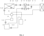
FIG. 1 is a schematic diagram of a first structure of an air conditioning system provided in the embodiments of this disclosure; -
FIG. 2 is a schematic diagram of a second structure of an air conditioning system provided in the embodiments of this disclosure; -
FIG. 3 is a schematic diagram of a first process of a method for detecting a refrigerant state provided in the embodiments of this disclosure; -
FIG. 4 is a schematic diagram of a second process of a method for detecting a refrigerant state provided in the embodiments of this disclosure; -
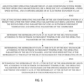
FIG. 5 is a schematic diagram of a third process of a method for detecting a refrigerant state provided in the embodiments of this disclosure; -
FIG. 6 is a schematic diagram of a fourth process of a method for detecting a refrigerant state provided in the embodiments of this disclosure; -
FIG. 7 is a schematic diagram of a fifth process of a method for detecting a refrigerant state provided in the embodiments of this disclosure; -
FIG. 8 is a schematic diagram of a sixth process of a method for detecting a refrigerant state provided in the embodiments of this disclosure; -
FIG. 9 is a schematic diagram of a seventh process of a method for detecting a refrigerant state provided in the embodiments of this disclosure; -
FIG. 10 is a schematic diagram of an eighth process of a method for detecting a refrigerant state provided in the embodiments of this disclosure; -
FIG. 11 is a schematic diagram of a structure of an apparatus for detecting a refrigerant state provided in the embodiments of this disclosure; -
FIG. 12 is a schematic diagram of a third structure of an air conditioning system provided in the embodiments of this disclosure. - In the following descriptions, for purposes of explanation instead of limitation, specific system architectures, technical details, and the like are set forth in order to provide a thorough understanding of the embodiments of the present disclosure. However, it will be apparent to those skilled in the art that the present disclosure may be implemented in other embodiments without these specific details. In other instances, detailed descriptions of well-known systems, apparatuses, circuits, and methods are omitted so as not to obscure the description of the present disclosure with unnecessary details.
- It will be understood that the terms "comprises" when used in the description of this disclosure and the appended claims, specifies the presence of stated features, integers, steps, operations, elements, and/or components, but does not preclude the presence or addition of one or more other features, integers, steps, operations, elements, components, and/or groups thereof.
- It will also be understood that the term "and/or" as used in the description of the disclosure and the appended claims refers to and encompasses any and all possible combinations of one or more of the associated listed items.
- As used herein, the term "if" may be construed to mean "when" or "upon" or "in response to determining" or "in response to detecting," depending on the context. Similarly, the phrase "if it is determined" or "if [a stated condition or event] is detected" may be construed to mean "upon determining" or "in response to determining" or "upon detecting [the stated condition or event]" or "in response to detecting [the stated condition or event]," depending on the context.
- In addition, in the descriptions of this disclosure and the appended claims, the terms "first", "second", "third", and the like are merely intended for a purpose of differentiated description, but shall not be understood as an indication or an implication of relative importance.
- The referenced "one embodiment" or "some embodiments" throughout the description of this disclosure means that one or more embodiments of the present disclosure include particular features, structures, or characteristics described in combination with the embodiment(s). Thus, the statements "in one embodiment", "in some embodiments", "in other embodiments", "in further embodiments" and the like appearing at different places in this description are not necessarily referring to the same embodiment(s), but rather mean "one or more but not all embodiments" unless otherwise specifically emphasized. The terms "including", "comprising", "having" and variations thereof mean "including, but not limited to", unless otherwise specifically emphasized.
- The embodiments of this disclosure provide a method for detecting a refrigerant state, which may be executed by a processor of an air conditioning system when running a corresponding computer program. The air conditioning system may be a stand-alone air conditioning system, or may be a multi-unit air conditioning system. The stand-alone air conditioning system and the multi-unit air conditioning system may be cooling-only systems for cooling only.
- In practice, an air conditioning system may include, but is not limited to, a memory, a processor, and a compressor, a heat exchanger, an electronic expansion valve, a pressure sensor, a temperature sensor, etc. which are connected to the processor, and may further include an oil separator, a four-way valve, a gas-liquid separator, an economizer, an evaporator, and pipelines connecting the components, and the like.
- The air conditioning system described in the embodiments of this disclosure does not constitute a limitation on the air conditioning system, and the air conditioning system may include more or fewer components, or some components, or different component arrangements.
- As shown in
FIG. 1 , a schematic diagram of a structural of an air conditioning system that does not include an economizer is shown as an example, in which the air conditioning system includes acompressor 10, anoil separator 20, a four-way valve 30, aheat exchanger 40, a gas-liquid separator 50, and anevaporator 60; - In which the
compressor 10 and theoil separator 20 are connected through an exhaust pipe therebetween, which is provided with an exhaust pressure sensor 11 and an exhaust temperature sensor 12; thecompressor 10 and the gas-liquid separator 50 are connected through a first return pipe therebetween, which is provided with a return air pressure sensor 13 and a return air temperature sensor 14; - The
oil separator 20 and the four-way valve 30 are connected through a high-pressure air pipe; - The four-
way valve 30 and theheat exchanger 40 are connected through a condenser pipe therebetween, which is provided with a heat exchanger inlet pressure sensor 31 and a heat exchanger inlet temperature sensor 32; the four-way valve 30 and the gas-liquid separator 50 are connected through a second return pipe therebetween, and the four-way valve 30 and theevaporator 60 are connected through a low-pressure air pipe therebetween; - The
heat exchanger 40 and theevaporator 60 are connected through a high-pressure liquid pipe therebetween, which is provided with a heat exchanger outlet pressure sensor 41, a heat exchanger outlet temperature sensor 42, a firstelectronic expansion valve 43, a high-pressure liquid pipe outlet pressure sensor 44 and a high-pressure liquid pipe outlet temperature sensor 45; theheat exchanger 40 is provided with an outdoorenvironment temperature sensor 46. - As shown in
FIG. 2 , a schematic diagram of a structural of an air conditioning system that includes an economizer is shown as an example, in which the air conditioning system further includes an economizer 70 in addition to those shown inFIG. 1 . An inlet of the economizer 70 is connected to the high-pressure liquid pipe 41 through an input pipe, which is provided with a secondelectronic expansion valve 71 and an economizerinlet temperature sensor 72. An outlet of the economizer 70 is connected to thecompressor 10 through an output pipe, which is provided with an economizer outlet temperature sensor 73. - As shown in
FIG. 3 , the method for detecting a refrigerant state for an air conditioning system provided in the embodiments of this disclosure includes the following steps S301 to S303:
At step S301, adjust first operating parameter of the air conditioning system, where the first operating parameter include a frequency of the compressor, a wind speed setting, and an opening degree of the electronic expansion valve. - In practice, the refrigerant state detection may be immediately and automatically performed after the air conditioning system is powered on, or may be performed automatically at any time when a user needs to after the air conditioning system is powered on. For example, the air conditioning system may be powered on when receiving a starting instruction sent by the user and adjust the first operating parameter of the air conditioning system to specified values; and may also adjust the first operating parameter of the air conditioning system to the specified values when receiving the refrigerant state detection instruction sent by the user after the air conditioning system is power on. The first operating parameter includes the frequency of the compressor of the outdoor unit of the air conditioning system, the wind speed setting of the outdoor unit, and the opening degree of the electronic expansion valve of the outdoor unit. In case where the air conditioning system does not include an economizer, the electronic expansion valve may be the electronic expansion valve of the outdoor unit, for example, the first
electronic expansion valve 43 shown inFIG. 1 ; in case where the air conditioning system includes an economizer, the electronic expansion valves may include both the electronic expansion valve of the outdoor unit and an electronic expansion valve of the economizer, for example, the firstelectronic expansion valve 43 and the secondelectronic expansion valve 71 shown inFIG. 2 . - At step S302, collect a second operating parameter of the air conditioning system after the adjustment of the first operating parameter has been completed for a preset duration, where the second operating parameter includes an outdoor environment temperature and an operating parameter of the compressor.
- At step S303, determine a refrigerant state of the air conditioning system according to the second operating parameter.
- In practice, the second operating parameter of the air conditioning system may be collected after the adjustment of the first operating parameter has been completed for a preset duration to enable the air conditioning system to stably operate in the refrigerant state detection mode, and the refrigerant state of the air conditioning system may be determined according to the second operating parameter. The preset duration may be customized by the user according to actual needs or use a value from the factory default settings, as long as the air conditioning system may stably operate after entering the refrigerant state detection mode for the preset duration.
- In practice, the outdoor environment temperature is the temperature of the outdoor environment where the outdoor unit is located, and may be detected by a temperature sensor positioned outdoors, for example, the outdoor environment temperature sensor 47 shown in
FIG. 1 orFIG. 2 . The operating parameter of the compressor may include, but are not limited to, the frequency of the compressor, an exhaust pressure, a return air pressure, a return air temperature, an exhaust temperature, and the like. The exhaust pressure, the return air pressure, the return air temperature, and the exhaust temperature of the compressor may be detected by respective pressure sensors and temperature sensors, such as the exhaust pressure sensor 12, the return air pressure sensor 15, the return air temperature sensor 16, and the exhaust temperature sensor 13 shown inFIG. 1 orFIG. 2 . In case where the air conditioning system does not include an economizer, the second operating parameter may further include a wind speed setting of the outdoor unit, an opening degree of the first electronic expansion valve, etc. In case where the air conditioning system includes an economizer, the second operating parameter may further include a wind speed setting of the outdoor unit, an economizer inlet temperature and an economizer outlet temperature, etc. The economizer inlet and outlet temperatures may be detected by a respective temperature sensor, for example, the economizerinlet temperature sensor 72 and economizer outlet temperature sensor 73 shown inFIG. 2 . - As shown in
FIG. 4 , in one embodiment, step S301 includes the following steps S401 and S402: - At step S401, enter the refrigerant state detection mode in response to receiving a power-on instruction or a refrigerant state detection instruction;
- At step S402, adjust the frequency of the compressor to a preset frequency, adjust the wind speed setting of the air conditioner outdoor unit to a preset wind speed setting, and adjust the opening degree of the electronic expansion valve of the air conditioner outdoor unit to a preset opening degree in the refrigerant state detection mode.
- In practice, the user may input the power-on instruction or the refrigerant state detection instruction through a human-computer interaction device of the air conditioning system according to actual needs, or send the power-on instruction or the refrigerant state detection instruction to the air conditioning system through a terminal device in communication connection with the air conditioning system, so as to control the air conditioning system to enter the refrigerant state detection mode. The human-computer interaction device of the air conditioning system may include at least one of a physical button, a touch sensor, a gesture recognition sensor and a speech recognition unit, so that the user may input the instruction with a corresponding touch control, gesture control, or a speech control.
- In practice, the physical button and the touch sensor may be provided at any position of the air conditioning system, for example, at a control panel. The touch control of the physical button may be specifically by pressing or toggling. The touch control of the touch sensor may be specifically by pressing or touching, etc.
- In practice, the gesture recognition sensor may be provided at any position of the air conditioning system, for example, outside the housing near the vent. The gesture for controlling the air conditioning system may be customized by the user according to actual needs or use a gesture from the factory default settings.
- In practice, the speech recognition unit may include a microphone and a speech recognition chip, or may only include a microphone and a processor of the air conditioning system may implement speech recognition. The speech used to control the air conditioner may be customized by the user according to actual needs or may use a speech from the factory default settings.
- In practice, the terminal device may be a mobile phone, a smart wristband, a tablet computer, a notebook computer, a netbook, a personal digital assistant (PDA), etc. which have a wireless communication function and may be in wireless communication connection with the air conditioning system. The embodiments of the disclosure provide no limitation on the specific type of the terminal device. The user may control, by means of any human-computer interaction supported by the terminal device, the terminal device to send an instruction to the air conditioning system. The human-computer interaction supported by the terminal device may be the same as the air conditioning system, and details are not described herein again.
- In practice, the preset frequency, the preset wind speed setting, and the preset opening degree may be customized by the user according to actual needs or use those from the factory default settings, as long as the air conditioning system may gradually tend to be stable after entering the refrigerant state detection mode.
- As shown in
FIG. 5 , in one embodiment, step S303 includes:
At step S501, determine the refrigerant state at an inlet of the heat exchanger according to the outdoor environment temperature and the operating parameter of the compressor. - In practice, the refrigerant state at the inlet of the heat exchanger may be determined according to the outdoor environment temperature and the operating parameter of the compressor. Specifically, it is possible to calculate the heat exchanger inlet temperature and a saturation temperature corresponding to the heat exchanger inlet pressure according to the outdoor environment temperature and the frequency, the exhaust pressure, the return air pressure, the return air temperature and the exhaust temperature of the compressor, and then determine the refrigerant state at the inlet of the heat exchanger according to the heat exchanger inlet temperature and the saturation temperature corresponding to the heat exchanger inlet pressure.
- As shown in
FIG. 6 , in one embodiment, step S501 includes the following steps S601 to S603: - At step S601: obtain the heat exchanger inlet temperature and the saturation temperature corresponding to the heat exchanger inlet pressure according to the outdoor environment temperature and the operating parameter of the compressor;
- At step S602: if the heat exchanger inlet temperature is greater than the sum of the saturation temperature corresponding to the heat exchanger inlet pressure and a first preset temperature threshold, then determine that the refrigerant at the inlet of the heat exchanger is in an overheating state;
- At step S603, if the heat exchanger inlet temperature is less than or equal to the sum of the saturation temperature corresponding to the heat exchanger inlet pressure and the first preset temperature threshold, then determine that the refrigerant at the inlet of the heat exchanger is in a non-overheating state, and adjust the first operating parameter.
- In practice, after the heat exchanger inlet temperature and the saturation temperature corresponding to the heat exchanger inlet pressure have been calculated, it is possible to compare the heat exchanger inlet temperature with the sum of the saturation temperature corresponding to the heat exchanger inlet pressure and the first preset temperature thresholds, and then determine the refrigerant state at the inlet of the heat exchanger according to the comparison result. If the refrigerant at the inlet of the heat exchanger is in the overheating state, then proceed to the next step, to continue to detect the refrigerant state at the outlet of the heat exchanger. If the refrigerant at the inlet of the heat exchanger is in the non-overheating state, then return to step S301, to continue to adjust the first operating parameter. The first preset temperature threshold may be customized by the user according to actual needs or use a value from the factory default settings, for example, any value between 1°C and 3°C.
- In one embodiment, step S601 includes the following steps:
- obtaining a refrigerant flow rate according to the frequency, the exhaust pressure, the return air pressure and the return air temperature of the compressor;
- obtaining a pressure drop of an exhaust pipeline of the compressor according to the exhaust temperature and the exhaust pressure of the compressor and the refrigerant flow rate;
- obtaining a heat leakage of the exhaust pipeline of the compressor according to the outdoor environment temperature, the exhaust temperature of the compressor, and the refrigerant flow rate;
- obtaining the heat exchanger inlet pressure according to the exhaust pressure of the compressor and the pressure drop of the exhaust pipeline;
- obtaining the heat exchanger inlet temperature according to the exhaust temperature of the compressor, the refrigerant flow rate, and the heat leakage of the exhaust pipeline;
- obtaining the saturation temperature corresponding to the heat exchanger inlet pressure according to the heat exchanger inlet pressure.
- In practice, firstly a saturation temperature corresponding to the exhaust pressure of the compressor, that is, the condensation temperature, is calculated according to the exhaust pressure of the compressor, and a saturation temperature corresponding to the return air pressure of the compressor, that is, the evaporation temperature, is calculated according to the return air pressure of the compressor; and then the refrigerant flow rate is calculated according to the 10 coefficients of the compressor flow related to the frequency, the exhaust pressure, the return air pressure and the return air temperature of the compressor, the condensation temperature and the evaporation temperature.
- In an embodiment, the calculation formulas of the refrigerant flow rate are as follows:


- The calculation formula of the pressure drop of the exhaust pipeline of the compressor is as follows:

- The calculation formula of the heat leakage of the exhaust pipeline of the compressor is as follows:

- The calculation formula of the heat exchanger inlet pressure is as follows:

- The calculation formula of the heat exchanger inlet temperature is as follows:

- The calculation formula of the saturation temperature corresponding to the heat exchanger inlet pressure is as follows:

- where m is the refrigerant flow rate, k1~k10 are the ten coefficients related to the frequency, the exhaust pressure pd, the return air pressure ps and the return air temperature Ts of the compressor, Te is the saturation temperature corresponding to the return air pressure of the compressor, Tc is the saturation temperature corresponding to the exhaust pressure pd of the compressor, and B1~B2 and b1∼b3 are refrigerant physical parameters related to the refrigerant type;
- dp1 is the pressure drop of the exhaust pipeline of the compressor, f1(m, Td, pd) is a function related to the exhaust temperature Td and the exhaust pressure pd of the compressor and the refrigerant flow rate m, and A1~A2 are parameters related to the structure of the exhaust pipeline;
- Q1 is the heat leakage of the exhaust pipeline of the compressor, and f2(m, Td, T0) is a function related to the outdoor environment temperature T0, the exhaust temperature Td of the compressor, and the refrigerant flow rate m;
- p1 is the heat exchanger inlet pressure;
- T1 is the heat exchanger inlet temperature;
- T1s is the saturation temperature corresponding to the heat exchanger inlet pressure;
- * is a multiplication operator, ^ is a exponentiation operator, / is an division operator, In () is a logarithmic function.
- As shown in
FIG. 5 , in one embodiment, step S303 further includes:
Step S502, determining the refrigerant state at the outlet of the heat exchanger according to the outdoor environment temperature, the operating parameter of the heat exchanger, and the wind speed setting, if the refrigerant at the inlet of the heat exchanger is in an overheating state. - In practice, if the refrigerant at the inlet of the heat exchanger is in the overheating state, then it is possible to further determine the refrigerant state at the outlet of the heat exchanger according to the outdoor environment temperature, the operating parameter of the heat exchanger, and the wind speed setting. The operating parameter of the heat exchanger may include, but are not limited to, an inlet pressure, an outlet pressure, an inlet temperature and an outlet temperature of the heat exchanger, and the like. The inlet pressure, the outlet pressure, the inlet temperature and the outlet temperature of the heat exchanger may be detected by respective pressure sensors and temperature sensors, such as the heat exchanger inlet pressure sensor 31, the heat exchanger outlet pressure sensor 41, the heat exchanger inlet temperature sensor 32, and the heat exchanger outlet temperature sensor 42 shown in
FIG. 1 orFIG. 2 . Specifically, it is possible to calculate the heat exchanger outlet temperature and a saturation temperature corresponding to the heat exchanger outlet pressure according to the outdoor environment temperature, the refrigerant flow rate, the heat exchanger inlet pressure and inlet temperature, the saturation temperature corresponding to the heat exchanger inlet pressure and the wind speed setting, and then determine the refrigerant state at the outlet of the heat exchanger according to the heat exchanger outlet temperature and the saturation temperature corresponding to the heat exchanger outlet pressure. - As shown in
FIG. 7 , in one embodiment, step S502 includes the following steps S701 to S703: - At step S701, obtain the heat exchanger outlet temperature and the saturation temperature corresponding to the heat exchanger outlet pressure according to the outdoor environment temperature, the refrigerant flow rate, the operating parameter of the heat exchanger and the wind speed setting;
- At step S702, if the heat exchanger outlet temperature is less than a difference between the saturation temperature corresponding to the heat exchanger outlet pressure and the first preset temperature threshold, then determine that the refrigerant at the outlet of the heat exchanger is in a supercooling state.
- At step S703, if the heat exchanger outlet temperature is greater than or equal to the difference between the saturation temperature corresponding to the heat exchanger outlet pressure and the first preset temperature threshold, then determine that the refrigerant at the outlet of the heat exchanger is in a non-supercooling state, and adjust the first operating parameter of the air conditioning system.
- In practice, after the heat exchanger outlet temperature and the saturation temperature corresponding to the heat exchanger outlet pressure have been calculated, it is possible to compare the heat exchanger outlet temperature with the difference between the saturation temperature corresponding to the heat exchanger outlet pressure and the first preset temperature threshold, then determine the refrigerant state at the outlet of the heat exchanger according to the comparison result. If the refrigerant at the outlet of the heat exchanger is in the supercooling state, then proceed to the next step, to continue to detect the refrigerant state at the outlet of the high-pressure liquid pipe. If the refrigerant at the inlet of the heat exchanger is in the non-supercooling state, then return to step S301, to continue to adjust the first operating parameter.
- In one embodiment, step S701 includes the following steps:
- obtaining a refrigerant pressure drop of the heat exchanger according to the wind speed setting and the refrigerant flow rate;
- obtaining a heat exchange of the heat exchanger according to the outdoor environment temperature, the wind speed setting, the refrigerant flow rate, and the heat exchanger inlet pressure and the inlet temperature;
- obtaining the heat exchanger outlet pressure according to the heat exchanger inlet pressure and the refrigerant pressure drop of the heat exchanger;
- obtaining the heat exchanger outlet temperature according to the refrigerant flow rate, the heat exchange inlet temperature, the heat exchange of the heat exchange and the saturation temperature corresponding to the heat exchanger inlet pressure;
- obtaining the saturation temperature corresponding to the heat exchanger outlet pressure according to the heat exchanger outlet pressure.
- In one embodiment, the calculation formula of the refrigerant pressure drop of the heat exchanger is as follows:

- The calculation formula of the heat exchange of the heat exchanger is as follows:

- The calculation formula of the heat exchanger outlet pressure is as follows:

- The calculation formula of the heat exchanger outlet temperature is as follows:

- The calculation formula of the saturation temperature corresponding to the heat exchanger outlet pressure is as follows:

- where dp2 is the refrigerant pressure drop of the compressor, f3(m, Fs) is a function related to the refrigerant flow rate m and the wind speed setting Fs, A3~A6 are parameters related to the structure of the heat exchanger, and c0~c3 are parameters related to the characteristics of the fan of the outdoor unit;
- Q2 is the heat exchange of the heat exchanger, f4(m, T1s, Fs, T0) is a function related to the refrigerant flow rate m, the saturation temperature T1s corresponding to the heat exchanger inlet pressure, the wind speed setting Fs, and the outdoor environment temperature T0;
- p2 is the heat exchanger outlet pressure;
- T2 is the heat exchanger outlet temperature;
- T2s is the saturation temperature corresponding to the heat exchanger outlet pressure.
- As shown in
FIG. 5 , in one embodiment, step S303 further includes:
step S503, if the refrigerant at the outlet of the heat exchanger is in the supercooling state, then determining the refrigerant state at the outlet of the high-pressure liquid pipe according to the outdoor environment temperature, the operating parameter of the heat exchanger and the opening degree of the first electronic expansion valve. - In practice, if the refrigerant at the outlet of the heat exchanger is in the supercooling state, then it is possible to further determine the refrigerant state at the outlet of the high-pressure liquid pipe according to the outdoor environment temperature, the operating parameter of the heat exchanger and the opening degree of the first electronic expansion valve. Specifically, it is possible to calculate the high-pressure liquid pipe outlet temperature and a saturation temperature corresponding to the high-pressure liquid pipe outlet pressure according to the outdoor environment temperature, the refrigerant flow rate, the heat exchanger outlet pressure and outlet temperature, the saturation temperature corresponding to the heat exchanger outlet pressure and the opening degree of the first electronic expansion valve, and then determine the refrigerant state at the outlet of the high-pressure liquid pipe according to the high-pressure liquid pipe outlet temperature and the saturation temperature corresponding to the high-pressure liquid pipe outlet pressure.
- As shown in
FIG. 8 , in one embodiment, no matter whether the air conditioning system includes an economizer or not, step S503 includes the following steps S801 and S802: - At S801, obtain the high-pressure liquid pipe outlet temperature and the saturation temperature corresponding to the high-pressure liquid pipe outlet pressure according to the outdoor environment temperature, the refrigerant flow rate, the operating parameter of the heat exchanger and the opening degree of the first electronic expansion valve;
- At S802, if the high-pressure liquid pipe outlet temperature is less than a difference between the saturation temperature corresponding to the high-pressure liquid pipe outlet pressure and the first preset temperature threshold, then determine that the refrigerant at the outlet of the high-pressure liquid pipe is in a supercooling state.
- In practice, after the high-pressure liquid pipe outlet temperature and the saturation temperature corresponding to the high-pressure liquid pipe outlet pressure have been calculated, it is possible to compare the high-pressure liquid pipe outlet temperature with the difference between the saturation temperature corresponding to the high-pressure liquid pipe outlet pressure and the first preset temperature threshold, and then determine the refrigerant state at the outlet of the high-pressure liquid pipe according to the comparison result. For an air conditioning system without an economizer, it is possible to determine that the refrigerant at the outlet of the high-pressure liquid pipe is in a supercooling state or in a non-supercooling state according to the high-pressure liquid pipe outlet temperature and the saturation temperature corresponding to the high-pressure liquid pipe outlet pressure. For an air conditioning system with an economizer, it is only possible to determine the supercooling state of the refrigerant at the outlet of the high-pressure liquid pipe according to the high-pressure liquid pipe outlet temperature and the saturation temperature corresponding to the high-pressure liquid pipe outlet pressure, and the non-supercooling state should be determined according to an economizer inlet temperature and an economizer outlet temperature.
- In one embodiment, step S801 includes the following steps:
- obtaining a refrigerant pressure drop of the high-pressure liquid pipe according to the refrigerant flow rate, the heat exchanger outlet temperature and the opening degree of the first electronic expansion valve;
- obtaining a heat leakage of the high-pressure liquid pipe according to the outdoor environment temperature, the refrigerant flow rate, and the heat exchanger outlet temperature;
- obtaining the high-pressure liquid pipe outlet pressure according to the heat exchanger outlet pressure and the refrigerant pressure drop of the high-pressure liquid pipe;
- obtaining the high-pressure liquid pipe outlet temperature according to the refrigerant flow rate, the heat exchanger outlet temperature, the saturation temperature corresponding to the heat exchanger outlet pressure and the heat leakage of the high-pressure liquid pipe;
- obtaining the saturation temperature corresponding to the high-pressure liquid pipe outlet pressure according to the high-pressure liquid pipe outlet pressure.
- In one embodiment, the calculation formula of the refrigerant pressure drop of the high-pressure liquid pipe is as follows:

- The calculation formula of the heat leakage of the high-pressure liquid pipe is as follows:

- The calculation formula of the high-pressure liquid pipe outlet pressure is as follows:

- The calculation formula of the high-pressure liquid pipe outlet temperature is as follows:

- The calculation formula of the saturation temperature corresponding to the high-pressure liquid pipe outlet pressure is as follows:

- where dp3 is the refrigerant pressure drop of the high-pressure liquid pipe, f5(m, T2, EXV) is a function related to the refrigerant flow rate m, the heat exchanger outlet temperature T2 and the opening degree EXV of the first electronic expansion valve, A7~A8 are parameters related to the structure of the high-pressure liquid pipe, D0∼D1 are parameters related to the characteristics of the first electronic expansion valve, and B3 is a refrigerant physical parameter related to the refrigerant type;
- Q3 is the heat leakage of the high-pressure liquid pipe, and f6(m, T2, T0) is a function related to the refrigerant flow rate m, the heat exchanger outlet temperature T2 and the outdoor environment temperature T0;
- p3 is the high-pressure liquid pipe outlet pressure;
- T3 is the high-pressure liquid pipe outlet temperature;
- T3s is the saturation temperature corresponding to the high-pressure liquid pipe outlet pressure.
- The method for detecting a refrigerant state provided in the embodiments corresponding to
FIG. 8 may be applicable to refrigerant state detection for any air conditioning system. - As shown in
FIG. 9 , in one embodiment, the air conditioning system does not include an economizer, and step S503 further includes the following step S803: - At step S803, if the high-pressure liquid pipe outlet temperature is greater than or equal to the difference between the saturation temperature corresponding to the high-pressure liquid pipe outlet pressure and the first preset temperature threshold, then determine that the refrigerant at the outlet of the high-pressure liquid pipe is in a non-supercooling state.
- The method for detecting a refrigerant state provided in the embodiments corresponding to
FIG. 9 may be applicable to refrigerant state detection for an air conditioning system that does not include an economizer. - As shown in
FIG. 10 , in one embodiment, the air conditioning system includes an economizer, and step S303 further includes the following step S504:
At step S504, if the refrigerant at the outlet of the heat exchanger is in the supercooling state, then determine the refrigerant state at the outlet of the high-pressure liquid pipe of the air conditioner outdoor unit according to the economizer inlet temperature and the economizer outlet temperature. - In practice, if the refrigerant at the outlet of the heat exchanger is in the supercooling state, then it is possible to further determine the refrigerant state at the outlet of the high-pressure liquid pipe according to the economizer inlet temperature and the economizer outlet temperature.
- In one embodiment, step S504 includes the following steps:
- if a difference between the economizer outlet temperature and the economizer inlet temperature is less than a second preset temperature threshold, then determining that the refrigerant at the outlet of the high-pressure liquid pipe of the air conditioner outdoor unit is in a supercooling state;
- if the difference between the economizer outlet temperature and the economizer inlet temperature is greater than or equal to the second preset temperature threshold, then determining that the refrigerant at the outlet of the high-pressure liquid pipe of the air conditioner outdoor unit is in a non-supercooling state.
- In practice, after the economizer outlet temperature and the economizer inlet temperature have been collected, it is possible to compare the difference between the economizer outlet temperature and the economizer inlet temperature with the second preset temperature threshold, and then determine the refrigerant state at the outlet of the high-pressure liquid pipe according to the comparison result. The second preset temperature threshold may be customized by the user according to actual needs or use a value from the factory default settings, for example, any value between 1°C and 5°C.
- The method for detecting a refrigerant state provided in the embodiments corresponding to
FIG. 10 may be applicable to refrigerant state detection for an air conditioning system including an economizer. - The embodiments of this disclosure adjusts the frequency of the compressor, the wind speed setting and the opening degree of the electronic expansion valve of the air conditioning system, and collects the outdoor environment temperature and the operating parameter of the air conditioning system such as the frequency, the exhaust pressure, the return air pressure, the return air temperature and the exhaust temperature of the compressor, and the wind speed setting and the opening degree of the first electronic expansion valve of the outdoor unit, after the system operates stably, thereby the embodiments of the disclosure may accurately obtain the refrigerant state of the air conditioning system according to the operating parameter of the air conditioning system, and improve the safety and reliability of the air conditioning system during use.
- It should be understood that the reference number of the steps in the above-mentioned embodiments does not define the execution sequence of each process, which should be determined by the function and internal logic thereof, and should not constitute any limitation on the implementation process of the embodiments of this disclosure.
- The embodiments of the present disclosure further provides a refrigerant state detection apparatus applicable to an air conditioning system, and the refrigerant state detection device is used for executing the method steps in the above method for detecting a refrigerant state embodiments. The refrigerant state detection apparatus may be a virtual appliance in the air conditioning system operated by a processor of the air conditioning system, or may be the air conditioning system itself.
- As shown in
FIG. 11 , the refrigerantstate detection apparatus 100 provided in the embodiments of this disclosure includes: - a
parameter adjustment unit 101 for adjusting first operating parameter of the air conditioning system, where the first operating parameter includes a frequency of a compressor, a wind speed setting, and an opening degree of an electronic expansion valve of an air conditioner outdoor unit; - a
parameter collection unit 102 for collecting second operating parameter of the air conditioning system after the adjustment of the first operating parameter has been completed for a preset duration, where the second operating parameter includes an outdoor environment temperature and an operating parameter of the compressor; - a refrigerant
state detection unit 103 for determining a refrigerant state of the air conditioning system according to the second operating parameter. - In one embodiment, the parameter adjustment unit includes:
- an instruction receiving subunit for entering a refrigerant state detection mode in respond to receiving of a power-on instruction or a refrigerant state detection instruction;
- a parameter adjustment subunit for adjusting, in the refrigerant state detection mode, the frequency of the compressor to be a preset frequency, adjusting the wind speed setting of the air conditioner outdoor unit to be a preset wind speed setting, and adjust the opening degree of the electronic expansion valve of the air conditioner outdoor unit to be a preset opening degree.
- In one embodiment, the refrigerant state detection unit includes:
- a refrigerant state detection subunit for determining a refrigerant state at an inlet of a heat exchanger according to the outdoor environment temperature and the operating parameter of the compressor;
- a first determining subunit for determining a refrigerant state at an outlet of the heat exchanger according to the outdoor environment temperature, the operating parameter of the heat exchanger and the wind speed setting, if the refrigerant at the inlet of the heat exchanger is in an overheating state;
- a second determining subunit for determining a refrigerant state at an outlet of a high-pressure liquid pipe according to the outdoor environment temperature, the operating parameter of the heat exchanger and the opening degree of the electronic expansion valve, if the refrigerant at the outlet of the heat exchanger is in a supercooling state; or a third determining subunit for determining the refrigerant state at the outlet of the high-pressure liquid pipe of the air conditioner outdoor unit according to the economizer inlet temperature and the economizer outlet temperature if the refrigerant at the outlet of the heat exchanger is in the supercooling state.
- In practice, each unit in the refrigerant state detection apparatus may be a software program unit, or may be implemented by means of different logic circuits integrated in the processor, or may be implemented by means of a plurality of distributed processors. A temperature obtaining unit may include a temperature sensor.
- As shown in
FIG. 12 , the embodiments of this disclosure further provide anair conditioning system 200, which includes: at least one processor 201 (only one processor is shown inFIG. 12 ), amemory 202, and acomputer program 203 stored in thememory 202 and executable on the at least oneprocessor 201, and further includes acompressor 204, aheat exchanger 205, anelectronic expansion valve 206, apressure sensor 207 and atemperature sensor 208 connected to the at least oneprocessor 201. When executing thecomputer program 203, theprocessor 201 implements the steps in each of the above-mentioned embodiments of the method for detecting a refrigerant state. - In practice, the air conditioning system may include, but is not limited to, a processor, a memory, a compressor, a heat exchanger, an electronic expansion valve, a pressure sensor, and a temperature sensor, and may further include an oil separator, a four-way valve, a gas-liquid separator, an economizer, an evaporator, pipelines connecting the components, and the like. Those skilled in the art may understand that
FIG. 12 is merely an example of the air conditioning system, and does not constitute a limitation on the air conditioning system, which may more or fewer components than those shown in the figure, or a combination of some components or different components. For example, it may further include an input/output device, a network access device, and the like. - In practice, the processor may be a Central Processing Unit (CPU), or be other general purpose processor, a Digital Signal Processor (DSP), an Application Specific Integrated Circuit (ASIC), a Field-Programmable Gate Array (FPGA), or be other programmable logic device, discrete gate or transistor logic device, discrete hardware component, and etc. The general purpose processor may be a microprocessor, or the processor may also be any conventional processor.
- In practice, the storage may be an internal storage unit of the air conditioning system in some embodiments, for example, a hard disk or a memory of the air conditioning system. The air conditioning system may also be an external storage device of the air conditioning system in some other embodiments, for example, a plug-in hard disk, a Smart Media Card (SMC), a Secure Digital (SD) card, a Flash Card, and the like, which is provided on the air conditioning system. Further, the storage may include both the internal storage unit and the external storage device, of the air conditioning system. The storage is configured to store an operating system, application programs, a Boot Loader, data and other programs such as a program code of a computer program. The storage may also be used to temporarily store data that has been or will be output.
- It should be noted that content such as the execution processes and the information interactions between the devices/units described above are of the same concept as the method embodiments of the present disclosure, therefore reference may be made to the method embodiments for the specific functions and technical effects brought about. The details are not described herein again.
- Those skilled in the art may clearly understand that, for the convenience and simplicity of description, the division of the above-mentioned functional units or modules is merely an example for illustration. In actual applications, the above-mentioned functions may be allocated to be performed by different functional units according to requirements, that is, the internal structure of the device may be divided into different functional units to complete all or part of the above-mentioned functions. The functional units in the embodiments may be integrated in one processing unit, or each unit may exist alone physically, or two or more units may be integrated in one unit. The above-mentioned integrated unit may be implemented in the form of hardware or in the form of software functional unit. In addition, the specific name of each functional unit is merely for the convenience of distinguishing each other and are not intended to limit the scope of protection of the present disclosure. For the specific operation processes of the units or modules in the above-mentioned system, reference may be made to the corresponding processes in the above-mentioned method embodiments. And the details will not be repeated here.
- The embodiments of the present disclosure further provide a computer-readable storage medium storing a computer program, which, when executed by a processor, implements the steps in each of the foregoing embodiments of the method for detecting a refrigerant state.
- The embodiments of the present disclosure provide a computer program product, which, when running on an air conditioning system, enables the air conditioning system to implement the steps in each of the foregoing embodiments of the method for detecting a refrigerant state.
- When the integrated unit is implemented in the form of a software functional unit and is sold or used as an independent product, the integrated unit may be stored in a computer-readable storage medium. Based on this understanding, all or part of the processes of the method for implementing the above-mentioned embodiments of the present disclosure may also be implemented by instructing relevant hardware through a computer program. The computer program may be stored in a computer-readable storage medium, which may implement the steps of each of the above-mentioned method embodiments when executed by a processor. Wherein, the computer program includes computer program codes which may be in the form of source codes, object codes, executable files, or certain intermediate and the like. The computer-readable medium may include at least any primitive or device capable of carrying the computer program codes into the air conditioning system, a recording medium, computer memory, a Read-Only Memory (ROM), a Random Access Memory (RAM), electric carrier signals, telecommunication signals and software distribution media. For example, a USB flash drive, a portable hard disk, a magnetic disk, or an optical disk, and the like.
- In the above embodiments, the description on each embodiment has its own emphasis, and for the part that are not described in detail or specified in some embodiments, one may refer to a related description on other embodiments.
- Those skilled in the art may understand that the exemplary units and algorithm steps described in combination with the embodiments disclosed herein can be implemented with electronic hardware, or a combination of computer software and electronic hardware. Whether the functions are performed by hardware or software depends on the specific application and designed constraint conditions of the technical solutions. Those skilled in the art may use different methods to implement the described functions for each specific application, but this should not be considered as beyond the scope of the present disclosure.
- It should be understood that the disclosed apparatus and method in the embodiments provided in this disclosure may be implemented in other ways. For example, the apparatus embodiments described above are only illustrative. For example, the division of the units is only a logic functional division, and other division is possible in practical implementation. For example, multiple units or components may be combined or integrated into another system, or some features may be omitted, or not implemented. In addition, the intercoupling or direct coupling or communication connection shown or discussed may be through some interfaces, and the indirect coupling or communication connection between devices or units may be in electrical, mechanical or in other forms.
- The unit described as a separate component may or may not be physically separated, and the part displayed as a unit may or may not be a physical unit, that is, it may be located in one place, or may also be distributed on multiple network units. Part or all of the units may be selected according to actual needs to achieve the purpose of the solutions of the embodiments.
- The above-mentioned embodiments are merely intended for describing but not for limiting the technical solutions of the present disclosure. Although the present disclosure is described in detail with reference to the above-mentioned embodiments, it should be understood by those skilled in the art that, the technical solutions in each of the above-mentioned embodiments may still be modified, or some of the technical features may be equivalently replaced, while these modifications or replacements do not make the essence of the corresponding technical solutions depart from the spirit and scope of the technical solutions of each of the embodiments of the present disclosure, and should be included within the scope of the present disclosure.
Claims (11)
- A method for detecting a refrigerant state, characterized in that the method comprises:adjusting a first operating parameter of an air conditioning system, wherein the first operating parameter comprises a frequency of a compressor, a wind speed setting, and an opening degree of an electronic expansion valve;collecting a second operating parameter of the air conditioning system after the adjustment of the first operating parameter has been completed for a preset duration, wherein the second operating parameter comprises an outdoor environment temperature and an operating parameter of the compressor; anddetermining a refrigerant state of the air conditioning system according to the second operating parameter.
- The method according to claim 1, wherein said determining a refrigerant state of the air conditioning system according to the second operating parameter comprises:
determining a refrigerant state at an inlet of a heat exchanger according to an outdoor environment temperature and the operating parameter of the compressor. - The method for detecting a refrigerant state according to claim 2, wherein said determining a refrigerant state at an inlet of a heat exchanger according to an outdoor environment temperature and the operating parameter of the compressor comprises:obtaining a heat exchanger inlet temperature and a saturation temperature corresponding to a heat exchanger inlet pressure according to the outdoor environment temperature and the operating parameter of the compressor;determining that the refrigerant at the inlet of the heat exchanger is in an overheating state in case the heat exchanger inlet temperature is greater than a sum of the saturation temperature corresponding to the heat exchanger inlet pressure and a first preset temperature threshold; and determining that the refrigerant at the inlet of the heat exchanger is in a non-overheating state and adjusting the first operating parameter in case the heat exchanger inlet temperature is less than or equal to the sum of the saturation temperature corresponding to the heat exchanger inlet pressure and the first preset temperature threshold.
- The method for detecting a refrigerant state according to claim 3, wherein said obtaining a heat exchanger inlet temperature and a saturation temperature corresponding to a heat exchanger inlet pressure according to the outdoor environment temperature and the operating parameter of the compressor comprises:obtaining a refrigerant flow rate according to the frequency, an exhaust pressure, a return air pressure and a return air temperature of the compressor;obtaining a pressure drop of an exhaust pipeline of the compressor according to an exhaust temperature and the exhaust pressure of the compressor and the refrigerant flow rate;obtaining a heat leakage of the exhaust pipeline of the compressor according to the outdoor environment temperature, the exhaust temperature of the compressor, and the refrigerant flow rate;obtaining the heat exchanger inlet pressure according to the exhaust pressure of the compressor and the pressure drop of the exhaust pipeline;obtaining the heat exchanger inlet temperature according to the exhaust temperature of the compressor, the refrigerant flow rate, and the heat leakage of the exhaust pipeline;obtaining the saturation temperature corresponding to the heat exchanger inlet pressure according to the heat exchanger inlet pressure.
- The method for detecting a refrigerant state according to claim 4, wherein the second operating parameter further comprises the wind speed setting;
said determining a refrigerant state of the air conditioning system according to the second operating parameter further comprises:
determining a refrigerant state at an outlet of the heat exchanger according to the outdoor environment temperature, the refrigerant flow rate, the operating parameter of the heat exchanger and the wind speed setting in case the refrigerant at the inlet of the heat exchanger is in an overheating state. - The method for detecting a refrigerant state according to claim 5, wherein said determining a refrigerant state at an outlet of the heat exchanger according to the outdoor environment temperature, the refrigerant flow rate, the operating parameter of the heat exchanger and the wind speed setting comprises:obtaining a heat exchanger outlet temperature and a saturation temperature corresponding to a heat exchanger outlet pressure according to the outdoor environment temperature, the refrigerant flow rate, the operating parameter of the heat exchanger and the wind speed setting;determining that the refrigerant at the outlet of the heat exchanger is in a supercooling state in case the heat exchanger outlet temperature is less than a difference between the saturation temperature corresponding to the heat exchanger outlet pressure and the first preset temperature threshold; and determining that the refrigerant at the outlet of the heat exchanger is in a non-supercooling state and adjusting the first operating parameter of the air conditioning system in case the heat exchanger outlet temperature is greater than or equal to the difference between the saturation temperature corresponding to the heat exchanger outlet pressure and the first preset temperature threshold.
- The method for detecting a refrigerant state according to claim 6, wherein said obtaining a heat exchanger outlet temperature and a saturation temperature corresponding to a heat exchanger outlet pressure according to the outdoor environment temperature, the refrigerant flow rate, the operating parameter of the heat exchanger and the wind speed setting comprises:obtaining a refrigerant pressure drop of the heat exchanger according to the wind speed setting and the refrigerant flow rate;obtaining a heat exchange of the heat exchanger according to the outdoor environment temperature, the wind speed setting, the refrigerant flow rate, the heat exchanger inlet pressure and the heat exchanger inlet temperature;obtaining the heat exchanger outlet pressure according to the heat exchanger inlet pressure and the refrigerant pressure drop of the heat exchanger;obtaining the heat exchanger outlet temperature according to the refrigerant flow rate, the heat exchange inlet temperature, the heat exchange of the heat exchange and the saturation temperature corresponding to the heat exchanger inlet pressure; andobtaining the saturation temperature corresponding to the heat exchanger outlet pressure according to the heat exchanger outlet pressure.
- The method for detecting a refrigerant state according to claim 7, wherein the second operating parameter further comprises an opening degree of a first electronic expansion valve;
said determining a refrigerant state of the air conditioning system according to the second operating parameter further comprises:
determining a refrigerant state at an outlet of a high-pressure liquid pipe according to the outdoor environment temperature, the operating parameter of the heat exchanger and the opening degree of the first electronic expansion valve in case the refrigerant at the outlet of the heat exchanger is in the supercooling state. - The method for detecting a refrigerant state according to claim 8, wherein said determining a refrigerant state at an outlet of a high-pressure liquid pipe according to the outdoor environment temperature, the operating parameter of the heat exchanger and the opening degree of the first electronic expansion valve comprises:Obtaining a high-pressure liquid pipe outlet temperature and a saturation temperature corresponding to a high-pressure liquid pipe outlet pressure according to the outdoor environment temperature, the refrigerant flow rate, the operating parameter of the heat exchanger and the opening degree of the first electronic expansion valve;Determining that the refrigerant at the outlet of the high-pressure liquid pipe is in the supercooling state in case the high-pressure liquid pipe outlet temperature is less than a difference between the saturation temperature corresponding to the high-pressure liquid pipe outlet pressure and the first preset temperature threshold; andDetermining that the refrigerant at the outlet of the high-pressure liquid pipe is in a non-supercooling state in case the high-pressure liquid pipe outlet temperature is greater than or equal to the difference between the saturation temperature corresponding to the high-pressure liquid pipe outlet pressure and the first preset temperature threshold.
- A apparatusfor detecting a refrigerant state, refrigerant state detection characterized in that the apparatus comprises:a parameter adjustment unit for adjusting a first operating parameter of an air conditioning system; wherein the first operating parameter comprises a frequency of a compressor, a wind speed setting, and an opening degree of an electronic expansion valve of an air conditioner outdoor unit;a parameter collection unit for collecting a second operating parameter of the air conditioning system after the adjustment of the first operating parameter has been completed for a preset duration; wherein the second operating parameter comprises an outdoor environment temperature and an operating parameter of the compressor;anda refrigerant state detection unit for determining a refrigerant state of the air conditioning system according to the second operating parameter.
- An air conditioning system, comprising a memory, a processor and a computer program stored in the memory and executable on the processor, characterized in that the processor implements steps of the method for detecting a refrigerant state according to any one of claims 1-9 when executing the computer program.
Applications Claiming Priority (2)
| Application Number | Priority Date | Filing Date | Title |
|---|---|---|---|
| CN202110055363.5A CN112856716B (en) | 2021-01-15 | 2021-01-15 | A kind of air conditioning system and its refrigerant state detection method and device |
| PCT/CN2021/116969 WO2022151747A1 (en) | 2021-01-15 | 2021-09-07 | Air conditioning system and refrigerant state inspection method and device thereof |
Publications (3)
| Publication Number | Publication Date |
|---|---|
| EP4261471A1 true EP4261471A1 (en) | 2023-10-18 |
| EP4261471A4 EP4261471A4 (en) | 2024-07-03 |
| EP4261471B1 EP4261471B1 (en) | 2025-12-31 |
Family
ID=76006779
Family Applications (1)
| Application Number | Title | Priority Date | Filing Date |
|---|---|---|---|
| EP21918938.8A Active EP4261471B1 (en) | 2021-01-15 | 2021-09-07 | METHOD FOR DETERMINING THE CONDITION OF A REFRIGERANT, ASSOCIATED DEVICE AND STORAGE MEDIUM |
Country Status (6)
| Country | Link |
|---|---|
| US (1) | US12584668B2 (en) |
| EP (1) | EP4261471B1 (en) |
| CN (1) | CN112856716B (en) |
| ES (1) | ES3059567T3 (en) |
| PL (1) | PL4261471T3 (en) |
| WO (1) | WO2022151747A1 (en) |
Families Citing this family (3)
| Publication number | Priority date | Publication date | Assignee | Title |
|---|---|---|---|---|
| CN114151924B (en) * | 2021-12-07 | 2022-12-02 | 珠海格力电器股份有限公司 | Fault determination method and device for air conditioner temperature sensing bulb, air conditioner and storage medium |
| CN117622064A (en) * | 2022-08-17 | 2024-03-01 | 北京罗克维尔斯科技有限公司 | Obstruction cleaning methods, devices, media, equipment and vehicles |
| US12546495B2 (en) | 2023-01-19 | 2026-02-10 | Delta Electronics, Inc. | Air conditioning system and method for detecting a refrigerant leak |
Family Cites Families (31)
| Publication number | Priority date | Publication date | Assignee | Title |
|---|---|---|---|---|
| JPH04283362A (en) | 1991-03-13 | 1992-10-08 | Matsushita Electric Ind Co Ltd | Air conditioner |
| KR100262715B1 (en) | 1997-09-03 | 2000-08-01 | 구자홍 | heating cycle of air conditioner |
| US7392659B2 (en) * | 2004-12-22 | 2008-07-01 | Chrysler Llc | Dynamic control of a variable displacement compressor |
| JP4165566B2 (en) * | 2006-01-25 | 2008-10-15 | ダイキン工業株式会社 | Air conditioner |
| US8590325B2 (en) | 2006-07-19 | 2013-11-26 | Emerson Climate Technologies, Inc. | Protection and diagnostic module for a refrigeration system |
| JP5528119B2 (en) * | 2008-01-21 | 2014-06-25 | 三菱電機株式会社 | Heat pump device and air conditioner or water heater equipped with the heat pump device |
| WO2012172605A1 (en) * | 2011-06-16 | 2012-12-20 | 三菱電機株式会社 | Air conditioner |
| JP2013155964A (en) * | 2012-01-31 | 2013-08-15 | Fujitsu General Ltd | Air conditionning apparatus |
| CN103574835B (en) * | 2012-07-31 | 2016-03-16 | 美的集团股份有限公司 | The control method of outdoor fan of air conditioner and device |
| WO2014203364A1 (en) * | 2013-06-20 | 2014-12-24 | 三菱電機株式会社 | Heat pump apparatus |
| CN103344357B (en) * | 2013-07-10 | 2015-04-08 | 海信(山东)空调有限公司 | Device for detecting coolant system control parameters and detecting method |
| WO2015132966A1 (en) * | 2014-03-07 | 2015-09-11 | 三菱電機株式会社 | Refrigeration cycle device |
| JP6387276B2 (en) * | 2014-09-24 | 2018-09-05 | 東芝キヤリア株式会社 | Refrigeration cycle equipment |
| JP6238876B2 (en) * | 2014-11-21 | 2017-11-29 | 三菱電機株式会社 | Refrigeration cycle equipment |
| CN206145903U (en) | 2015-07-22 | 2017-05-03 | 三菱电机株式会社 | air conditioner |
| CN105509242B (en) * | 2015-12-23 | 2018-09-25 | 宁波奥克斯电气股份有限公司 | A kind of refrigerant super-addition control method for air conditioner |
| CN105485992B (en) * | 2016-01-06 | 2018-09-07 | 广东美的暖通设备有限公司 | Air-conditioning system and its deficient refrigerant detection method |
| CN105928059B (en) * | 2016-04-25 | 2018-11-20 | 广东美的暖通设备有限公司 | Multi-line system and its control method for heating restricting element |
| CN106440587A (en) * | 2016-09-29 | 2017-02-22 | 海信(广东)空调有限公司 | Air conditioner refrigeration control method and air conditioner |
| CN106545973B (en) * | 2016-11-29 | 2019-07-26 | 广东美的暖通设备有限公司 | Multi-line system and its coolant quantity determination method |
| CN106642555A (en) * | 2016-12-01 | 2017-05-10 | 海信(广东)空调有限公司 | Method and device for judging refrigerant leakage of air conditioner |
| JP6730532B2 (en) * | 2017-09-14 | 2020-07-29 | 三菱電機株式会社 | Refrigeration cycle device and refrigeration device |
| CN107917512B (en) | 2017-11-03 | 2020-05-29 | 广东美的暖通设备有限公司 | Control method and device of air conditioning system and air conditioner |
| CN107642879B (en) * | 2017-11-03 | 2020-02-11 | 广东美的暖通设备有限公司 | Control method and device of air conditioning system and air conditioner |
| CN108375170B (en) * | 2018-02-12 | 2020-05-15 | 海信(山东)空调有限公司 | An electronic expansion valve control method, device and air conditioner |
| CN108759007A (en) | 2018-06-12 | 2018-11-06 | 广东美的暖通设备有限公司 | Control method, system and the air-conditioning of air-conditioning system |
| CN110940059B (en) | 2018-09-21 | 2020-11-24 | 珠海格力电器股份有限公司 | Air conditioning equipment control method, device and equipment |
| CN109798627B (en) * | 2019-01-15 | 2021-03-16 | 广东美的暖通设备有限公司 | Control method and device for multi-line system |
| CN110579039A (en) | 2019-09-12 | 2019-12-17 | 青岛海信日立空调系统有限公司 | A kind of control method of refrigerant circulation system |
| CN111059709A (en) * | 2019-12-31 | 2020-04-24 | 海信(山东)空调有限公司 | Control method of air conditioner and air conditioner |
| CN112033040B (en) | 2020-09-15 | 2022-08-30 | 广东美的暖通设备有限公司 | Control method of air conditioning system and computer-readable storage medium |
-
2021
- 2021-01-15 CN CN202110055363.5A patent/CN112856716B/en active Active
- 2021-09-07 US US18/260,608 patent/US12584668B2/en active Active
- 2021-09-07 ES ES21918938T patent/ES3059567T3/en active Active
- 2021-09-07 PL PL21918938.8T patent/PL4261471T3/en unknown
- 2021-09-07 EP EP21918938.8A patent/EP4261471B1/en active Active
- 2021-09-07 WO PCT/CN2021/116969 patent/WO2022151747A1/en not_active Ceased
Also Published As
| Publication number | Publication date |
|---|---|
| EP4261471B1 (en) | 2025-12-31 |
| EP4261471A4 (en) | 2024-07-03 |
| US20240068722A1 (en) | 2024-02-29 |
| WO2022151747A1 (en) | 2022-07-21 |
| CN112856716A (en) | 2021-05-28 |
| CN112856716B (en) | 2022-05-17 |
| US12584668B2 (en) | 2026-03-24 |
| ES3059567T3 (en) | 2026-03-23 |
| PL4261471T3 (en) | 2026-03-30 |
Similar Documents
| Publication | Publication Date | Title |
|---|---|---|
| EP4261471B1 (en) | METHOD FOR DETERMINING THE CONDITION OF A REFRIGERANT, ASSOCIATED DEVICE AND STORAGE MEDIUM | |
| CN107314519B (en) | Method and device for judging refrigerant leakage of air conditioner | |
| CN110617610B (en) | Compressor frequency control method, outdoor unit and variable frequency air conditioner | |
| US11639802B2 (en) | Control method and device of air conditioning system and air conditioning system | |
| EP4650683A1 (en) | Method and apparatus for detecting refrigerant leakage, and air conditioner and storage medium | |
| WO2022160672A1 (en) | Method and apparatus for measuring amount of refrigerant in refrigeration system, and air conditioner | |
| CN114413404B (en) | Method and device for reducing noise of air conditioner refrigerant, air conditioner and storage medium | |
| CN111964234A (en) | Method and device for controlling air conditioner compressor and air conditioner | |
| CN108444140A (en) | Air conditioner and its control method and computer readable storage medium | |
| CN114791155B (en) | Anti-freezing control method and device for air conditioner, electronic equipment and storage medium | |
| CN110107983B (en) | Air conditioning unit and four-way valve reversing state detection method, device and system thereof | |
| CN106679088A (en) | Air conditioner and control method and device thereof | |
| CN114060967B (en) | Control method, system, module, air conditioner and storage medium for temperature of control board | |
| CN115751465A (en) | Air conditioning system | |
| CN110186162A (en) | Air conditioner control method and device | |
| CN112665009A (en) | Air conditioner indoor unit and control method and device thereof | |
| CN113587363B (en) | Compressor fault detection method and device, computing equipment and storage medium | |
| CN112556114A (en) | Control method and device of air conditioner, storage medium and processor | |
| WO2024250715A1 (en) | Method and apparatus for controlling air conditioner, air conditioner, and storage medium | |
| WO2023246531A1 (en) | Method and apparatus for controlling refrigeration of air conditioner, and air conditioner and storage medium | |
| CN115823710B (en) | Air conditioning equipment and operating parameter adjustment method thereof | |
| CN113883656B (en) | Air conditioner with multiple internal pipes and temperature sensing packages, abnormality detection method and storage medium | |
| CN107504628A (en) | Equipment detection method and device | |
| CN118757865A (en) | A method, device, equipment and storage medium for controlling an internal unit of a refrigeration device | |
| CN115962550B (en) | Air conditioning control method and related equipment |
Legal Events
| Date | Code | Title | Description |
|---|---|---|---|
| STAA | Information on the status of an ep patent application or granted ep patent |
Free format text: STATUS: THE INTERNATIONAL PUBLICATION HAS BEEN MADE |
|
| PUAI | Public reference made under article 153(3) epc to a published international application that has entered the european phase |
Free format text: ORIGINAL CODE: 0009012 |
|
| STAA | Information on the status of an ep patent application or granted ep patent |
Free format text: STATUS: REQUEST FOR EXAMINATION WAS MADE |
|
| 17P | Request for examination filed |
Effective date: 20230713 |
|
| AK | Designated contracting states |
Kind code of ref document: A1 Designated state(s): AL AT BE BG CH CY CZ DE DK EE ES FI FR GB GR HR HU IE IS IT LI LT LU LV MC MK MT NL NO PL PT RO RS SE SI SK SM TR |
|
| DAV | Request for validation of the european patent (deleted) | ||
| DAX | Request for extension of the european patent (deleted) | ||
| A4 | Supplementary search report drawn up and despatched |
Effective date: 20240531 |
|
| RIC1 | Information provided on ipc code assigned before grant |
Ipc: F25B 49/00 20060101ALI20240524BHEP Ipc: F25B 49/02 20060101ALI20240524BHEP Ipc: F25B 13/00 20060101ALI20240524BHEP Ipc: F24F 11/36 20180101ALI20240524BHEP Ipc: F24F 110/12 20180101ALI20240524BHEP Ipc: F24F 11/77 20180101ALI20240524BHEP Ipc: F24F 140/10 20180101AFI20240524BHEP |
|
| GRAP | Despatch of communication of intention to grant a patent |
Free format text: ORIGINAL CODE: EPIDOSNIGR1 |
|
| STAA | Information on the status of an ep patent application or granted ep patent |
Free format text: STATUS: GRANT OF PATENT IS INTENDED |
|
| INTG | Intention to grant announced |
Effective date: 20251002 |
|
| GRAS | Grant fee paid |
Free format text: ORIGINAL CODE: EPIDOSNIGR3 |
|
| GRAA | (expected) grant |
Free format text: ORIGINAL CODE: 0009210 |
|
| STAA | Information on the status of an ep patent application or granted ep patent |
Free format text: STATUS: THE PATENT HAS BEEN GRANTED |
|
| AK | Designated contracting states |
Kind code of ref document: B1 Designated state(s): AL AT BE BG CH CY CZ DE DK EE ES FI FR GB GR HR HU IE IS IT LI LT LU LV MC MK MT NL NO PL PT RO RS SE SI SK SM TR |
|
| REG | Reference to a national code |
Ref country code: CH Ref legal event code: F10 Free format text: ST27 STATUS EVENT CODE: U-0-0-F10-F00 (AS PROVIDED BY THE NATIONAL OFFICE) Effective date: 20251231 Ref country code: GB Ref legal event code: FG4D |
|
| REG | Reference to a national code |
Ref country code: DE Ref legal event code: R096 Ref document number: 602021045783 Country of ref document: DE |
|
| REG | Reference to a national code |
Ref country code: IE Ref legal event code: FG4D |
|
| REG | Reference to a national code |
Ref country code: ES Ref legal event code: FG2A Ref document number: 3059567 Country of ref document: ES Kind code of ref document: T3 Effective date: 20260323 |
|
| REG | Reference to a national code |
Ref country code: LT Ref legal event code: MG9D |
|
| PG25 | Lapsed in a contracting state [announced via postgrant information from national office to epo] |
Ref country code: NO Free format text: LAPSE BECAUSE OF FAILURE TO SUBMIT A TRANSLATION OF THE DESCRIPTION OR TO PAY THE FEE WITHIN THE PRESCRIBED TIME-LIMIT Effective date: 20260331 |
|
| PG25 | Lapsed in a contracting state [announced via postgrant information from national office to epo] |
Ref country code: HR Free format text: LAPSE BECAUSE OF FAILURE TO SUBMIT A TRANSLATION OF THE DESCRIPTION OR TO PAY THE FEE WITHIN THE PRESCRIBED TIME-LIMIT Effective date: 20251231 Ref country code: FI Free format text: LAPSE BECAUSE OF FAILURE TO SUBMIT A TRANSLATION OF THE DESCRIPTION OR TO PAY THE FEE WITHIN THE PRESCRIBED TIME-LIMIT Effective date: 20251231 |
|
| PG25 | Lapsed in a contracting state [announced via postgrant information from national office to epo] |
Ref country code: RS Free format text: LAPSE BECAUSE OF FAILURE TO SUBMIT A TRANSLATION OF THE DESCRIPTION OR TO PAY THE FEE WITHIN THE PRESCRIBED TIME-LIMIT Effective date: 20260331 |
|
| PG25 | Lapsed in a contracting state [announced via postgrant information from national office to epo] |
Ref country code: LV Free format text: LAPSE BECAUSE OF FAILURE TO SUBMIT A TRANSLATION OF THE DESCRIPTION OR TO PAY THE FEE WITHIN THE PRESCRIBED TIME-LIMIT Effective date: 20251231 |
|
| PG25 | Lapsed in a contracting state [announced via postgrant information from national office to epo] |
Ref country code: BG Free format text: LAPSE BECAUSE OF FAILURE TO SUBMIT A TRANSLATION OF THE DESCRIPTION OR TO PAY THE FEE WITHIN THE PRESCRIBED TIME-LIMIT Effective date: 20251231 |
|
| REG | Reference to a national code |
Ref country code: NL Ref legal event code: MP Effective date: 20251231 |