EP4261438A1 - Actuation system for the actuation of movement elements of a gearbox and arrangement for a gearbox comprising the actuation system - Google Patents
Actuation system for the actuation of movement elements of a gearbox and arrangement for a gearbox comprising the actuation system Download PDFInfo
- Publication number
- EP4261438A1 EP4261438A1 EP22168007.7A EP22168007A EP4261438A1 EP 4261438 A1 EP4261438 A1 EP 4261438A1 EP 22168007 A EP22168007 A EP 22168007A EP 4261438 A1 EP4261438 A1 EP 4261438A1
- Authority
- EP
- European Patent Office
- Prior art keywords
- threaded tube
- park
- gearbox
- actuation system
- movement
- Prior art date
- Legal status (The legal status is an assumption and is not a legal conclusion. Google has not performed a legal analysis and makes no representation as to the accuracy of the status listed.)
- Pending
Links
- 230000007935 neutral effect Effects 0.000 claims abstract description 12
- 238000013016 damping Methods 0.000 claims 1
- 230000007246 mechanism Effects 0.000 description 4
- 230000005540 biological transmission Effects 0.000 description 1
- 230000008859 change Effects 0.000 description 1
- 230000003749 cleanliness Effects 0.000 description 1
- 230000008878 coupling Effects 0.000 description 1
- 238000010168 coupling process Methods 0.000 description 1
- 238000005859 coupling reaction Methods 0.000 description 1
- 238000000034 method Methods 0.000 description 1
- 230000009467 reduction Effects 0.000 description 1
Images


Classifications
-
- F—MECHANICAL ENGINEERING; LIGHTING; HEATING; WEAPONS; BLASTING
- F16—ENGINEERING ELEMENTS AND UNITS; GENERAL MEASURES FOR PRODUCING AND MAINTAINING EFFECTIVE FUNCTIONING OF MACHINES OR INSTALLATIONS; THERMAL INSULATION IN GENERAL
- F16H—GEARING
- F16H63/00—Control outputs from the control unit to change-speed- or reversing-gearings for conveying rotary motion or to other devices than the final output mechanism
- F16H63/02—Final output mechanisms therefor; Actuating means for the final output mechanisms
- F16H63/30—Constructional features of the final output mechanisms
- F16H63/32—Gear shift yokes, e.g. shift forks
-
- F—MECHANICAL ENGINEERING; LIGHTING; HEATING; WEAPONS; BLASTING
- F16—ENGINEERING ELEMENTS AND UNITS; GENERAL MEASURES FOR PRODUCING AND MAINTAINING EFFECTIVE FUNCTIONING OF MACHINES OR INSTALLATIONS; THERMAL INSULATION IN GENERAL
- F16H—GEARING
- F16H63/00—Control outputs from the control unit to change-speed- or reversing-gearings for conveying rotary motion or to other devices than the final output mechanism
- F16H63/02—Final output mechanisms therefor; Actuating means for the final output mechanisms
- F16H63/08—Multiple final output mechanisms being moved by a single common final actuating mechanism
- F16H63/16—Multiple final output mechanisms being moved by a single common final actuating mechanism the final output mechanisms being successively actuated by progressive movement of the final actuating mechanism
-
- F—MECHANICAL ENGINEERING; LIGHTING; HEATING; WEAPONS; BLASTING
- F16—ENGINEERING ELEMENTS AND UNITS; GENERAL MEASURES FOR PRODUCING AND MAINTAINING EFFECTIVE FUNCTIONING OF MACHINES OR INSTALLATIONS; THERMAL INSULATION IN GENERAL
- F16H—GEARING
- F16H61/00—Control functions within control units of change-speed- or reversing-gearings for conveying rotary motion ; Control of exclusively fluid gearing, friction gearing, gearings with endless flexible members or other particular types of gearing
- F16H61/26—Generation or transmission of movements for final actuating mechanisms
- F16H61/28—Generation or transmission of movements for final actuating mechanisms with at least one movement of the final actuating mechanism being caused by a non-mechanical force, e.g. power-assisted
-
- F—MECHANICAL ENGINEERING; LIGHTING; HEATING; WEAPONS; BLASTING
- F16—ENGINEERING ELEMENTS AND UNITS; GENERAL MEASURES FOR PRODUCING AND MAINTAINING EFFECTIVE FUNCTIONING OF MACHINES OR INSTALLATIONS; THERMAL INSULATION IN GENERAL
- F16H—GEARING
- F16H63/00—Control outputs from the control unit to change-speed- or reversing-gearings for conveying rotary motion or to other devices than the final output mechanism
- F16H63/02—Final output mechanisms therefor; Actuating means for the final output mechanisms
- F16H63/30—Constructional features of the final output mechanisms
- F16H63/34—Locking or disabling mechanisms
- F16H63/3408—Locking or disabling mechanisms the locking mechanism being moved by the final actuating mechanism
-
- F—MECHANICAL ENGINEERING; LIGHTING; HEATING; WEAPONS; BLASTING
- F16—ENGINEERING ELEMENTS AND UNITS; GENERAL MEASURES FOR PRODUCING AND MAINTAINING EFFECTIVE FUNCTIONING OF MACHINES OR INSTALLATIONS; THERMAL INSULATION IN GENERAL
- F16H—GEARING
- F16H63/00—Control outputs from the control unit to change-speed- or reversing-gearings for conveying rotary motion or to other devices than the final output mechanism
- F16H63/02—Final output mechanisms therefor; Actuating means for the final output mechanisms
- F16H63/08—Multiple final output mechanisms being moved by a single common final actuating mechanism
- F16H63/16—Multiple final output mechanisms being moved by a single common final actuating mechanism the final output mechanisms being successively actuated by progressive movement of the final actuating mechanism
- F16H63/18—Multiple final output mechanisms being moved by a single common final actuating mechanism the final output mechanisms being successively actuated by progressive movement of the final actuating mechanism the final actuating mechanism comprising cams
-
- F—MECHANICAL ENGINEERING; LIGHTING; HEATING; WEAPONS; BLASTING
- F16—ENGINEERING ELEMENTS AND UNITS; GENERAL MEASURES FOR PRODUCING AND MAINTAINING EFFECTIVE FUNCTIONING OF MACHINES OR INSTALLATIONS; THERMAL INSULATION IN GENERAL
- F16H—GEARING
- F16H63/00—Control outputs from the control unit to change-speed- or reversing-gearings for conveying rotary motion or to other devices than the final output mechanism
- F16H63/02—Final output mechanisms therefor; Actuating means for the final output mechanisms
- F16H63/30—Constructional features of the final output mechanisms
- F16H63/34—Locking or disabling mechanisms
- F16H63/3416—Parking lock mechanisms or brakes in the transmission
- F16H63/3425—Parking lock mechanisms or brakes in the transmission characterised by pawls or wheels
-
- F—MECHANICAL ENGINEERING; LIGHTING; HEATING; WEAPONS; BLASTING
- F16—ENGINEERING ELEMENTS AND UNITS; GENERAL MEASURES FOR PRODUCING AND MAINTAINING EFFECTIVE FUNCTIONING OF MACHINES OR INSTALLATIONS; THERMAL INSULATION IN GENERAL
- F16H—GEARING
- F16H63/00—Control outputs from the control unit to change-speed- or reversing-gearings for conveying rotary motion or to other devices than the final output mechanism
- F16H63/02—Final output mechanisms therefor; Actuating means for the final output mechanisms
- F16H63/30—Constructional features of the final output mechanisms
- F16H63/34—Locking or disabling mechanisms
- F16H63/3416—Parking lock mechanisms or brakes in the transmission
- F16H63/3458—Parking lock mechanisms or brakes in the transmission with electric actuating means, e.g. shift by wire
Definitions
- the invention relates to an actuation system, in particular for the actuation of movement elements of a gearbox.
- a gearbox for an electric vehicle or a hybrid vehicle the actuation of a shift element is usually done by moving a clutch element part axially or radially.
- a hydraulic system allows the actuation of multiple movement elements, however, hydraulic systems are expensive, because several components are needed like a high-pressure pump, a hydraulic control unit, oil channels, filters and a pressure accumulator.
- a hydraulic system has increased cleanliness requirements.
- the actuation of a single movement element can be done electromechanically.
- Electro-mechanical actuation of a single movement element is cheaper compared to the hydraulic system. However, it enables only one linear or rotatory movement, which means that one actuator and one movement mechanism like a lever or a spindle can change the shift status of only one movement element. In this way it is e. g. possible to either shift a gear or to actuate a park mechanism.
- a gearbox comprises two or more movement elements, including a park mechanism, usually a complicated and expensive hydraulic system or at least two electro-mechanical actuators including two separate movement mechanisms are required.
- adding shift functionality to a gearbox substantially increases costs, the number of parts and the size and weight of the gearbox.
- the object of the invention is to provide an actuating system for a gearbox with two or more movement elements having a simpler structure.
- an actuation system in particular for the actuation of movement elements of a gearbox, comprising: an actuator, a spindle which can be driven by the actuator, a threaded tube engaged with the spindle, wherein the threaded tube is movable axially along the spindle, wherein the threaded tube can be connected with one movement element at a time, either with a shift fork or a park element, whereby, when the threaded tube is connected with the shift fork, it can be moved between a first position, in which the threaded tube closes a first shift element of a gearbox, a neutral position in which all shift elements are opened and no gearbox power transfer is possible, a third position, in which the threaded tube closes a second shift element of the gearbox, and, when the threaded tube is connected with the park element, it can be moved to a fourth position enabling actuation of the park element.
- the invention is based on the idea that a single electro-mechanical actuator can be used to shift at least two movement elements, like a shift fork or a park element.
- the inventive actuation system comprises a spindle having a threaded tube mounted to it with a thread. When the spindle is rotated by the actuator the threaded tube is moved axially along the longitudinal axis of the spindle between different positions. Each translatory position of the threaded tube is assigned to a specific rotatory position ⁇ . In a first translatory position or range the threaded tube is coupled with a first movement element of a gearbox, e.g. a shift fork. The threaded tube can only be coupled to a maximum of one movement element at the same time.
- the threaded tube By rotating the threaded tube, it can be decoupled and no shifting operation is possible. By a further translatory movement the threaded tube can be moved to a second position, in which it is coupled with a second movement element of a gearbox, like a park element or a park cone.
- a gearbox like a park element or a park cone.
- the invention has several advantages.
- the inventive actuation system comprises only a small number of parts, leading to reduced costs, weight and a reduced size. A complicated hydraulic system is not necessary.
- the inventive actuator has more shift functionalities including actuation of a park element, a park cone or a park lock.
- the threaded tube of the inventive actuation system comprises a guiding groove on its outer surface and a pin or a room-position-fixated rotatable ball element is arranged at a support structure and engaged in the guiding groove of the threaded tube, wherein, when the threaded tube is moved axially, the threaded tube is turned around its longitudinal axis, connecting or disconnecting the threaded tube with or from one of the movement elements.
- several room-position-fixated rotatable ball elements are present, which can be fixed in a rotatable manner at a support structure like a wall of a housing. Such rotatable ball elements reduce friction between itself and the threaded tube.
- the pin which is fixated at a support structure, for example a housing, defines a rotational angle ( ⁇ ) of the threaded tube.
- the groove has a certain shape which initiates a rotational movement of the threaded tube, because the pin is engaged with the groove.
- a movement element either a shift fork or a park element, a park cone, a park roller or a piston.
- a movement element is a shift fork.
- a shift fork is used to open or close a shift element of a gearbox by moving a sliding sleeve axially, in order to connect or disconnect a loose gearwheel with an inner shaft.
- a movement element is a park element or a park cone.
- a park cone is used to move a park pawl in a radial direction, so that a park wheel of a gearbox can be blocked. When the park wheel is in the blocked position, a movement of the vehicle is disabled.
- the threaded tube is provided with two connecting interfaces, which are provided at opposite sides. Accordingly, the threaded tube can be moved in longitudinal direction of the spindle and it can selectively be connected to the first movement element or the second movement element. When the threaded tube is positioned in the middle, it is not connected to either the first movement element or the second movement element.
- a connecting interface is a bayonet lock, a clip, a pin in an undercut, a magnet, a one-way clutch or a dog clutch or a pretension element like a spring loaded ball in a groove or in an undercut.
- the coupling element can be any kind of a mechanical connection which connects the threaded tube with the first or the second movement element.
- the movement element can be supported on the threaded tube by a slide bearing, which enables an axial movement of the movement element when it is engaged with the threaded tube.
- the invention is further related to an arrangement for a gearbox, comprising an inventive actuation system, a first movement element which is formed as a shift fork, which can selectively actuate a clutch for a first gear wheel or a clutch for a second gear wheel, and a second movement element which is formed as a park element or a park cone, which can move or rotate a park pawl into a locked position, or which is formed as a park roller, a lever or a camshaft.
- the inventive arrangement enables four different shift states and is able to shift two gears, to disconnect the drive train and to actuate one park pawl with a single actuator.
- the arrangement enables a reduction of costs and the number of parts, plus has a small size and a reduced weight compared to conventional solutions.
- the arrangement comprises a park wheel, which can be locked by the park pawl.
- the park wheel can be arranged either on the input shaft of the gearbox or on an intermediate shaft of the gearbox.
- the park wheel can also be arranged on a gear wheel of the gearbox.
- the first shift element of the inventive arrangement can be positioned on an intermediate shaft or axis and the second movement element can be arranged on the input shaft or axis of the gearbox or vice versa. It is also possible to position both shift elements on the same axis.
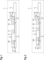
- Fig. 1 is a sectional view of the upper half of an actuation system 1.
- the actuation system 1 comprises an actuator 4 with a spindle 3 which is guiding a threaded tube 5.
- the spindle 3 is provided with a thread at its outer surface.
- the actuator 4 formed as an electric motor is used for rotating the spindle 3.
- a threaded tube 5 having a thread at its inner surface is engaged with the spindle 3.
- the threaded tube 5 is moved axially along the spindle 3.
- Fig. 1 it is visible that the threaded tube 5 is provided with connecting interfaces at its opposite sides.
- the connecting interfaces are formed as bayonet locks 6, 7.
- Fig. 1 shows the threaded tube 5 in a position when it is coupled with a shift fork 8.
- the shift fork 8 is also provided with a connecting interface in the form of a bayonet lock 9, which can be connected with the bayonet lock 7 of the threaded tube 5.
- the shift fork 8 is supported on the spindle 3 by a slide bearing 10, so that it can be moved along the axial direction.
- a second gear of a gearbox (not shown) is engaged, as is indicated by the "2" above the threaded tube 5.
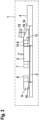
- Fig. 2 shows the actuation system 1 when the threaded tube 5 has been moved axially from the position shown in Fig. 1 by rotating the spindle 3. Due to the connection between the threaded tube 5 and the shift fork 8 the threaded tube 5 moves the shift fork 8 axially, in the illustration of Fig. 2 to the right-hand side.
- a first gear of a gearbox is engaged, as is indicated by the "1" above the threaded tube 5.
- a neutral position, indicated by an "N" is passed when the threaded tube 5 moves from the second gear position to the first gear position, indicated by an "1".
- a park element comprises a park cone 11, which co-operates with a park pawl 12.
- Park cone 11 and park pawl 12 are positioned at the right side of the spindle 3.
- the park cone 11 comprises a bayonet lock 13, which may be identical to the bayonet lock 9 of the shift fork 8.
- the park cone 11 has a cone-shaped surface 14, which interacts with a counter surface 15 of the park pawl 12, which is shaped in the opposite direction, so that both surfaces 14, 15 can slide on each other.
- the park cone 11 is not pushing the park pawl 12 into a park wheel 34.
- the threaded tube 5 is moved by a rotation of the spindle 3 from the position shown in Fig. 2 to the position shown in Fig. 3 , the bayonet lock 6 of the threaded tube 5 couples with the bayonet lock 13 of the park cone 11 due to a rotational movement of the threaded tube 5.
- the park cone 11 can be moved axially, so that the park pawl 12 slides on the cone-shaped surface 14, whereby the park pawl 12 is moved radially to the outer side.
- the park pawl 12 engages a park wheel (not shown), so that a movement of a vehicle comprising the gearbox is blocked.
- This parking position is indicated by a "P".
- the threaded tube 5 is rotated for connecting and disconnecting with the shift fork 8 and the park cone 14.
- the threaded tube 5 comprises a guiding groove 16 which is guiding a pin that is fixated at a support structure.
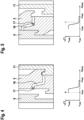
- Fig. 4 shows a circumferential view to visualize an exemplary shape and position of the guiding groove 16 at the outer surface of the threaded tube 5, the shift fork 8 and the park cone 11.
- Fig. 4 corresponds with the position of Fig. 3 , when the threaded tube 5 is connected to the park cone 11. In this position the pin 17, which is fixated at the support structure, is at the left side of the threaded tube 5.
- the threaded tube 5 is moved by a rotation of the spindle 3, in the view of Fig. 4 to the left side, the threaded tube 5 is rotated due to the shape of the guiding groove 16.
- the lower part of Fig. 4 shows the rotation angle ⁇ of the threaded tube 5 over the longitudinal axis position (s).
- Fig. 5 shows the position of the threaded tube 5 when it has reached the first gear position "1".
- the pin 17 has passed the curved part of the guiding groove 16.
- the threaded tube 5 is connected to the shift fork 8. In the lower part of Fig. 5 one can see that the rotation angle ⁇ is substantially lower compared to the parking position shown in Fig. 4 .
- Fig. 6 shows the position of the threaded tube 5 when it has reached the neutral position "N". In this position the pin 17 is in a portion of the guiding groove 16 which is parallel to the axial direction. The threaded tube 5 is still connected with the shift fork 8, but the shift fork 8 is opening all clutches resulting in no torque transmission of the gearbox.
- Fig. 7 shows the position of the threaded tube 5 when it has reached the second gear position "2".
- the pin 17 is now at the opposite end of the guiding groove 16 compared to the parking position shown in Fig. 4 .
- the threaded tube 5 has not been turned, it has only been moved axially.
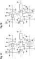
- Fig. 8 is a schematic view of the upper half of an arrangement for a gearbox.
- the structure of the gearbox comprises the actuation system 1, the actuator 4, a park cone 11 and a park pawl 12.
- the threaded tube 5 is connected to the shift fork 8.
- the input shaft 19 is connected with a gear shift sleeve 21 which can be moved axially by the shift fork 8.
- Fig. 8 shows a position, in which the gear shift sleeve 21 is engaged with a clutch 23 of a second gear wheel 25 as indicated by the "2" above the shift fork 8.
- the gear shift sleeve 21 can be moved axially so that it decouples from the clutch 23 and couples with a clutch 22 of a first gear wheel 24. Accordingly, the actuation system 1 can shift between a first gear and a second gear.
- the actuation system 1 has four shift states, as it can selectively shift a first gear, a neutral position, a second gear and a park position.
- Fig. 9 is a similar view as Fig. 8 , therefore identical components will not be explained in detail again.
- the clutches 22, 23 are arranged on the input shaft 19 of the gearbox.
- the park wheel 34 is connected with the first gear wheel 24.
- the function of the arrangement shown in Fig. 9 is basically the same as of the arrangement shown in Fig. 8 .
- Fig. 10 shows an arrangement where the clutches 22, 23 are positioned on an intermediate shaft 26 of the gearbox.
- the park wheel 34 is connected to the intermediate shaft 26.
- Fig. 11 shows a similar arrangement as Fig. 10 , where the clutches 22, 23 are positioned on an intermediate shaft 26 of the gearbox, whereas the park wheel 34 is connected to the first gear wheel 24.
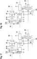
- Fig. 12 shows the position of an actuator axis 27, an input axis 28 and an intermediate axis 29 of another arrangement for a gearbox.
- Fig. 13 is a sectional view corresponding to Fig. 12 along the line XIII-XIII of Fig. 12 .
- Fig. 13 shows the arrangement in parking position, indicated by "P".
- the park cone 11 has been moved by the threaded tube 5 on the actuator axis 27 to the park pawl 12, so that a park wheel 34 is blocked.
- a clutch 23 is positioned, so that a gear shift sleeve 30 can connect a second gear wheel 32 with the input shaft 19.
- On the intermediate axis 29 a clutch 22 is positioned, so that a gear shift sleeve 33 can connect the first gear wheel 24 with the intermediate shaft 26.
- the clutch 22 of the intermediate axis 29 is closed, the clutch 23 of the input axis 28 is open and the park pawl 12 is closed.
- Reference number 31 is a first gear wheel, which is part of the input shaft 19.
- Fig. 14 shows the arrangement of Fig. 13 in the first gear position as indicated by the "1".
- the clutch 22 is closed, the clutch 23 is open and the park pawl 12 is open. Accordingly, the first gear wheel 24 is connected with the intermediate shaft 26.
- Fig. 15 shows the arrangement of Fig. 13 in the neutral position, as indicated by the “N”.
- the clutch 22 is open, the clutch 23 is also open and the park pawl 12 is open. In this state, neither the input shaft 19 nor the intermediate shaft 26 is connected.
- Fig. 16 shows the arrangement of Fig. 13 in the second gear position, as indicated by the "2”.
- the clutch 22 is open, the clutch 23 is closed and the park pawl 12 is open. Accordingly, the second gear wheel 32 is connected with the input shaft 19.
- Fig. 14 shows the arrangement of Fig. 13 in the first gear position as indicated by the "1".
- the clutch 22 is closed, the clutch 23 is open and the park pawl 12 is open. Accordingly, the first gear wheel 24 is connected
- FIG. 17 - 20 are sectional views of another arrangement having the axis positions as depicted in Fig. 12 .
- Fig. 17 is a sectional view corresponding to Fig. 12 along the line XIII-XIII of Fig. 12 .
- Fig. 17 shows the arrangement in parking position, as indicated by the "P".
- the clutch 22 is positioned on the intermediate axis 29 and the clutch 23 is positioned on the input axis 28.
- the spur gears namely the first gear wheel 31 and the second gear wheel 32, are arranged axially next to each other.
- the clutch 22 on the intermediate axis 29 is closed, the clutch 23 on the input axis 28 is open and the park pawl 12 is closed.
- Fig. 18 shows the arrangement of Fig. 17 in the first gear position, as indicated by the "1".
- the clutch 22 is closed, the clutch 23 is open, so that the first gear wheel 24 is connected with the intermediate shaft 26 and the park pawl 12 is open.
- Fig. 19 shows the arrangement of Fig. 17 in the neutral position, as indicated by the "N".
- the clutch 22 is open, the clutch 23 is open as well.
- the park pawl 12 is open. In this state, neither the input shaft 19 nor the intermediate shaft 26 is able to transfer torque.
- Fig. 20 shows the arrangement of Fig. 17 in the second gear position, as indicated by the "2".
- the clutch 22 is open, the clutch 23 is closed so that the second gear wheel 32 is connected with the input shaft 19.
Abstract
Actuation system (1), in particular for the actuation of movement elements of a gearbox, comprising: an actuator (4), a spindle (3) which can be driven by the actuator (4), a threaded tube (5) engaged with the spindle (3), wherein the threaded tube (5) is movable axially along the spindle (3), wherein the threaded tube (5) can be connected with one movement element at a time, either with a shift fork (8) or a park element,whereby, when the threaded tube (5) is connected with the shift fork (8), it can be moved between a first position, in which the threaded tube (5) closes a first shift element of a gearbox, a neutral position in which all shift elements are opened and no gearbox power transfer is possible, a third position, in which the threaded tube (5) closes a second shift element of the gearbox, and, when the threaded tube (5) is connected with the park element, it can be moved to a fourth position enabling actuation of the park element.
Description
- The invention relates to an actuation system, in particular for the actuation of movement elements of a gearbox.
- In a gearbox for an electric vehicle or a hybrid vehicle the actuation of a shift element is usually done by moving a clutch element part axially or radially. Basically, there are two main methods for the actuation of this movement. A hydraulic system allows the actuation of multiple movement elements, however, hydraulic systems are expensive, because several components are needed like a high-pressure pump, a hydraulic control unit, oil channels, filters and a pressure accumulator. In addition, a hydraulic system has increased cleanliness requirements.
- As an alternative, the actuation of a single movement element can be done electromechanically. Electro-mechanical actuation of a single movement element is cheaper compared to the hydraulic system. However, it enables only one linear or rotatory movement, which means that one actuator and one movement mechanism like a lever or a spindle can change the shift status of only one movement element. In this way it is e. g. possible to either shift a gear or to actuate a park mechanism. In case when a gearbox comprises two or more movement elements, including a park mechanism, usually a complicated and expensive hydraulic system or at least two electro-mechanical actuators including two separate movement mechanisms are required. Hence, adding shift functionality to a gearbox substantially increases costs, the number of parts and the size and weight of the gearbox.
- The object of the invention is to provide an actuating system for a gearbox with two or more movement elements having a simpler structure.
- This object is achieved by an actuation system with the features of
claim 1. - According to the invention an actuation system, in particular for the actuation of movement elements of a gearbox, is provided, comprising: an actuator, a spindle which can be driven by the actuator, a threaded tube engaged with the spindle, wherein the threaded tube is movable axially along the spindle, wherein the threaded tube can be connected with one movement element at a time, either with a shift fork or a park element, whereby, when the threaded tube is connected with the shift fork, it can be moved between a first position, in which the threaded tube closes a first shift element of a gearbox, a neutral position in which all shift elements are opened and no gearbox power transfer is possible, a third position, in which the threaded tube closes a second shift element of the gearbox, and, when the threaded tube is connected with the park element, it can be moved to a fourth position enabling actuation of the park element.
- The invention is based on the idea that a single electro-mechanical actuator can be used to shift at least two movement elements, like a shift fork or a park element. The inventive actuation system comprises a spindle having a threaded tube mounted to it with a thread. When the spindle is rotated by the actuator the threaded tube is moved axially along the longitudinal axis of the spindle between different positions. Each translatory position of the threaded tube is assigned to a specific rotatory position α. In a first translatory position or range the threaded tube is coupled with a first movement element of a gearbox, e.g. a shift fork. The threaded tube can only be coupled to a maximum of one movement element at the same time. By rotating the threaded tube, it can be decoupled and no shifting operation is possible. By a further translatory movement the threaded tube can be moved to a second position, in which it is coupled with a second movement element of a gearbox, like a park element or a park cone.
- The invention has several advantages. The inventive actuation system comprises only a small number of parts, leading to reduced costs, weight and a reduced size. A complicated hydraulic system is not necessary. Apart from other conventional actuators for a gearbox the inventive actuator has more shift functionalities including actuation of a park element, a park cone or a park lock.
- It is particularly preferred that the threaded tube of the inventive actuation system comprises a guiding groove on its outer surface and a pin or a room-position-fixated rotatable ball element is arranged at a support structure and engaged in the guiding groove of the threaded tube, wherein, when the threaded tube is moved axially, the threaded tube is turned around its longitudinal axis, connecting or disconnecting the threaded tube with or from one of the movement elements. It is also possible that several room-position-fixated rotatable ball elements are present, which can be fixed in a rotatable manner at a support structure like a wall of a housing. Such rotatable ball elements reduce friction between itself and the threaded tube.
- The pin, which is fixated at a support structure, for example a housing, defines a rotational angle (α) of the threaded tube. The groove has a certain shape which initiates a rotational movement of the threaded tube, because the pin is engaged with the groove. When the threaded tube is rotated, it can connect or disconnect with or from a movement element, either a shift fork or a park element, a park cone, a park roller or a piston.
- According to a preferred embodiment a movement element is a shift fork. A shift fork is used to open or close a shift element of a gearbox by moving a sliding sleeve axially, in order to connect or disconnect a loose gearwheel with an inner shaft. According to another preferred embodiment a movement element is a park element or a park cone. A park cone is used to move a park pawl in a radial direction, so that a park wheel of a gearbox can be blocked. When the park wheel is in the blocked position, a movement of the vehicle is disabled.
- According to a further development of the inventive actuation system the threaded tube is provided with two connecting interfaces, which are provided at opposite sides. Accordingly, the threaded tube can be moved in longitudinal direction of the spindle and it can selectively be connected to the first movement element or the second movement element. When the threaded tube is positioned in the middle, it is not connected to either the first movement element or the second movement element.
- It is preferred that a connecting interface is a bayonet lock, a clip, a pin in an undercut, a magnet, a one-way clutch or a dog clutch or a pretension element like a spring loaded ball in a groove or in an undercut. In general, the coupling element can be any kind of a mechanical connection which connects the threaded tube with the first or the second movement element.
- The movement element can be supported on the threaded tube by a slide bearing, which enables an axial movement of the movement element when it is engaged with the threaded tube.
- The invention is further related to an arrangement for a gearbox, comprising an inventive actuation system, a first movement element which is formed as a shift fork, which can selectively actuate a clutch for a first gear wheel or a clutch for a second gear wheel, and a second movement element which is formed as a park element or a park cone, which can move or rotate a park pawl into a locked position, or which is formed as a park roller, a lever or a camshaft. The inventive arrangement enables four different shift states and is able to shift two gears, to disconnect the drive train and to actuate one park pawl with a single actuator. The arrangement enables a reduction of costs and the number of parts, plus has a small size and a reduced weight compared to conventional solutions.
- According to a further development the arrangement comprises a park wheel, which can be locked by the park pawl. The park wheel can be arranged either on the input shaft of the gearbox or on an intermediate shaft of the gearbox. As an alternative, the park wheel can also be arranged on a gear wheel of the gearbox.
- The first shift element of the inventive arrangement can be positioned on an intermediate shaft or axis and the second movement element can be arranged on the input shaft or axis of the gearbox or vice versa. It is also possible to position both shift elements on the same axis.
- Exemplary embodiments of the invention will be explained in greater detail hereinafter with reference to the drawings, which show:
- Fig. 1
- a sectional view of a first embodiment of an inventive actuation system, whereby the actuator axis is in the second gear position;
- Fig. 2
- the actuation system shown in
Fig. 1 in the first gear position; - Fig. 3
- the actuation system shown in
Fig. 1 in the parking position; - Fig. 4
- a plane projection of the outer surface of actuator axis parts visualizing the position of the threaded tube with regard to a pin in the parking position;
- Fig. 5
- a similar view as
Fig. 4 when the threaded tube is in the first gear position; - Fig. 6
- a similar view as
Fig. 4 when the threaded tube is in the neutral position; - Fig. 7
- a similar view as
Fig. 4 when the threaded tube is in the second gear position; - Fig. 8
- a schematic view of a first inventive arrangement for a gearbox;
- Fig. 9
- a second embodiment of an arrangement for a gearbox;
- Fig. 10
- a third embodiment of an arrangement for a gearbox;
- Fig. 11
- a fourth embodiment of an arrangement for a gearbox;
- Fig. 12
- an exemplary position of the axes of a fifth arrangement for a gearbox;
- Fig. 13
- a sectional view of the arrangement shown in
Fig. 12 in the parking position; - Fig. 14
- a sectional view of the arrangement shown in
Fig. 12 in the first gear position; - Fig. 15
- a sectional view of the arrangement shown in
Fig. 12 in the neutral position; - Fig. 16
- a sectional view of the arrangement shown in
Fig. 12 in the second gear position; - Fig. 17
- a sectional view of a sixth embodiment of the arrangement shown in
Fig. 12 in the parking position; - Fig. 18
- a sectional view of the sixth embodiment of the arrangement shown in
Fig. 12 in the first gear position; - Fig. 19
- a sectional view of the sixth embodiment of the arrangement shown in
Fig. 12 in the neutral position; and - Fig. 20
- a sectional view of the sixth embodiment of the arrangement shown in
Fig. 12 in the second gear position. -
Fig. 1 is a sectional view of the upper half of anactuation system 1. Theactuation system 1 comprises anactuator 4 with aspindle 3 which is guiding a threadedtube 5. Thespindle 3 is provided with a thread at its outer surface. Theactuator 4 formed as an electric motor is used for rotating thespindle 3. A threadedtube 5 having a thread at its inner surface is engaged with thespindle 3. When thespindle 3 is rotated, the threadedtube 5 is moved axially along thespindle 3. - In
Fig. 1 it is visible that the threadedtube 5 is provided with connecting interfaces at its opposite sides. In this embodiment the connecting interfaces are formed asbayonet locks 6, 7. -
Fig. 1 shows the threadedtube 5 in a position when it is coupled with ashift fork 8. Theshift fork 8 is also provided with a connecting interface in the form of abayonet lock 9, which can be connected with the bayonet lock 7 of the threadedtube 5. Theshift fork 8 is supported on thespindle 3 by aslide bearing 10, so that it can be moved along the axial direction. In the position shown inFig. 1 a second gear of a gearbox (not shown) is engaged, as is indicated by the "2" above the threadedtube 5. -
Fig. 2 shows theactuation system 1 when the threadedtube 5 has been moved axially from the position shown inFig. 1 by rotating thespindle 3. Due to the connection between the threadedtube 5 and theshift fork 8 the threadedtube 5 moves theshift fork 8 axially, in the illustration ofFig. 2 to the right-hand side. When theshift fork 8 is in this position, a first gear of a gearbox is engaged, as is indicated by the "1" above the threadedtube 5. A neutral position, indicated by an "N", is passed when the threadedtube 5 moves from the second gear position to the first gear position, indicated by an "1". - When the
spindle 3 is further rotated, the threadedtube 5 is axially moved to the position shown inFig. 3 . Upon leaving the first gear position the bayonet lock 7 of the threadedtube 5 and thebayonet lock 9 of theshift fork 8 disconnect due to a rotation of the threadedtube 5, which will be explained later. - A park element comprises a
park cone 11, which co-operates with apark pawl 12.Park cone 11 andpark pawl 12 are positioned at the right side of thespindle 3. Thepark cone 11 comprises abayonet lock 13, which may be identical to thebayonet lock 9 of theshift fork 8. Thepark cone 11 has a cone-shapedsurface 14, which interacts with acounter surface 15 of thepark pawl 12, which is shaped in the opposite direction, so that bothsurfaces - In
Fig. 1 and 2 thepark cone 11 is not pushing thepark pawl 12 into apark wheel 34. When the threadedtube 5 is moved by a rotation of thespindle 3 from the position shown inFig. 2 to the position shown inFig. 3 , thebayonet lock 6 of the threadedtube 5 couples with thebayonet lock 13 of thepark cone 11 due to a rotational movement of the threadedtube 5. In this coupled state thepark cone 11 can be moved axially, so that thepark pawl 12 slides on the cone-shapedsurface 14, whereby thepark pawl 12 is moved radially to the outer side. In this position thepark pawl 12 engages a park wheel (not shown), so that a movement of a vehicle comprising the gearbox is blocked. This parking position is indicated by a "P". - As mentioned before, the threaded
tube 5 is rotated for connecting and disconnecting with theshift fork 8 and thepark cone 14. At its outer side the threadedtube 5 comprises a guidinggroove 16 which is guiding a pin that is fixated at a support structure. - The upper part of
Fig. 4 shows a circumferential view to visualize an exemplary shape and position of the guidinggroove 16 at the outer surface of the threadedtube 5, theshift fork 8 and thepark cone 11.Fig. 4 corresponds with the position ofFig. 3 , when the threadedtube 5 is connected to thepark cone 11. In this position thepin 17, which is fixated at the support structure, is at the left side of the threadedtube 5. When the threadedtube 5 is moved by a rotation of thespindle 3, in the view ofFig. 4 to the left side, the threadedtube 5 is rotated due to the shape of the guidinggroove 16. The lower part ofFig. 4 shows the rotation angle α of the threadedtube 5 over the longitudinal axis position (s). -
Fig. 5 shows the position of the threadedtube 5 when it has reached the first gear position "1". Thepin 17 has passed the curved part of the guidinggroove 16. The threadedtube 5 is connected to theshift fork 8. In the lower part ofFig. 5 one can see that the rotation angle α is substantially lower compared to the parking position shown inFig. 4 . -
Fig. 6 shows the position of the threadedtube 5 when it has reached the neutral position "N". In this position thepin 17 is in a portion of the guidinggroove 16 which is parallel to the axial direction. The threadedtube 5 is still connected with theshift fork 8, but theshift fork 8 is opening all clutches resulting in no torque transmission of the gearbox. -
Fig. 7 shows the position of the threadedtube 5 when it has reached the second gear position "2". Thepin 17 is now at the opposite end of the guidinggroove 16 compared to the parking position shown inFig. 4 . Between the neutral position shown inFig. 6 and the second gear position shown inFig. 7 the threadedtube 5 has not been turned, it has only been moved axially. -
Fig. 8 is a schematic view of the upper half of an arrangement for a gearbox. The structure of the gearbox comprises theactuation system 1, theactuator 4, apark cone 11 and apark pawl 12. The threadedtube 5 is connected to theshift fork 8. - A
drive unit 18, in this embodiment an electric motor, is connected to aninput shaft 19 of a gearbox. Through aspline 20 theinput shaft 19 is connected with agear shift sleeve 21 which can be moved axially by theshift fork 8.Fig. 8 shows a position, in which thegear shift sleeve 21 is engaged with a clutch 23 of asecond gear wheel 25 as indicated by the "2" above theshift fork 8. Through a movement of theshift fork 8 thegear shift sleeve 21 can be moved axially so that it decouples from the clutch 23 and couples with a clutch 22 of afirst gear wheel 24. Accordingly, theactuation system 1 can shift between a first gear and a second gear. When the threadedtube 5 moves thepark cone 11 to the park pawl 12 apark wheel 34 is blocked, so that a rotational movement of theinput shaft 19 is prevented. Altogether, theactuation system 1 has four shift states, as it can selectively shift a first gear, a neutral position, a second gear and a park position. -
Fig. 9 is a similar view asFig. 8 , therefore identical components will not be explained in detail again. In accordance with the arrangement ofFig. 8 theclutches input shaft 19 of the gearbox. Unlike the previous example thepark wheel 34 is connected with thefirst gear wheel 24. The function of the arrangement shown inFig. 9 is basically the same as of the arrangement shown inFig. 8 . -
Fig. 10 shows an arrangement where theclutches intermediate shaft 26 of the gearbox. Thepark wheel 34 is connected to theintermediate shaft 26. -
Fig. 11 shows a similar arrangement asFig. 10 , where theclutches intermediate shaft 26 of the gearbox, whereas thepark wheel 34 is connected to thefirst gear wheel 24. -
Fig. 12 shows the position of anactuator axis 27, aninput axis 28 and anintermediate axis 29 of another arrangement for a gearbox. -
Fig. 13 is a sectional view corresponding toFig. 12 along the line XIII-XIII ofFig. 12 .Fig. 13 shows the arrangement in parking position, indicated by "P". In this state thepark cone 11 has been moved by the threadedtube 5 on theactuator axis 27 to thepark pawl 12, so that apark wheel 34 is blocked. On the input axis 28 a clutch 23 is positioned, so that agear shift sleeve 30 can connect asecond gear wheel 32 with theinput shaft 19. On the intermediate axis 29 a clutch 22 is positioned, so that agear shift sleeve 33 can connect thefirst gear wheel 24 with theintermediate shaft 26. In the parking position, as depicted inFig. 13 , the clutch 22 of theintermediate axis 29 is closed, the clutch 23 of theinput axis 28 is open and thepark pawl 12 is closed.Reference number 31 is a first gear wheel, which is part of theinput shaft 19. -
Fig. 14 shows the arrangement ofFig. 13 in the first gear position as indicated by the "1". The clutch 22 is closed, the clutch 23 is open and thepark pawl 12 is open. Accordingly, thefirst gear wheel 24 is connected with theintermediate shaft 26.Fig. 15 shows the arrangement ofFig. 13 in the neutral position, as indicated by the "N". The clutch 22 is open, the clutch 23 is also open and thepark pawl 12 is open. In this state, neither theinput shaft 19 nor theintermediate shaft 26 is connected.Fig. 16 shows the arrangement ofFig. 13 in the second gear position, as indicated by the "2". The clutch 22 is open, the clutch 23 is closed and thepark pawl 12 is open. Accordingly, thesecond gear wheel 32 is connected with theinput shaft 19.Fig. 17 - 20 are sectional views of another arrangement having the axis positions as depicted inFig. 12 .Fig. 17 is a sectional view corresponding toFig. 12 along the line XIII-XIII ofFig. 12 .Fig. 17 shows the arrangement in parking position, as indicated by the "P". In accordance with the previous embodiment the clutch 22 is positioned on theintermediate axis 29 and the clutch 23 is positioned on theinput axis 28. Unlike the last embodiment depicted inFig. 13 - 16 the spur gears, namely thefirst gear wheel 31 and thesecond gear wheel 32, are arranged axially next to each other. In the parking position shown inFig. 17 the clutch 22 on theintermediate axis 29 is closed, the clutch 23 on theinput axis 28 is open and thepark pawl 12 is closed. -
Fig. 18 shows the arrangement ofFig. 17 in the first gear position, as indicated by the "1". The clutch 22 is closed, the clutch 23 is open, so that thefirst gear wheel 24 is connected with theintermediate shaft 26 and thepark pawl 12 is open. -
Fig. 19 shows the arrangement ofFig. 17 in the neutral position, as indicated by the "N". The clutch 22 is open, the clutch 23 is open as well. Thepark pawl 12 is open. In this state, neither theinput shaft 19 nor theintermediate shaft 26 is able to transfer torque. -
Fig. 20 shows the arrangement ofFig. 17 in the second gear position, as indicated by the "2". The clutch 22 is open, the clutch 23 is closed so that thesecond gear wheel 32 is connected with theinput shaft 19. -
- 1
- actuation system
- 3
- spindle
- 4
- actuator
- 5
- threaded tube
- 6
- bayonet lock
- 7
- bayonet lock
- 8
- shift fork
- 9
- bayonet lock
- 10
- slide bearing
- 11
- park cone
- 12
- park pawl
- 13
- bayonet lock
- 14
- surface
- 15
- counter surface
- 16
- guiding groove
- 17
- pin
- 18
- drive unit
- 19
- input shaft
- 20
- spline
- 21
- gear shift sleeve
- 22
- clutch
- 23
- clutch
- 24
- first gear wheel
- 25
- second gear wheel
- 26
- intermediate shaft
- 27
- actuator axis
- 28
- input axis
- 29
- intermediate axis
- 30
- gear shift sleeve
- 31
- first gear wheel
- 32
- second gear wheel
- 33
- gear shift sleeve
- 34
- park wheel
Claims (14)
- Actuation system (1), in particular for the actuation of movement elements of a gearbox, comprising:- an actuator (4),- a spindle (3) which can be driven by the actuator (4),- a threaded tube (5) engaged with the spindle (3),wherein the threaded tube (5) is movable axially along the spindle (3), wherein the threaded tube (5) can be connected with one movement element at a time, either with a shift fork (8) or a park element,
whereby, when the threaded tube (5) is connected with the shift fork (8), it can be moved between a first position, in which the threaded tube (5) closes a first shift element of a gearbox, a neutral position in which all shift elements are opened and no gearbox power transfer is possible, a third position, in which the threaded tube (5) closes a second shift element of the gearbox, and, when the threaded tube (5) is connected with the park element, it can be moved to a fourth position enabling actuation of the park element. - Actuation system according to claim 1, wherein the threaded tube (5) comprises a guiding groove (16) at its outer surface and a pin (17) or a room-position-fixated rotatable ball element is arranged at a support structure and engaged in the guiding groove (16) of the threaded tube (5), wherein, when the threaded tube (5) is moved axially, the threaded tube (5) is turned around its longitudinal axis, connecting or disconnecting the threaded tube (5) with or from one of the movement elements.
- Actuation system according to claim 1 or 2, wherein a movement element is a shift fork (8), a park cone (11), a park element, a park roller, al lever or a piston.
- Actuation system according to any of the preceding claims, wherein the threaded tube (5) is provided with two connecting interfaces, which are provided at opposite sides.
- Actuation system according to claim 4, wherein a connecting interface is a bayonet lock (6, 7, 9, 13), a clip, a pin in an undercut, a magnet, a one-way clutch, a dog clutch or a pretension element like a spring loaded ball in a groove or in an undercut.
- Actuation system according to any of the preceding claims, wherein a movement element is supported on the spindle (3) by a slide bearing (10), a ball spindle or directly with part to part contact.
- Actuation system according to any of claims 2 to 6, wherein the shape of the guiding groove (16) is determined such that the threaded tube (5) follows a specific movement curve when it is driven by the spindle (3).
- Actuation system according to any of the preceding claims, wherein a linear movement of the threaded tube (5) is effected by a combination of an electro-mechanical actuator (4) with the spindle (3) or an electro-mechanical linear actuator or a mechanical actuation.
- Actuation system according to any of the preceding claims, wherein the park element comprises a spring element enabling damping during operation.
- Arrangement for a gearbox, comprising:- an actuation system (1) according to any one of claims 1 to 9,- a first movement element which is formed as a shift fork (8) which can selectively actuate a clutch (22) for a first gear wheel (24) or a clutch (23) for a second gear wheel (25), and- a second movement element which is formed as a park element or as a park roller, a lever or a camshaft, which can move a park pawl (12) into a locked position.
- Arrangement according to claim 10, wherein a park wheel (34), which can be locked by the park pawl (12), is arranged either on the input shaft (19) of the gearbox or on an intermediate shaft (26) of the gearbox or on a gear wheel (24, 25) of the gearbox.
- Arrangement according to claim 10 or 11, wherein the first shift element is arranged on an intermediate axis (29) and the second shift element is arranged on an input axis (28) of the gearbox.
- Arrangement according to any of claims 10 to 12, wherein a shift element is a friction disc plate, a synchronizer, a dog clutch or a one way clutch.
- Arrangement according to any of claims 10 to 13, wherein a drive unit (18) is connected to an input shaft (19) of the gearbox from the left or right side.
Priority Applications (2)
| Application Number | Priority Date | Filing Date | Title |
|---|---|---|---|
| EP22168007.7A EP4261438A1 (en) | 2022-04-12 | 2022-04-12 | Actuation system for the actuation of movement elements of a gearbox and arrangement for a gearbox comprising the actuation system |
| CN202310388914.9A CN116906566A (en) | 2022-04-12 | 2023-04-12 | Actuation system and device for a gearbox comprising an actuation system |
Applications Claiming Priority (1)
| Application Number | Priority Date | Filing Date | Title |
|---|---|---|---|
| EP22168007.7A EP4261438A1 (en) | 2022-04-12 | 2022-04-12 | Actuation system for the actuation of movement elements of a gearbox and arrangement for a gearbox comprising the actuation system |
Publications (1)
| Publication Number | Publication Date |
|---|---|
| EP4261438A1 true EP4261438A1 (en) | 2023-10-18 |
Family
ID=81307511
Family Applications (1)
| Application Number | Title | Priority Date | Filing Date |
|---|---|---|---|
| EP22168007.7A Pending EP4261438A1 (en) | 2022-04-12 | 2022-04-12 | Actuation system for the actuation of movement elements of a gearbox and arrangement for a gearbox comprising the actuation system |
Country Status (2)
| Country | Link |
|---|---|
| EP (1) | EP4261438A1 (en) |
| CN (1) | CN116906566A (en) |
Citations (2)
| Publication number | Priority date | Publication date | Assignee | Title |
|---|---|---|---|---|
| US20210010590A1 (en) * | 2019-07-08 | 2021-01-14 | Hyundai Motor Company | Shifting actuator for transmission |
| WO2021069024A1 (en) * | 2019-10-10 | 2021-04-15 | Schaeffler Technologies AG & Co. KG | Transmission and parking lock actuation device; transmission; and electric drive unit |
-
2022
- 2022-04-12 EP EP22168007.7A patent/EP4261438A1/en active Pending
-
2023
- 2023-04-12 CN CN202310388914.9A patent/CN116906566A/en active Pending
Patent Citations (2)
| Publication number | Priority date | Publication date | Assignee | Title |
|---|---|---|---|---|
| US20210010590A1 (en) * | 2019-07-08 | 2021-01-14 | Hyundai Motor Company | Shifting actuator for transmission |
| WO2021069024A1 (en) * | 2019-10-10 | 2021-04-15 | Schaeffler Technologies AG & Co. KG | Transmission and parking lock actuation device; transmission; and electric drive unit |
Also Published As
| Publication number | Publication date |
|---|---|
| CN116906566A (en) | 2023-10-20 |
Similar Documents
| Publication | Publication Date | Title |
|---|---|---|
| CN102667260B (en) | Shifting device for a gearbox | |
| USRE46242E1 (en) | Device for actuating a gearwheel, which is designed as a loose wheel, of a transmission device | |
| US7669495B2 (en) | Transmission for vehicles | |
| US7581461B2 (en) | Transmission for vehicles | |
| US8196725B2 (en) | Device for the rotationally fixed connection of a shaft to at least one component mounted to rotate on the shaft | |
| US11746898B2 (en) | Actuator arrangement for electric drive | |
| US8202187B2 (en) | Crank-CVT transmission | |
| US20130192398A1 (en) | Dual Clutch Transmission And Dual Clutch Actuators Thereof | |
| US20030051964A1 (en) | Torque transfer device | |
| US10495223B2 (en) | Shift by wire parking system | |
| EP2143979B1 (en) | Double-clutch gearchange | |
| EP4261438A1 (en) | Actuation system for the actuation of movement elements of a gearbox and arrangement for a gearbox comprising the actuation system | |
| CN114531896A (en) | A transmission and a parking lock manipulation apparatus; a transmission; and an electric drive unit | |
| EP3670970B1 (en) | A transmission for a vehicle | |
| JP2022542416A (en) | Shift drum assembly and transmission assembly with such shift drum assembly | |
| RU2360158C2 (en) | Clutch coupling | |
| JP7412554B2 (en) | Actuator devices and transmission devices equipped with such actuator devices | |
| KR102241482B1 (en) | Actuating device with a master cylinder actuable by a gear selector drum for actuating the clutch | |
| US8172715B2 (en) | Multiplexed gear actuation system for a dual clutch transmission | |
| US7418884B2 (en) | Switching device | |
| CN115030995A (en) | Module for a system for synchronizing and driving the countershafts of a gearbox of a transmission | |
| KR20070038457A (en) | Clutch |
Legal Events
| Date | Code | Title | Description |
|---|---|---|---|
| PUAI | Public reference made under article 153(3) epc to a published international application that has entered the european phase |
Free format text: ORIGINAL CODE: 0009012 |
|
| STAA | Information on the status of an ep patent application or granted ep patent |
Free format text: STATUS: THE APPLICATION HAS BEEN PUBLISHED |
|
| AK | Designated contracting states |
Kind code of ref document: A1 Designated state(s): AL AT BE BG CH CY CZ DE DK EE ES FI FR GB GR HR HU IE IS IT LI LT LU LV MC MK MT NL NO PL PT RO RS SE SI SK SM TR |