EP4261128A1 - Floating unit for lifting a bendable connection element and supply system for a floating unit - Google Patents
Floating unit for lifting a bendable connection element and supply system for a floating unit Download PDFInfo
- Publication number
- EP4261128A1 EP4261128A1 EP23162581.5A EP23162581A EP4261128A1 EP 4261128 A1 EP4261128 A1 EP 4261128A1 EP 23162581 A EP23162581 A EP 23162581A EP 4261128 A1 EP4261128 A1 EP 4261128A1
- Authority
- EP
- European Patent Office
- Prior art keywords
- floating unit
- interface
- unit
- connection element
- floating
- Prior art date
- Legal status (The legal status is an assumption and is not a legal conclusion. Google has not performed a legal analysis and makes no representation as to the accuracy of the status listed.)
- Granted
Links
Images



Classifications
-
- B—PERFORMING OPERATIONS; TRANSPORTING
- B64—AIRCRAFT; AVIATION; COSMONAUTICS
- B64B—LIGHTER-THAN AIR AIRCRAFT
- B64B1/00—Lighter-than-air aircraft
- B64B1/66—Mooring attachments
-
- B—PERFORMING OPERATIONS; TRANSPORTING
- B64—AIRCRAFT; AVIATION; COSMONAUTICS
- B64C—AEROPLANES; HELICOPTERS
- B64C39/00—Aircraft not otherwise provided for
- B64C39/02—Aircraft not otherwise provided for characterised by special use
- B64C39/022—Tethered aircraft
-
- B—PERFORMING OPERATIONS; TRANSPORTING
- B64—AIRCRAFT; AVIATION; COSMONAUTICS
- B64B—LIGHTER-THAN AIR AIRCRAFT
- B64B1/00—Lighter-than-air aircraft
- B64B1/40—Balloons
- B64B1/50—Captive balloons
-
- B—PERFORMING OPERATIONS; TRANSPORTING
- B64—AIRCRAFT; AVIATION; COSMONAUTICS
- B64U—UNMANNED AERIAL VEHICLES [UAV]; EQUIPMENT THEREFOR
- B64U10/00—Type of UAV
- B64U10/30—Lighter-than-air aircraft, e.g. aerostatic aircraft
-
- B—PERFORMING OPERATIONS; TRANSPORTING
- B64—AIRCRAFT; AVIATION; COSMONAUTICS
- B64U—UNMANNED AERIAL VEHICLES [UAV]; EQUIPMENT THEREFOR
- B64U10/00—Type of UAV
- B64U10/60—Tethered aircraft
-
- B—PERFORMING OPERATIONS; TRANSPORTING
- B64—AIRCRAFT; AVIATION; COSMONAUTICS
- B64U—UNMANNED AERIAL VEHICLES [UAV]; EQUIPMENT THEREFOR
- B64U70/00—Launching, take-off or landing arrangements
- B64U70/90—Launching from or landing on platforms
- B64U70/92—Portable platforms
- B64U70/93—Portable platforms for use on a land or nautical vehicle
-
- A—HUMAN NECESSITIES
- A01—AGRICULTURE; FORESTRY; ANIMAL HUSBANDRY; HUNTING; TRAPPING; FISHING
- A01B—SOIL WORKING IN AGRICULTURE OR FORESTRY; PARTS, DETAILS, OR ACCESSORIES OF AGRICULTURAL MACHINES OR IMPLEMENTS, IN GENERAL
- A01B76/00—Parts, details or accessories of agricultural machines or implements, not provided for in groups A01B51/00 - A01B75/00
-
- B—PERFORMING OPERATIONS; TRANSPORTING
- B64—AIRCRAFT; AVIATION; COSMONAUTICS
- B64U—UNMANNED AERIAL VEHICLES [UAV]; EQUIPMENT THEREFOR
- B64U10/00—Type of UAV
-
- B—PERFORMING OPERATIONS; TRANSPORTING
- B64—AIRCRAFT; AVIATION; COSMONAUTICS
- B64U—UNMANNED AERIAL VEHICLES [UAV]; EQUIPMENT THEREFOR
- B64U2101/00—UAVs specially adapted for particular uses or applications
-
- B—PERFORMING OPERATIONS; TRANSPORTING
- B64—AIRCRAFT; AVIATION; COSMONAUTICS
- B64U—UNMANNED AERIAL VEHICLES [UAV]; EQUIPMENT THEREFOR
- B64U2101/00—UAVs specially adapted for particular uses or applications
- B64U2101/40—UAVs specially adapted for particular uses or applications for agriculture or forestry operations
-
- B—PERFORMING OPERATIONS; TRANSPORTING
- B64—AIRCRAFT; AVIATION; COSMONAUTICS
- B64U—UNMANNED AERIAL VEHICLES [UAV]; EQUIPMENT THEREFOR
- B64U2101/00—UAVs specially adapted for particular uses or applications
- B64U2101/45—UAVs specially adapted for particular uses or applications for releasing liquids or powders in-flight, e.g. crop-dusting
Definitions
- the spring force of the valve spring may press the closing member against the seat in addition to the pressure of the fluid in the envelope.
- the spring force may be adjusted to a minimum force to be overcome before fluid may be introduced into the envelope.
- the first interface may include a first electrical interface.
- the clamping unit may include an actuator connected with first electrical interface for supplying the actuator with electrical energy.
- the actuator may be configured to switch the clamping unit into the released state when the actuator is energized with electrical energy and to switch the clamping unit into the fixed state when the actuator is deenergized.
- the actuator may be a combination of a solenoid and a mechanical spring.
- the spring In the fixed state, the spring may press against the bendable connection element and thus cause a friction force for clamping the clamping unit to the bendable connection element.
- the solenoid In the released state, the solenoid may be energized and may retract the mechanical spring back from the bendable connection element.
- the clamping unit can switch automatically into the fixed state in case of a loss of electric energy due to the spring force.
- the clamping unit may comprise for example a battery to provide the electrical energy needed for the clamping unit.
- the actuator may be of any other type, for example an electrical motor.
- the first electrical interface may be connectable with an energy source supplying the electrical energy.
- the first electrical interface may be an inductive interface for a contactless transfer of electrical energy.
- the first electrical interface may comprise a connector, a plug or pins for a mechanical connection with an energy source or another electrical interface.
- the first electrical interface may be connected with the actuator to control or supply the actuator with electrical energy.
- a further aspect provides a supply system for a floating unit including at least one floating unit, a bendable connection element and a platform.
- the platform includes at least one connection point for the at least one floating unit.
- the connection point includes at least one additional interface for connecting the first interface of the at least one floating unit when the clamping unit of the at least one floating unit is aligned with the at least one connection point.
- the bendable connection element is threaded through the clamping unit of the at least one floating unit.
- the at least one floating unit may be designed as described before.
- a connection point defines a fixed position where a floating unit can be stored.
- the platform may include for each floating unit a separate connection point.
- the first interface of the floating unit and the additional interface of the connection point may be connected so that energy or any working fluid for driving or operating the floating unit can be transferred from one interface to the other interface.
- a fluid can be transferred from one interface to the other interface for adjusting the gas volume of the envelope.
- the gas volume may be increased or decreased.
- the bendable connection element may be threaded through the clamping unit in such a way that the floating unit including the clamping unit may be removed from the bendable connection element, for example to replace a damaged floating unit by another.
- the floating unit may also be moveable along the bendable connection element when the clamping unit is in the released state without dropping down from the bendable connection element.
- the sealing may be moved in the sealing position when the bore is pressurized with a fluid.
- Fluid may be transferred under pressure from the bore to the envelope of the floating unit via the additional fluidic interface and the first fluidic interface for adjusting the gas volume of the envelope.
- the pressure of the fluid may exert a force on the sealing to move the sealing into the sealing position. I. e., there is no need for an additional actuator for moving the sealing.
- the at least one floating unit may be placed at the at least one connection point and the sealing moved in the sealing position may be protruding into the first fluidic interface of the floating unit.
- the additional interface may include at least one additional electrical interface for connecting the first electrical interface of the at least one floating unit.
- the at least one additional electrical interface may be energized with electrical energy when the first electrical interface of the at least one floating unit is connected with the at least one additional electrical interface.
- the first electrical interface of the at least one floating unit may be connected with the at least one additional electrical interface when the at least one floating unit is positioned at a connection point. If so, the magnetic force may attract the floating unit to the platform so that the floating unit will be hold at the connection point. Electrical energy may be transferred from the additional electrical interface to the first electrical interface for controlling or supplying the actuator of the clamping unit with electrical energy. The electrical energy may be used to switch the actuator into the released state and/or to hold the actuator in the released state so that the bendable connection element can be moved freely through the clamping unit while the floating unit is standing still at the connection point.
- the supply system may include a winch for winding up the bendable connection element.
- the supply system may also include a guidance for guiding the bendable connection element in alignment with the at least one connection point.
- the supply system may include more than one connection point.
- the distance between two connection points may be adapted for a gapless positioning of the clamping units at the connection points next to each other.
- the floating units can be stored very compact since a clamping unit of one floating unit positioned at a connection point may be adjacent to a clamping unit of another floating unit positioned at a connection point.
- the supply system may also include a base body wherein the platform is rotatably connected to the base body.
- the base body may be a solid element and may be mounted on a static station or on a mobile vehicle such as an agricultural vehicle (e. g. a tractor or harvester).
- the platform may rotate about a vertical axis connected with the base body.
- the orientation of the platform may be aligned to any object as for example a section of the bendable connection element beyond the supply system that may float in any direction.
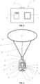
- FIG. 1 and FIG. 2 show a supply system 1.
- the supply system 1 comprises a platform 3, a vehicle 2, a bendable connection element 4 having one end connected with the vehicle 2 and another end connected with the platform 3 and at least one floating unit 5, 6, 7, 8 and 9 for lifting the bendable connection element 4, a winch 10 for for winding or unwinding of the bendable connection element 4 and a control unit 13.
- Vehicle 2 may be a drone.
- the platform 3 of the supply system 1 is mounted on a base body 47 designed as a roof of an agricultural vehicle 11.
- the base body 47 comprises a vertical axis about which the platform 3 is rotatably connected to the base body 47 (see FIG. 5 ).
- the agricultural vehicle 11 may be of any type as for example a tractor or a harvester.
- the vehicle 2 is placed on the roof of the agricultural vehicle 11.
- the agricultural vehicle 11 comprises a sensor 12 for determining a height 15 of an obstacle 14 in front of the agricultural vehicle 11.
- the obstacle 14 may be crop to be harvested by the agricultural vehicle 11.
- the control unit 13 is integrated in the agricultural vehicle 11. Alternatively, the control unit 13 can be integrated in the supply system 1.
- the control unit 13 receives signals from the sensor 12 and is configured to control the components of the supply system 1. Additionally, the control unit 13 may be configured to control also components of the agricultural vehicle 11 such an engine.
- FIG. 1 the floating units 5 to 9 are stored on the platform 3, the bendable connection element 4 is wound up by the winch 10 and vehicle 2 is placed on the roof of the agricultural vehicle 11.
- Each floating unit 5 to 9 may be filled with a fluid, such as helium, to generate a buoyant force so that the floating units 5 to 9 may float and carry the bendable connection element 4 in the air.
- FIG. 2 shows the vehicle 2 flying in front of the agricultural vehicle 11. The vehicle 2 connected with the bendable connection element 4 has unwound the bendable connection element 4 partly from the winch 10.
- FIG. 3 shows the control unit 13 comprising an interface 16, a controller 17 and a memory 18.
- the control unit 13 may receive and send signals or data via the interface 16.
- the interface 16 may be a wireless interface or a connector.
- the controller 17 may store the data or signals received by the control unit 13 in the memory 18.
- the memory 18 may contain additional data or executable programs, for example in terms of a computer-implemented method, that may be retrieved, processed or carried out by the controller 17. Data or signals resulting from the processing of data or signals or from the execution of a program may be stored to the memory 18 or sent to the interface 16 by the controller 17.
- FIG. 4 shows any one of the at least one floating units 5 to 9.
- the floating unit comprises a clamping unit 19 switchable between a fixed state for attaching the floating unit to the bendable connection element 4 and a released state for detaching the floating unit from the bendable connection element 4.
- the floating unit also comprises an envelope 20 for enclosing a gas volume 21.
- the envelope 20 may be filled with a fluid, such as helium, to generate a buoyant force so that the floating unit may float in the air.
- a rope 33 connects the envelope 20 with the clamping unit 19. The rope 33 is guided in a protective sleeve 32 to avoid a damage of the rope 33.
- the clamping unit 19 comprises an actuator 22 configured to switch into the released state when the actuator 22 is energized with electrical energy and to switch into the fixed state when the actuator 22 is deenergized.
- the actuator 22 is connected with a first electrical interface 29 via a power line 30 and may be energized by an external power supply connected to the first electrical interface 29.
- the actuator 22 may be connected to the bendable connection element 4 via a power line 31 and may be energized by a power supply connected with the bendable connection element 4.
- the first electrical interface 29 may receive energy by inductive loading via the current / voltage passing through the bendable connection element 4.
- the actuator 22 is connected to an internal battery 34 integrated in the clamping unit 19 and connected to the power line 30. The battery 34 may energize the actuator 22 if needed.
- the clamping unit 19 also comprises a first fluidic interface 23 and a conduit 24 connecting the first fluidic interface 23 and the envelope 20 for supplying the gas volume 21 with a fluid such as helium.
- the first fluidic interface 23 comprises a check valve 25 to avoid a loss of fluid draining out of the first fluidic interface 23. The detailed working principle of the first fluidic interface 23 will be described later on.
- the clamping unit 19 comprises a tapering 35 at the top of the clamping unit 19.
- the shape of the clamping unit 19 is rotationally symmetric.
- connection point 38 to 41 comprises an additional electrical interface 59 and an additional fluidic interface 58 as can be seen in FIG. 6 and FIG. 7 for connecting the first electrical interface 29 and the first fluidic interface 23 of a floating unit positioned at one of the connection points.
- the first electrical interface 29 and the additional electrical interface 59 are designed as an inductive electrical interface so that energy may be transferred from one interface to the other even if a gap is between the two interfaces.
- the first electrical interface 29 and the additional electrical interface 59 may be used as an inductive charging interface to charge the battery 34 of a clamping unit 19. Both interfaces may also be used to transfer signals, e. g. to control the actuator 22 of the clamping unit 19 or to control the battery 34.
- the winch 10 is driven to wind up the bendable connection element 4.
- the bendable connection element 4 is guided above the connection points 38 to 41 so that each floating unit 5 to 9 can be pulled to a connection point.
- An extension 50 of the platform 3 comprises a guidance 56 through which the bendable connection element 4 is guided to keep the bendable connection element 4 aligned with the connection points.
- the bendable connection element 4 moves freely through each clamping unit 19 of the floating units 7 to 9 already stored at the platform 3 since these clamping units 19 are in the released state. Instead, clamping unit 19 of the floating unit 5 is in the fixed state and is pulled by the bendable connection element 4 in direction to the connection point 38.
- the floating unit 5 approaches a rail system 43 of the platform 3.
- the rail system 43 is also shown in FIG. 6 in a cross-sectional view. It comprises a left rail 64 and a right rail 44 for guiding the clamping unit 19 of the floating unit 5 towards the connection points.
- the rails are formed of pressed steel metal. Pillars are provided to position the rails relative to platform 3.
- the left rail 64 is fixed to the platform 3 by means of a left pillar 57 and the right rail 44 is fixed to the platform 3 by means of a right pillar 46 at a first area.
- FIG. 1 Further pillars are indicated with right pillar 45 for connection with the right rail 44 while pillar 57 and further rails for connection of a left rail 64 are omitted for clarity reasons.
- the left and right rails 44 and 64 may be connected to the pillars by screws or by a weld joint.
- the left and right rails 44 and 64 are fixed to the extension 50 of the platform 3.
- Left and right rails 44 and 64 are spaced apart so that the clamping unit 19 of each floating unit 5 to 9 can slide therebetween.
- the left and the right rail 44 and 64 comprise an intermediate portion 49 having a first profile 63 and a catching portion 48 having a second profile 60.
- the profiles can be seen in FIG. 6 .
- the intermediate portion 49 extends horizontally from the extension 50 to the pillars 46, 57 positioned close to the connection point 38. Thus, the intermediate portion 49 provides a correct positioning of the clamping units 19 at their connection points.
- the rounded contour 61 of the left and right rail 44 and 64 opening upwards to the top enables that the protective sleeve 32 of the floating unit can pass.
- the protective sleeve 32 keeps the rope 33 distant of rail system 43 to avoid that the rope 33 is not unintentionally entangled with one of the rails 44 or 64.
- the catching portion 48 may be rotatable in a horizontal transvers direction to enable the adaption to different operating height. Thereby it can be prohibited that the catching portion 48 is catching an envelope 20 instead of a clamping unit 19 of a floating unit.
- connection point 38 While the winch 10 winds up the bendable connection element 4 the floating unit 5 is pulled in a horizontal and vertical direction towards the connection point 38 and the clamping unit 19 of the floating unit 5 will be caught by the catching portion 48 of the rail system 43. Then, the clamping unit 19 will be guided by the rails 44 and 64 and will slide between the left rail 64 and the right rail 44 of the rail system 43.
- the bendable connection element 4 pulls the floating unit 5 until the floating unit 5 reaches the next free connection point, here connection point 38.
- the shape of the rail system 43 guides the clamping unit 19 of the floating unit 5 downwards so that the clamping unit 19 of the floating unit 5 will be aligned with the connection point 38 of the platform 3.
- the first electrical interface 29 of the floating unit 5 will be energized by the additional electrical interface 59 of the connection point 38.
- the electrical energy will then be transferred from the first electrical interface 29 to the actuator 22 of the clamping unit 19 of the floating unit 5 to switch the clamping unit 19 from the fixed state to the released state so that the bendable connection element 4 can also freely pass through the clamping unit 19 of the floating unit 5 analogously to the other floating unit 7 to 9 stored at the platform 3.
- the clamping unit 19 of the floating unit 5 leans against the adjacent clamping unit 19 of the floating unit 7 and is not able to move further with the bendable connection element 4 winded up by the winch 10. But there may be a slight time delay between the positioning of the clamping unit 19 of the floating unit 5 at the connection point 38 and the switch of clamping unit 19 into released state. I. e., the clamping unit 19 of the floating unit 5 being still in the fixed state blocks the movement of the bendable connection element 4 during the time delay so that the bendable connection element 4 is tightened and changes its routing as indicated by the dotted bendable connection element 51.
- the bendable connection element 4 presses against a strain relief 52 arranged between the extension 50 and the winch 10 as can be seen in FIG. 5 .
- the strain relief 52 comprising a slider 54 mounted horizontally moveable in the extension 50 and a roller biased by a spring 53 against the bendable connection element 4 is switchable between a tensioned state and a reliefing state.
- the spring 53 presses the bendable connection element 4 with the roller towards the winch 10.
- the strain relief 52 the strain relief 52 is retracted by the bendable connection element 4 so that the roller changes its position to a roller position 55.
- the retraction of the strain relief 52 enables that a short part of the bendable connection element 4 can still be wound up by the winch 10 until the clamping unit 19 of the floating unit 5 has switched into the released state. After the clamping unit 19 releases the bendable connection element 4 the spring 53 presses the strain relief 52 to the position of the tensioned state again. So, the winch 10 wouldn't be interrupted winding up of the bendable connection element 4 even when a floating unit is positioned at a connection point and thereby blocks the movement of the bendable connection element 4 for a short moment. In addition, a damage caused by the blocked bendable connection element 4 can be prevented.
- the floating unit 5 can be fluidically connected to the connection point 38 analogously to the other floating units 7 to 9 already stored at the platform 3 when the floating unit 5 is stored at the platform 3.
- the process of fluidically connecting a floating unit to the platform 3 is for all floating units 5 to 9 the same and will be explained now by way of example of FIG. 6 and FIG. 7 .
- the first fluidic interface 23 is connected with the conduit 24 and comprises the check valve 25 including a seat 69 and a closing member 68 actuatable by a valve spring 67.
- the valve spring 67 biases the closing member 68 towards the seat 69 to block the conduit 24.
- the pressure of the fluid within the envelope 20 may press the closing member 68 towards the seat 69.
- the closing member 68 is designed as a ball and the seat 69 is inclined so that the ball is pressed against the seat 69 to avoid a leakage and a reverse flow of fluid coming through check valve 25 from the envelope 20 of the floating unit.
- the interface 16 of the control unit 13 is connected with the additional electrical interface 59 and detects when the first electrical interface 29 of the clamping unit 19 of the floating unit is connected with the additional electrical interface 59 to determine that the floating unit is stored at the connection point in an adequate position for starting the fluid supply process.
- the fluid coming from the bore 42 is transferred from the additional fluidic interface 58 to the first fluidic interface 23 and presses against the closing member 68 of the check valve 25.
- the pressure within the bore 42 is high enough the fluid compresses the valve spring 67 and opens the check valve 25 so that the fluid is pressed into the conduit 24.
- the pressure transfers the fluid through the conduit 24 into the envelope 20 of the floating unit (see FIG. 6 ).
- bore 42, conduit 24 and the envelope 20 are fluidically connected so that fluid may be added or released for adjusting the gas volume 21 of the envelope 20.
- the control unit 13 may determine the pressure of the fluid to control the amount of fluid to be transferred into the envelope 20 or released out of the envelope 20.
- the platform 3 comprises several connection points 38 to 41 as described above multiple floating units stored at the platform 3 can be supplied with fluid simultaneously (see FIG. 5 ).
- a single additional fluidic interface may be provided which is configured to move horizontally below each floating unit stored at the platform 3.
- such an additional fluidic interface may also be configured to move upwards for enabling a sealing contact to a clamping unit 19 prior to supply. Electric supply may also provided in that manner.
- the platform 3 is designed for a very compact storage of the floating units 5 to 9 since the distance from one connection point to another is adapted to the size of the clamping units 19.
- the clamping units 19 can be stored without any gap between one and another clamping unit 19 at the platform 3. Since the envelopes 20 of the floating units are of a greater size than the clamping units 19 the envelopes 20 of each stored floating unit may swerve to a left hand position indicated by dotted line 65 or to a right hand position indicated by dotted line 66 (see FIG. 6 ) when multiple floating units are stored at the platform 3 (see FIG. 5 ).
Landscapes
- Engineering & Computer Science (AREA)
- Aviation & Aerospace Engineering (AREA)
- Mechanical Engineering (AREA)
- Remote Sensing (AREA)
- Actuator (AREA)
- Accommodation For Nursing Or Treatment Tables (AREA)
Abstract
Description
- The present disclosure relates generally to a floating unit for lifting a bendable connection element such as a wire and a supply system for storing and supplying the floating unit.
-
DE 10 2016 202 627 A1 discloses an arrangement with an aerial vehicle connected by a wire to an agricultural vehicle. The wire can be used to supply the aerial vehicle with electrical energy or to exchange data between the aerial vehicle and the agricultural vehicle. The aerial vehicle has rotors to fly. The rotational speed of the rotors can be adjusted to a pulling force in the wire. The more distant the aerial vehicle is flying away from the agricultural vehicle the longer is the free length of the wire between the aerial vehicle and the agricultural vehicle. Analogously, the pulling force in the wire rises with the free length of the wire. Since the pulling force acts on the aerial vehicle the pulling force may cause a side drift of the aerial vehicle which must be compensated by actively driving the propulsion system of the aerial vehicle to keep position. This results in a higher energy consumption which increases with the length of the wire. - It is an objective to provide means for a system with a vehicle connected to a bendable connection element such as a wire being configured to mitigate the pulling force in a bendable connection element to reduce the energy consumption caused by the pulling force.
- According to an aspect of the invention there is provided a floating unit for lifting a bendable connection element having a clamping unit switchable between a fixed state for attaching the floating unit to the bendable connection element and a released state for detaching the floating unit from the bendable connection element and an envelope for enclosing a gas volume. The clamping unit has a first interface.
- The first interface may be used to provide the floating unit with energy or any working fluid for driving or operating the floating unit.
- The floating unit may include a conduit. The first interface may include a first fluidic interface. The conduit may be connected with the first fluidic interface and the envelope for supplying the gas volume with a fluid.
- The fluid may be a medium having a density smaller than the medium the floating unit is floating as. Thus, the gas volume of the floating unit generates a lifting effect that lets the floating unit floating up in a medium such as air or water. Since the at least one floating unit is attachable to the bendable connection element the lifting effect can be adapted to the pulling force in the bendable connection element. The lifting effect can be raised if a floating unit is (additionally) attached to the bendable connection element or if the gas volume is increased. The lifting effect may be reduced if a floating unit is detached from the bendable connection element or if the gas volume is decreased. The gas volume may be changed by introducing or releasing of fluid in the envelope through the conduit and the first fluidic interface. Additionally, the number of floating units attached to the bendable connection element may be adapted to the pulling force of the bendable connection element.
- The bendable connection element may be a wire for supplying a vehicle connected with the bendable connection element, as for example the floating unit or an additional vehicle such as a drone, with electrical energy and/or for exchanging data with the vehicle. The data may comprise control instructions to control the vehicle or sensor data generated by the vehicle. The at least one floating unit may float in the air to carry the bendable connection element in the air or may float on a surface of water to carry the bendable connection element in the water. Thus, the at least one floating unit has a lifting effect contrary to the weight force of the bendable connection element resulting in at least a partly compensation of the weight force and consequently in a mitigation of the pulling force in the bendable connection element.
- The first fluidic interface may include a check valve having a seat and a closing member being moveable towards the seat for sealing the seat.
- The check valve may block a reverse flow of the fluid in the envelope out of the fluidic interface. The pressure within the envelope may press the closing member against the seat so that no fluid may flow out of the fluidic interface. The closing member may be of different types such as a ball for example so that the check valve may be designed as a ball check valve.
- The check valve may include a valve spring for biasing the closing member towards the seat.
- Hence, the spring force of the valve spring may press the closing member against the seat in addition to the pressure of the fluid in the envelope. The spring force may be adjusted to a minimum force to be overcome before fluid may be introduced into the envelope.
- The first interface may include a first electrical interface. The clamping unit may include an actuator connected with first electrical interface for supplying the actuator with electrical energy.
- The actuator may be configured to switch the clamping unit into the released state when the actuator is energized with electrical energy and to switch the clamping unit into the fixed state when the actuator is deenergized.
- The actuator may be a combination of a solenoid and a mechanical spring. In the fixed state, the spring may press against the bendable connection element and thus cause a friction force for clamping the clamping unit to the bendable connection element. In the released state, the solenoid may be energized and may retract the mechanical spring back from the bendable connection element. Thus, the clamping unit can switch automatically into the fixed state in case of a loss of electric energy due to the spring force. The clamping unit may comprise for example a battery to provide the electrical energy needed for the clamping unit. The actuator may be of any other type, for example an electrical motor.
- The first electrical interface may be connectable with an energy source supplying the electrical energy. The first electrical interface may be an inductive interface for a contactless transfer of electrical energy. Alternatively, the first electrical interface may comprise a connector, a plug or pins for a mechanical connection with an energy source or another electrical interface. The first electrical interface may be connected with the actuator to control or supply the actuator with electrical energy.
- A further aspect provides a supply system for a floating unit including at least one floating unit, a bendable connection element and a platform. The platform includes at least one connection point for the at least one floating unit. The connection point includes at least one additional interface for connecting the first interface of the at least one floating unit when the clamping unit of the at least one floating unit is aligned with the at least one connection point. The bendable connection element is threaded through the clamping unit of the at least one floating unit.
- The at least one floating unit may be designed as described before. A connection point defines a fixed position where a floating unit can be stored. The platform may include for each floating unit a separate connection point. When a floating unit is located at a connection point the first interface of the floating unit and the additional interface of the connection point may be connected so that energy or any working fluid for driving or operating the floating unit can be transferred from one interface to the other interface. For example, a fluid can be transferred from one interface to the other interface for adjusting the gas volume of the envelope. The gas volume may be increased or decreased.
- The bendable connection element may be threaded through the clamping unit in such a way that the floating unit including the clamping unit may be removed from the bendable connection element, for example to replace a damaged floating unit by another. The floating unit may also be moveable along the bendable connection element when the clamping unit is in the released state without dropping down from the bendable connection element.
- The additional interface may comprise an additional fluidic interface that may include a bore and a sealing wherein the sealing may be moveable along the bore between a retracted position and a sealing position.
- When the sealing is in the retracted position the floating unit may be stored at a connection point without damaging the sealing. After the floating unit was stored at the connection point the sealing may be moved into the sealing position to prevent a leakage between the first fluidic interface and the additional fluidic interface, for example in case of a little gap between the first fluidic interface and the additional fluidic interface. The bore may be connected to a reservoir, for example a gas tank, containing fluid and may be used to transfer fluid between the additional fluidic interface and the reservoir.
- The sealing may be moved in the sealing position when the bore is pressurized with a fluid.
- Fluid may be transferred under pressure from the bore to the envelope of the floating unit via the additional fluidic interface and the first fluidic interface for adjusting the gas volume of the envelope. The pressure of the fluid may exert a force on the sealing to move the sealing into the sealing position. I. e., there is no need for an additional actuator for moving the sealing.
- The at least one floating unit may be placed at the at least one connection point and the sealing moved in the sealing position may be protruding into the first fluidic interface of the floating unit.
- Thus, the sealing may prevent a leakage between the first fluidic interface and the additional fluidic interface, for example in case of a greater gap between the first fluidic interface and the additional fluidic interface.
- The additional interface may include at least one additional electrical interface for connecting the first electrical interface of the at least one floating unit.
- The additional electrical interface may be connectable with an energy source so that electrical energy may be supplied to the first electrical interface via the additional electrical interface. The additional electrical interface may be designed as a complementary interface in respect of the first electrical interface. In case of an inductive interface, electrical energy may be transferred contactless from the additional electrical interface to the first electrical interface. One of the both electrical interfaces may comprise a magnetic coil for transferring the electrical energy. The magnetic coil may also be used to generate a magnetic force so that one of the both electrical interfaces attracts the other one. Alternatively, the additional electrical interface may comprise a connector, a plug or pins for a mechanical connection with the first electrical interface. Optionally, the first and the additional electrical interface may be used to transfer data or signals.
- The at least one additional electrical interface may be energized with electrical energy when the first electrical interface of the at least one floating unit is connected with the at least one additional electrical interface.
- The first electrical interface of the at least one floating unit may be connected with the at least one additional electrical interface when the at least one floating unit is positioned at a connection point. If so, the magnetic force may attract the floating unit to the platform so that the floating unit will be hold at the connection point. Electrical energy may be transferred from the additional electrical interface to the first electrical interface for controlling or supplying the actuator of the clamping unit with electrical energy. The electrical energy may be used to switch the actuator into the released state and/or to hold the actuator in the released state so that the bendable connection element can be moved freely through the clamping unit while the floating unit is standing still at the connection point.
- The supply system may include a winch for winding up the bendable connection element.
- The winch may be driven by a motor. When the winch winds up the bendable connection element the at least one floating unit attached to the bendable connection element is pulled towards the at least one connection point. When the at least one floating unit has reached the connection point the first electrical interface of the at least one floating unit may be connected with the at least one additional electrical interface so that the additional electrical interface of the connection point may be energized. Then, the clamping unit will be switched into the released state so that the winch may continue to wind up the bendable connection element without pulling the at least one floating unit.
- The platform may include a strain relief being in contact with the bendable connection element. The strain relief may be switchable between a reliefing state and a tensioned state. The strain relief may switch into the reliefing state when the at least one floating unit is positioned at the at least one connection point and the clamping unit of the at least one floating unit is attached to the bendable connection element being wound up by the winch.
- When the floating unit was pulled to a connection point by the bendable connection element there may be a slight time delay for connecting the first and the additional electrical interface and for energizing the actuator to switch the clamping unit into the released state. During this time delay, the winch continues to wind up the bendable connection element. Thus, as long as the clamping unit isn't switched into the released state the bendable connection element may tug at the clamping unit positioned statically at the connection point so that consequently the floating unit, the winch or the bendable connection element may be damaged. But the strain relief can damp the tugging of the bendable connection element to avoid a damage by switching into the reliefing state.
- The supply system may also include a rail for guiding the clamping unit of the at least one floating unit towards the at least one connection point.
- The rail may have a surface the clamping unit can slide along. The rail may press the clamping unit towards the platform to bring the first electrical interface and the additional electrical interface into contact while the bendable connection element pulls the at least one floating unit to a connection point. The rail may define a track the clamping unit is guided along for centering the clamping unit over the connection point. The track of the rail may guide the clamping unit in alignment with the at least one connection point.
- The supply system may also include a guidance for guiding the bendable connection element in alignment with the at least one connection point.
- Thus, the bendable connection element may be stabilized against fluttering by the guidance and may pull the floating unit towards the connection point. If both, the bendable connection element and the track of the rail are in alignment with the the at least one connection point the friction between the rail and clamping unit may be reduced when the clamping unit slides along the rail.
- The supply system may include more than one connection point. The distance between two connection points may be adapted for a gapless positioning of the clamping units at the connection points next to each other.
- In such a configuration, the floating units can be stored very compact since a clamping unit of one floating unit positioned at a connection point may be adjacent to a clamping unit of another floating unit positioned at a connection point.
- The supply system may also include a base body wherein the platform is rotatably connected to the base body.
- The base body may be a solid element and may be mounted on a static station or on a mobile vehicle such as an agricultural vehicle (e. g. a tractor or harvester). The platform may rotate about a vertical axis connected with the base body. Thus, the orientation of the platform may be aligned to any object as for example a section of the bendable connection element beyond the supply system that may float in any direction.
- Within the scope of this application it should be understood that the various aspects, embodiments, examples and alternatives set out herein, and individual features thereof may be taken independently or in any possible and compatible combination. Where features are described with reference to a single aspect or embodiment, it should be understood that such features are applicable to all aspects and embodiments unless otherwise stated or where such features are incompatible.
- Several aspects of the invention will now be described, by way of example only, with reference to the accompanying drawings, in which:
-
FIG. 1 illustrates an agricultural vehicle having a supply system with floating units stored on; -
FIG. 2 illustrates an agricultural vehicle having a supply system with floating units floating in the air; -
FIG. 3 illustrates a control unit; -
FIG. 4 illustrates a floating unit; -
FIG. 5 illustrates a supply system for floating units; -
FIG. 6 illustrates an cross-sectional view of a floating unit and a platform. -
FIG. 7 illustrates a detailed view of fluidic and electrical interfaces. -
FIG. 1 and FIG. 2 show asupply system 1. Thesupply system 1 comprises aplatform 3, avehicle 2, abendable connection element 4 having one end connected with thevehicle 2 and another end connected with theplatform 3 and at least one floatingunit bendable connection element 4, awinch 10 for for winding or unwinding of thebendable connection element 4 and acontrol unit 13.Vehicle 2 may be a drone. Theplatform 3 of thesupply system 1 is mounted on abase body 47 designed as a roof of anagricultural vehicle 11. Thebase body 47 comprises a vertical axis about which theplatform 3 is rotatably connected to the base body 47 (seeFIG. 5 ). Theagricultural vehicle 11 may be of any type as for example a tractor or a harvester. Thevehicle 2 is placed on the roof of theagricultural vehicle 11. Theagricultural vehicle 11 comprises asensor 12 for determining aheight 15 of anobstacle 14 in front of theagricultural vehicle 11. Theobstacle 14 may be crop to be harvested by theagricultural vehicle 11. Thecontrol unit 13 is integrated in theagricultural vehicle 11. Alternatively, thecontrol unit 13 can be integrated in thesupply system 1. Thecontrol unit 13 receives signals from thesensor 12 and is configured to control the components of thesupply system 1. Additionally, thecontrol unit 13 may be configured to control also components of theagricultural vehicle 11 such an engine. - As can be seen in
FIG. 1 , the floatingunits 5 to 9 are stored on theplatform 3, thebendable connection element 4 is wound up by thewinch 10 andvehicle 2 is placed on the roof of theagricultural vehicle 11. Each floatingunit 5 to 9 may be filled with a fluid, such as helium, to generate a buoyant force so that the floatingunits 5 to 9 may float and carry thebendable connection element 4 in the air. In contrast,FIG. 2 shows thevehicle 2 flying in front of theagricultural vehicle 11. Thevehicle 2 connected with thebendable connection element 4 has unwound thebendable connection element 4 partly from thewinch 10. Three floatingunits bendable connection element 4 were pulled out of theplatform 3 together with thebendable connection element 4 and float in the air for lifting thebendable connection element 4 over theheight 15 of theobstacle 14. The other floatingunit platform 3. -
FIG. 3 shows thecontrol unit 13 comprising aninterface 16, acontroller 17 and amemory 18. Thecontrol unit 13 may receive and send signals or data via theinterface 16. Theinterface 16 may be a wireless interface or a connector. Thecontroller 17 may store the data or signals received by thecontrol unit 13 in thememory 18. Thememory 18 may contain additional data or executable programs, for example in terms of a computer-implemented method, that may be retrieved, processed or carried out by thecontroller 17. Data or signals resulting from the processing of data or signals or from the execution of a program may be stored to thememory 18 or sent to theinterface 16 by thecontroller 17. -
FIG. 4 shows any one of the at least one floatingunits 5 to 9. The floating unit comprises aclamping unit 19 switchable between a fixed state for attaching the floating unit to thebendable connection element 4 and a released state for detaching the floating unit from thebendable connection element 4. The floating unit also comprises anenvelope 20 for enclosing agas volume 21. As mentioned above, theenvelope 20 may be filled with a fluid, such as helium, to generate a buoyant force so that the floating unit may float in the air. Arope 33 connects theenvelope 20 with the clampingunit 19. Therope 33 is guided in aprotective sleeve 32 to avoid a damage of therope 33. - The clamping
unit 19 comprises anactuator 22 configured to switch into the released state when theactuator 22 is energized with electrical energy and to switch into the fixed state when theactuator 22 is deenergized. Theactuator 22 is connected with a firstelectrical interface 29 via apower line 30 and may be energized by an external power supply connected to the firstelectrical interface 29. Optionally, theactuator 22 may be connected to thebendable connection element 4 via apower line 31 and may be energized by a power supply connected with thebendable connection element 4. Alternatively, the firstelectrical interface 29 may receive energy by inductive loading via the current / voltage passing through thebendable connection element 4. In addition, theactuator 22 is connected to aninternal battery 34 integrated in theclamping unit 19 and connected to thepower line 30. Thebattery 34 may energize theactuator 22 if needed. - The
actuator 22 comprises apiston 26 axially movable housed in theclamping unit 19 and amechanical spring 27 forcing thepiston 26 towards thebendable connection element 4. Theactuator 22 also comprises asolenoid 28. In the released state, thesolenoid 28 is energized to retract thepiston 26 back from thebendable connection element 4. Thus, the clampingunit 19 may be moved along thebendable connection element 4. In the fixed state, thesolenoid 28 is deenergized so that themechanical spring 27 presses thepiston 26 against thebendable connection element 4 to cause a friction force for clamping thebendable connection element 4 in theclamping unit 19. The clampingunit 19 can also switch automatically into the fixed state in case of a loss of electrical energy due to the spring force. - The clamping
unit 19 also comprises a firstfluidic interface 23 and aconduit 24 connecting the firstfluidic interface 23 and theenvelope 20 for supplying thegas volume 21 with a fluid such as helium. The firstfluidic interface 23 comprises acheck valve 25 to avoid a loss of fluid draining out of the firstfluidic interface 23. The detailed working principle of the firstfluidic interface 23 will be described later on. - As can also be seen in
FIG. 4 , the clampingunit 19 comprises a tapering 35 at the top of the clampingunit 19. The shape of the clampingunit 19 is rotationally symmetric. -
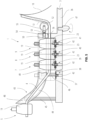
FIG. 5 shows theplatform 3 of thesupply system 1 in more detail. Theplatform 3 comprises an one-pieceelongated part units 5 to 9. For example, floatingunit 7 is stored atconnection point 39, floatingunit 8 is stored atconnection point 40 and floatingunit 9 is stored atconnection point 41 while floatingunit 5 is still floating in the air. Additional connection points may be integrated in theplatform 3 betweenconnection point 38 andconnection point 39 for additional floating units as forexample floating unit 6. To indicate that additional connection points may be available theelongated part FIG. 5 . - Each
connection point 38 to 41 comprises an additionalelectrical interface 59 and an additionalfluidic interface 58 as can be seen inFIG. 6 andFIG. 7 for connecting the firstelectrical interface 29 and the firstfluidic interface 23 of a floating unit positioned at one of the connection points. The firstelectrical interface 29 and the additionalelectrical interface 59 are designed as an inductive electrical interface so that energy may be transferred from one interface to the other even if a gap is between the two interfaces. I. e., the firstelectrical interface 29 and the additionalelectrical interface 59 may be used as an inductive charging interface to charge thebattery 34 of aclamping unit 19. Both interfaces may also be used to transfer signals, e. g. to control theactuator 22 of the clampingunit 19 or to control thebattery 34. - For storing floating
unit 5 at theconnection point 38 analogously to the floatingunit winch 10 is driven to wind up thebendable connection element 4. Thebendable connection element 4 is guided above the connection points 38 to 41 so that each floatingunit 5 to 9 can be pulled to a connection point. Anextension 50 of theplatform 3 comprises aguidance 56 through which thebendable connection element 4 is guided to keep thebendable connection element 4 aligned with the connection points. Thebendable connection element 4 moves freely through each clampingunit 19 of the floatingunits 7 to 9 already stored at theplatform 3 since these clampingunits 19 are in the released state. Instead, clampingunit 19 of the floatingunit 5 is in the fixed state and is pulled by thebendable connection element 4 in direction to theconnection point 38. - As can be seen in
FIG. 5 , the floatingunit 5 approaches arail system 43 of theplatform 3. Therail system 43 is also shown inFIG. 6 in a cross-sectional view. It comprises aleft rail 64 and aright rail 44 for guiding theclamping unit 19 of the floatingunit 5 towards the connection points. The rails are formed of pressed steel metal. Pillars are provided to position the rails relative toplatform 3. As best seen inFIG. 5 , theleft rail 64 is fixed to theplatform 3 by means of aleft pillar 57 and theright rail 44 is fixed to theplatform 3 by means of aright pillar 46 at a first area. Further pillars are indicated withright pillar 45 for connection with theright rail 44 whilepillar 57 and further rails for connection of aleft rail 64 are omitted for clarity reasons. The left andright rails right rails extension 50 of theplatform 3. - Left and
right rails unit 19 of each floatingunit 5 to 9 can slide therebetween. The left and theright rail intermediate portion 49 having afirst profile 63 and a catchingportion 48 having asecond profile 60. The profiles can be seen inFIG. 6 . Theintermediate portion 49 extends horizontally from theextension 50 to thepillars connection point 38. Thus, theintermediate portion 49 provides a correct positioning of the clampingunits 19 at their connection points. - The
intermediate portion 49 then extends into the catchingportion 48 from thepillar 46 to thepillar 45 on the right hand side and from thepillar 57 to another pillar opposite to thepillar 57 on the left hand side. The first andsecond profile units 19. Thefirst profile 63 matches with the tapering 35 of the clampingunits 19 with an offset of about 1 mm prohibiting that any clampingunit 19 of a floating unit may escape upwards. Along the catchingportion 48, thefirst profile 63 extends into asecond profile 60. Thesecond profile 60 is of a similar shape as thefirst profile 63 having a roundedcontour 61 and arounded leg 62 with the major difference that theprofile 60 is widened to enable theclamping unit 19 of the approaching floatingunit 5 to enter therail system 43 even with a slight offset. I. e., the distance between the left andright rail portion 48 than in the area of theintermediate portion 49 so that thesecond profile 60 matches also with the tapering 35 but with a much greater offset than 1 mm. The rotationally symmetric geometry of the clampingunits 19 enables catching and/or centering of the clampingunits 19 within therail system 43 independent of any vertical rotation of the clampingunits 19. Therounded contour 61 of the left andright rail protective sleeve 32 of the floating unit can pass. Theprotective sleeve 32 keeps therope 33 distant ofrail system 43 to avoid that therope 33 is not unintentionally entangled with one of therails - Instead of a fixed connection between the catching
portion 48 and theintermediate portion 49, the catchingportion 48 may be rotatable in a horizontal transvers direction to enable the adaption to different operating height. Thereby it can be prohibited that the catchingportion 48 is catching anenvelope 20 instead of aclamping unit 19 of a floating unit. - While the
winch 10 winds up thebendable connection element 4 the floatingunit 5 is pulled in a horizontal and vertical direction towards theconnection point 38 and theclamping unit 19 of the floatingunit 5 will be caught by the catchingportion 48 of therail system 43. Then, the clampingunit 19 will be guided by therails left rail 64 and theright rail 44 of therail system 43. Thebendable connection element 4 pulls the floatingunit 5 until the floatingunit 5 reaches the next free connection point, hereconnection point 38. The shape of therail system 43 guides the clampingunit 19 of the floatingunit 5 downwards so that the clampingunit 19 of the floatingunit 5 will be aligned with theconnection point 38 of theplatform 3. Thus, the first interface of the clampingunit 19 will be correctly positioned relatively to the additional interface of theconnection point 38. With both the first and the additional interfaces aligned with each other, the connection of the electrical and fluidic interfaces can be provided as explained below so that the firstfluidic interface 23 of the floatingunit 5 will be connected to the additionalfluidic interface 58 of theconnection point 38 and that the firstelectrical interface 29 of the floatingunit 5 will be connected to the additionalelectric interface 59 of theconnection point 38. - When the floating
unit 5 is located at theconnection point 38 similar to the other floatingunits 7 to 9 located at their corresponding connection points 39 to 41 the firstelectrical interface 29 of the floatingunit 5 will be energized by the additionalelectrical interface 59 of theconnection point 38. The electrical energy will then be transferred from the firstelectrical interface 29 to theactuator 22 of the clampingunit 19 of the floatingunit 5 to switch theclamping unit 19 from the fixed state to the released state so that thebendable connection element 4 can also freely pass through the clampingunit 19 of the floatingunit 5 analogously to the other floatingunit 7 to 9 stored at theplatform 3. - When the floating
unit 5 is located at theconnection point 38 theclamping unit 19 of the floatingunit 5 leans against theadjacent clamping unit 19 of the floatingunit 7 and is not able to move further with thebendable connection element 4 winded up by thewinch 10. But there may be a slight time delay between the positioning of the clampingunit 19 of the floatingunit 5 at theconnection point 38 and the switch of clampingunit 19 into released state. I. e., the clampingunit 19 of the floatingunit 5 being still in the fixed state blocks the movement of thebendable connection element 4 during the time delay so that thebendable connection element 4 is tightened and changes its routing as indicated by the dottedbendable connection element 51. Thus, thebendable connection element 4 presses against astrain relief 52 arranged between theextension 50 and thewinch 10 as can be seen inFIG. 5 . Thestrain relief 52 comprising aslider 54 mounted horizontally moveable in theextension 50 and a roller biased by aspring 53 against thebendable connection element 4 is switchable between a tensioned state and a reliefing state. In the tensioned state thespring 53 presses thebendable connection element 4 with the roller towards thewinch 10. In the reliefing state thestrain relief 52 is retracted by thebendable connection element 4 so that the roller changes its position to aroller position 55. The retraction of thestrain relief 52 enables that a short part of thebendable connection element 4 can still be wound up by thewinch 10 until the clampingunit 19 of the floatingunit 5 has switched into the released state. After theclamping unit 19 releases thebendable connection element 4 thespring 53 presses thestrain relief 52 to the position of the tensioned state again. So, thewinch 10 wouldn't be interrupted winding up of thebendable connection element 4 even when a floating unit is positioned at a connection point and thereby blocks the movement of thebendable connection element 4 for a short moment. In addition, a damage caused by the blockedbendable connection element 4 can be prevented. - The floating
unit 5 can be fluidically connected to theconnection point 38 analogously to the other floatingunits 7 to 9 already stored at theplatform 3 when the floatingunit 5 is stored at theplatform 3. The process of fluidically connecting a floating unit to theplatform 3 is for all floatingunits 5 to 9 the same and will be explained now by way of example ofFIG. 6 andFIG. 7 . - The floating unit shown in
FIG. 6 may be any one of the floatingunits 5 to 9 stored at one of the connection points 38 to 41 of theplatform 3.FIG. 7 shows a lower part of the clampingunit 19 in more detail comprising the firstfluidic interface 23 and the firstelectrical interface 29 of the floating unit shown inFIG. 6 as well as the additionalfluidic interface 58 and the additionalelectrical interface 59 of the connection point at which the floating unit ofFIG. 6 is stored at. - The first
fluidic interface 23 is connected with theconduit 24 and comprises thecheck valve 25 including aseat 69 and a closingmember 68 actuatable by avalve spring 67. Thevalve spring 67 biases the closingmember 68 towards theseat 69 to block theconduit 24. In addition, the pressure of the fluid within theenvelope 20 may press the closingmember 68 towards theseat 69. The closingmember 68 is designed as a ball and theseat 69 is inclined so that the ball is pressed against theseat 69 to avoid a leakage and a reverse flow of fluid coming throughcheck valve 25 from theenvelope 20 of the floating unit. - The additional
fluidic interface 58 comprises abore 42 and a sealing 70. The sealing 70 is slideably inserted in thebore 42 and can be moved between a sealing position and a retractedposition 71 as indicated with a dotted line. Thebore 42 is connected to a fluid supply unit comprising a reservoir of fluid for supplying a fluid such as helium. Thecontrol unit 13 may control the fluid supply unit to pump or to draw fluid through thebore 42. - The
interface 16 of thecontrol unit 13 is connected with the additionalelectrical interface 59 and detects when the firstelectrical interface 29 of the clampingunit 19 of the floating unit is connected with the additionalelectrical interface 59 to determine that the floating unit is stored at the connection point in an adequate position for starting the fluid supply process. - When the floating unit is stored at the connection point the first
fluidic interface 23 and the additionalfluidic interface 58 can be sealed with each other so that a leakage free transfer of fluid from one fluidic interface to the other is possible. Then, thecontrol unit 13 controls the fluid supply unit to pump fluid from the reservoir to thebore 42. The fluid in thebore 42 presses against the sealing 70 being in the retractedposition 71 to move the sealing 70 towards the firstfluidic interface 23 of the clampingunit 19 so that the sealing 70 is pressed against a part of the clampingunit 19, here theseat 69. Optionally, the sealing 70 may protrude into the firstfluidic interface 23. Then, the sealing 70 is in the sealing position and prevents a leakage between the firstfluidic interface 23 and the additionalfluidic interface 58. The sealing 70 may be retained by acirclip 72 which engages in a circumferential groove in thebore 42. - The fluid coming from the
bore 42 is transferred from the additionalfluidic interface 58 to the firstfluidic interface 23 and presses against the closingmember 68 of thecheck valve 25. When the pressure within thebore 42 is high enough the fluid compresses thevalve spring 67 and opens thecheck valve 25 so that the fluid is pressed into theconduit 24. The pressure transfers the fluid through theconduit 24 into theenvelope 20 of the floating unit (seeFIG. 6 ). I. e., bore 42,conduit 24 and theenvelope 20 are fluidically connected so that fluid may be added or released for adjusting thegas volume 21 of theenvelope 20. Thecontrol unit 13 may determine the pressure of the fluid to control the amount of fluid to be transferred into theenvelope 20 or released out of theenvelope 20. - When the pressure falls below the spring force of the
valve spring 67 thevalve spring 67 presses the closingmember 68 against theseat 69 for closing thecheck valve 25 again. Additionally, the sealing 70 moves back into the retractedposition 71. - Since the
platform 3 comprises several connection points 38 to 41 as described above multiple floating units stored at theplatform 3 can be supplied with fluid simultaneously (seeFIG. 5 ). Alternatively, instead of having multiple additionalfluidic interfaces 58 to individually supply the floating units with fluid, a single additional fluidic interface may be provided which is configured to move horizontally below each floating unit stored at theplatform 3. In addition, such an additional fluidic interface may also be configured to move upwards for enabling a sealing contact to aclamping unit 19 prior to supply. Electric supply may also provided in that manner. - The
platform 3 is designed for a very compact storage of the floatingunits 5 to 9 since the distance from one connection point to another is adapted to the size of the clampingunits 19. As can be seen inFIG. 5 the clampingunits 19 can be stored without any gap between one and another clampingunit 19 at theplatform 3. Since theenvelopes 20 of the floating units are of a greater size than the clampingunits 19 theenvelopes 20 of each stored floating unit may swerve to a left hand position indicated by dottedline 65 or to a right hand position indicated by dotted line 66 (seeFIG. 6 ) when multiple floating units are stored at the platform 3 (seeFIG. 5 ). - All references cited herein are incorporated herein in their entireties. If there is a conflict between definitions herein and in an incorporated reference, the definition herein shall control.
-
- 1 supply system
- 2 vehicle
- 3 platform
- 4 bendable connection element
- 5 floating unit
- 6 floating unit
- 7 floating unit
- 8 floating unit
- 9 floating unit
- 10 winch
- 11 agricultural vehicle
- 12 sensor
- 13 control unit
- 14 obstacle
- 15 height
- 16 interface
- 17 controller
- 18 memory
- 19 clamping unit
- 20 envelope
- 21 gas volume
- 22 actuator
- 23 first fluidic interface
- 24 conduit
- 25 check valve
- 26 piston
- 27 spring
- 28 solenoid
- 29 first electrical interface
- 30 line
- 31 line
- 32 sleeve
- 33 rope
- 34 battery
- 35 tapering
- 36 part
- 37 part
- 38 connection point
- 39 connection point
- 40 connection point
- 41 connection point
- 42 bore
- 43 rail system
- 44 right rail
- 45 right pillar
- 46 right pillar
- 47 base body
- 48 catching portion
- 49 intermediate portion
- 50 extension
- 51 routing
- 52 strain relief
- 53 spring
- 54 slider
- 55 roller position
- 56 guidance
- 57 left pillar
- 58 additional fluidic interface
- 59 additional electrical interface
- 60 profile
- 61 rounded contour
- 62 rounded leg
- 63 profile
- 64 left rail
- 65 item
- 66 item
- 67 valve spring
- 68 closing member
- 69 seat
- 70 sealing
- 71 retracted position
- 72 circlip
Claims (15)
- A floating unit (5, 6, 7, 8, 9) for lifting a bendable connection element (4) comprisinga clamping unit (19) switchable between a fixed state for attaching the floating unit (5, 6, 7, 8, 9) to the bendable connection element (4) and a released state for detaching the floating unit (5, 6, 7, 8, 9) from the bendable connection element (4);an envelope (20) for enclosing a gas volume (21);wherein the clamping unit (19) comprises
a first interface; - The floating unit (5, 6, 7, 8, 9) of claim 1, comprisinga conduit (24);wherein the first interface comprises a first fluidic interface (23); andthe conduit (24) is connected with the first fluidic interface (23) and the envelope (20) for supplying the gas volume (21) with a fluid.
- The floating unit (5, 6, 7, 8, 9) of claim 2, wherein the first fluidic interface (23) comprises
a check valve (25) comprising a seat (12) and a closing member (68) being moveable towards the seat (12) for sealing the seat (12). - The floating unit (5, 6, 7, 8, 9) of claim 3, the check valve (25) comprising a valve spring (67) for biasing the closing member (68) towards the seat (69).
- The floating unit (5, 6, 7, 8, 9) of any one of claims 1 to 4, wherein the first interface comprises a first electrical interface (29); and
the clamping unit (19) comprises an actuator (22) connected with first electrical interface (29) for supplying the actuator (22) with electrical energy. - The floating unit (5, 6, 7, 8, 9) of claim 5, wherein the actuator (22) is configured to switch the clamping unit (19) into the released state when the actuator (22) is energized with electrical energy and to switch the clamping unit (19) into the fixed state when the actuator (22) is deenergized.
- A supply system (1) for a floating unit (5, 6, 7, 8, 9) comprisingat least one floating unit (5, 6, 7, 8, 9) of any one of claims 1 to 6;a bendable connection element (4); anda platform (3) comprisingat least one connection point (38, 39, 40, 41) for the at least one floating unit (5, 6, 7, 8, 9);the at least one connection point (38, 39, 40, 41) comprising an additional interface for connecting the first interface of the at least one floating unit (5, 6, 7, 8, 9) when the clamping unit (19) of the at least one floating unit (5, 6, 7, 8, 9) is aligned with the at least one connection point (38, 39, 40, 41);wherein the bendable connection element (4) is threaded through the clamping unit (19) of the at least one floating unit (5, 6, 7, 8, 9).
- The supply system (1) of claim 7, whereinthe additional interface comprises an additional fluidic interface (58); andthe at least one additional fluidic interface (58) comprises a bore (42) and a sealing (70) being moveable along the bore (42) between a retracted position (71) and a sealing position.
- The supply system (1) of claim 8, whereinthe at least one floating unit (5, 6, 7, 8, 9) is placed at the at least one connection point (38, 39, 40, 41); andthe sealing (69) moved in the sealing position is protruding into the first fluidic interface (23) of the floating unit (5, 6, 7, 8, 9).
- The supply system (1) of any one of claims 7 to 9, the additional interface comprising at least one additional electrical interface (59) for connecting the first electrical interface (29) of the at least one floating unit (5, 6, 7, 8, 9).
- The supply system (1) of claim 10, wherein the at least one additional electrical interface (59) is energized with electrical energy when the first electrical interface (29) of the at least one floating unit (5, 6, 7, 8, 9) is connected with the at least one additional electrical interface (59).
- The supply system (1) of any one of claims 7 to 11, comprising a winch (10) for winding up the bendable connection element (4); and
the platform (3) comprising a strain relief (52) being in contact with the bendable connection element (4) the strain relief (52) being switchable between a reliefing state and a tensioned state; wherein the strain relief (52) switches into the reliefing state when the at least one floating unit (5, 6, 7, 8, 9) is positioned at the at least one connection point (38, 39, 40, 41) and the clamping unit (19) of the at least one floating unit (5, 6, 7, 8, 9) is attached to the bendable connection element (4) being wound up by the winch (10). - The supply system (1) of any one of claims 7 to 12, comprising a rail (44, 64) for guiding the clamping unit (19) of the at least one floating unit (5, 6, 7, 8, 9) towards the at least one connection point (38, 39, 40, 41).
- The supply system (1) of any one of claims 7 to 13, comprising a guidance (56) for guiding the bendable connection element (4) in alignment with the at least one connection point (38, 39, 40, 41).
- The supply system (1) of any one of claims 7 to 14, comprising more than one connection point (38, 39, 40, 41); wherein a distance between two connection points (38, 39, 40, 41) is adapted for a gapless positioning of the clamping units (19) at the connection points (38, 39, 40, 41) next to each other.
Applications Claiming Priority (1)
| Application Number | Priority Date | Filing Date | Title |
|---|---|---|---|
| GBGB2205519.8A GB202205519D0 (en) | 2022-04-13 | 2022-04-13 | Floating unit for lifting a bendable connection element and supply system for a floating unit |
Publications (2)
| Publication Number | Publication Date |
|---|---|
| EP4261128A1 true EP4261128A1 (en) | 2023-10-18 |
| EP4261128B1 EP4261128B1 (en) | 2025-08-27 |
Family
ID=81653113
Family Applications (1)
| Application Number | Title | Priority Date | Filing Date |
|---|---|---|---|
| EP23162581.5A Active EP4261128B1 (en) | 2022-04-13 | 2023-03-17 | Floating unit for lifting a bendable connection element and supply system for a floating unit |
Country Status (3)
| Country | Link |
|---|---|
| US (1) | US12415595B2 (en) |
| EP (1) | EP4261128B1 (en) |
| GB (1) | GB202205519D0 (en) |
Cited By (1)
| Publication number | Priority date | Publication date | Assignee | Title |
|---|---|---|---|---|
| KR102841976B1 (en) * | 2024-12-10 | 2025-08-04 | 주식회사 아쎄따 | Unmanned Aerial Vehicle for Collecting Trash Balloons from Airborne and Its Operation Method |
Families Citing this family (2)
| Publication number | Priority date | Publication date | Assignee | Title |
|---|---|---|---|---|
| GB202205518D0 (en) * | 2022-04-13 | 2022-05-25 | Agco Int Gmbh | Supply system for a vehicle connected to a platform |
| US12595083B1 (en) * | 2024-11-20 | 2026-04-07 | Blue Vigil Llc | Drone base |
Citations (5)
| Publication number | Priority date | Publication date | Assignee | Title |
|---|---|---|---|---|
| EP2774838A2 (en) * | 2013-03-08 | 2014-09-10 | The Boeing Company | Autonomous aircraft |
| US20170043872A1 (en) * | 2014-07-08 | 2017-02-16 | Todd Michael Whitaker | Tethered unmanned aerial vehicle fire fighting system |
| DE102016202627A1 (en) | 2016-02-19 | 2017-08-24 | Deere & Company | Aircraft arrangement for sensory investigation and / or monitoring of agricultural areas and / or operations |
| US20220023685A1 (en) * | 2019-02-20 | 2022-01-27 | Ebara Corporation | Drone system |
| US11235890B1 (en) * | 2016-10-25 | 2022-02-01 | Working Drones, Inc. | Unmanned aerial vehicle having an elevated surface sensor |
Family Cites Families (10)
| Publication number | Priority date | Publication date | Assignee | Title |
|---|---|---|---|---|
| US3216466A (en) * | 1961-09-20 | 1965-11-09 | Litton Systems Inc | Pressure actuated release mechanism |
| DE2854093C2 (en) * | 1978-12-14 | 1981-01-22 | Emil 8100 Garmisch-Partenkirchen Schmidt | Marking device for position indication |
| US7708222B2 (en) * | 2007-04-27 | 2010-05-04 | Stratocomm Corporation | Long mission tethered aerostat and method of accomplishing |
| US20140012433A1 (en) * | 2012-05-08 | 2014-01-09 | World Surveillance Group, Inc. | Self-powered releasable aerostat and method and system for releasing and controlling the aerostat |
| US9852644B2 (en) | 2013-03-24 | 2017-12-26 | Bee Robotics Corporation | Hybrid airship-drone farm robot system for crop dusting, planting, fertilizing and other field jobs |
| US9387928B1 (en) * | 2014-12-18 | 2016-07-12 | Amazon Technologies, Inc. | Multi-use UAV docking station systems and methods |
| GB2557857B (en) * | 2015-10-27 | 2020-11-04 | Walmart Apollo Llc | Method and apparatus for an airborne drone training track |
| JP6867924B2 (en) * | 2017-10-05 | 2021-05-12 | 本田技研工業株式会社 | Aerial sprayer, unmanned aerial vehicle system and unmanned aerial vehicle |
| DE102018113742A1 (en) | 2018-06-08 | 2019-12-12 | Claas Selbstfahrende Erntemaschinen Gmbh | Agricultural work system |
| WO2022145331A1 (en) * | 2020-12-29 | 2022-07-07 | 株式会社クボタ | Agricultural machine |
-
2022
- 2022-04-13 GB GBGB2205519.8A patent/GB202205519D0/en not_active Ceased
-
2023
- 2023-03-16 US US18/185,144 patent/US12415595B2/en active Active
- 2023-03-17 EP EP23162581.5A patent/EP4261128B1/en active Active
Patent Citations (5)
| Publication number | Priority date | Publication date | Assignee | Title |
|---|---|---|---|---|
| EP2774838A2 (en) * | 2013-03-08 | 2014-09-10 | The Boeing Company | Autonomous aircraft |
| US20170043872A1 (en) * | 2014-07-08 | 2017-02-16 | Todd Michael Whitaker | Tethered unmanned aerial vehicle fire fighting system |
| DE102016202627A1 (en) | 2016-02-19 | 2017-08-24 | Deere & Company | Aircraft arrangement for sensory investigation and / or monitoring of agricultural areas and / or operations |
| US11235890B1 (en) * | 2016-10-25 | 2022-02-01 | Working Drones, Inc. | Unmanned aerial vehicle having an elevated surface sensor |
| US20220023685A1 (en) * | 2019-02-20 | 2022-01-27 | Ebara Corporation | Drone system |
Cited By (1)
| Publication number | Priority date | Publication date | Assignee | Title |
|---|---|---|---|---|
| KR102841976B1 (en) * | 2024-12-10 | 2025-08-04 | 주식회사 아쎄따 | Unmanned Aerial Vehicle for Collecting Trash Balloons from Airborne and Its Operation Method |
Also Published As
| Publication number | Publication date |
|---|---|
| EP4261128B1 (en) | 2025-08-27 |
| US20230331366A1 (en) | 2023-10-19 |
| GB202205519D0 (en) | 2022-05-25 |
| US12415595B2 (en) | 2025-09-16 |
Similar Documents
| Publication | Publication Date | Title |
|---|---|---|
| US12415595B2 (en) | Floating unit for lifting a bendable connection element and supply system for a floating unit | |
| US12235066B2 (en) | Autonomous transport-based unmanned ammunition loading system for stationary guns and automatic loading device constituting same | |
| EP4261129A1 (en) | Supply system for a vehicle connected to a platform | |
| US8336479B2 (en) | Systems and methods of use for submerged deployment of objects | |
| CN106884820B (en) | A kind of storage winch hydraulic system | |
| CN110271891A (en) | A kind of unmanned electrode piece loading device and system | |
| KR101020006B1 (en) | Mechanically Controlled Fluid Injection System | |
| US20190136874A1 (en) | Electro-hydraulic work vehicle with energy recovery | |
| CN205207303U (en) | Store up cable winch hydraulic system | |
| JP5826948B2 (en) | Thruster system and ship including the same | |
| US10044089B2 (en) | Underwater antenna device with a non-stationary antenna and underwater vessel | |
| CN112896471B (en) | Multifunctional suspended underwater robot and base station system thereof | |
| CN108278232A (en) | A kind of passive heave compensation system of hydraulic cylinder type based on hydraulic transformer | |
| CN109973448B (en) | Towing winch hydraulic system with multiple working modes | |
| CN212482287U (en) | Rocket Connector Guard | |
| CN204150975U (en) | Secondary motor control wave compensation system | |
| US4114827A (en) | Cable reel valve and system | |
| SE1450548A1 (en) | Female docking device | |
| CN110886734B (en) | Flow valve and position control method and device thereof | |
| NO336260B1 (en) | Apparatus for controlling a deflector and an actuator for use in the apparatus | |
| CN220996677U (en) | Boarding bridge | |
| US5377164A (en) | Method to operate with a wire-guided, in air or water, movable vehicle and a device for carrying out the method | |
| ITMI990930A1 (en) | HYDRAULIC DRIVE SYSTEMS PARTICULARLY FOR AUTOMATIC OR SEMI-AUTOMATIC TRANSMISSIONS | |
| JP6141749B2 (en) | Underwater lifting device | |
| CN208381447U (en) | A kind of bi-bit bi-pass normally closed solenoid valve with buffer structure |
Legal Events
| Date | Code | Title | Description |
|---|---|---|---|
| PUAI | Public reference made under article 153(3) epc to a published international application that has entered the european phase |
Free format text: ORIGINAL CODE: 0009012 |
|
| STAA | Information on the status of an ep patent application or granted ep patent |
Free format text: STATUS: THE APPLICATION HAS BEEN PUBLISHED |
|
| AK | Designated contracting states |
Kind code of ref document: A1 Designated state(s): AL AT BE BG CH CY CZ DE DK EE ES FI FR GB GR HR HU IE IS IT LI LT LU LV MC ME MK MT NL NO PL PT RO RS SE SI SK SM TR |
|
| STAA | Information on the status of an ep patent application or granted ep patent |
Free format text: STATUS: REQUEST FOR EXAMINATION WAS MADE |
|
| 17P | Request for examination filed |
Effective date: 20240418 |
|
| RBV | Designated contracting states (corrected) |
Designated state(s): AL AT BE BG CH CY CZ DE DK EE ES FI FR GB GR HR HU IE IS IT LI LT LU LV MC ME MK MT NL NO PL PT RO RS SE SI SK SM TR |
|
| GRAP | Despatch of communication of intention to grant a patent |
Free format text: ORIGINAL CODE: EPIDOSNIGR1 |
|
| STAA | Information on the status of an ep patent application or granted ep patent |
Free format text: STATUS: GRANT OF PATENT IS INTENDED |
|
| RIC1 | Information provided on ipc code assigned before grant |
Ipc: B25B 5/00 20060101ALN20250331BHEP Ipc: B66D 1/00 20060101ALN20250331BHEP Ipc: B64U 101/45 20230101ALN20250331BHEP Ipc: B64U 101/40 20230101ALN20250331BHEP Ipc: B64U 70/93 20230101ALI20250331BHEP Ipc: B64U 10/30 20230101ALI20250331BHEP Ipc: B64U 10/60 20230101ALI20250331BHEP Ipc: B64C 39/02 20230101AFI20250331BHEP |
|
| INTG | Intention to grant announced |
Effective date: 20250416 |
|
| GRAS | Grant fee paid |
Free format text: ORIGINAL CODE: EPIDOSNIGR3 |
|
| GRAA | (expected) grant |
Free format text: ORIGINAL CODE: 0009210 |
|
| STAA | Information on the status of an ep patent application or granted ep patent |
Free format text: STATUS: THE PATENT HAS BEEN GRANTED |
|
| AK | Designated contracting states |
Kind code of ref document: B1 Designated state(s): AL AT BE BG CH CY CZ DE DK EE ES FI FR GB GR HR HU IE IS IT LI LT LU LV MC ME MK MT NL NO PL PT RO RS SE SI SK SM TR |
|
| REG | Reference to a national code |
Ref country code: CH Ref legal event code: EP |
|
| REG | Reference to a national code |
Ref country code: DE Ref legal event code: R096 Ref document number: 602023005984 Country of ref document: DE |
|
| REG | Reference to a national code |
Ref country code: IE Ref legal event code: FG4D |
|
| REG | Reference to a national code |
Ref country code: NL Ref legal event code: MP Effective date: 20250827 |
|
| PG25 | Lapsed in a contracting state [announced via postgrant information from national office to epo] |
Ref country code: IS Free format text: LAPSE BECAUSE OF FAILURE TO SUBMIT A TRANSLATION OF THE DESCRIPTION OR TO PAY THE FEE WITHIN THE PRESCRIBED TIME-LIMIT Effective date: 20251227 |
|
| PG25 | Lapsed in a contracting state [announced via postgrant information from national office to epo] |
Ref country code: NO Free format text: LAPSE BECAUSE OF FAILURE TO SUBMIT A TRANSLATION OF THE DESCRIPTION OR TO PAY THE FEE WITHIN THE PRESCRIBED TIME-LIMIT Effective date: 20251127 |
|
| REG | Reference to a national code |
Ref country code: LT Ref legal event code: MG9D |
|
| PG25 | Lapsed in a contracting state [announced via postgrant information from national office to epo] |
Ref country code: PT Free format text: LAPSE BECAUSE OF FAILURE TO SUBMIT A TRANSLATION OF THE DESCRIPTION OR TO PAY THE FEE WITHIN THE PRESCRIBED TIME-LIMIT Effective date: 20251229 |
|
| PG25 | Lapsed in a contracting state [announced via postgrant information from national office to epo] |
Ref country code: FI Free format text: LAPSE BECAUSE OF FAILURE TO SUBMIT A TRANSLATION OF THE DESCRIPTION OR TO PAY THE FEE WITHIN THE PRESCRIBED TIME-LIMIT Effective date: 20250827 |
|
| PG25 | Lapsed in a contracting state [announced via postgrant information from national office to epo] |
Ref country code: HR Free format text: LAPSE BECAUSE OF FAILURE TO SUBMIT A TRANSLATION OF THE DESCRIPTION OR TO PAY THE FEE WITHIN THE PRESCRIBED TIME-LIMIT Effective date: 20250827 Ref country code: NL Free format text: LAPSE BECAUSE OF FAILURE TO SUBMIT A TRANSLATION OF THE DESCRIPTION OR TO PAY THE FEE WITHIN THE PRESCRIBED TIME-LIMIT Effective date: 20250827 |
|
| PG25 | Lapsed in a contracting state [announced via postgrant information from national office to epo] |
Ref country code: GR Free format text: LAPSE BECAUSE OF FAILURE TO SUBMIT A TRANSLATION OF THE DESCRIPTION OR TO PAY THE FEE WITHIN THE PRESCRIBED TIME-LIMIT Effective date: 20251128 |
|
| PG25 | Lapsed in a contracting state [announced via postgrant information from national office to epo] |
Ref country code: SE Free format text: LAPSE BECAUSE OF FAILURE TO SUBMIT A TRANSLATION OF THE DESCRIPTION OR TO PAY THE FEE WITHIN THE PRESCRIBED TIME-LIMIT Effective date: 20250827 |
|
| PG25 | Lapsed in a contracting state [announced via postgrant information from national office to epo] |
Ref country code: LV Free format text: LAPSE BECAUSE OF FAILURE TO SUBMIT A TRANSLATION OF THE DESCRIPTION OR TO PAY THE FEE WITHIN THE PRESCRIBED TIME-LIMIT Effective date: 20250827 |
|
| PG25 | Lapsed in a contracting state [announced via postgrant information from national office to epo] |
Ref country code: PL Free format text: LAPSE BECAUSE OF FAILURE TO SUBMIT A TRANSLATION OF THE DESCRIPTION OR TO PAY THE FEE WITHIN THE PRESCRIBED TIME-LIMIT Effective date: 20250827 Ref country code: BG Free format text: LAPSE BECAUSE OF FAILURE TO SUBMIT A TRANSLATION OF THE DESCRIPTION OR TO PAY THE FEE WITHIN THE PRESCRIBED TIME-LIMIT Effective date: 20250827 |
|
| PG25 | Lapsed in a contracting state [announced via postgrant information from national office to epo] |
Ref country code: RS Free format text: LAPSE BECAUSE OF FAILURE TO SUBMIT A TRANSLATION OF THE DESCRIPTION OR TO PAY THE FEE WITHIN THE PRESCRIBED TIME-LIMIT Effective date: 20251127 |
|
| PG25 | Lapsed in a contracting state [announced via postgrant information from national office to epo] |
Ref country code: ES Free format text: LAPSE BECAUSE OF FAILURE TO SUBMIT A TRANSLATION OF THE DESCRIPTION OR TO PAY THE FEE WITHIN THE PRESCRIBED TIME-LIMIT Effective date: 20250827 |
|
| REG | Reference to a national code |
Ref country code: AT Ref legal event code: MK05 Ref document number: 1829746 Country of ref document: AT Kind code of ref document: T Effective date: 20250827 |
|
| PG25 | Lapsed in a contracting state [announced via postgrant information from national office to epo] |
Ref country code: SM Free format text: LAPSE BECAUSE OF FAILURE TO SUBMIT A TRANSLATION OF THE DESCRIPTION OR TO PAY THE FEE WITHIN THE PRESCRIBED TIME-LIMIT Effective date: 20250827 |
|
| PG25 | Lapsed in a contracting state [announced via postgrant information from national office to epo] |
Ref country code: DK Free format text: LAPSE BECAUSE OF FAILURE TO SUBMIT A TRANSLATION OF THE DESCRIPTION OR TO PAY THE FEE WITHIN THE PRESCRIBED TIME-LIMIT Effective date: 20250827 |
|
| PGFP | Annual fee paid to national office [announced via postgrant information from national office to epo] |
Ref country code: DE Payment date: 20260319 Year of fee payment: 4 |
|
| PG25 | Lapsed in a contracting state [announced via postgrant information from national office to epo] |
Ref country code: AT Free format text: LAPSE BECAUSE OF FAILURE TO SUBMIT A TRANSLATION OF THE DESCRIPTION OR TO PAY THE FEE WITHIN THE PRESCRIBED TIME-LIMIT Effective date: 20250827 |
|
| PG25 | Lapsed in a contracting state [announced via postgrant information from national office to epo] |
Ref country code: IT Free format text: LAPSE BECAUSE OF FAILURE TO SUBMIT A TRANSLATION OF THE DESCRIPTION OR TO PAY THE FEE WITHIN THE PRESCRIBED TIME-LIMIT Effective date: 20250827 |
|
| PGFP | Annual fee paid to national office [announced via postgrant information from national office to epo] |
Ref country code: FR Payment date: 20260323 Year of fee payment: 4 |
|
| PG25 | Lapsed in a contracting state [announced via postgrant information from national office to epo] |
Ref country code: CZ Free format text: LAPSE BECAUSE OF FAILURE TO SUBMIT A TRANSLATION OF THE DESCRIPTION OR TO PAY THE FEE WITHIN THE PRESCRIBED TIME-LIMIT Effective date: 20250827 |
|
| PG25 | Lapsed in a contracting state [announced via postgrant information from national office to epo] |
Ref country code: EE Free format text: LAPSE BECAUSE OF FAILURE TO SUBMIT A TRANSLATION OF THE DESCRIPTION OR TO PAY THE FEE WITHIN THE PRESCRIBED TIME-LIMIT Effective date: 20250827 Ref country code: SK Free format text: LAPSE BECAUSE OF FAILURE TO SUBMIT A TRANSLATION OF THE DESCRIPTION OR TO PAY THE FEE WITHIN THE PRESCRIBED TIME-LIMIT Effective date: 20250827 |