EP4261122A1 - Marine drives having steerable gearcase - Google Patents
Marine drives having steerable gearcase Download PDFInfo
- Publication number
- EP4261122A1 EP4261122A1 EP23164754.6A EP23164754A EP4261122A1 EP 4261122 A1 EP4261122 A1 EP 4261122A1 EP 23164754 A EP23164754 A EP 23164754A EP 4261122 A1 EP4261122 A1 EP 4261122A1
- Authority
- EP
- European Patent Office
- Prior art keywords
- gearcase
- housing
- driveshaft
- steering
- electric motor
- Prior art date
- Legal status (The legal status is an assumption and is not a legal conclusion. Google has not performed a legal analysis and makes no representation as to the accuracy of the status listed.)
- Pending
Links
Images











Classifications
-
- B—PERFORMING OPERATIONS; TRANSPORTING
- B63—SHIPS OR OTHER WATERBORNE VESSELS; RELATED EQUIPMENT
- B63H—MARINE PROPULSION OR STEERING
- B63H20/00—Outboard propulsion units, e.g. outboard motors or Z-drives; Arrangements thereof on vessels
- B63H20/08—Means enabling movement of the position of the propulsion element, e.g. for trim, tilt or steering; Control of trim or tilt
-
- B—PERFORMING OPERATIONS; TRANSPORTING
- B63—SHIPS OR OTHER WATERBORNE VESSELS; RELATED EQUIPMENT
- B63H—MARINE PROPULSION OR STEERING
- B63H20/00—Outboard propulsion units, e.g. outboard motors or Z-drives; Arrangements thereof on vessels
- B63H20/14—Transmission between propulsion power unit and propulsion element
- B63H20/22—Transmission between propulsion power unit and propulsion element allowing movement of the propulsion element about at least a horizontal axis without disconnection of the drive, e.g. using universal joints
Definitions
- the present disclosure relates to marine drives, and in particular marine drives having a hydraulically actuated steerable gearcase, and stern drives having a powerhead for propulsion, such as an electric motor.
- U.S. Pat. No. 10,800,502 discloses an outboard motor having a powerhead that causes rotation of a driveshaft, a steering housing located below the powerhead, wherein the driveshaft extends from the powerhead into the steering housing, and a lower gearcase located below the steering housing and supporting a propeller shaft that is coupled to the driveshaft so that rotation of the driveshaft causes rotation of the propeller shaft.
- the lower gearcase is steerable about a steering axis with respect to the steering housing and powerhead.
- a stern drive is for a marine vessel.
- the stern drive may comprise a powerhead, a drive assembly configured to support a propulsor for generating a thrust force in water, the propulsor being powered by the powerhead, wherein the drive assembly comprises a driveshaft housing and a gearcase suspended from the driveshaft housing, the gearcase being steerable relative to the driveshaft housing, and a steering actuator configured to steer the gearcase relative to the driveshaft housing.
- the powerhead comprises an electric motor.
- the steering actuator may comprise an electric motor and the electric motor may be located in the driveshaft housing.
- the electric motor and the gearcase may be operably engaged via a gearset.
- the gearset may comprise a pinion and a ring gear.
- the gearset may comprise a worm gear and a ring gear.
- the worm gear may be engaged with the ring gear via teeth having a lead angle which causes the worm gear to resist rotation of the ring gear when the gearcase is subjected to an external force.
- the steering actuator may comprise a first electric motor operably coupled to the gearcase by a first gearset and a second electric motor operably coupled to the gearcase by a second gearset.
- the first electric motor and the second electric motor may be independently operable to steer the gearcase.
- the first electric motor and the second electric motor may operate a common output shaft.
- the gearcase may comprise a steering housing which extends into the driveshaft housing.
- the steering actuator may comprise a rack on the gearcase and a kingpin on the steering housing, wherein movement of the rack rotates the kingpin and thereby steers the gearcase relative to the driveshaft housing.
- the steering actuator may further comprise a cylinder containing the rack, wherein the rack is movable back and forth in the cylinder and thereby steers the gearcase relative to the driveshaft housing.
- a hydraulic pump may be configured to supply hydraulic fluid to the cylinder which moves the rack back and forth in the cylinder and thereby steers the gearcase relative to the driveshaft housing.
- an electric motor may be configured to move the rack back and forth in the cylinder and thereby steer the gearcase relative to the driveshaft housing.
- the electric motor may rotate an output shaft coupled to the rack such that rotation of the output shaft in a first direction causes movement of the rack in a first direction relative to the kingpin and such that rotation of the output shaft in an opposite, second direction causes movement of the rack in an opposite, second direction.
- the output shaft may be coupled to the rack by a ball screw or a roller screw.
- the stern drive may further comprise the propulsor and a driveshaft which operably couples the powerhead to the propulsor, wherein the driveshaft extends through the steering housing and is operably engaged with an output shaft supporting the propulsor.
- An angle gearset may be located in the gearcase, the angle gearset coupling the driveshaft to the output shaft so that rotation of the driveshaft causes rotation of the output shaft.
- Upper and lower bearings may facilitate steering of the steering housing relative to the driveshaft housing.
- a marine drive is for propelling a marine vessel.
- the marine drive includes a drive assembly configured to support a propulsor for generating a thrust force in water, the drive assembly including a driveshaft housing and a gearcase suspended from the driveshaft housing, wherein the drive assembly is trimmable relative to the marine vessel about a trim joint.
- a steering actuator is configured to steer the gearcase relative to the driveshaft housing, and a pump is configured to pump a hydraulic fluid to and/or from the steering actuator via the trim joint.
- the marine drive may comprise a mounting assembly configured to couple the driveshaft housing to the marine vessel.
- the hydraulic fluid may be conveyed through the mounting assembly and through the driveshaft housing.
- the marine drive may include at least one mounting arm which pivotally couples the mounting assembly to the driveshaft housing, wherein the hydraulic fluid is conveyed through the at least one mounting arm.
- the at least one mounting arm may be one of a port mounting arm and a starboard mounting arm, wherein the hydraulic fluid is conveyed through the port mounting arm and through the starboard mounting arm.
- the port mounting arm and the starboard mounting arm may extend from a first one of the driveshaft housing and the mounting assembly and are coupled to a second one of the driveshaft housing and the mounting assembly along the trim joint.
- the trim joint may pivotably couple a stationary member and a rotary member, wherein the hydraulic fluid is conveyed through the stationary member and through the rotary member.
- the stationary member is on the mounting assembly and the rotary member is on the driveshaft housing.
- the marine drive may include a first fluid passage in the stationary member, a second fluid passage in the rotary member, and a chamber in the trim joint which fluidly couples the first fluid passage and the second fluid passage.
- the marine drive may include a third fluid passage which is fluidly coupled to the second fluid passage in the rotary member, wherein the third passage extends from the rotary member to the steering actuator.
- the rotary member may include a stem which is rotatable within a cavity in the stationary member, the stem having at least one radial bore which is fluidly coupled to an annular passage which is fluidly coupled to the second fluid passage.
- the marine drive may include at least one seal which seals an outer diameter surface of the stem to an inner diameter surface of the cavity.
- the steering actuator may comprise a hydraulic cylinder.
- the gearcase may include a steering housing which extends into the driveshaft housing, wherein the steering actuator comprises a rack on the gearcase and a kingpin on the steering housing, and wherein movement of the rack rotates the kingpin and thereby steers the gearcase relative to the driveshaft housing.
- the steering actuator may include a cylinder containing the rack, the rack being movable back and forth in the cylinder to steer the gearcase relative to the driveshaft housing.
- a marine drive is for propelling a marine vessel.
- the marine drive includes a drive assembly configured to support a propulsor for generating a thrust force in water, the drive assembly comprising a driveshaft housing and a gearcase suspended from the driveshaft housing.
- a mounting assembly is configured to couple the driveshaft housing to the marine vessel along a trim joint, wherein the drive assembly is trimmable relative to the mounting assembly about the trim joint.
- a steering actuator is configured to steer the gearcase relative to the driveshaft housing; and a pump is configured to pump a hydraulic fluid to and/or from the steering actuator via the trim joint.
- the hydraulic fluid may be conveyed through the mounting assembly and through the driveshaft housing.
- the trim joint may pivotably couple a stationary member and a rotary member, wherein the hydraulic fluid is conveyed through the stationary member and through the rotary member.
- a marine drive is for propelling a marine vessel.
- the marine drive includes a drive assembly configured to support a propulsor for generating a thrust force in water, the drive assembly comprising a driveshaft housing and a gearcase suspended from the driveshaft housing.
- a mounting assembly is configured to couple the driveshaft housing to the marine vessel along a trim joint, wherein the drive assembly is trimmable relative to the mounting assembly about the trim joint.
- a steering actuator is configured to steer the gearcase relative to the driveshaft housing.
- a pump is configured to pump a hydraulic fluid to and/or from the steering actuator via passages which are entirely contained within the drive assembly and mounting assembly.
- the pump may be mounted on an opposite side of the mounting assembly relative to the drive assembly such that the pump is located in the marine vessel and the drive assembly is located outside of the marine vessel.
- the passages may include a first passage through the mounting assembly and a second passage through the drive assembly.
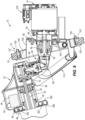
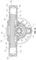
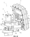
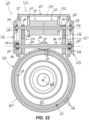
- the present disclosure includes the following figures.
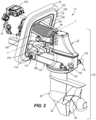
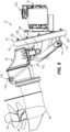
- Figs. 1-8 illustrate a stern drive 12 for propelling a marine vessel in a body of water.
- the stern drive 12 has a powerhead, which in the illustrated example is an electric motor 14, a mounting assembly 16 which affixes the electric motor 14 to and suspends the electric motor 14 from the transom 18 of the marine vessel, and a drive assembly 20 coupled to the mounting assembly 16 and suspended therefrom.
- the illustrated powerhead is not limiting and in other examples the powerhead may include an engine and/or a combination of an engine and an electric motor, and/or any other suitable means for powering a marine drive.
- the mounting assembly 16 is configured so that the powerhead which in the illustrated example is an electric motor 14 is suspended (i.e., cantilevered) from the interior of the transom 18, above the hull of the marine vessel.
- the drive assembly 20 is trimmable up and down relative to the mounting assembly 16, including in non-limiting examples wherein a majority or an entirety of the drive assembly 20 is raised completely out of the water.
- the drive assembly 20 has a driveshaft housing 22 containing a driveshaft 24 and a gearcase 26 containing one or more output shaft(s) 28, e.g., one or more propulsor shaft(s).
- the output shaft(s) 28 extends from the rear of the gearcase 26 and support one or more propulsor(s) 30 configured to generate thrust in the water for propelling the marine vessel.
- the output shaft(s) 28 extend generally transversely to the driveshaft 24.
- propulsor(s) 30 include two counter-rotating propellers.
- the propulsor(s) 30 include one or more impellers and/or any other mechanism for generating a propulsive force in the water.
- the gearcase 26 is steerable about a steering axis S relative to the driveshaft housing 22.
- the gearcase 26 has a steering housing 32 which extends upwardly into the driveshaft housing 22, as well as a torpedo housing 34 which depends from the steering housing 32.
- An angle gearset 36 in the torpedo housing 34 operably couples the lower end of the driveshaft 24 to the output shaft(s) 28 so that rotation of the driveshaft 24 causes rotation of the output shaft(s) 28, which in turn causes rotation of the propulsor(s) 30.
- upper and lower bearings 38, 40 are disposed radially between the steering housing 32 and the driveshaft housing 22.
- the upper and lower bearings 38, 40 rotatably support the steering housing 32 relative to the driveshaft housing 22.
- a steering actuator 42 is configured to cause rotation of the gearcase 26 relative to the driveshaft housing 22.
- the steering actuator 42 is an electric motor 44 located in the driveshaft housing 22 and may be operatively engaged with the gearcase 26 via a gearset.
- the electric motor 44 has an output gear 46 (i.e., a pinion) which is meshed with a ring gear 48 on the steering housing 32 so that rotation of the output gear 46 causes rotation of the gearcase 26 about the steering axis S.
- operation of the electric motor 44 can be controlled via a conventional user input device located at the helm of the marine vessel or elsewhere, which facilitates control of the steering angle of the gearcase 26 and associated propulsor(s) 30. This facilitates steering control of the marine vessel.
- the type and configuration of the steering actuator 42 can vary from what is shown and in other examples could include one or more hydraulic actuators, electro-hydraulic actuators, and/or any other suitable actuator for causing rotation of the gearcase 26. Other suitable examples are disclosed in the above-incorporated U.S. Patent No. 10,800,502 .
- a universal joint 50 couples the electric motor 14 to the driveshaft 24 so that operation of the electric motor 14 causes rotation of the driveshaft 24, which in turn causes rotation of the output shaft(s) 28.
- the universal joint 50 is also advantageously configured to facilitate trimming of the drive assembly 20 an amount sufficient to raise at least a majority of the drive assembly 20 out of the water, for example during periods of non-use.
- the universal joint 50 has an input member 52 which is rotatably engaged with an output shaft 54 of the electric motor 14, an output member 64 which is rotatably engaged with the driveshaft 24, and an elongated body 66 which rotatably couples the input member 52 to the output member 64.
- the input member 52 has an externally-splined input shaft 62 and input arms 63 which form a U-shape.
- the output member 64 has an output shaft 68 and output arms 70 which form a U-shape.
- the elongated body 66 has a first pair of arms 74 which form a U-shape and an opposing second pair of arms 76 which form a U-shape.
- Input pivot pins 78, 80 pivotably couple the input arms 63 of the input member 52 to the first pair of arms 74 of the elongate body 66 along a first input pivot axis 82 and along a second input pivot axis 84 which is perpendicular to the first input pivot axis 82.
- Output pivot pins 86, 88 pivotably couple the output arms 70 of the output member 64 to the second pair of arms 76 of the elongated body 66 along a first output pivot axis 90 and along a second output pivot axis 92 which is perpendicular to the first output pivot axis 90.
- an internally splined sleeve 56 is rotatably supported in the mounting assembly 16 by inner and outer bearings 58, 60.
- the output shaft 54 of the electric motor 14 is fixed to the splined sleeve 56 so that rotation of the output shaft 54 causes rotation of the splined sleeve 56.
- the externally-splined input shaft 62 of the universal joint 50 extends into meshed engagement with the splined sleeve 56 so that rotation of the splined sleeve 56 causes rotation of the input member 52.
- the output shaft 68 of the universal joint 50 is coupled to the driveshaft 24 by an angle gearset 72 located in the driveshaft housing 22 and configured so that rotation of the output member 64 causes rotation of the driveshaft 24.
- operation of the electric motor 14 causes rotation of the universal joint 50, which in turn causes rotation of the driveshaft 24 and output shaft(s) 28.
- the splined engagement between the input member 52 and splined sleeve 56 also advantageously permits telescoping movement of the input member 52 during trimming of the drive assembly 20, as will be further described below with reference to Figs 8-9 .
- a flexible bellows 94 encloses the universal joint 50 relative to the mounting assembly 16 and the driveshaft housing 22.
- the mounting assembly 16 has a rigid mounting plate 100, a vibration dampening (e.g., rubber or other pliable and/or resilient material) mounting ring 102, and a rigid mounting ring 103 which is fastened to the transom 18 by fasteners 105 and a fastening ring 107 to couple the vibration dampening mounting ring 102 and rigid mounting plate 100 to the transom 18.
- a pair of rigid mounting arms 104 extends rearwardly from the rigid mounting plate 100 and is pivotably coupled to a rigid, U-shaped mounting bracket 108 extending forwardly from the top of the driveshaft housing 22. The pivot joint between the rigid mounting arms 104 and mounting bracket 108 defines a trim axis T (see Fig.
- mounting assembly 16 can vary from what is shown, and a non-limiting example of the mounting assembly 16 is described herein below with reference to Figs. 14-21 .
- Trim cylinders 110 are located on opposite sides of the mounting assembly 16.
- the trim cylinders 110 have a first end 112 pivotably coupled to the rigid mounting plate 100 at a first pivot joint 114 and an opposite, second end 116 pivotably coupled to the drive assembly 20 at a second pivot joint 118.
- a hydraulic actuator 120 (see Fig. 11 ) which in this example includes a pump and associated valves and line components, is mounted to the interior of the rigid mounting plate 100.
- the hydraulic actuator 120 is hydraulically coupled to the trim cylinders 110 via a least one internal passage through the mounting assembly 16 and the first pivot joint 114, advantageously so that there are no other hydraulic lines located on the exterior of the stern drive 12, or otherwise outside the marine vessel so as to be subjected to wear and/or damage from external elements.
- the hydraulic actuator 120 is operable to supply hydraulic fluid to the trim cylinders 110 via the noted internal passage to cause extension of the trim cylinders 110 and alternately to cause retraction of the trim cylinders 110.
- Extension of the trim cylinders 110 pivots (trims) the drive assembly 20 upwardly relative to the mounting assembly 16 and retraction of the trim cylinders 110 pivots (trims) the drive assembly 20 downwardly relative to the mounting assembly 16.
- Examples of a suitable hydraulic actuator are disclosed in the above-incorporated U.S. Patent No. 9,334,034 .
- the universal joint 50 advantageously facilitates trimming of the drive assembly 20 about the trim axis T while maintaining operable connection between the electric motor 14 and the output shaft(s) 28.
- the elongated body 66 is configured to also pivot about the first and/or second input pivot axes 82, 84 (via input pivot pins 78, 80), and the output member 64 is configured to also pivot about the first and/or second output pivot axes 90, 92 (via output pivot pins 86, 88).
- the input shaft 62 is coupled to the internally splined sleeve 56 by a splined coupling so that the input shaft 62 is free to telescopically move outwardly relative to the internally splined sleeve 56 and mounting assembly 16 when the drive assembly 20 is trimmed up and so that the input shaft 62 is free to telescopically move inwardly relative to the mounting assembly 16 when the drive assembly 20 is trimmed down.
- a controller 200 is communicatively coupled to the electric motor 14, the steering actuator 42, and the hydraulic actuator 120.
- the controller 200 is configured to control operation of the electric motor 14, the steering actuator 42, and the hydraulic actuator 120. More specifically, the controller 200 is configured to control the electric motor 14 to rotate the universal joint 50, the driveshaft 24 and the output shaft(s) 28, thereby controlling the thrust force generated by the propulsor(s) 30 in the water.
- the controller 200 is configured to control the steering actuator 42 to rotate the gearcase 26 about the steering axis S.
- the controller 200 is configured to control the hydraulic actuator 120 to extend and alternately to retract the trim cylinders 110 to trim the drive assembly 20 about the trim axis T.
- the type and configuration of the controller 200 can vary.
- the controller 200 has a processor which is communicatively connected to a storage system comprising a computer readable medium which includes volatile or nonvolatile memory upon which computer readable code and data is stored.
- the processor can access the computer readable code and, upon executing the code, carry out functions, such as the controlling functions for the electric motor 14, steering actuator 42, and the hydraulic actuator 120.
- the controller 200 is part of a larger control network such as a controller area network (CAN) or CAN Kingdom network, such as disclosed in U.S. Patent No. 6,273,771 .
- the controller 200 is in electrical communication with the electric motor 14, the steering actuator 42, and the hydraulic actuator 120 via one or more wired and/or wireless links.
- the wired and/or wireless links are part of a network, as described above.
- the controller 200 is configured to control the electric motor 14, the steering actuator 42, and the hydraulic actuator 120 by sending and optionally by receiving said signals via the wired and/or wireless links.
- the controller 200 is configured to send electrical signals to the electric motor 14 which cause the electric motor 14 to operate in a first direction to rotate the universal joint 50, the driveshaft 24 and the output shaft(s) 28 in a first direction, thereby generating a first (e.g., forward) thrust force in the water via the propulsor(s) 30, and alternately to send electric signals to the electric motor 14 which cause the electric motor 14 to operate in an opposite, second direction, to rotate the universal joint 50, the driveshaft 24 and the output shaft(s) 28 in an opposite direction which generates a second (e.g., reverse) thrust force in the water via the propulsor(s) 30.
- a first e.g., forward
- second direction e.g., reverse thrust force in the water via the propulsor(s) 30.
- the controller 200 is configured to send electric signals to the steering actuator 42 which cause the steering actuator 42 to rotate the gearcase 26 in a first direction about the steering axis S and alternately to send electric signals to the steering actuator 42 which cause the steering actuator 42 to rotate the gearcase 26 in an opposite direction about the steering axis S.
- the controller 200 is configured to send electrical signals to the hydraulic actuator 120 which cause the hydraulic actuator 120 to provide hydraulic fluid to one side of the trim cylinders 110 to extend the trim cylinders 110 and trim the drive assembly 20 upwardly relative to the mounting assembly 16 and alternately to send electric signals to the hydraulic actuator 120 which cause the hydraulic actuator 120 to provide hydraulic fluid to an opposite side of the trim cylinders 110 to retract the trim cylinders 110 and trim the drive assembly 20 downwardly relative to the mounting assembly 16.
- a user input device 202 is provided for inputting a user-desired operation of the electric motor 14, and/or a user desired operation of the steering actuator 42, and/or a user-desired operation of the hydraulic actuator 120.
- the controller 200 Upon input of the user-desired operation, the controller 200 is programmed to control the electric motor 14, and/or the steering actuator 42, and/or the hydraulic actuator 120 accordingly.
- the user input device 202 can include any conventional device which can be communicatively connected to the controller 200 for inputting a user-desired operation, including but not limited to one or more switches, levers, joysticks, buttons, touch screens, and/or the like.
- one or more sensor(s) 204 are provided for directly or indirectly sensing a rotational orientational position of the universal joint 50 and communicating this information to the controller 200.
- the sensor 204 comprises one or more conventional magnetic pick-up coil(s), Hall-effect sensor(s), magneto-resistive element (MRE) sensor(s), and/or optical sensor(s), such as are available for purchase from Parker Hannifin Corp., among other places.
- the sensor(s) 204 may be configured to sense the orientational position of the universal joint 50 by sensing the rotational position of the output shaft of the electric motor 14 and/or the rotational position of the internally splined sleeve 56 and/or by sensing the rotational position of the input gear of the angle gearset 72, for example. In other examples, the sensor(s) 204 may also or alternately be configured to directly sense the orientational position of one or more rotatable component of the universal joint 50. The location of the one or more sensor(s) can vary, but preferably is located to be able to accurately sense a rotating part of the assembly for which an orientation between the splines and gears is known.
- the controller 200 is configured to automatically cause the electric motor 14 to rotate the universal joint 50 into the neutral position shown in the figures (e.g., see Figs. 5 and 7 ), wherein the first input pivot axis 82 and the first output pivot axis 90 are aligned with each other and generally parallel to the trim axis T. This advantageously facilitates trimming of the drive assembly 20 fully out of the water.
- rotating the universal joint 50 into the neutral position with the first input pivot axis 82 and the first output pivot axis 90 oriented generally parallel to the trim axis T locates the first pair of arms 74 at a ninety degree offset from the input arms 63 of the input member 52 and thus permits the first pair of arms 74 of the elongated body 66 to pivot through a maximum allowable range about the first input pivot axis 82 within the U-shape formed by the input arms 63, as shown in Fig. 9 .
- rotating the universal joint 50 into the neutral position locates the output arms 70 of the output member 64 at a ninety-degree offset from the second pair of arms 76 of the elongated body 66 and thus permits the output arms 70 to pivot through a maximum allowable range about the first output pivot axis 90 within the U-shape formed by the second pair of arms 76, as shown in Fig. 9 .
- the controller 200 is advantageously programmed to automatically operate the electric motor 14 to rotate the universal joint 50 into the neutral position as indicated by the sensor 204 based upon an operational state of the stern drive 12.
- the operational state can for example include change in an on/off state of the electric motor 14 (for example a key on or key off event) and/or any other designated programmed request or request input to the controller 200 via the user input device 202.
- a user can actuate the user input device 202 to command the controller 200 to control the hydraulic actuator 120 to trim the drive assembly 20 into a fully raised, storage position.
- the controller 200 is programmed to automatically control the electric motor 14 to rotate the universal joint 50 into the noted neutral position.
- this advantageously facilitates trimming all or at least a majority of the drive assembly 20 out of the water.
- the majority may include all of the driveshaft housing 22 and a majority of the gearcase 26.
- the controller 200 can be also configured to automatically operate the steering actuator 42 to steer (i.e., rotate) the drive assembly 20 about the steering axis S, for example into the position shown, which is ninety degrees offset to either one of the port or starboard sides. This can occur prior to, during, or after the drive assembly 20 is trimmed upwardly via the universal joint 50. Steering the drive assembly 20 into the position shown (or into the 180 degree opposite position of what is shown) advantageously further elevates the lowermost point of the drive assembly 20 (which typically is on the torpedo housing 34 or skeg of the gearcase 26) further above the waterline W, thus ensuring that the entirety of the drive assembly 20, including all of the driveshaft housing 22 and all of the gearcase 26, is positioned out of the body of water.
- the present disclosure contemplates methods for operating the stern drive 12, including the steps of operating the electric motor 14 to rotate the universal joint 50 into the aforementioned neutral position, which facilitates trimming of the drive assembly 20 upwardly relative to the rest of the stern drive 12, and optionally also steering the gearcase 26 relative to the driveshaft housing 22, before, during or after the trimming of the drive assembly 20, thereby moving an entirety of the drive assembly 20 further upwardly relative to the stern drive 12 and ensuring that the entirety of the drive assembly 20 is positioned out of the body of water.
- This advantageously locates the majority or entirety of the drive assembly 20 out of the body of water during periods of non-use, thus preventing deleterious effects of the water on the drive assembly 20.
- the stern drive 12 has a cooling system for cooling various components thereof, including for example the electric motor 14.
- the cooling system includes an open loop cooling circuit for circulating cooling water from the body of water in which the stern drive 12 is situated and then discharging the cooling water back to the body of water.
- the open loop cooling circuit includes an intake inlet 300 (see Fig. 1 ) on the gearcase 26 which is connected to an annular cooling channel 302 defined between a lower annular flange 304 on the lower end of the driveshaft housing 22 and an annular flange 306 on the top of the gearcase 26.
- a flexible conduit 308 is coupled to the driveshaft housing 22 and configured to convey the cooling water from the annular cooling channel 302 to a cooling water pump 310 mounted on the outside of the rigid mounting plate 100.
- the cooling water pump 310 is configured to draw the cooling water in through the intake inlet 300, see Fig. 1 , through the annular cooling channel 302, and through the flexible conduit 308.
- the cooling water pump 310 pumps the cooling water through the mounting assembly 16 to a heat exchanger 314 and then to an outlet 315 shown in Fig. 10 .
- the stern drive 12 further includes a closed loop cooling circuit having a pump 312 for pumping cooling fluid such as a mixture of water and ethylene glycol through the heat exchanger 314, exchanging heat with the cooling water in the open loop cooling circuit.
- the mixture of water and ethylene glycol is circulated past the electric motor 14, an associated inverter 316, and one or more batteries for powering the electric motor 14, thus cooling these components.
- the stern drive 12 also has a sound absorbing enclosure 400 which encloses the inboard portions of the stern drive 12 and advantageously limits noise emanating from the stern drive 12.
- the sound absorbing enclosure 400 can be made of foam and/or any other conventional sound absorbing material, such as a sheet molding compound (SMC).
- SMC sheet molding compound
- the sound absorbing enclosure 400 completely encloses the inboard components of the stern drive 12 and is fixed to the mounting assembly 16.
- the sound absorbing enclosure 400 is configured to only enclose some of the inboard components of the stern drive 12.
- a stern drive 12 may be configured with a steering arrangement that is different than the steering arrangement of the stern drive 12 of Figs. 1-13 .
- embodiments of a stern drive 12 may be configured with a hydraulicly actuated steering actuator 410.
- the stern drive 12 of Figs 14-16 includes the powerhead 14 configured to power the propulsor 30 (see Fig. 1 ) and the rest of a drive assembly 20 supported on the transom 18 of the marine vessel by a mounting assembly 16.
- the drive assembly 20 is configured to support a propulsor 30 for generating a thrust force in water and includes the powerhead 14, a driveshaft housing 22, and a gearcase 26 suspended from the driveshaft housing 22.
- the driveshaft housing 22 includes an upper housing portion 404 which houses the angle gearset 72 which couples the universal joint 50 to the driveshaft 24 and a lower housing portion 406 which is coupled to the second ends 116 of the trim cylinders 110 at the second pivot joints 118 on the port and starboard sides of the lower driveshaft housing portion 406.
- the gearcase 26 is steerable about a steering axis S (see Fig. 15 ) relative to the driveshaft housing 22, and the steering actuator 410 on the driveshaft housing 22 is configured to steer the gearcase 26 relative to the driveshaft housing 22.
- the steering actuator 410 is a hydraulically actuated mechanism positioned on the lower driveshaft housing portion 406.
- the steering actuator 410 includes a piston cylinder 412 that is positioned on the front side of the lower driveshaft housing portion 406 and extends laterally from the port side to the starboard side of the stern drive 12.
- the piston cylinder 412 includes a middle cylinder section 413 that is formed in the lower driveshaft housing portion 406 and opposing port and starboard cylinder extensions 414, 416 that are coupled to the port and starboard sides of the driveshaft housing 22 with fasteners 418.
- a rack 420 is slidably received in the piston cylinder 412 and includes a generally cylindrical body 422 that extends between opposing ends 424 thereof. Each end 424 of the rack 420 includes annular grooves 426 formed around the body 422 that are configured to receive a radially outer seal 428 (i.e., an O-ring) and/or a slide bearing 430 ( Fig. 16 ).
- a radially outer seal 428 i.e., an O-ring
- a slide bearing 430 Fig. 16
- the radially outer seals 428 form a seal with the radially inner sidewalls of the piston cylinder 412 and define a port side chamber 434 and a starboard side chamber 436 within the piston cylinder 412.
- the port and starboard cylinder extensions 414, 416 each include an inlet 438 through which hydraulic fluid may be pumped into the port and/or starboard chambers 434, 436.
- hydraulic fluid may be pumped into or out of the steering actuator 410 from a conventional hydraulic manifold 411 including a conventional hydraulic fluid pump and control valves ( Fig. 14 ) configured to supply hydraulic fluid to the piston cylinder 412.
- the rack 420 is configured to slide back and forth in the piston cylinder 412 under pressure provided by hydraulic fluid which is selectively pumped into the port and/or starboard chambers 434, 436.
- the hydraulic manifold 411 may be positioned in the marine vessel and is connected to the inlets 438 on the cylinder extensions 414, 416 via conduits 440 (see Fig. 14 ) that extend from ports 441 in the cylinder extensions 414, 416 to the hydraulic manifold 411.
- the conduits may extend over the transom 18 and mounting assembly 16 into the marine vessel. Some embodiments, however, may be configured with a different arrangement for connecting the steering actuator 410 to a hydraulic manifold 411. For example, as discussed below in reference to Figs. 23-28 , at least a portion of a hydraulic supply line may extend through the mounting assembly 16 and/or the driveshaft housing 22.
- the supply of pressurized hydraulic fluid from the manifold 411 to the piston cylinder 412 can be controlled by a conventional valve arrangement and a conventional operator input device for controlling steering movement of the marine drive.
- the gearcase 26 includes a steering housing 444 that is arranged concentrically with the steering axis S and extends upwards into the driveshaft housing 22.
- the illustrated steering housing 444 is configured to be coupled to a body of the gearcase 26 at a flange 446 formed around the lower end of the steering housing 444 such that the rotational position of the steering housing 444 is fixed relative to the body of the gearcase 26.
- a steering column 448 extends upwards from the lower end of the steering housing 444 to the upper end thereof.
- a through bore 450 concentric with the steering axis S extends through the steering housing 444, and the driveshaft 24 is configured to extend through the through bore 450 from the universal joint 50 to the angle gearset 36 in the torpedo housing 34.
- the steering actuator 410 is operatively engaged with the steering housing 444 by a gearset configured as a rack and pinon gearset.
- the rack 420 includes a plurality of teeth 452 extending along a rear-facing side 453 of the rack 420.
- the steering housing 444 includes a kingpin 454 formed around the steering column 448 between the upper and lower ends thereof.
- the illustrated kingpin 454 includes a plurality of teeth 456 that are arranged radially around the steering column 448 and configured to mesh with and engage the teeth 452 on the rack 420.
- the sets of teeth 452, 456 are meshed together so that back-and-forth movement of the rack 420 within the piston cylinder 412 causes the teeth 452 on the rack 420 to move the teeth 456 of the kingpin 454.
- the back-and-forth movement of the rack 420 causes corresponding back-and-forth rotational movement of the steering housing 444 and the gearcase 26 about the steering axis S.
- operation of the steering actuator 410 causes steering housing 444 to rotate with the gearcase 26 about the steering axis S with respect to the steering housing 32 and powerhead 14, thereby steering the gearcase 26 relative to the driveshaft housing 22.
- the kingpin 454 includes gear teeth 456 that are formed 180 degrees around the steering column 448.
- the gearcase 26 has a steering range of 180 degrees and can be rotated 90 degrees clockwise and counterclockwise about the steering axis S relative to a straight-ahead position.
- Some embodiments, however, may be configured with a steering range that is more than 180 degrees or less than 180 degrees.
- a stern drive 12 can be configured with a kingpin having teeth formed 120 degrees around the steering column to provide a steering range of 120 degrees (60 degrees clockwise and counterclockwise relative to a straight-ahead orientation).
- Hydraulic connectors extending from a marine vessel to a stern drive supported on the vessel are often subject to bending and/or abrasion which may damage the connectors over extended periods of time.
- the rigidity of these connectors may interfere with the steering and trimming of the marine drive.
- Lengthy connectors extending between the stern drive and the marine vessel can affect the styling of the marine drive and can otherwise be inconvenient for a number of reasons.
- the present inventors determined it would be advantageous to provide a hydraulic supply line that is concealed and integrated into the mounting assembly and/or drive assembly of a stern drive.
- the present disclosure is a result of the present inventors efforts in this regard.
- a stern drive 12 may be configured with a novel mounting assembly 16 and trim joint 710 including an integrated hydraulic supply line 706 configured to transport hydraulic fluid through fluid passages 720, 750, 780 in the mounting assembly 16 and/or trim joint 710 between the hydraulic pump 411 and the steering actuator 410 on the lower portion 406 of the driveshaft housing 22.
- the stern drive 12 extends from top to bottom in an axial direction AX, from front to back in a longitudinal direction LO which is perpendicular to the axial direction AX, and from side to opposite side in a lateral direction LA which is perpendicular to the axial direction AX and perpendicular to the longitudinal direction LO.
- the trim joint 710 is generally symmetrical in the lateral direction LA, so that the components on the port side of the trim joint 710 are the same as or are mirror images of the components on the starboard side of the trim joint. As such, the descriptions provided below regarding components on one side of the trim joint 710 equally apply to the components on the opposite side of the trim joint 710.
- the stern drive 12 of Figs 23-28 includes a drive assembly 20 that is supported on the transom 18 of the marine vessel by a mounting assembly 16.
- the drive assembly 20 is configured to support a propulsor 30 for generating a thrust force in water and includes the powerhead 14, a driveshaft housing 22, and a gearcase 26 suspended from the driveshaft housing 22.
- the driveshaft housing 22 includes an upper housing portion 404 which houses the angle gearset 72 that couples the universal joint 50 to the driveshaft 24 and a lower housing portion 406 which is coupled to the second ends 116 of the trim cylinders 110 at the second pivot joints 118 on the port and starboard sides of the lower driveshaft housing portion 406.
- the gearcase 26 is steerable about a steering axis S relative to the driveshaft housing 22, and a steering actuator 410 on the driveshaft housing 22 is configured to steer the gearcase 26 relative to the driveshaft housing 22.
- the mounting assembly 16 includes a rigid mounting plate 100 configured to support at least some of the various components of the drive assembly 20 on the transom 18 on the marine vessel.
- the rigid mounting plate 100 is recessed into the hull of the marine vessel and includes an interior space with a forward wall 150, a rear opening defined by an annular flange 154, and sidewalls 156 that extend longitudinally between the forward wall 150 and the annular flange 154.
- the drive assembly 20 is supported on the rigid mounting plate 100 via a port side rigid mounting arm 104a and a starboard side rigid mounting arm 140b that extend rearwardly from the forward wall 150 of the rigid mounting plate 100.
- the rigid mounting arms 104 are pivotably coupled to a rigid, U-shaped mounting bracket 108 of the driveshaft housing 22 that extends forwardly from the upper portion 404 of the driveshaft housing 22.
- the port and starboard rigid mounting arms 104a, 104b are coupled to respective port and starboard mounting bracket arms 109a, 109b of the mounting bracket 108 at a trim joint 710 that defines a trim axis T about which the drive assembly 20 is trimmable up and down relative to the mounting assembly 16.
- the stern drive 12 of Figs. 23-28 is configured with a hydraulic steering actuator 410 similar to that of Figs. 14-16 .
- a hydraulic pump 411 is configured to pump a hydraulic fluid to and/or from the steering actuator 410 via the trim joint 710 and passages 720, 750 which are entirely contained within the drive assembly 20 and/or the mounting assembly 16.
- the steering actuator includes a hydraulic cylinder 412 on the driveshaft housing 22, and the gearcase 26 includes a steering housing 444 which extends into the driveshaft housing 22.
- the steering actuator 410 includes a rack 420 on the gearcase 26 and a kingpin 454 on the steering housing 444.
- the rack 420 is positioned in the hydraulic cylinder 412 and is movable back and forth in the cylinder 412 to steer the gearcase 26 relative to the driveshaft housing 22. Movement of the rack 420 rotates the kingpin 454 and thereby steers the gearcase 26 relative to the driveshaft housing 22.
- the port and starboard sides of the trim joint 710 include a stationary member 714 (e.g., the rigid mounting arms 140a, 104b) and a rotary member 716 (e.g., the mounting bracket arms 109a, 109b), and the hydraulic fluid is conveyed through the stationary members 714 and through the rotary members 716 via internal passages 720. 750.
- the stationary members 714 are on the mounting assembly 16 and the rotary members 716 are on the driveshaft housing 22.
- the hydraulic supply line 706 includes a first fluid passage 720 that extends through the mounting assembly 16 and the stationary member 714. As illustrated in Figs. 24 and 25 , the first fluid passages 720 each have an inlet 722 on the front surface 151 of the front wall 150 of the rigid mounting plate 100. The inlets 722 may be connected to the hydraulic pump 411, which is mounted on an opposite side of the mounting assembly 16 relative to the drive assembly 20 such that the hydraulic pump 411 is located in the marine vessel and the drive assembly 20 is located outside of the marine vessel.
- the first fluid passages 720 extend from the corresponding inlet 722, through the rigid mounting plate 100 and the rigid mounting arms 104 arms, and to the trim joint 710.
- the first fluid passages 720 through the mounting assembly extend through the mounting arms 104 to cavities 724 of the trim joint 710, which are positioned at the distal ends 726 of the stationary members 714 (i.e., mounting arms 104) in the illustrated embodiments.
- the cavities 724 are generally cylindrical and include openings that face laterally outward away from each other.
- the cavities 724 are configured to rotatably receive a corresponding part of the rotary member 716 (i.e., the pin member 732) such that the cavities 724 define the trim axis T about which the drive assembly 20 is pivoted.
- the rotary members 716 are configured as the port and starboard mounting bracket arms 109a, 109b of the U-shaped bracket 108.
- a lateral through bore 730 is formed through the distal ends 731 of the rotary members 716 and is configured to receive a pin member 732 that couples the rotary members 716 to the stationary members 714.
- the driveshaft housing 22 includes second fluid passages 750 in the rotary members 716. Each second fluid passage 750 extends through the port or starboard mounting bracket arm 109a, 109b from the through bore 730 at the trim joint 710 to an outlet port 752 proximate a back end 751 of the U-shaped bracket 108.
- the second passages 750 generally follow the curvature of the mounting bracket arms 109 and include a linear segment 754 that extends longitudinally from the through bores 730 towards the driveshaft housing 22 and a curved segment 756 that turns laterally inward to the outlet port 752 proximate back end 751 of the U-shaped bracket 108.
- the pin members 732 each have a generally cylindrical stem 734 that extends from a flange 736 to an opposing end 738 thereof.
- An axial chamber 740 extends through the stem 734 from an inlet 742 at the end 738 of the stem 734 towards the flange 736.
- the pin member 732 Proximate the flange 736, the pin member 732 includes at least one radial bore 744 that extends radially outward from the axial chamber 740 to an annular passage 746 formed around the stem 734.
- the pin members 732 each include four radial bores 744 that are spaced around the stem 90 degrees apart from each other. Some embodiments, however, may have a different number of radial bores, at least one of which may not be evenly spaced around the stem.
- each pin member 732 is configured to extend through the lateral through bore 730 in the rotary member 716 and into the cavity 724 on the corresponding stationary member 714 such that the stem 734 is rotatable within the cavity 724.
- Openings 737 formed in the flange 736 are configured to receive fasteners 728 that couple the pin member 732 to corresponding openings 748 formed around the through bore 730, thereby securing the pin member 732 to the rotary member 716 such that the pin member 732 and the rotary member 716 rotate together about the trim axis T.
- the stems 734 of the pin members 732 are supported in the cavities 724 in the stationary members 714 by bushings 758, which may reduce the friction between the stems 734 and the inner diameter of the cavities 724 such that the pin members 732 may rotate relative to the stationary members 714.
- An annular seal member 760 extends around each stem 734 and seals the outer diameter surface of the stem 734 to an inner diameter surface of the cavity 724.
- the trim joint 710 includes two seal members 764, 768 configured to form a seal between the rotary members 716 and the pin members 732.
- a first seal member 764 is positioned in an annular groove 766 formed around the interior diameter of the through bore 730 extending through each stationary member 714.
- the first seal members 764 forms a seal between the outer diameter of the stem 734 and the inner diameter of the through bore 730.
- the second seal member 768 is positioned in a circular groove 770 formed on a laterally outward facing surface 771 of the rotary member 716 around the through bore 730.
- the second seal member 768 forms a seal between the laterally outward facing surface 771 and flange 736 on the pin member 732.
- the rotary members 716 are coupled to the stationary members 714, thereby securing the drive assembly 20 to the mounting assembly 16.
- the cavities 724 and/or the stems 734 of the pin members 732 are dimensioned so that a void 774 is present between the end 738 of the pin members and the back walls 725 of the cavities 724.
- the voids 774 are in fluid communication with the first fluid passages 720 such that hydraulic fluid may flow into the axial chambers 740 extending through the stems 734 of the pin members 732.
- the annular passages 746 formed around the stems 734 are in fluid communication with the second passages 750 such that hydraulic fluid may flow through axial chambers 740 into the second passages 750 via the radial bores 744 and the annular passage 746.
- the void 774, the axial chamber 740, the radial bores 744 and the annular passage 746 form a chamber 776 in the trim joint 710 which fluidly couples the first fluid passage 720 and the second fluid passage 750.
- Hydraulic fluid may be pumped from each second fluid passage 750 to the steering actuator 410 via corresponding third passages 780 on the port and starboard sides of the stern drive 12.
- the illustrated third passages 780 are configured as conduits 440 extending between the outlets 752 of the second passages 750 to a cylinder inlet port 441 on the corresponding one of the port and starboard cylinder extensions 414, 416.
- Each conduit 440 has a first end 782 that is received in one of the outlets 752 of the second passages 750 and a second end 784 that is received in one of the cylinder ports 441.
- the conduit 440a on the port side of the stern drive 12 extends from the port side outlet 752a in the port side mounting bracket arm 109a to the cylinder inlet 411a on the port cylinder extension 414.
- the conduit 440b on the starboard side of the stern drive 12 extends from the starboard side outlet 752b in the starboard side mounting bracket arm 109b to the cylinder inlet 411b on the starboard cylinder extension 416. Since the U-shaped mounting bracket 108 of the driveshaft housing 22 does not move relative to the steering actuator 410 as the drive assembly 20 is trimmed up or down, the conduits 440 do not bend as the drive assembly 20 is trimmed.
- the drive assembly may include a third fluid passage that extends entirely through the driveshaft housing 22.
- an operator may use the input device to control the hydraulic pump 411 to supply pressurized hydraulic fluid to the steering actuator 410 via the passages 720, 750, 780 extending through the mounting assembly 16, trim joint 710, and driveshaft housing 22.
- pressurized hydraulic fluid is supplied to the port side chamber 434 via the port side hydraulic supply line 706.
- the hydraulic pump 411 pumps hydraulic fluid into the port side inlet 722 and through the port side rigid mounting arm 104a via the first passage 720 and into the chamber 776 in the trim joint 710.
- the hydraulic fluid passes through the chamber 776 in the trim joint 710 (i.e., through the void 774, the axial chamber 740 of the pin member 732, the radial bore(s) 744, and the annular passage 746) and into the second passage 750 in the port side mounting bracket arm 109a.
- the hydraulic fluid then flows through the second passage 750, out the corresponding outlet 752 on the U-shaped mounting bracket 108, and through the conduit 440 to the cylinder inlet port 441 on the port cylinder extension 414. Hydraulic fluid entering the port cylinder extension 414 forces the rack 420 to slide in the starboard direction and into the starboard cylinder extension 416.
- the teeth 452 on the rack 420 push against the teeth 456 on the kingpin 454 to rotate the steering housing 444 and gearcase 26 into a starboard-facing orientation so that the thrust force generated by the propulsors 30 turns the marine vessel in the port direction.
- pressurized hydraulic fluid is supplied to the starboard side chamber 436 via the starboard side hydraulic supply line 706.
- the hydraulic pump 411 pumps hydraulic fluid into the starboard side inlet 722 and through the starboard side rigid mounting arm 104b via the first passage 720 and into the chamber 776 of the trim joint 710.
- the hydraulic fluid passes through the chamber 776 in the trim joint 710 (i.e., through the void 774, the axial chamber 740 of the pin member 732, the radial bore(s) 744, and the annular passage 746) and into the second passage 750 in the starboard side mounting bracket arm 109b.
- the hydraulic fluid then flows through the second passage 750, out the corresponding outlet 752 on the U-shaped mounting bracket 108, and through the conduit 440 to the cylinder inlet port 441 on the starboard cylinder extension 416.
- Hydraulic fluid entering the starboard cylinder extension 416 forces the rack 420 to slide towards the port side and into the port cylinder extension 414.
- the teeth 452 on the rack 420 push against the teeth 456 on the kingpin 454 to rotate the steering housing 444 and gearcase 26 into a port-facing orientation so that the thrust force generated by the propulsors 30 turns the marine vessel in the starboard direction.
- Some embodiments can be configured to pump hydraulic fluid into and/or from both ends of the hydraulic cylinder 412 when steering the gearcase 26.
- the hydraulic pump 411 may pump fluid into the starboard cylinder extension 416 to push the rack 420 while simultaneously drawing hydraulic fluid out of the port cylinder extension 414 to pull on the rack 420 from the opposite end.
- the hydraulic pump 411 may pump fluid into the port cylinder extension 414 to push the rack 420 while simultaneously drawing hydraulic fluid out of the starboard cylinder extension 416 to pull on the rack from the opposite end.
- a stern drive may be configured with an electrically actuated steering actuator 510.
- the steering actuator 510 of Figs. 17-19 is operatively engaged with the gearcase 26 by a gearset configured as a rack and pinon gearset.
- a piston cylinder 512 is positioned on the front side of the gearcase 26 and includes a middle cylinder section 513 formed in the lower driveshaft housing portion 506 and opposing port and starboard cylinder extensions 514, 516 that are coupled to sides of the driveshaft housing 22 with fasteners 518.
- a rack 520 is slidably received in the piston cylinder 512 and includes a generally cylindrical body 522 with a plurality of gear teeth 552 formed along a rear-facing side 553 of the body 522.
- each end 524 of the rack 520 includes annular grooves 526 formed around the body 522 that are configured to receive a radially outer seal 528 (i.e., an O-ring) that forms a seal with the interior of the piston cylinder 512 and/or a slide bearing 530 configured to reduce friction between the rack 520 and the piston cylinder 512 as the rack slides back and forth in the piston cylinder 512.
- a radially outer seal 528 i.e., an O-ring
- a slide bearing 530 configured to reduce friction between the rack 520 and the piston cylinder 512 as the rack slides back and forth in the piston cylinder 512.
- the gearcase 26 includes a steering housing 544 that is arranged concentrically with the steering axis S and extends upwards into the driveshaft housing 22.
- the illustrated steering housing 544 is configured to be coupled to a body of the gearcase 26 at a flange 546 formed around the lower end of the steering housing 544.
- a steering column 548 extends upwards from the lower end of the steering housing 544.
- a through bore 450 through which the driveshaft 24 extends is formed axially through the center of the steering column 548, and a kingpin 554 is formed around the steering column 548.
- the teeth 556 of the kingpin 554 are configured to mesh with the teeth 552 on the rack 520 such that back-and-forth movement of the rack 520 in the piston cylinder 512 causes rotation of the steering housing 544 and the gearcase 26.
- the steering actuator 510 includes an electric motor 560 configured to move the rack 520 back and forth in the piston cylinder 512, thereby steering the gearcase 26 relative to the driveshaft housing 22.
- the electric motor 560 is configured as an inline motor positioned in the port cylinder extension 514. Some embodiments, however, may be configured with a different type of electric motor, which may be positioned in the port cylinder extension 514, the starboard cylinder extension 516, and/or another portion of the driveshaft housing 22.
- a central screw 562 configured to be rotated by the electric motor 560 extends between opposite lateral ends of the piston cylinder 512.
- Bearings 564 are received in corresponding holes 566 formed in the end surfaces 565 of the cylinder extensions 514, 516 and rotatably support the central screw 562 in the piston cylinder 512.
- the rack 520 is positioned on the central screw 562, which extends through an axial through bore 568 formed through the body 522 of the rack 520.
- Counterbored recesses 570 in the axial ends 524 of the rack 520 are configured to receive a screw-type linear actuator nut 572 (e.g., a roller screw nut, ball screw nut, lead screw nut, etc.) that couples the rack 520 to the central screw 562 such that rotation of the central screw 562 causes corresponding sliding movement of the rack 520.
- a screw-type linear actuator nut 572 e.g., a roller screw nut, ball screw nut, lead screw nut, etc.
- the electric motor 560 is configured to move the rack 520 in the port or starboard direction to rotate the gearcase 26 about the steering axis S.
- the electric motor 560 rotates the central screw 562 in a first direction that causes the rack 520 to move in the starboard direction into the starboard cylinder extension 516.
- the teeth 552 on the rack 520 push against the teeth 556 on the kingpin 554 to rotate the steering housing 544 and gearcase 26 into a starboard-facing orientation so that the thrust force generated by the propulsors 30 turns the marine vessel in the port direction.
- the electric motor 560 rotates the central screw 562 in a second direction opposite the first direction, thereby causing the rack 520 to move in a port direction into the port cylinder extension 514.
- the teeth 552 on the rack 520 push against the teeth 556 on the kingpin 554 to rotate the steering housing 544 and gearcase 26 into a port-facing orientation so that the thrust force generated by the propulsors 30 turns the marine vessel in the starboard direction.
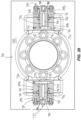
- a stern drive 12 may be configured with a steering actuator 610 including at least one electric motor 630 that is operatively connected to the gearcase 26 by a worm drive gearset including a worm gear 614 and a ring gear 616 (i.e., a worm ring).
- the illustrated steering actuator 610 includes a steering enclosure 620 formed on a front side of the lower portion 606 of the gearcase 26.
- the steering enclosure 620 is generally rectangular and includes an upper wall 621, a lower wall 622, opposing lateral side walls 623, and a removable hatch 626 that includes a front wall 624 and can be secured to the forward edges of the upper, lower, and side walls 621, 622, 623 to enclose the steering enclosure 620.
- the lateral side walls 623 each include an access opening 627 that provides access to the interior of the steering enclosure 620 and a corresponding cover plate 628 configured to seal said access opening 627.
- the drive assembly 20 is supported on the mounting assembly 16 by rigid mounting arms 608 that extend upward from the upper wall 621 of the steering enclosure 620 proximate the lateral sides thereof. Each mounting arm 608 is pivotably connected to the rigid mounting arms 104 of the rigid mounting plate 100, thereby suspending the drive assembly 20 from the mounting assembly 16.
- Some embodiments, however, may be configured with a different arrangement for supporting the drive assembly 20 on the mounting assembly 16.
- the steering actuator 610 includes two electric motors 630 that are supported on corresponding motor mounting brackets 632 that extend from the front wall 624 of the steering enclosure 620.
- the illustrated first and second electric motors 630 are aligned with each other such that they share a single output shaft 634.
- Each electric motor 630 is independently operable to rotate the output shaft 634 and steer the gearcase 26. This may be useful, for example, in order to increase the output torque of the output shaft 634, and so that the steering actuator 610 has a redundant motor configuration.
- the output shaft 634 extends between opposite ends 636, which are supported by bearings 638 that are received in corresponding recesses 639 formed in the cover plates 628, thereby supporting the output shaft 634 between the opposing cover plates 628.
- the worm gear 614 is mounted on a worm gear shaft 644 that extends between opposing ends 646 thereof. Each end 646 of the worm gear shaft 644 is supported by bearings 648 received in corresponding recesses 650 in the cover plates 628.
- the worm gear 614 is spaced longitudinally apart from the output shaft 634 and is coupled thereto by gearsets 642 positioned proximate the ends 636, 646 of the output shaft 634 and worm gear shaft 644.
- a first one of the electric motors 630 is operably coupled to the gearcase 26 by a first gearset 642 and a second one of the electric motors 630 is operably coupled to the gearcase 26 by a second gearset 642.
- each gearset 642 is configured as a pulley linkage.
- Each pulley linkage includes a driven wheel 654 secured to the shared output shaft 634, an idle wheel 656 secured to the worm gear shaft 644, and a pulley band 658 that extends around and connects the driven wheel 654 to the idle wheel 656.
- the driven wheels 654 pull on and advance the pulley band 658, thereby causing the idle wheels 656, the worm gear shaft 644, and the worm gear 614 to rotate.
- the worm gear 614 is operatively connected to the gearcase 26 by the ring gear 616.
- the ring gear 616 has a circular base 662 that is configured to be coupled to the gearcase 26, an annular wall 664 extending upwards from the circular base 662, radially outward gear teeth 666 formed around the radially outer surface of the annular wall 664, and a through bore 668 extending through the center of the circular base 662.
- the ring gear 616 is rotatably received in a hub 607 of the lower housing portion 606 of the gearcase 26 such that the teeth 666 of the ring gear 616 are meshed with the teeth 670 of the worm gear 614 and the driveshaft 24 extends through the driveshaft.
- rotation of the output shaft 634 by the electric motors 630 causes the gearcase 26 to rotate about the steering axis S.
- an operator may use the input device to control one or both of the electric motors 630.
- the electric motors 630 are powered to rotate the output shaft 634 in a first direction.
- the pulley gearsets 642 at either end 636 of the output shaft 634 force the worm gear shaft 644 to rotate in the first direction.
- the electric motors 630 are powered to rotate the output shaft 634 in a second direction.
- the pulley gearsets 642 at either end 636 of the output shaft 634 force the worm gear shaft 644 to rotate in the second direction.
- the teeth 670 of the worm gear 614 press against the teeth 666 of the ring gear 616 to rotate the ring gear 616 and gearcase 26 in an opposite direction about the steering axis S into a port-facing orientation so that the thrust force generated by the propulsors 30 turns the marine vessel in the starboard direction.
- the worm gear 614 and the ring gear 616 may be configured as a self-locking worm gearset.
- the worm gear 614 is engaged with the ring gear 616 via gear teeth 670 having a lead angle that causes the worm gear 614 to resist rotation of the ring gear 616 when the gearcase 26 is subjected to an external force.
- the lead angle of the worm gear teeth 670 may be less than or equal to 5 degrees to achieve a self-locking configuration. Other embodiments, however, may be configured with a lead angle that is greater than 5 degrees.
- At least one other parameter of the worm gear 614 and/or the ring gear 616 may be selected to achieve a self-locking worm gear configuration that resists back driving of the gearcase 26.
- the teeth 666 of the ring gear 616 extend 360 degrees around the annular wall 664 such that the steering actuator 610 can rotate the gearcase 26 360 degrees around the steering axis S without reversing the direction of rotation of the output shaft 634.
Landscapes
- Chemical & Material Sciences (AREA)
- Engineering & Computer Science (AREA)
- Combustion & Propulsion (AREA)
- Mechanical Engineering (AREA)
- Ocean & Marine Engineering (AREA)
- Power Steering Mechanism (AREA)
Abstract
Description
- The present disclosure relates to marine drives, and in particular marine drives having a hydraulically actuated steerable gearcase, and stern drives having a powerhead for propulsion, such as an electric motor.
- The following U.S. Patent provides background information.
-
U.S. Pat. No. 10,800,502 - This Summary is provided to introduce a selection of concepts which are further described herein below in the Detailed Description. This Summary is not intended to identify key or essential features of the claimed subject matter, nor is it intended to be used as an aid in limiting the scope of the claimed subject matter.
- In non-limiting examples disclosed herein, a stern drive is for a marine vessel. The stern drive may comprise a powerhead, a drive assembly configured to support a propulsor for generating a thrust force in water, the propulsor being powered by the powerhead, wherein the drive assembly comprises a driveshaft housing and a gearcase suspended from the driveshaft housing, the gearcase being steerable relative to the driveshaft housing, and a steering actuator configured to steer the gearcase relative to the driveshaft housing.
- In non-limiting examples, the powerhead comprises an electric motor. The steering actuator may comprise an electric motor and the electric motor may be located in the driveshaft housing. The electric motor and the gearcase may be operably engaged via a gearset. The gearset may comprise a pinion and a ring gear. The gearset may comprise a worm gear and a ring gear. The worm gear may be engaged with the ring gear via teeth having a lead angle which causes the worm gear to resist rotation of the ring gear when the gearcase is subjected to an external force.
- In non-limiting examples, the steering actuator may comprise a first electric motor operably coupled to the gearcase by a first gearset and a second electric motor operably coupled to the gearcase by a second gearset. The first electric motor and the second electric motor may be independently operable to steer the gearcase. The first electric motor and the second electric motor may operate a common output shaft. The gearcase may comprise a steering housing which extends into the driveshaft housing. The steering actuator may comprise a rack on the gearcase and a kingpin on the steering housing, wherein movement of the rack rotates the kingpin and thereby steers the gearcase relative to the driveshaft housing. The steering actuator may further comprise a cylinder containing the rack, wherein the rack is movable back and forth in the cylinder and thereby steers the gearcase relative to the driveshaft housing. A hydraulic pump may be configured to supply hydraulic fluid to the cylinder which moves the rack back and forth in the cylinder and thereby steers the gearcase relative to the driveshaft housing.
- In non-limiting examples, an electric motor may be configured to move the rack back and forth in the cylinder and thereby steer the gearcase relative to the driveshaft housing. The electric motor may rotate an output shaft coupled to the rack such that rotation of the output shaft in a first direction causes movement of the rack in a first direction relative to the kingpin and such that rotation of the output shaft in an opposite, second direction causes movement of the rack in an opposite, second direction. The output shaft may be coupled to the rack by a ball screw or a roller screw.
- In non-limiting examples, the stern drive may further comprise the propulsor and a driveshaft which operably couples the powerhead to the propulsor, wherein the driveshaft extends through the steering housing and is operably engaged with an output shaft supporting the propulsor. An angle gearset may be located in the gearcase, the angle gearset coupling the driveshaft to the output shaft so that rotation of the driveshaft causes rotation of the output shaft. Upper and lower bearings may facilitate steering of the steering housing relative to the driveshaft housing.
- In non-limiting examples disclosed herein, a marine drive is for propelling a marine vessel. The marine drive includes a drive assembly configured to support a propulsor for generating a thrust force in water, the drive assembly including a driveshaft housing and a gearcase suspended from the driveshaft housing, wherein the drive assembly is trimmable relative to the marine vessel about a trim joint. A steering actuator is configured to steer the gearcase relative to the driveshaft housing, and a pump is configured to pump a hydraulic fluid to and/or from the steering actuator via the trim joint.
- Optionally, the marine drive may comprise a mounting assembly configured to couple the driveshaft housing to the marine vessel. The hydraulic fluid may be conveyed through the mounting assembly and through the driveshaft housing. Optionally, the marine drive may include at least one mounting arm which pivotally couples the mounting assembly to the driveshaft housing, wherein the hydraulic fluid is conveyed through the at least one mounting arm. Optionally, the at least one mounting arm may be one of a port mounting arm and a starboard mounting arm, wherein the hydraulic fluid is conveyed through the port mounting arm and through the starboard mounting arm. Optionally, the port mounting arm and the starboard mounting arm may extend from a first one of the driveshaft housing and the mounting assembly and are coupled to a second one of the driveshaft housing and the mounting assembly along the trim joint. Optionally, the trim joint may pivotably couple a stationary member and a rotary member, wherein the hydraulic fluid is conveyed through the stationary member and through the rotary member. Optionally, the stationary member is on the mounting assembly and the rotary member is on the driveshaft housing. Optionally, the marine drive may include a first fluid passage in the stationary member, a second fluid passage in the rotary member, and a chamber in the trim joint which fluidly couples the first fluid passage and the second fluid passage. Optionally, the marine drive may include a third fluid passage which is fluidly coupled to the second fluid passage in the rotary member, wherein the third passage extends from the rotary member to the steering actuator.
- Optionally, the rotary member may include a stem which is rotatable within a cavity in the stationary member, the stem having at least one radial bore which is fluidly coupled to an annular passage which is fluidly coupled to the second fluid passage. Optionally, the marine drive may include at least one seal which seals an outer diameter surface of the stem to an inner diameter surface of the cavity. Optionally, the steering actuator may comprise a hydraulic cylinder. Optionally, the gearcase may include a steering housing which extends into the driveshaft housing, wherein the steering actuator comprises a rack on the gearcase and a kingpin on the steering housing, and wherein movement of the rack rotates the kingpin and thereby steers the gearcase relative to the driveshaft housing. Optionally, the steering actuator may include a cylinder containing the rack, the rack being movable back and forth in the cylinder to steer the gearcase relative to the driveshaft housing.
- In non-limiting examples, a marine drive is for propelling a marine vessel. The marine drive includes a drive assembly configured to support a propulsor for generating a thrust force in water, the drive assembly comprising a driveshaft housing and a gearcase suspended from the driveshaft housing. A mounting assembly is configured to couple the driveshaft housing to the marine vessel along a trim joint, wherein the drive assembly is trimmable relative to the mounting assembly about the trim joint. A steering actuator is configured to steer the gearcase relative to the driveshaft housing; and a pump is configured to pump a hydraulic fluid to and/or from the steering actuator via the trim joint.
- Optionally, the hydraulic fluid may be conveyed through the mounting assembly and through the driveshaft housing. Optionally, the trim joint may pivotably couple a stationary member and a rotary member, wherein the hydraulic fluid is conveyed through the stationary member and through the rotary member.
- In non-limiting examples, a marine drive is for propelling a marine vessel. The marine drive includes a drive assembly configured to support a propulsor for generating a thrust force in water, the drive assembly comprising a driveshaft housing and a gearcase suspended from the driveshaft housing. A mounting assembly is configured to couple the driveshaft housing to the marine vessel along a trim joint, wherein the drive assembly is trimmable relative to the mounting assembly about the trim joint. A steering actuator is configured to steer the gearcase relative to the driveshaft housing. A pump is configured to pump a hydraulic fluid to and/or from the steering actuator via passages which are entirely contained within the drive assembly and mounting assembly.
- Optionally, the pump may be mounted on an opposite side of the mounting assembly relative to the drive assembly such that the pump is located in the marine vessel and the drive assembly is located outside of the marine vessel. Optionally, the passages may include a first passage through the mounting assembly and a second passage through the drive assembly.
- The present disclosure includes the following figures.
-
Fig. 1 is a starboard side perspective view of a stern drive according to the present disclosure. -
Fig. 2 is a port side perspective view of the stern drive. -
Fig. 3 is a starboard side perspective view of the stern drive. -
Fig. 4 is a starboard side view of the stern drive. -
Fig. 5 is a perspective view looking down at a universal joint of the stern drive which couples a powerhead, which in the illustrated example includes an electric motor, to a driveshaft of the stern drive. -
Fig. 6 is an exploded view of the universal joint. -
Fig. 7 is a starboard side sectional view of the stern drive. -
Fig. 8 is a starboard side view of the stern drive in a trimmed-up position. -
Fig. 9 is a starboard side sectional view of the stern drive in the trimmed-up position. -
Fig. 10 is a starboard side perspective view of a mounting assembly which mounts the electric motor to the transom of a marine vessel. -
Fig. 11 is a starboard side perspective view of the stern drive in the trimmed-up position and steered ninety degrees off center (straight-ahead) so that the drive assembly of the stern drive is trimmed fully out of the water. -
Fig. 12 is a starboard side view of an example sound enclosure for the stern drive. -
Fig. 13 is a starboard side sectional view of the example shown inFig. 12 . -
Fig. 14 is a starboard side perspective view of a stern drive including a steering actuator. -
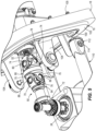
Fig. 15 is an exploded perspective view of the gearcase and steering actuator of the stern drive ofFig. 14 . -
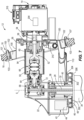
Fig. 16 is a view of section 16-16, taken inFig. 14 . -
Fig. 17 is a port side perspective view of another example of the gearcase and steering actuator for a stern drive. -
Fig. 18 is an exploded perspective view of the gearcase and steering actuator of the stern drive ofFig. 17 . -
Fig. 19 is a view of section 19-19, taken inFig. 17 . -
Fig. 20 is a starboard side perspective view of another example of a stern drive including a steering actuator. -
Fig. 21 is an exploded perspective view of the gearcase and steering actuator of the stern drive ofFig. 20 . -
Fig. 22 is a view of section 22-22, taken inFig. 20 . -
Fig. 23 is a starboard side perspective view of another example of a stern drive including a hydraulic steering actuator and a trim joint. -
Fig. 24 is another starboard side perspective view of the stern drive ofFig. 23 . -
Fig. 25 is a starboard side view of the stern drive ofFig. 24 . -
Fig. 26 is an exploded perspective view of the trim joint ofFig. 25 . -
Fig. 27 is a view of section 27-27, taken inFig. 25 . -
Fig. 28 is a view of section 28-28, taken inFig. 25 . -
Figs. 1-8 illustrate astern drive 12 for propelling a marine vessel in a body of water. Referring toFig. 1 , thestern drive 12 has a powerhead, which in the illustrated example is anelectric motor 14, a mountingassembly 16 which affixes theelectric motor 14 to and suspends theelectric motor 14 from thetransom 18 of the marine vessel, and adrive assembly 20 coupled to the mountingassembly 16 and suspended therefrom. The illustrated powerhead is not limiting and in other examples the powerhead may include an engine and/or a combination of an engine and an electric motor, and/or any other suitable means for powering a marine drive. The mountingassembly 16 is configured so that the powerhead which in the illustrated example is anelectric motor 14 is suspended (i.e., cantilevered) from the interior of thetransom 18, above the hull of the marine vessel. As will be further explained below, thedrive assembly 20 is trimmable up and down relative to the mountingassembly 16, including in non-limiting examples wherein a majority or an entirety of thedrive assembly 20 is raised completely out of the water. Thedrive assembly 20 has adriveshaft housing 22 containing adriveshaft 24 and agearcase 26 containing one or more output shaft(s) 28, e.g., one or more propulsor shaft(s). The output shaft(s) 28 extends from the rear of thegearcase 26 and support one or more propulsor(s) 30 configured to generate thrust in the water for propelling the marine vessel. The output shaft(s) 28 extend generally transversely to thedriveshaft 24. In the illustrated example, propulsor(s) 30 include two counter-rotating propellers. However this is not limiting and the present disclosure is applicable to other arrangements, including arrangements wherein one or more output shaft(s) 28 are not counter-rotating and/or wherein the one or more output shaft(s) 28 extend from the front of thegearcase 26, and/or wherein the propulsor(s) 30 include one or more impellers and/or any other mechanism for generating a propulsive force in the water. - Referring to
Figs. 1 and7 , thegearcase 26 is steerable about a steering axis S relative to thedriveshaft housing 22. Thegearcase 26 has a steeringhousing 32 which extends upwardly into thedriveshaft housing 22, as well as atorpedo housing 34 which depends from the steeringhousing 32. Anangle gearset 36 in thetorpedo housing 34 operably couples the lower end of thedriveshaft 24 to the output shaft(s) 28 so that rotation of thedriveshaft 24 causes rotation of the output shaft(s) 28, which in turn causes rotation of the propulsor(s) 30. - Referring to
Fig. 7 , upper andlower bearings housing 32 and thedriveshaft housing 22. The upper andlower bearings housing 32 relative to thedriveshaft housing 22. A steeringactuator 42 is configured to cause rotation of thegearcase 26 relative to thedriveshaft housing 22. In the illustrated example, the steeringactuator 42 is anelectric motor 44 located in thedriveshaft housing 22 and may be operatively engaged with thegearcase 26 via a gearset. Theelectric motor 44 has an output gear 46 (i.e., a pinion) which is meshed with aring gear 48 on the steeringhousing 32 so that rotation of theoutput gear 46 causes rotation of thegearcase 26 about the steering axis S. As further explained below, operation of theelectric motor 44 can be controlled via a conventional user input device located at the helm of the marine vessel or elsewhere, which facilitates control of the steering angle of thegearcase 26 and associated propulsor(s) 30. This facilitates steering control of the marine vessel. As discussed below in reference toFigs. 14-22 , the type and configuration of thesteering actuator 42 can vary from what is shown and in other examples could include one or more hydraulic actuators, electro-hydraulic actuators, and/or any other suitable actuator for causing rotation of thegearcase 26. Other suitable examples are disclosed in the above-incorporatedU.S. Patent No. 10,800,502 - Referring to
Figs. 5-7 , a universal joint 50 couples theelectric motor 14 to thedriveshaft 24 so that operation of theelectric motor 14 causes rotation of thedriveshaft 24, which in turn causes rotation of the output shaft(s) 28. Theuniversal joint 50 is also advantageously configured to facilitate trimming of thedrive assembly 20 an amount sufficient to raise at least a majority of thedrive assembly 20 out of the water, for example during periods of non-use. Theuniversal joint 50 has aninput member 52 which is rotatably engaged with anoutput shaft 54 of theelectric motor 14, anoutput member 64 which is rotatably engaged with thedriveshaft 24, and anelongated body 66 which rotatably couples theinput member 52 to theoutput member 64. Theinput member 52 has an externally-splined input shaft 62 andinput arms 63 which form a U-shape. Theoutput member 64 has anoutput shaft 68 andoutput arms 70 which form a U-shape. Theelongated body 66 has a first pair ofarms 74 which form a U-shape and an opposing second pair ofarms 76 which form a U-shape. Input pivot pins 78, 80 pivotably couple theinput arms 63 of theinput member 52 to the first pair ofarms 74 of theelongate body 66 along a firstinput pivot axis 82 and along a secondinput pivot axis 84 which is perpendicular to the firstinput pivot axis 82. Output pivot pins 86, 88 pivotably couple theoutput arms 70 of theoutput member 64 to the second pair ofarms 76 of theelongated body 66 along a firstoutput pivot axis 90 and along a secondoutput pivot axis 92 which is perpendicular to the firstoutput pivot axis 90. - Referring to
Fig. 7 , an internallysplined sleeve 56 is rotatably supported in the mountingassembly 16 by inner andouter bearings output shaft 54 of theelectric motor 14 is fixed to thesplined sleeve 56 so that rotation of theoutput shaft 54 causes rotation of thesplined sleeve 56. The externally-splined input shaft 62 of theuniversal joint 50 extends into meshed engagement with thesplined sleeve 56 so that rotation of thesplined sleeve 56 causes rotation of theinput member 52. Theoutput shaft 68 of theuniversal joint 50 is coupled to thedriveshaft 24 by anangle gearset 72 located in thedriveshaft housing 22 and configured so that rotation of theoutput member 64 causes rotation of thedriveshaft 24. Thus, it will be understood that operation of theelectric motor 14 causes rotation of theuniversal joint 50, which in turn causes rotation of thedriveshaft 24 and output shaft(s) 28. The splined engagement between theinput member 52 andsplined sleeve 56 also advantageously permits telescoping movement of theinput member 52 during trimming of thedrive assembly 20, as will be further described below with reference toFigs 8-9 . A flexible bellows 94 encloses the universal joint 50 relative to the mountingassembly 16 and thedriveshaft housing 22. - Referring now to
Figs. 1-4 and7 , the mountingassembly 16 has arigid mounting plate 100, a vibration dampening (e.g., rubber or other pliable and/or resilient material) mountingring 102, and arigid mounting ring 103 which is fastened to thetransom 18 byfasteners 105 and afastening ring 107 to couple the vibration dampening mountingring 102 and rigid mountingplate 100 to thetransom 18. A pair of rigid mountingarms 104 extends rearwardly from therigid mounting plate 100 and is pivotably coupled to a rigid, U-shaped mountingbracket 108 extending forwardly from the top of thedriveshaft housing 22. The pivot joint between the rigid mountingarms 104 and mountingbracket 108 defines a trim axis T (seeFig. 2 ) about which thedrive assembly 20 is pivotably (trimmable), up and down relative to the mountingassembly 16. The type and configuration of mountingassembly 16 can vary from what is shown, and a non-limiting example of the mountingassembly 16 is described herein below with reference toFigs. 14-21 . -
Trim cylinders 110 are located on opposite sides of the mountingassembly 16. Thetrim cylinders 110 have afirst end 112 pivotably coupled to therigid mounting plate 100 at a first pivot joint 114 and an opposite,second end 116 pivotably coupled to thedrive assembly 20 at asecond pivot joint 118. A hydraulic actuator 120 (seeFig. 11 ) which in this example includes a pump and associated valves and line components, is mounted to the interior of therigid mounting plate 100. Thehydraulic actuator 120 is hydraulically coupled to thetrim cylinders 110 via a least one internal passage through the mountingassembly 16 and the first pivot joint 114, advantageously so that there are no other hydraulic lines located on the exterior of thestern drive 12, or otherwise outside the marine vessel so as to be subjected to wear and/or damage from external elements. Thehydraulic actuator 120 is operable to supply hydraulic fluid to thetrim cylinders 110 via the noted internal passage to cause extension of thetrim cylinders 110 and alternately to cause retraction of thetrim cylinders 110. Extension of thetrim cylinders 110 pivots (trims) thedrive assembly 20 upwardly relative to the mountingassembly 16 and retraction of thetrim cylinders 110 pivots (trims) thedrive assembly 20 downwardly relative to the mountingassembly 16. Examples of a suitable hydraulic actuator are disclosed in the above-incorporatedU.S. Patent No. 9,334,034 - By comparison of
Figs. 7-9 , it will be seen that the universal joint 50 advantageously facilitates trimming of thedrive assembly 20 about the trim axis T while maintaining operable connection between theelectric motor 14 and the output shaft(s) 28. In particular, as thedrive assembly 20 is trimmed, theelongated body 66 is configured to also pivot about the first and/or second input pivot axes 82, 84 (via input pivot pins 78, 80), and theoutput member 64 is configured to also pivot about the first and/or second output pivot axes 90, 92 (via output pivot pins 86, 88). As explained above, theinput shaft 62 is coupled to the internally splinedsleeve 56 by a splined coupling so that theinput shaft 62 is free to telescopically move outwardly relative to the internally splinedsleeve 56 and mountingassembly 16 when thedrive assembly 20 is trimmed up and so that theinput shaft 62 is free to telescopically move inwardly relative to the mountingassembly 16 when thedrive assembly 20 is trimmed down. - A
controller 200 is communicatively coupled to theelectric motor 14, the steeringactuator 42, and thehydraulic actuator 120. Thecontroller 200 is configured to control operation of theelectric motor 14, the steeringactuator 42, and thehydraulic actuator 120. More specifically, thecontroller 200 is configured to control theelectric motor 14 to rotate theuniversal joint 50, thedriveshaft 24 and the output shaft(s) 28, thereby controlling the thrust force generated by the propulsor(s) 30 in the water. Thecontroller 200 is configured to control thesteering actuator 42 to rotate thegearcase 26 about the steering axis S. Thecontroller 200 is configured to control thehydraulic actuator 120 to extend and alternately to retract thetrim cylinders 110 to trim thedrive assembly 20 about the trim axis T. - The type and configuration of the
controller 200 can vary. In non-limiting examples, thecontroller 200 has a processor which is communicatively connected to a storage system comprising a computer readable medium which includes volatile or nonvolatile memory upon which computer readable code and data is stored. The processor can access the computer readable code and, upon executing the code, carry out functions, such as the controlling functions for theelectric motor 14, steeringactuator 42, and thehydraulic actuator 120. In other examples thecontroller 200 is part of a larger control network such as a controller area network (CAN) or CAN Kingdom network, such as disclosed inU.S. Patent No. 6,273,771 . A person having ordinary skill in the art will understand that various other known and conventional computer control configurations could be implemented and are contemplated by the present disclosure, and that the control functions described herein may be combined into a single controller or divided into any number of distributed controllers which are communicatively connected. - The
controller 200 is in electrical communication with theelectric motor 14, the steeringactuator 42, and thehydraulic actuator 120 via one or more wired and/or wireless links. In non-limiting examples, the wired and/or wireless links are part of a network, as described above. Thecontroller 200 is configured to control theelectric motor 14, the steeringactuator 42, and thehydraulic actuator 120 by sending and optionally by receiving said signals via the wired and/or wireless links. Thecontroller 200 is configured to send electrical signals to theelectric motor 14 which cause theelectric motor 14 to operate in a first direction to rotate theuniversal joint 50, thedriveshaft 24 and the output shaft(s) 28 in a first direction, thereby generating a first (e.g., forward) thrust force in the water via the propulsor(s) 30, and alternately to send electric signals to theelectric motor 14 which cause theelectric motor 14 to operate in an opposite, second direction, to rotate theuniversal joint 50, thedriveshaft 24 and the output shaft(s) 28 in an opposite direction which generates a second (e.g., reverse) thrust force in the water via the propulsor(s) 30. Thecontroller 200 is configured to send electric signals to thesteering actuator 42 which cause thesteering actuator 42 to rotate thegearcase 26 in a first direction about the steering axis S and alternately to send electric signals to thesteering actuator 42 which cause thesteering actuator 42 to rotate thegearcase 26 in an opposite direction about the steering axis S. Thecontroller 200 is configured to send electrical signals to thehydraulic actuator 120 which cause thehydraulic actuator 120 to provide hydraulic fluid to one side of thetrim cylinders 110 to extend thetrim cylinders 110 and trim thedrive assembly 20 upwardly relative to the mountingassembly 16 and alternately to send electric signals to thehydraulic actuator 120 which cause thehydraulic actuator 120 to provide hydraulic fluid to an opposite side of thetrim cylinders 110 to retract thetrim cylinders 110 and trim thedrive assembly 20 downwardly relative to the mountingassembly 16. - A
user input device 202 is provided for inputting a user-desired operation of theelectric motor 14, and/or a user desired operation of thesteering actuator 42, and/or a user-desired operation of thehydraulic actuator 120. Upon input of the user-desired operation, thecontroller 200 is programmed to control theelectric motor 14, and/or thesteering actuator 42, and/or thehydraulic actuator 120 accordingly. Theuser input device 202 can include any conventional device which can be communicatively connected to thecontroller 200 for inputting a user-desired operation, including but not limited to one or more switches, levers, joysticks, buttons, touch screens, and/or the like. - Referring to
Fig. 7 , one or more sensor(s) 204 are provided for directly or indirectly sensing a rotational orientational position of theuniversal joint 50 and communicating this information to thecontroller 200. In non-limiting examples, thesensor 204 comprises one or more conventional magnetic pick-up coil(s), Hall-effect sensor(s), magneto-resistive element (MRE) sensor(s), and/or optical sensor(s), such as are available for purchase from Parker Hannifin Corp., among other places. The sensor(s) 204 may be configured to sense the orientational position of the universal joint 50 by sensing the rotational position of the output shaft of theelectric motor 14 and/or the rotational position of the internally splinedsleeve 56 and/or by sensing the rotational position of the input gear of theangle gearset 72, for example. In other examples, the sensor(s) 204 may also or alternately be configured to directly sense the orientational position of one or more rotatable component of theuniversal joint 50. The location of the one or more sensor(s) can vary, but preferably is located to be able to accurately sense a rotating part of the assembly for which an orientation between the splines and gears is known. - The
controller 200 is configured to automatically cause theelectric motor 14 to rotate the universal joint 50 into the neutral position shown in the figures (e.g., seeFigs. 5 and7 ), wherein the firstinput pivot axis 82 and the firstoutput pivot axis 90 are aligned with each other and generally parallel to the trim axis T. This advantageously facilitates trimming of thedrive assembly 20 fully out of the water. More specifically, rotating the universal joint 50 into the neutral position with the firstinput pivot axis 82 and the firstoutput pivot axis 90 oriented generally parallel to the trim axis T locates the first pair ofarms 74 at a ninety degree offset from theinput arms 63 of theinput member 52 and thus permits the first pair ofarms 74 of theelongated body 66 to pivot through a maximum allowable range about the firstinput pivot axis 82 within the U-shape formed by theinput arms 63, as shown inFig. 9 . Similarly, rotating the universal joint 50 into the neutral position locates theoutput arms 70 of theoutput member 64 at a ninety-degree offset from the second pair ofarms 76 of theelongated body 66 and thus permits theoutput arms 70 to pivot through a maximum allowable range about the firstoutput pivot axis 90 within the U-shape formed by the second pair ofarms 76, as shown inFig. 9 . - The
controller 200 is advantageously programmed to automatically operate theelectric motor 14 to rotate the universal joint 50 into the neutral position as indicated by thesensor 204 based upon an operational state of thestern drive 12. The operational state can for example include change in an on/off state of the electric motor 14 (for example a key on or key off event) and/or any other designated programmed request or request input to thecontroller 200 via theuser input device 202. - In a non-limiting example, a user can actuate the
user input device 202 to command thecontroller 200 to control thehydraulic actuator 120 to trim thedrive assembly 20 into a fully raised, storage position. Upon receiving said command, thecontroller 200 is programmed to automatically control theelectric motor 14 to rotate the universal joint 50 into the noted neutral position. As explained above, this advantageously facilitates trimming all or at least a majority of thedrive assembly 20 out of the water. For example the majority may include all of thedriveshaft housing 22 and a majority of thegearcase 26. Referring toFig. 11 , thecontroller 200 can be also configured to automatically operate thesteering actuator 42 to steer (i.e., rotate) thedrive assembly 20 about the steering axis S, for example into the position shown, which is ninety degrees offset to either one of the port or starboard sides. This can occur prior to, during, or after thedrive assembly 20 is trimmed upwardly via theuniversal joint 50. Steering thedrive assembly 20 into the position shown (or into the 180 degree opposite position of what is shown) advantageously further elevates the lowermost point of the drive assembly 20 (which typically is on thetorpedo housing 34 or skeg of the gearcase 26) further above the waterline W, thus ensuring that the entirety of thedrive assembly 20, including all of thedriveshaft housing 22 and all of thegearcase 26, is positioned out of the body of water. Thus the present disclosure contemplates methods for operating thestern drive 12, including the steps of operating theelectric motor 14 to rotate the universal joint 50 into the aforementioned neutral position, which facilitates trimming of thedrive assembly 20 upwardly relative to the rest of thestern drive 12, and optionally also steering thegearcase 26 relative to thedriveshaft housing 22, before, during or after the trimming of thedrive assembly 20, thereby moving an entirety of thedrive assembly 20 further upwardly relative to thestern drive 12 and ensuring that the entirety of thedrive assembly 20 is positioned out of the body of water. This advantageously locates the majority or entirety of thedrive assembly 20 out of the body of water during periods of non-use, thus preventing deleterious effects of the water on thedrive assembly 20. - Referring to
Fig. 7 , thestern drive 12 has a cooling system for cooling various components thereof, including for example theelectric motor 14. In the non-limiting example shown in the drawings, the cooling system includes an open loop cooling circuit for circulating cooling water from the body of water in which thestern drive 12 is situated and then discharging the cooling water back to the body of water. The open loop cooling circuit includes an intake inlet 300 (seeFig. 1 ) on thegearcase 26 which is connected to anannular cooling channel 302 defined between a lowerannular flange 304 on the lower end of thedriveshaft housing 22 and anannular flange 306 on the top of thegearcase 26. Reference is made to the above-incorporatedU.S. Patent No. 1 0,800,502 flexible conduit 308 is coupled to thedriveshaft housing 22 and configured to convey the cooling water from theannular cooling channel 302 to acooling water pump 310 mounted on the outside of therigid mounting plate 100. The coolingwater pump 310 is configured to draw the cooling water in through theintake inlet 300, seeFig. 1 , through theannular cooling channel 302, and through theflexible conduit 308. The coolingwater pump 310 pumps the cooling water through the mountingassembly 16 to aheat exchanger 314 and then to anoutlet 315 shown inFig. 10 . In the illustrated example, thestern drive 12 further includes a closed loop cooling circuit having apump 312 for pumping cooling fluid such as a mixture of water and ethylene glycol through theheat exchanger 314, exchanging heat with the cooling water in the open loop cooling circuit. The mixture of water and ethylene glycol is circulated past theelectric motor 14, an associatedinverter 316, and one or more batteries for powering theelectric motor 14, thus cooling these components. - Referring to
Figs. 12 and13 , in non-limiting examples, thestern drive 12 also has asound absorbing enclosure 400 which encloses the inboard portions of thestern drive 12 and advantageously limits noise emanating from thestern drive 12. Thesound absorbing enclosure 400 can be made of foam and/or any other conventional sound absorbing material, such as a sheet molding compound (SMC). In the illustrated example, thesound absorbing enclosure 400 completely encloses the inboard components of thestern drive 12 and is fixed to the mountingassembly 16. In other examples, thesound absorbing enclosure 400 is configured to only enclose some of the inboard components of thestern drive 12. - As previously discussed, some embodiments of a
stern drive 12 may be configured with a steering arrangement that is different than the steering arrangement of thestern drive 12 ofFigs. 1-13 . For example, referring toFigs. 14-16 , embodiments of astern drive 12 may be configured with a hydraulicly actuatedsteering actuator 410. Similar to the embodiments ofFigs. 1-13 , thestern drive 12 ofFigs 14-16 includes thepowerhead 14 configured to power the propulsor 30 (seeFig. 1 ) and the rest of adrive assembly 20 supported on thetransom 18 of the marine vessel by a mountingassembly 16. Thedrive assembly 20 is configured to support apropulsor 30 for generating a thrust force in water and includes thepowerhead 14, adriveshaft housing 22, and agearcase 26 suspended from thedriveshaft housing 22. Thedriveshaft housing 22 includes anupper housing portion 404 which houses theangle gearset 72 which couples the universal joint 50 to thedriveshaft 24 and alower housing portion 406 which is coupled to the second ends 116 of thetrim cylinders 110 at the second pivot joints 118 on the port and starboard sides of the lowerdriveshaft housing portion 406. Thegearcase 26 is steerable about a steering axis S (seeFig. 15 ) relative to thedriveshaft housing 22, and thesteering actuator 410 on thedriveshaft housing 22 is configured to steer thegearcase 26 relative to thedriveshaft housing 22. - Referring to
Figs. 15 and16 , thesteering actuator 410 is a hydraulically actuated mechanism positioned on the lowerdriveshaft housing portion 406. Thesteering actuator 410 includes apiston cylinder 412 that is positioned on the front side of the lowerdriveshaft housing portion 406 and extends laterally from the port side to the starboard side of thestern drive 12. In the illustrated embodiments thepiston cylinder 412 includes amiddle cylinder section 413 that is formed in the lowerdriveshaft housing portion 406 and opposing port andstarboard cylinder extensions driveshaft housing 22 withfasteners 418. Arack 420 is slidably received in thepiston cylinder 412 and includes a generallycylindrical body 422 that extends between opposing ends 424 thereof. Eachend 424 of therack 420 includesannular grooves 426 formed around thebody 422 that are configured to receive a radially outer seal 428 (i.e., an O-ring) and/or a slide bearing 430 (Fig. 16 ). When therack 420 is positioned in thepiston cylinder 412, the radiallyouter seals 428 form a seal with the radially inner sidewalls of thepiston cylinder 412 and define aport side chamber 434 and astarboard side chamber 436 within thepiston cylinder 412. The port andstarboard cylinder extensions inlet 438 through which hydraulic fluid may be pumped into the port and/orstarboard chambers - In the illustrated embodiments, hydraulic fluid may be pumped into or out of the
steering actuator 410 from a conventionalhydraulic manifold 411 including a conventional hydraulic fluid pump and control valves (Fig. 14 ) configured to supply hydraulic fluid to thepiston cylinder 412. Therack 420 is configured to slide back and forth in thepiston cylinder 412 under pressure provided by hydraulic fluid which is selectively pumped into the port and/orstarboard chambers hydraulic manifold 411 may be positioned in the marine vessel and is connected to theinlets 438 on thecylinder extensions Fig. 14 ) that extend fromports 441 in thecylinder extensions hydraulic manifold 411. The conduits may extend over thetransom 18 and mountingassembly 16 into the marine vessel. Some embodiments, however, may be configured with a different arrangement for connecting thesteering actuator 410 to ahydraulic manifold 411. For example, as discussed below in reference toFigs. 23-28 , at least a portion of a hydraulic supply line may extend through the mountingassembly 16 and/or thedriveshaft housing 22. The supply of pressurized hydraulic fluid from the manifold 411 to thepiston cylinder 412 can be controlled by a conventional valve arrangement and a conventional operator input device for controlling steering movement of the marine drive. - Referring to
Figs. 15 and16 , thegearcase 26 includes a steeringhousing 444 that is arranged concentrically with the steering axis S and extends upwards into thedriveshaft housing 22. The illustratedsteering housing 444 is configured to be coupled to a body of thegearcase 26 at aflange 446 formed around the lower end of the steeringhousing 444 such that the rotational position of the steeringhousing 444 is fixed relative to the body of thegearcase 26. Asteering column 448 extends upwards from the lower end of the steeringhousing 444 to the upper end thereof. A throughbore 450 concentric with the steering axis S extends through the steeringhousing 444, and thedriveshaft 24 is configured to extend through the throughbore 450 from the universal joint 50 to theangle gearset 36 in thetorpedo housing 34. - In the illustrated embodiments, the
steering actuator 410 is operatively engaged with the steeringhousing 444 by a gearset configured as a rack and pinon gearset. Therack 420 includes a plurality ofteeth 452 extending along a rear-facingside 453 of therack 420. The steeringhousing 444 includes akingpin 454 formed around thesteering column 448 between the upper and lower ends thereof. The illustratedkingpin 454 includes a plurality of teeth 456 that are arranged radially around thesteering column 448 and configured to mesh with and engage theteeth 452 on therack 420. The sets ofteeth 452, 456 are meshed together so that back-and-forth movement of therack 420 within thepiston cylinder 412 causes theteeth 452 on therack 420 to move the teeth 456 of thekingpin 454. The back-and-forth movement of therack 420 causes corresponding back-and-forth rotational movement of the steeringhousing 444 and thegearcase 26 about the steering axis S. Thus, operation of thesteering actuator 410causes steering housing 444 to rotate with thegearcase 26 about the steering axis S with respect to the steeringhousing 32 andpowerhead 14, thereby steering thegearcase 26 relative to thedriveshaft housing 22. - In the illustrated embodiments, the
kingpin 454 includes gear teeth 456 that are formed 180 degrees around thesteering column 448. Thus, thegearcase 26 has a steering range of 180 degrees and can be rotated 90 degrees clockwise and counterclockwise about the steering axis S relative to a straight-ahead position. Some embodiments, however, may be configured with a steering range that is more than 180 degrees or less than 180 degrees. For example, astern drive 12 can be configured with a kingpin having teeth formed 120 degrees around the steering column to provide a steering range of 120 degrees (60 degrees clockwise and counterclockwise relative to a straight-ahead orientation). - Hydraulic connectors extending from a marine vessel to a stern drive supported on the vessel are often subject to bending and/or abrasion which may damage the connectors over extended periods of time. For stern drives that require large diameter hydraulic connectors or a plurality of hydraulic connectors, the rigidity of these connectors may interfere with the steering and trimming of the marine drive. Lengthy connectors extending between the stern drive and the marine vessel can affect the styling of the marine drive and can otherwise be inconvenient for a number of reasons. Through research and experimentation, the present inventors determined it would be advantageous to provide a hydraulic supply line that is concealed and integrated into the mounting assembly and/or drive assembly of a stern drive. The present disclosure is a result of the present inventors efforts in this regard.
- Referring to
Figs 23-28 , some embodiments of astern drive 12 may be configured with anovel mounting assembly 16 and trim joint 710 including an integratedhydraulic supply line 706 configured to transport hydraulic fluid throughfluid passages assembly 16 and/or trim joint 710 between thehydraulic pump 411 and thesteering actuator 410 on thelower portion 406 of thedriveshaft housing 22. Thestern drive 12 extends from top to bottom in an axial direction AX, from front to back in a longitudinal direction LO which is perpendicular to the axial direction AX, and from side to opposite side in a lateral direction LA which is perpendicular to the axial direction AX and perpendicular to the longitudinal direction LO. The trim joint 710 is generally symmetrical in the lateral direction LA, so that the components on the port side of the trim joint 710 are the same as or are mirror images of the components on the starboard side of the trim joint. As such, the descriptions provided below regarding components on one side of the trim joint 710 equally apply to the components on the opposite side of the trim joint 710. - Similar to the embodiments of
Figs. 14-16 , thestern drive 12 ofFigs 23-28 includes adrive assembly 20 that is supported on thetransom 18 of the marine vessel by a mountingassembly 16. Thedrive assembly 20 is configured to support apropulsor 30 for generating a thrust force in water and includes thepowerhead 14, adriveshaft housing 22, and agearcase 26 suspended from thedriveshaft housing 22. Thedriveshaft housing 22 includes anupper housing portion 404 which houses theangle gearset 72 that couples the universal joint 50 to thedriveshaft 24 and alower housing portion 406 which is coupled to the second ends 116 of thetrim cylinders 110 at the second pivot joints 118 on the port and starboard sides of the lowerdriveshaft housing portion 406. Thegearcase 26 is steerable about a steering axis S relative to thedriveshaft housing 22, and asteering actuator 410 on thedriveshaft housing 22 is configured to steer thegearcase 26 relative to thedriveshaft housing 22. - The mounting
assembly 16 includes arigid mounting plate 100 configured to support at least some of the various components of thedrive assembly 20 on thetransom 18 on the marine vessel. Therigid mounting plate 100 is recessed into the hull of the marine vessel and includes an interior space with aforward wall 150, a rear opening defined by anannular flange 154, and sidewalls 156 that extend longitudinally between theforward wall 150 and theannular flange 154. Thedrive assembly 20 is supported on therigid mounting plate 100 via a port siderigid mounting arm 104a and a starboard side rigid mounting arm 140b that extend rearwardly from theforward wall 150 of therigid mounting plate 100. The rigid mountingarms 104 are pivotably coupled to a rigid, U-shaped mountingbracket 108 of thedriveshaft housing 22 that extends forwardly from theupper portion 404 of thedriveshaft housing 22. The port and starboard rigid mountingarms 104a, 104b are coupled to respective port and starboard mountingbracket arms 109a, 109b of the mountingbracket 108 at a trim joint 710 that defines a trim axis T about which thedrive assembly 20 is trimmable up and down relative to the mountingassembly 16. - The
stern drive 12 ofFigs. 23-28 is configured with ahydraulic steering actuator 410 similar to that ofFigs. 14-16 . Ahydraulic pump 411 is configured to pump a hydraulic fluid to and/or from thesteering actuator 410 via the trim joint 710 andpassages drive assembly 20 and/or the mountingassembly 16. As previously discussed in reference toFigs. 14-16 , the steering actuator includes ahydraulic cylinder 412 on thedriveshaft housing 22, and thegearcase 26 includes a steeringhousing 444 which extends into thedriveshaft housing 22. Thesteering actuator 410 includes arack 420 on thegearcase 26 and akingpin 454 on the steeringhousing 444. Therack 420 is positioned in thehydraulic cylinder 412 and is movable back and forth in thecylinder 412 to steer thegearcase 26 relative to thedriveshaft housing 22. Movement of therack 420 rotates thekingpin 454 and thereby steers thegearcase 26 relative to thedriveshaft housing 22. Some embodiments, however, may include a differently configured hydraulic steering actuator. - Referring to
Fig. 26 , the port and starboard sides of the trim joint 710 include a stationary member 714 (e.g., the rigid mounting arms 140a, 104b) and a rotary member 716 (e.g., the mountingbracket arms 109a, 109b), and the hydraulic fluid is conveyed through thestationary members 714 and through therotary members 716 viainternal passages 720. 750. In the illustrated embodiments, thestationary members 714 are on the mountingassembly 16 and therotary members 716 are on thedriveshaft housing 22. Some embodiments, however, may be configured with thestationary members 714 on thedriveshaft housing 22 and therotary members 716 on the mountingassembly 16. - On the port and starboard sides, the
hydraulic supply line 706 includes afirst fluid passage 720 that extends through the mountingassembly 16 and thestationary member 714. As illustrated inFigs. 24 and25 , the firstfluid passages 720 each have an inlet 722 on thefront surface 151 of thefront wall 150 of therigid mounting plate 100. The inlets 722 may be connected to thehydraulic pump 411, which is mounted on an opposite side of the mountingassembly 16 relative to thedrive assembly 20 such that thehydraulic pump 411 is located in the marine vessel and thedrive assembly 20 is located outside of the marine vessel. The firstfluid passages 720 extend from the corresponding inlet 722, through therigid mounting plate 100 and the rigid mountingarms 104 arms, and to the trim joint 710. - Referring to
Figs. 26 and27 , the firstfluid passages 720 through the mounting assembly extend through the mountingarms 104 tocavities 724 of the trim joint 710, which are positioned at the distal ends 726 of the stationary members 714 (i.e., mounting arms 104) in the illustrated embodiments. Thecavities 724 are generally cylindrical and include openings that face laterally outward away from each other. Thecavities 724 are configured to rotatably receive a corresponding part of the rotary member 716 (i.e., the pin member 732) such that thecavities 724 define the trim axis T about which thedrive assembly 20 is pivoted. - The
rotary members 716 are configured as the port and starboard mountingbracket arms 109a, 109b of theU-shaped bracket 108. A lateral throughbore 730 is formed through the distal ends 731 of therotary members 716 and is configured to receive apin member 732 that couples therotary members 716 to thestationary members 714. Referring toFig. 27 , thedriveshaft housing 22 includes secondfluid passages 750 in therotary members 716. Eachsecond fluid passage 750 extends through the port or starboard mountingbracket arm 109a, 109b from the throughbore 730 at the trim joint 710 to anoutlet port 752 proximate aback end 751 of theU-shaped bracket 108. Thesecond passages 750 generally follow the curvature of the mounting bracket arms 109 and include alinear segment 754 that extends longitudinally from the throughbores 730 towards thedriveshaft housing 22 and a curved segment 756 that turns laterally inward to theoutlet port 752 proximateback end 751 of theU-shaped bracket 108. - Referring to
Figs. 26-28 , thepin members 732 each have a generallycylindrical stem 734 that extends from aflange 736 to an opposing end 738 thereof. Anaxial chamber 740 extends through thestem 734 from aninlet 742 at the end 738 of thestem 734 towards theflange 736. Proximate theflange 736, thepin member 732 includes at least oneradial bore 744 that extends radially outward from theaxial chamber 740 to anannular passage 746 formed around thestem 734. In the illustrated embodiments, thepin members 732 each include fourradial bores 744 that are spaced around thestem 90 degrees apart from each other. Some embodiments, however, may have a different number of radial bores, at least one of which may not be evenly spaced around the stem. - The
stem 734 of eachpin member 732 is configured to extend through the lateral throughbore 730 in therotary member 716 and into thecavity 724 on the correspondingstationary member 714 such that thestem 734 is rotatable within thecavity 724.Openings 737 formed in theflange 736 are configured to receivefasteners 728 that couple thepin member 732 to correspondingopenings 748 formed around the throughbore 730, thereby securing thepin member 732 to therotary member 716 such that thepin member 732 and therotary member 716 rotate together about the trim axis T. The stems 734 of thepin members 732 are supported in thecavities 724 in thestationary members 714 bybushings 758, which may reduce the friction between thestems 734 and the inner diameter of thecavities 724 such that thepin members 732 may rotate relative to thestationary members 714. Anannular seal member 760 extends around eachstem 734 and seals the outer diameter surface of thestem 734 to an inner diameter surface of thecavity 724. - In the illustrated embodiment, the trim joint 710 includes two
seal members rotary members 716 and thepin members 732. Afirst seal member 764 is positioned in anannular groove 766 formed around the interior diameter of the throughbore 730 extending through eachstationary member 714. Thefirst seal members 764 forms a seal between the outer diameter of thestem 734 and the inner diameter of the throughbore 730. Thesecond seal member 768 is positioned in a circular groove 770 formed on a laterally outward facingsurface 771 of therotary member 716 around the throughbore 730. Thesecond seal member 768 forms a seal between the laterally outward facingsurface 771 andflange 736 on thepin member 732. - With the
pin members 732 rotatably coupling the port rigid mountingarm 104a to the port mountingbracket arm 109a and the starboard rigid mounting arm 104b to the starboard mounting bracket arm 109b, therotary members 716 are coupled to thestationary members 714, thereby securing thedrive assembly 20 to the mountingassembly 16. - As illustrated in
Figs. 27 and28 , thecavities 724 and/or thestems 734 of thepin members 732 are dimensioned so that avoid 774 is present between the end 738 of the pin members and theback walls 725 of thecavities 724. Thevoids 774 are in fluid communication with the firstfluid passages 720 such that hydraulic fluid may flow into theaxial chambers 740 extending through thestems 734 of thepin members 732. Theannular passages 746 formed around thestems 734 are in fluid communication with thesecond passages 750 such that hydraulic fluid may flow throughaxial chambers 740 into thesecond passages 750 via the radial bores 744 and theannular passage 746. Thus, on the port and starboard sides of the trim joint 710, thevoid 774, theaxial chamber 740, the radial bores 744 and theannular passage 746 form achamber 776 in the trim joint 710 which fluidly couples thefirst fluid passage 720 and thesecond fluid passage 750. - Hydraulic fluid may be pumped from each
second fluid passage 750 to thesteering actuator 410 via correspondingthird passages 780 on the port and starboard sides of thestern drive 12. Referring toFigs. 23 .25 , and27 , the illustratedthird passages 780 are configured asconduits 440 extending between theoutlets 752 of thesecond passages 750 to acylinder inlet port 441 on the corresponding one of the port andstarboard cylinder extensions conduit 440 has afirst end 782 that is received in one of theoutlets 752 of thesecond passages 750 and asecond end 784 that is received in one of thecylinder ports 441. The conduit 440a on the port side of thestern drive 12 extends from the port side outlet 752a in the port side mountingbracket arm 109a to the cylinder inlet 411a on theport cylinder extension 414. The conduit 440b on the starboard side of thestern drive 12 extends from the starboard side outlet 752b in the starboard side mounting bracket arm 109b to the cylinder inlet 411b on thestarboard cylinder extension 416. Since theU-shaped mounting bracket 108 of thedriveshaft housing 22 does not move relative to thesteering actuator 410 as thedrive assembly 20 is trimmed up or down, theconduits 440 do not bend as thedrive assembly 20 is trimmed. This may be useful, for example, in order to reduce wear on the conduits by limiting their motion and preventing the conduits from abrasively rubbing against another component of thestern drive 12. Some embodiments, however, may include a differently configured third passage. For example, the drive assembly may include a third fluid passage that extends entirely through thedriveshaft housing 22. - To steer the
stern drive 12, an operator may use the input device to control thehydraulic pump 411 to supply pressurized hydraulic fluid to thesteering actuator 410 via thepassages assembly 16, trim joint 710, anddriveshaft housing 22. To rotate thegearcase 26 into a starboard orientation to conduct a turn towards the port side of the marine vessel, pressurized hydraulic fluid is supplied to theport side chamber 434 via the port sidehydraulic supply line 706. Thehydraulic pump 411 pumps hydraulic fluid into the port side inlet 722 and through the port siderigid mounting arm 104a via thefirst passage 720 and into thechamber 776 in the trim joint 710. The hydraulic fluid passes through thechamber 776 in the trim joint 710 (i.e., through the void 774, theaxial chamber 740 of thepin member 732, the radial bore(s) 744, and the annular passage 746) and into thesecond passage 750 in the port side mountingbracket arm 109a. The hydraulic fluid then flows through thesecond passage 750, out thecorresponding outlet 752 on theU-shaped mounting bracket 108, and through theconduit 440 to thecylinder inlet port 441 on theport cylinder extension 414. Hydraulic fluid entering theport cylinder extension 414 forces therack 420 to slide in the starboard direction and into thestarboard cylinder extension 416. As therack 420 moves in the starboard direction, theteeth 452 on therack 420 push against the teeth 456 on thekingpin 454 to rotate the steeringhousing 444 andgearcase 26 into a starboard-facing orientation so that the thrust force generated by thepropulsors 30 turns the marine vessel in the port direction. - To rotate the
gearcase 26 into a port orientation to conduct a turn towards the starboard side of the marine vessel, pressurized hydraulic fluid is supplied to thestarboard side chamber 436 via the starboard sidehydraulic supply line 706. Thehydraulic pump 411 pumps hydraulic fluid into the starboard side inlet 722 and through the starboard side rigid mounting arm 104b via thefirst passage 720 and into thechamber 776 of the trim joint 710. The hydraulic fluid passes through thechamber 776 in the trim joint 710 (i.e., through the void 774, theaxial chamber 740 of thepin member 732, the radial bore(s) 744, and the annular passage 746) and into thesecond passage 750 in the starboard side mounting bracket arm 109b. The hydraulic fluid then flows through thesecond passage 750, out thecorresponding outlet 752 on theU-shaped mounting bracket 108, and through theconduit 440 to thecylinder inlet port 441 on thestarboard cylinder extension 416. Hydraulic fluid entering thestarboard cylinder extension 416 forces therack 420 to slide towards the port side and into theport cylinder extension 414. As therack 420 slides in the port direction, theteeth 452 on therack 420 push against the teeth 456 on thekingpin 454 to rotate the steeringhousing 444 andgearcase 26 into a port-facing orientation so that the thrust force generated by thepropulsors 30 turns the marine vessel in the starboard direction. - Some embodiments can be configured to pump hydraulic fluid into and/or from both ends of the
hydraulic cylinder 412 when steering thegearcase 26. For example, when turning the marine vessel in the port direction, thehydraulic pump 411 may pump fluid into thestarboard cylinder extension 416 to push therack 420 while simultaneously drawing hydraulic fluid out of theport cylinder extension 414 to pull on therack 420 from the opposite end. Similarly, when turning the marine vessel in the starboard direction, thehydraulic pump 411 may pump fluid into theport cylinder extension 414 to push therack 420 while simultaneously drawing hydraulic fluid out of thestarboard cylinder extension 416 to pull on the rack from the opposite end. - Referring to
Figs. 17-19 , some embodiments of a stern drive may be configured with an electrically actuatedsteering actuator 510. Similarly to thesteering actuator 410 ofFigs. 14-16 , thesteering actuator 510 ofFigs. 17-19 is operatively engaged with thegearcase 26 by a gearset configured as a rack and pinon gearset. Apiston cylinder 512 is positioned on the front side of thegearcase 26 and includes amiddle cylinder section 513 formed in the lowerdriveshaft housing portion 506 and opposing port andstarboard cylinder extensions driveshaft housing 22 withfasteners 518. Arack 520 is slidably received in thepiston cylinder 512 and includes a generallycylindrical body 522 with a plurality ofgear teeth 552 formed along a rear-facingside 553 of thebody 522. In some embodiments, eachend 524 of therack 520 includes annular grooves 526 formed around thebody 522 that are configured to receive a radially outer seal 528 (i.e., an O-ring) that forms a seal with the interior of thepiston cylinder 512 and/or aslide bearing 530 configured to reduce friction between therack 520 and thepiston cylinder 512 as the rack slides back and forth in thepiston cylinder 512. Some embodiments, however, may omit at least one of the radiallyouter seal 528 and theslide bearing 530. - Referring to
Figs. 18 and19 , thegearcase 26 includes a steeringhousing 544 that is arranged concentrically with the steering axis S and extends upwards into thedriveshaft housing 22. The illustratedsteering housing 544 is configured to be coupled to a body of thegearcase 26 at a flange 546 formed around the lower end of the steeringhousing 544. Asteering column 548 extends upwards from the lower end of the steeringhousing 544. A throughbore 450 through which thedriveshaft 24 extends is formed axially through the center of thesteering column 548, and akingpin 554 is formed around thesteering column 548. Theteeth 556 of thekingpin 554 are configured to mesh with theteeth 552 on therack 520 such that back-and-forth movement of therack 520 in thepiston cylinder 512 causes rotation of the steeringhousing 544 and thegearcase 26. - The
steering actuator 510 includes anelectric motor 560 configured to move therack 520 back and forth in thepiston cylinder 512, thereby steering thegearcase 26 relative to thedriveshaft housing 22. In the illustrated embodiments, theelectric motor 560 is configured as an inline motor positioned in theport cylinder extension 514. Some embodiments, however, may be configured with a different type of electric motor, which may be positioned in theport cylinder extension 514, thestarboard cylinder extension 516, and/or another portion of thedriveshaft housing 22. Acentral screw 562 configured to be rotated by theelectric motor 560 extends between opposite lateral ends of thepiston cylinder 512.Bearings 564 are received in correspondingholes 566 formed in the end surfaces 565 of thecylinder extensions central screw 562 in thepiston cylinder 512. Therack 520 is positioned on thecentral screw 562, which extends through an axial throughbore 568 formed through thebody 522 of therack 520. Counterbored recesses 570 in the axial ends 524 of therack 520 are configured to receive a screw-type linear actuator nut 572 (e.g., a roller screw nut, ball screw nut, lead screw nut, etc.) that couples therack 520 to thecentral screw 562 such that rotation of thecentral screw 562 causes corresponding sliding movement of therack 520. - In order to steer the
stern drive 12, theelectric motor 560 is configured to move therack 520 in the port or starboard direction to rotate thegearcase 26 about the steering axis S. To turn the marine vessel in the port direction, theelectric motor 560 rotates thecentral screw 562 in a first direction that causes therack 520 to move in the starboard direction into thestarboard cylinder extension 516. As therack 520 moves in the starboard direction, theteeth 552 on therack 520 push against theteeth 556 on thekingpin 554 to rotate the steeringhousing 544 andgearcase 26 into a starboard-facing orientation so that the thrust force generated by thepropulsors 30 turns the marine vessel in the port direction. To turn the marine vessel in the starboard direction, theelectric motor 560 rotates thecentral screw 562 in a second direction opposite the first direction, thereby causing therack 520 to move in a port direction into theport cylinder extension 514. As therack 520 moves in the port direction, theteeth 552 on therack 520 push against theteeth 556 on thekingpin 554 to rotate the steeringhousing 544 andgearcase 26 into a port-facing orientation so that the thrust force generated by thepropulsors 30 turns the marine vessel in the starboard direction. - Referring to
Figs. 20-22 , some embodiments of astern drive 12 may be configured with a steering actuator 610 including at least oneelectric motor 630 that is operatively connected to thegearcase 26 by a worm drive gearset including aworm gear 614 and a ring gear 616 (i.e., a worm ring). The illustrated steering actuator 610 includes asteering enclosure 620 formed on a front side of thelower portion 606 of thegearcase 26. The steeringenclosure 620 is generally rectangular and includes anupper wall 621, a lower wall 622, opposinglateral side walls 623, and aremovable hatch 626 that includes afront wall 624 and can be secured to the forward edges of the upper, lower, andside walls steering enclosure 620. Thelateral side walls 623 each include an access opening 627 that provides access to the interior of thesteering enclosure 620 and acorresponding cover plate 628 configured to seal saidaccess opening 627. In the illustrated embodiments, thedrive assembly 20 is supported on the mountingassembly 16 by rigid mountingarms 608 that extend upward from theupper wall 621 of thesteering enclosure 620 proximate the lateral sides thereof. Each mountingarm 608 is pivotably connected to the rigid mountingarms 104 of therigid mounting plate 100, thereby suspending thedrive assembly 20 from the mountingassembly 16. Some embodiments, however, may be configured with a different arrangement for supporting thedrive assembly 20 on the mountingassembly 16. - Referring to
Figs. 21 and22 , the steering actuator 610 includes twoelectric motors 630 that are supported on correspondingmotor mounting brackets 632 that extend from thefront wall 624 of thesteering enclosure 620. The illustrated first and secondelectric motors 630 are aligned with each other such that they share asingle output shaft 634. Eachelectric motor 630 is independently operable to rotate theoutput shaft 634 and steer thegearcase 26. This may be useful, for example, in order to increase the output torque of theoutput shaft 634, and so that the steering actuator 610 has a redundant motor configuration. Theoutput shaft 634 extends between opposite ends 636, which are supported bybearings 638 that are received in corresponding recesses 639 formed in thecover plates 628, thereby supporting theoutput shaft 634 between the opposingcover plates 628. - The
worm gear 614 is mounted on aworm gear shaft 644 that extends between opposing ends 646 thereof. Eachend 646 of theworm gear shaft 644 is supported bybearings 648 received in correspondingrecesses 650 in thecover plates 628. Theworm gear 614 is spaced longitudinally apart from theoutput shaft 634 and is coupled thereto bygearsets 642 positioned proximate theends 636, 646 of theoutput shaft 634 andworm gear shaft 644. Thus, a first one of theelectric motors 630 is operably coupled to thegearcase 26 by afirst gearset 642 and a second one of theelectric motors 630 is operably coupled to thegearcase 26 by asecond gearset 642. In the illustrated embodiments, eachgearset 642 is configured as a pulley linkage. Each pulley linkage includes a drivenwheel 654 secured to the sharedoutput shaft 634, anidle wheel 656 secured to theworm gear shaft 644, and apulley band 658 that extends around and connects the drivenwheel 654 to theidle wheel 656. When one or both of theelectric motors 630 are controlled to rotate theoutput shaft 634, the drivenwheels 654 pull on and advance thepulley band 658, thereby causing theidle wheels 656, theworm gear shaft 644, and theworm gear 614 to rotate. - With continued reference to
Figs. 21 and22 , theworm gear 614 is operatively connected to thegearcase 26 by thering gear 616. Thering gear 616 has a circular base 662 that is configured to be coupled to thegearcase 26, anannular wall 664 extending upwards from the circular base 662, radially outward gearteeth 666 formed around the radially outer surface of theannular wall 664, and a through bore 668 extending through the center of the circular base 662. Thering gear 616 is rotatably received in ahub 607 of thelower housing portion 606 of thegearcase 26 such that theteeth 666 of thering gear 616 are meshed with theteeth 670 of theworm gear 614 and thedriveshaft 24 extends through the driveshaft. Thus, rotation of theoutput shaft 634 by theelectric motors 630 causes thegearcase 26 to rotate about the steering axis S. - In order to steer the
stern drive 12 with the steering actuator 610, an operator may use the input device to control one or both of theelectric motors 630. To turn the marine vessel in the port direction, theelectric motors 630 are powered to rotate theoutput shaft 634 in a first direction. When theoutput shaft 634 is rotated, the pulley gearsets 642 at either end 636 of theoutput shaft 634 force theworm gear shaft 644 to rotate in the first direction. As theworm gear shaft 644 rotates, theteeth 670 of theworm gear 614 press against theteeth 666 of thering gear 616 to rotate thering gear 616 andgearcase 26 about the steering axis S into a starboard-facing orientation so that the thrust force generated by thepropulsors 30 turns the marine vessel in the port direction. To turn the marine vessel in the starboard direction, theelectric motors 630 are powered to rotate theoutput shaft 634 in a second direction. When theoutput shaft 634 is rotated, the pulley gearsets 642 at either end 636 of theoutput shaft 634 force theworm gear shaft 644 to rotate in the second direction. As theworm gear shaft 644 rotates, theteeth 670 of theworm gear 614 press against theteeth 666 of thering gear 616 to rotate thering gear 616 andgearcase 26 in an opposite direction about the steering axis S into a port-facing orientation so that the thrust force generated by thepropulsors 30 turns the marine vessel in the starboard direction. - In some embodiments, the
worm gear 614 and thering gear 616 may be configured as a self-locking worm gearset. In the illustrated embodiments, for example, theworm gear 614 is engaged with thering gear 616 viagear teeth 670 having a lead angle that causes theworm gear 614 to resist rotation of thering gear 616 when thegearcase 26 is subjected to an external force. In some embodiments, the lead angle of theworm gear teeth 670 may be less than or equal to 5 degrees to achieve a self-locking configuration. Other embodiments, however, may be configured with a lead angle that is greater than 5 degrees. Further still, at least one other parameter of theworm gear 614 and/or the ring gear 616 (e.g., the material(s) of the gear(s) 614, 616, the coefficient of friction between thegears gearcase 26. - In the illustrated embodiments, the
teeth 666 of thering gear 616 extend 360 degrees around theannular wall 664 such that the steering actuator 610 can rotate the gearcase 26 360 degrees around the steering axis S without reversing the direction of rotation of theoutput shaft 634. Some embodiments, however, may only includegear teeth 666 extending around a portion of theannular wall 664 such that thegearcase 26 cannot be rotated a full 360 degrees. - The following clauses set out aspects, embodiments and/or features of the invention which may not be presently claimed but which may form the basis for amendments or future divisional applications.
- 1. A marine drive for propelling a marine vessel, the marine drive comprising:
- a drive assembly configured to support a propulsor for generating a thrust force in water, the drive assembly comprising a driveshaft housing and a gearcase suspended from the driveshaft housing, wherein the drive assembly is trimmable relative to the marine vessel about a trim joint;
- a steering actuator configured to steer the gearcase relative to the driveshaft housing; and
- a pump configured to pump a hydraulic fluid to and/or from the steering actuator via the trim joint.
- 2. The marine drive according to
clause 1, further comprising a mounting assembly configured to couple the driveshaft housing to the marine vessel, wherein the hydraulic fluid is conveyed through the mounting assembly and through the driveshaft housing. - 3. The marine drive according to clause 2, further comprising at least one mounting arm which pivotally couples the mounting assembly to the driveshaft housing, wherein the hydraulic fluid is conveyed through the at least one mounting arm.
- 4. The marine drive according to clause 3, wherein the at least one mounting arm is one of a port mounting arm and a starboard mounting arm, and wherein the hydraulic fluid is conveyed through the port mounting arm and through the starboard mounting arm.
- 5. The marine drive according to clause 4, wherein the port mounting arm and the starboard mounting arm extend from a first one of the driveshaft housing and the mounting assembly and are coupled to a second one of the driveshaft housing and the mounting assembly along the trim joint.
- 6. The marine drive according to any one of clauses 2-5, wherein the trim joint pivotably couples a stationary member and a rotary member, and wherein the hydraulic fluid is conveyed through the stationary member and through the rotary member.
- 7. The marine drive according to clause 6, wherein the stationary member is on the mounting assembly and wherein the rotary member is on the driveshaft housing.
- 8. The marine drive according to
clause 6 or 7, further comprising a first fluid passage in the stationary member, a second fluid passage in the rotary member, and a chamber in the trim joint which fluidly couples the first fluid passage and the second fluid passage. - 9. The marine drive according to clause 8, further comprising a third fluid passage which is fluidly coupled to the second fluid passage in the rotary member, wherein the third passage extends from the rotary member to the steering actuator.
- 10. The marine drive according to clause 8 or 9, wherein the rotary member comprises a stem which is rotatable within a cavity in the stationary member, the stem having at least one radial bore which is fluidly coupled to an annular passage which is fluidly coupled to the second fluid passage.
- 11. The marine drive according to clause 10, further comprising at least one seal which seals an outer diameter surface of the stem to an inner diameter surface of the cavity.
- 12. The marine drive according to any one of clauses 1-11, wherein the steering actuator comprises a hydraulic cylinder.
- 13. The marine drive according to any one of clauses 1-12, wherein the gearcase comprises a steering housing which extends into the driveshaft housing, wherein the steering actuator comprises a rack on the gearcase and a kingpin on the steering housing, and wherein movement of the rack rotates the kingpin and thereby steers the gearcase relative to the driveshaft housing.
- 14. The marine drive according to clause 13, wherein the steering actuator further comprises a cylinder containing the rack, the rack being movable back and forth in the cylinder to steer the gearcase relative to the driveshaft housing.
- 15. A marine drive for propelling a marine vessel, the marine drive comprising:
- a drive assembly configured to support a propulsor for generating a thrust force in water, the drive assembly comprising a driveshaft housing and a gearcase suspended from the driveshaft housing;
- a mounting assembly configured to couple the driveshaft housing to the marine vessel along a trim joint, wherein the drive assembly is trimmable relative to the mounting assembly about the trim joint; and
- a steering actuator configured to steer the gearcase relative to the driveshaft housing; and
- a pump configured to pump a hydraulic fluid to and/or from the steering actuator via the trim joint.
- 16. The marine drive according to clause 15, wherein the hydraulic fluid is conveyed through the mounting assembly and through the driveshaft housing.
- 17. The marine drive according to
clause 15 or 16, wherein the trim joint pivotably couples a stationary member and a rotary member, and wherein the hydraulic fluid is conveyed through the stationary member and through the rotary member. - 18. A marine drive for propelling a marine vessel, the marine drive comprising:
- a drive assembly configured to support a propulsor for generating a thrust force in water, the drive assembly comprising a driveshaft housing and a gearcase suspended from the driveshaft housing;
- a mounting assembly configured to couple the driveshaft housing to the marine vessel along a trim joint, wherein the drive assembly is trimmable relative to the mounting assembly about the trim joint;
- a steering actuator configured to steer the gearcase relative to the driveshaft housing; and
- a pump configured to pump a hydraulic fluid to and/or from the steering actuator via passages which are entirely contained within the drive assembly and mounting assembly.
- 19. The marine drive according to
clause 18, wherein the pump is mounted on an opposite side of the mounting assembly relative to the drive assembly such that the pump is located in the marine vessel and the drive assembly is located outside of the marine vessel. - 20. The marine drive according to
clause - The following clauses set out aspects, embodiments and/or features of the invention which may not be presently claimed but which may form the basis for amendments or future divisional applications.
- 1. A stern drive for propelling a marine vessel in a body of water, the stern drive comprising:
- a mounting assembly for coupling the stern drive to a transom of the marine vessel, and
- a drive assembly which is trimmable up and down relative to the mounting assembly, the drive assembly comprising a driveshaft housing for a driveshaft and a gearcase for an output shaft for a propulsor, wherein the gearcase is steerable relative to the driveshaft housing.
- 2. The stern drive according to
clause 1, wherein the gearcase comprises a steering housing which extends into the driveshaft housing and a torpedo housing coupled to the steering housing, and wherein the driveshaft extends through the steering housing and is operably engaged with an output shaft in the torpedo housing. - 3. The stern drive according to clause 2, further comprising an angle gearset located in the torpedo housing, wherein the angle gearset couples the driveshaft to the output shaft so that rotation of the driveshaft causes rotation of the output shaft.
- 4. The stern drive according to clause 2 or 3, further comprising upper and lower bearings which rotatably support the steering housing relative to the driveshaft housing.
- 5. The stern drive according to any one of clauses 1-4, further comprising a steering actuator which causes the gearcase to steer relative to the driveshaft housing.
- 6. The stern drive according to clause 5, wherein the steering actuator comprises an electric motor.
- 7. The stern drive according to clause 6, wherein the electric motor is in the driveshaft housing.
- 8. The stern drive according to any one of clauses 1-7, further comprising an angle gearset located in the driveshaft housing, the angle gearset operably coupling a powerhead to the driveshaft.
- 9. The stern drive according to clause 8, further comprising a universal joint which couples the powerhead to the driveshaft via the angle gearset.
- 10. The stern drive according to any one of clauses 1-9, wherein the mounting assembly comprises a rigid mounting plate which is coupled to the transom by a vibration dampening member.
- This written description uses examples to disclose the invention, including the best mode, and to enable any person skilled in the art to make and use the invention. Certain terms have been used for brevity, clarity and understanding. No unnecessary limitations are to be inferred therefrom beyond the requirement of the prior art because such terms are used for descriptive purposes only and are intended to be broadly construed. The patentable scope of the invention is defined by the claims, and may include other examples which occur to those skilled in the art. Such other examples are intended to be within the scope of the claims if they have features or structural elements which do not differ from the literal language of the claims, or if they include equivalent features or structural elements with insubstantial differences from the literal language of the claims.
Claims (15)
- A stern drive (12) for a marine vessel, the stern drive (12) comprising:a powerhead (14);a drive assembly (20) configured to support a propulsor (30) for generating a thrust force in water, the propulsor (30) being powered by the powerhead (14), wherein the drive assembly (20) comprises a driveshaft housing (22) and a gearcase (26) suspended from the driveshaft housing (22), the gearcase (26) being steerable relative to the driveshaft housing (22); anda steering actuator (42; 410; 510; 610) configured to steer the gearcase (26) relative to the driveshaft housing (22).
- The stern drive (12) according to claim 1, wherein the powerhead (14) comprises an electric motor (14).
- The stern drive (12) according to claim 1 or 2, wherein the steering actuator (42; 510; 610) comprises an electric motor (44; 560; 630), optionally wherein the electric motor (44; 560; 630) of the steering actuator (42; 510; 610) is located in the driveshaft housing (22).
- The stern drive (12) according to claim 3, wherein the electric motor (44; 560; 630) of the steering actuator (42; 510; 610) and the gearcase (26) are operably engaged via a gearset.
- The stern drive (12) according to claim 4, wherein the gearset comprises a pinion (46) and a ring gear (48).
- The stern drive (12) according to claim 4, wherein the gearset comprises a worm gear (614) and a ring gear (616), optionally wherein the worm gear (614) is engaged with the ring gear (616) via teeth (670) having a lead angle which causes the worm gear (614) to resist rotation of the ring gear (616) when the gearcase (26) is subjected to an external force.
- The stern drive (12) according to any one of the preceding claims, wherein the steering actuator (610) comprises a first electric motor (630) operably coupled to the gearcase (26) by a first gearset (642) and a second electric motor (630) operably coupled to the gearcase (26) by a second gearset (642), and wherein the first electric motor (630) and the second electric motor (630) are independently operable to steer the gearcase (26), optionally wherein the first electric motor (630) and the second electric motor (630) operate a common output shaft (634).
- The stern drive (12) according to any one of the preceding claims, wherein the gearcase (26) comprises a steering housing (32; 444; 544) which extends into the driveshaft housing (22).
- The stern drive (12) according to claim 8, wherein the steering actuator (410; 510) comprises a rack (420; 520) on the gearcase (26) and a kingpin (454; 554) on the steering housing (444; 544), and wherein movement of the rack (420; 520) rotates the kingpin (454; 554) and thereby steers the gearcase (26) relative to the driveshaft housing (22).
- The stern drive (12) according to claim 9, wherein the steering actuator (410; 510) further comprises a cylinder (412; 512) containing the rack (420; 520), and wherein the rack (420; 520) is movable back and forth in the cylinder (412; 512) and thereby steers the gearcase (26) relative to the driveshaft housing (22).
- The stern drive (12) according to claim 10, further comprising a hydraulic pump (411) configured to supply hydraulic fluid to the cylinder (412) which moves the rack (420) back and forth in the cylinder (412) and thereby steers the gearcase (26) relative to the driveshaft housing (22).
- The stern drive (12) according to claim 10, further comprising an electric motor (560) configured to move the rack (520) back and forth in the cylinder (512) and thereby steer the gearcase (26) relative to the driveshaft housing (22), optionally wherein the electric motor (560) rotates a central screw (562) coupled to the rack (520) such that rotation of the central screw (562) in a first direction causes movement of the rack (520) in a first direction relative to the kingpin (554) and so that rotation of the central screw (562) in an opposite, second direction causes movement of the rack (520) in an opposite, second direction, optionally wherein the central screw (562) is coupled to the rack (520) by a ball screw nut or a roller screw nut.
- The stern drive (12) according to any one of claims 8-12, further comprising the propulsor (30) and a driveshaft (24) which operably couples the powerhead (14) to the propulsor (30), wherein the driveshaft (24) extends through the steering housing (32; 444; 544) and is operably engaged with an output shaft (28) supporting the propulsor (30).
- The stern drive (12) according to claim 13, further comprising an angle gearset (36) located in the gearcase (26), the angle gearset (36) coupling the driveshaft (24) to the output shaft (28) so that rotation of the driveshaft (24) causes rotation of the output shaft (28).
- The stern drive (12) according to any one of claims 8-14, further comprising upper and lower bearings (38, 40) which facilitate steering of the steering housing (32) relative to the driveshaft housing (22).
Applications Claiming Priority (4)
| Application Number | Priority Date | Filing Date | Title |
|---|---|---|---|
| US202263324251P | 2022-03-28 | 2022-03-28 | |
| US18/097,327 US20240092471A1 (en) | 2022-03-28 | 2023-01-16 | Electric stern drives |
| US18/120,507 US12600450B2 (en) | 2022-03-28 | 2023-03-13 | Stern drives having steerable gearcase |
| US18/120,506 US12539952B2 (en) | 2022-03-28 | 2023-03-13 | Marine drives having hydraulically actuated steerable gearcase |
Publications (1)
| Publication Number | Publication Date |
|---|---|
| EP4261122A1 true EP4261122A1 (en) | 2023-10-18 |
Family
ID=85779030
Family Applications (1)
| Application Number | Title | Priority Date | Filing Date |
|---|---|---|---|
| EP23164754.6A Pending EP4261122A1 (en) | 2022-03-28 | 2023-03-28 | Marine drives having steerable gearcase |
Country Status (1)
| Country | Link |
|---|---|
| EP (1) | EP4261122A1 (en) |
Citations (5)
| Publication number | Priority date | Publication date | Assignee | Title |
|---|---|---|---|---|
| GB364207A (en) * | 1930-10-11 | 1932-01-07 | Fred Cooper | Improvements in or relating to power transmission mechanism for the propellers of boats or other vessels |
| US4432737A (en) * | 1981-02-10 | 1984-02-21 | Broderna Lindqvists Verkstader Ab | Steering arrangement at inboard-outboard drive unit |
| US6273771B1 (en) | 2000-03-17 | 2001-08-14 | Brunswick Corporation | Control system for a marine vessel |
| US9334034B1 (en) | 2015-02-05 | 2016-05-10 | Brunswick Corporation | Engine unit with combined trim and steering |
| US10800502B1 (en) | 2018-10-26 | 2020-10-13 | Brunswick Corporation | Outboard motors having steerable lower gearcase |
-
2023
- 2023-03-28 EP EP23164754.6A patent/EP4261122A1/en active Pending
Patent Citations (5)
| Publication number | Priority date | Publication date | Assignee | Title |
|---|---|---|---|---|
| GB364207A (en) * | 1930-10-11 | 1932-01-07 | Fred Cooper | Improvements in or relating to power transmission mechanism for the propellers of boats or other vessels |
| US4432737A (en) * | 1981-02-10 | 1984-02-21 | Broderna Lindqvists Verkstader Ab | Steering arrangement at inboard-outboard drive unit |
| US6273771B1 (en) | 2000-03-17 | 2001-08-14 | Brunswick Corporation | Control system for a marine vessel |
| US9334034B1 (en) | 2015-02-05 | 2016-05-10 | Brunswick Corporation | Engine unit with combined trim and steering |
| US10800502B1 (en) | 2018-10-26 | 2020-10-13 | Brunswick Corporation | Outboard motors having steerable lower gearcase |
Similar Documents
| Publication | Publication Date | Title |
|---|---|---|
| US11964746B1 (en) | Outboard motors having steerable lower gearcase | |
| US7699674B1 (en) | Actuator for a marine steering system | |
| US20210107615A1 (en) | Steering gear for boat | |
| US10518858B1 (en) | Systems and steering actuators for steering outboard marine engines | |
| WO2022198016A1 (en) | Outboard motor steering and control system and methods for removable lower drive unit | |
| EP2619082B1 (en) | System for controlling marine craft with twin steerable propellers | |
| EP4253224B1 (en) | Marine drives | |
| US6926568B2 (en) | Outboard motor steering system | |
| US20230415874A1 (en) | Outboard motor and boat | |
| US12539952B2 (en) | Marine drives having hydraulically actuated steerable gearcase | |
| US6113444A (en) | Steering mechanism for an outboard motor | |
| JP2008536747A (en) | Ocean drive system | |
| US3847107A (en) | Hydraulic marine propulsion and guidance system | |
| US8465257B1 (en) | Variable pitch propeller | |
| US12600450B2 (en) | Stern drives having steerable gearcase | |
| US10479469B2 (en) | Steering system for an outboard motor | |
| US20230312075A1 (en) | Stern drives and noise-vibration-harshness dampening assemblies for a stern drives | |
| CN116812125A (en) | Marine drive with steerable gearbox | |
| US12304607B1 (en) | Marine drives having steerable gearcase | |
| US20240425164A1 (en) | Outboard motor | |
| US12606289B2 (en) | Stern drives and methods of installing stern drives | |
| US11230360B2 (en) | Electric power steering system for marine vessel | |
| US20240092471A1 (en) | Electric stern drives | |
| NO346005B1 (en) | Retractable thruster | |
| US20250313324A1 (en) | Marine propulsion device |
Legal Events
| Date | Code | Title | Description |
|---|---|---|---|
| PUAI | Public reference made under article 153(3) epc to a published international application that has entered the european phase |
Free format text: ORIGINAL CODE: 0009012 |
|
| STAA | Information on the status of an ep patent application or granted ep patent |
Free format text: STATUS: THE APPLICATION HAS BEEN PUBLISHED |
|
| AK | Designated contracting states |
Kind code of ref document: A1 Designated state(s): AL AT BE BG CH CY CZ DE DK EE ES FI FR GB GR HR HU IE IS IT LI LT LU LV MC ME MK MT NL NO PL PT RO RS SE SI SK SM TR |
|
| STAA | Information on the status of an ep patent application or granted ep patent |
Free format text: STATUS: REQUEST FOR EXAMINATION WAS MADE |
|
| 17P | Request for examination filed |
Effective date: 20240328 |
|
| RBV | Designated contracting states (corrected) |
Designated state(s): AL AT BE BG CH CY CZ DE DK EE ES FI FR GB GR HR HU IE IS IT LI LT LU LV MC ME MK MT NL NO PL PT RO RS SE SI SK SM TR |
|
| STAA | Information on the status of an ep patent application or granted ep patent |
Free format text: STATUS: EXAMINATION IS IN PROGRESS |
|
| 17Q | First examination report despatched |
Effective date: 20250924 |