EP4261108A1 - Mudguard assembly - Google Patents
Mudguard assembly Download PDFInfo
- Publication number
- EP4261108A1 EP4261108A1 EP23164302.4A EP23164302A EP4261108A1 EP 4261108 A1 EP4261108 A1 EP 4261108A1 EP 23164302 A EP23164302 A EP 23164302A EP 4261108 A1 EP4261108 A1 EP 4261108A1
- Authority
- EP
- European Patent Office
- Prior art keywords
- mudguard
- main body
- body member
- longitudinal
- recess
- Prior art date
- Legal status (The legal status is an assumption and is not a legal conclusion. Google has not performed a legal analysis and makes no representation as to the accuracy of the status listed.)
- Granted
Links
Images




Classifications
-
- B—PERFORMING OPERATIONS; TRANSPORTING
- B62—LAND VEHICLES FOR TRAVELLING OTHERWISE THAN ON RAILS
- B62D—MOTOR VEHICLES; TRAILERS
- B62D25/00—Superstructure or monocoque structure sub-units; Parts or details thereof not otherwise provided for
- B62D25/08—Front or rear portions
- B62D25/16—Mud-guards or wings; Wheel cover panels
- B62D25/168—Mud guards for utility vehicles
-
- B—PERFORMING OPERATIONS; TRANSPORTING
- B62—LAND VEHICLES FOR TRAVELLING OTHERWISE THAN ON RAILS
- B62D—MOTOR VEHICLES; TRAILERS
- B62D25/00—Superstructure or monocoque structure sub-units; Parts or details thereof not otherwise provided for
- B62D25/08—Front or rear portions
- B62D25/16—Mud-guards or wings; Wheel cover panels
- B62D25/163—Mounting devices
- B62D25/166—Mounting devices by rods or other distance-keeping devices
-
- B—PERFORMING OPERATIONS; TRANSPORTING
- B62—LAND VEHICLES FOR TRAVELLING OTHERWISE THAN ON RAILS
- B62D—MOTOR VEHICLES; TRAILERS
- B62D25/00—Superstructure or monocoque structure sub-units; Parts or details thereof not otherwise provided for
- B62D25/08—Front or rear portions
- B62D25/16—Mud-guards or wings; Wheel cover panels
- B62D25/18—Parts or details thereof, e.g. mudguard flaps
- B62D25/182—Movable mudguards, or mudguards comprising movable or detachable parts
- B62D25/186—Movable mudguards, or mudguards comprising movable or detachable parts being attached or suspended laterally from the wheel
Definitions
- Embodiments of the present disclosure relate generally to a mudguard assembly for a vehicle, especially an agricultural vehicle such as an agricultural tractor.
- Mudguards are provided for the wheels of agricultural vehicles such as tractors to reduce the spray of mud and other elements from the wheels as the vehicle moves.
- a typical mudguard assembly includes a mudguard or fender which forms a cover surrounding a part of a wheel and a supporting structure to hold the mudguard in position.
- the mudguard is moulded from polymeric material and takes the form of a relatively thin, panel-like member which is curved or otherwise shaped to follow the outer circumference of the wheel.
- a supporting structure has a frame portion which extends over a large area of the mudguard to provide structural support for the mudguard which is otherwise too flexible to hold its shape in use.
- aspects of the invention are directed to a mudguard assembly for a vehicle, especially an agricultural vehicle such as a tractor, and to a vehicle having such a mudguard assembly.
- a moulded mudguard and a tubular support for mounting the mudguard to a vehicle and where a mudguard mounting portion of the tubular support is received within a recess defined in the moulded mudguard.
- the recess may include at least a portion extending in a longitudinal direction of the moulded mudguard and at least one lateral portion that extends from an end of the longitudinal portion to a first longitudinal side edge of the moulded mudguard.
- a mudguard assembly for a vehicle, the mudguard assembly comprising a mudguard and a support for mounting the mudguard to a structural component of the vehicle, the support comprising a mudguard mounting portion to which the mudguard is mounted;
- the mudguard comprising an elongate main body member having a longitudinal direction, the main body member being shaped in the longitudinal direction for extending over a wheel of the vehicle, the main body member having a lower surface which in use is directed toward the wheel and upper surface which in use is directed away from the wheel, the main body member being profiled to define a mounting region including a recess with a downwardly facing opening in which at least part of the mudguard mounting portion is located, wherein the mounting region projects outwardly beyond the upper surface of the main body member proximal to the mounting region.
- Defining the recess for the mudguard mounting portion in a raised mounting region of the main body member enables a lower surface of the main body member to be positioned closer to the wheel, making the mudguard more effective at preventing spray.
- Profiling of the main body member to define the mounting portion provides the main body member with structural rigidity so that it is less dependent on the support to retain its shape in use. This enables a simpler supporting structure to be adopted.
- the main body member may be curved in the longitudinal direction.
- the main body member may be a sheet like member which is profiled to define the mounting region in the form of a raised or embossed channel-like formation.
- the mudguard assembly may be e configured such that the mudguard mounting portion of the tubular support is wholly located above the lower surface of the main body of the mudguard when assembled.
- the recess may have a longitudinal portion which extends generally in the longitudinal direction of the main body member and at least one lateral portion that extends from an end of the longitudinal portion to a first longitudinal side edge of the main body member.
- the mudguard mounting portion may have a longitudinal section located in the longitudinal portion of the recess and a lateral section angled relative to the longitudinal section and located in the lateral portion of the recess.
- the recess may have two lateral portions, each lateral portion extending from a respective end of the longitudinal portion to the first longitudinal side edge of the main body member.
- the main body member can be used on either side of the vehicle.
- the lateral section of the support locates in one of the lateral portions when the main body member is positioned for use with a wheel on a first side of the vehicle and locates in the other of the lateral portions when the main body member is positioned for use with a wheel on the other side of the vehicle.
- the main body member is symmetrically about a line of symmetry (i.e. a mirror line) extending laterally at the longitudinal mid-point of the main body member.
- the main body member may define a respective downwardly projecting side wall region extending along each of the first and a second longitudinal side edge and at least one aperture may be defined in the side wall region at the first longitudinal side edge, the aperture opening into the at least one lateral portion of the recess and through which the lateral section of the mounting portion passes.
- a respective aperture may be provided in the side wall region at the first longitudinal side edge in alignment with each of the lateral portions of the recess.
- the mounting region may comprise first and second opposed side walls and an upper wall which define the recess between them. At least one brace may extend across the recess between the first and second side walls. The at least one brace may define a recess for receiving the mudguard mounting portion. There may be a plurality of braces. The mounting region may project beyond the side wall region of the main body member at the first longitudinal side edge.
- the support may comprises a telescopically adjustable mechanism configured to enable the height of the mudguard to be adjusted.
- the support may comprise a first part for attachment to the structural component and a second part including the mudguard mounting portion which is releasably attachable to the first part.
- the first part of the support may include a first attachment portion configured to extend generally upright in use, and the second part of the support may have a corresponding second attachment portion which is angled relative to the mudguard mounting portion and configured to be releasably attachable to the first attachment portion.
- the mudguard assembly may comprise an attachment system for securing the second attachment portion to the first attachment portion.
- the attachment system may be configured to enable the height at which the second attachment position is secured relative to the first attachment position to be adjusted.
- a part of one of the first and second attachment portions may be telescopically located within a part of the other of the first and second attachment portions.
- Said one of the first and second attachment portions may be provided with an array of first mounting apertures arranged in diametrically opposed sets (e.g. pairs) at different heights.
- the other of the first and second attachment portions may be provided with a pair of diametrically opposed second mounting apertures which are configured to be aligned with any one of the sets of first mounting apertures.
- the mudguard assembly may have a cotter pin or other fastener which is configured to be inserted through aligned first and second mounting apertures to secure the first and second attachment portions together.
- the support may be configured to enable the height at which the mudguard is held above the structural component to be adjusted.
- the structural component may be an axle and may be a front axle.
- the second attachment portion may be angled in the region of 80 to 100 degrees, and more particularly in the region of 85-95 degrees, relative to the mudguard mounting portion.
- the arrangement may be configured such that in use, at least the lateral section of the mudguard mounting portion is aligned generally horizontally.
- the longitudinal section of the mudguard mounting portion may be configured so as to inclined downwardly and rearward from the lateral section in use.
- the second part of the support and at least the first attachment portion of the first part of the support may be tubular structures.
- the main body member may be profiled to define features which provide structural rigidity.
- the main body member may be profiled to define at least one stiffening ridge.
- the mudguard may include a cover member mounted about an upper surface of the mounting region of the main body member. Where the main body member is symmetrical about a line of symmetry extending laterally at the longitudinal mid-point of the main body member, the cover member may also be symmetrical about a line of symmetry extending laterally at the longitudinal mid-point of the cover member and which is coincident with the line of symmetry of the main body member.
- the mudguard may be attached to the mudguard mounting portion of the support by means of brackets secured to the mudguard by releasable fasteners.
- the releasable fasteners may be threaded fasteners, such as bolts or screws.
- the threaded fasteners may engage in respective threaded apertures provided in the main body member. Where the mudguard has a cover member, the threaded fasteners may pass through corresponding apertures in the main body member and engage in respective threaded apertures provided in the cover member.
- At least one extension member may be provided at one end the main body member.
- An extension member may be provided at each end the main body member.
- the at least one extension member may be made from a material different from that used to form the main body member.
- the extension member may be formed from a rubber material and the main body member may be formed from a plastics material.
- the main body member and the at least one extension member may be manufactured using a double-injection moulding technique.
- a mudguard for use in a mudguard assembly as set out in either of the above aspects of the invention, wherein the mudguard comprises an elongate main body member having a longitudinal direction and which is shaped (e.g. curved) in the longitudinal direction for extending over a wheel of a vehicle, the main body member having a lower surface which in use is directed toward the wheel and an upper surface which in use is directed away from the wheel, the main body member having a mounting region which defines a recess with a downwardly facing opening, wherein the mounting region projects outwardly above the upper surface of the main body member proximal to the mounting region.
- the mudguard comprises an elongate main body member having a longitudinal direction and which is shaped (e.g. curved) in the longitudinal direction for extending over a wheel of a vehicle, the main body member having a lower surface which in use is directed toward the wheel and an upper surface which in use is directed away from the wheel, the main body member having a mounting region which defines a recess
- the mounting region may be a raised or embossed channel-like formation defined by the main body member.
- the recess may have a longitudinal portion which extends generally in the longitudinal direction of the mudguard and at least one lateral portion that extends from an end of the longitudinal portion to a first longitudinal side edge of the main body member.
- the recess may have two lateral portions, each lateral portion extending from a respective end of the longitudinal portion to the first longitudinal side edge of the main body member.
- the main body member may define a respective downwardly projecting side wall region extending along each of the first and a second longitudinal side edge, at least one aperture being defined in the side wall region at the first longitudinal side edge of the main body member, the aperture opening into the at least one lateral portion of the recess.
- a respective aperture may be provided in the side wall region in alignment with each of the lateral portions of the recess.
- the main body member may be profiled to define at least one further feature which provides structural rigidity.
- the main body member may be profiled to define at least one stiffening ridge.
- the mudguard may include a cover member mounted about the upper surface of the mounting region.
- At least one extension member may be provided at one end the main body member.
- An extension member may be provided at each end the main body member.
- the at least one extension member may be made from a material different from that used to form the main body member.
- the extension member may be formed from a rubber material and the main body member may be formed from a plastics material.
- the main body member and the at least one extension may be manufactured using a double-injection moulding technique.
- a vehicle comprising a mudguard assembly or a mudguard according to any of the aspects set out above.
- the vehicle may be an agricultural vehicle and may be a tractor.
- mudguards and mudguard assemblies according to aspects of the present invention can be adapted for use with other types of vehicle including other types of agricultural vehicle or mobile machine such as harvesters and the like.
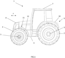
- a tractor 1 has a rear wheels 2 mounted to a rear axle 3, steerable front wheels 4 mounted to a front axle 5, and a frame or chassis 6 supported on the axles 3, 5.
- a user cab 7 is mounted to the frame 6 and an engine compartment 8 containing an IC engine or other prime mover is located in front of the cab 7.
- Rear mudguard assemblies 9 each have a rear mudguard 10 mounted to the vehicle to partially encircle an outer periphery of a respective one of the rear wheels 2 and front mudguard assemblies 11 each have a front mudguard 12 mounted to the vehicle to partially encircle an outer periphery of a respective one of the front wheels 4. Only one rear mudguard assembly 9 and one front mudguard assembly 11 are shown in FIG.1 but it will be appreciated that corresponding mudguard assemblies are provided for the wheels on the opposite side of the tractor.
- the front mudguard assemblies 11 are configured in accordance with an aspect of the invention. Embodiments of which will now be described with reference to FIGs. 2 to 9 .
- Each front mudguard assembly 11 includes a mudguard 12 and a support 13 which mounts the mudguard 12 to a structural component of the vehicle 1.
- the mudguard 12 is positioned so that it partially encircles an upper circumferential extent of one of the front wheels 4.
- the support 13 may be mounted to a casing of the front axle 5 at a position adjacent to the wheel 4. This has the advantage that the mudguard 12 moves with the axle 5 so as to maintain a desired clearance between the mudguard 12 and the wheel 4 as the axle 5 moves relative to the frame 6.
- the support 13 can be attached to any other suitable structural component of the vehicle 1 such as the frame 6 or a component mounted to the frame, depending on the overall structure of the vehicle.
- Each mudguard 12 has a main body member 14 which is elongate and curved in a longitudinal direction (which in use aligns generally to a fore and aft direction of the vehicle 1 as indicated by arrow A in FIG. 1 ) so as to partially encircle a circumferential extent of the wheel 4.
- the main body member 14 is operative in use to reduce the spray of mud, dirt, water, and other elements from the wheel 4 when the vehicle is moving.
- the main body member 14 has a lower surface 15 which in use is directed toward the wheel 4 and an upper surface 16 which in use is directed away from the wheel.
- the main body member 14 has a mounting region 17 which defines a recess 18 that opens at the lower surface 15 in a downwardly facing direction in use.
- each mudguard 12 also includes an initially separate cover member 19 mounted about the mounting region 17 on the upper surface 16 of the main body member.
- the cover member 19 can be omitted.
- the main body 14 member can be made of any suitable material by any suitable method but in an embodiment is moulded from one or more polymeric materials, such as high density poly ethylene (HD-PE), for example.
- the cover member 19 can also be can be made of any suitable material by any suitable method but in an embodiment is moulded from one or more polymeric materials such as Polydicyclopentadiene (PDCPD), for example.
- the cover member 19 may be provided in a colour which is different from that of the main body member 14.
- the colour of the cover member 19 could be coordinated with the colour scheme of the vehicle as a whole.
- the cover member 19 could, for example, be the same colour as parts of the body work of the cab 7 or a contrasting colour.
- the colour of the cover member 19 could be adapted to form part of the branding or "get up" of the vehicle manufacturer.
- the mounting region 17 and recess 18 are generally U-shaped in plan, having a central region 17a, 18a which extends generally in the longitudinal direction of the main body member and a lateral region 17b, 18b at either end of the longitudinal region 17a, 18a which each extend generally in a lateral direction from the longitudinal region 17a, 18a to a first longitudinal side edge 20a of the main body member.
- the longitudinal region 17a, 18a may be located beyond a longitudinal centre line of the main body from first longitudinal side 20a so as to be closer to an opposing, second longitudinal side edge 20b.
- the lateral regions 17b, 18b do not extend perpendicularly relative to the longitudinal region 17a, 18a or parallel to one another but are angled away from each other by a limited extent in a direction towards the first longitudinal side edge 20a.
- the precise shape of the mounting region 17 and recess 18 can be varied depending on the particular requirements of any given vehicle.
- the support 13 is a largely tubular structure which includes a first part 21 mounted to the front axle 5 and a second part 22 which supports the mudguard and which is releasably attachable to the first part 21.
- the first part 21 includes a first tubular attachment portion 21a which is configured to extend generally upright in use and a vehicle mounting portion 21b with a mounting bracket 21c.
- the mounting bracket 21c has apertures 23 for receiving releasable fasteners, e.g. bolts or screws or the like, to secure the first part 21 to the axel casing. Other arrangements for releasably securing the first part 21 to the axle 5 can be adopted.
- the second part 22 has a second tubular attachment portion 22a and a tubular mudguard mounting portion 22b.
- the second tubular attachment portion 22a is configured to extend generally upright coaxially with the first tubular attachment portion 21a in use.
- the mudguard mounting portion 22b is angled relative to the second tubular attachment portion 22a and includes a lateral section 24 which is received in one of the lateral regions 18b of the recess 18 in the mudguard mounting region 17 and a longitudinal section 25 which is received in the longitudinal region 18a of the recess.
- the lateral section 24 is aligned to extend generally horizontally above the wheel 4 whilst the longitudinal section 25 is inclined downwardly and rearward from the lateral section 24 so that the main body member 14 of the mudguard is held so as to extend in close proximity about an upper and rearward portion of the outer circumference of the wheel 4.
- This configuration is particularly suited to mounting mudguards for the front wheels 4 of a vehicle 1.
- the shape and inclination of the various sections of the mudguard mounting portion 22a can be adapted depending on the required shape and configuration of the mudguard and might be different for use with a rear wheel.
- the mudguard mounting portion 22a of the second part 22 of the support 13 is mainly located within the recess 18, which is offset upwardly from the lower, inner surface 15 of the majority of the of the main body member 14.
- this enables the lower, inner surface 15 of the majority of the main body member 14 to be positioned closer to the outer circumference of the wheel 4 than would be possible if the mounting portion 22b were located below the lower, inner surface 15, as in a conventional mudguard arrangement.
- the height at which the second tubular attachment portion 22a is secured to the first tubular attachment portion 21a is adjustable to enable adjustment of the height of the mudguard 12 relative to the wheel 4. To this end, and as seen best in FIG.
- the first tubular attachment portion 21a and the second tubular attachment portion 22a are telescopically mounted to each other.
- a part of the second tubular attachment portion 22a is a close sliding fit over at part of the first attachment portion 21a.
- An array of holes 26 arranged in diametrically opposed sets or pairs at different heights are provided in the telescopic part of the first attachment portion 21a.
- a corresponding pair of diametrically opposed holes 27 are provided in the second attachment portion 22a where it fits over the telescopic part of the first attachment portion 21.
- the holes 27 in the second attachment portion can be aligned with any one of the sets of holes 26 in the first attachment portion and a cotter pin 28 inserted through the holes 27 in the second attachment portion passing through the aligned set of holes 26 in the first attachment portion to secure the second attachment portion 22a to the first attachment portion 21a at a desired height.
- the cotter pin 28 is secured in place with a spring safety clip 29 in a known manner. Only two sets of holes 26 in the first attachment portion 21a are visible in FIG. 5 but it will be appreciated that there is at least one further set located where the cotter pin 28 is shown.
- the height of the mudguard 12 relative to the wheel 4 can be adjusted by attaching the second attachment portion 22a using different sets of holes 26 in the first attachment portion 21a.
- the first and second attachment portions 21a, 22a are a close sliding fit so that the two are firmly secured together without excessive movement of the second attachment portion 22a relative to the first 21a once the cotter pin 28 is in place.
- the second attachment portion 22a could be received within the first tubular attachment portion 21a and that an arrangement other than a cotter pin 28 can be used to secure the two parts together.
- a clamping arrangement could be used or a fastener such as a nut and bolt used in place of the cotter pin 28.
- Other arrangements to enable the first and second attachment portions 21a, 22a to be adjustably coupled together to vary the height of the mudguard 12 can be adopted as will be apparent to those skilled in the art.
- the mounting portion 22b is located in the recess 18, with the lateral section 24 located in one of the lateral portions 18b and the longitudinal section 25 extending over half way along the longitudinal portion 18a.
- the mounting portion 22b is secured in position using a number of brackets 30. In the present embodiment there are three brackets 30 but more or fewer than three brackets could be used.
- Each bracket 30 is in the form of a curved band with a tab 31 at either end.
- the bracket 30 partially encircles the tubular mounting portion 22b and each tab 31 aligns with a respective lug 32 in the main body member.
- Aligned apertures 31a, 32a extend though each tab 31 and lug 32 through which the threaded shaft of a releasable fastener 33 (e.g. a screw or bolt or the like) is inserted.
- a releasable fastener 33 e.g. a screw or bolt or the like
- the cover member is provided with fastener formations 34 which align with respective lugs 32 and which include an internally treaded aperture 35 in which the shaft of the releasable fastener 33 is received.
- Each fastener 33 has a head which locates adjacent the tab 31 such that when the fasteners are tightened, the main body 14 of the mudguard is clamped between the bracket 30 and the cover member 19.
- the threaded apertures 35 may be formed directly the cover member 19 or fastening members, such as captive nuts or the like, may attached to the fastener formations 34 to define the threaded apertures 35.
- the apertures 32a of lugs 32 of the main body member 14 are threaded and the fasteners 33 are screwed into the lugs 32.
- the threads in apertures 32a may be formed in the body member 14 itself or by fastening members, such as captive nuts or the like, secured in each aperture 32a to define the threads.
- the methods of attaching the mudguard 12 to the mudguard mounting portion 22b described above have the advantage that no fasteners are visible from above the mudguard.
- the main body member 14 is predominantly a relatively thin, curved, panel or sheet-like structure.
- the mounting region 17, which comprises a raised or embossed elongate channel-like formation having opposed side walls 17c, 17d and an upper wall 17e, helps to provide the main body member 14 with structural rigidity so that it does not rely on the support 13 to hold its shape.
- Each of the braces 40 are profiled to define a recess 41 in which the mudguard mounting portion 22b of the second part 22 of the support 13 is received.
- the braces not only increase the structural rigidity of the main body member 14 but also help to support the mudguard mounting portion 22b of the support 13.
- the main body member 14 may be profiled to define a number of other stiffening features which provide structural rigidity.
- the main body member 14 may have a downwardly projecting side wall region 42, 43 extending along either longitudinal side edge 20a, 20b.
- the mounting region 17 projects beyond the side wall region 42 at either end and is partially closed by an outer brace 40a.
- the cover member 19 may extend over the projecting end sections of the mounting region 17 and may be profiled to engage the outer surface of the side wall region 42. This also helps to increase the structural rigidity of the main body member 14 when assembled.
- the main body member 14 is also profiled to define at least one stiffening ridge 44 which surrounds the mounting formation 17 on the outer side thereof.
- the number and type of stiffening formations provided in the main body member 14 can be varied from those described above. However, it is preferred that the main body member 14 itself has sufficient structural integrity that it is not reliant on external support to hold its shape in use, beyond location of the mudguard mounting portion 22b in the recess 18.
- the first part 21 of the support 13 will be mounted to the axle 4 separately from the second part 22 of the support and that the mudguard 12, including the main body member 14 and the cover member 19 (where present), will be attached to the second part 22 of the support 13.
- the two parts 21, 22 of the support can then be coupled together at the correct height.
- the first and second parts 21, 22 of the support 13 can be separated to provide access to the fasteners 33 securing the mudguard to the mudguard mounting portion 22b.
- the main body member 14 and the cover 19 may be arranged to be symmetrical about a line of symmetry X (i.e. a mirror line) which extends laterally across the main body member 14 at a position half-way along its length.
- a line of symmetry X i.e. a mirror line
- the lateral section 24 of the mudguard mounting portion 22b locates in a first one of the lateral portions 18b of the recess 18 and when used on the other side of the vehicle it locates in the other of the lateral portions 18b.
- the first part 21 of the support 13 is also configured so that it can be used on either side of the vehicle.
- the only part of the mudguard assembly 11 which is handed is the second part 22 of the support 13.
- this is a tubular structure, as is the case in this embodiment, it is relatively easy and cheap to manufacture.
- the provision of a mudguard assembly 11 in which a majority of the components can be fitted to either side of a vehicle helps to reduce manufacturing costs and means that the vehicle manufacturer (and/or a supplier of the mudguard assembly) have a reduced inventory of parts that must be stored.
- FIG. 9 illustrates a modification in which extension members 45 are moulded onto the main body member 14.
- similar extension members 45 are moulded to each end of the main body member 14 so that the resulting combination remains symmetrical about line of symmetry X and can be used on either side of a vehicle.
- only one extension member 45 may be moulded or the extension members at either end may be different.
- the extension members 45 may be of a different material to the main body member 14 and could, for example, be moulded from rubber (synthetic or natural) or other elastomeric materials whilst the main body member 14 is moulded from one or more polymeric (plastics) materials.
- a double injection moulding technique (also referred to as two-shot injection or 2k moulding) can be used to mould extension members 45 to the main body member 14.
- the addition of one or more extension members 45 extends the length of the mudguard 12 making it suitable for use on a larger vehicle and/or provides additional coverage of the wheel 4.
- the same moulding tools can be used to produce a mudguards of different lengths suitable for a range of vehicles and applications, some with two extension members 45, some with only one extension member 45 at one end, and some with no extension members.
- one or more extension members 45 can be mechanically attached to the main body member 14.
- the one or more extension members 45 could be secured in position using fasteners, which may be releasable (e.g. a nut and bolt).
Landscapes
- Engineering & Computer Science (AREA)
- Chemical & Material Sciences (AREA)
- Combustion & Propulsion (AREA)
- Transportation (AREA)
- Mechanical Engineering (AREA)
- Body Structure For Vehicles (AREA)
Abstract
Description
- Embodiments of the present disclosure relate generally to a mudguard assembly for a vehicle, especially an agricultural vehicle such as an agricultural tractor.
- Mudguards are provided for the wheels of agricultural vehicles such as tractors to reduce the spray of mud and other elements from the wheels as the vehicle moves. A typical mudguard assembly includes a mudguard or fender which forms a cover surrounding a part of a wheel and a supporting structure to hold the mudguard in position. In a simple arrangement, the mudguard is moulded from polymeric material and takes the form of a relatively thin, panel-like member which is curved or otherwise shaped to follow the outer circumference of the wheel. Often, a supporting structure has a frame portion which extends over a large area of the mudguard to provide structural support for the mudguard which is otherwise too flexible to hold its shape in use. This is problematic as it requires a complex supporting structure which is expensive to manufacture and difficult to assemble. It also has the effect of increasing the spacing between a lower surface of the mudguard and the wheel, reducing the effectiveness of the mudguard and potentially reducing the field of vision of the driver. A further drawback of known mudguard assemblies is that different mudguards and/or supporting structures are often required for use on either side of the vehicle. This leads to increased manufacturing costs and component inventory for the vehicle manufacturer and/or supplier.
- Aspects of the invention are directed to a mudguard assembly for a vehicle, especially an agricultural vehicle such as a tractor, and to a vehicle having such a mudguard assembly.
- According to an aspect of the invention, there is provided a moulded mudguard and a tubular support for mounting the mudguard to a vehicle and where a mudguard mounting portion of the tubular support is received within a recess defined in the moulded mudguard. The recess may include at least a portion extending in a longitudinal direction of the moulded mudguard and at least one lateral portion that extends from an end of the longitudinal portion to a first longitudinal side edge of the moulded mudguard.
- According to a further aspect of the invention, there is provided a mudguard assembly for a vehicle, the mudguard assembly comprising a mudguard and a support for mounting the mudguard to a structural component of the vehicle, the support comprising a mudguard mounting portion to which the mudguard is mounted; the mudguard comprising an elongate main body member having a longitudinal direction, the main body member being shaped in the longitudinal direction for extending over a wheel of the vehicle, the main body member having a lower surface which in use is directed toward the wheel and upper surface which in use is directed away from the wheel, the main body member being profiled to define a mounting region including a recess with a downwardly facing opening in which at least part of the mudguard mounting portion is located, wherein the mounting region projects outwardly beyond the upper surface of the main body member proximal to the mounting region.
- Defining the recess for the mudguard mounting portion in a raised mounting region of the main body member enables a lower surface of the main body member to be positioned closer to the wheel, making the mudguard more effective at preventing spray. Profiling of the main body member to define the mounting portion provides the main body member with structural rigidity so that it is less dependent on the support to retain its shape in use. This enables a simpler supporting structure to be adopted.
- The main body member may be curved in the longitudinal direction.
- The main body member may be a sheet like member which is profiled to define the mounting region in the form of a raised or embossed channel-like formation.
- The mudguard assembly may be e configured such that the mudguard mounting portion of the tubular support is wholly located above the lower surface of the main body of the mudguard when assembled.
- The recess may have a longitudinal portion which extends generally in the longitudinal direction of the main body member and at least one lateral portion that extends from an end of the longitudinal portion to a first longitudinal side edge of the main body member. The mudguard mounting portion may have a longitudinal section located in the longitudinal portion of the recess and a lateral section angled relative to the longitudinal section and located in the lateral portion of the recess. The recess may have two lateral portions, each lateral portion extending from a respective end of the longitudinal portion to the first longitudinal side edge of the main body member.
- By forming the recess with two lateral portions, the main body member can be used on either side of the vehicle. The lateral section of the support locates in one of the lateral portions when the main body member is positioned for use with a wheel on a first side of the vehicle and locates in the other of the lateral portions when the main body member is positioned for use with a wheel on the other side of the vehicle. Advantageously, the main body member is symmetrically about a line of symmetry (i.e. a mirror line) extending laterally at the longitudinal mid-point of the main body member.
- The main body member may define a respective downwardly projecting side wall region extending along each of the first and a second longitudinal side edge and at least one aperture may be defined in the side wall region at the first longitudinal side edge, the aperture opening into the at least one lateral portion of the recess and through which the lateral section of the mounting portion passes. Where the recess has two lateral portions, a respective aperture may be provided in the side wall region at the first longitudinal side edge in alignment with each of the lateral portions of the recess.
- The mounting region may comprise first and second opposed side walls and an upper wall which define the recess between them. At least one brace may extend across the recess between the first and second side walls. The at least one brace may define a recess for receiving the mudguard mounting portion. There may be a plurality of braces. The mounting region may project beyond the side wall region of the main body member at the first longitudinal side edge.
- The support may comprises a telescopically adjustable mechanism configured to enable the height of the mudguard to be adjusted.
- The support may comprise a first part for attachment to the structural component and a second part including the mudguard mounting portion which is releasably attachable to the first part. The first part of the support may include a first attachment portion configured to extend generally upright in use, and the second part of the support may have a corresponding second attachment portion which is angled relative to the mudguard mounting portion and configured to be releasably attachable to the first attachment portion. The mudguard assembly may comprise an attachment system for securing the second attachment portion to the first attachment portion. The attachment system may be configured to enable the height at which the second attachment position is secured relative to the first attachment position to be adjusted. A part of one of the first and second attachment portions may be telescopically located within a part of the other of the first and second attachment portions. Said one of the first and second attachment portions may be provided with an array of first mounting apertures arranged in diametrically opposed sets (e.g. pairs) at different heights. The other of the first and second attachment portions may be provided with a pair of diametrically opposed second mounting apertures which are configured to be aligned with any one of the sets of first mounting apertures. The mudguard assembly may have a cotter pin or other fastener which is configured to be inserted through aligned first and second mounting apertures to secure the first and second attachment portions together.
- The support may be configured to enable the height at which the mudguard is held above the structural component to be adjusted.
- The structural component may be an axle and may be a front axle.
- The second attachment portion may be angled in the region of 80 to 100 degrees, and more particularly in the region of 85-95 degrees, relative to the mudguard mounting portion. The arrangement may be configured such that in use, at least the lateral section of the mudguard mounting portion is aligned generally horizontally. The longitudinal section of the mudguard mounting portion may be configured so as to inclined downwardly and rearward from the lateral section in use.
- The second part of the support and at least the first attachment portion of the first part of the support may be tubular structures.
- The main body member may be profiled to define features which provide structural rigidity. The main body member may be profiled to define at least one stiffening ridge.
- The mudguard may include a cover member mounted about an upper surface of the mounting region of the main body member. Where the main body member is symmetrical about a line of symmetry extending laterally at the longitudinal mid-point of the main body member, the cover member may also be symmetrical about a line of symmetry extending laterally at the longitudinal mid-point of the cover member and which is coincident with the line of symmetry of the main body member. The mudguard may be attached to the mudguard mounting portion of the support by means of brackets secured to the mudguard by releasable fasteners. The releasable fasteners may be threaded fasteners, such as bolts or screws. The threaded fasteners may engage in respective threaded apertures provided in the main body member. Where the mudguard has a cover member, the threaded fasteners may pass through corresponding apertures in the main body member and engage in respective threaded apertures provided in the cover member.
- At least one extension member may be provided at one end the main body member. An extension member may be provided at each end the main body member. The at least one extension member may be made from a material different from that used to form the main body member. The extension member may be formed from a rubber material and the main body member may be formed from a plastics material. The main body member and the at least one extension member may be manufactured using a double-injection moulding technique.
- In accordance with a further aspect of the invention, there is provided a mudguard for use in a mudguard assembly as set out in either of the above aspects of the invention, wherein the mudguard comprises an elongate main body member having a longitudinal direction and which is shaped (e.g. curved) in the longitudinal direction for extending over a wheel of a vehicle, the main body member having a lower surface which in use is directed toward the wheel and an upper surface which in use is directed away from the wheel, the main body member having a mounting region which defines a recess with a downwardly facing opening, wherein the mounting region projects outwardly above the upper surface of the main body member proximal to the mounting region.
- The mounting region may be a raised or embossed channel-like formation defined by the main body member.
- The recess may have a longitudinal portion which extends generally in the longitudinal direction of the mudguard and at least one lateral portion that extends from an end of the longitudinal portion to a first longitudinal side edge of the main body member. The recess may have two lateral portions, each lateral portion extending from a respective end of the longitudinal portion to the first longitudinal side edge of the main body member.
- The main body member may define a respective downwardly projecting side wall region extending along each of the first and a second longitudinal side edge, at least one aperture being defined in the side wall region at the first longitudinal side edge of the main body member, the aperture opening into the at least one lateral portion of the recess. Where the recess has two lateral portions, a respective aperture may be provided in the side wall region in alignment with each of the lateral portions of the recess.
- The main body member may be profiled to define at least one further feature which provides structural rigidity. The main body member may be profiled to define at least one stiffening ridge.
- The mudguard may include a cover member mounted about the upper surface of the mounting region.
- At least one extension member may be provided at one end the main body member. An extension member may be provided at each end the main body member. The at least one extension member may be made from a material different from that used to form the main body member. The extension member may be formed from a rubber material and the main body member may be formed from a plastics material. The main body member and the at least one extension may be manufactured using a double-injection moulding technique.
- In accordance with a still further aspect of the invention, there is provided a vehicle comprising a mudguard assembly or a mudguard according to any of the aspects set out above. The vehicle may be an agricultural vehicle and may be a tractor.
- One or more embodiments of the invention will now be described, by way of example only, with reference to the accompanying drawings, in which:
-
FIG. 1 is a simplified side view of a tractor having a mudguard assembly according to an aspect of the invention; -
FIG. 2 is a perspective view of a mudguard assembly according to an aspect of the invention which forms part of the vehicle ofFIG. 1 ; -
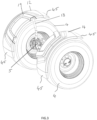
FIG. 3 is a perspective view of a front axle assembly of the vehicle ofFIG. 1 to which a pair of the mudguard assembles ofFIG. 2 are mounted; -
FIG. 4 is a longitudinal cross sectional view through the mudguard assembly ofFIG.2 ; -
FIG. 5 is a perspective view of part of the mudguard assembly ofFIG.2 illustrating an arrangement for adjusting the height of the mudguard; -
FIG. 6 is a perspective view from below of the mudguard assembly ofFIG. 2 ; -
FIG. 7 is an exploded, perspective view from below of part of the mudguard assembly ofFIG. 2 , illustrating an arrangement for securing a mudguard to a support; -
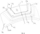
FIG. 8 is a perspective view from above of a main body member forming part of the mudguard assembly ofFIG. 2 ; and -
FIG. 9 is a perspective view of a modified embodiment of the mudguard assembly ofFIG. 2 in which extensions are moulded to a main body member of the mudguard. - Embodiments of the present disclosure will now be described with reference to an agricultural vehicle in the form of an
agricultural tractor 1, as illustrated schematically inFIG. 1 . However, mudguards and mudguard assemblies according to aspects of the present invention can be adapted for use with other types of vehicle including other types of agricultural vehicle or mobile machine such as harvesters and the like. - With reference to
FIG. 1 , atractor 1 has arear wheels 2 mounted to arear axle 3, steerablefront wheels 4 mounted to afront axle 5, and a frame orchassis 6 supported on theaxles user cab 7 is mounted to theframe 6 and anengine compartment 8 containing an IC engine or other prime mover is located in front of thecab 7.Rear mudguard assemblies 9 each have arear mudguard 10 mounted to the vehicle to partially encircle an outer periphery of a respective one of therear wheels 2 andfront mudguard assemblies 11 each have afront mudguard 12 mounted to the vehicle to partially encircle an outer periphery of a respective one of thefront wheels 4. Only onerear mudguard assembly 9 and onefront mudguard assembly 11 are shown inFIG.1 but it will be appreciated that corresponding mudguard assemblies are provided for the wheels on the opposite side of the tractor. - The
front mudguard assemblies 11 are configured in accordance with an aspect of the invention. Embodiments of which will now be described with reference toFIGs. 2 to 9 . - Each
front mudguard assembly 11 includes amudguard 12 and asupport 13 which mounts themudguard 12 to a structural component of thevehicle 1. In use, themudguard 12 is positioned so that it partially encircles an upper circumferential extent of one of thefront wheels 4. As illustrated inFIG. 3 , thesupport 13 may be mounted to a casing of thefront axle 5 at a position adjacent to thewheel 4. This has the advantage that themudguard 12 moves with theaxle 5 so as to maintain a desired clearance between themudguard 12 and thewheel 4 as theaxle 5 moves relative to theframe 6. However, thesupport 13 can be attached to any other suitable structural component of thevehicle 1 such as theframe 6 or a component mounted to the frame, depending on the overall structure of the vehicle. - Each
mudguard 12 has amain body member 14 which is elongate and curved in a longitudinal direction (which in use aligns generally to a fore and aft direction of thevehicle 1 as indicated by arrow A inFIG. 1 ) so as to partially encircle a circumferential extent of thewheel 4. Themain body member 14 is operative in use to reduce the spray of mud, dirt, water, and other elements from thewheel 4 when the vehicle is moving. Themain body member 14 has alower surface 15 which in use is directed toward thewheel 4 and anupper surface 16 which in use is directed away from the wheel. Themain body member 14 has a mountingregion 17 which defines arecess 18 that opens at thelower surface 15 in a downwardly facing direction in use. In the illustrated embodiment, eachmudguard 12 also includes an initiallyseparate cover member 19 mounted about the mountingregion 17 on theupper surface 16 of the main body member. However, in other embodiments, thecover member 19 can be omitted. Themain body 14 member can be made of any suitable material by any suitable method but in an embodiment is moulded from one or more polymeric materials, such as high density poly ethylene (HD-PE), for example. Thecover member 19 can also be can be made of any suitable material by any suitable method but in an embodiment is moulded from one or more polymeric materials such as Polydicyclopentadiene (PDCPD), for example. Thecover member 19 may be provided in a colour which is different from that of themain body member 14. The colour of thecover member 19 could be coordinated with the colour scheme of the vehicle as a whole. Thecover member 19 could, for example, be the same colour as parts of the body work of thecab 7 or a contrasting colour. The colour of thecover member 19 could be adapted to form part of the branding or "get up" of the vehicle manufacturer. - The mounting
region 17 andrecess 18 are generally U-shaped in plan, having a central region 17a, 18a which extends generally in the longitudinal direction of the main body member and a lateral region 17b, 18b at either end of the longitudinal region 17a, 18a which each extend generally in a lateral direction from the longitudinal region 17a, 18a to a firstlongitudinal side edge 20a of the main body member. The longitudinal region 17a, 18a may be located beyond a longitudinal centre line of the main body from firstlongitudinal side 20a so as to be closer to an opposing, second longitudinal side edge 20b. In the embodiment as illustrated, the lateral regions 17b, 18b do not extend perpendicularly relative to the longitudinal region 17a, 18a or parallel to one another but are angled away from each other by a limited extent in a direction towards the firstlongitudinal side edge 20a. However, the precise shape of the mountingregion 17 andrecess 18 can be varied depending on the particular requirements of any given vehicle. - The
support 13 is a largely tubular structure which includes afirst part 21 mounted to thefront axle 5 and asecond part 22 which supports the mudguard and which is releasably attachable to thefirst part 21. Thefirst part 21 includes a firsttubular attachment portion 21a which is configured to extend generally upright in use and a vehicle mounting portion 21b with a mountingbracket 21c. The mountingbracket 21c hasapertures 23 for receiving releasable fasteners, e.g. bolts or screws or the like, to secure thefirst part 21 to the axel casing. Other arrangements for releasably securing thefirst part 21 to theaxle 5 can be adopted. - The
second part 22 has a secondtubular attachment portion 22a and a tubular mudguard mounting portion 22b. The secondtubular attachment portion 22a is configured to extend generally upright coaxially with the firsttubular attachment portion 21a in use. The mudguard mounting portion 22b is angled relative to the secondtubular attachment portion 22a and includes alateral section 24 which is received in one of the lateral regions 18b of therecess 18 in themudguard mounting region 17 and alongitudinal section 25 which is received in the longitudinal region 18a of the recess. In use, thelateral section 24 is aligned to extend generally horizontally above thewheel 4 whilst thelongitudinal section 25 is inclined downwardly and rearward from thelateral section 24 so that themain body member 14 of the mudguard is held so as to extend in close proximity about an upper and rearward portion of the outer circumference of thewheel 4. This configuration is particularly suited to mounting mudguards for thefront wheels 4 of avehicle 1. However, it will be appreciated that the shape and inclination of the various sections of themudguard mounting portion 22a can be adapted depending on the required shape and configuration of the mudguard and might be different for use with a rear wheel. - As can be seen best in
FIG. 4 , themudguard mounting portion 22a of thesecond part 22 of thesupport 13 is mainly located within therecess 18, which is offset upwardly from the lower,inner surface 15 of the majority of the of themain body member 14. Advantageously, this enables the lower,inner surface 15 of the majority of themain body member 14 to be positioned closer to the outer circumference of thewheel 4 than would be possible if the mounting portion 22b were located below the lower,inner surface 15, as in a conventional mudguard arrangement. The height at which the secondtubular attachment portion 22a is secured to the firsttubular attachment portion 21a is adjustable to enable adjustment of the height of themudguard 12 relative to thewheel 4. To this end, and as seen best inFIG. 5 , the firsttubular attachment portion 21a and the secondtubular attachment portion 22a are telescopically mounted to each other. In the present case, a part of the secondtubular attachment portion 22a is a close sliding fit over at part of thefirst attachment portion 21a. An array ofholes 26 arranged in diametrically opposed sets or pairs at different heights are provided in the telescopic part of thefirst attachment portion 21a. A corresponding pair of diametricallyopposed holes 27 are provided in thesecond attachment portion 22a where it fits over the telescopic part of thefirst attachment portion 21. Theholes 27 in the second attachment portion can be aligned with any one of the sets ofholes 26 in the first attachment portion and a cotter pin 28 inserted through theholes 27 in the second attachment portion passing through the aligned set ofholes 26 in the first attachment portion to secure thesecond attachment portion 22a to thefirst attachment portion 21a at a desired height. The cotter pin 28 is secured in place with aspring safety clip 29 in a known manner. Only two sets ofholes 26 in thefirst attachment portion 21a are visible inFIG. 5 but it will be appreciated that there is at least one further set located where the cotter pin 28 is shown. The height of themudguard 12 relative to thewheel 4 can be adjusted by attaching thesecond attachment portion 22a using different sets ofholes 26 in thefirst attachment portion 21a. The first andsecond attachment portions second attachment portion 22a relative to the first 21a once the cotter pin 28 is in place. It will be appreciated that in an alternative arrangement thesecond attachment portion 22a could be received within the firsttubular attachment portion 21a and that an arrangement other than a cotter pin 28 can be used to secure the two parts together. For example, a clamping arrangement could be used or a fastener such as a nut and bolt used in place of the cotter pin 28. Other arrangements to enable the first andsecond attachment portions mudguard 12 can be adopted as will be apparent to those skilled in the art. - Attachment of the
mudguard 12 to the mudguard mounting portion 22b of thesecond part 22 of thesupport 13 will be described with reference toFIGs 6 and7 . The mounting portion 22b is located in therecess 18, with thelateral section 24 located in one of the lateral portions 18b and thelongitudinal section 25 extending over half way along the longitudinal portion 18a. The mounting portion 22b is secured in position using a number ofbrackets 30. In the present embodiment there are threebrackets 30 but more or fewer than three brackets could be used. Eachbracket 30 is in the form of a curved band with atab 31 at either end. Thebracket 30 partially encircles the tubular mounting portion 22b and eachtab 31 aligns with arespective lug 32 in the main body member. Aligned apertures 31a, 32a extend though eachtab 31 and lug 32 through which the threaded shaft of a releasable fastener 33 (e.g. a screw or bolt or the like) is inserted. Where themudguard 12 has acover member 19, the cover member is provided withfastener formations 34 which align withrespective lugs 32 and which include an internally treaded aperture 35 in which the shaft of thereleasable fastener 33 is received. Eachfastener 33 has a head which locates adjacent thetab 31 such that when the fasteners are tightened, themain body 14 of the mudguard is clamped between thebracket 30 and thecover member 19. When all thefasteners 33 securing the threebrackets 30 are engaged and tightened, themain body member 14 is firmly clamped to the mounting portion 22b. The threaded apertures 35 may be formed directly thecover member 19 or fastening members, such as captive nuts or the like, may attached to thefastener formations 34 to define the threaded apertures 35. In an alternative embodiment, especially where nocover member 19 is provided, the apertures 32a oflugs 32 of themain body member 14 are threaded and thefasteners 33 are screwed into thelugs 32. The threads in apertures 32a may be formed in thebody member 14 itself or by fastening members, such as captive nuts or the like, secured in each aperture 32a to define the threads. - The methods of attaching the
mudguard 12 to the mudguard mounting portion 22b described above have the advantage that no fasteners are visible from above the mudguard. - The
main body member 14 is predominantly a relatively thin, curved, panel or sheet-like structure. However, the mountingregion 17, which comprises a raised or embossed elongate channel-like formation having opposedside walls 17c, 17d and an upper wall 17e, helps to provide themain body member 14 with structural rigidity so that it does not rely on thesupport 13 to hold its shape. To provide further structural rigidity, there are a number ofbraces 40 which extend internally across therecess 18 from one side wall 17c of the channel-like member to the other 17d and are also attached to the upper wall 17e. Each of thebraces 40 are profiled to define arecess 41 in which the mudguard mounting portion 22b of thesecond part 22 of thesupport 13 is received. The braces not only increase the structural rigidity of themain body member 14 but also help to support the mudguard mounting portion 22b of thesupport 13. In an embodiment, themain body member 14 may be profiled to define a number of other stiffening features which provide structural rigidity. For example, themain body member 14 may have a downwardly projectingside wall region longitudinal side edge 20a, 20b. At the firstlongitude side edge 20a, the mountingregion 17 projects beyond theside wall region 42 at either end and is partially closed by anouter brace 40a. Thecover member 19 may extend over the projecting end sections of the mountingregion 17 and may be profiled to engage the outer surface of theside wall region 42. This also helps to increase the structural rigidity of themain body member 14 when assembled. In an embodiment, themain body member 14 is also profiled to define at least onestiffening ridge 44 which surrounds the mountingformation 17 on the outer side thereof. The number and type of stiffening formations provided in themain body member 14 can be varied from those described above. However, it is preferred that themain body member 14 itself has sufficient structural integrity that it is not reliant on external support to hold its shape in use, beyond location of the mudguard mounting portion 22b in therecess 18. - For mounting the
mudguard assembly 11 to avehicle 1, it is expected that thefirst part 21 of thesupport 13 will be mounted to theaxle 4 separately from thesecond part 22 of the support and that themudguard 12, including themain body member 14 and the cover member 19 (where present), will be attached to thesecond part 22 of thesupport 13. The twoparts second parts support 13 can be separated to provide access to thefasteners 33 securing the mudguard to the mudguard mounting portion 22b. - The
main body member 14 and the cover 19 (where provided) may be arranged to be symmetrical about a line of symmetry X (i.e. a mirror line) which extends laterally across themain body member 14 at a position half-way along its length. This enables amain body member 14 andcover member 19 to be used on either side of avehicle 1. When amudguard 12 is used on one side of the vehicle, thelateral section 24 of the mudguard mounting portion 22b locates in a first one of the lateral portions 18b of therecess 18 and when used on the other side of the vehicle it locates in the other of the lateral portions 18b. Thefirst part 21 of thesupport 13 is also configured so that it can be used on either side of the vehicle. The only part of themudguard assembly 11 which is handed is thesecond part 22 of thesupport 13. However, where this is a tubular structure, as is the case in this embodiment, it is relatively easy and cheap to manufacture. Generally, it is preferable to produce differently shaped tubular mounting portions 22b rather than moulding differently shaped mudguards for use on either side of a vehicle. The provision of amudguard assembly 11 in which a majority of the components can be fitted to either side of a vehicle helps to reduce manufacturing costs and means that the vehicle manufacturer (and/or a supplier of the mudguard assembly) have a reduced inventory of parts that must be stored. -
FIG. 9 illustrates a modification in whichextension members 45 are moulded onto themain body member 14. In the embodiment as illustrated,similar extension members 45 are moulded to each end of themain body member 14 so that the resulting combination remains symmetrical about line of symmetry X and can be used on either side of a vehicle. However, in alterative embodiments, only oneextension member 45 may be moulded or the extension members at either end may be different. Theextension members 45 may be of a different material to themain body member 14 and could, for example, be moulded from rubber (synthetic or natural) or other elastomeric materials whilst themain body member 14 is moulded from one or more polymeric (plastics) materials. A double injection moulding technique (also referred to as two-shot injection or 2k moulding) can be used tomould extension members 45 to themain body member 14. The addition of one ormore extension members 45 extends the length of themudguard 12 making it suitable for use on a larger vehicle and/or provides additional coverage of thewheel 4. Thus the same moulding tools can be used to produce a mudguards of different lengths suitable for a range of vehicles and applications, some with twoextension members 45, some with only oneextension member 45 at one end, and some with no extension members. - Rather than being moulded onto the
main body member 14, one ormore extension members 45 can be mechanically attached to themain body member 14. In this embodiment, the one ormore extension members 45 could be secured in position using fasteners, which may be releasable (e.g. a nut and bolt). - Whilst aspects of the invention have been described with reference to embodiments of a mudguard assembly most suitable for a
front wheel 4 of a tractor, the principles can be adopted for use in producing a mudguard assembly for a rear wheel of atractor 1 or mudguard assemblies for use with other types of vehicle, especially agricultural vehicles. - While the present disclosure has been described herein with respect to certain illustrated embodiments, those of ordinary skill in the art will recognize and appreciate that it is not so limited. Rather, many additions, deletions, and modifications to the illustrated embodiments may be made without departing from the scope of the disclosure as hereinafter claimed, including legal equivalents thereof. In addition, features from one embodiment may be combined with features of another embodiment while still being encompassed within the scope as contemplated by the inventors. Further, embodiments of the disclosure have utility with different and various machine types and configurations.
Claims (15)
- A mudguard assembly (11) for a vehicle, the mudguard assembly comprising a mudguard (12) and a support (13) for mounting the mudguard to a structural component of the vehicle, the support comprising a mudguard mounting portion (22b) to which the mudguard is mounted; the mudguard comprising an elongate main body member (14) having a longitudinal direction, the main body member being shaped in the longitudinal direction for extending over a wheel of the vehicle, the main body member having a lower surface (15) which in use is directed toward the wheel and upper surface (16) which in use is directed away from the wheel, the main body member being profiled to define a mounting region (17) including a recess (18) with a downwardly facing opening in which at least part of the mudguard mounting portion (22b) is located, wherein the mounting region projects (17) outwardly beyond the upper surface (16) of the main body member proximal to the mounting region.
- A mudguard assembly as claimed in claim 1, where in the main body portion (14) is a sheet-like member profiled to define the mounting region (17) in the form of an embossed, channel-like formation.
- A mudguard assembly as claimed in claim 1 or claim 2, wherein the recess (18) has longitudinal portion (18a) which extends generally in the longitudinal direction of the main body member and at least one lateral portion (18b) that extends from an end of the longitudinal portion to a first longitudinal side edge (20a) of the main body member, the mudguard mounting portion (22b) having a longitudinal section (25) located in the longitudinal portion of the recess and a lateral section (24) angled relative to the longitudinal section and located in the lateral portion of the recess.
- A mudguard assembly as claimed in claim 3, wherein the recess (18) has two lateral portions (18b), each lateral portion extending from a respective end of the longitudinal portion (18a) to the first longitudinal side edge (20a) of the main body member.
- A mudguard assembly as claimed in anyone of the preceding claims, wherein the support (13) comprises a first part (21) for attachment to the structural component and a second part (22) including the mudguard mounting portion (22b), wherein the first part of the support includes a first attachment portion (21a) configured to extend generally upright in use, the second part (22) of the support having a corresponding second attachment portion (22a) angled relative to the mudguard mounting portion and configured to be releasably attachable to the first attachment portion.
- A mudguard assembly as claimed in claim 2 or claim 3, wherein the main body member (14) defines a respective downwardly projecting side wall region (42, 43) extending along each of the first and a second longitudinal side edge (20a, 20b), at least one aperture being defined in the side wall region at the first longitudinal side edge (20a), the aperture opening into the at least one lateral portion (18b) of the recess and through which the lateral section (24) of the mounting portion passes.
- A mudguard assembly as claimed in claim 6 when dependent on claim 3, wherein a respective aperture is provided in the side wall region (42) at the first longitudinal side edge (20a) in alignment with each of the lateral portions (18b) of the recess.
- A mudguard assembly as claimed in any one of the preceding claims, wherein the main body member (14) is profiled to define features (44) in addition to the mounting region (17) which are operative to provide structural rigidity.
- A mudguard assembly as claimed in any one of the preceding claims, wherein the mudguard (12) includes a cover member (19) mounted about an upper surface of the mounting region (17) of the main body member (14).
- A mudguard (12) for use in a mudguard assembly (11) as claimed in any one of the preceding claims, wherein the mudguard comprises an elongate main body member (140 having a longitudinal direction and which is curved in the longitudinal direction for extending over a wheel of a vehicle, the main body member having a lower surface (15) which in use is directed toward the wheel and an upper surface (16) which in use is directed away from the wheel, the main body member having a mounting region (17) which defines a recess (18) with a downwardly facing opening and wherein the mounting region projects outwardly above the upper surface (16) of the main body member proximal to the mounting region.
- A mudguard as claimed in claim 10, wherein the recess (18) has longitudinal portion (18a) which extends generally in the longitudinal direction of the mudguard and at least one lateral portion (18b) that extends from an end of the longitudinal portion to a first longitudinal side edge (20a)of the main body member.
- A mudguard assembly as claimed in claim 11, wherein the recess (18) has two lateral portions (18b), each lateral portion extending from a respective end of the longitudinal portion (18a)to the first longitudinal side edge (20a) of the main body member.
- A mudguard as claimed in claim 11 or claim 12, wherein the main body member (14) defines a respective downwardly projecting side wall region (42, 43) extending along each of the first and a second longitudinal side edge (20a, 20b), at least one aperture being defined in the side wall region (42) at the first longitudinal side edge (20a) of the main body member, the aperture opening into the at least one lateral portion (18b) of the recess.
- A mudguard as claimed in claim 13 when dependent on claim 12, wherein a respective aperture is provided in the side wall region (42) in alignment with each of the lateral portions (18b) of the recess.
- A mudguard assembly as claimed in any one of claims 10 to 14, wherein the main body member (14) is profiled to define features (44) which provide structural rigidity.
Applications Claiming Priority (1)
| Application Number | Priority Date | Filing Date | Title |
|---|---|---|---|
| GBGB2205529.7A GB202205529D0 (en) | 2022-04-14 | 2022-04-14 | Mudguard assembly |
Publications (2)
| Publication Number | Publication Date |
|---|---|
| EP4261108A1 true EP4261108A1 (en) | 2023-10-18 |
| EP4261108B1 EP4261108B1 (en) | 2024-07-17 |
Family
ID=81753182
Family Applications (1)
| Application Number | Title | Priority Date | Filing Date |
|---|---|---|---|
| EP23164302.4A Active EP4261108B1 (en) | 2022-04-14 | 2023-03-27 | Mudguard assembly |
Country Status (2)
| Country | Link |
|---|---|
| EP (1) | EP4261108B1 (en) |
| GB (1) | GB202205529D0 (en) |
Citations (4)
| Publication number | Priority date | Publication date | Assignee | Title |
|---|---|---|---|---|
| GB2151569A (en) * | 1983-12-07 | 1985-07-24 | Jacques Frederic Fichet | Mudguards for road vehicles |
| DE102004054692A1 (en) * | 2004-11-12 | 2006-06-08 | Deere & Company, Moline | Fender assembly for wheel of agricultural vehicle has strut which is connected with hub assembly and wheel which has wheel cover against which holding element rests and is connected adjustably in longitudinal direction of wheel cover |
| US20120080908A1 (en) * | 2010-10-01 | 2012-04-05 | Wellman Jason D | Fender mounting assembly |
| WO2017204715A1 (en) * | 2016-05-26 | 2017-11-30 | Scania Cv Ab | An attachment assembly for mounting a mudguard and a mudguard assembly |
-
2022
- 2022-04-14 GB GBGB2205529.7A patent/GB202205529D0/en not_active Ceased
-
2023
- 2023-03-27 EP EP23164302.4A patent/EP4261108B1/en active Active
Patent Citations (4)
| Publication number | Priority date | Publication date | Assignee | Title |
|---|---|---|---|---|
| GB2151569A (en) * | 1983-12-07 | 1985-07-24 | Jacques Frederic Fichet | Mudguards for road vehicles |
| DE102004054692A1 (en) * | 2004-11-12 | 2006-06-08 | Deere & Company, Moline | Fender assembly for wheel of agricultural vehicle has strut which is connected with hub assembly and wheel which has wheel cover against which holding element rests and is connected adjustably in longitudinal direction of wheel cover |
| US20120080908A1 (en) * | 2010-10-01 | 2012-04-05 | Wellman Jason D | Fender mounting assembly |
| WO2017204715A1 (en) * | 2016-05-26 | 2017-11-30 | Scania Cv Ab | An attachment assembly for mounting a mudguard and a mudguard assembly |
Also Published As
| Publication number | Publication date |
|---|---|
| GB202205529D0 (en) | 2022-06-01 |
| EP4261108B1 (en) | 2024-07-17 |
Similar Documents
| Publication | Publication Date | Title |
|---|---|---|
| US8066305B2 (en) | Adjustable fender | |
| CA1158282A (en) | Vehicle fender guard and support bar | |
| US8882121B2 (en) | Fender mounting assembly for utility vehicles | |
| US5769439A (en) | Universal running board accessory, preferably with fender attachment | |
| US6179311B1 (en) | Removable splash guard assembly for vehicles | |
| EP0786367B1 (en) | Vehicle with front side cooler arrangement | |
| US4740003A (en) | Vehicle quarter fender | |
| US4113278A (en) | Accessory kit and method for providing supplemental anti-sway control for automotive vehicles | |
| US7252170B2 (en) | Structure for disposing fuel tank for straddle-type vehicle | |
| US20080185810A1 (en) | Mudflap Assembly | |
| CA1285305C (en) | Vehicle quarter fender and assembly for mounting the same | |
| US6802517B1 (en) | Fender skirt and methods for using same | |
| EP3464032B1 (en) | An attachment assembly for mounting a mudguard and a mudguard assembly | |
| US4345307A (en) | Rectangular headlamp retainer | |
| US20190084622A1 (en) | Mud flap for attachment to a vehicle running board | |
| US5845983A (en) | Vehicle light mounting system | |
| US8864094B2 (en) | Fender mount for mirror | |
| EP4261108B1 (en) | Mudguard assembly | |
| DE102010007217A1 (en) | Assembly module for headlight of motor vehicle, comprises receiving recess for headlight housing, which is accessible in installation condition at motor vehicle from front, against direction of travel | |
| US12139205B2 (en) | Work vehicle | |
| US20230234494A1 (en) | Off-road vehicle | |
| US11235705B1 (en) | Rear-view mirror assembly | |
| US7469929B2 (en) | Bidirectionally and angularly adjustable fender attaching device | |
| JPH0534460Y2 (en) | ||
| KR100475955B1 (en) | Improved structure in assembling between mud guard and wheel guard of automobile |
Legal Events
| Date | Code | Title | Description |
|---|---|---|---|
| PUAI | Public reference made under article 153(3) epc to a published international application that has entered the european phase |
Free format text: ORIGINAL CODE: 0009012 |
|
| STAA | Information on the status of an ep patent application or granted ep patent |
Free format text: STATUS: THE APPLICATION HAS BEEN PUBLISHED |
|
| AK | Designated contracting states |
Kind code of ref document: A1 Designated state(s): AL AT BE BG CH CY CZ DE DK EE ES FI FR GB GR HR HU IE IS IT LI LT LU LV MC ME MK MT NL NO PL PT RO RS SE SI SK SM TR |
|
| STAA | Information on the status of an ep patent application or granted ep patent |
Free format text: STATUS: REQUEST FOR EXAMINATION WAS MADE |
|
| GRAJ | Information related to disapproval of communication of intention to grant by the applicant or resumption of examination proceedings by the epo deleted |
Free format text: ORIGINAL CODE: EPIDOSDIGR1 |
|
| STAA | Information on the status of an ep patent application or granted ep patent |
Free format text: STATUS: GRANT OF PATENT IS INTENDED |
|
| GRAP | Despatch of communication of intention to grant a patent |
Free format text: ORIGINAL CODE: EPIDOSNIGR1 |
|
| 17P | Request for examination filed |
Effective date: 20240418 |
|
| RBV | Designated contracting states (corrected) |
Designated state(s): AL AT BE BG CH CY CZ DE DK EE ES FI FR GB GR HR HU IE IS IT LI LT LU LV MC ME MK MT NL NO PL PT RO RS SE SI SK SM TR |
|
| RIC1 | Information provided on ipc code assigned before grant |
Ipc: B62D 25/16 20060101AFI20240502BHEP |
|
| GRAS | Grant fee paid |
Free format text: ORIGINAL CODE: EPIDOSNIGR3 |
|
| INTG | Intention to grant announced |
Effective date: 20240517 |
|
| RIN1 | Information on inventor provided before grant (corrected) |
Inventor name: HOKKANEN, HENRI |
|
| GRAA | (expected) grant |
Free format text: ORIGINAL CODE: 0009210 |
|
| STAA | Information on the status of an ep patent application or granted ep patent |
Free format text: STATUS: THE PATENT HAS BEEN GRANTED |
|
| AK | Designated contracting states |
Kind code of ref document: B1 Designated state(s): AL AT BE BG CH CY CZ DE DK EE ES FI FR GB GR HR HU IE IS IT LI LT LU LV MC ME MK MT NL NO PL PT RO RS SE SI SK SM TR |
|
| REG | Reference to a national code |
Ref country code: CH Ref legal event code: EP |
|
| REG | Reference to a national code |
Ref country code: DE Ref legal event code: R096 Ref document number: 602023000241 Country of ref document: DE |
|
| REG | Reference to a national code |
Ref country code: IE Ref legal event code: FG4D |
|
| REG | Reference to a national code |
Ref country code: LT Ref legal event code: MG9D |
|
| REG | Reference to a national code |
Ref country code: NL Ref legal event code: MP Effective date: 20240717 |
|
| PG25 | Lapsed in a contracting state [announced via postgrant information from national office to epo] |
Ref country code: PT Free format text: LAPSE BECAUSE OF FAILURE TO SUBMIT A TRANSLATION OF THE DESCRIPTION OR TO PAY THE FEE WITHIN THE PRESCRIBED TIME-LIMIT Effective date: 20241118 |
|
| REG | Reference to a national code |
Ref country code: AT Ref legal event code: MK05 Ref document number: 1703865 Country of ref document: AT Kind code of ref document: T Effective date: 20240717 |
|
| PG25 | Lapsed in a contracting state [announced via postgrant information from national office to epo] |
Ref country code: NL Free format text: LAPSE BECAUSE OF FAILURE TO SUBMIT A TRANSLATION OF THE DESCRIPTION OR TO PAY THE FEE WITHIN THE PRESCRIBED TIME-LIMIT Effective date: 20240717 |
|
| PG25 | Lapsed in a contracting state [announced via postgrant information from national office to epo] |
Ref country code: PT Free format text: LAPSE BECAUSE OF FAILURE TO SUBMIT A TRANSLATION OF THE DESCRIPTION OR TO PAY THE FEE WITHIN THE PRESCRIBED TIME-LIMIT Effective date: 20241118 Ref country code: NL Free format text: LAPSE BECAUSE OF FAILURE TO SUBMIT A TRANSLATION OF THE DESCRIPTION OR TO PAY THE FEE WITHIN THE PRESCRIBED TIME-LIMIT Effective date: 20240717 |
|
| PG25 | Lapsed in a contracting state [announced via postgrant information from national office to epo] |
Ref country code: NO Free format text: LAPSE BECAUSE OF FAILURE TO SUBMIT A TRANSLATION OF THE DESCRIPTION OR TO PAY THE FEE WITHIN THE PRESCRIBED TIME-LIMIT Effective date: 20241017 |
|
| PG25 | Lapsed in a contracting state [announced via postgrant information from national office to epo] |
Ref country code: FI Free format text: LAPSE BECAUSE OF FAILURE TO SUBMIT A TRANSLATION OF THE DESCRIPTION OR TO PAY THE FEE WITHIN THE PRESCRIBED TIME-LIMIT Effective date: 20240717 Ref country code: GR Free format text: LAPSE BECAUSE OF FAILURE TO SUBMIT A TRANSLATION OF THE DESCRIPTION OR TO PAY THE FEE WITHIN THE PRESCRIBED TIME-LIMIT Effective date: 20241018 Ref country code: PL Free format text: LAPSE BECAUSE OF FAILURE TO SUBMIT A TRANSLATION OF THE DESCRIPTION OR TO PAY THE FEE WITHIN THE PRESCRIBED TIME-LIMIT Effective date: 20240717 |
|
| PG25 | Lapsed in a contracting state [announced via postgrant information from national office to epo] |
Ref country code: BG Free format text: LAPSE BECAUSE OF FAILURE TO SUBMIT A TRANSLATION OF THE DESCRIPTION OR TO PAY THE FEE WITHIN THE PRESCRIBED TIME-LIMIT Effective date: 20240717 |
|
| PG25 | Lapsed in a contracting state [announced via postgrant information from national office to epo] |
Ref country code: LV Free format text: LAPSE BECAUSE OF FAILURE TO SUBMIT A TRANSLATION OF THE DESCRIPTION OR TO PAY THE FEE WITHIN THE PRESCRIBED TIME-LIMIT Effective date: 20240717 |
|
| PG25 | Lapsed in a contracting state [announced via postgrant information from national office to epo] |
Ref country code: AT Free format text: LAPSE BECAUSE OF FAILURE TO SUBMIT A TRANSLATION OF THE DESCRIPTION OR TO PAY THE FEE WITHIN THE PRESCRIBED TIME-LIMIT Effective date: 20240717 Ref country code: IS Free format text: LAPSE BECAUSE OF FAILURE TO SUBMIT A TRANSLATION OF THE DESCRIPTION OR TO PAY THE FEE WITHIN THE PRESCRIBED TIME-LIMIT Effective date: 20241117 |
|
| PG25 | Lapsed in a contracting state [announced via postgrant information from national office to epo] |
Ref country code: HR Free format text: LAPSE BECAUSE OF FAILURE TO SUBMIT A TRANSLATION OF THE DESCRIPTION OR TO PAY THE FEE WITHIN THE PRESCRIBED TIME-LIMIT Effective date: 20240717 |
|
| PG25 | Lapsed in a contracting state [announced via postgrant information from national office to epo] |
Ref country code: ES Free format text: LAPSE BECAUSE OF FAILURE TO SUBMIT A TRANSLATION OF THE DESCRIPTION OR TO PAY THE FEE WITHIN THE PRESCRIBED TIME-LIMIT Effective date: 20240717 Ref country code: RS Free format text: LAPSE BECAUSE OF FAILURE TO SUBMIT A TRANSLATION OF THE DESCRIPTION OR TO PAY THE FEE WITHIN THE PRESCRIBED TIME-LIMIT Effective date: 20241017 |
|
| PG25 | Lapsed in a contracting state [announced via postgrant information from national office to epo] |
Ref country code: RS Free format text: LAPSE BECAUSE OF FAILURE TO SUBMIT A TRANSLATION OF THE DESCRIPTION OR TO PAY THE FEE WITHIN THE PRESCRIBED TIME-LIMIT Effective date: 20241017 Ref country code: PL Free format text: LAPSE BECAUSE OF FAILURE TO SUBMIT A TRANSLATION OF THE DESCRIPTION OR TO PAY THE FEE WITHIN THE PRESCRIBED TIME-LIMIT Effective date: 20240717 Ref country code: NO Free format text: LAPSE BECAUSE OF FAILURE TO SUBMIT A TRANSLATION OF THE DESCRIPTION OR TO PAY THE FEE WITHIN THE PRESCRIBED TIME-LIMIT Effective date: 20241017 Ref country code: LV Free format text: LAPSE BECAUSE OF FAILURE TO SUBMIT A TRANSLATION OF THE DESCRIPTION OR TO PAY THE FEE WITHIN THE PRESCRIBED TIME-LIMIT Effective date: 20240717 Ref country code: IS Free format text: LAPSE BECAUSE OF FAILURE TO SUBMIT A TRANSLATION OF THE DESCRIPTION OR TO PAY THE FEE WITHIN THE PRESCRIBED TIME-LIMIT Effective date: 20241117 Ref country code: HR Free format text: LAPSE BECAUSE OF FAILURE TO SUBMIT A TRANSLATION OF THE DESCRIPTION OR TO PAY THE FEE WITHIN THE PRESCRIBED TIME-LIMIT Effective date: 20240717 Ref country code: GR Free format text: LAPSE BECAUSE OF FAILURE TO SUBMIT A TRANSLATION OF THE DESCRIPTION OR TO PAY THE FEE WITHIN THE PRESCRIBED TIME-LIMIT Effective date: 20241018 Ref country code: FI Free format text: LAPSE BECAUSE OF FAILURE TO SUBMIT A TRANSLATION OF THE DESCRIPTION OR TO PAY THE FEE WITHIN THE PRESCRIBED TIME-LIMIT Effective date: 20240717 Ref country code: ES Free format text: LAPSE BECAUSE OF FAILURE TO SUBMIT A TRANSLATION OF THE DESCRIPTION OR TO PAY THE FEE WITHIN THE PRESCRIBED TIME-LIMIT Effective date: 20240717 Ref country code: BG Free format text: LAPSE BECAUSE OF FAILURE TO SUBMIT A TRANSLATION OF THE DESCRIPTION OR TO PAY THE FEE WITHIN THE PRESCRIBED TIME-LIMIT Effective date: 20240717 Ref country code: AT Free format text: LAPSE BECAUSE OF FAILURE TO SUBMIT A TRANSLATION OF THE DESCRIPTION OR TO PAY THE FEE WITHIN THE PRESCRIBED TIME-LIMIT Effective date: 20240717 |
|
| PG25 | Lapsed in a contracting state [announced via postgrant information from national office to epo] |
Ref country code: DK Free format text: LAPSE BECAUSE OF FAILURE TO SUBMIT A TRANSLATION OF THE DESCRIPTION OR TO PAY THE FEE WITHIN THE PRESCRIBED TIME-LIMIT Effective date: 20240717 Ref country code: SM Free format text: LAPSE BECAUSE OF FAILURE TO SUBMIT A TRANSLATION OF THE DESCRIPTION OR TO PAY THE FEE WITHIN THE PRESCRIBED TIME-LIMIT Effective date: 20240717 Ref country code: RO Free format text: LAPSE BECAUSE OF FAILURE TO SUBMIT A TRANSLATION OF THE DESCRIPTION OR TO PAY THE FEE WITHIN THE PRESCRIBED TIME-LIMIT Effective date: 20240717 |
|
| REG | Reference to a national code |
Ref country code: DE Ref legal event code: R097 Ref document number: 602023000241 Country of ref document: DE |
|
| PG25 | Lapsed in a contracting state [announced via postgrant information from national office to epo] |
Ref country code: EE Free format text: LAPSE BECAUSE OF FAILURE TO SUBMIT A TRANSLATION OF THE DESCRIPTION OR TO PAY THE FEE WITHIN THE PRESCRIBED TIME-LIMIT Effective date: 20240717 |
|
| PG25 | Lapsed in a contracting state [announced via postgrant information from national office to epo] |
Ref country code: CZ Free format text: LAPSE BECAUSE OF FAILURE TO SUBMIT A TRANSLATION OF THE DESCRIPTION OR TO PAY THE FEE WITHIN THE PRESCRIBED TIME-LIMIT Effective date: 20240717 |
|
| PG25 | Lapsed in a contracting state [announced via postgrant information from national office to epo] |
Ref country code: SK Free format text: LAPSE BECAUSE OF FAILURE TO SUBMIT A TRANSLATION OF THE DESCRIPTION OR TO PAY THE FEE WITHIN THE PRESCRIBED TIME-LIMIT Effective date: 20240717 |
|
| PLBE | No opposition filed within time limit |
Free format text: ORIGINAL CODE: 0009261 |
|
| STAA | Information on the status of an ep patent application or granted ep patent |
Free format text: STATUS: NO OPPOSITION FILED WITHIN TIME LIMIT |
|
| 26N | No opposition filed |
Effective date: 20250422 |
|
| PG25 | Lapsed in a contracting state [announced via postgrant information from national office to epo] |
Ref country code: SE Free format text: LAPSE BECAUSE OF FAILURE TO SUBMIT A TRANSLATION OF THE DESCRIPTION OR TO PAY THE FEE WITHIN THE PRESCRIBED TIME-LIMIT Effective date: 20240717 |
|
| PG25 | Lapsed in a contracting state [announced via postgrant information from national office to epo] |
Ref country code: MC Free format text: LAPSE BECAUSE OF FAILURE TO SUBMIT A TRANSLATION OF THE DESCRIPTION OR TO PAY THE FEE WITHIN THE PRESCRIBED TIME-LIMIT Effective date: 20240717 |
|
| REG | Reference to a national code |
Ref country code: DE Ref legal event code: R084 Ref document number: 602023000241 Country of ref document: DE |
|
| PG25 | Lapsed in a contracting state [announced via postgrant information from national office to epo] |
Ref country code: LU Free format text: LAPSE BECAUSE OF NON-PAYMENT OF DUE FEES Effective date: 20250327 |
|
| REG | Reference to a national code |
Ref country code: BE Ref legal event code: MM Effective date: 20250331 |
|
| PG25 | Lapsed in a contracting state [announced via postgrant information from national office to epo] |
Ref country code: BE Free format text: LAPSE BECAUSE OF NON-PAYMENT OF DUE FEES Effective date: 20250331 |
|
| PG25 | Lapsed in a contracting state [announced via postgrant information from national office to epo] |
Ref country code: IE Free format text: LAPSE BECAUSE OF NON-PAYMENT OF DUE FEES Effective date: 20250327 |
|
| PG25 | Lapsed in a contracting state [announced via postgrant information from national office to epo] |
Ref country code: IT Free format text: LAPSE BECAUSE OF FAILURE TO SUBMIT A TRANSLATION OF THE DESCRIPTION OR TO PAY THE FEE WITHIN THE PRESCRIBED TIME-LIMIT Effective date: 20240717 |
|
| PGFP | Annual fee paid to national office [announced via postgrant information from national office to epo] |
Ref country code: DE Payment date: 20260319 Year of fee payment: 4 |
|
| PGFP | Annual fee paid to national office [announced via postgrant information from national office to epo] |
Ref country code: FR Payment date: 20260323 Year of fee payment: 4 |