EP4261102A1 - Lubricant apparatus for lubricating rails of a railway line, and railway vehicle comprising such lubricant apparatus - Google Patents
Lubricant apparatus for lubricating rails of a railway line, and railway vehicle comprising such lubricant apparatus Download PDFInfo
- Publication number
- EP4261102A1 EP4261102A1 EP23167489.6A EP23167489A EP4261102A1 EP 4261102 A1 EP4261102 A1 EP 4261102A1 EP 23167489 A EP23167489 A EP 23167489A EP 4261102 A1 EP4261102 A1 EP 4261102A1
- Authority
- EP
- European Patent Office
- Prior art keywords
- lubricant
- nozzle
- railway vehicle
- rail
- impeller
- Prior art date
- Legal status (The legal status is an assumption and is not a legal conclusion. Google has not performed a legal analysis and makes no representation as to the accuracy of the status listed.)
- Pending
Links
Images
Classifications
-
- B—PERFORMING OPERATIONS; TRANSPORTING
- B61—RAILWAYS
- B61K—AUXILIARY EQUIPMENT SPECIALLY ADAPTED FOR RAILWAYS, NOT OTHERWISE PROVIDED FOR
- B61K3/00—Wetting or lubricating rails or wheel flanges
- B61K3/02—Apparatus therefor combined with vehicles
Definitions
- the present invention relates to a lubricant apparatus for lubricating rails of a railway line, and to a railway vehicle comprising such lubricant apparatus.
- the lubricant apparatus according to the invention will be described hereinafter by making reference to its use on a car of a train without intending in any way to limit its possible application to railways vehicles composed by any number or cars or wagons, as well as to other types of railway vehicles, such as for example to metro convoys and to any possible railway application in general.
- a typical system currently adopted uses nozzles that eject lubricants on the flange of the wheels at required intervals while the train is travelling; in this way, the lubricant ejected moves along the circumference of the rotating wheel and lubricates also the associated rail.
- the present invention is aimed at providing a solution for efficiently lubricating rails of railway lines which can mitigate at least partially, at least some of the above indicated issues.
- the present invention provides a lubricant apparatus for lubricating at least one rail of a railway line, characterized in that it comprises, suitable to be mounted on board on a railway vehicle, at least:
- a railway vehicle characterized in that it comprises a lubricant apparatus as above indicated, and in particular as described hereinafter and defined in the appended relevant claims.
- any component as a whole, or to any part of a component, or to a combination of components, it has to be understood that it means and encompasses correspondingly either the structure, and/or configuration and/or form and/or positioning of the related component or part thereof, or combinations, such term refers to.
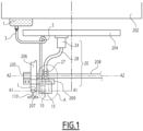
- Figure 1 schematically illustrates, seen in a front view, a lubricant apparatus, indicated by the overall reference number 100, for lubricating rails of a railway line.
- the various components of the lubricant apparatus 100 are mounted, as it will be described in further details hereinafter, on board on a railway vehicle, for example a wagon of train, schematically represented in figure 1 by the overall reference number 200.
- the railway vehicle 200 comprises:
- Couple of wheels such as the wheel 206, are mounted at the opposite sides of an associated mounting axle 208 which extends along an axis A2 transversal with respect to the longitudinal extension of the rails 110.
- the lubricant apparatus comprises at least:
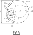
- the nozzle 10 comprises one more opening(s), e.g. slots, indicated in figure 3 by the reference number 11, which are arranged to dispense outwardly the lubricant onto a desired portion of the rail 110.
- opening(s) e.g. slots, indicated in figure 3 by the reference number 11, which are arranged to dispense outwardly the lubricant onto a desired portion of the rail 110.
- the nozzle 10 with its opening(s) 11 are arranged so that the flow of lubricant is spread selectively onto the portion of the rail 110, indicated in figure 1 by the letter L, constituting the contact interface with the flange 207 of an associated wheel 206 bearing over it when the railway vehicle 200 is travelling.
- the apparatus 100 further comprises an air blowing system, indicated in figure 1 by the overall reference number 20, which includes at least air blowing means.
- the air blowing means are positioned relative to nozzle 10 so that to blow air towards the nozzle 10 and cause the lubricant to be ejected out from the one or more openings 11 onto the desired portion L of the rail 110.
- the blowing means comprise an impeller 22; in the exemplary embodiment illustrated, the impeller 22 is schematically represented in figure 2 positioned inside a circular envelope 23 having a dimeter D2.
- the impeller 22 and the nozzle 10 are mounted spaced apart and substantially aligned to each other along a mounting axis A1 transversal with respect to the longitudinal extension of the rails 110.
- the mounting axis A1 is substantially parallel to the axis A2 of the wheel axle 208.
- the nozzle 10 and the impeller 22 are mounted offset ahead or aback the wheels of the railway vehicle 200.
- the nozzle 10 and the impeller 22 are mounted on the railway vehicle 200 ahead of the associated wheel 206 when the railway vehicle is travelling in one direction; clearly, if the railway vehicle 200 is proceeding in the opposite direction, then with respect to such opposite direction, the nozzle 10 and the impeller 22 result mounted aback or behind the wheel 206.
- the body of the wheel 206 is not interposed between the rail 110 and the nozzle 10.
- a mounting bracket 209 which is fixed at one end to the axle box 205, and is suitably shaped to extend from the box 205 around the front -or alternatively the back- part of the wheel 206.
- the mounting bracket 209 extends for example along a longitudinal direction parallel to the axis A1 and supports a cover 15 connected therewith.
- the cover e.g. of a substantially circular form and having for instance a diameter D1 as indicated in figures 2 and 3 , covers at least partially the nozzle 10 and the impeller 22, and is open at least on the side facing the rail 110.
- the air blowing system 20 of the lubricant apparatus 100 further comprises:
- the motor 24 can be for example any suitable motor available on the market, having for instance a speed up to 10000 rpm.
- the flexible shaft can be also any suitable type of shaft available on the market, e.g. a thin flexible shaft made of steel.
- Suitable bearings schematically represented in figure 2 by the reference number 29, allow the spindle 26 to rotate relative to the cover 15, around the axis C1.
- the lubricant apparatus 100 further comprises a conduit 3, e.g. a flexible hose or pipe having an inner diameter D4, which connects the tank 1 with the nozzle 10, and valve means 12 that are operatively connected to the nozzle 10.
- a conduit 3 e.g. a flexible hose or pipe having an inner diameter D4
- valve means 12 that are operatively connected to the nozzle 10.
- the valve means 22 are movable between a first position where they impede the flow of lubricant from the conduit 3 into the nozzle 10, and a second position where they means allow the lubricant to flow from the conduit 3 into the nozzle 10.
- the lubricant apparatus 100 further comprises a pump 5, preferably a positive displacement pump, which is arranged to push, once operated, lubricant to flow along the conduit 3 towards and up into the nozzle 10.
- a pump 5 preferably a positive displacement pump, which is arranged to push, once operated, lubricant to flow along the conduit 3 towards and up into the nozzle 10.
- valve means 12 comprises a piston 14, positioned at an end of the conduit 3 which is connected to the nozzle 10, and a spring 16, e.g. a soft spring, which is operatively connected to and interacts with the piston 14.
- a spring 16 e.g. a soft spring
- the piston 22 is mounted to move for a distance (d) along the axis C2; in particular, when the pump 5 is not active, the piston 14 is arranged to remain in said first position under the action of the spring 16, whereas under the action of the lubricant pushed by the pump 5, it moves downwardly in the second position, thus allowing flows of lubricant to enter into the nozzle 10.
- the pump 5 and the motor 24 are operated substantially synchronously to each other, and when the pump is actuated to push the lubricant and cause it to enter into the nozzle 10, also the motor 24 is actuated to properly start rotating the impeller 22.
- the functioning of the pump 5 and the motor 24 can be started for instance by a control unit (not illustrated in the figures) installed on board of the railway vehicle 200, which can be suitably programmed to start lubricating operations at desired interval of times during the travel, and/or to be actuated also by an operator.
- a control unit not illustrated in the figures
- the one or more openings 11 are properly configured to define, as a whole, an ejecting area, indicated in figure 3 for the sake of illustration by the capital letter E, from where the lubricating is selectively directed towards and onto the desired portion L of the rail 110.
- a plurality of apparatuses 100 can be installed on board of the same vehicle, or on board of different vehicles of a convoy or train.
- the apparatus 100 and related railway vehicle 200 according to the present invention allow achieving the intended aim since the lubrication of rails is carried out more efficiently and requires requiring a substantial less amount of lubricant with respect to known solutions, thus reducing consumption and waste of lubricants.
- the apparatus 100 and railway vehicle 200 thus conceived are susceptible of modifications and variations, all of which are within the scope of the inventive concept as defined in particular by the appended claims; for example, in relation to the specific application, some of the components can be differently configured or differently positioned.
- the motor 24 has been illustrated mounted beneath the frame 204 of a bogie, while the tank 1 has been illustrated fixed under the car body 202, but clearly and easily they could be positioned differently if desired or needed.
- the cover 15 and/or the envelope 23 can be differently shaped and/or can be realized in a single piece. The position, size, shape and number of each opening 11 can be properly selected according to the specific applications and/or specific needs.
Abstract
- a tank (1) containing a lubricant;
- a nozzle (10) adapted to receive lubricant form said tank (1), said nozzle (10) comprising one more openings (11) which are arranged to dispense outwardly the lubricant onto a desired portion (L) of said at least one rail (110);
- an air blowing system (20) comprising at least blowing means which are positioned relative to nozzle (10) to blow air towards the nozzle (10) and cause the lubricant to be ejected out from said one or more openings (11) onto said desired portion (L) of said at least one rail (110). The present invention provides also a railway vehicle comprising such lubricant apparatus (100).
Description
- The present invention relates to a lubricant apparatus for lubricating rails of a railway line, and to a railway vehicle comprising such lubricant apparatus.
- The lubricant apparatus according to the invention will be described hereinafter by making reference to its use on a car of a train without intending in any way to limit its possible application to railways vehicles composed by any number or cars or wagons, as well as to other types of railway vehicles, such as for example to metro convoys and to any possible railway application in general.
- As known, in the field of railway transportation, the lubrication of rails plays an important role as regard to the functional interaction with wheels of transiting railway vehicles, and heavily influences the duration of the rails themselves and of the wheels as well.
- Currently, one type of solutions foresees the use of lubricating systems that are installed on the ground at determined positions along the extension of the rails.
- Another type of solutions, to which the lubricant apparatus according to the present invention belongs to, foresees the use of lubricating systems which are mounted on board of trains, for instance below the car bodies of vehicles.
- In this case, a typical system currently adopted uses nozzles that eject lubricants on the flange of the wheels at required intervals while the train is travelling; in this way, the lubricant ejected moves along the circumference of the rotating wheel and lubricates also the associated rail.
- Although this solution allows achieving a fair degree of rail lubrication, it is not very efficient since the centrifugal forces involved cause the splashing of predominant quantities of lubricant on the underframe of the car body.
- Thus, there is an excessive consumption of lubricant, and the undesired and excessive splashing of the lubricant implies frequent cleaning interventions.
- Further, other concerns and constraints of known lubricating systems reside in their costs and overall dimensions, and in particular their overall weight, which should be as reduced as possible.
- The present invention is aimed at providing a solution for efficiently lubricating rails of railway lines which can mitigate at least partially, at least some of the above indicated issues.
- To this end, the present invention provides a lubricant apparatus for lubricating at least one rail of a railway line, characterized in that it comprises, suitable to be mounted on board on a railway vehicle, at least:
- a tank containing a lubricant;
- a nozzle adapted to receive lubricant form said tank, said nozzle comprising one more openings which are arranged to dispense outwardly the lubricant onto a desired portion of said at least one rail;
- an air blowing system comprising at least blowing means which are positioned relative to nozzle to blow air towards the nozzle and cause the lubricant to be ejected out from said one or more openings onto said desired portion of said at least one rail.
- According to the present invention, there is also provided a railway vehicle characterized in that it comprises a lubricant apparatus as above indicated, and in particular as described hereinafter and defined in the appended relevant claims.
- Further characteristics and advantages will become apparent from the description of some preferred but not exclusive exemplary embodiments of a lubricant apparatus and related railway vehicle according to the present disclosure, illustrated only by way of non-limitative examples with the accompanying drawings, wherein:
-
Figure 1 is a front view schematically showing a possible embodiment of a lubricant apparatus according to the invention. -
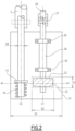
Figure 2 is a schematic view illustrating in more details the encircled area A offigure 1 ; -
Figure 3 is a schematic top view of some components offigure 2 . - It should be noted that in the detailed description that follows, identical or similar components, either from a structural and/or functional point of view, have the same reference numerals, regardless of whether they are shown in different embodiments of the present disclosure; it should also be noted that in order to clearly and concisely describe the present disclosure, the drawings may not necessarily be to scale and certain features of the disclosure may be shown in somewhat schematic form.
- Further, when the term "adapted" or "arranged" or "configured" or "shaped" or "set" is used herein while referring to any component as a whole, or to any part of a component, or to a combination of components, it has to be understood that it means and encompasses correspondingly either the structure, and/or configuration and/or form and/or positioning of the related component or part thereof, or combinations, such term refers to.
- In addition, when the term "about" or "substantial" or "substantially" is used herein, it has to be understood as encompassing an actual variation of plus or
minus 5% with respect to an indicated reference value, axis, time or position, and when the terms transversal or transversally are hereby used, they have to be understood as encompassing a direction non-parallel to the reference part(s) or direction(s)/axis they refer to, and perpendicularity has to be considered a specific case of transverse direction. -
Figure 1 schematically illustrates, seen in a front view, a lubricant apparatus, indicated by the overall reference number 100, for lubricating rails of a railway line. - For ease of illustration, in
figure 1 there is depicted only one rail indicated by thereference number 110. - According to the invention, the various components of the lubricant apparatus 100 are mounted, as it will be described in further details hereinafter, on board on a railway vehicle, for example a wagon of train, schematically represented in
figure 1 by the overall reference number 200. - According to solutions well known in the art and therefore not described hereinafter in details, the railway vehicle 200 comprises:
- a car body, schematically represented in
figure 1 by thereference number 202; - a plurality of bogies, a frame of one of which is schematically represented in
figure 1 with thereference number 204; - a plurality of wheels, only one of which is represented in
figure 1 by thereference number 206. - Couple of wheels, such as the
wheel 206, are mounted at the opposite sides of an associatedmounting axle 208 which extends along an axis A2 transversal with respect to the longitudinal extension of therails 110. - The lubricant apparatus according to the invention comprises at least:
- a tank 1 containing a lubricant, which is for example mounted beneath the
car body 202 as illustrated in the exemplary embodiment offigure 1 ; - a
nozzle 10 which is adapted to receive lubricant from the tank 1. - In particular, the
nozzle 10 comprises one more opening(s), e.g. slots, indicated infigure 3 by thereference number 11, which are arranged to dispense outwardly the lubricant onto a desired portion of therail 110. - In particular, as per details described hereinafter, the
nozzle 10 with its opening(s) 11 are arranged so that the flow of lubricant is spread selectively onto the portion of therail 110, indicated infigure 1 by the letter L, constituting the contact interface with theflange 207 of an associatedwheel 206 bearing over it when the railway vehicle 200 is travelling. - Usefully, the apparatus 100 according to the invention further comprises an air blowing system, indicated in
figure 1 by theoverall reference number 20, which includes at least air blowing means. - In particular, the air blowing means are positioned relative to
nozzle 10 so that to blow air towards thenozzle 10 and cause the lubricant to be ejected out from the one ormore openings 11 onto the desired portion L of therail 110. - According to one possible embodiment, the blowing means comprise an
impeller 22; in the exemplary embodiment illustrated, theimpeller 22 is schematically represented infigure 2 positioned inside acircular envelope 23 having a dimeter D2. - Conveniently, according to a possible embodiment, the
impeller 22 and thenozzle 10 are mounted spaced apart and substantially aligned to each other along a mounting axis A1 transversal with respect to the longitudinal extension of therails 110. - In particular, the mounting axis A1 is substantially parallel to the axis A2 of the
wheel axle 208. - Usefully, in the lubricant apparatus 100 according to the invention, with respect to a travelling direction X of the railway vehicle 200 along a railway line, the
nozzle 10 and theimpeller 22 are mounted offset ahead or aback the wheels of the railway vehicle 200. - Hence, with reference to the exemplary embodiment illustrated in
figure 1 , thenozzle 10 and theimpeller 22 are mounted on the railway vehicle 200 ahead of the associatedwheel 206 when the railway vehicle is travelling in one direction; clearly, if the railway vehicle 200 is proceeding in the opposite direction, then with respect to such opposite direction, thenozzle 10 and theimpeller 22 result mounted aback or behind thewheel 206. - In this way, with reference to a lateral view along a side of the railway vehicle 200, the body of the
wheel 206 is not interposed between therail 110 and thenozzle 10. - In particular, according to an exemplary embodiment illustrated in
figure 1 , in the lubricant apparatus 100 there is provided amounting bracket 209 which is fixed at one end to theaxle box 205, and is suitably shaped to extend from thebox 205 around the front -or alternatively the back- part of thewheel 206. - The
mounting bracket 209 extends for example along a longitudinal direction parallel to the axis A1 and supports acover 15 connected therewith. The cover, e.g. of a substantially circular form and having for instance a diameter D1 as indicated infigures 2 and3 , covers at least partially thenozzle 10 and theimpeller 22, and is open at least on the side facing therail 110. - In a possible embodiment, as illustrated in
figures 1 and2 , the air blowingsystem 20 of the lubricant apparatus 100 according to the invention, further comprises: - a
motor 24, preferably a high-speed motor, suitable to provide the energy required to actuate theimpeller 22; - a
spindle 26 connected to and driving theimpeller 22; and - a
flexible shaft 28 on one side connected to and driven by themotor 24 and on the opposite side connected to thespindle 26 via aflexible coupling 27. - The
motor 24 can be for example any suitable motor available on the market, having for instance a speed up to 10000 rpm. - In turn, the flexible shaft can be also any suitable type of shaft available on the market, e.g. a thin flexible shaft made of steel.
- Suitable bearings, schematically represented in
figure 2 by thereference number 29, allow thespindle 26 to rotate relative to thecover 15, around the axis C1. - As illustrated in
figures 1 and2 , the lubricant apparatus 100 further comprises aconduit 3, e.g. a flexible hose or pipe having an inner diameter D4, which connects the tank 1 with thenozzle 10, and valve means 12 that are operatively connected to thenozzle 10. - The valve means 22 are movable between a first position where they impede the flow of lubricant from the
conduit 3 into thenozzle 10, and a second position where they means allow the lubricant to flow from theconduit 3 into thenozzle 10. - According to a possible embodiment, the lubricant apparatus 100 further comprises a
pump 5, preferably a positive displacement pump, which is arranged to push, once operated, lubricant to flow along theconduit 3 towards and up into thenozzle 10. - In particular, as schematically illustrated in
figure 2 , the valve means 12 comprises apiston 14, positioned at an end of theconduit 3 which is connected to thenozzle 10, and aspring 16, e.g. a soft spring, which is operatively connected to and interacts with thepiston 14. - For instance, as schematically represented in
figure 2 , thepiston 22 is mounted to move for a distance (d) along the axis C2; in particular, when thepump 5 is not active, thepiston 14 is arranged to remain in said first position under the action of thespring 16, whereas under the action of the lubricant pushed by thepump 5, it moves downwardly in the second position, thus allowing flows of lubricant to enter into thenozzle 10. - Usefully, in the lubricant apparatus 100 according to the invention, the
pump 5 and themotor 24 are operated substantially synchronously to each other, and when the pump is actuated to push the lubricant and cause it to enter into thenozzle 10, also themotor 24 is actuated to properly start rotating theimpeller 22. - The functioning of the
pump 5 and themotor 24 can be started for instance by a control unit (not illustrated in the figures) installed on board of the railway vehicle 200, which can be suitably programmed to start lubricating operations at desired interval of times during the travel, and/or to be actuated also by an operator. - In practice, when the pump 5 (and the
motor 24 synchronously therewith) is triggered, the lubricant is pushed toward thenozzle 10 and overcomes the contrasting force of thespring 16, thus displacing thepiston 14 and being allowed to enter into thenozzle 10. The lubricant spills out and spreads over a certain area, indicated infigure 3 by an approximatively circular line D3, just for the sake of exemplary illustration. The rotation of theimpeller 22, caused by themotor 24, generates a centrifugal force that causes the lubricant to be ejected out from the one ormore openings 11, e.g. the two slots illustrated infigure 2 . - The one or
more openings 11 are properly configured to define, as a whole, an ejecting area, indicated infigure 3 for the sake of illustration by the capital letter E, from where the lubricating is selectively directed towards and onto the desired portion L of therail 110. - Clearly, what above described for one
rail 110, can be applied also to the other rail of the railway line. - To this end, and depending on the applications and/or specific needed, it is possible to simply mirror on the other side of the railway vehicle the lubricant apparatus above described, thus utilizing two substantially identical apparatuses 100.
- Alternatively, in order to lubricate the two rails of a railway line, it is possible to have some common components and duplicate only some others, as the person skilled in the art would readily appreciate. For example, it is possible to use a common tank dispensing lubricant for both rails.
- Further, a plurality of apparatuses 100 can be installed on board of the same vehicle, or on board of different vehicles of a convoy or train.
- Hence, it is evident from the foregoing description that the apparatus 100 and related railway vehicle 200 according to the present invention allow achieving the intended aim since the lubrication of rails is carried out more efficiently and requires requiring a substantial less amount of lubricant with respect to known solutions, thus reducing consumption and waste of lubricants.
- These results are achieved according to an apparatus that, as a whole, is sufficiently light and relatively easy to be realized and installed at competitive costs.
- The apparatus 100 and railway vehicle 200 thus conceived are susceptible of modifications and variations, all of which are within the scope of the inventive concept as defined in particular by the appended claims; for example, in relation to the specific application, some of the components can be differently configured or differently positioned. For instance, in the exemplary embodiment illustrated in
figure 2 , themotor 24 has been illustrated mounted beneath theframe 204 of a bogie, while the tank 1 has been illustrated fixed under thecar body 202, but clearly and easily they could be positioned differently if desired or needed. Thecover 15 and/or theenvelope 23 can be differently shaped and/or can be realized in a single piece. The position, size, shape and number of eachopening 11 can be properly selected according to the specific applications and/or specific needs. - All the details may furthermore be replaced with technically equivalent elements.
Claims (10)
- A lubricant apparatus (100) for lubricating at least one rail (110) of a railway line, characterized in that it comprises, suitable to be mounted on board on a railway vehicle (200), at least:- a tank (1) containing a lubricant;- a nozzle (10) adapted to receive lubricant form said tank (1), said nozzle (10) comprising one more openings (11) which are arranged to dispense outwardly the lubricant onto a desired portion (L) of said at least one rail (110);- an air blowing system (20) comprising at least blowing means which are positioned relative to nozzle (10) to blow air towards the nozzle (10) and cause the lubricant to be ejected out from said one or more openings (11) onto said desired portion (L) of said at least one rail (110).
- The lubricant apparatus (100) according to claim 1, wherein said blowing means comprise or are constituted by an impeller (22).
- The lubricant apparatus (100) according to claim 2, wherein said impeller (22) and said nozzle (10) are mounted spaced apart and substantially aligned to each other along a mounting axis (A1) transversal with respect to the longitudinal extension of the at least one rail (110).
- The lubricant apparatus (100) according to claim 3, wherein said mounting axis (A1) is substantially parallel to a longitudinal axis (A2) or a wheel axle (208) of the railway vehicle (200).
- The lubricant apparatus (100) according to any one of claims 2 to 4, wherein, with respect to a travelling direction (X) of the railway vehicle (200) along said railway line, said nozzle (10) and said impeller (22) are mounted offset ahead or aback of a wheel (206) of the railway vehicle (200).
- The lubricant apparatus (100) according to any one of claims 2 to 5, wherein said air blowing system (20) further comprises:- a motor (24) providing energy suitable for driving said impeller (22);- a spindle (26) connected to and driving said impeller (22); and- a flexible shaft (28) on one side connected to and driven by said motor (24) and on the opposite side connected to the spindle (26) via a flexible coupling (27).
- The lubricant apparatus (100) according to any one of claims 1 to 6, further comprising a conduit (3) connecting said tank (1) with said nozzle (10), valve means (12) operatively connected to said nozzle (10) and movable between a first position where said valve means (12) impede the flow of lubricant from said conduit (3) into said nozzle (10) and a second position where said valve means (12) allow the lubricant to flow from said conduit (3) into said nozzle (10), and a pump (5) which is arranged to push, once operated, lubricant to flow from said conduit (3) towards said nozzle (10).
- The lubricant apparatus (100) according to claim 7, wherein said valve means (12) comprises a piston (14), positioned at an end of the conduit (3) connected to said nozzle (10), and a spring (16) operatively connected to said piston (14).
- The lubricant apparatus (100) according to claim 7 or 8 when each of them depends from claim 6, wherein said pump (5) and said motor (24) are operated substantially synchronously to each other.
- A railway vehicle (200) comprising at least one apparatus according to any one of claims 1 to 9.
Applications Claiming Priority (1)
| Application Number | Priority Date | Filing Date | Title |
|---|---|---|---|
| IN202241022090 | 2022-04-13 |
Publications (1)
| Publication Number | Publication Date |
|---|---|
| EP4261102A1 true EP4261102A1 (en) | 2023-10-18 |
Family
ID=86006518
Family Applications (1)
| Application Number | Title | Priority Date | Filing Date |
|---|---|---|---|
| EP23167489.6A Pending EP4261102A1 (en) | 2022-04-13 | 2023-04-12 | Lubricant apparatus for lubricating rails of a railway line, and railway vehicle comprising such lubricant apparatus |
Country Status (1)
| Country | Link |
|---|---|
| EP (1) | EP4261102A1 (en) |
Citations (3)
| Publication number | Priority date | Publication date | Assignee | Title |
|---|---|---|---|---|
| FR988232A (en) * | 1949-06-13 | 1951-08-24 | Sncf | Mechanically operated rail lubrication system |
| EP0703135A1 (en) * | 1994-09-24 | 1996-03-27 | De Limon Fluhme Gmbh | Spray nozzle for the wheel profile lubrification of a rail vehicle |
| WO2002087806A2 (en) * | 2001-04-27 | 2002-11-07 | Lubriquip, Inc. | Rail lubrication system |
-
2023
- 2023-04-12 EP EP23167489.6A patent/EP4261102A1/en active Pending
Patent Citations (3)
| Publication number | Priority date | Publication date | Assignee | Title |
|---|---|---|---|---|
| FR988232A (en) * | 1949-06-13 | 1951-08-24 | Sncf | Mechanically operated rail lubrication system |
| EP0703135A1 (en) * | 1994-09-24 | 1996-03-27 | De Limon Fluhme Gmbh | Spray nozzle for the wheel profile lubrification of a rail vehicle |
| WO2002087806A2 (en) * | 2001-04-27 | 2002-11-07 | Lubriquip, Inc. | Rail lubrication system |
Similar Documents
| Publication | Publication Date | Title |
|---|---|---|
| CA2235640C (en) | On board lubrication systems for lubricating top of rail for cars and rail gage side/wheel flange for locomotives | |
| US5477941A (en) | On-board lubrication system for direct application to curved and tangent railroad track | |
| US7290807B2 (en) | Method and system of limiting the application of sand to a railroad rail | |
| US6893058B2 (en) | Railway train friction management and control system and method | |
| US7121383B2 (en) | Wayside rail lubrication apparatus and method | |
| EP1226059B1 (en) | Wayside wheel lubricator | |
| US10358783B2 (en) | Rail conditioning system | |
| US6182793B1 (en) | Lubricant delivery system for lubricating rail wheel flanges | |
| EP0288589A1 (en) | Light tramway drive unit with driving or trailing steering trucks having a single wheel, and with a low floor passing troughout the car for single-step boarding | |
| WO2017070677A1 (en) | Systems and method for a traction system | |
| EP4261102A1 (en) | Lubricant apparatus for lubricating rails of a railway line, and railway vehicle comprising such lubricant apparatus | |
| US6186411B1 (en) | Wheel flange lubrication nozzle | |
| RU2348557C1 (en) | Lubricating device and modifier of friction on rails | |
| JP4680089B2 (en) | Friction adjusting device and friction adjusting method | |
| US2184969A (en) | Rail wetting device for railroads | |
| JP2012184829A (en) | Oil applicator for wheel of locomotive within premises | |
| CN105416339A (en) | Electric curve steel rail lubricating agent coating vehicle | |
| JP2011063175A (en) | Method of cleaning rail head top surface and wheel tread surface by compressed air, and device thereof | |
| DE2353912A1 (en) | Wheel flange lubrication system for rail vehicles - incorporates centrifugal and mechanical switch to actuate a solenoid valve | |
| RU83987U1 (en) | DEVICE FOR LUBRICATION ON RAILS | |
| SU1158415A1 (en) | Device for cleaning railway car wheel rim faces | |
| SU969805A1 (en) | Rail crossing | |
| CN105438216A (en) | Vehicle-mounted curve rail lubricating agent lateral spraying device | |
| US1167514A (en) | Pneumatic flange-oiler for car-wheels. | |
| EP3280627B1 (en) | Rail vehicle having a treatment device for rail drying |
Legal Events
| Date | Code | Title | Description |
|---|---|---|---|
| PUAI | Public reference made under article 153(3) epc to a published international application that has entered the european phase |
Free format text: ORIGINAL CODE: 0009012 |
|
| STAA | Information on the status of an ep patent application or granted ep patent |
Free format text: STATUS: THE APPLICATION HAS BEEN PUBLISHED |
|
| STAA | Information on the status of an ep patent application or granted ep patent |
Free format text: STATUS: REQUEST FOR EXAMINATION WAS MADE |
|
| AK | Designated contracting states |
Kind code of ref document: A1 Designated state(s): AL AT BE BG CH CY CZ DE DK EE ES FI FR GB GR HR HU IE IS IT LI LT LU LV MC ME MK MT NL NO PL PT RO RS SE SI SK SM TR |
|
| 17P | Request for examination filed |
Effective date: 20230928 |
|
| RBV | Designated contracting states (corrected) |
Designated state(s): AL AT BE BG CH CY CZ DE DK EE ES FI FR GB GR HR HU IE IS IT LI LT LU LV MC ME MK MT NL NO PL PT RO RS SE SI SK SM TR |