EP4260899A1 - Skin care assembly - Google Patents
Skin care assembly Download PDFInfo
- Publication number
- EP4260899A1 EP4260899A1 EP22871709.6A EP22871709A EP4260899A1 EP 4260899 A1 EP4260899 A1 EP 4260899A1 EP 22871709 A EP22871709 A EP 22871709A EP 4260899 A1 EP4260899 A1 EP 4260899A1
- Authority
- EP
- European Patent Office
- Prior art keywords
- skin care
- cover
- component
- care assembly
- cold compress
- Prior art date
- Legal status (The legal status is an assumption and is not a legal conclusion. Google has not performed a legal analysis and makes no representation as to the accuracy of the status listed.)
- Pending
Links
- 238000005057 refrigeration Methods 0.000 claims abstract description 126
- 238000001126 phototherapy Methods 0.000 claims description 46
- 238000007789 sealing Methods 0.000 claims description 19
- 239000000463 material Substances 0.000 claims description 12
- WABPQHHGFIMREM-UHFFFAOYSA-N lead(0) Chemical compound [Pb] WABPQHHGFIMREM-UHFFFAOYSA-N 0.000 claims description 6
- 230000009471 action Effects 0.000 claims description 5
- 239000007788 liquid Substances 0.000 claims description 5
- 229910052594 sapphire Inorganic materials 0.000 claims description 5
- 239000010980 sapphire Substances 0.000 claims description 5
- 239000002344 surface layer Substances 0.000 claims description 5
- 229910052782 aluminium Inorganic materials 0.000 claims description 2
- XAGFODPZIPBFFR-UHFFFAOYSA-N aluminium Chemical compound [Al] XAGFODPZIPBFFR-UHFFFAOYSA-N 0.000 claims description 2
- 230000005611 electricity Effects 0.000 claims description 2
- 230000005389 magnetism Effects 0.000 claims description 2
- 238000000465 moulding Methods 0.000 claims description 2
- 230000003796 beauty Effects 0.000 abstract description 24
- 230000000694 effects Effects 0.000 abstract description 21
- 239000002537 cosmetic Substances 0.000 abstract description 10
- 210000003491 skin Anatomy 0.000 description 197
- 239000010410 layer Substances 0.000 description 23
- 238000000034 method Methods 0.000 description 13
- 230000008569 process Effects 0.000 description 11
- 230000001965 increasing effect Effects 0.000 description 8
- 210000002615 epidermis Anatomy 0.000 description 7
- VYPSYNLAJGMNEJ-UHFFFAOYSA-N Silicium dioxide Chemical compound O=[Si]=O VYPSYNLAJGMNEJ-UHFFFAOYSA-N 0.000 description 4
- 210000004207 dermis Anatomy 0.000 description 3
- 239000000741 silica gel Substances 0.000 description 3
- 229910002027 silica gel Inorganic materials 0.000 description 3
- 238000012546 transfer Methods 0.000 description 3
- XLYOFNOQVPJJNP-UHFFFAOYSA-N water Substances O XLYOFNOQVPJJNP-UHFFFAOYSA-N 0.000 description 3
- 238000010586 diagram Methods 0.000 description 2
- 230000002500 effect on skin Effects 0.000 description 2
- 230000001815 facial effect Effects 0.000 description 2
- 239000004519 grease Substances 0.000 description 2
- 230000017525 heat dissipation Effects 0.000 description 2
- 229920001296 polysiloxane Polymers 0.000 description 2
- 239000011148 porous material Substances 0.000 description 2
- 238000012545 processing Methods 0.000 description 2
- 230000035939 shock Effects 0.000 description 2
- 230000004936 stimulating effect Effects 0.000 description 2
- WKBPZYKAUNRMKP-UHFFFAOYSA-N 1-[2-(2,4-dichlorophenyl)pentyl]1,2,4-triazole Chemical compound C=1C=C(Cl)C=C(Cl)C=1C(CCC)CN1C=NC=N1 WKBPZYKAUNRMKP-UHFFFAOYSA-N 0.000 description 1
- 102000008186 Collagen Human genes 0.000 description 1
- 108010035532 Collagen Proteins 0.000 description 1
- 239000011324 bead Substances 0.000 description 1
- 239000000919 ceramic Substances 0.000 description 1
- 229920001436 collagen Polymers 0.000 description 1
- 230000008602 contraction Effects 0.000 description 1
- PMHQVHHXPFUNSP-UHFFFAOYSA-M copper(1+);methylsulfanylmethane;bromide Chemical compound Br[Cu].CSC PMHQVHHXPFUNSP-UHFFFAOYSA-M 0.000 description 1
- 230000008878 coupling Effects 0.000 description 1
- 238000010168 coupling process Methods 0.000 description 1
- 238000005859 coupling reaction Methods 0.000 description 1
- 239000013078 crystal Substances 0.000 description 1
- 238000013461 design Methods 0.000 description 1
- 238000011161 development Methods 0.000 description 1
- 230000005489 elastic deformation Effects 0.000 description 1
- 239000013013 elastic material Substances 0.000 description 1
- 238000005516 engineering process Methods 0.000 description 1
- 230000002708 enhancing effect Effects 0.000 description 1
- 239000011521 glass Substances 0.000 description 1
- 239000003292 glue Substances 0.000 description 1
- 238000010438 heat treatment Methods 0.000 description 1
- 229910010272 inorganic material Inorganic materials 0.000 description 1
- 239000011147 inorganic material Substances 0.000 description 1
- 230000002452 interceptive effect Effects 0.000 description 1
- 239000004816 latex Substances 0.000 description 1
- 229920000126 latex Polymers 0.000 description 1
- 238000012423 maintenance Methods 0.000 description 1
- 229910052751 metal Inorganic materials 0.000 description 1
- 239000002184 metal Substances 0.000 description 1
- 210000003205 muscle Anatomy 0.000 description 1
- 230000003287 optical effect Effects 0.000 description 1
- 239000011368 organic material Substances 0.000 description 1
- 239000004033 plastic Substances 0.000 description 1
- 229920003023 plastic Polymers 0.000 description 1
- 239000011034 rock crystal Substances 0.000 description 1
- 239000005368 silicate glass Substances 0.000 description 1
- 210000004927 skin cell Anatomy 0.000 description 1
- 230000000638 stimulation Effects 0.000 description 1
- 238000002560 therapeutic procedure Methods 0.000 description 1
- 210000001519 tissue Anatomy 0.000 description 1
- 239000011031 topaz Substances 0.000 description 1
- 229910052853 topaz Inorganic materials 0.000 description 1
- 230000009466 transformation Effects 0.000 description 1
Images


Classifications
-
- A—HUMAN NECESSITIES
- A61—MEDICAL OR VETERINARY SCIENCE; HYGIENE
- A61N—ELECTROTHERAPY; MAGNETOTHERAPY; RADIATION THERAPY; ULTRASOUND THERAPY
- A61N1/00—Electrotherapy; Circuits therefor
- A61N1/18—Applying electric currents by contact electrodes
- A61N1/32—Applying electric currents by contact electrodes alternating or intermittent currents
- A61N1/328—Applying electric currents by contact electrodes alternating or intermittent currents for improving the appearance of the skin, e.g. facial toning or wrinkle treatment
-
- A—HUMAN NECESSITIES
- A61—MEDICAL OR VETERINARY SCIENCE; HYGIENE
- A61F—FILTERS IMPLANTABLE INTO BLOOD VESSELS; PROSTHESES; DEVICES PROVIDING PATENCY TO, OR PREVENTING COLLAPSING OF, TUBULAR STRUCTURES OF THE BODY, e.g. STENTS; ORTHOPAEDIC, NURSING OR CONTRACEPTIVE DEVICES; FOMENTATION; TREATMENT OR PROTECTION OF EYES OR EARS; BANDAGES, DRESSINGS OR ABSORBENT PADS; FIRST-AID KITS
- A61F7/00—Heating or cooling appliances for medical or therapeutic treatment of the human body
- A61F7/007—Heating or cooling appliances for medical or therapeutic treatment of the human body characterised by electric heating
-
- A—HUMAN NECESSITIES
- A61—MEDICAL OR VETERINARY SCIENCE; HYGIENE
- A61N—ELECTROTHERAPY; MAGNETOTHERAPY; RADIATION THERAPY; ULTRASOUND THERAPY
- A61N1/00—Electrotherapy; Circuits therefor
- A61N1/02—Details
- A61N1/04—Electrodes
- A61N1/0404—Electrodes for external use
-
- A—HUMAN NECESSITIES
- A61—MEDICAL OR VETERINARY SCIENCE; HYGIENE
- A61B—DIAGNOSIS; SURGERY; IDENTIFICATION
- A61B18/00—Surgical instruments, devices or methods for transferring non-mechanical forms of energy to or from the body
- A61B18/18—Surgical instruments, devices or methods for transferring non-mechanical forms of energy to or from the body by applying electromagnetic radiation, e.g. microwaves
- A61B18/20—Surgical instruments, devices or methods for transferring non-mechanical forms of energy to or from the body by applying electromagnetic radiation, e.g. microwaves using laser
- A61B18/203—Surgical instruments, devices or methods for transferring non-mechanical forms of energy to or from the body by applying electromagnetic radiation, e.g. microwaves using laser applying laser energy to the outside of the body
-
- A—HUMAN NECESSITIES
- A61—MEDICAL OR VETERINARY SCIENCE; HYGIENE
- A61N—ELECTROTHERAPY; MAGNETOTHERAPY; RADIATION THERAPY; ULTRASOUND THERAPY
- A61N1/00—Electrotherapy; Circuits therefor
- A61N1/02—Details
- A61N1/04—Electrodes
- A61N1/0404—Electrodes for external use
- A61N1/0408—Use-related aspects
- A61N1/0452—Specially adapted for transcutaneous muscle stimulation [TMS]
-
- A—HUMAN NECESSITIES
- A61—MEDICAL OR VETERINARY SCIENCE; HYGIENE
- A61N—ELECTROTHERAPY; MAGNETOTHERAPY; RADIATION THERAPY; ULTRASOUND THERAPY
- A61N1/00—Electrotherapy; Circuits therefor
- A61N1/02—Details
- A61N1/04—Electrodes
- A61N1/0404—Electrodes for external use
- A61N1/0472—Structure-related aspects
- A61N1/0476—Array electrodes (including any electrode arrangement with more than one electrode for at least one of the polarities)
-
- A—HUMAN NECESSITIES
- A61—MEDICAL OR VETERINARY SCIENCE; HYGIENE
- A61N—ELECTROTHERAPY; MAGNETOTHERAPY; RADIATION THERAPY; ULTRASOUND THERAPY
- A61N1/00—Electrotherapy; Circuits therefor
- A61N1/02—Details
- A61N1/04—Electrodes
- A61N1/06—Electrodes for high-frequency therapy
-
- A—HUMAN NECESSITIES
- A61—MEDICAL OR VETERINARY SCIENCE; HYGIENE
- A61N—ELECTROTHERAPY; MAGNETOTHERAPY; RADIATION THERAPY; ULTRASOUND THERAPY
- A61N1/00—Electrotherapy; Circuits therefor
- A61N1/18—Applying electric currents by contact electrodes
-
- A—HUMAN NECESSITIES
- A61—MEDICAL OR VETERINARY SCIENCE; HYGIENE
- A61N—ELECTROTHERAPY; MAGNETOTHERAPY; RADIATION THERAPY; ULTRASOUND THERAPY
- A61N1/00—Electrotherapy; Circuits therefor
- A61N1/18—Applying electric currents by contact electrodes
- A61N1/32—Applying electric currents by contact electrodes alternating or intermittent currents
- A61N1/36—Applying electric currents by contact electrodes alternating or intermittent currents for stimulation
- A61N1/36014—External stimulators, e.g. with patch electrodes
-
- A—HUMAN NECESSITIES
- A61—MEDICAL OR VETERINARY SCIENCE; HYGIENE
- A61N—ELECTROTHERAPY; MAGNETOTHERAPY; RADIATION THERAPY; ULTRASOUND THERAPY
- A61N1/00—Electrotherapy; Circuits therefor
- A61N1/40—Applying electric fields by inductive or capacitive coupling ; Applying radio-frequency signals
-
- A—HUMAN NECESSITIES
- A61—MEDICAL OR VETERINARY SCIENCE; HYGIENE
- A61N—ELECTROTHERAPY; MAGNETOTHERAPY; RADIATION THERAPY; ULTRASOUND THERAPY
- A61N1/00—Electrotherapy; Circuits therefor
- A61N1/40—Applying electric fields by inductive or capacitive coupling ; Applying radio-frequency signals
- A61N1/403—Applying electric fields by inductive or capacitive coupling ; Applying radio-frequency signals for thermotherapy, e.g. hyperthermia
-
- A—HUMAN NECESSITIES
- A61—MEDICAL OR VETERINARY SCIENCE; HYGIENE
- A61N—ELECTROTHERAPY; MAGNETOTHERAPY; RADIATION THERAPY; ULTRASOUND THERAPY
- A61N5/00—Radiation therapy
- A61N5/06—Radiation therapy using light
- A61N5/0613—Apparatus adapted for a specific treatment
- A61N5/0616—Skin treatment other than tanning
- A61N5/0617—Hair treatment
-
- H—ELECTRICITY
- H05—ELECTRIC TECHNIQUES NOT OTHERWISE PROVIDED FOR
- H05K—PRINTED CIRCUITS; CASINGS OR CONSTRUCTIONAL DETAILS OF ELECTRIC APPARATUS; MANUFACTURE OF ASSEMBLAGES OF ELECTRICAL COMPONENTS
- H05K7/00—Constructional details common to different types of electric apparatus
- H05K7/20—Modifications to facilitate cooling, ventilating, or heating
- H05K7/2029—Modifications to facilitate cooling, ventilating, or heating using a liquid coolant with phase change in electronic enclosures
- H05K7/20336—Heat pipes, e.g. wicks or capillary pumps
-
- H—ELECTRICITY
- H05—ELECTRIC TECHNIQUES NOT OTHERWISE PROVIDED FOR
- H05K—PRINTED CIRCUITS; CASINGS OR CONSTRUCTIONAL DETAILS OF ELECTRIC APPARATUS; MANUFACTURE OF ASSEMBLAGES OF ELECTRICAL COMPONENTS
- H05K7/00—Constructional details common to different types of electric apparatus
- H05K7/20—Modifications to facilitate cooling, ventilating, or heating
- H05K7/2039—Modifications to facilitate cooling, ventilating, or heating characterised by the heat transfer by conduction from the heat generating element to a dissipating body
-
- A—HUMAN NECESSITIES
- A61—MEDICAL OR VETERINARY SCIENCE; HYGIENE
- A61B—DIAGNOSIS; SURGERY; IDENTIFICATION
- A61B18/00—Surgical instruments, devices or methods for transferring non-mechanical forms of energy to or from the body
- A61B2018/00005—Cooling or heating of the probe or tissue immediately surrounding the probe
- A61B2018/00047—Cooling or heating of the probe or tissue immediately surrounding the probe using Peltier effect
-
- A—HUMAN NECESSITIES
- A61—MEDICAL OR VETERINARY SCIENCE; HYGIENE
- A61B—DIAGNOSIS; SURGERY; IDENTIFICATION
- A61B18/00—Surgical instruments, devices or methods for transferring non-mechanical forms of energy to or from the body
- A61B2018/00315—Surgical instruments, devices or methods for transferring non-mechanical forms of energy to or from the body for treatment of particular body parts
- A61B2018/00452—Skin
- A61B2018/00476—Hair follicles
-
- A—HUMAN NECESSITIES
- A61—MEDICAL OR VETERINARY SCIENCE; HYGIENE
- A61F—FILTERS IMPLANTABLE INTO BLOOD VESSELS; PROSTHESES; DEVICES PROVIDING PATENCY TO, OR PREVENTING COLLAPSING OF, TUBULAR STRUCTURES OF THE BODY, e.g. STENTS; ORTHOPAEDIC, NURSING OR CONTRACEPTIVE DEVICES; FOMENTATION; TREATMENT OR PROTECTION OF EYES OR EARS; BANDAGES, DRESSINGS OR ABSORBENT PADS; FIRST-AID KITS
- A61F7/00—Heating or cooling appliances for medical or therapeutic treatment of the human body
- A61F2007/0001—Body part
- A61F2007/0002—Head or parts thereof
- A61F2007/0003—Face
-
- A—HUMAN NECESSITIES
- A61—MEDICAL OR VETERINARY SCIENCE; HYGIENE
- A61F—FILTERS IMPLANTABLE INTO BLOOD VESSELS; PROSTHESES; DEVICES PROVIDING PATENCY TO, OR PREVENTING COLLAPSING OF, TUBULAR STRUCTURES OF THE BODY, e.g. STENTS; ORTHOPAEDIC, NURSING OR CONTRACEPTIVE DEVICES; FOMENTATION; TREATMENT OR PROTECTION OF EYES OR EARS; BANDAGES, DRESSINGS OR ABSORBENT PADS; FIRST-AID KITS
- A61F7/00—Heating or cooling appliances for medical or therapeutic treatment of the human body
- A61F2007/0001—Body part
- A61F2007/0052—Body part for treatment of skin or hair
-
- A—HUMAN NECESSITIES
- A61—MEDICAL OR VETERINARY SCIENCE; HYGIENE
- A61F—FILTERS IMPLANTABLE INTO BLOOD VESSELS; PROSTHESES; DEVICES PROVIDING PATENCY TO, OR PREVENTING COLLAPSING OF, TUBULAR STRUCTURES OF THE BODY, e.g. STENTS; ORTHOPAEDIC, NURSING OR CONTRACEPTIVE DEVICES; FOMENTATION; TREATMENT OR PROTECTION OF EYES OR EARS; BANDAGES, DRESSINGS OR ABSORBENT PADS; FIRST-AID KITS
- A61F7/00—Heating or cooling appliances for medical or therapeutic treatment of the human body
- A61F7/007—Heating or cooling appliances for medical or therapeutic treatment of the human body characterised by electric heating
- A61F2007/0075—Heating or cooling appliances for medical or therapeutic treatment of the human body characterised by electric heating using a Peltier element, e.g. near the spot to be heated or cooled
-
- A—HUMAN NECESSITIES
- A61—MEDICAL OR VETERINARY SCIENCE; HYGIENE
- A61F—FILTERS IMPLANTABLE INTO BLOOD VESSELS; PROSTHESES; DEVICES PROVIDING PATENCY TO, OR PREVENTING COLLAPSING OF, TUBULAR STRUCTURES OF THE BODY, e.g. STENTS; ORTHOPAEDIC, NURSING OR CONTRACEPTIVE DEVICES; FOMENTATION; TREATMENT OR PROTECTION OF EYES OR EARS; BANDAGES, DRESSINGS OR ABSORBENT PADS; FIRST-AID KITS
- A61F7/00—Heating or cooling appliances for medical or therapeutic treatment of the human body
- A61F7/007—Heating or cooling appliances for medical or therapeutic treatment of the human body characterised by electric heating
- A61F2007/0077—Details of power supply
- A61F2007/0078—Details of power supply with a battery
-
- A—HUMAN NECESSITIES
- A61—MEDICAL OR VETERINARY SCIENCE; HYGIENE
- A61F—FILTERS IMPLANTABLE INTO BLOOD VESSELS; PROSTHESES; DEVICES PROVIDING PATENCY TO, OR PREVENTING COLLAPSING OF, TUBULAR STRUCTURES OF THE BODY, e.g. STENTS; ORTHOPAEDIC, NURSING OR CONTRACEPTIVE DEVICES; FOMENTATION; TREATMENT OR PROTECTION OF EYES OR EARS; BANDAGES, DRESSINGS OR ABSORBENT PADS; FIRST-AID KITS
- A61F7/00—Heating or cooling appliances for medical or therapeutic treatment of the human body
- A61F2007/0087—Hand-held applicators
-
- A—HUMAN NECESSITIES
- A61—MEDICAL OR VETERINARY SCIENCE; HYGIENE
- A61H—PHYSICAL THERAPY APPARATUS, e.g. DEVICES FOR LOCATING OR STIMULATING REFLEX POINTS IN THE BODY; ARTIFICIAL RESPIRATION; MASSAGE; BATHING DEVICES FOR SPECIAL THERAPEUTIC OR HYGIENIC PURPOSES OR SPECIFIC PARTS OF THE BODY
- A61H2201/00—Characteristics of apparatus not provided for in the preceding codes
- A61H2201/10—Characteristics of apparatus not provided for in the preceding codes with further special therapeutic means, e.g. electrotherapy, magneto therapy or radiation therapy, chromo therapy, infrared or ultraviolet therapy
-
- A—HUMAN NECESSITIES
- A61—MEDICAL OR VETERINARY SCIENCE; HYGIENE
- A61N—ELECTROTHERAPY; MAGNETOTHERAPY; RADIATION THERAPY; ULTRASOUND THERAPY
- A61N5/00—Radiation therapy
- A61N2005/002—Cooling systems
- A61N2005/007—Cooling systems for cooling the patient
-
- A—HUMAN NECESSITIES
- A61—MEDICAL OR VETERINARY SCIENCE; HYGIENE
- A61N—ELECTROTHERAPY; MAGNETOTHERAPY; RADIATION THERAPY; ULTRASOUND THERAPY
- A61N5/00—Radiation therapy
- A61N5/06—Radiation therapy using light
- A61N2005/0635—Radiation therapy using light characterised by the body area to be irradiated
- A61N2005/0643—Applicators, probes irradiating specific body areas in close proximity
- A61N2005/0644—Handheld applicators
-
- A—HUMAN NECESSITIES
- A61—MEDICAL OR VETERINARY SCIENCE; HYGIENE
- A61N—ELECTROTHERAPY; MAGNETOTHERAPY; RADIATION THERAPY; ULTRASOUND THERAPY
- A61N5/00—Radiation therapy
- A61N5/06—Radiation therapy using light
- A61N2005/065—Light sources therefor
-
- A—HUMAN NECESSITIES
- A61—MEDICAL OR VETERINARY SCIENCE; HYGIENE
- A61N—ELECTROTHERAPY; MAGNETOTHERAPY; RADIATION THERAPY; ULTRASOUND THERAPY
- A61N5/00—Radiation therapy
- A61N5/06—Radiation therapy using light
- A61N2005/065—Light sources therefor
- A61N2005/0651—Diodes
-
- A—HUMAN NECESSITIES
- A61—MEDICAL OR VETERINARY SCIENCE; HYGIENE
- A61N—ELECTROTHERAPY; MAGNETOTHERAPY; RADIATION THERAPY; ULTRASOUND THERAPY
- A61N5/00—Radiation therapy
- A61N5/06—Radiation therapy using light
- A61N2005/0658—Radiation therapy using light characterised by the wavelength of light used
- A61N2005/0662—Visible light
- A61N2005/0663—Coloured light
-
- Y—GENERAL TAGGING OF NEW TECHNOLOGICAL DEVELOPMENTS; GENERAL TAGGING OF CROSS-SECTIONAL TECHNOLOGIES SPANNING OVER SEVERAL SECTIONS OF THE IPC; TECHNICAL SUBJECTS COVERED BY FORMER USPC CROSS-REFERENCE ART COLLECTIONS [XRACs] AND DIGESTS
- Y02—TECHNOLOGIES OR APPLICATIONS FOR MITIGATION OR ADAPTATION AGAINST CLIMATE CHANGE
- Y02B—CLIMATE CHANGE MITIGATION TECHNOLOGIES RELATED TO BUILDINGS, e.g. HOUSING, HOUSE APPLIANCES OR RELATED END-USER APPLICATIONS
- Y02B30/00—Energy efficient heating, ventilation or air conditioning [HVAC]
-
- Y—GENERAL TAGGING OF NEW TECHNOLOGICAL DEVELOPMENTS; GENERAL TAGGING OF CROSS-SECTIONAL TECHNOLOGIES SPANNING OVER SEVERAL SECTIONS OF THE IPC; TECHNICAL SUBJECTS COVERED BY FORMER USPC CROSS-REFERENCE ART COLLECTIONS [XRACs] AND DIGESTS
- Y02—TECHNOLOGIES OR APPLICATIONS FOR MITIGATION OR ADAPTATION AGAINST CLIMATE CHANGE
- Y02D—CLIMATE CHANGE MITIGATION TECHNOLOGIES IN INFORMATION AND COMMUNICATION TECHNOLOGIES [ICT], I.E. INFORMATION AND COMMUNICATION TECHNOLOGIES AIMING AT THE REDUCTION OF THEIR OWN ENERGY USE
- Y02D10/00—Energy efficient computing, e.g. low power processors, power management or thermal management
-
- Y—GENERAL TAGGING OF NEW TECHNOLOGICAL DEVELOPMENTS; GENERAL TAGGING OF CROSS-SECTIONAL TECHNOLOGIES SPANNING OVER SEVERAL SECTIONS OF THE IPC; TECHNICAL SUBJECTS COVERED BY FORMER USPC CROSS-REFERENCE ART COLLECTIONS [XRACs] AND DIGESTS
- Y02—TECHNOLOGIES OR APPLICATIONS FOR MITIGATION OR ADAPTATION AGAINST CLIMATE CHANGE
- Y02E—REDUCTION OF GREENHOUSE GAS [GHG] EMISSIONS, RELATED TO ENERGY GENERATION, TRANSMISSION OR DISTRIBUTION
- Y02E60/00—Enabling technologies; Technologies with a potential or indirect contribution to GHG emissions mitigation
- Y02E60/14—Thermal energy storage
-
- Y—GENERAL TAGGING OF NEW TECHNOLOGICAL DEVELOPMENTS; GENERAL TAGGING OF CROSS-SECTIONAL TECHNOLOGIES SPANNING OVER SEVERAL SECTIONS OF THE IPC; TECHNICAL SUBJECTS COVERED BY FORMER USPC CROSS-REFERENCE ART COLLECTIONS [XRACs] AND DIGESTS
- Y02—TECHNOLOGIES OR APPLICATIONS FOR MITIGATION OR ADAPTATION AGAINST CLIMATE CHANGE
- Y02P—CLIMATE CHANGE MITIGATION TECHNOLOGIES IN THE PRODUCTION OR PROCESSING OF GOODS
- Y02P90/00—Enabling technologies with a potential contribution to greenhouse gas [GHG] emissions mitigation
- Y02P90/02—Total factory control, e.g. smart factories, flexible manufacturing systems [FMS] or integrated manufacturing systems [IMS]
-
- Y—GENERAL TAGGING OF NEW TECHNOLOGICAL DEVELOPMENTS; GENERAL TAGGING OF CROSS-SECTIONAL TECHNOLOGIES SPANNING OVER SEVERAL SECTIONS OF THE IPC; TECHNICAL SUBJECTS COVERED BY FORMER USPC CROSS-REFERENCE ART COLLECTIONS [XRACs] AND DIGESTS
- Y02—TECHNOLOGIES OR APPLICATIONS FOR MITIGATION OR ADAPTATION AGAINST CLIMATE CHANGE
- Y02T—CLIMATE CHANGE MITIGATION TECHNOLOGIES RELATED TO TRANSPORTATION
- Y02T10/00—Road transport of goods or passengers
- Y02T10/60—Other road transportation technologies with climate change mitigation effect
- Y02T10/70—Energy storage systems for electromobility, e.g. batteries
Definitions
- the present disclosure relates to the technical field of beauty instruments, and in particular to a skin care assembly, a beauty instrument, and a skin care assembly.
- Existing beauty instruments include a contact beauty instrument adopting a radio frequency or a micro-current.
- the skin may only be heated continuously, and when a temperature of an epidermis rises to a certain level, a tingling feeling may be produced in the skin, which may bring a discomfort to a user.
- the epidermis and a dermis are always at high temperatures, such that the skin cannot be expanded and contracted, resulting in a general maintenance or cosmetic effect.
- a technical problem to be solved by the present disclosure is how to reduce a discomfort while realizing skin beauty.
- a skin care assembly including a cold compress component, a refrigeration component, a heat sink, an electrode, and a first cover.
- the cold compress component includes a contacting surface configured to directly contact a skin and a conducting surface, and a material of the cold compress component is a sapphire.
- a refrigeration side of the refrigeration component is thermally coupled to the conducting surface of the cold compress component to reduce a temperature of the cold compress component
- the heat sink is thermally coupled to a heat-generating side of the refrigeration component to dissipate heat from the refrigeration component
- the electrode is configured to discharge for the skin and fixed relative to the cold compress component
- the first cover is configured to fix the cold compress component and the refrigeration component to the heat sink.
- the first cover defines a first opening, and the first opening has a size along at least one radial direction less than a size of the cold compress component along the at least one radial direction.
- the skin care assembly provided in some embodiments of the present disclosure is more using comfort and has an excellent beauty effect.
- the electrode and the cold compress component are relatively fixed, which avoids a redundant structure and achieves a more concise design.
- the skin may feel more comfortable to the touch.
- the electrode provides the beauty effect to the skin by generating micro-current and radio frequency, and the cold compress component, the refrigeration component and the heat sink provide a suitable environment temperature for the skin, thus improving the beauty effect.
- first”, “second”, etc. in the present disclosure are configured to distinguish different objects and not configured to describe a specific order.
- the terms “include”, “arranged with” “defines” and any variations thereof are intended to cover non-exclusive inclusion.
- a process, method, system, product, or apparatus including a series of steps or units is not limited to the listed steps or regions, but in some embodiments further includes steps or units not listed, or in some embodiments further includes other steps or units inherent to the process, method, product, or apparatus.
- references herein to "embodiments” mean that particular features, structures, or characteristics described in connection with some embodiments may be included in at least one embodiment of the present disclosure.
- the presence of the phrase at various points in the specification does not necessarily mean the same embodiment, nor is it a separate or alternative embodiment that is mutually exclusive with other embodiments. It is understood, both explicitly and implicitly, by those skilled in the art that the embodiments described herein may be combined with other embodiments.
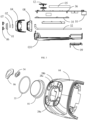
- FIG. 1 is a structural schematic view of a skin care assembly according to an embodiment of the present disclosure.
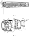
- FIG. 2 is a perspective exploded schematic view of the skin care assembly in FIG. 1 in a direction.
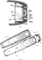
- FIG. 3 is a perspective exploded schematic view of the skin care assembly in FIG. 1 in another direction.
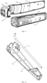
- FIG. 4 is an exploded schematic view of a head portion of the skin care assembly in FIG. 1 in a direction.
- FIG. 5 is a structural schematic diagram of a cold compress component of the skin care assembly in a direction according to an embodiment of the present disclosure.
- a skin care assembly 1 is provided in some embodiments of the present disclosure and includes a cold compress component 01, a refrigeration component 02, a heat sink 03, a first cover 04, and an electrode 06.
- the cold compress component 01 includes a contacting surface 01a, a conducting surface 01b.
- the contacting surface 01a is a portion configured to directly contact a skin.
- a refrigeration side of the refrigeration component 02 is thermally coupled to the conducting surface 01b of the cold compress component 01 to reduce a temperature of the cold compress component 01.
- the heat sink 03 is thermally coupled to a heat-generating side of the refrigeration component 02 to dissipate heat from the refrigeration component 02.
- the first cover 04 is configured to relatively fix the cold compress component 01 to the heat sink 03.
- the electrode 06 is fixed relative to the first cover 04.
- the contacting surface 01a and the conducting surface 01b of the cold compress component 01 are arranged opposite to each other, and the electrode 06 is located on a side where the contacting surface 01a is located.
- the cold compress component 01, the refrigeration component 02 and the heat sink 03 are stacked to form a sandwich structure, which may facilitate an assembly and a heat conduction of the three.
- the cold compress component 01 is in direct contact with the skin.
- the temperature of the cold compress component 01 is reduced by a refrigeration process performed by the refrigeration component 02.
- the heat sink 03 dissipates the heat from the refrigeration component 02.
- the cold compress component 01 is relatively fixed to the heat sink 03 by the first cover 04, such that the heat sink 03 may better cooperate with the refrigeration component 02 to reduce the temperature of the cold compress component 01, reducing a heat return in a short time and increasing a period of the skin care assembly 1 maintaining a temperature balance state.
- the electrode 06 performs a current stimulation and heating for the skin.
- the electrode 06 is relatively fixed to the first cover 04, such that the electrode 06 is close to the skin structurally.
- the electrode 06 cooperates with the cold compress component 01 to achieve a cosmetic effect such as firming the skin and shrinking pores.
- the electrode 06 When the skin care assembly 1 is in operating, the electrode 06 is discharged.
- the electrode 06 may generate a radio frequency or a micro-current.
- the current passes through the skin to stimulate the skin, such that a desired cosmetic effect may be achieved. Since the skin acts as an electrical resistance, a temperature of the skin may be increased.
- the cold compress component 01 and the electrode 06 are fixed relative to the first cover 04.
- the cold compress component 10 and the electrode 06 are both in direct contact with the skin and are adjacent to each other.
- the current of the electrode 06 passing through the skin may cause a muscle having a contraction movement, and the cosmetic effect may be achieved.
- An epidermal temperature and a dermal temperature of the skin may be increased during a discharge process of the electrode 06.
- the temperature of the skin may be increased resulting from a heat generated by skin cells and a heat converted from an electrical energy.
- the cold compress component 01 is configured to reduce a heat generated by the electrode 06 stimulating an epidermis, and reduce a temperature of the epidermis of the skin. In this way, a cold compress and calm effect may be achieved, which may avoid burning the skin due to an excessive temperature, reduce a discomfort feeling in use, and improve a comfort of operating an operating member.
- the refrigeration component 02 performs the refrigeration process for the cold compress component 01, such that the cold compress component 01 may continuously reduce the temperature of the epidermis of the skin.
- a process of hot and cold being alternated may also make the skin expand and contract, enhancing a breath of the skin. In this way, collagen of a dermal layer may be better stimulated to be tightened and regenerated while the skin is protected from a damage, and the skin may be tightened, which may improve the cosmetic effect.
- the skin may be a facial skin.
- a more superficial skin may be the epidermis, and a deeper skin may be a dermis.
- the electrode 06 When operating, the electrode 06 may be discharged and generate the radio frequency or the micro-current, etc., to perform a cosmetic process for the facial skin.
- the electrode 06 may be fixedly mounted on the first cover 04.
- the skin care assembly 1 may be applied in a beauty instrument.
- the number of electrodes 06 may be four.
- the electrodes 06 are arranged on a circumferential side of the cold compress component 01 and spaced from each other. A height of an upper surface of the electrode 06 close to the skin flushes with a height of the contacting surface of the cold compress component 01, that is, the electrodes 06 and the cold compress component 01 may be simultaneously in direct contact with the skin. In this way, the cosmetic effect such as firming the skin and shrinking the pores, etc., may be achieved.
- a material of the cold compress component 01 may be a crystal and/or a metal.
- the cold compress component 01 may be a material having a good thermal conductivity, such as a sapphire, a Topaz, a rock crystal, a glass, or the like, and configured to directly contact the skin and reduce the temperature of the epidermis.
- the cold compress component 01 made of a sapphire material has the good thermal conductivity and is skin-friendly.
- the cold compress component 01 may be in a shape of a circle, an oval, or a polygon.
- the polygon may be, for example, a square, a rectangle, a pentagon, a hexagon, etc.
- the shape of the cold compress component 01 is not specifically limited herein.
- the contacting surface 01a of the cold compress component 01 may have an area between 350 mm 2 and 450 mm 2 , a thickness between 2 mm and 5 mm, and a ratio of the area of the contacting surface 01a of the cold compress component 01to the thickness of the contacting surface 01a of the cold compress component 01 is between 88:1 and 225:1.
- a total power when all electrodes 06 are discharged is between 5 watts and 20 watts.
- a temperature of the dermis of the skin is between 50°C and 70°C.
- An operating power of the refrigeration component 02 is configured to have the temperature of the skin reduced to a range between 15°C and 45°C.
- the electrode 06 may include an arc-shaped body and a fixing portion protruding from the arc-shaped body towards the cold compress component 01, and the first stepped surface 06a is located on a side of the arc-shaped body facing the cold compress component 01.
- Multiple electrodes 06 are spaced from each other, and a circle is defined by arc-shaped bodies of the multiple electrodes 06, which may exactly enclose the contacting surface 01a of the cold compress component 01 or may also partially overlaps with the contacting surface 01a.
- the cold compress component may include the cold compress component 01 and a cold-conducting layer 07.
- the cold-conducting layer 07 is arranged between the cold compress component 01 and the refrigeration component 02 and configured to conduct a heat between the cold compress component 01 and the refrigeration component 02.
- the cold-conducting layer 07 abuts against the cold compress component 01.
- the cold-conducting layer 07 is further arranged between the conducting surface 01b of the cold compress component 01 and the refrigeration side of the refrigeration component 02.
- the conducting surface 01b of the cold compress component may transfer to a side of the cold-conducting layer 07 facing away from the cold compress component and directly contact with the refrigeration side of the refrigeration component 02. Since the cold-conducting layer 07 has a good thermal conductivity, the refrigeration component 02 may efficiently reduce the temperature of the cold compress component 01 through the cold-conducting layer 07.
- the conducting surface 01b of the cold compress component is in direct surface-contact with the refrigeration side of the refrigeration component 02. With a surface-contact manner, the heat conduction may be more sufficient and a conduction effect may be maximized.
- the cold-conducting layer 07 may be made of an aluminum nitride ceramic or other materials having good thermal conductivity. The surface-contact manner may maximize a heat-transferring effect. Both the cold compress component 01 and the cold-conducting layer 07 are made of materials having good heat-transferring performances.
- the cold-conducting layer 07 may be filled with a thermally conductive silicone grease, such that a heat transfer may be more sufficient, a control for the temperature may be smoother, and a feeling of the skin may be more comfortable.
- the skin care assembly 1 may further include a second cover 08, a first mounting plate 35, a second mounting plate 36, an inner housing 11, a button 12, a charging port 10, and a thermally conductive housing 09, or the like.
- the sapphire in some embodiments of the present disclosure may be artificial or natural.
- the skin care assembly 1 may further include a lead wire and a wire groove.
- the lead wire is connected to and fixed on a side of the refrigeration element 02.
- the wire groove is defined in an inner side of the second cover 08 corresponding to the side where the lead wire is arranged of the refrigeration element 02, and defined along an edge of a limiting hole 24.
- lead wires may include at least one lead wire.
- the number of wire grooves is consistent with the number of the lead wires, and the lead wires are accommodated in the wire grooves in a process of assembling the skin care assembly 1, such that the refrigeration component 02 and the heat sink 03 may be connected and fixed together.
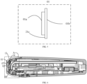
- a skin care assembly 1 is also provided in the present disclosure, as shown in FIGS. 2 and 3 .
- the skin care assembly 1 may include the operating member, a mounting bracket 03, and a circuit board.
- the operating member includes a cold compress component 01 and a refrigeration component 02 located at a head portion of the skin care assembly 1, and has a contacting surface 01a configured to directly contact the skin and reduce a temperature of the skin.
- the mounting bracket 03 includes a first mounting position and a second mounting position. The operating member is fixed to the mounting bracket 03 through the first mounting position, and the circuit board is fixed to the mounting bracket 03 through the second mounting position.
- the operating member is located at the head portion of the skin care assembly 1, and the mounting bracket 03 extends from the head portion of the skin care assembly 1 to a tail of the beauty instrument.
- Both the operating member and the circuit board are mounted on the mounting bracket 03, such that the assembly of each component of the skin care assembly 1 may be more centralized. In this way, a convenient assembly may be achieved, and an overall structure of the skin care assembly 1 may be more compact, such that a volume of the skin care assembly 1 may be reduced.
- the mounting bracket 03 may also serves as a heat sink to dissipate a heat from the beauty instrument while the mounting bracket 03 is mounted with various components.
- the mounting bracket 03 is in tight contact with a component such as the operating member in the beauty instrument, which is conducive to a sufficient and uniform heat dissipation.
- the mounting bracket 03 may absorb the heat in the whole beauty instrument, making the heat dissipation more efficient.
- the mounting bracket 03 extending to the tail of the beauty instrument allows the heat to stay for a longer time and not to backtrack in a short time, which increasing a refrigeration period of the operating member.
- the skin care assembly may include the thermally conductive housing 09, and the mounting bracket 03 includes a third mounting position configured to mount the thermally conductive housing 09.
- a side surface of the mounting bracket 03 defines a groove, and both the second mounting position and the third mounting position are arranged or defined in the groove.
- the second mounting position in the groove, may be located at a position having a depth different from a depth of a position where the third mounting position is located, such that the circuit board and the thermally conductive housing 09 may be stacked.
- the second mounting position is farther from a bottom of the groove than the third mounting position.
- a ratio of a distance from the second mounting position to the bottom of the groove to a distance from the third mounting position to the bottom of the groove may be between 1.5 and 3 times.
- the skin care assembly includes the first mounting plate 36 and the button 12.
- the button 12 is arranged on the first mounting plate 36.
- a side wall of the groove is arranged with a step, and the circuit board is fixed in the groove through the step.
- the first mounting plate 36 is fixed to the side wall of the groove, and is located on a side of the circuit board facing away from the bottom of the groove.
- the skin care assembly includes a second mounting plate 35.
- the circuit board is mounted on the second mounting plate 35, the second mounting plate 35 is mounted on the step, and the second mounting plate 35 is spaced from the bottom of the groove.
- the first mounting plate 36 extends to the tail of the skin care assembly, and an end of the first mounting plate 36 away from the operating member is defined with a charging port 10 configured to be connected to the circuit board.
- first mounting board 36 and the second mounting board 35 themselves may also be circuit boards.
- a ratio of a length of the second mounting plate 35 to a length of the mounting bracket 03 is between 1.2 and 2.
- the charging port 10 is spaced from the mounting bracket 03 by a certain distance, and the distance is between 1 cm and 3 cm.
- the mounting bracket 03 defines a receiving cavity.
- the receiving cavity is defined on a side surface of the first mounting position and configured to accommodate a part of the lead wires in the skin care assembly.
- the mounting bracket 03 extends from the head portion of the skin care assembly 1 to the tail of the skin care assembly 1.
- the operating member cools down the skin or a surface layer of an adjacent tissue of the skin, and a depth of action of an electricity, a magnetism, or an electromagnetic emitted by the electrodes on the skin is greater than that on the surface layer.
- an area of the contacting surface 01a is greater than an area where the electrodes act on the skin.
- the skin care assembly 1 further includes the charging port 10.
- the charging port 10 is arranged at an ending end of the second mounting plate 36 and exposed out of the skin care assembly 1.
- the second mounting plate 36 may be configured to be mounted with a component or an element necessary for the skin care assembly 1 such as the circuit board, a battery, etc.
- the skin care assembly 1 may be used when powered on or after charged. When used after charged, the skin care assembly 1 charges for the battery by the charging port 10 being connected to an external power cord.
- the charging port 10 When the skin care assembly 1 is used when powered on, the charging port 10 may generate a certain impedance due to adopting a point-contact manner inside the charging port 10, and heat may be generated when a current passes through the charging port 10.
- the charging port 10 is defined at an end of a mounting plate and away from the heat sink 03, which may avoid the heat generated by the charging port 10 backtracking to the skin care assembly 1 or even the operating member.
- the heat generated by the charging port 10 backtracking to the skin care assembly 1 or the operation head may affect a refrigeration effect of the refrigeration component 02, thereby affecting the cosmetic effect.
- the skin care assembly 1 further includes an airflow driver.
- the airflow driver is arranged opposite to the heat sink and configured to drive airflow near the heat sink to flow so as to enhance a heat-dissipating effect.
- the airflow driver may be arranged on a position of the skin care assembly 1 close to the head portion.
- the airflow driver drives the airflow to flow from the head portion to the tail of the skin care assembly 1 and be discharged from an air outlet at the tail of the skin care assembly 1.
- the airflow driver is a fan, and the fan is located at the head portion and blows air against the heat sink 03.
- the tail of the skin care assembly 1 defines the air outlet corresponding to a tail of the heat sink 03 to discharge the airflow carrying heat.
- the heat sink 03 extends from the head portion of the skin care assembly 1 to the tail of the skin care assembly 1.
- An end of the heat sink 03 located at the tail of the skin care assembly 1 is spaced from the tail by a gap, and a size of the gap is less than one third of a length of the skin care assembly 1.
- the heat sink 03 includes the second cover 08 and a heat-dissipating body 031.
- the second cover 08 is disposed between the heat-dissipating body 031 and the first cover 04, and fixed to the heat-dissipating body 031.
- the first cover 04 is fixed on the second cover 08.
- the second cover 08 may be a light-transmitting plate 13.
- the second cover body 08 further defines the limiting hole 24.
- a position of the limiting hole 24 corresponds to a position of a first opening 50 of the first cover 04.
- the limiting hole 24 is fluidly communicated with the first opening 50 of the first cover 04.
- a part of the refrigeration component 02 is arranged in the limiting hole 24, and an edge of the refrigeration component 02 is 0.5-1 mm away from an edge of the limiting hole 24.
- a ratio of an area of the limiting hole 24 to an area of the first opening 50 of the first cover 04 is between 0.8 and 1.2.
- FIG. 12 is a structural schematic view of a heat-dissipating body of the skin care assembly in a direction according to an embodiment of the present application.
- FIG. 13 is a structural schematic view of the heat-dissipating body shown in FIG. 11 in a second direction.
- FIG. 14 is a structural schematic view of the heat-dissipating body shown in FIG. 11 in a third direction.
- a skin care assembly 1 is further provided in the present disclosure and includes a heat pipe 32 and a heat-dissipating body 031.
- An end of the heat pipe 32 is thermally coupled to an end of the heat-dissipating body 031 close to the second cover 08, and the other end of the heat pipe 32 extends along a direction away from the refrigeration component 02 and is thermally coupled to the heat-dissipating body 031.
- the heat-dissipating body 031 itself has a heat-dissipating function, and the heat pipe 32 assists the heat-dissipating body 031 to dissipate the heat, thereby improving a heat-dissipating efficiency of the heat-dissipating body 031.
- the end of the heat pipe 32 is thermally coupled to the end of the heat-dissipating body 031 close to the second cover 08, and the other end of the heat pipe 32 extends along the direction away from the refrigeration component 02, such that a path for transferring the heat may be long enough to avoid the heat backtracking to the head portion of the beauty instrument in a short time, and a refrigeration period of the beauty instrument may be increased.
- a section of the heat pipe 32 is bent to form a bent portion, and the bent portion abuts against the end of the heat-dissipating body 031 close to the second cover 08.
- An inside of the heat pipe 32 has a hollow and closed structure, with liquid filled inside. The heat pipe 32 is not filled up with the liquid.
- the heat-dissipating body 031 defines an escape groove 03c.
- the heat pipe 32 is arranged along an inner wall of the escape groove 03c, at least partially embedded in the escape groove 03c, and welded to the inner wall of the escape groove 03c.
- An end of the heat pipe 32 away from the bent portion extends to an ending end of the heat-dissipating body 031, such that a contact between the 32 and the heat-dissipating body 031 may be more sufficient, which may improve a heat-dissipating performance of the heat sink 03.
- a contacting portion 03b is arranged on a side surface of the heat-dissipating body 031 close to the refrigeration component 02.
- a position of the contacting portion 03b corresponds to the position of the limiting hole 24.
- the heat-generating side of the refrigeration component 02 may be thermally coupled to the contacting portion 03b through the limiting hole 24.
- a part of the contacting portion 03b is located in the limiting hole 24, attached to the heat-generating side of the refrigeration element 02, and fixed relative to the heat-generating side of the refrigeration element 02.
- the heat-dissipating body 031 is made of aluminum by means of integral molding. An end of the heat-dissipating body 031 away from the escape groove 03c has a heat-dissipating fin structure.
- FIG. 18 is an exploded schematic view of the head portion of the skin care assembly according to another embodiment of the present disclosure.
- FIG. 19 is a structural schematic view of a side of a light-transmitting plate close to a phototherapy lamp plate of the skin care assembly according to another embodiment the present disclosure.
- FIG. 20 is a cross-sectional schematic view of the skin care assembly according to another embodiment of the present disclosure.
- FIG. 21 is an exploded schematic view of the first cover, the light-transmitting plate, the phototherapy lamp plate, and a first bolt of the skin care assembly according to another embodiment of the present disclosure.
- FIG. 19 is a structural schematic view of a side of a light-transmitting plate close to a phototherapy lamp plate of the skin care assembly according to another embodiment the present disclosure.
- FIG. 20 is a cross-sectional schematic view of the skin care assembly according to another embodiment of the present disclosure.
- FIG. 21 is an exploded schematic view of the first cover, the light-transmitting plate, the phototherapy lamp plate, and
- FIG. 22 is a cross-sectional schematic view of an assembly of the first cover, the light-transmitting plate, the phototherapy lamp plate, and the first bolt of the skin care assembly according to another embodiment of the present disclosure.
- FIG. 23 is a structural schematic view of the first cover, the second cover, and the inner housing of the skin care assembly according to an embodiment of the present disclosure.
- the skin care assembly may further include a phototherapy lamp board 14, multiple phototherapy lamps 25 are arranged on a side of the phototherapy lamp board 14 close to the first cover 04, and an escape hole 29 is defined in a center of the phototherapy lamp board 14.
- the multiple phototherapy lamps 25 are arranged around the escape hole 29, and may exactly be covered by a projection of the cold compress component 01 in a direction perpendicular to the contacting surface 01a.
- the refrigeration component 02 and the cold-conducting layer 07 may pass through the escape hole 29 to be directly contacted with the cold compress component 01.
- the phototherapy lamp board 14 is arranged opposite to the heat sink 03, and a side of the phototherapy lamp board 14 without the phototherapy lamps 25 is abutted against and thermally coupled to the heat sink 03.
- the escape hole 29 has a position-limiting action on a first limiting portion 30 protruding from the heat sink 03, such that the phototherapy lamp board 14 and the heat sink 03 may be fixed relative to each other.
- the first limiting portion 30 is thermally coupled to the refrigeration component 02.
- the light-transmitting plate 13 may be arranged between the phototherapy lamp plate 14 and the first cover 04.
- a second through hole 24 is defined in a center of the light-transmitting plate 13 and opposite to the escape hole 29.
- Several light-transmitting portions 27 are defined around the second through hole 24.
- the light-transmitting portions 27 are defined corresponding to the phototherapy lamps 25, and may exactly be covered by the projection of the cold compress component 01 in the direction perpendicular to the contacting surface 01a.
- the light-transmitting portions 27 are covered with light-transmitting materials, and light emitted by the phototherapy lamps 25 may pass through the light-transmitting portions 27 and be mapped to the cold compress component 01.
- the refrigeration component 02 and the cold-conducting layer 07 may pass through the second through hole 24 to be directly contacted with the cold compress component 01.
- the second through hole 24 may have a position-limiting action on the refrigeration component 02.
- the phototherapy lamp board 14 defines multiple first fixing holes 26.
- the first fixing holes 26 are located opposite to third fixing holes 28d in the first cover 04, and configured to fix the phototherapy lamp board 14 relative to the first cover 04.
- the phototherapy lamp board 14, the first cover 04, and the light-transmitting plate 13 may be relatively fixed in a way of snapping, latching, mortising, or thread-bolt connecting.
- a connection manner provided in the embodiment is the thread-bolt connecting.
- An inner wall of the first fixing hole 26 and an inner wall of the third fixing hole 28d also define threads corresponding to a first bolt 16.
- Several first bolts 16 may pass through the first fixing holes 26 and the third fixing holes 28d to have the phototherapy lamp board 14 and the first cover 04 relatively fixed.
- the light-transmitting plate 13 defines several second fixing holes 23, and the number of the second fixing holes 23 is the same as the number of the first fixing holes 26, the number of the third fixing holes 28 d, and the number of the first bolts 16.
- a side of the first cover 04 close to the light-transmitting plate 13 defines a sinking groove 31, and a shape and an outer diameter of the sinking groove 31 are approximately the same as those of the second fixing holes 23. That is, the second fixing holes 23 may have a position-limiting action on the sinking groove 31.
- the third fixing hole 28d penetrated through the sinking groove 31, such that the phototherapy lamp board 14, the light-transmitting board 13, and the first cover 04 may be relatively fixed by the first bolts 16 in a sequence as above.
- the phototherapy lamps 25 may be LED light-emitting lamp beads, and light emitted by the phototherapy lamps 25 exiting to the cold compress component 01 through the light-transmitting portions 27 may appear as red light, which may generate an effect of performing a phototherapy for the skin. Further, the phototherapy lamps 25 may also have other functions, such as a hair removal.
- the light-transmitting materials covered on the light-transmitting portions 27 may be mostly organic or inorganic materials with good light-transmitting performances, such as various optical plastics, silicate glasses, or the like.
- the light-transmitting plate 13 may not be disposed between the phototherapy lamp plate 13 and the first cover 04, and the light emitted by the phototherapy lamps 25 may be directly mapped to the cold compress component 01.
- FIG. 15 is a schematic view of an assembly of the first cover, a second cover, and a heat sink of the skin care assembly according to an embodiment of the present disclosure.
- FIG. 16 is a cross-sectional schematic view of the skin care assembly according to an embodiment of the present disclosure.
- FIG. 17 is a partial enlarged view of a position B in FIG. 15 .
- the skin care assembly 1 includes a cold compress component 01, a refrigeration component 02, a heat sink 03, a first cover 04, a pulse-generating circuit 05, and an electrode 06.
- the cold compress component 01 includes a contacting surface 01a and a conducting surface 01b, and the contacting surface 01a is configured to directly contact the skin.
- a refrigeration side of the refrigeration component 02 is thermally coupled to the conducting surface 01b of the cold compress component 01 to reduce a temperature of the cold compress component 01.
- the heat sink 03 is thermally coupled to a heat-generating side of the refrigeration component 02 to dissipate heat from the refrigeration component 02.
- the first cover 04 is configured to relatively fix the cold compress component 01 to the heat sink 03, and at least partially wrap or accommodate the cold compress component 01 and the heat sink 03.
- the pulse-generating circuit 05 is arranged on a side of the heat sink 03 facing away from the refrigeration component and configured to generate an electric/magnetic pulse.
- the electrode 06 is relatively fixed to the first cover 04 and protrudes relative to the first cover 04.
- the electrode 06 is connected to the pulse-generating circuit. When the electrode 06 directly contacts the skin, the pulse-generating circuit 05 may generate the electric/magnetic pulse to maintain the skin.
- a cold-conducting layer may be arranged between the heat-generating side of the refrigeration component 02 and the heat sink 03, and filled with a thermally conductive silicone grease, so as to have a more sufficient heat transfer and also make a control for the temperature smoother. In this way, a feeling of the skin may be more comfortable.
- both the cold compress component 01 and the electrode 06 are fixed on the first cover 04, such that the cold compress component 01 and the electrode 06 may be better fixed, increasing a structural stability thereof.
- both the refrigeration component 02 and the pulse-generating circuit 05 are arranged on the heat sink 03, and the pulse-generating circuit 05 is located on the side of the heat sink 03 facing away from the refrigeration component, which improves the heat-dissipating efficiency of the care component 1 with reducing an interference of the heat generated by the refrigeration component 02 and the pulse-generating circuit 05 on the cold compress component 01.
- the electrode 06 is fixed on the first cover 04, such that a structure for mounting the electrode 06 may be avoided to be processed on a component such as the cold compress component 01, reducing a processing cost accordingly.
- the first cover 04 may include two side surfaces, i.e., an outer side surface and an inner side surface.
- the outer side surface is exposed to air and is configured to fix the electrode 06 and the cold compress component 01
- the inner side surface is configured to wrap or accommodate the refrigeration component 02 and partially wrap or accommodate the heat sink 03 and the cold compress component 01.
- four first mounting holes 04b are defined in the inner side surface of the first cover 04 and configured to fix the first cover 04.
- the heat sink 03 includes a first end, and a first end of the heat sink 03 defines four second mounting holes.
- the first mounting holes 04b in the cover body 04 are assembled corresponding to the four second mounting holes in the heat sink 03 and fixed by screws. Subsequently, the first end of the heat sink 03 is wrapped or accommodated by the first cover 04 in an inner side of the first cover 04.
- the heat-generating side of the refrigeration component 02 is connected and thermally coupled to the first end of the heat sink 03, and both the heat-generating side of the refrigeration component 02 and the first end of the heat sink 03 are wrapped or accommodated by the first cover 04.
- the refrigeration side of the refrigeration component 02 is thermally coupled to the conducting surface 01b of the cold compress component 01, and both the refrigeration side of the refrigeration component 02 and the conducting surface 01b of the cold compress component 01 are wrapped or accommodated by the first cover 04.
- the contacting surface 01a of the cold compress component 01 and the electrode 06 are both located on an outer side of the first cover 04, such that the skin care assembly 1 may perform an electromagnetic pulse therapy for the skin through the electrode 06 during operating while also protecting the skin by reducing the temperature of the skin through the cold compress component 01, so as to improve a skin care effect of the skin care assembly 1 for the skin.
- a first accommodating cavity is defined between the first end of the heat sink 03 and a second end of the heat sink 03.
- the second end of the heat sink 03 described above is an end of the heat sink 03 connected to the first end of the heat sink 03 and away from the heat-generating side of the refrigeration component 02.
- a supporting frame is arranged in the first accommodating cavity.
- the pulse-generating circuit 05 is fixed on the supporting frame of heat sink 03. When the skin care assembly 1 is in operating, the heat generated by the refrigeration component 02 and the pulse-generating circuit 05 is directly conducted to the heat sink 03 and dissipated through the heat sink 03 based on a high heat-dissipating performance of the heat sink 03.
- the first cover 04 may include the two side surfaces, i.e., the outer side surface and the inner side surface.
- the inner side surface and the outer side surface are fluidly communicated to each other through the first opening 50.
- a mounting platform is arranged on the outer side of the first cover 04.
- the cold compress component 01 is fixed on the mounting platform in the outer side of the first cover 04 through being pressed by the electrode 06.
- the inner side of the first cover 04 defines a first receiving cavity.
- a part of components including the heat sink 03 of the skin care assembly 1 are wrapped or accommodated by the first cover 04 or partially wrapped or accommodated in the first receiving cavity.
- the conducting surface 01b of the cold compress component 01 passes through the first opening 50 between the inner side surface and outer side surface of the first cover 04 and abuts against one side of the heat sink 03.
- FIG. 6 is a cross-sectional schematic view of the skin care assembly according to an embodiment of the present disclosure.
- FIG. 7 is a partial enlarged view of a position A in FIG. 6 .
- FIG. 8 is an exploded schematic view of an electrode and a first cover of the skin care assembly in a direction according to some embodiments of the present disclosure.
- FIG. 9 is a cross-sectional schematic view of an assembling position of the electrode of the skin care assembly according to some embodiments the present disclosure.
- the electrode 06 is configured in a crescent shape and has two special ends.
- An end of the two special ends is a body portion configured to maintain the skin by adopting the electric/magnetic pulse during the electrode 06 being in operating.
- the other end of the two special ends is a fixing portion.
- the fixing portion is connected to the first cover 04, such that the electrode 06 may be fixed on the mounting platform in the outer side of the first cover 04.
- the fixing portion faces towards the mounting platform in the outer side of the first cover 04 during being mounted.
- the fixing portion includes at least one mounting column 06a.
- At least one mounting hole 28c is defined on the mounting platform of the first cover 04.
- the electrode 06 may be fixed to the first cover 04 through the at least one mounting column 06a being mounted in the at least one mounting hole 28c.
- a height of the electrode 06 protruding relative to the first cover 04 is between 0mm-20mm.
- a first sinking hole 28a is defined in the mounting platform of the first cover 04, and slightly lower than the mounting platform.
- the first sinking hole 28a has a shape corresponding to the shape of the electrode 06 and is configured to fix the electrode 06 on the mounting platform and preventing the electrode 06 from being shaked or shifted.
- a gasket 34 for sealing and absorbing a shock may be arranged between the first cover 04 and the electrode 06.
- a second sinking hole 28b configured to accommodate the gasket 34 is defined in the second sinking hole 28b of the mounting platform.
- the second sinking hole 28b has a shape corresponding to a shape of the gasket 34.
- At least one third through hole 34a is defined in the gasket 34.
- the number of the at least one third through hole 34a matches the number of the at least one mounting column 06a, and a shape of the at least one third through hole 34a is adapted to a cross-sectional shape of the at least one mounting column 06a, such that the at least one mounting column 06a passes through the at least one third through hole 34a to fix the gasket 34 between the first cover 04 and the electrode 06.
- other corresponding fixed facilities may also be arranged on the gasket 34, the electrode 06, and the first cover 04 to prevent the gasket 34 from being shifted.
- the gasket 34 may be made of a material such as a silica gel, etc., which may be capable of occurring an elastic deformation and have a greater friction coefficient.
- the shape of the gasket 34 may be adapted to the shape of the electrode 06, and has a size less than a size of the shape of the electrode 06.
- the cold compress component 01 is located in the first opening 50 of the first cover 04.
- the cold compress component 01 has a first radial size and a second radial size different from the first radial size at positions corresponding to different thicknesses.
- the first opening 50 has a third radial size and a fourth radial size different from the third radial size at positions corresponding to different depths.
- a portion of the cold compress component 01 having the first radial size is closer to the cold-conducting layer 07 than a portion of the cold compress component 01 having the second radial size.
- a portion of the first opening 50 having the third radial size is closer to the cold-conducting layer 07 than a portion of the first opening 50 having the fourth radial size.
- the first radial size is less than the third radial size
- the second radial size is less than the fourth radial size
- the second radial size is greater than the third radial size.
- a first stepped surface 21c is arranged between the portion having the first radial size and the portion having the second radial size of the cold compress component 01.
- a second stepped surface 22a is arranged between the portion having the third radial size and the portion having the fourth radial size of an inner side of the first opening 50 of the first cover 04.
- An outer side of the first opening 50 of the first cover 04 is arranged with the mounting platform.
- the electrode 06 is mounted on the mounting platform on the outer side of the first cover 04, and is configured to maintain the skin.
- the refrigeration component 02, the cold-conducting layer 07, and the cold compress component 01 abut against the first end of the heat sink 03 in sequence, and are fixed between the first cover 04 and the first end of the heat sink 03 through the second stepped surface 22a in the inner side of the first cover 04 abutting against and being attached to the first stepped surface 21c of the cold compress component 01.
- the contacting surface 01a of the cold compress component 01 passes through the first opening 50 of the first cover 04 and is located on the outer side of the first cover 04, configured to assist the electrode 06 to maintain the skin.
- a first sealing component 33 for sealing and absorbing the shock may be arranged between the first opening 50 of the first cover 04 and the cold compress component 01.
- the first sealing component 33 is arranged between the first stepped surface 21c and the second stepped surface 22a.
- the first sealing component 33 may be deformed by a force, such that an inside of the machine body of the skin care assembly 1 may be isolated from an external environment.
- the first sealing component 33 may serve as a buffer when the machine body is bumped or dropped.
- a shape of the first sealing component 33 may be adapted to a shape of the first stepped surface 21c.
- other corresponding fixed facilities may also be arranged between the first sealing component 33, the cold compress component 01, and the first cover 04 to prevent the first sealing component 33 from being shifted.
- the first sealing component 33 may be made of the material such as the silica gel, etc., which may be elastically deformed and have the greater friction coefficient.
- FIG. 10 is a structural schematic view of the first cover and an inner housing of the skin care assembly in a direction according to some embodiments the present disclosure.
- FIG. 11 is a structural schematic view of the first cover and the inner housing of the skin care assembly in another direction according to some embodiments the present disclosure.
- the skin care assembly 1 may further include the inner housing 11 and an outer housing 37.
- the skin care assembly 1 may be at least partially arranged in the inner housing 11.
- the heat sink 03 is partially arranged in the inner housing 11 and fixed relative to the inner housing 11, and the inner housing 11 is partially arranged in an inner side of the outer housing 37.
- a second fastener 37b is fixed on the outer housing 37, and a first fastener 04d is fixed on the first cover 04. The second fastener 37b is snapped to the first fastener 04d.
- the first fastener 04d is fixed on the first cover 04
- the second fastener 37b is fixed on the outer housing 37, such that it may be more convenient for the skin care assembly 1 to be mounted and aligned and have an accessory replaced when the skin care assembly 1 is assembled.
- a part of the second fastener 37b is arranged on a side of the outer housing 37 close to a thermally coupling surface of the heat sink 03, i.e., a side where a cavity opening of an empty cavity for accommodating the heat sink 03 of the outer housing 37 is located, and close to a side wall 04c of the first cover 04.
- the first cover 04 includes the side wall 04c corresponding to the outer housing 37, and the first fastener 04d is arranged on two side walls 04c of the first cover 04.
- the first fastener 04b may define a bayonet, an edge of the bayonet may be arranged with an inclined surface 04e.
- the second fastener 37b may include a hook. Under a guide of the inclined surface 04e, the hook of the second fastener 37b may enter into the bayonet of the first fastener 04b to complete a snap connection. In this way, the side walls 04c of the first cover 04 may be assembled with the outer housing 37.
- the side walls 04c may be arranged with multiple first fasteners 04d and inclined surfaces 04e.
- the inner side of the outer housing 37 may be also arranged with the second fasteners 37b corresponding to the first fasteners 04d in the number and positions. No specific restrictions are made herein.
- the first fasteners 04d on the side walls 04c and the second fasteners 37b on the inner side of the outer housing 37 may be correspondingly arranged asymmetrically.
- an upper side and a lower side are distinguished based on the button 12, the numbers of the first fasteners 04d and the second fasteners 37b close to the upper side are different from those of the ones close to the lower side, such that front and back for mounting of the side walls 04c of the first cover 04 and front and back for mounting of the outer housing 37 may be clearly distinguished, and a foolproof effect may be achieved.
- the skin care assembly 1 provided in some embodiments of the present disclosure further includes a third fastener 11b and a fourth fastener 37a.
- Fourth fasteners 37a are fixed on an edge of the outer housing 37, and third fasteners 11b are fixed on edges of two side surfaces of the inner housing 11.
- the third fasteners 11b are snapped to the fourth fasteners 37a.
- the third fasteners 11b are arranged on the inner housing 11, and the fourth fasteners 37a are arranged on the outer housing 37, such that it may be more convenient for the skin care assembly 1 to be mounted and aligned and have the accessory replaced when the skin care assembly 1 is assembled.
- the third fasteners 11b are arranged on the edges of the two side surfaces of the inner housing 11, generally by arranging several third fasteners 11b from a head portion of the inner hosing 11 to a tail of the inner housing 11.
- the fourth fasteners 37a are arranged on the inner side of the outer housing 37 at positions corresponding to the third fasteners 11b. Since a shape of the outer housing 37 fit for shapes of the two side surfaces of the inner housing 11, several third fasteners 11b are arranged along the edge of the outer housing 37 from a head portion of the outer housing 37 to a tail of the outer housing 37.
- the third fasteners 11b may include bayonets, edges of the bayonets may be arranged with inclined surfaces.
- the second fasteners 37b may include hooks. Under guides of the inclined surfaces, the hooks of the second fasteners 37b may enter into the bayonets of the first fasteners 11b to complete a snap connection. In this way, the two side surfaces of the inner housing 11 may be assembled with the outer housing 37.
- the edges of the two side surfaces of the inner housing 11 may be arranged with multiple third fasteners 11b and inclined surfaces.
- the inner side of the outer housing 37 may be also arranged with the fourth fasteners 37a corresponding to the third fasteners 11b in the number and positions. No specific restrictions are made herein.
- the third fasteners 11b on the edges of the two side surfaces of the inner housing 11 and the fourth fasteners 37a on the inner side of the outer housing 37 may be correspondingly arranged asymmetrically.
- a front side and a rear side are distinguished based on the button 12, the numbers of the third fasteners 11b and the inclined surfaces arranged on the edges of the side surfaces of the inner housing 11 on the front side, and the fourth fasteners 37a are different from those on the rear side. In this way, front and back for mounting may be clearly distinguished, and the foolproof effect may be achieved.
- FIG. 23 is a structural schematic view of the first cover, the second cover, and the inner housing of the skin care assembly according to an embodiment of the present disclosure.
- FIG. 24 is a structural schematic view of the inner housing of the skin care assembly according to an embodiment of the present disclosure.
- FIG. 25 is a structural schematic view of the second cover and the heat sink of the skin care assembly according to an embodiment of the present disclosure.
- the first cover 04 includes a first panel portion 48 parallel to the contacting surface of the cold compress component 01, and a first side wall extending along a direction from a side edge of the first panel portion 48 towards the heat sink 03, such that the first receiving cavity may be defined in the inner side of the first cover 04.
- the first opening 50 is defined in the first panel portion 48, the contacting surface of the cold compress component 01 is exposed to an outer side of the first receiving cavity from the first opening 50 to directly contact the skin.
- the second cover 08 includes a second panel portion 49 parallel to the first panel portion 48, and a second side wall 47 extending along a direction from a side edge of the second panel portion 49 towards the heat sink 03.
- a second receiving cavity is defined in the inner side of the second cover 08.
- the second panel portion 49 defines a second opening 51.
- the conducting surface of the heat sink 01 is exposed to the second receiving cavity through the second opening 51, so as to be thermally coupled to the refrigeration component 02.
- the second cover 08 is embedded in the first receiving cavity of the first cover 04 and fixed to the first cover 04.
- the cold compress component 01 is fixed between the first panel portion 48 of the first cover 04 and the second panel portion 49 of the second cover 08.
- the skin care assembly 1 in some embodiments of the present disclosure further includes a first mounting column 41 and defines a first mounting hole 42a.
- the first mounting column 41 is arranged in the second receiving cavity of the second cover 08.
- a mounting ear 42 extends radially from a side edge of the heat sink 03, the first mounting hole 42a is defined in the mounting ear 42.
- the number of the mounting ear 42 corresponds to the number of the first mounting column 41.
- An end of the heat sink 03 thermally coupled to the refrigeration component 02 is partially embedded in the second receiving cavity of the second cover 08 and fixed to the second cover 08.
- an end of the first mounting column 41 close to the first mounting hole 42a defines a threaded hole, and a first stud penetrates into the threaded hole at the end of the first mounting column 41 from the first mounting hole 42a of the mounting ear 42 to screw the heat sink 03 to the second cover 08.
- the first stud passes through the first mounting hole 42a and be connected to the threaded hole at the end of the first mounting column 41 from a side of the mounting ear 42 facing away from the second cover 08.
- the skin care assembly 1 in some embodiments of the present disclosure further defines an accommodating cavity 53 and an opening 52.
- the accommodating cavity 53 is defined in the inner side of the inner housing 04, and extends from the head portion of the inner housing 11 to the tail of the inner housing 04.
- the opening 52 is defined at an end of the accommodating cavity 53 close to the refrigeration component 02.
- the heat sink 03 is partially embedded in the accommodating cavity 53 through the opening 52.
- the end of the heat sink 03 thermally coupled to the refrigeration component 02 is partially exposed to an outer side of the accommodating cavity 53 through the opening 52, and a portion of the heat sink 03 partially exposed to the outer side of the accommodating cavity 53 through the opening 52 is partially embedded in the first receiving cavity of the first cover 04.
- the skin care assembly 1 in some embodiments of the present disclosure further includes a second mounting column 38, and defines a first through hole 39 and a second mounting hole 40.
- the second mounting column 38 is arranged in the first receiving cavity of the first cover 04, the first through hole 39 corresponding to the second mounting column 38 is defined in the second receiving cavity of the second cover 08, and the second mounting hole 40 corresponding to the second mounting column 38 is defined in the inner housing 11.
- a diameter of the first through hole 39 is close to and slightly greater than a diameter of the second mounting column 38.
- the second mounting column 38 may be arranged in the first receiving cavity of the first cover 04 at a transiting position between the first panel portion 48 and the first side wall 46.
- the first through hole 39 may be arranged in a transiting position between the second panel portion 49 and the second side wall 47, so as to cooperate with the second mounting hole 40.
- the second mounting hole 40 is defined in a wall of the accommodating cavity of the inner housing 11 and close to the opening 52.
- a mounting rib 40a is arranged in the accommodating cavity 53 of the inner housing 11 and extends from the opening 52 to a tail of the accommodating cavity 53.
- a mounting groove 40b recessed along a direction towards the accommodating cavity 53 is defined in an outer side of the inner housing at a position corresponding to the mounting rib 40a. Due to existence of the mounting rib 40a and the mounting groove 40b, the second mounting hole 40 is close to a top end of the second mounting column 38 and exposed to an end of the mounting rib 40a close to the opening 52, and a bottom of the second mounting hole 40 is exposed to an end of the mounting groove 40b close to the opening 52.
- an end of the second mounting column 38 close to the second mounting hole 40 defines a threaded hole
- a second stud may penetrate into a top end of the second mounting hole 40 and pass out a bottom end of the second mounting hole 40, and be screwed to the threaded hole in the end of the second mounting column 38 passing through the first through hole 39, such that the first cover 04 and the inner housing 11 are fixed.
- the skin care assembly 1 in some embodiments of the present disclosure further includes a third mounting column 43, and defines a third mounting hole 44.
- the third mounting column 43 is arranged in the first receiving cavity of the first cover 04, and the third mounting hole 44 corresponding to the third mounting column 43 is defined in the second panel portion 49 of the second cover 08.
- An end of the third mounting column 43 close to the third mounting hole 44 defines a threaded hole.
- a third stud may pass through the third mounting hole 44 and be screwed to the threaded hole in the end of the third mounting column 43, such that the second cover 08 may be fixed to the first receiving cavity of the first cover 04.
- the cold compress component 01 may be fixed to the first receiving cavity of the first cover 04, and located between the first cover 04 and the second cover 08.
- the third mounting hole 44 penetrates through the second panel portion 49 and fluidly communicate to the second receiving cavity of the second cover 08.
- the conducting surface of the cold compress component 01 may be exposed through the second through hole 24 and thermally coupled to the refrigeration component 02.
- FIG. 26 is a structural schematic view of a second sealing component and the second cover of the skin care assembly according to an embodiment of the present disclosure.
- the skin care assembly 1 in some embodiments of the present disclosure may further include a second sealing component 45 arranged on the second cover 08.
- the second sealing component 45 is attached to a surface of the transiting portion between the second panel portion 49 and the second side wall 47 of the second cover 08 and tightly attached to the second cover 08.
- the second sealing component 45 may be deformed due to being extruded by the first cover 04, such that a gap between the second cover 08 and the first receiving cavity of the first cover 04 may be blocked, preventing water and oil from entering into the second receiving cavity of the second cover 08 and affecting a stability of an interior circuit.
- a material of the second sealing component 45 may be an elastic material such as the silica gel, a latex, or the like, and may also be a poured liquid glue.
- the skin care assembly 1 further includes the first cover 04, at least partially located between the first cover 04 and the heat sink 03.
- the second cover 08 is fixed to the heat sink 03, and the cover 04 is fixed to the second cover 08.
- the cold compress component 01 tightly presses the cold-conducting layer 07 and the refrigeration component 02 against the heat sink 03 in a first direction.
- the second cover 08 is sleeved in the inner side of the first cover 04 and is at least partially located between the first cover 04 and the heat sink 03, and configured to limit a shit of the heat sink 03 in the first direction.
- the first direction mentioned herein is a direction perpendicular to both the first cover 04 and the second cover 08.
- Four first positioning holes corresponding to the first mounting holes and the second mounting holes are defined in the second cover 08.
- Four positioning columns 04a are defined in the inner side of the first cover 04.
- the first mounting holes 04b of the first cover 04 are defined in the four positioning columns 04a. During mounting, the four positioning columns on the first cover 04 pass through the first positioning holes in the second cover 08 and abut against the second positioning hole in the heat sink 03, and are finally fixed by means of screws.
- the second cover 08 may be fixed between the first cover 04 and the heat sink 03.
- the cold compress component 01 which has been fixed on the first cover 04 passes through the first cover 04 and presses the cold-conducting layer 07 and the refrigeration component 02 tightly to the heat sink 03 along the direction perpendicular to both the first cover 04 and the second cover 08.
- the second cover body 08 further defines a limiting hole.
- the limiting hole is located at the opening of the first cover 04 and communicated fluidly to the opening.
- a part of the refrigeration component 02 is arranged in the limiting hole, and an edge of the refrigeration component 02 is 0.5-1 mm away from an edge of the limiting hole.
- a region of the heat sink 03 corresponding to the refrigeration component 02 defines a groove. The groove corresponds to the limiting hole.
- a part of the refrigeration component 02 is embedded in the groove and the other part of the refrigeration component 02 is located in the limiting hole.
- a ration of an area of the limiting hole to an area of the opening is between 0.8 and 1.2.
- the second cover 08 defines the limiting hole corresponding to the opening of the first cover 04 in the first direction.
- both the limiting hole and the opening of the first cover 04 are in the first direction and fluidly communicated to each other, such that the refrigeration component 02 may be thermally coupled to the cold compress component 01 to reduce the temperature of the cold compress component 01.
- the groove corresponding to the refrigeration component 02 is defined in an end of the heat sink 03, and the part of the refrigeration component 02 is embedded in the groove.
- the refrigeration component 02 passes through the limiting hole of the second cover 08 and be connected to the cold-conducting layer 07, so as to reduce the temperature of the cold compress component 01.
- the skin care assembly described above further includes the heat-conducting housing 09 mounted on the second end of the heat sink 03 and configured to improve the heat-dissipating efficiency.
- a mounting column is arranged at the second end of the heat sink 03, and a third positioning hole is defined in the mounting column.
- a fourth positioning hole is defined at an end of the heat-conducting housing.
- the above skin care assembly 1 further includes the charging port 10 mounted on the pulse-generating circuit 05.
- the charging port 10 is located at a side where the second end of the heat sink 03 is located and configured to charge for the skin care assembly 1.
- the skin care assembly 1 may further include a skin color sensor and a skin detector, which are configured to realize a function of a skin color recognition.
- the skin detector and skin color sensor may quickly identify whether the beauty instrument is in direct contact with the skin and acquire a skin illuminance, and accurately control an output intensity of a beauty function such as the phototherapy, the radio frequency, the micro-current, or the like, according to acquired information by means of a control circuit and a dimming circuit. In this way, a problem that a skin contacted with the contacting surface feels uncomfortable or is damaged due to an improper intensity during use may be avoided, and a stability and adaptability to different skin tones of the beauty instrument may be permanently improved.
- the beauty instrument, the skin care assembly, etc. described in the embodiments of the present disclosure may not include the cold compress component, and only retain the refrigeration component, in this case, the refrigeration side of the refrigeration component may be directly contacted with the skin.
- the refrigeration side of the refrigeration component may be covered with some medium layers, such as an insulating layer.
- a mounting way of the refrigeration component 02 is that the refrigeration component 02 is pressed between the heat-dissipating body and the cold compress component by a certain pressure, and is limited by the limiting hole 24 of the second cover 08, such that a cost of processing the refrigeration component 02 and corresponding mounting structures may be saved. Even if the skin care assembly 1 falls off the ground or being collided in daily use, a structure of the skin care assembly 1 may still retain stable. The refrigeration component 02 will not be ejected out of the limiting hole 24 and stuck on the edge of the limiting hole 24 due to a deformation caused by a collision of such a degree. Therefore, the skin care component 1 may have better durability in the daily use.
Landscapes
- Health & Medical Sciences (AREA)
- Life Sciences & Earth Sciences (AREA)
- Engineering & Computer Science (AREA)
- Biomedical Technology (AREA)
- Animal Behavior & Ethology (AREA)
- General Health & Medical Sciences (AREA)
- Public Health (AREA)
- Veterinary Medicine (AREA)
- Nuclear Medicine, Radiotherapy & Molecular Imaging (AREA)
- Radiology & Medical Imaging (AREA)
- Physics & Mathematics (AREA)
- Heart & Thoracic Surgery (AREA)
- Biophysics (AREA)
- Optics & Photonics (AREA)
- Surgery (AREA)
- Pathology (AREA)
- Vascular Medicine (AREA)
- Oral & Maxillofacial Surgery (AREA)
- Plastic & Reconstructive Surgery (AREA)
- Microelectronics & Electronic Packaging (AREA)
- Electromagnetism (AREA)
- Otolaryngology (AREA)
- Medical Informatics (AREA)
- Molecular Biology (AREA)
- Thermal Sciences (AREA)
- Thermotherapy And Cooling Therapy Devices (AREA)
- Electrotherapy Devices (AREA)
- Percussion Or Vibration Massage (AREA)
- Radiation-Therapy Devices (AREA)
- Telephone Set Structure (AREA)
Abstract
Description
- The present disclosure relates to the technical field of beauty instruments, and in particular to a skin care assembly, a beauty instrument, and a skin care assembly.
- With an advancement of technology and a development of the era, people pay more and more attention to maintaining their skins. while paying attention to an effect of maintaining the skins, people also pay more and more attention to experiences during maintaining the skins. Existing beauty instruments include a contact beauty instrument adopting a radio frequency or a micro-current.
- In a process of using an existing contact beauty instrument, the skin may only be heated continuously, and when a temperature of an epidermis rises to a certain level, a tingling feeling may be produced in the skin, which may bring a discomfort to a user. In addition, in a process of stimulating the skin, the epidermis and a dermis are always at high temperatures, such that the skin cannot be expanded and contracted, resulting in a general maintenance or cosmetic effect.
- A technical problem to be solved by the present disclosure is how to reduce a discomfort while realizing skin beauty.
- In order to solve the above problem, the present disclosure provides a skin care assembly including a cold compress component, a refrigeration component, a heat sink, an electrode, and a first cover. The cold compress component includes a contacting surface configured to directly contact a skin and a conducting surface, and a material of the cold compress component is a sapphire. A refrigeration side of the refrigeration component is thermally coupled to the conducting surface of the cold compress component to reduce a temperature of the cold compress component, the heat sink is thermally coupled to a heat-generating side of the refrigeration component to dissipate heat from the refrigeration component, the electrode is configured to discharge for the skin and fixed relative to the cold compress component, and the first cover is configured to fix the cold compress component and the refrigeration component to the heat sink. The first cover defines a first opening, and the first opening has a size along at least one radial direction less than a size of the cold compress component along the at least one radial direction.
- The skin care assembly provided in some embodiments of the present disclosure is more using comfort and has an excellent beauty effect. The electrode and the cold compress component are relatively fixed, which avoids a redundant structure and achieves a more concise design. In addition, without interference of redundant structures, the skin may feel more comfortable to the touch. The electrode provides the beauty effect to the skin by generating micro-current and radio frequency, and the cold compress component, the refrigeration component and the heat sink provide a suitable environment temperature for the skin, thus improving the beauty effect.
- In order to more clearly illustrate the technical solutions in the embodiments of the present disclosure, a brief description of the accompanying drawings to be configured in the description of the embodiments will be given below. It will be obvious that the accompanying drawings in the following description are only some embodiments of the present disclosure, and that other accompanying drawings may be obtained on the basis of these drawings without any creative effort for those skilled in the art.
-
FIG. 1 is a structural schematic view of a skin care assembly according to an embodiment of the present disclosure. -
FIG. 2 is a perspective exploded schematic view of the skin care assembly inFIG. 1 in a direction. -
FIG. 3 is a perspective exploded schematic view of the skin care assembly inFIG. 1 in another direction. -
FIG. 4 is an exploded schematic view of a head portion of the skin care assembly inFIG. 1 in a direction. -
FIG. 5 is a structural schematic diagram of a cold compress component of the skin care assembly in a direction according to an embodiment of the present disclosure. -
FIG. 6 is a cross-sectional schematic view of the skin care assembly according to an embodiment of the present disclosure. -
FIG. 7 is a partial enlarged view of a position A inFIG. 6 . -
FIG. 8 is an exploded schematic view of an electrode and a first cover of the skin care assembly in a direction according to some embodiments of the present disclosure. -
FIG. 9 is a cross-sectional schematic view of an assembling position of the electrode of the skin care assembly according to some embodiments the present disclosure. -
FIG. 10 is a structural schematic view of the first cover and an inner housing of the skin care assembly in a direction according to some embodiments the present disclosure. -
FIG. 11 is a structural schematic view of the first cover and the inner housing of the skin care assembly in another direction according to some embodiments the present disclosure. -
FIG. 12 is a structural schematic view of a heat-dissipating body of the skin care assembly in a direction according to an embodiment of the present application. -
FIG. 13 is a structural schematic view of the heat-dissipating body shown inFIG. 11 in a second direction. -
FIG. 14 is a structural schematic view of the heat-dissipating body shown inFIG. 11 in a third direction. -
FIG. 15 is a schematic view of an assembly of the first cover, a second cover, and a heat sink of the skin care assembly according to an embodiment of the present disclosure. -
FIG. 16 is a cross-sectional schematic view of the skin care assembly according to an embodiment of the present disclosure. -
FIG. 17 is a partial enlarged view of a position B inFIG. 15 . -
FIG. 18 is an exploded schematic view of the head portion of the skin care assembly according to another embodiment of the present disclosure. -
FIG. 19 is a structural schematic view of a side of a light-transmitting plate close to a phototherapy lamp plate of the skin care assembly according to another embodiment the present disclosure. -
FIG. 20 is a cross-sectional schematic view of the skin care assembly according to another embodiment of the present disclosure. -
FIG. 21 is an exploded schematic view of the first cover, the light-transmitting plate, the phototherapy lamp plate, and a first bolt of the skin care assembly according to another embodiment of the present disclosure. -
FIG. 22 is a cross-sectional schematic view of an assembly of the first cover, the light-transmitting plate, the phototherapy lamp plate, and the first bolt of the skin care assembly according to another embodiment of the present disclosure. -
FIG. 23 is a structural schematic view of the first cover, the second cover, and the inner housing of the skin care assembly according to an embodiment of the present disclosure. -
FIG. 24 is a structural schematic view of the inner housing of the skin care assembly according to an embodiment of the present disclosure. -
FIG. 25 is a structural schematic view of the second cover and the heat sink of the skin care assembly according to an embodiment of the present disclosure. -
FIG. 26 is a structural schematic view of a second sealing component and the second cover of the skin care assembly according to an embodiment of the present disclosure. - In order to make the above purposes, features and advantages of the present disclosure more clear and easily understood, specific embodiments of the present disclosure will be described in detail below with reference to the accompanying drawings. It should be understood that the specific embodiments described herein are only configured to explain the present disclosure, but not limitations of the present disclosure. In addition, it should be noted that, for convenience of description, the drawings only show some but not all structures related to the present disclosure. Based on the embodiments in the present disclosure, all other embodiments obtained by those of ordinary skill in the art without creative work fall within a scope of the present disclosure.
- The terms "first", "second", etc., in the present disclosure are configured to distinguish different objects and not configured to describe a specific order. In addition, the terms "include", "arranged with" "defines" and any variations thereof are intended to cover non-exclusive inclusion. For example, a process, method, system, product, or apparatus including a series of steps or units is not limited to the listed steps or regions, but in some embodiments further includes steps or units not listed, or in some embodiments further includes other steps or units inherent to the process, method, product, or apparatus.
- References herein to "embodiments" mean that particular features, structures, or characteristics described in connection with some embodiments may be included in at least one embodiment of the present disclosure. The presence of the phrase at various points in the specification does not necessarily mean the same embodiment, nor is it a separate or alternative embodiment that is mutually exclusive with other embodiments. It is understood, both explicitly and implicitly, by those skilled in the art that the embodiments described herein may be combined with other embodiments.
-
FIG. 1 is a structural schematic view of a skin care assembly according to an embodiment of the present disclosure.FIG. 2 is a perspective exploded schematic view of the skin care assembly inFIG. 1 in a direction.FIG. 3 is a perspective exploded schematic view of the skin care assembly inFIG. 1 in another direction.FIG. 4 is an exploded schematic view of a head portion of the skin care assembly inFIG. 1 in a direction.FIG. 5 is a structural schematic diagram of a cold compress component of the skin care assembly in a direction according to an embodiment of the present disclosure. - As shown in
FIGS. 1 to 5 , askin care assembly 1 is provided in some embodiments of the present disclosure and includes acold compress component 01, arefrigeration component 02, aheat sink 03, afirst cover 04, and anelectrode 06. Thecold compress component 01 includes a contactingsurface 01a, a conductingsurface 01b. The contactingsurface 01a is a portion configured to directly contact a skin. A refrigeration side of therefrigeration component 02 is thermally coupled to the conductingsurface 01b of thecold compress component 01 to reduce a temperature of thecold compress component 01. Theheat sink 03 is thermally coupled to a heat-generating side of therefrigeration component 02 to dissipate heat from therefrigeration component 02. Thefirst cover 04 is configured to relatively fix thecold compress component 01 to theheat sink 03. Theelectrode 06 is fixed relative to thefirst cover 04. The contactingsurface 01a and the conductingsurface 01b of thecold compress component 01 are arranged opposite to each other, and theelectrode 06 is located on a side where the contactingsurface 01a is located. Thecold compress component 01, therefrigeration component 02 and theheat sink 03 are stacked to form a sandwich structure, which may facilitate an assembly and a heat conduction of the three. - In the
skin care assembly 1, thecold compress component 01 is in direct contact with the skin. The temperature of thecold compress component 01 is reduced by a refrigeration process performed by therefrigeration component 02. Theheat sink 03 dissipates the heat from therefrigeration component 02. Thecold compress component 01 is relatively fixed to theheat sink 03 by thefirst cover 04, such that theheat sink 03 may better cooperate with therefrigeration component 02 to reduce the temperature of thecold compress component 01, reducing a heat return in a short time and increasing a period of theskin care assembly 1 maintaining a temperature balance state. Theelectrode 06 performs a current stimulation and heating for the skin. Theelectrode 06 is relatively fixed to thefirst cover 04, such that theelectrode 06 is close to the skin structurally. Theelectrode 06 cooperates with thecold compress component 01 to achieve a cosmetic effect such as firming the skin and shrinking pores. - When the
skin care assembly 1 is in operating, theelectrode 06 is discharged. For example, theelectrode 06 may generate a radio frequency or a micro-current. The current passes through the skin to stimulate the skin, such that a desired cosmetic effect may be achieved. Since the skin acts as an electrical resistance, a temperature of the skin may be increased. Thecold compress component 01 and theelectrode 06 are fixed relative to thefirst cover 04. Thecold compress component 10 and theelectrode 06 are both in direct contact with the skin and are adjacent to each other. The current of theelectrode 06 passing through the skin may cause a muscle having a contraction movement, and the cosmetic effect may be achieved. An epidermal temperature and a dermal temperature of the skin may be increased during a discharge process of theelectrode 06. The temperature of the skin may be increased resulting from a heat generated by skin cells and a heat converted from an electrical energy. Thecold compress component 01 is configured to reduce a heat generated by theelectrode 06 stimulating an epidermis, and reduce a temperature of the epidermis of the skin. In this way, a cold compress and calm effect may be achieved, which may avoid burning the skin due to an excessive temperature, reduce a discomfort feeling in use, and improve a comfort of operating an operating member. Therefrigeration component 02 performs the refrigeration process for thecold compress component 01, such that thecold compress component 01 may continuously reduce the temperature of the epidermis of the skin. A process of hot and cold being alternated may also make the skin expand and contract, enhancing a breath of the skin. In this way, collagen of a dermal layer may be better stimulated to be tightened and regenerated while the skin is protected from a damage, and the skin may be tightened, which may improve the cosmetic effect. - In some embodiments, the skin may be a facial skin. A more superficial skin may be the epidermis, and a deeper skin may be a dermis. When operating, the
electrode 06 may be discharged and generate the radio frequency or the micro-current, etc., to perform a cosmetic process for the facial skin. - In some embodiments, the
electrode 06 may be fixedly mounted on thefirst cover 04. Theskin care assembly 1 may be applied in a beauty instrument. - In some embodiments, the number of
electrodes 06 may be four. Theelectrodes 06 are arranged on a circumferential side of thecold compress component 01 and spaced from each other. A height of an upper surface of theelectrode 06 close to the skin flushes with a height of the contacting surface of thecold compress component 01, that is, theelectrodes 06 and thecold compress component 01 may be simultaneously in direct contact with the skin. In this way, the cosmetic effect such as firming the skin and shrinking the pores, etc., may be achieved. - In some embodiments, a material of the
cold compress component 01 may be a crystal and/or a metal. - In some embodiments, the
cold compress component 01 may be a material having a good thermal conductivity, such as a sapphire, a Topaz, a rock crystal, a glass, or the like, and configured to directly contact the skin and reduce the temperature of the epidermis. For example, thecold compress component 01 made of a sapphire material has the good thermal conductivity and is skin-friendly. - In some embodiments, the
cold compress component 01 may be in a shape of a circle, an oval, or a polygon. The polygon may be, for example, a square, a rectangle, a pentagon, a hexagon, etc. The shape of thecold compress component 01 is not specifically limited herein. - In some embodiments, the contacting
surface 01a of thecold compress component 01 may have an area between 350 mm2 and 450 mm2, a thickness between 2 mm and 5 mm, and a ratio of the area of the contactingsurface 01a of the cold compress component 01to the thickness of the contactingsurface 01a of thecold compress component 01 is between 88:1 and 225:1. - In some embodiments, a total power when all
electrodes 06 are discharged is between 5 watts and 20 watts. When theskin care assembly 1 is in operating, a temperature of the dermis of the skin is between 50°C and 70°C. An operating power of therefrigeration component 02 is configured to have the temperature of the skin reduced to a range between 15°C and 45°C. - In some embodiments, the
electrode 06 may include an arc-shaped body and a fixing portion protruding from the arc-shaped body towards thecold compress component 01, and the first steppedsurface 06a is located on a side of the arc-shaped body facing thecold compress component 01.Multiple electrodes 06 are spaced from each other, and a circle is defined by arc-shaped bodies of themultiple electrodes 06, which may exactly enclose the contactingsurface 01a of thecold compress component 01 or may also partially overlaps with the contacting surface 01a. and the - In some embodiments, the cold compress component may include the
cold compress component 01 and a cold-conductinglayer 07. The cold-conductinglayer 07 is arranged between thecold compress component 01 and therefrigeration component 02 and configured to conduct a heat between thecold compress component 01 and therefrigeration component 02. The cold-conductinglayer 07 abuts against thecold compress component 01. - Specifically, the cold-conducting
layer 07 is further arranged between the conductingsurface 01b of thecold compress component 01 and the refrigeration side of therefrigeration component 02. In this case, due to an existence of the cold-conductinglayer 07, the conductingsurface 01b of the cold compress component may transfer to a side of the cold-conductinglayer 07 facing away from the cold compress component and directly contact with the refrigeration side of therefrigeration component 02. Since the cold-conductinglayer 07 has a good thermal conductivity, therefrigeration component 02 may efficiently reduce the temperature of thecold compress component 01 through the cold-conductinglayer 07. - In some embodiments, the conducting
surface 01b of the cold compress component is in direct surface-contact with the refrigeration side of therefrigeration component 02. With a surface-contact manner, the heat conduction may be more sufficient and a conduction effect may be maximized. - In some embodiments, since the conducting
surface 01b of the cold compress component is in direct surface-contact with the refrigeration side of therefrigeration component 02, a gap is inevitable in a contact between the two. Therefore, the cold-conductinglayer 07 may be made of an aluminum nitride ceramic or other materials having good thermal conductivity. The surface-contact manner may maximize a heat-transferring effect. Both thecold compress component 01 and the cold-conductinglayer 07 are made of materials having good heat-transferring performances. - In some embodiments, the cold-conducting
layer 07 may be filled with a thermally conductive silicone grease, such that a heat transfer may be more sufficient, a control for the temperature may be smoother, and a feeling of the skin may be more comfortable. - In some embodiments, the
skin care assembly 1 may further include asecond cover 08, a first mounting plate 35, a second mountingplate 36, aninner housing 11, abutton 12, a chargingport 10, and a thermallyconductive housing 09, or the like. The sapphire in some embodiments of the present disclosure may be artificial or natural. - In some embodiments, the
skin care assembly 1 may further include a lead wire and a wire groove. The lead wire is connected to and fixed on a side of therefrigeration element 02. The wire groove is defined in an inner side of thesecond cover 08 corresponding to the side where the lead wire is arranged of therefrigeration element 02, and defined along an edge of a limitinghole 24. - In some embodiments, lead wires may include at least one lead wire. The number of wire grooves is consistent with the number of the lead wires, and the lead wires are accommodated in the wire grooves in a process of assembling the
skin care assembly 1, such that therefrigeration component 02 and theheat sink 03 may be connected and fixed together. - A
skin care assembly 1 is also provided in the present disclosure, as shown inFIGS. 2 and3 . Theskin care assembly 1 may include the operating member, a mountingbracket 03, and a circuit board. The operating member includes acold compress component 01 and arefrigeration component 02 located at a head portion of theskin care assembly 1, and has a contactingsurface 01a configured to directly contact the skin and reduce a temperature of the skin. The mountingbracket 03 includes a first mounting position and a second mounting position. The operating member is fixed to the mountingbracket 03 through the first mounting position, and the circuit board is fixed to the mountingbracket 03 through the second mounting position. The operating member is located at the head portion of theskin care assembly 1, and the mountingbracket 03 extends from the head portion of theskin care assembly 1 to a tail of the beauty instrument. Both the operating member and the circuit board are mounted on the mountingbracket 03, such that the assembly of each component of theskin care assembly 1 may be more centralized. In this way, a convenient assembly may be achieved, and an overall structure of theskin care assembly 1 may be more compact, such that a volume of theskin care assembly 1 may be reduced. - In some embodiments, the mounting
bracket 03 may also serves as a heat sink to dissipate a heat from the beauty instrument while the mountingbracket 03 is mounted with various components. The mountingbracket 03 is in tight contact with a component such as the operating member in the beauty instrument, which is conducive to a sufficient and uniform heat dissipation. When the beauty instrument is in operating, the mountingbracket 03 may absorb the heat in the whole beauty instrument, making the heat dissipation more efficient. The mountingbracket 03 extending to the tail of the beauty instrument allows the heat to stay for a longer time and not to backtrack in a short time, which increasing a refrigeration period of the operating member. - In some embodiments, the skin care assembly may include the thermally
conductive housing 09, and the mountingbracket 03 includes a third mounting position configured to mount the thermallyconductive housing 09. - In some embodiments, a side surface of the mounting
bracket 03 defines a groove, and both the second mounting position and the third mounting position are arranged or defined in the groove. - In some embodiments, in the groove, the second mounting position may be located at a position having a depth different from a depth of a position where the third mounting position is located, such that the circuit board and the thermally
conductive housing 09 may be stacked. The second mounting position is farther from a bottom of the groove than the third mounting position. A stacked arrangement allows various parts to be more orderly arranged on the mountingbracket 03 without interfering with each other. - In some embodiments, a ratio of a distance from the second mounting position to the bottom of the groove to a distance from the third mounting position to the bottom of the groove may be between 1.5 and 3 times.
- In some embodiments, the skin care assembly includes the first mounting
plate 36 and thebutton 12. - The
button 12 is arranged on the first mountingplate 36. A side wall of the groove is arranged with a step, and the circuit board is fixed in the groove through the step. The first mountingplate 36 is fixed to the side wall of the groove, and is located on a side of the circuit board facing away from the bottom of the groove. - In some embodiments, the skin care assembly includes a second mounting plate 35. The circuit board is mounted on the second mounting plate 35, the second mounting plate 35 is mounted on the step, and the second mounting plate 35 is spaced from the bottom of the groove.
- In some embodiments, the first mounting
plate 36 extends to the tail of the skin care assembly, and an end of the first mountingplate 36 away from the operating member is defined with a chargingport 10 configured to be connected to the circuit board. - In some embodiments, the first mounting
board 36 and the second mounting board 35 themselves may also be circuit boards. - In some embodiments, a ratio of a length of the second mounting plate 35 to a length of the mounting
bracket 03 is between 1.2 and 2. The chargingport 10 is spaced from the mountingbracket 03 by a certain distance, and the distance is between 1 cm and 3 cm. - In some embodiments, the mounting
bracket 03 defines a receiving cavity. The receiving cavity is defined on a side surface of the first mounting position and configured to accommodate a part of the lead wires in the skin care assembly. - In some embodiments, the mounting
bracket 03 extends from the head portion of theskin care assembly 1 to the tail of theskin care assembly 1. The operating member cools down the skin or a surface layer of an adjacent tissue of the skin, and a depth of action of an electricity, a magnetism, or an electromagnetic emitted by the electrodes on the skin is greater than that on the surface layer. At the same moment, an area of the contactingsurface 01a is greater than an area where the electrodes act on the skin. - In some embodiments, the
skin care assembly 1 further includes the chargingport 10. The chargingport 10 is arranged at an ending end of the second mountingplate 36 and exposed out of theskin care assembly 1. Thesecond mounting plate 36 may be configured to be mounted with a component or an element necessary for theskin care assembly 1 such as the circuit board, a battery, etc. Theskin care assembly 1 may be used when powered on or after charged. When used after charged, theskin care assembly 1 charges for the battery by the chargingport 10 being connected to an external power cord. When theskin care assembly 1 is used when powered on, the chargingport 10 may generate a certain impedance due to adopting a point-contact manner inside the chargingport 10, and heat may be generated when a current passes through the chargingport 10. Therefore, the chargingport 10 is defined at an end of a mounting plate and away from theheat sink 03, which may avoid the heat generated by the chargingport 10 backtracking to theskin care assembly 1 or even the operating member. The heat generated by the chargingport 10 backtracking to theskin care assembly 1 or the operation head may affect a refrigeration effect of therefrigeration component 02, thereby affecting the cosmetic effect. - In some embodiments, the
skin care assembly 1 further includes an airflow driver. The airflow driver is arranged opposite to the heat sink and configured to drive airflow near the heat sink to flow so as to enhance a heat-dissipating effect. - In some embodiments, the airflow driver may be arranged on a position of the
skin care assembly 1 close to the head portion. The airflow driver drives the airflow to flow from the head portion to the tail of theskin care assembly 1 and be discharged from an air outlet at the tail of theskin care assembly 1. For example, the airflow driver is a fan, and the fan is located at the head portion and blows air against theheat sink 03. The tail of theskin care assembly 1 defines the air outlet corresponding to a tail of theheat sink 03 to discharge the airflow carrying heat. - In some embodiments, the
heat sink 03 extends from the head portion of theskin care assembly 1 to the tail of theskin care assembly 1. An end of theheat sink 03 located at the tail of theskin care assembly 1 is spaced from the tail by a gap, and a size of the gap is less than one third of a length of theskin care assembly 1. - The
heat sink 03 includes thesecond cover 08 and a heat-dissipatingbody 031. Thesecond cover 08 is disposed between the heat-dissipatingbody 031 and thefirst cover 04, and fixed to the heat-dissipatingbody 031. Thefirst cover 04 is fixed on thesecond cover 08. - In some embodiments, the
second cover 08 may be a light-transmittingplate 13. - In some embodiments, the
second cover body 08 further defines the limitinghole 24. A position of the limitinghole 24 corresponds to a position of afirst opening 50 of thefirst cover 04. The limitinghole 24 is fluidly communicated with thefirst opening 50 of thefirst cover 04. A part of therefrigeration component 02 is arranged in the limitinghole 24, and an edge of therefrigeration component 02 is 0.5-1 mm away from an edge of the limitinghole 24. - In some embodiments, a ratio of an area of the limiting
hole 24 to an area of thefirst opening 50 of thefirst cover 04 is between 0.8 and 1.2. -
FIG. 12 is a structural schematic view of a heat-dissipating body of the skin care assembly in a direction according to an embodiment of the present application.FIG. 13 is a structural schematic view of the heat-dissipating body shown inFIG. 11 in a second direction.FIG. 14 is a structural schematic view of the heat-dissipating body shown inFIG. 11 in a third direction. - As shown in
FIGS. 12 to 14 , askin care assembly 1 is further provided in the present disclosure and includes aheat pipe 32 and a heat-dissipatingbody 031. An end of theheat pipe 32 is thermally coupled to an end of the heat-dissipatingbody 031 close to thesecond cover 08, and the other end of theheat pipe 32 extends along a direction away from therefrigeration component 02 and is thermally coupled to the heat-dissipatingbody 031. - The heat-dissipating
body 031 itself has a heat-dissipating function, and theheat pipe 32 assists the heat-dissipatingbody 031 to dissipate the heat, thereby improving a heat-dissipating efficiency of the heat-dissipatingbody 031. The end of theheat pipe 32 is thermally coupled to the end of the heat-dissipatingbody 031 close to thesecond cover 08, and the other end of theheat pipe 32 extends along the direction away from therefrigeration component 02, such that a path for transferring the heat may be long enough to avoid the heat backtracking to the head portion of the beauty instrument in a short time, and a refrigeration period of the beauty instrument may be increased. - In some embodiments, a section of the
heat pipe 32 is bent to form a bent portion, and the bent portion abuts against the end of the heat-dissipatingbody 031 close to thesecond cover 08. An inside of theheat pipe 32 has a hollow and closed structure, with liquid filled inside. Theheat pipe 32 is not filled up with the liquid. By arranging the bent portion of theheat pipe 32, a contacting area between theheat pipe 32 and the end of the heat-dissipatingbody 031 close to thesecond cover 08 may be increased, such that theheat pipe 32 may enhance in a targeted manner that the heat-dissipating body 031absorbs the heat of the heat-generating side of therefrigeration component 02. - In some embodiments, the heat-dissipating
body 031 defines anescape groove 03c. Theheat pipe 32 is arranged along an inner wall of theescape groove 03c, at least partially embedded in theescape groove 03c, and welded to the inner wall of theescape groove 03c. An end of theheat pipe 32 away from the bent portion extends to an ending end of the heat-dissipatingbody 031, such that a contact between the 32 and the heat-dissipatingbody 031 may be more sufficient, which may improve a heat-dissipating performance of theheat sink 03. - In some embodiments, a contacting
portion 03b is arranged on a side surface of the heat-dissipatingbody 031 close to therefrigeration component 02. A position of the contactingportion 03b corresponds to the position of the limitinghole 24. The heat-generating side of therefrigeration component 02 may be thermally coupled to the contactingportion 03b through the limitinghole 24. - In some embodiments, when the contacting
portion 03b is a boss, a part of the contactingportion 03b is located in the limitinghole 24, attached to the heat-generating side of therefrigeration element 02, and fixed relative to the heat-generating side of therefrigeration element 02. - In some embodiments, the heat-dissipating
body 031 is made of aluminum by means of integral molding. An end of the heat-dissipatingbody 031 away from theescape groove 03c has a heat-dissipating fin structure. -
FIG. 18 is an exploded schematic view of the head portion of the skin care assembly according to another embodiment of the present disclosure.FIG. 19 is a structural schematic view of a side of a light-transmitting plate close to a phototherapy lamp plate of the skin care assembly according to another embodiment the present disclosure.FIG. 20 is a cross-sectional schematic view of the skin care assembly according to another embodiment of the present disclosure.FIG. 21 is an exploded schematic view of the first cover, the light-transmitting plate, the phototherapy lamp plate, and a first bolt of the skin care assembly according to another embodiment of the present disclosure.FIG. 22 is a cross-sectional schematic view of an assembly of the first cover, the light-transmitting plate, the phototherapy lamp plate, and the first bolt of the skin care assembly according to another embodiment of the present disclosure.FIG. 23 is a structural schematic view of the first cover, the second cover, and the inner housing of the skin care assembly according to an embodiment of the present disclosure. - As shown in
FIGS. 18 to 20 , the skin care assembly may further include aphototherapy lamp board 14,multiple phototherapy lamps 25 are arranged on a side of thephototherapy lamp board 14 close to thefirst cover 04, and anescape hole 29 is defined in a center of thephototherapy lamp board 14. Themultiple phototherapy lamps 25 are arranged around theescape hole 29, and may exactly be covered by a projection of thecold compress component 01 in a direction perpendicular to the contactingsurface 01a. Therefrigeration component 02 and the cold-conductinglayer 07 may pass through theescape hole 29 to be directly contacted with thecold compress component 01. Thephototherapy lamp board 14 is arranged opposite to theheat sink 03, and a side of thephototherapy lamp board 14 without thephototherapy lamps 25 is abutted against and thermally coupled to theheat sink 03. Theescape hole 29 has a position-limiting action on a first limitingportion 30 protruding from theheat sink 03, such that thephototherapy lamp board 14 and theheat sink 03 may be fixed relative to each other. The first limitingportion 30 is thermally coupled to therefrigeration component 02. - In some embodiments, the light-transmitting
plate 13 may be arranged between thephototherapy lamp plate 14 and thefirst cover 04. A second throughhole 24 is defined in a center of the light-transmittingplate 13 and opposite to theescape hole 29. Several light-transmittingportions 27 are defined around the second throughhole 24. The light-transmittingportions 27 are defined corresponding to thephototherapy lamps 25, and may exactly be covered by the projection of thecold compress component 01 in the direction perpendicular to the contactingsurface 01a. The light-transmittingportions 27 are covered with light-transmitting materials, and light emitted by thephototherapy lamps 25 may pass through the light-transmittingportions 27 and be mapped to thecold compress component 01. Therefrigeration component 02 and the cold-conductinglayer 07 may pass through the second throughhole 24 to be directly contacted with thecold compress component 01. The second throughhole 24 may have a position-limiting action on therefrigeration component 02. Thephototherapy lamp board 14 defines multiple first fixing holes 26. The first fixing holes 26 are located opposite to third fixingholes 28d in thefirst cover 04, and configured to fix thephototherapy lamp board 14 relative to thefirst cover 04. - As shown in
FIGS. 21 and22 , thephototherapy lamp board 14, thefirst cover 04, and the light-transmittingplate 13 may be relatively fixed in a way of snapping, latching, mortising, or thread-bolt connecting. A connection manner provided in the embodiment is the thread-bolt connecting. An inner wall of the first fixinghole 26 and an inner wall of thethird fixing hole 28d also define threads corresponding to afirst bolt 16. Severalfirst bolts 16 may pass through the first fixing holes 26 and the third fixingholes 28d to have thephototherapy lamp board 14 and thefirst cover 04 relatively fixed. - In some embodiments, the light-transmitting
plate 13 defines several second fixing holes 23, and the number of the second fixing holes 23 is the same as the number of the first fixing holes 26, the number of the third fixing holes 28 d, and the number of thefirst bolts 16. A side of thefirst cover 04 close to the light-transmittingplate 13 defines a sinkinggroove 31, and a shape and an outer diameter of the sinkinggroove 31 are approximately the same as those of the second fixing holes 23. That is, the second fixing holes 23 may have a position-limiting action on the sinkinggroove 31. Thethird fixing hole 28d penetrated through the sinkinggroove 31, such that thephototherapy lamp board 14, the light-transmittingboard 13, and thefirst cover 04 may be relatively fixed by thefirst bolts 16 in a sequence as above. - In some embodiments, the
phototherapy lamps 25 may be LED light-emitting lamp beads, and light emitted by thephototherapy lamps 25 exiting to thecold compress component 01 through the light-transmittingportions 27 may appear as red light, which may generate an effect of performing a phototherapy for the skin. Further, thephototherapy lamps 25 may also have other functions, such as a hair removal. - In some embodiments, the light-transmitting materials covered on the light-transmitting
portions 27 may be mostly organic or inorganic materials with good light-transmitting performances, such as various optical plastics, silicate glasses, or the like. - In some embodiments, the light-transmitting
plate 13 may not be disposed between thephototherapy lamp plate 13 and thefirst cover 04, and the light emitted by thephototherapy lamps 25 may be directly mapped to thecold compress component 01. -
FIG. 15 is a schematic view of an assembly of the first cover, a second cover, and a heat sink of the skin care assembly according to an embodiment of the present disclosure.FIG. 16 is a cross-sectional schematic view of the skin care assembly according to an embodiment of the present disclosure.FIG. 17 is a partial enlarged view of a position B inFIG. 15 . - In some embodiments, the
skin care assembly 1 includes acold compress component 01, arefrigeration component 02, aheat sink 03, afirst cover 04, a pulse-generatingcircuit 05, and anelectrode 06. Thecold compress component 01 includes a contactingsurface 01a and a conductingsurface 01b, and the contactingsurface 01a is configured to directly contact the skin. A refrigeration side of therefrigeration component 02 is thermally coupled to the conductingsurface 01b of thecold compress component 01 to reduce a temperature of thecold compress component 01. Theheat sink 03 is thermally coupled to a heat-generating side of therefrigeration component 02 to dissipate heat from therefrigeration component 02. Thefirst cover 04 is configured to relatively fix thecold compress component 01 to theheat sink 03, and at least partially wrap or accommodate thecold compress component 01 and theheat sink 03. The pulse-generatingcircuit 05 is arranged on a side of theheat sink 03 facing away from the refrigeration component and configured to generate an electric/magnetic pulse. Theelectrode 06 is relatively fixed to thefirst cover 04 and protrudes relative to thefirst cover 04. Theelectrode 06 is connected to the pulse-generating circuit. When theelectrode 06 directly contacts the skin, the pulse-generatingcircuit 05 may generate the electric/magnetic pulse to maintain the skin. - In some embodiments, a cold-conducting layer may be arranged between the heat-generating side of the
refrigeration component 02 and theheat sink 03, and filled with a thermally conductive silicone grease, so as to have a more sufficient heat transfer and also make a control for the temperature smoother. In this way, a feeling of the skin may be more comfortable. - In the
care assembly 1 in the embodiment, both thecold compress component 01 and theelectrode 06 are fixed on thefirst cover 04, such that thecold compress component 01 and theelectrode 06 may be better fixed, increasing a structural stability thereof. In addition, both therefrigeration component 02 and the pulse-generatingcircuit 05 are arranged on theheat sink 03, and the pulse-generatingcircuit 05 is located on the side of theheat sink 03 facing away from the refrigeration component, which improves the heat-dissipating efficiency of thecare component 1 with reducing an interference of the heat generated by therefrigeration component 02 and the pulse-generatingcircuit 05 on thecold compress component 01. Theelectrode 06 is fixed on thefirst cover 04, such that a structure for mounting theelectrode 06 may be avoided to be processed on a component such as thecold compress component 01, reducing a processing cost accordingly. - Specifically, as shown in
FIG. 15 , thefirst cover 04 may include two side surfaces, i.e., an outer side surface and an inner side surface. The outer side surface is exposed to air and is configured to fix theelectrode 06 and thecold compress component 01, and the inner side surface is configured to wrap or accommodate therefrigeration component 02 and partially wrap or accommodate theheat sink 03 and thecold compress component 01. In some embodiments, four first mountingholes 04b are defined in the inner side surface of thefirst cover 04 and configured to fix thefirst cover 04. Theheat sink 03 includes a first end, and a first end of theheat sink 03 defines four second mounting holes. After theelectrode 06 and thecold compress component 01 are mounted on thefirst cover 04, the first mountingholes 04b in thecover body 04 are assembled corresponding to the four second mounting holes in theheat sink 03 and fixed by screws. Subsequently, the first end of theheat sink 03 is wrapped or accommodated by thefirst cover 04 in an inner side of thefirst cover 04. The heat-generating side of therefrigeration component 02 is connected and thermally coupled to the first end of theheat sink 03, and both the heat-generating side of therefrigeration component 02 and the first end of theheat sink 03 are wrapped or accommodated by thefirst cover 04. The refrigeration side of therefrigeration component 02 is thermally coupled to the conductingsurface 01b of thecold compress component 01, and both the refrigeration side of therefrigeration component 02 and the conductingsurface 01b of thecold compress component 01 are wrapped or accommodated by thefirst cover 04. The contactingsurface 01a of thecold compress component 01 and theelectrode 06 are both located on an outer side of thefirst cover 04, such that theskin care assembly 1 may perform an electromagnetic pulse therapy for the skin through theelectrode 06 during operating while also protecting the skin by reducing the temperature of the skin through thecold compress component 01, so as to improve a skin care effect of theskin care assembly 1 for the skin. A first accommodating cavity is defined between the first end of theheat sink 03 and a second end of theheat sink 03. The second end of theheat sink 03 described above is an end of theheat sink 03 connected to the first end of theheat sink 03 and away from the heat-generating side of therefrigeration component 02. A supporting frame is arranged in the first accommodating cavity. The pulse-generatingcircuit 05 is fixed on the supporting frame ofheat sink 03. When theskin care assembly 1 is in operating, the heat generated by therefrigeration component 02 and the pulse-generatingcircuit 05 is directly conducted to theheat sink 03 and dissipated through theheat sink 03 based on a high heat-dissipating performance of theheat sink 03. - Specifically, as described above, the
first cover 04 may include the two side surfaces, i.e., the outer side surface and the inner side surface. The inner side surface and the outer side surface are fluidly communicated to each other through thefirst opening 50. A mounting platform is arranged on the outer side of thefirst cover 04. Thecold compress component 01 is fixed on the mounting platform in the outer side of thefirst cover 04 through being pressed by theelectrode 06. In this case, the inner side of thefirst cover 04 defines a first receiving cavity. A part of components including theheat sink 03 of theskin care assembly 1 are wrapped or accommodated by thefirst cover 04 or partially wrapped or accommodated in the first receiving cavity. The conductingsurface 01b of thecold compress component 01 passes through thefirst opening 50 between the inner side surface and outer side surface of thefirst cover 04 and abuts against one side of theheat sink 03. -
FIG. 6 is a cross-sectional schematic view of the skin care assembly according to an embodiment of the present disclosure.FIG. 7 is a partial enlarged view of a position A inFIG. 6 .FIG. 8 is an exploded schematic view of an electrode and a first cover of the skin care assembly in a direction according to some embodiments of the present disclosure.FIG. 9 is a cross-sectional schematic view of an assembling position of the electrode of the skin care assembly according to some embodiments the present disclosure. - Specifically, as shown in
FIGS. 4 ,8 and9 , in the embodiment, theelectrode 06 is configured in a crescent shape and has two special ends. An end of the two special ends is a body portion configured to maintain the skin by adopting the electric/magnetic pulse during theelectrode 06 being in operating. The other end of the two special ends is a fixing portion. The fixing portion is connected to thefirst cover 04, such that theelectrode 06 may be fixed on the mounting platform in the outer side of thefirst cover 04. The fixing portion faces towards the mounting platform in the outer side of thefirst cover 04 during being mounted. The fixing portion includes at least one mountingcolumn 06a. At least one mountinghole 28c is defined on the mounting platform of thefirst cover 04. Theelectrode 06 may be fixed to thefirst cover 04 through the at least one mountingcolumn 06a being mounted in the at least one mountinghole 28c. - In some embodiments, a height of the
electrode 06 protruding relative to thefirst cover 04 is between 0mm-20mm. - In some embodiments, a
first sinking hole 28a is defined in the mounting platform of thefirst cover 04, and slightly lower than the mounting platform. Thefirst sinking hole 28a has a shape corresponding to the shape of theelectrode 06 and is configured to fix theelectrode 06 on the mounting platform and preventing theelectrode 06 from being shaked or shifted. - Further, in order to better fix the
electrode 06 and prevent outside water and oil from infiltrating a machine body, agasket 34 for sealing and absorbing a shock may be arranged between thefirst cover 04 and theelectrode 06. Asecond sinking hole 28b configured to accommodate thegasket 34 is defined in thesecond sinking hole 28b of the mounting platform. Thesecond sinking hole 28b has a shape corresponding to a shape of thegasket 34. At least one third throughhole 34a is defined in thegasket 34. The number of the at least one third throughhole 34a matches the number of the at least one mountingcolumn 06a, and a shape of the at least one third throughhole 34a is adapted to a cross-sectional shape of the at least one mountingcolumn 06a, such that the at least one mountingcolumn 06a passes through the at least one third throughhole 34a to fix thegasket 34 between thefirst cover 04 and theelectrode 06. - In some embodiments, other corresponding fixed facilities may also be arranged on the
gasket 34, theelectrode 06, and thefirst cover 04 to prevent thegasket 34 from being shifted. - In some embodiments, the
gasket 34 may be made of a material such as a silica gel, etc., which may be capable of occurring an elastic deformation and have a greater friction coefficient. - In some embodiments, from an aesthetic and economical view, the shape of the
gasket 34 may be adapted to the shape of theelectrode 06, and has a size less than a size of the shape of theelectrode 06. - As shown in
FIGS. 5 and17 , thecold compress component 01 is located in thefirst opening 50 of thefirst cover 04. Thecold compress component 01 has a first radial size and a second radial size different from the first radial size at positions corresponding to different thicknesses. Thefirst opening 50 has a third radial size and a fourth radial size different from the third radial size at positions corresponding to different depths. A portion of thecold compress component 01 having the first radial size is closer to the cold-conductinglayer 07 than a portion of thecold compress component 01 having the second radial size. A portion of thefirst opening 50 having the third radial size is closer to the cold-conductinglayer 07 than a portion of thefirst opening 50 having the fourth radial size. The first radial size is less than the third radial size, the second radial size is less than the fourth radial size, and the second radial size is greater than the third radial size. - Specifically, a first stepped
surface 21c is arranged between the portion having the first radial size and the portion having the second radial size of thecold compress component 01. A second steppedsurface 22a is arranged between the portion having the third radial size and the portion having the fourth radial size of an inner side of thefirst opening 50 of thefirst cover 04. An outer side of thefirst opening 50 of thefirst cover 04 is arranged with the mounting platform. - The
electrode 06 is mounted on the mounting platform on the outer side of thefirst cover 04, and is configured to maintain the skin. Therefrigeration component 02, the cold-conductinglayer 07, and thecold compress component 01 abut against the first end of theheat sink 03 in sequence, and are fixed between thefirst cover 04 and the first end of theheat sink 03 through the second steppedsurface 22a in the inner side of thefirst cover 04 abutting against and being attached to the first steppedsurface 21c of thecold compress component 01. In addition, the contactingsurface 01a of thecold compress component 01 passes through thefirst opening 50 of thefirst cover 04 and is located on the outer side of thefirst cover 04, configured to assist theelectrode 06 to maintain the skin. - As shown in
FIGS. 4 to 7 , in order to better fix thecold compress component 01 and prevent the outside water and oil from infiltrating the machine body, afirst sealing component 33 for sealing and absorbing the shock may be arranged between thefirst opening 50 of thefirst cover 04 and thecold compress component 01. Thefirst sealing component 33 is arranged between the first steppedsurface 21c and the second steppedsurface 22a. When thecold compress component 01 abuts against thefirst opening 50 of thefirst cover 04, the first sealing component 33may be deformed by a force, such that an inside of the machine body of theskin care assembly 1 may be isolated from an external environment. Thefirst sealing component 33 may serve as a buffer when the machine body is bumped or dropped. - In some embodiments, a shape of the
first sealing component 33 may be adapted to a shape of the first steppedsurface 21c. - In some embodiments, other corresponding fixed facilities may also be arranged between the
first sealing component 33, thecold compress component 01, and thefirst cover 04 to prevent thefirst sealing component 33 from being shifted. - In some embodiments, the
first sealing component 33 may be made of the material such as the silica gel, etc., which may be elastically deformed and have the greater friction coefficient. -
FIG. 10 is a structural schematic view of the first cover and an inner housing of the skin care assembly in a direction according to some embodiments the present disclosure.FIG. 11 is a structural schematic view of the first cover and the inner housing of the skin care assembly in another direction according to some embodiments the present disclosure. - As shown in
FIGS. 10 and11 , theskin care assembly 1 provided in some embodiments of the present disclosure may further include theinner housing 11 and anouter housing 37. Theskin care assembly 1 may be at least partially arranged in theinner housing 11. For example, theheat sink 03 is partially arranged in theinner housing 11 and fixed relative to theinner housing 11, and theinner housing 11 is partially arranged in an inner side of theouter housing 37. Asecond fastener 37b is fixed on theouter housing 37, and afirst fastener 04d is fixed on thefirst cover 04. Thesecond fastener 37b is snapped to thefirst fastener 04d. Thefirst fastener 04d is fixed on thefirst cover 04, and thesecond fastener 37b is fixed on theouter housing 37, such that it may be more convenient for theskin care assembly 1 to be mounted and aligned and have an accessory replaced when theskin care assembly 1 is assembled. - In some embodiments, a part of the
second fastener 37b is arranged on a side of theouter housing 37 close to a thermally coupling surface of theheat sink 03, i.e., a side where a cavity opening of an empty cavity for accommodating theheat sink 03 of theouter housing 37 is located, and close to aside wall 04c of thefirst cover 04. Thefirst cover 04 includes theside wall 04c corresponding to theouter housing 37, and thefirst fastener 04d is arranged on twoside walls 04c of thefirst cover 04. - In some embodiments, the
first fastener 04b may define a bayonet, an edge of the bayonet may be arranged with aninclined surface 04e. Thesecond fastener 37b may include a hook. Under a guide of theinclined surface 04e, the hook of thesecond fastener 37b may enter into the bayonet of thefirst fastener 04b to complete a snap connection. In this way, theside walls 04c of thefirst cover 04 may be assembled with theouter housing 37. - In some embodiments, the
side walls 04c may be arranged with multiplefirst fasteners 04d andinclined surfaces 04e. The inner side of theouter housing 37 may be also arranged with thesecond fasteners 37b corresponding to thefirst fasteners 04d in the number and positions. No specific restrictions are made herein. - In some embodiments, the
first fasteners 04d on theside walls 04c and thesecond fasteners 37b on the inner side of theouter housing 37 may be correspondingly arranged asymmetrically. For example, an upper side and a lower side are distinguished based on thebutton 12, the numbers of thefirst fasteners 04d and thesecond fasteners 37b close to the upper side are different from those of the ones close to the lower side, such that front and back for mounting of theside walls 04c of thefirst cover 04 and front and back for mounting of theouter housing 37 may be clearly distinguished, and a foolproof effect may be achieved. - As shown in
FIGS. 10 and11 , theskin care assembly 1 provided in some embodiments of the present disclosure further includes athird fastener 11b and afourth fastener 37a.Fourth fasteners 37a are fixed on an edge of theouter housing 37, andthird fasteners 11b are fixed on edges of two side surfaces of theinner housing 11. Thethird fasteners 11b are snapped to thefourth fasteners 37a. Thethird fasteners 11b are arranged on theinner housing 11, and thefourth fasteners 37a are arranged on theouter housing 37, such that it may be more convenient for theskin care assembly 1 to be mounted and aligned and have the accessory replaced when theskin care assembly 1 is assembled. - In some embodiments, the
third fasteners 11b are arranged on the edges of the two side surfaces of theinner housing 11, generally by arranging severalthird fasteners 11b from a head portion of the inner hosing 11 to a tail of theinner housing 11. Thefourth fasteners 37a are arranged on the inner side of theouter housing 37 at positions corresponding to thethird fasteners 11b. Since a shape of theouter housing 37 fit for shapes of the two side surfaces of theinner housing 11, severalthird fasteners 11b are arranged along the edge of theouter housing 37 from a head portion of theouter housing 37 to a tail of theouter housing 37. - In some embodiments, the
third fasteners 11b may include bayonets, edges of the bayonets may be arranged with inclined surfaces. Thesecond fasteners 37b may include hooks. Under guides of the inclined surfaces, the hooks of thesecond fasteners 37b may enter into the bayonets of thefirst fasteners 11b to complete a snap connection. In this way, the two side surfaces of theinner housing 11 may be assembled with theouter housing 37. - In some embodiments, the edges of the two side surfaces of the
inner housing 11 may be arranged with multiplethird fasteners 11b and inclined surfaces. The inner side of theouter housing 37 may be also arranged with thefourth fasteners 37a corresponding to thethird fasteners 11b in the number and positions. No specific restrictions are made herein. - In some embodiments, the
third fasteners 11b on the edges of the two side surfaces of theinner housing 11 and thefourth fasteners 37a on the inner side of theouter housing 37 may be correspondingly arranged asymmetrically. For example, a front side and a rear side are distinguished based on thebutton 12, the numbers of thethird fasteners 11b and the inclined surfaces arranged on the edges of the side surfaces of theinner housing 11 on the front side, and thefourth fasteners 37a are different from those on the rear side. In this way, front and back for mounting may be clearly distinguished, and the foolproof effect may be achieved. -
FIG. 23 is a structural schematic view of the first cover, the second cover, and the inner housing of the skin care assembly according to an embodiment of the present disclosure.FIG. 24 is a structural schematic view of the inner housing of the skin care assembly according to an embodiment of the present disclosure.FIG. 25 is a structural schematic view of the second cover and the heat sink of the skin care assembly according to an embodiment of the present disclosure. - As shown in
FIGS. 23 to 25 , in an embodiment of theskin care assembly 1 of the present disclosure, thefirst cover 04 includes afirst panel portion 48 parallel to the contacting surface of thecold compress component 01, and a first side wall extending along a direction from a side edge of thefirst panel portion 48 towards theheat sink 03, such that the first receiving cavity may be defined in the inner side of thefirst cover 04. Thefirst opening 50 is defined in thefirst panel portion 48, the contacting surface of thecold compress component 01 is exposed to an outer side of the first receiving cavity from thefirst opening 50 to directly contact the skin. - The
second cover 08 includes asecond panel portion 49 parallel to thefirst panel portion 48, and a second side wall 47 extending along a direction from a side edge of thesecond panel portion 49 towards theheat sink 03. A second receiving cavity is defined in the inner side of thesecond cover 08. Thesecond panel portion 49 defines asecond opening 51. The conducting surface of theheat sink 01 is exposed to the second receiving cavity through thesecond opening 51, so as to be thermally coupled to therefrigeration component 02. - In some embodiments, the
second cover 08 is embedded in the first receiving cavity of thefirst cover 04 and fixed to thefirst cover 04. Thecold compress component 01 is fixed between thefirst panel portion 48 of thefirst cover 04 and thesecond panel portion 49 of thesecond cover 08. - In some embodiments, the
skin care assembly 1 in some embodiments of the present disclosure further includes afirst mounting column 41 and defines a first mountinghole 42a. Thefirst mounting column 41 is arranged in the second receiving cavity of thesecond cover 08. A mountingear 42 extends radially from a side edge of theheat sink 03, the first mountinghole 42a is defined in the mountingear 42. The number of the mountingear 42 corresponds to the number of the first mountingcolumn 41. An end of theheat sink 03 thermally coupled to therefrigeration component 02 is partially embedded in the second receiving cavity of thesecond cover 08 and fixed to thesecond cover 08. - In some embodiments, an end of the first mounting
column 41 close to the first mountinghole 42a defines a threaded hole, and a first stud penetrates into the threaded hole at the end of the first mountingcolumn 41 from the first mountinghole 42a of the mountingear 42 to screw theheat sink 03 to thesecond cover 08. - In some embodiments, the first stud passes through the first mounting
hole 42a and be connected to the threaded hole at the end of the first mountingcolumn 41 from a side of the mountingear 42 facing away from thesecond cover 08. - In some embodiments, the
skin care assembly 1 in some embodiments of the present disclosure further defines anaccommodating cavity 53 and anopening 52. Theaccommodating cavity 53 is defined in the inner side of theinner housing 04, and extends from the head portion of theinner housing 11 to the tail of theinner housing 04. Theopening 52 is defined at an end of theaccommodating cavity 53 close to therefrigeration component 02. Theheat sink 03 is partially embedded in theaccommodating cavity 53 through theopening 52. The end of theheat sink 03 thermally coupled to therefrigeration component 02 is partially exposed to an outer side of theaccommodating cavity 53 through theopening 52, and a portion of theheat sink 03 partially exposed to the outer side of theaccommodating cavity 53 through theopening 52 is partially embedded in the first receiving cavity of thefirst cover 04. - In some embodiments, the
skin care assembly 1 in some embodiments of the present disclosure further includes asecond mounting column 38, and defines a first throughhole 39 and a second mountinghole 40. Thesecond mounting column 38 is arranged in the first receiving cavity of thefirst cover 04, the first throughhole 39 corresponding to thesecond mounting column 38 is defined in the second receiving cavity of thesecond cover 08, and the second mountinghole 40 corresponding to thesecond mounting column 38 is defined in theinner housing 11. - In some embodiments, a diameter of the first through
hole 39 is close to and slightly greater than a diameter of thesecond mounting column 38. - In some embodiments, the
second mounting column 38 may be arranged in the first receiving cavity of thefirst cover 04 at a transiting position between thefirst panel portion 48 and thefirst side wall 46. The first throughhole 39 may be arranged in a transiting position between thesecond panel portion 49 and the second side wall 47, so as to cooperate with the second mountinghole 40. Thesecond mounting hole 40 is defined in a wall of the accommodating cavity of theinner housing 11 and close to theopening 52. - In some embodiments, a mounting
rib 40a is arranged in theaccommodating cavity 53 of theinner housing 11 and extends from theopening 52 to a tail of theaccommodating cavity 53. A mountinggroove 40b recessed along a direction towards theaccommodating cavity 53 is defined in an outer side of the inner housing at a position corresponding to the mountingrib 40a. Due to existence of the mountingrib 40a and the mountinggroove 40b, the second mountinghole 40 is close to a top end of thesecond mounting column 38 and exposed to an end of the mountingrib 40a close to theopening 52, and a bottom of the second mountinghole 40 is exposed to an end of the mountinggroove 40b close to theopening 52. - In some embodiments, an end of the
second mounting column 38 close to the second mountinghole 40 defines a threaded hole, and a second stud may penetrate into a top end of the second mountinghole 40 and pass out a bottom end of the second mountinghole 40, and be screwed to the threaded hole in the end of thesecond mounting column 38 passing through the first throughhole 39, such that thefirst cover 04 and theinner housing 11 are fixed. - As shown in
FIG. 21 , theskin care assembly 1 in some embodiments of the present disclosure further includes athird mounting column 43, and defines a third mountinghole 44. Thethird mounting column 43 is arranged in the first receiving cavity of thefirst cover 04, and the third mountinghole 44 corresponding to thethird mounting column 43 is defined in thesecond panel portion 49 of thesecond cover 08. An end of thethird mounting column 43 close to the third mountinghole 44 defines a threaded hole. A third stud may pass through the third mountinghole 44 and be screwed to the threaded hole in the end of thethird mounting column 43, such that thesecond cover 08 may be fixed to the first receiving cavity of thefirst cover 04. In this way, thecold compress component 01 may be fixed to the first receiving cavity of thefirst cover 04, and located between thefirst cover 04 and thesecond cover 08. - In some embodiments, the third mounting
hole 44 penetrates through thesecond panel portion 49 and fluidly communicate to the second receiving cavity of thesecond cover 08. The conducting surface of thecold compress component 01 may be exposed through the second throughhole 24 and thermally coupled to therefrigeration component 02. -
FIG. 26 is a structural schematic view of a second sealing component and the second cover of the skin care assembly according to an embodiment of the present disclosure. As shown inFIG. 26 , theskin care assembly 1 in some embodiments of the present disclosure may further include asecond sealing component 45 arranged on thesecond cover 08. Thesecond sealing component 45 is attached to a surface of the transiting portion between thesecond panel portion 49 and the second side wall 47 of thesecond cover 08 and tightly attached to thesecond cover 08. When thesecond cover 08 and thefirst cover 04 are assembled, thesecond sealing component 45 may be deformed due to being extruded by thefirst cover 04, such that a gap between thesecond cover 08 and the first receiving cavity of thefirst cover 04 may be blocked, preventing water and oil from entering into the second receiving cavity of thesecond cover 08 and affecting a stability of an interior circuit. - In some embodiments, a material of the
second sealing component 45 may be an elastic material such as the silica gel, a latex, or the like, and may also be a poured liquid glue. - In some embodiments, the
skin care assembly 1 further includes thefirst cover 04, at least partially located between thefirst cover 04 and theheat sink 03. Thesecond cover 08 is fixed to theheat sink 03, and thecover 04 is fixed to thesecond cover 08. Thecold compress component 01 tightly presses the cold-conductinglayer 07 and therefrigeration component 02 against theheat sink 03 in a first direction. - The
second cover 08 is sleeved in the inner side of thefirst cover 04 and is at least partially located between thefirst cover 04 and theheat sink 03, and configured to limit a shit of theheat sink 03 in the first direction. The first direction mentioned herein is a direction perpendicular to both thefirst cover 04 and thesecond cover 08. Four first positioning holes corresponding to the first mounting holes and the second mounting holes are defined in thesecond cover 08. Fourpositioning columns 04a are defined in the inner side of thefirst cover 04. The first mountingholes 04b of thefirst cover 04 are defined in the fourpositioning columns 04a. During mounting, the four positioning columns on thefirst cover 04 pass through the first positioning holes in thesecond cover 08 and abut against the second positioning hole in theheat sink 03, and are finally fixed by means of screws. In this way, thesecond cover 08 may be fixed between thefirst cover 04 and theheat sink 03. Thecold compress component 01 which has been fixed on thefirst cover 04 passes through thefirst cover 04 and presses the cold-conductinglayer 07 and therefrigeration component 02 tightly to theheat sink 03 along the direction perpendicular to both thefirst cover 04 and thesecond cover 08. - In some embodiments, the
second cover body 08 further defines a limiting hole. The limiting hole is located at the opening of thefirst cover 04 and communicated fluidly to the opening. A part of therefrigeration component 02 is arranged in the limiting hole, and an edge of therefrigeration component 02 is 0.5-1 mm away from an edge of the limiting hole. A region of theheat sink 03 corresponding to therefrigeration component 02 defines a groove. The groove corresponds to the limiting hole. A part of therefrigeration component 02 is embedded in the groove and the other part of therefrigeration component 02 is located in the limiting hole. A ration of an area of the limiting hole to an area of the opening is between 0.8 and 1.2. - Specifically, the
second cover 08 defines the limiting hole corresponding to the opening of thefirst cover 04 in the first direction. After theskin care assembly 1 is assembled, both the limiting hole and the opening of thefirst cover 04 are in the first direction and fluidly communicated to each other, such that therefrigeration component 02 may be thermally coupled to thecold compress component 01 to reduce the temperature of thecold compress component 01. In some embodiments, the groove corresponding to therefrigeration component 02 is defined in an end of theheat sink 03, and the part of therefrigeration component 02 is embedded in the groove. Therefrigeration component 02 passes through the limiting hole of thesecond cover 08 and be connected to the cold-conductinglayer 07, so as to reduce the temperature of thecold compress component 01. - In some embodiments, the skin care assembly described above further includes the heat-conducting
housing 09 mounted on the second end of theheat sink 03 and configured to improve the heat-dissipating efficiency. - Specifically, a mounting column is arranged at the second end of the
heat sink 03, and a third positioning hole is defined in the mounting column. A fourth positioning hole is defined at an end of the heat-conducting housing. During mounting, after the third positioning hole is correspondingly attached to the fourth positioning hole, the heat-conducting housing is fixed to a side wall of the second end of theheat sink 03 through a screw. After mounted, a side wall of the heat-conducting housing is attached to the second end of theheat sink 03, such that the heat on theheat sink 03 may be efficiently conducted to the heat-conducting housing, thereby ensuring the heat-dissipating efficiency and an operating stability of theskin care assembly 1. - In some embodiments, the above
skin care assembly 1 further includes the chargingport 10 mounted on the pulse-generatingcircuit 05. The chargingport 10 is located at a side where the second end of theheat sink 03 is located and configured to charge for theskin care assembly 1. - In some embodiments, the
skin care assembly 1 may further include a skin color sensor and a skin detector, which are configured to realize a function of a skin color recognition. The skin detector and skin color sensor may quickly identify whether the beauty instrument is in direct contact with the skin and acquire a skin illuminance, and accurately control an output intensity of a beauty function such as the phototherapy, the radio frequency, the micro-current, or the like, according to acquired information by means of a control circuit and a dimming circuit. In this way, a problem that a skin contacted with the contacting surface feels uncomfortable or is damaged due to an improper intensity during use may be avoided, and a stability and adaptability to different skin tones of the beauty instrument may be permanently improved. - The above solutions and embodiments may be arbitrarily combined under a condition of no contradiction.
- In some embodiments, the beauty instrument, the skin care assembly, etc. described in the embodiments of the present disclosure may not include the cold compress component, and only retain the refrigeration component, in this case, the refrigeration side of the refrigeration component may be directly contacted with the skin.
- In some embodiments, in a case of omitting the cold compress component, the refrigeration side of the refrigeration component may be covered with some medium layers, such as an insulating layer.
- In some embodiments, a mounting way of the
refrigeration component 02 is that therefrigeration component 02 is pressed between the heat-dissipating body and the cold compress component by a certain pressure, and is limited by the limitinghole 24 of thesecond cover 08, such that a cost of processing therefrigeration component 02 and corresponding mounting structures may be saved. Even if theskin care assembly 1 falls off the ground or being collided in daily use, a structure of theskin care assembly 1 may still retain stable. Therefrigeration component 02 will not be ejected out of the limitinghole 24 and stuck on the edge of the limitinghole 24 due to a deformation caused by a collision of such a degree. Therefore, theskin care component 1 may have better durability in the daily use. - The above is only some embodiments of the present disclosure and is not intended to limit the scope of the present disclosure. Any equivalent structure or equivalent process transformation using the specification and the accompanying drawings of the present disclosure, or direct or indirect application in other related technical fields, is included in the scope of the present disclosure.
Claims (40)
- A skin care assembly, comprising:a cold compress component, comprising:a contacting surface, configured to directly contact a skin; anda conducting surface;a refrigeration component, a refrigeration side of the refrigeration component being thermally coupled to the conducting surface of the cold compress component to reduce a temperature of the cold compress component;a heat sink, thermally coupled to a heat-generating side of the refrigeration component, to dissipate heat from the refrigeration component;an electrode, configured to discharge for the skin, and fixed relative to the cold compress component; anda first cover, configured to fix the cold compress component and the refrigeration component to the heat sink, defining a first opening, and the first opening having a size along at least one radial direction less than a size of the cold compress component along the at least one radial direction.
- The skin care assembly according to claim 1, comprising:an outer housing, fixed relative to the heat sink;a first fastener, located on the first cover; anda second fastener, located on the outer housing, and snapped to the first fastener to connect the first cover to the outer housing.
- The skin care assembly according to claim 2, wherein the first cover comprises two side walls corresponding to the outer housing, the first fastener is arranged on the two side walls, the second fastener is located at an end of an inner side of the outer housing close to the first cover, and the second fastener is snapped to the first fastener.
- The skin care assembly according to claim 3, wherein the first fastener comprises one of a hook and a bayonet, and the second fastener comprises the other of the hook and the bayonet;
wherein an edge of the bayonet is arranged with an inclined surface configured to guide the hook to enter into the bayonet and complete a snap connection. - The skin care assembly according to claim 2, comprising:an inner housing, defining an accommodating cavity which defines an opening, the heat sink being at least partially arranged in the accommodating cavity, and an end of the heat sink located at a side where the opening is located being thermally coupled to the heat-generating side of the refrigeration component, and the inner housing comprising two side surfaces;a third fastener, located in the inner housing; anda fourth fastener, located on the outer housing and snapped to the third fastener to fix the outer housing to the inner housing.
- The skin care assembly according to claim 5, wherein third fasteners are arranged on edges of the two side surfaces of the inner housing, fourth fasteners are arranged on positions corresponding to the third fasteners of an inner side of the outer housing, and the fourth fasteners are snapped to the third fasteners.
- The skin care assembly according to claim 6, wherein each of the third fasteners comprises one of a hook and a bayonet, and each of the fourth fastener comprises the other of the hook and the bayonet;
wherein an edge of the bayonet is arranged with an inclined surface configured to guide the hook to enter into the bayonet and complete a snap connection. - The skin care assembly according to claim 1, comprising:the first cover, comprising:a first panel portion, defining the first opening; anda first side wall, extending away from a side edge of the first panel portion, such that a first receiving cavity is defined; anda second cover, comprising:a second panel portion, defining a second opening; anda second side wall, extending away from a side edge of the second panel portion, such that a second receiving cavity is defined;wherein the second cover is embedded in the first receiving cavity of the first cover and fixed to the first cover, and the cold compress component is located between the first panel portion and the second panel portion.
- The skin care assembly according to claim 8, wherein an end of the heat sink thermally coupled to the refrigeration component is partially embedded in the second receiving cavity of the second cover and fixed to the second cover.
- The skin care assembly according to claim 9, wherein a first mounting column is arranged in the second receiving cavity of the second cover, and a threaded hole is defined at an end of the first mounting column;
wherein the skin care assembly comprises a first stud, a first mounting hole corresponding to the first mounting column is defined in the heat sink, and the first stud is configured to pass through the first mounting hole and be connected to the threaded hole at the end of the first mounting column. - The skin care assembly according to claim 10, wherein a mounting ear extends radially from a side edge of the heat sink, the first mounting hole is defined in the mounting ear, and the first stud is configured to pass through the first mounting hole from a side of the mounting ear facing away from the second cover and be connected to the threaded hole at the end of the first mounting column.
- The skin care assembly according to claim 8, comprising:
an inner housing, defining an accommodating cavity which defines an opening, the heat sink being at least partially arranged in the accommodating cavity, and an end of the heat sink located at a side where the opening is located being thermally coupled to the heat-generating side of the refrigeration component, and the inner housing comprising two side surfaces. - The skin care assembly according to claim 12, wherein a second mounting column is arranged in the first receiving cavity of the first cover, and a threaded hole is defined at an end of the second mounting column;
wherein the skin care assembly comprises a second stud, a first through hole corresponding to the second mounting column is defined in the second receiving cavity of the second cover, and the second stud is configured to pass through the first through hole and enter into the second receiving cavity; the inner housing defines a second mounting hole corresponding to the second mounting column, and the second stud is configured to pass through the second mounting hole and be connected to the threaded hole at the end of the second mounting column. - The skin care assembly according to claim 13, wherein an edge of each of the two side surfaces of the inner housing defines a mounting groove extending along an axis direction of the inner housing, and the second mounting hole penetrates a side wall of the mounting groove adjacent to the opening;
wherein the skin care assembly comprises the second stud, and the second stud is configured to pass through the second mounting hole from the mounting groove and be connected to the threaded hole at the end of the second mounting column. - The skin care assembly according to claim 8, wherein a third mounting column is arranged in the first receiving cavity of the first cover, and a threaded hole is defined at an end of the third mounting column;
wherein the skin care assembly comprises a third stud, a third mounting hole corresponding to the third mounting column is defined in the second panel portion of the second cover, and the third stud is configured to pass through the third mounting hole from the second receiving cavity and be connected to the threaded hole at the end of the third mounting column. - The skin care assembly according to claim 1, wherein the heat sink comprises a second cover and a heat-dissipating body, the second cover is arranged between the heat-dissipating body and the first cover, and the second cover is fixed between the heat-dissipating body and the first cover.
- The skin care assembly according to claim 16, comprising:a heat pipe, a section of the heat pipe being bent to form a bent portion, the bent portion abutting against an end of the heat-dissipating body close to the second cover, and the other end of the heat pipe extending along a direction away from the refrigeration component to an ending end of the heat-dissipating body and being thermally coupled to the heat-dissipating body;wherein the heat pipe has a hollow and closed structure, with liquid filled; and the heat pipe is not filled up with the liquid.
- The skin care assembly according to claim 17, wherein the heat-dissipating body defines an escape groove, and the heat pipe is arranged along an inner wall of the escape groove and welded to the inner wall of the escape groove.
- The skin care assembly according to claim 18, comprising:a mounting plate, mounted at an opening of the escape groove and extending to a tail of the skin care assembly; anda charging port, arranged at an ending end of the mounting plate and exposed out of the skin care assembly.
- The skin care assembly according to claim 16, wherein the second cover further defines a limiting hole, a position of the limiting hole corresponds to a position of the opening and is communicated fluidly to the opening, and an edge of the refrigeration component is 0.5 to 1 mm away from an edge of the limiting hole;
wherein a contacting portion is arranged in a region of the heat-dissipating body corresponding to the refrigeration component, the contacting portion corresponds to the limiting hole, the heat-generating side of the refrigeration component is thermally coupled to the contacting portion, and the other part is located in the limiting hole, and a ratio of an area of the limiting hole to an area of the opening is between 0.8 and 1.2. - The skin care assembly according to claim 20, comprising:a lead wire, connected to the refrigeration component;wherein the second cover defines a wire groove, the lead wire is partially accommodated in the wire groove, and the wire groove is defined along the edge of the limiting hole.
- The skin care assembly according to claim 16, comprising:a phototherapy lamp board, an escape hole is defined in a center of the phototherapy lamp board, and the phototherapy lamp board is arranged around the refrigeration component through the escape hole;wherein the second cover partially covers a side of the phototherapy lamp board facing towards the cold compress component, a portion of the phototherapy lamp board covered by the second cover is a light-guiding body, and light emitted by the phototherapy lamp board is capable of passing through the light-guiding body to enter into the cold compress component, and exiting out.
- The skin care assembly according to claim 16, wherein the heat-dissipating body is made of aluminum by means of integral molding; a material of the cold compress component is a sapphire;
wherein a side of the heat-dissipating body has a heat-dissipating fin structure. - The skin care assembly according to claim 1, wherein a phototherapy lamp is arranged opposite to the cold compress component to emit light to an outer side of the cold compress component.
- The skin care assembly according to claim 24, comprising:
a phototherapy lamp board, comprising a plurality of phototherapy lamps, wherein the phototherapy lamp board is located between the first cover and the heat sink. - The skin care assembly according to claim 25, comprising:a light-transmitting plate, arranged between the first cover and the phototherapy lamp board, and comprising several light-transmitting portions, and the light-transmitting portions being arranged corresponding to the phototherapy lamps; anda screw;wherein the first cover defines a sinking groove, a bottom of the sinking groove, the light-transmitting plate, and the phototherapy lamp board all define fixing holes; a mounting column protrudes from a side of the electrode facing towards the phototherapy lamp board, the mounting column is embedded in the sinking groove, and an end of the mounting column defines a threaded hole; the screw passes through the fixing holes of the phototherapy lamp board, the fixing holes of the light-transmitting plate from a side of the phototherapy lamp board facing away from the light-transmitting plate, and screwed into the fixing holes of the sinking groove.
- The skin care assembly according to claim 1, wherein the cold compress component is located in the first opening, the cold compress component has a first radial size and a second radial size different from the first radial size at positions corresponding to different thicknesses, and the first opening has a third radial size and a fourth radial size different from the third radial size at positions corresponding to different depths; a portion of the cold compress component having the first radial size is closer to the refrigeration component than a portion of the cold compress component having the second radial size, and a portion of the first opening having the third radial size is closer to the refrigeration component than a portion of the first opening portion having the fourth radial size, and the first radial size is less than the third radial size, the second radial size is less than the fourth radial size, the second radial size is greater than the third radial size, and the fourth radial size of the first opening is less than the first radial size of the cold compress component.
- The skin care assembly according to claim 27, wherein the first opening defines a second stepped surface, a side edge of the cold compress component defines a first stepped surface, and the second stepped surface abuts against the first stepped surface;
wherein the first stepped surface is located between the portion of the cold compress component having the first radial size and the portion of the cold compress component having the second radial size, and the second stepped surface is located between the portion of the first opening having the third radial size and the portion of the first opening having the fourth radial size. - The skin care assembly according to claim 28, comprising:a second cover, comprising:a second panel portion, defining a second opening; anda second side wall, extending from a side edge of the second panel portion to define a second receiving cavity;a first sealing component, surrounding an outer circumference of the cold compress component corresponding to the second radial size, and abutting against the first stepped surface and the second stepped surface;a second sealing component, surrounding on an outer side of the second side wall of the second cover; wherein the first cover comprises:a first panel portion, defining the first opening; anda first side wall, extending from a side edge of the first panel portion to define a first receiving cavity;wherein the second cover is embedded into the first receiving cavity of the first cover and fixed to the first cover, a part of the cold compress component is located between the first panel portion and the second panel portion, and the second sealing component abuts against an inner side of the first side wall of the first cover.
- The skin care assembly according to claim 1, wherein the electrode comprises:a body portion, configured to directly contact the skin; anda fixing portion, connected to the body portion, and the electrode being fixed to the first cover through the fixing portion.
- The skin care assembly according to claim 30, wherein the fixing portion comprises at least one mounting column, the first cover defines at least one fixing hole, and the at least one mounting column is mounted in the at least one fixing hole to fix the electrode to the first cover;
wherein a height of the electrode protruding relative to the first cover is between 0mm-20mm. - The skin care assembly according to claim 1, wherein electrodes are arranged on an edge of the opening, the number of the electrodes is at least four, and the at least four electrodes are arranged on an outer circumference of the cold compress component and spaced from each other.
- The skin care assembly according to claim 1, wherein the refrigeration component is located between the heat sink and the cold compress component, and a sandwich structure comprising the heat sink, the refrigeration component, and the cold compress component is formed.
- The skin care assembly according to claim 1, wherein the opening of the first cover is defined corresponding to the cold compress component, and an edge of the cold compress component is pressed towards the heat sink through an edge of the opening, so as to fix the cold compress component and the refrigeration component on the heat sink.
- The skin care assembly according to claim 1, wherein the contacting surface of the cold compress component has an area between 350 square millimeters and 450 square millimeters, a thickness between 2 millimeters and 5 millimeters, and a ratio of the area of the contacting surface of the cold compress component to the thickness of the contacting surface of the cold compress component is between 88:1 to 225:1.
- The skin care assembly according to claim 1, wherein a total power when the electrode is discharged is between 5 watts and 20 watts.
- The skin care assembly according to claim 1, wherein the heat sink extends from a head portion of the skin care assembly to a tail of the skin care assembly, the heat sink is located at an ending end of the tail of the skin care assembly and spaced from the tail by a gap, and a size of the gap is less than one third of a length of the skin care assembly.
- The skin care assembly according to claim 1, comprising:
an airflow driver, arranged opposite to the heat sink, and configured to drive airflow near the heat sink to flow. - The skin care assembly according to claim 1, wherein a tail of the skin care assembly defines an air outlet, and a tail of the heat sink is defined corresponding to the air outlet.
- The skin care assembly according to claim 1, comprising:an operating member, comprising the cold compress component and the refrigeration component, located at a head portion of the skin care assembly;a mounting bracket, comprising:a first mounting position; anda second mounting position; the operating member being fixed to the mounting bracket through the first mounting position;a circuit board, fixed to the mounting bracket through the second mounting position;wherein the mounting bracket extends from the head portion of the skin care assembly to a tail of the skin care assembly; the operating member cools down the skin or a surface layer of an adjacent tissue of the skin, and a depth of action of an electricity, a magnetism, or an electromagnetic emitted by the electrode on the skin is greater than that on the surface layer, and at the same moment, an area of the contacting surface is greater than an area where the electrode acts on the skin;wherein an operating power of the refrigeration component satisfies a condition of a temperature of the surface layer being reduced to a range between 15°C and 45°C.
Applications Claiming Priority (2)
| Application Number | Priority Date | Filing Date | Title |
|---|---|---|---|
| CN202111124323 | 2021-09-24 | ||
| PCT/CN2022/113780 WO2023045655A1 (en) | 2021-09-24 | 2022-08-19 | Skin care assembly |
Publications (2)
| Publication Number | Publication Date |
|---|---|
| EP4260899A1 true EP4260899A1 (en) | 2023-10-18 |
| EP4260899A4 EP4260899A4 (en) | 2023-12-20 |
Family
ID=82139593
Family Applications (3)
| Application Number | Title | Priority Date | Filing Date |
|---|---|---|---|
| EP22205206.0A Pending EP4205708A1 (en) | 2021-09-24 | 2022-08-19 | Skin care assembly |
| EP22789823.6A Pending EP4176923A4 (en) | 2021-09-24 | 2022-08-19 | Skin care assembly |
| EP22871709.6A Pending EP4260899A4 (en) | 2021-09-24 | 2022-08-19 | Skin care assembly |
Family Applications Before (2)
| Application Number | Title | Priority Date | Filing Date |
|---|---|---|---|
| EP22205206.0A Pending EP4205708A1 (en) | 2021-09-24 | 2022-08-19 | Skin care assembly |
| EP22789823.6A Pending EP4176923A4 (en) | 2021-09-24 | 2022-08-19 | Skin care assembly |
Country Status (10)
| Country | Link |
|---|---|
| US (1) | US20230372730A1 (en) |
| EP (3) | EP4205708A1 (en) |
| JP (1) | JP2024502144A (en) |
| KR (1) | KR20230131469A (en) |
| CN (20) | CN114796861A (en) |
| AU (1) | AU2022350526A1 (en) |
| CA (1) | CA3232644A1 (en) |
| CH (2) | CH719087B8 (en) |
| GB (1) | GB2617958A (en) |
| WO (5) | WO2023045658A1 (en) |
Families Citing this family (6)
| Publication number | Priority date | Publication date | Assignee | Title |
|---|---|---|---|---|
| CN114796861A (en) * | 2021-09-24 | 2022-07-29 | 深圳由莱智能电子有限公司 | Contact type beauty instrument |
| CN115845263A (en) * | 2021-09-24 | 2023-03-28 | 深圳由莱智能电子有限公司 | Beauty instrument, contact beauty instrument and operating head of contact skin care equipment |
| CN115126754A (en) * | 2022-08-08 | 2022-09-30 | 北京载愈生物科技有限公司 | Loading and unloading mechanism and control instrument for material delivery |
| CN116269742B (en) * | 2023-05-23 | 2023-09-08 | 可孚医疗科技股份有限公司 | Depilatory instrument cold compress structure and manufacturing method |
| CN117439236B (en) * | 2023-12-18 | 2024-03-29 | 深圳市卓芯微科技有限公司 | Isolation circuit and method of charging contact of beauty instrument and beauty instrument |
| CN117839081B (en) * | 2024-01-24 | 2024-08-09 | 深圳艾摩米智能科技有限公司 | Beauty instrument |
Family Cites Families (31)
| Publication number | Priority date | Publication date | Assignee | Title |
|---|---|---|---|---|
| US6567696B2 (en) * | 2001-02-06 | 2003-05-20 | Mediseb Ltd. | Physiotherapeutic device |
| CN101132831A (en) * | 2005-02-18 | 2008-02-27 | 帕洛玛医疗技术公司 | Dermatological treatment device |
| US20070135876A1 (en) * | 2005-12-08 | 2007-06-14 | Weber Paul J | Acne and skin defect treatment via non-radiofrequency electrical current controlled power delivery device and methods |
| US20070282318A1 (en) * | 2006-05-16 | 2007-12-06 | Spooner Gregory J | Subcutaneous thermolipolysis using radiofrequency energy |
| US8216218B2 (en) * | 2007-07-10 | 2012-07-10 | Thermage, Inc. | Treatment apparatus and methods for delivering high frequency energy across large tissue areas |
| CN201160894Y (en) * | 2008-01-16 | 2008-12-10 | 深圳市吉斯迪科技有限公司 | Therapeutic equipment head of radio frequency thermal energy skin therapeutic equipment |
| KR20120090007A (en) * | 2009-02-25 | 2012-08-16 | 프리마바 메디컬, 아이엔씨. | Devices and methods for percutaneous energy delivery |
| US9186490B2 (en) * | 2012-06-26 | 2015-11-17 | Franklin J. Chang | Skin treatment device |
| EP2783816B1 (en) * | 2013-03-27 | 2016-06-01 | Braun GmbH | Dry shaver |
| EP3096722A4 (en) * | 2014-01-22 | 2017-09-27 | Ekaabo Inc. | Portable device for treating external boils |
| CN104473712B (en) * | 2015-01-13 | 2016-10-05 | 东莞乐域光电科技有限公司 | A kind of skin care device |
| CN204733456U (en) * | 2015-05-22 | 2015-10-28 | 朱颖欣 | A kind of not yielding, easy for installation and printed circuit board (PCB) that thermal diffusivity is good |
| JP6588297B2 (en) * | 2015-10-09 | 2019-10-09 | マクセルホールディングス株式会社 | Beauty equipment |
| CN205268825U (en) * | 2015-11-18 | 2016-06-01 | 美的集团股份有限公司 | Beauty apparatus |
| CN105251119A (en) * | 2015-11-18 | 2016-01-20 | 美的集团股份有限公司 | Beauty instrument |
| CN208893123U (en) * | 2017-11-29 | 2019-05-24 | 伟创亚洲有限公司 | A kind of beauty instrument |
| US10835447B2 (en) * | 2018-02-02 | 2020-11-17 | Elc Management Llc | Personal care tool for cooling and treating skin |
| CN209019125U (en) * | 2018-02-05 | 2019-06-25 | 东莞市雅思电子有限公司 | A kind of beauty Heating and cooling instrument |
| CN208142226U (en) * | 2018-02-08 | 2018-11-23 | 南方科技大学 | temperature control device |
| CN208865041U (en) * | 2018-04-28 | 2019-05-17 | 广州伊绅电子科技有限公司 | A kind of radio-frequency cosmetic instrument probe |
| KR102123667B1 (en) * | 2018-12-26 | 2020-06-17 | 박수종 | Multifunctional cosmetic device has improved thermal conductivity and radiantheat property |
| CN210991071U (en) * | 2019-08-21 | 2020-07-14 | 广州九美电子科技有限公司 | Multifunctional cold and hot hammer physiotherapy instrument |
| CN213158963U (en) * | 2020-04-29 | 2021-05-11 | 广州齐力生物技术有限公司 | Beauty instrument |
| CN212941026U (en) * | 2020-05-27 | 2021-04-13 | 广东云尚美科技有限公司 | Multifunctional face beautifying instrument |
| CN111529055A (en) * | 2020-05-29 | 2020-08-14 | 深圳半岛医疗有限公司 | Portable skin therapeutic instrument |
| US11564863B2 (en) * | 2020-06-29 | 2023-01-31 | Therabody, Inc. | Cooling attachment module for facial treatment device |
| CN213250259U (en) * | 2020-07-02 | 2021-05-25 | 无限极(中国)有限公司 | Dual-purpose eye beauty instrument |
| CN213607350U (en) * | 2020-09-09 | 2021-07-06 | 左右整合行销股份有限公司 | Cold compress instrument heat radiation structure for beauty massage |
| CN213822400U (en) * | 2020-10-29 | 2021-07-30 | 深圳市红颜美科技有限公司 | Cold and hot skin scraping beauty instrument |
| CN112370646A (en) * | 2020-12-05 | 2021-02-19 | 冷朝阳 | Skin care instrument |
| CN114796861A (en) * | 2021-09-24 | 2022-07-29 | 深圳由莱智能电子有限公司 | Contact type beauty instrument |
-
2022
- 2022-03-11 CN CN202210239679.4A patent/CN114796861A/en active Pending
- 2022-03-11 CN CN202220567455.1U patent/CN219614733U/en active Active
- 2022-03-11 CN CN202220567453.2U patent/CN219614746U/en active Active
- 2022-03-11 CN CN202220567556.9U patent/CN219614727U/en active Active
- 2022-03-11 CN CN202220567557.3U patent/CN219614730U/en active Active
- 2022-03-11 CN CN202220575527.7U patent/CN219614734U/en active Active
- 2022-03-11 CN CN202220553849.1U patent/CN219354340U/en active Active
- 2022-03-11 CN CN202210239671.8A patent/CN114796860A/en active Pending
- 2022-03-11 CN CN202220563110.9U patent/CN219614167U/en active Active
- 2022-03-11 CN CN202220575310.6U patent/CN219323570U/en active Active
- 2022-03-11 CN CN202220561570.8U patent/CN219614729U/en active Active
- 2022-03-11 CN CN202220575309.3U patent/CN219614751U/en active Active
- 2022-03-11 CN CN202210238926.9A patent/CN114796859A/en active Pending
- 2022-03-11 CN CN202210238927.3A patent/CN114681803A/en active Pending
- 2022-03-11 CN CN202220567454.7U patent/CN219354342U/en active Active
- 2022-03-11 CN CN202210239682.6A patent/CN114796862A/en active Pending
- 2022-03-11 CN CN202220553850.4U patent/CN219614166U/en active Active
- 2022-03-11 CN CN202220563271.8U patent/CN219354341U/en active Active
- 2022-08-19 WO PCT/CN2022/113784 patent/WO2023045658A1/en unknown
- 2022-08-19 JP JP2023541246A patent/JP2024502144A/en active Pending
- 2022-08-19 CH CH001294/2022A patent/CH719087B8/en not_active IP Right Cessation
- 2022-08-19 EP EP22205206.0A patent/EP4205708A1/en active Pending
- 2022-08-19 EP EP22789823.6A patent/EP4176923A4/en active Pending
- 2022-08-19 AU AU2022350526A patent/AU2022350526A1/en active Pending
- 2022-08-19 KR KR1020237023834A patent/KR20230131469A/en active Search and Examination
- 2022-08-19 EP EP22871709.6A patent/EP4260899A4/en active Pending
- 2022-08-19 WO PCT/CN2022/113782 patent/WO2023045657A1/en unknown
- 2022-08-19 GB GB2310684.2A patent/GB2617958A/en active Pending
- 2022-08-19 WO PCT/CN2022/113786 patent/WO2023045660A1/en unknown
- 2022-08-19 CH CH000010/2023A patent/CH719088B1/en unknown
- 2022-08-19 CA CA3232644A patent/CA3232644A1/en active Pending
- 2022-08-19 WO PCT/CN2022/113780 patent/WO2023045655A1/en active Application Filing
- 2022-08-19 WO PCT/CN2022/113781 patent/WO2023045656A1/en unknown
- 2022-08-30 CN CN202222315978.XU patent/CN219614168U/en active Active
- 2022-09-09 CN CN202222410060.3U patent/CN219579192U/en active Active
-
2023
- 2023-08-01 US US18/363,707 patent/US20230372730A1/en active Pending
Also Published As
Similar Documents
| Publication | Publication Date | Title |
|---|---|---|
| EP4260899A1 (en) | Skin care assembly | |
| US10219862B2 (en) | Electromagnetic skin treatment device | |
| JP2008132305A (en) | Portable hand warmer | |
| JP5063167B2 (en) | Scallop | |
| CN114051366A (en) | Heat dissipation mechanism and appearance that moults | |
| CN215384556U (en) | Portable depilating instrument | |
| CN218960917U (en) | Dehairing instrument | |
| CN218045321U (en) | Depilating instrument capable of preventing internal temperature from being too high | |
| JP5376020B2 (en) | Scallop | |
| CN213822400U (en) | Cold and hot skin scraping beauty instrument | |
| CN219538647U (en) | Skin care assembly | |
| TWI847282B (en) | Beauty device, contact-type beauty device, and skin caring assembly | |
| CN219579195U (en) | Skin treatment equipment | |
| CN218960918U (en) | Dehairing instrument | |
| CN217793317U (en) | Hair removal device | |
| CN217448715U (en) | Multifunctional beauty instrument | |
| CN215653388U (en) | Portable leading-in beauty instrument | |
| CN220632207U (en) | Strong pulse light therapeutic instrument | |
| CN219070617U (en) | Beauty device | |
| CN215385071U (en) | Beauty instrument for cold compress and hot compress | |
| CN215025313U (en) | Graphene radio frequency beauty instrument | |
| CN216930634U (en) | Heat dissipation mechanism and appearance that moults | |
| CN219480329U (en) | Dehairing instrument | |
| CN219374907U (en) | Dehairing instrument | |
| CN218960916U (en) | Dehairing instrument |
Legal Events
| Date | Code | Title | Description |
|---|---|---|---|
| STAA | Information on the status of an ep patent application or granted ep patent |
Free format text: STATUS: THE INTERNATIONAL PUBLICATION HAS BEEN MADE |
|
| PUAI | Public reference made under article 153(3) epc to a published international application that has entered the european phase |
Free format text: ORIGINAL CODE: 0009012 |
|
| STAA | Information on the status of an ep patent application or granted ep patent |
Free format text: STATUS: REQUEST FOR EXAMINATION WAS MADE |
|
| 17P | Request for examination filed |
Effective date: 20230712 |
|
| AK | Designated contracting states |
Kind code of ref document: A1 Designated state(s): AL AT BE BG CH CY CZ DE DK EE ES FI FR GB GR HR HU IE IS IT LI LT LU LV MC MK MT NL NO PL PT RO RS SE SI SK SM TR |
|
| A4 | Supplementary search report drawn up and despatched |
Effective date: 20231117 |
|
| RIC1 | Information provided on ipc code assigned before grant |
Ipc: A61N 1/04 20060101ALI20231113BHEP Ipc: A61F 7/00 20060101ALI20231113BHEP Ipc: A61B 18/00 20060101ALI20231113BHEP Ipc: A61B 18/20 20060101ALI20231113BHEP Ipc: A61B 18/14 20060101ALI20231113BHEP Ipc: A61N 5/06 20060101ALI20231113BHEP Ipc: A61B 18/04 20060101ALI20231113BHEP Ipc: A61B 18/12 20060101ALI20231113BHEP Ipc: A61N 1/00 20060101AFI20231113BHEP Ipc: A61N 1/32 20060101ALI20231113BHEP |
|
| STAA | Information on the status of an ep patent application or granted ep patent |
Free format text: STATUS: EXAMINATION IS IN PROGRESS |