EP4205708A1 - Skin care assembly - Google Patents
Skin care assembly Download PDFInfo
- Publication number
- EP4205708A1 EP4205708A1 EP22205206.0A EP22205206A EP4205708A1 EP 4205708 A1 EP4205708 A1 EP 4205708A1 EP 22205206 A EP22205206 A EP 22205206A EP 4205708 A1 EP4205708 A1 EP 4205708A1
- Authority
- EP
- European Patent Office
- Prior art keywords
- heat dissipation
- cold compress
- cover
- skin care
- refrigeration
- Prior art date
- Legal status (The legal status is an assumption and is not a legal conclusion. Google has not performed a legal analysis and makes no representation as to the accuracy of the status listed.)
- Pending
Links
- 230000017525 heat dissipation Effects 0.000 claims abstract description 311
- 238000005057 refrigeration Methods 0.000 claims abstract description 210
- 230000008878 coupling Effects 0.000 claims abstract description 44
- 238000010168 coupling process Methods 0.000 claims abstract description 44
- 238000005859 coupling reaction Methods 0.000 claims abstract description 44
- 238000009434 installation Methods 0.000 claims description 103
- 238000001816 cooling Methods 0.000 claims description 76
- 238000005452 bending Methods 0.000 claims description 14
- 238000007789 sealing Methods 0.000 claims description 9
- 238000004891 communication Methods 0.000 claims description 8
- 239000007788 liquid Substances 0.000 claims description 6
- 210000003491 skin Anatomy 0.000 description 329
- 230000003796 beauty Effects 0.000 description 105
- 230000000694 effects Effects 0.000 description 43
- 238000000034 method Methods 0.000 description 30
- 230000008569 process Effects 0.000 description 17
- 210000002615 epidermis Anatomy 0.000 description 16
- 238000010438 heat treatment Methods 0.000 description 16
- 229910052594 sapphire Inorganic materials 0.000 description 15
- 239000010980 sapphire Substances 0.000 description 15
- 230000009471 action Effects 0.000 description 11
- 239000000463 material Substances 0.000 description 11
- 230000005611 electricity Effects 0.000 description 9
- 230000006870 function Effects 0.000 description 9
- 230000001965 increasing effect Effects 0.000 description 9
- 210000001519 tissue Anatomy 0.000 description 9
- 230000005389 magnetism Effects 0.000 description 8
- 238000005096 rolling process Methods 0.000 description 8
- 230000005540 biological transmission Effects 0.000 description 6
- 238000004519 manufacturing process Methods 0.000 description 6
- 230000004936 stimulating effect Effects 0.000 description 6
- 238000012546 transfer Methods 0.000 description 6
- 238000013461 design Methods 0.000 description 5
- 230000002500 effect on skin Effects 0.000 description 5
- 238000012545 processing Methods 0.000 description 5
- 239000004020 conductor Substances 0.000 description 4
- 230000005484 gravity Effects 0.000 description 4
- 229920001296 polysiloxane Polymers 0.000 description 4
- 239000000919 ceramic Substances 0.000 description 3
- 239000004519 grease Substances 0.000 description 3
- 239000010410 layer Substances 0.000 description 3
- 208000035824 paresthesia Diseases 0.000 description 3
- 230000002093 peripheral effect Effects 0.000 description 3
- 210000004927 skin cell Anatomy 0.000 description 3
- 102000008186 Collagen Human genes 0.000 description 2
- 108010035532 Collagen Proteins 0.000 description 2
- 230000009286 beneficial effect Effects 0.000 description 2
- 230000008901 benefit Effects 0.000 description 2
- UQMRAFJOBWOFNS-UHFFFAOYSA-N butyl 2-(2,4-dichlorophenoxy)acetate Chemical compound CCCCOC(=O)COC1=CC=C(Cl)C=C1Cl UQMRAFJOBWOFNS-UHFFFAOYSA-N 0.000 description 2
- 229920001436 collagen Polymers 0.000 description 2
- 239000013078 crystal Substances 0.000 description 2
- 238000013016 damping Methods 0.000 description 2
- 230000003247 decreasing effect Effects 0.000 description 2
- 210000004207 dermis Anatomy 0.000 description 2
- 238000009826 distribution Methods 0.000 description 2
- 238000007710 freezing Methods 0.000 description 2
- 230000008014 freezing Effects 0.000 description 2
- 238000011900 installation process Methods 0.000 description 2
- 230000007774 longterm Effects 0.000 description 2
- 230000004118 muscle contraction Effects 0.000 description 2
- 239000011148 porous material Substances 0.000 description 2
- 230000008929 regeneration Effects 0.000 description 2
- 238000011069 regeneration method Methods 0.000 description 2
- 238000011160 research Methods 0.000 description 2
- 230000029058 respiratory gaseous exchange Effects 0.000 description 2
- 238000006748 scratching Methods 0.000 description 2
- 230000002393 scratching effect Effects 0.000 description 2
- 239000004575 stone Substances 0.000 description 2
- 239000002344 surface layer Substances 0.000 description 2
- 206010049565 Muscle fatigue Diseases 0.000 description 1
- 241001314440 Triphora trianthophoros Species 0.000 description 1
- 230000003213 activating effect Effects 0.000 description 1
- XAGFODPZIPBFFR-UHFFFAOYSA-N aluminium Chemical compound [Al] XAGFODPZIPBFFR-UHFFFAOYSA-N 0.000 description 1
- 229910052782 aluminium Inorganic materials 0.000 description 1
- 239000011324 bead Substances 0.000 description 1
- 230000017531 blood circulation Effects 0.000 description 1
- 230000008859 change Effects 0.000 description 1
- 230000001427 coherent effect Effects 0.000 description 1
- PMHQVHHXPFUNSP-UHFFFAOYSA-M copper(1+);methylsulfanylmethane;bromide Chemical compound Br[Cu].CSC PMHQVHHXPFUNSP-UHFFFAOYSA-M 0.000 description 1
- 238000005520 cutting process Methods 0.000 description 1
- 238000009795 derivation Methods 0.000 description 1
- 238000011161 development Methods 0.000 description 1
- 230000018109 developmental process Effects 0.000 description 1
- 238000011982 device technology Methods 0.000 description 1
- 238000007599 discharging Methods 0.000 description 1
- 230000002708 enhancing effect Effects 0.000 description 1
- 230000001815 facial effect Effects 0.000 description 1
- 239000011521 glass Substances 0.000 description 1
- 229910010272 inorganic material Inorganic materials 0.000 description 1
- 239000011147 inorganic material Substances 0.000 description 1
- 239000011159 matrix material Substances 0.000 description 1
- 230000003287 optical effect Effects 0.000 description 1
- 239000011368 organic material Substances 0.000 description 1
- 238000001126 phototherapy Methods 0.000 description 1
- 229920003023 plastic Polymers 0.000 description 1
- 239000004033 plastic Substances 0.000 description 1
- 230000002035 prolonged effect Effects 0.000 description 1
- 230000005855 radiation Effects 0.000 description 1
- 230000035807 sensation Effects 0.000 description 1
- 239000005368 silicate glass Substances 0.000 description 1
- 230000036559 skin health Effects 0.000 description 1
- 230000000638 stimulation Effects 0.000 description 1
- 230000001360 synchronised effect Effects 0.000 description 1
- 238000002560 therapeutic procedure Methods 0.000 description 1
- 230000009466 transformation Effects 0.000 description 1
Images


Classifications
-
- A—HUMAN NECESSITIES
- A61—MEDICAL OR VETERINARY SCIENCE; HYGIENE
- A61F—FILTERS IMPLANTABLE INTO BLOOD VESSELS; PROSTHESES; DEVICES PROVIDING PATENCY TO, OR PREVENTING COLLAPSING OF, TUBULAR STRUCTURES OF THE BODY, e.g. STENTS; ORTHOPAEDIC, NURSING OR CONTRACEPTIVE DEVICES; FOMENTATION; TREATMENT OR PROTECTION OF EYES OR EARS; BANDAGES, DRESSINGS OR ABSORBENT PADS; FIRST-AID KITS
- A61F7/00—Heating or cooling appliances for medical or therapeutic treatment of the human body
- A61F7/007—Heating or cooling appliances for medical or therapeutic treatment of the human body characterised by electric heating
-
- A—HUMAN NECESSITIES
- A61—MEDICAL OR VETERINARY SCIENCE; HYGIENE
- A61N—ELECTROTHERAPY; MAGNETOTHERAPY; RADIATION THERAPY; ULTRASOUND THERAPY
- A61N1/00—Electrotherapy; Circuits therefor
- A61N1/18—Applying electric currents by contact electrodes
- A61N1/32—Applying electric currents by contact electrodes alternating or intermittent currents
- A61N1/328—Applying electric currents by contact electrodes alternating or intermittent currents for improving the appearance of the skin, e.g. facial toning or wrinkle treatment
-
- A—HUMAN NECESSITIES
- A61—MEDICAL OR VETERINARY SCIENCE; HYGIENE
- A61N—ELECTROTHERAPY; MAGNETOTHERAPY; RADIATION THERAPY; ULTRASOUND THERAPY
- A61N1/00—Electrotherapy; Circuits therefor
- A61N1/02—Details
- A61N1/04—Electrodes
- A61N1/0404—Electrodes for external use
-
- A—HUMAN NECESSITIES
- A61—MEDICAL OR VETERINARY SCIENCE; HYGIENE
- A61B—DIAGNOSIS; SURGERY; IDENTIFICATION
- A61B18/00—Surgical instruments, devices or methods for transferring non-mechanical forms of energy to or from the body
- A61B18/18—Surgical instruments, devices or methods for transferring non-mechanical forms of energy to or from the body by applying electromagnetic radiation, e.g. microwaves
- A61B18/20—Surgical instruments, devices or methods for transferring non-mechanical forms of energy to or from the body by applying electromagnetic radiation, e.g. microwaves using laser
- A61B18/203—Surgical instruments, devices or methods for transferring non-mechanical forms of energy to or from the body by applying electromagnetic radiation, e.g. microwaves using laser applying laser energy to the outside of the body
-
- A—HUMAN NECESSITIES
- A61—MEDICAL OR VETERINARY SCIENCE; HYGIENE
- A61N—ELECTROTHERAPY; MAGNETOTHERAPY; RADIATION THERAPY; ULTRASOUND THERAPY
- A61N1/00—Electrotherapy; Circuits therefor
- A61N1/02—Details
- A61N1/04—Electrodes
- A61N1/0404—Electrodes for external use
- A61N1/0408—Use-related aspects
- A61N1/0452—Specially adapted for transcutaneous muscle stimulation [TMS]
-
- A—HUMAN NECESSITIES
- A61—MEDICAL OR VETERINARY SCIENCE; HYGIENE
- A61N—ELECTROTHERAPY; MAGNETOTHERAPY; RADIATION THERAPY; ULTRASOUND THERAPY
- A61N1/00—Electrotherapy; Circuits therefor
- A61N1/02—Details
- A61N1/04—Electrodes
- A61N1/0404—Electrodes for external use
- A61N1/0472—Structure-related aspects
- A61N1/0476—Array electrodes (including any electrode arrangement with more than one electrode for at least one of the polarities)
-
- A—HUMAN NECESSITIES
- A61—MEDICAL OR VETERINARY SCIENCE; HYGIENE
- A61N—ELECTROTHERAPY; MAGNETOTHERAPY; RADIATION THERAPY; ULTRASOUND THERAPY
- A61N1/00—Electrotherapy; Circuits therefor
- A61N1/02—Details
- A61N1/04—Electrodes
- A61N1/06—Electrodes for high-frequency therapy
-
- A—HUMAN NECESSITIES
- A61—MEDICAL OR VETERINARY SCIENCE; HYGIENE
- A61N—ELECTROTHERAPY; MAGNETOTHERAPY; RADIATION THERAPY; ULTRASOUND THERAPY
- A61N1/00—Electrotherapy; Circuits therefor
- A61N1/18—Applying electric currents by contact electrodes
-
- A—HUMAN NECESSITIES
- A61—MEDICAL OR VETERINARY SCIENCE; HYGIENE
- A61N—ELECTROTHERAPY; MAGNETOTHERAPY; RADIATION THERAPY; ULTRASOUND THERAPY
- A61N1/00—Electrotherapy; Circuits therefor
- A61N1/18—Applying electric currents by contact electrodes
- A61N1/32—Applying electric currents by contact electrodes alternating or intermittent currents
- A61N1/36—Applying electric currents by contact electrodes alternating or intermittent currents for stimulation
- A61N1/36014—External stimulators, e.g. with patch electrodes
-
- A—HUMAN NECESSITIES
- A61—MEDICAL OR VETERINARY SCIENCE; HYGIENE
- A61N—ELECTROTHERAPY; MAGNETOTHERAPY; RADIATION THERAPY; ULTRASOUND THERAPY
- A61N1/00—Electrotherapy; Circuits therefor
- A61N1/40—Applying electric fields by inductive or capacitive coupling ; Applying radio-frequency signals
-
- A—HUMAN NECESSITIES
- A61—MEDICAL OR VETERINARY SCIENCE; HYGIENE
- A61N—ELECTROTHERAPY; MAGNETOTHERAPY; RADIATION THERAPY; ULTRASOUND THERAPY
- A61N1/00—Electrotherapy; Circuits therefor
- A61N1/40—Applying electric fields by inductive or capacitive coupling ; Applying radio-frequency signals
- A61N1/403—Applying electric fields by inductive or capacitive coupling ; Applying radio-frequency signals for thermotherapy, e.g. hyperthermia
-
- A—HUMAN NECESSITIES
- A61—MEDICAL OR VETERINARY SCIENCE; HYGIENE
- A61N—ELECTROTHERAPY; MAGNETOTHERAPY; RADIATION THERAPY; ULTRASOUND THERAPY
- A61N5/00—Radiation therapy
- A61N5/06—Radiation therapy using light
- A61N5/0613—Apparatus adapted for a specific treatment
- A61N5/0616—Skin treatment other than tanning
- A61N5/0617—Hair treatment
-
- H—ELECTRICITY
- H05—ELECTRIC TECHNIQUES NOT OTHERWISE PROVIDED FOR
- H05K—PRINTED CIRCUITS; CASINGS OR CONSTRUCTIONAL DETAILS OF ELECTRIC APPARATUS; MANUFACTURE OF ASSEMBLAGES OF ELECTRICAL COMPONENTS
- H05K7/00—Constructional details common to different types of electric apparatus
- H05K7/20—Modifications to facilitate cooling, ventilating, or heating
- H05K7/2029—Modifications to facilitate cooling, ventilating, or heating using a liquid coolant with phase change in electronic enclosures
- H05K7/20336—Heat pipes, e.g. wicks or capillary pumps
-
- H—ELECTRICITY
- H05—ELECTRIC TECHNIQUES NOT OTHERWISE PROVIDED FOR
- H05K—PRINTED CIRCUITS; CASINGS OR CONSTRUCTIONAL DETAILS OF ELECTRIC APPARATUS; MANUFACTURE OF ASSEMBLAGES OF ELECTRICAL COMPONENTS
- H05K7/00—Constructional details common to different types of electric apparatus
- H05K7/20—Modifications to facilitate cooling, ventilating, or heating
- H05K7/2039—Modifications to facilitate cooling, ventilating, or heating characterised by the heat transfer by conduction from the heat generating element to a dissipating body
-
- A—HUMAN NECESSITIES
- A61—MEDICAL OR VETERINARY SCIENCE; HYGIENE
- A61B—DIAGNOSIS; SURGERY; IDENTIFICATION
- A61B18/00—Surgical instruments, devices or methods for transferring non-mechanical forms of energy to or from the body
- A61B2018/00005—Cooling or heating of the probe or tissue immediately surrounding the probe
- A61B2018/00047—Cooling or heating of the probe or tissue immediately surrounding the probe using Peltier effect
-
- A—HUMAN NECESSITIES
- A61—MEDICAL OR VETERINARY SCIENCE; HYGIENE
- A61B—DIAGNOSIS; SURGERY; IDENTIFICATION
- A61B18/00—Surgical instruments, devices or methods for transferring non-mechanical forms of energy to or from the body
- A61B2018/00315—Surgical instruments, devices or methods for transferring non-mechanical forms of energy to or from the body for treatment of particular body parts
- A61B2018/00452—Skin
- A61B2018/00476—Hair follicles
-
- A—HUMAN NECESSITIES
- A61—MEDICAL OR VETERINARY SCIENCE; HYGIENE
- A61F—FILTERS IMPLANTABLE INTO BLOOD VESSELS; PROSTHESES; DEVICES PROVIDING PATENCY TO, OR PREVENTING COLLAPSING OF, TUBULAR STRUCTURES OF THE BODY, e.g. STENTS; ORTHOPAEDIC, NURSING OR CONTRACEPTIVE DEVICES; FOMENTATION; TREATMENT OR PROTECTION OF EYES OR EARS; BANDAGES, DRESSINGS OR ABSORBENT PADS; FIRST-AID KITS
- A61F7/00—Heating or cooling appliances for medical or therapeutic treatment of the human body
- A61F2007/0001—Body part
- A61F2007/0002—Head or parts thereof
- A61F2007/0003—Face
-
- A—HUMAN NECESSITIES
- A61—MEDICAL OR VETERINARY SCIENCE; HYGIENE
- A61F—FILTERS IMPLANTABLE INTO BLOOD VESSELS; PROSTHESES; DEVICES PROVIDING PATENCY TO, OR PREVENTING COLLAPSING OF, TUBULAR STRUCTURES OF THE BODY, e.g. STENTS; ORTHOPAEDIC, NURSING OR CONTRACEPTIVE DEVICES; FOMENTATION; TREATMENT OR PROTECTION OF EYES OR EARS; BANDAGES, DRESSINGS OR ABSORBENT PADS; FIRST-AID KITS
- A61F7/00—Heating or cooling appliances for medical or therapeutic treatment of the human body
- A61F2007/0001—Body part
- A61F2007/0052—Body part for treatment of skin or hair
-
- A—HUMAN NECESSITIES
- A61—MEDICAL OR VETERINARY SCIENCE; HYGIENE
- A61F—FILTERS IMPLANTABLE INTO BLOOD VESSELS; PROSTHESES; DEVICES PROVIDING PATENCY TO, OR PREVENTING COLLAPSING OF, TUBULAR STRUCTURES OF THE BODY, e.g. STENTS; ORTHOPAEDIC, NURSING OR CONTRACEPTIVE DEVICES; FOMENTATION; TREATMENT OR PROTECTION OF EYES OR EARS; BANDAGES, DRESSINGS OR ABSORBENT PADS; FIRST-AID KITS
- A61F7/00—Heating or cooling appliances for medical or therapeutic treatment of the human body
- A61F7/007—Heating or cooling appliances for medical or therapeutic treatment of the human body characterised by electric heating
- A61F2007/0075—Heating or cooling appliances for medical or therapeutic treatment of the human body characterised by electric heating using a Peltier element, e.g. near the spot to be heated or cooled
-
- A—HUMAN NECESSITIES
- A61—MEDICAL OR VETERINARY SCIENCE; HYGIENE
- A61F—FILTERS IMPLANTABLE INTO BLOOD VESSELS; PROSTHESES; DEVICES PROVIDING PATENCY TO, OR PREVENTING COLLAPSING OF, TUBULAR STRUCTURES OF THE BODY, e.g. STENTS; ORTHOPAEDIC, NURSING OR CONTRACEPTIVE DEVICES; FOMENTATION; TREATMENT OR PROTECTION OF EYES OR EARS; BANDAGES, DRESSINGS OR ABSORBENT PADS; FIRST-AID KITS
- A61F7/00—Heating or cooling appliances for medical or therapeutic treatment of the human body
- A61F7/007—Heating or cooling appliances for medical or therapeutic treatment of the human body characterised by electric heating
- A61F2007/0077—Details of power supply
- A61F2007/0078—Details of power supply with a battery
-
- A—HUMAN NECESSITIES
- A61—MEDICAL OR VETERINARY SCIENCE; HYGIENE
- A61F—FILTERS IMPLANTABLE INTO BLOOD VESSELS; PROSTHESES; DEVICES PROVIDING PATENCY TO, OR PREVENTING COLLAPSING OF, TUBULAR STRUCTURES OF THE BODY, e.g. STENTS; ORTHOPAEDIC, NURSING OR CONTRACEPTIVE DEVICES; FOMENTATION; TREATMENT OR PROTECTION OF EYES OR EARS; BANDAGES, DRESSINGS OR ABSORBENT PADS; FIRST-AID KITS
- A61F7/00—Heating or cooling appliances for medical or therapeutic treatment of the human body
- A61F2007/0087—Hand-held applicators
-
- A—HUMAN NECESSITIES
- A61—MEDICAL OR VETERINARY SCIENCE; HYGIENE
- A61H—PHYSICAL THERAPY APPARATUS, e.g. DEVICES FOR LOCATING OR STIMULATING REFLEX POINTS IN THE BODY; ARTIFICIAL RESPIRATION; MASSAGE; BATHING DEVICES FOR SPECIAL THERAPEUTIC OR HYGIENIC PURPOSES OR SPECIFIC PARTS OF THE BODY
- A61H2201/00—Characteristics of apparatus not provided for in the preceding codes
- A61H2201/10—Characteristics of apparatus not provided for in the preceding codes with further special therapeutic means, e.g. electrotherapy, magneto therapy or radiation therapy, chromo therapy, infrared or ultraviolet therapy
-
- A—HUMAN NECESSITIES
- A61—MEDICAL OR VETERINARY SCIENCE; HYGIENE
- A61N—ELECTROTHERAPY; MAGNETOTHERAPY; RADIATION THERAPY; ULTRASOUND THERAPY
- A61N5/00—Radiation therapy
- A61N2005/002—Cooling systems
- A61N2005/007—Cooling systems for cooling the patient
-
- A—HUMAN NECESSITIES
- A61—MEDICAL OR VETERINARY SCIENCE; HYGIENE
- A61N—ELECTROTHERAPY; MAGNETOTHERAPY; RADIATION THERAPY; ULTRASOUND THERAPY
- A61N5/00—Radiation therapy
- A61N5/06—Radiation therapy using light
- A61N2005/0635—Radiation therapy using light characterised by the body area to be irradiated
- A61N2005/0643—Applicators, probes irradiating specific body areas in close proximity
- A61N2005/0644—Handheld applicators
-
- A—HUMAN NECESSITIES
- A61—MEDICAL OR VETERINARY SCIENCE; HYGIENE
- A61N—ELECTROTHERAPY; MAGNETOTHERAPY; RADIATION THERAPY; ULTRASOUND THERAPY
- A61N5/00—Radiation therapy
- A61N5/06—Radiation therapy using light
- A61N2005/065—Light sources therefor
-
- A—HUMAN NECESSITIES
- A61—MEDICAL OR VETERINARY SCIENCE; HYGIENE
- A61N—ELECTROTHERAPY; MAGNETOTHERAPY; RADIATION THERAPY; ULTRASOUND THERAPY
- A61N5/00—Radiation therapy
- A61N5/06—Radiation therapy using light
- A61N2005/065—Light sources therefor
- A61N2005/0651—Diodes
-
- A—HUMAN NECESSITIES
- A61—MEDICAL OR VETERINARY SCIENCE; HYGIENE
- A61N—ELECTROTHERAPY; MAGNETOTHERAPY; RADIATION THERAPY; ULTRASOUND THERAPY
- A61N5/00—Radiation therapy
- A61N5/06—Radiation therapy using light
- A61N2005/0658—Radiation therapy using light characterised by the wavelength of light used
- A61N2005/0662—Visible light
- A61N2005/0663—Coloured light
-
- Y—GENERAL TAGGING OF NEW TECHNOLOGICAL DEVELOPMENTS; GENERAL TAGGING OF CROSS-SECTIONAL TECHNOLOGIES SPANNING OVER SEVERAL SECTIONS OF THE IPC; TECHNICAL SUBJECTS COVERED BY FORMER USPC CROSS-REFERENCE ART COLLECTIONS [XRACs] AND DIGESTS
- Y02—TECHNOLOGIES OR APPLICATIONS FOR MITIGATION OR ADAPTATION AGAINST CLIMATE CHANGE
- Y02B—CLIMATE CHANGE MITIGATION TECHNOLOGIES RELATED TO BUILDINGS, e.g. HOUSING, HOUSE APPLIANCES OR RELATED END-USER APPLICATIONS
- Y02B30/00—Energy efficient heating, ventilation or air conditioning [HVAC]
-
- Y—GENERAL TAGGING OF NEW TECHNOLOGICAL DEVELOPMENTS; GENERAL TAGGING OF CROSS-SECTIONAL TECHNOLOGIES SPANNING OVER SEVERAL SECTIONS OF THE IPC; TECHNICAL SUBJECTS COVERED BY FORMER USPC CROSS-REFERENCE ART COLLECTIONS [XRACs] AND DIGESTS
- Y02—TECHNOLOGIES OR APPLICATIONS FOR MITIGATION OR ADAPTATION AGAINST CLIMATE CHANGE
- Y02D—CLIMATE CHANGE MITIGATION TECHNOLOGIES IN INFORMATION AND COMMUNICATION TECHNOLOGIES [ICT], I.E. INFORMATION AND COMMUNICATION TECHNOLOGIES AIMING AT THE REDUCTION OF THEIR OWN ENERGY USE
- Y02D10/00—Energy efficient computing, e.g. low power processors, power management or thermal management
-
- Y—GENERAL TAGGING OF NEW TECHNOLOGICAL DEVELOPMENTS; GENERAL TAGGING OF CROSS-SECTIONAL TECHNOLOGIES SPANNING OVER SEVERAL SECTIONS OF THE IPC; TECHNICAL SUBJECTS COVERED BY FORMER USPC CROSS-REFERENCE ART COLLECTIONS [XRACs] AND DIGESTS
- Y02—TECHNOLOGIES OR APPLICATIONS FOR MITIGATION OR ADAPTATION AGAINST CLIMATE CHANGE
- Y02E—REDUCTION OF GREENHOUSE GAS [GHG] EMISSIONS, RELATED TO ENERGY GENERATION, TRANSMISSION OR DISTRIBUTION
- Y02E60/00—Enabling technologies; Technologies with a potential or indirect contribution to GHG emissions mitigation
- Y02E60/14—Thermal energy storage
-
- Y—GENERAL TAGGING OF NEW TECHNOLOGICAL DEVELOPMENTS; GENERAL TAGGING OF CROSS-SECTIONAL TECHNOLOGIES SPANNING OVER SEVERAL SECTIONS OF THE IPC; TECHNICAL SUBJECTS COVERED BY FORMER USPC CROSS-REFERENCE ART COLLECTIONS [XRACs] AND DIGESTS
- Y02—TECHNOLOGIES OR APPLICATIONS FOR MITIGATION OR ADAPTATION AGAINST CLIMATE CHANGE
- Y02P—CLIMATE CHANGE MITIGATION TECHNOLOGIES IN THE PRODUCTION OR PROCESSING OF GOODS
- Y02P90/00—Enabling technologies with a potential contribution to greenhouse gas [GHG] emissions mitigation
- Y02P90/02—Total factory control, e.g. smart factories, flexible manufacturing systems [FMS] or integrated manufacturing systems [IMS]
-
- Y—GENERAL TAGGING OF NEW TECHNOLOGICAL DEVELOPMENTS; GENERAL TAGGING OF CROSS-SECTIONAL TECHNOLOGIES SPANNING OVER SEVERAL SECTIONS OF THE IPC; TECHNICAL SUBJECTS COVERED BY FORMER USPC CROSS-REFERENCE ART COLLECTIONS [XRACs] AND DIGESTS
- Y02—TECHNOLOGIES OR APPLICATIONS FOR MITIGATION OR ADAPTATION AGAINST CLIMATE CHANGE
- Y02T—CLIMATE CHANGE MITIGATION TECHNOLOGIES RELATED TO TRANSPORTATION
- Y02T10/00—Road transport of goods or passengers
- Y02T10/60—Other road transportation technologies with climate change mitigation effect
- Y02T10/70—Energy storage systems for electromobility, e.g. batteries
Definitions
- the present disclosure relates to the field of beauty device technologies, and in particular to a skin care assembly.
- a method of the caring skin is a skin care assembly which utilizes radio frequency or microcurrent.
- the skin can only be heated continuously.
- a tingling feeling will be caused, which brings discomfort to the user.
- the epidermis and dermis are always at high temperature, and the skin cannot be expanded and contracted, such that the caring effect or beauty effect are not improved significantly.
- the skin care assembly includes: a heat dissipation member and an operation head.
- the heat dissipation member includes a thermal coupling surface, and the thermal coupling surface is configured to be thermally coupled with a heat generating surface of the operation head to dissipate heat generated by the operation head;
- the operation head includes the cold compress member and the refrigeration member;
- the cold compress member includes a contact surface and a conduction surface, wherein the contact surface is configured to contact a skin; and the heat dissipation member extends from a head end of the skin care assembly to a trailing end of the skin care assembly.
- the skin care assembly may achieve a good use comfort and excellent beauty effect.
- An electrode head and the cold compress are relatively fixed, such that it is possible to reduce redundant structures and make the design more concise. At the same time, there is no interference of redundant structures, and the touch of the skin is also more comfortable.
- the electrode head provides beauty functions such as radio frequency and micro-current.
- a suitable temperature environment is provided by the cooperation of cold compress member and the refrigeration member, and the heat dissipation member, which further improves the beauty effect.
- references herein to "embodiments” mean that particular features, structures, or characteristics described in connection with an embodiment may be included in at least one embodiment of the present disclosure.
- the presence of the phrase at various points in the specification does not necessarily mean a same embodiment, nor is it a separate or alternative embodiment that is mutually exclusive with other embodiments. It is understood, both explicitly and implicitly, by those skilled in the art that the embodiments described herein may be combined with other embodiments.
- the skin care assembly includes: a cold compress member including a contact surface and a conduction surface, wherein the contact surface is configured to contact a skin; a refrigeration member and a heat dissipation member, wherein a cooling side of the refrigeration member is thermally coupled with the conduction surface of the cold compress member to cool the cold compress member, and wherein the heat dissipation member is thermally coupled with a heat generating side of the refrigeration member to dissipate heat generated by the refrigeration member; a first cover configured to relatively fix the cold compress member to the heat dissipation member; and one or more electrodes relatively fixed with the first cover, wherein each of the one or more electrodes includes a main body portion and a fixing portion connected to the main body portion, wherein the main body portion is configured to contact the skin, and wherein each of the one or more electrodes is fixed with the first cover via the fixing portion.
- an installation port is defined on the fixing portion, and a diameter of a projection of the installation port on a plane which the cold compress member is located on is smaller than that of a projection of the main body portion on the plane which the cold compress is located on; and the main body portion is at least partially exposed from the installation port.
- the main body portion is a sphere and a conductor.
- the skin care assembly further includes an elastic member.
- the elastic member is arranged in the fixing portion and located between the main body portion and a bottom surface of the fixing portion.
- the elastic member abuts against the bottom surface of the fixing portion and the main body portion, and the main body portion is pressed against the installation port under an action of the elastic member.
- the main body portion, the elastic member, and the fixing portion are conductors.
- the skin care assembly further includes a vibrating generator.
- the electrode vibrates at a certain frequency under an action of the vibrating generator.
- the number of the electrodes is at least two, and the at least two electrodes are arranged on the first cover and spaced apart from each other.
- the first cover defines an opening, and a first stepped surface is disposed on the opening, a second stepped surface is disposed on a side of the cold compress member close to the opening, the first stepped surface abuts against the second stepped surface, and the second stepped surface is located between the first cover and the refrigeration member.
- the skin care assembly further includes a phototherapeutic light disposed opposite to the cold compress member.
- the phototherapeutic light is configured to emit light to an outside of the cold compress member.
- the skin care assembly further includes a phototherapeutic light board.
- the phototherapeutic light board includes one or more phototherapeutic lights, and the one or more phototherapeutic lights are relatively fixed with the first cover.
- the skin care assembly further includes a light guide plate.
- the light guide plate includes one or more light guide holes, the light emitted by the phototherapeutic light is reflected on the cold compress member via the one or more light guide holes, the light guide plate is disposed between the first cover and the phototherapeutic light, and the light guide plate is relatively fixed with the first cover.
- the number of the electrodes is at least two, and the at least two electrodes are arranged on a peripheral side of the cold compress member and spaced apart from each other.
- the first cover abuts against the cold compress member via the electrode, so as to relatively fix the cold compress member to the heat dissipation member.
- An electromagnetic pulse includes a radio frequency and/or a micro current.
- a third stepped surface is disposed on a side of the electrode towards the cold compress member, a fourth stepped surface is disposed on a side of the cold compress member, the fourth stepped surface is located between the third stepped surface and the heat dissipation member, and the third stepped surface abuts against the fourth stepped surface.
- the first cover defines an opening, and a fifth stepped surface is disposed on the opening, a sixth stepped surface is disposed on the side of the cold compress member, the sixth stepped surface is opposite to the fourth stepped surface, the sixth stepped surface is located between the fifth stepped surface and the electrode, and the fifth stepped surface abuts against the sixth stepped surface.
- the cold compress member is pressed by the electrode at the opening of the first cover, and the cold compress member abuts against the electrode and the first cover respectively in two opposite directions.
- the fixing portion includes at least one installation post, the first cover defines at least one installation hole, and the installation post is installed in the installation hole to fix the electrode on the first cover.
- a height of the electrode protruding from the first cover is in a range from 0mm to 20mm.
- the electrode is exposed from the contact surface in a first direction, and the conduction surface passes through and is exposed from the opening.
- the skin care assembly further includes a cold-guiding member.
- the cold-guiding member is disposed between the cold compress member and the refrigeration member, and configured to conduct heat between the cold compress member and the refrigeration member.
- the cold-guiding member abuts against the cold compress member.
- the skin care assembly further includes a second cover. At least part of the second cover is disposed between the first cover and the heat dissipation member. The second cover is fixed on the heat dissipation member, and the first cover is fixed on the second cover. The cold-guiding member and the refrigeration member are pressed against the heat dissipation member in the first direction via the cold compress member.
- the skin care assembly further includes: a first fastener disposed on the first cover and a second fastener disposed on the second cover.
- the second fastener is snap-connected to the first fastener to fix the first cover to the second cover.
- a restriction hole is defined on the second cover, the restriction hole is located on and in communication with the opening, the refrigeration member is partially disposed in the restriction hole, and a distance between an edge of the refrigeration member and an edge of the restriction hole is in a range from 0.5mm to 1mm.
- a recess is defined on an area of the heat dissipation member corresponding to the refrigeration member, the recess is arranged corresponding to the restriction hole, one part of the refrigeration member is embedded in the recess, and the other part of the refrigeration member is disposed in the restriction hole.
- a ratio of an area of the restriction hole to an area of the opening is in a range from 0.8 to 1.2.
- the heat dissipation member includes a thermal coupling surface.
- the thermal coupling surface is configured to be thermally coupled with a heat generating surface of an operation head to dissipate heat generated by the operation head.
- the operation head includes the cold compress member and the refrigeration member.
- the heat dissipation member extends from a head end of the skin care assembly to a trailing end of the skin care assembly.
- a gap is defined between an ending of the heat dissipation member disposed on a trailing end of the skin care assembly and an ending of the trailing end of the skin care assembly, and a size of the gap is less than one third of a length of a device body.
- an air outlet is defined on a trailing end of the skin care assembly, and a trailing end of the heat dissipation member is arranged corresponding to the air outlet.
- a thermal coupling surface is disposed on an end surface of a head of the heat dissipation member.
- a recess is defined on the end surface, and a bottom surface of the recess is a thermal coupling surface.
- the heat generating side of the refrigeration member is a heat generating surface, and the heat generating surface is thermally coupled with the heat dissipation member to dissipate heat generated by the refrigeration member.
- the refrigeration member is disposed in the recess, and the cooling side is higher than the recess.
- a ratio of a thickness of the refrigeration member to a depth of the recess is in a range from 2 to 10.
- the skin care assembly further includes: an installation plate installed on the opening of the recess and extending towards the trailing end of the skin care assembly; and a charging port disposed on an end of the installation plate and exposed from the skin care assembly.
- the skin care assembly further includes a heat pipe.
- a section of the heat pipe is bent to form a bending portion, the bending portion abuts against an end of the heat dissipation member close to the operation head.
- the heat pipe has a hollow and sealing structure and is filled with liquid, and the liquid is not full of the heat pipe.
- an avoidance groove is defined on the heat dissipation member, the heat pipe is arranged along an inner wall of the avoidance groove and welded to the inner wall of the avoidance groove, and an end of the heat pipe away from the bending portion extends to the end of the heat dissipation member.
- the heat dissipation member is integrally formed.
- the refrigeration member is disposed between the heat dissipation member and the cold compress member to form a sandwich structure of the heat dissipation member, the refrigeration member, and the cold compress member.
- an opening is defined on the first cover, a size of the opening in at least one radial direction is smaller than a size of the cold compress member in the radial direction, the opening of the first cover is arranged corresponding to the cold compress member, and an edge of the cold compress member is pressed to the heat dissipation member through an edge of the opening, such that the cold compress member and the refrigeration member are fixed on the heat dissipation member.
- the electrode is disposed on the edge of the opening of the first cover, the number of the electrodes is at least two, the at least two electrodes are arranged on an outer periphery of the cold compress member and spaced apart from each other.
- the skin care assembly further includes: a first fastener disposed on the first cover and a second fastener disposed on the heat dissipation member.
- the second fastener is snap-connected to the first fastener; such that the cold compress member and the refrigeration member are fixed on the heat dissipation member.
- the heat dissipation member includes a thermal coupling surface thermally coupled with the refrigeration member and two side surfaces connected to two sides of the thermal coupling surface.
- a part of the second fastener is disposed a side of the thermal coupling surface of the heat dissipation member and snap-connected to the first fastener, a remaining part of the second fastener extends towards the two side surfaces of the two sides of the thermal coupling surface, and a guidance portion is arranged on an outside of the second fastener.
- the first cover includes two lateral wings corresponding to the two side surfaces of the heat dissipation member, and the two lateral wings of the first cover is assembled with the heat dissipation member via the guidance portion.
- one of the two lateral wings of the first cover is arranged with one of a guidance groove and a guidance rib, and the guidance groove or the guidance rib extends towards the heat dissipation member along the inner side of the first cover.
- One of the two side surfaces of the heat dissipation member is arranged with the other one of the guidance groove and the guidance rib, and the guidance groove is assembled with the guidance rib in a sliding manner.
- the other one of the two lateral wings of the first cover and the other one of the two side surfaces of the heat dissipation member are smooth.
- the heat dissipation member includes a second cover and a heat dissipation body, the second cover is disposed between the heat dissipation body and the first cover, the second cover is fixed on the heat dissipation body, and the first cover is fixed on the second cover.
- the skin care assembly further includes a lead connected to the refrigeration member.
- a recess is defined on the second cover, and the lead is accommodated in the recess.
- the guidance portion and the second fastener are disposed on the second cover, a restriction hole is defined on the second cover, the restriction hole is located on the opening and is in communication with the opening, the refrigeration member is partially disposed in the restriction hole, and a distance between an edge of the refrigeration member and an edge of the restriction hole is in a range from 0.5mm to 1mm.
- the recess is disposed along an edge of the restriction hole, and a ratio of an area of the restriction hole to an area of the opening is in a range from 0.8 to 1.2.
- the cold compress member includes a cold compress sheet and a cold-guiding sheet.
- the cold-guiding sheet is disposed between the cold compress sheet and the refrigeration member, the contact surface is disposed a side of the cold compress sheet away from the refrigeration member, the conduction surface is disposed a side of the cold-guiding sheet away from the cold compress sheet, a size of the cold-guiding sheet in at least one radial direction is greater than a size of the opening in the radial direction, and an edge of the cold-guiding sheet is pressed to the heat dissipation member by an edge of the opening of the first cover.
- the cold compress sheet is disposed in the opening, the cold compress sheet has a first radial dimension and a second radial dimension different from the first radial dimension at different thickness positions, and the opening has a third radial dimension and a fourth radial dimension different from the third radial dimension at different depth positions.
- a part of the cold compress sheet having the first radial dimension is closer to the cold-guiding sheet than a part of the cold compress sheet having the second radial dimension
- a part of the opening having the third radial dimension is closer to the cold-guiding sheet than a part of the opening having the fourth radial dimension.
- the first radial dimension is smaller than the third radial dimension
- the second radial dimension is smaller than the fourth radial dimension
- the second radial dimension is greater than the third radial dimension.
- the cold compress member is made of sapphire.
- An area of the contact surface of the cold compress member is in a range from 350 square millimeters to 450 square millimeters, a thickness of the contact surface is in a range from 2mm to 5mm, and a ratio of the contact area to the thickness is in a range from 88:1 to 225:1.
- a ratio of an area of the contact surface of the cold compress member to a total area of a vertical projection of all the electrodes on a reference plane which the contact surface of the cold compress member is located on is in a range from 3.5:1 to 5:1, and a total power during discharge of the electrodes is in a range from 5 watts to 20 watts.
- a surface layer of the skin or skin tissue close to the skin is cooled by the cold compress member, an action depth range of electricity, magnetism or electromagnetism on the skin is larger than a depth of the surface layer.
- an area of a cooling surface is greater than an action area of electricity, magnetism or electromagnetism on the skin.
- a working power of the cold compress member meets the following condition: the surface temperature is reduced to a range from 15°C to 45°C.
- a skin care assembly includes a cold compress member 1, a refrigeration member 2, a heat dissipation member 3, and one or more electrodes 4.
- An operation port 102 is defined on a side of a support 70 away from a shell 20.
- the cold compress member 1 is assembled on the support 70, and the operation port 102 is covered by the cold compress member 1.
- the cold compress member 1 includes a contact surface 11 and a conduction surface 12.
- the contact surface 11 faces the operation port 102, and the conduction surface 12 faces the refrigeration member 2.
- the contact surface 11 is configured to contact biological parts or skin. The contact surface 11 is exposed from the operation port 102, thereby better contacting the biological parts.
- the refrigeration member 2 has a cooling side 21, and the cooling side 21 of the refrigeration member 2 is thermally coupled with the conduction surface 12 of the cold compress member 1, thereby cooling the cold compress member 1.
- the refrigeration member 2 has a heat generating side 22 thermally coupled with the heat dissipation member 3 to dissipate heat generated by the refrigeration member 2.
- each of the one or more electrodes 4 includes a fixing portion 41 and a main body portion 42.
- the main body portion 42 is installed on the fixing portion 41 in a rolling manner.
- the fixing portion 41 is relatively fixed with the cold compress member 1.
- the fixing portion 41 is assembled on a side of the cold compress member 1 away from the refrigeration member 2.
- the main body portion 42 is arranged in a rolling manner relative to the cold compress member 1.
- the main body portion 42 is contacted with the skin in a rolling manner, such that when the one or more electrodes 4 moves on the biological parts, a frictional force may be reduced, thereby reducing the pulling between the each of the one or more electrodes 4 and the biological parts or scratching the skin, thus the convenience of using a beauty device is improved.
- the main body portion 42 further provides a certain massaging function to relieve muscle fatigue, such that the skin care assembly has good performance.
- the skin care assembly may include a main body of the beauty device and an operation head.
- the main body of the beauty device may be the shell 20.
- the operation head may include the support 70, the one or more electrodes 4, the cold compress member 1, and so on.
- the heat dissipation member 3 is installed in the shell 20.
- the cold compress member 1 and the refrigeration member 2 are compressed via the support 70.
- the heat generating side 22 of the refrigeration member 2 abuts against the heat dissipation member 3.
- the conduction surface 12 of the cold compress member 1 abuts against the cooling side 21 of the refrigeration member 2. In this way, the operation head and the main body of the beauty device may be formed a whole, which may be used normally.
- the one or more electrodes 4 are discharged, for example, to generate radio frequency or micro-current.
- the current passes through and stimulates the biological parts, such that a desired beauty effect may be achieved. Since the biological parts is equivalent to an electrical resistance, a temperature of the biological parts may increase.
- the cold compress member 1, the refrigeration member 2, and the heat dissipation member 3 are thermally coupled with each other, such that the heat may be conducted from the biological parts to the heat dissipation member 3, thereby dissipating the heat from the beauty device.
- the cold compress member 1 is relatively fixed with the each of the one or more electrodes 4, the cold compress member 1 and the one or more electrodes 4 contact with the skin, and the cold compress member 1 is adjacent to the each of the one or more electrodes 4.
- the biological parts located deeper is heated by the one or more electrodes 4, the biological parts located shallower is cooled by the cold compress member 1 in time, thereby improving touch for the biological parts.
- a muscle contraction movement is caused when the current passes through the skin, thereby achieving the beauty effect.
- the skin temperature and the dermal temperature increase.
- the skin temperature is increased due to heat generated by skin cells and heat converted from electrical energy.
- the heat generated by the one or more electrodes 4 stimulating the epidermis is reduced via the cold compress member 1, thereby cooling the skin epidermis, and achieving a cold compress and cooling function. In this way, it is possible to reduce the situation that the skin is burned due to excessive temperature, thereby reducing the discomfort during use and improving the operating comfort of the operation head.
- the cold compress member 1 is cooled by the refrigeration member 2, such that the skin epidermis may be continuously cooled by the cold compress member 1.
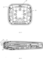
- the number of the electrodes 4 is at least two. In some embodiments of the present disclosure, the number of the electrodes 4 is four, but the number of the electrodes 4 is not limited herein.
- the four electrodes 4 are disposed on the cold compress member 1 in a matrix manner, and through the four electrodes 4, such that the biological parts may be fully beautified and the beauty effect may be improved via setting the four electrodes 4.
- the cold compress member 1 may be sapphire.
- the cold compress member 1 may be also a material with good thermal conductivity, such as a cold compress crystal, a cold compress glass, or the like.
- the sapphire is taken as example, but the material of the cold compress member 1 is not limited herein.
- the sapphire has a good heat transmission performance.
- the flake sapphire may conduct the heat generated by the one or more electrodes 4 on the biological parts fast to the refrigeration member 2, such that the temperature of the biological parts may be decreased rapidly to protect the skin health, thereby effectively preventing the skin from the damage.
- An installation relationship is between the each of the one or more electrodes 4 and the cold compress member 1.
- the each of the one or more electrodes 4 installed on the cold compress member 1 may be distributed in the center of the cold compress member 1, or may be distributed along a circumference.
- the one or more electrodes 4 and the cold compress member 1 contact with the biological parts. Since the one or more electrodes 4 are installed an entire piece of the sapphire, it is not necessary to install additional structures, such that there are no excess structures, such as a groove, a recess, a protrusion, an edge, or the like, to scratch the skin. Therefore, the one or more electrodes 4 are installed on the entire piece of the sapphire, which has comfort and heat transmission performances, thereby improving the comport of the contacted biological parts.
- an end surface of the each of the one or more electrodes 4 and the contact surface 11 of the cold compress member 1 may stably contact the skin at the same time. Therefore, the each of the one or more electrodes 4 is directly installed on the cold compress member 1, which has comfort and conduction performances.
- an area of the contact surface 11 of the cold compress member 1 is in a range from 350 square millimeters to 450 square millimeters, a thickness of the cold compress member 1 is in a range from 2mm to 5mm, and a ratio of the contact area to the thickness is in a range from 88:1 to 225:1.
- the area of the contact surface 11 of the cold compress member 1 may be 352 square millimeters, 440 square millimeters, or 450 square millimeters.
- the thickness of the cold compress member 1 may be 2mm, 4mm, or 5mm. In this way, the area of the contact surface 11 of the cold compress member 1 may be optimized, and the thickness of the cold compress member 1 may be optimized, thereby further cooling the cold compress member 1.
- a total power during discharge of the electrodes 4 is in a range from 3 watts to 10 watts.
- the dermal temperature of the biological parts is in a range from 60°C to 65°C
- the skin temperature is in a range from 40°C to 43°C.
- a specific heat capacity in a range from 40°C to 43°C of the sapphire is 0.8 joules per gram Celsius.
- the end surface of the each of the one or more electrodes 4 is located on the side of the contact surface 11 of the cold compress member 1, and is located within a closed circle defined by an outer boundary of the contact surface 11, which means that the heat generated by the biological parts due to the each of one or more electrodes 4 with a relatively small area of the end surface may be conducted radially to the surrounding area through the contact surface 11 with a relatively large area.
- the contact surface 11 may be designed to be small enough to save costs while ensuring the desired cooling effect without causing a large area of cold feeling.
- the temperature of the sapphire is lower than 20°C after the beauty device works for 30 seconds.
- the temperature of the sapphire is lower than 15°C after the beauty device works for 1 minute. Further, the temperature of the sapphire is lower than 10°C after the beauty device works for 1 minute and 30 seconds. It may be seen that the sapphire may play a good role in cooling the skin during continuous work.
- the beauty device may keep the epidermis in a comfortable temperature range continuously.
- the cold compress member 1 with a suitable size may better transmit heat.
- the cold compress member 1 may also ensure that the temperature of the biological parts may reach a balance when the beauty device is in operation, such that the temperature is not too high or too low. If the temperature is too high, the skin cells may be damage, resulting in a feeling of heat and pain. If the temperature is too low, the beauty effect cannot be achieved, resulting in a feeling of freezing.
- a ratio of an area of the contact surface 11 of the cold compress member 1 to the total area of a vertical projection of all the electrodes on a reference plane which the contact surface 11 of the cold compress member 1 is located on is in a range from 3.5:1 to 5:1.
- the ratio is 5:1
- the skin temperature may be maintained in a range from 38°C to 43°C, thereby providing more comfortable touch.
- the ratio is in the range from 3.5:1 to 5:1, it is possible to ensure that the one or more electrodes 4 and the cold compress member 1 may contact the biological parts fully, and the good conductivity of the cold compress member 1 may also be performed. In this way, the temperature of the biological parts in contact with a contact head 1 may be maintained in a range from 38°C to 43°C, and the epidermis of the biological part may be maintained in a comfortable temperature range continuously.
- an area ratio is not properly designed, it may directly lead to poor heat dissipation effect, thereby leading to thermal pain in the biological parts, the feel freezing in the biological parts due to a good heat dissipation, or uneven temperature that one part is hot and another part is cold at the same time.
- the refrigeration member 2 may be made of pato stone or crystal.
- the heat dissipation member 3 may be a ceramic base.
- the ceramic base has a good thermal conductivity, which may improve the heat dissipation effect of the heat dissipation member 3.
- an installation port 411 is defined on the fixing portion 41.
- a diameter of a projection of the installation port 411 on a plane which the cold compress member 1 is located on is smaller than that of a projection of the main body portion 42 on the plane which the cold compress 1 is located on.
- the main body portion 42 is at least partially exposed from the installation port 411. The main body portion 42 is effectively prevented from falling out by means of limiting the diameter of the installation opening 411, such that the main body portion 42 may be stably rolled on the fixing portion 41.
- sufficient rolling space may be provided for the main body portion 42 via the installation opening 411, such that the main body portion 42 may roll smoothly, thus the main body portion 42 better roll with the biological parts, thereby reducing the pulling of the biological part and improving the convenience of using the beauty device.
- the main body portion 42 may be a sphere or a ball.
- the sphere has an advantage of being easy to roll. At the same time, the touch of the sphere is soft. When the sphere is in contact with the biological parts, the scratch on the biological parts may be reduced by the sphere, such that the beauty of the skin by the main body portion 42 may be ensured, and at the same time, the safety may be improved as much as possible.
- the main body portion 42 is a conductor, that is, the main body portion 42 may discharge the biological parts, so as to achieve the effect of beautifying the biological part.
- the skin care assembly includes an elastic member 5.
- the elastic member 5 is arranged in the fixing portion 41 and located between the main body portion 42 and a bottom surface of the fixing portion 41. One end of the elastic member 5 abuts against the bottom surface of the fixing portion 41, and the other end of the elastic member 5 abuts against the main body portion 42, the main body portion 42 is pressed against the installation port 411 under an action of the elastic member 5.
- the main body portion 42 may be contacted with the biological parts softly in a rolling manner via the elastic member 5, such that the elastic member 5 abuts against the main body portion 42, thus the main body portion 42 may be contacted with the biological parts fully, thereby improving beauty effect.
- the main body portion 42 may be adjusted according to different biological parts during the process of contacting the biological parts, such that the main body portion 42 may roll better, thereby improving he convenience of using the beauty device.
- the elastic member 5 may be a spring or a soft silicone.
- the elastic member 5 is a spring, which is shown for illustration.
- the main body portion 42, the elastic member 5, and the fixing portion 41 are all conductors.
- the main body portion 42 is configured for beautifying the biological parts, and in the process of beautifying the biological parts, the elastic member 5 and the main body portion 42 are always kept in abutment state, which is beneficial to conduct the current among the main body portion 42, the elastic part 5, and the fixing portion 41, such that the main body portion 42 discharges the biological parts, such that the biological parts may be better beautified, thereby improving the beauty effect.
- the skin care assembly include a vibrating generator 6.
- the each of the one or more electrodes 4 vibrates at a certain frequency under an action of the vibrating generator 6.
- the vibrating generator 6 may be installed between the fixing portion 41 and the cold compress member 1.
- An output terminal of the vibrating generator 6 is connected to the fixing portion 41, and the each of the one or more electrodes 4 vibrates at the certain frequency under the action of the vibrating generator 6.
- the beauty device is in operation, the each of the one or more electrodes 4 may be maintained in a state of discharging the biological parts, and the each of the one or more electrodes 4 vibrates at the certain frequency so as to promote the blood circulation of the biological parts, thereby improving a state of the biological parts, activating the vitality, and enhancing the beauty effect.
- the skin care assembly includes the support 70 and the shell 20.
- the shell 20 is in a shape of long strip, and defines a cavity inside.
- the support 70 is configured to install an internal structure of the beauty device into the shell 20, that is, the internal structure of the beauty device may be assembled in the shell 20 so as to utilize the space inside the shell 20. In this way, the space utilization inside the shell 20 is greatly improved.
- the internal structure of the beauty device may be fixed in the shell 20 to form a whole beauty device.
- the support 70 is fixed with the shell 20 by snapping or screws.
- the support 70 is fixed with the shell 20 by snapping, which is shown for illustration.
- the support 70 is arranged with a first fastener 101.
- the shell 20 is arranged with a second fastener 201.
- the support 70 fixed with the shell 20 by snapping the first fastener 101 and the second fastener 201.
- the first fastener 101 may be a cantilever hook or a fixing hole. In some embodiments of the present disclosure, the first fastener 101 is the cantilever hook.
- the second fastener 201 may be also the cantilever hook or the fixing hole. In some embodiments of the present disclosure, the second fastener 201 is the fixing hole.
- the skin care assembly and the operation head of the skin care assembly are provided by some embodiments of the present disclosure.
- the cold compress member 1 includes the contact surface 11 and the conduction surface 12.
- the contact surface 11 is configured to contact the biological parts so as to cool and beautify the biological parts.
- the cooling side 21 of the refrigeration member 2 is thermally coupled with the conduction surface 12 of the cold compress member 1, thereby cooling the cold compress member 1.
- the heat dissipation member 3 is thermally coupled with the heat generating side 22 of the refrigeration member 2 to dissipate heat generated by the refrigeration member 2.
- the main body portion 42 is installed on the fixing portion 41 in the rolling manner.
- the fixing portion 41 is relatively fixed with the cold compress member 1 to fix the each of the one or more electrodes 4 on the refrigeration member 2.
- the each of the one or more electrodes 4 is contacted with the biological parts in a rolling manner via the main body portion 42, such that the friction between the each of the one or more electrodes 4 and the biological parts may be reduced, and the each of the one or more electrodes 4 may slide smoothly on the biological parts, thereby reducing a problem of pulling the skin or scratching the skin, and thus it is easy to use and simple to operate, which improves the convenience of using the beauty device during the use of the beauty device.
- a recess is defined on the fixing portion 41.
- the main body portion 42 is installed in the recess in a rolling manner and is not separated from the recess.
- An edge of the recess may be rounded to avoid cutting the skin.
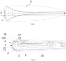
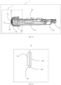
- FIG. 6 is an exploded schematic view in a direction of the skin care assembly according to an embodiment of the present disclosure.
- FIG. 7 is an exploded schematic view in another direction of the skin care assembly as shown in FIG. 6.
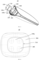
- FIG. 8 is a structural schematic view of the skin care assembly according to an embodiment of the present disclosure.
- FIG. 9 is a cross-sectional view of the skin care assembly along A-A direction shown in FIG. 8 .
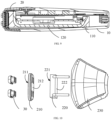
- FIG. 10 is an exploded schematic view of an operation head according to an embodiment of the present disclosure.
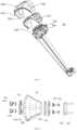
- FIG. 11 is a structural schematic view of a heat dissipation member and a heat pipe according to an embodiment of the present disclosure.
- FIG. 12 is a structural schematic view in a direction of the heat dissipation member as shown in FIG. 11 .
- a device body 10 of the beauty device 1 may be provided in some embodiments of the present disclosure.
- the device body 10 includes a heat dissipation member 110.
- the heat dissipation member 110 includes a thermal coupling surface 111.
- Thermal coupling surface 111 is configured to be thermally coupled with a heat generating surface 222 of an operation head 20 so as to dissipate heat generated by the operation head 20.
- the operation head 20 includes a contact surface 211 and the heat generating surface 222.
- the contact surface 211 is configured to contact and cool the skin.
- the heat dissipation member 110 extends from a head end of the device body 10 to a trailing end of the device body 10.
- the beauty device 1 includes the device body 10, the operation head 20, and a second shell 40.
- the operation head 20 is installed on the device body 10 via the second shell 40.
- FIG. 10 is an exploded schematic view of the operation head according to an embodiment of the present disclosure.
- the operation head 20 may include an electrode head 30.
- the beauty device 1 may discharge the skin via the electrode head 30, such that the skin may be beautified by the following method, such as the radio frequency, the micro-current, or the like.
- the temperature of the skin may be increased during the discharge process of the electrode head 30.
- the operation head 20 further includes a first shell 230 fixed relatively to the electrode head 30.
- the operation head 20 is dissipated heat via the heat dissipation member 110.
- the heat dissipation member 110 extends from the head end of the device body 10 to the trailing end of the device body 10, such that the heat dissipation member 110 may be enough long to increase a heat conduction path during heat dissipation. In this way, a longer heat conduction path may effectively prevent the heat from backtracking to the head end in a short time, thereby reducing the occurrence of heat backtracking.
- extending a heat dissipation path may improving the working efficiency of the operation head 20, which may meet the heat dissipation requirements in a case that rapid cooling is required. Reducing the heat backtracking may also prolong the cooling time of the contact surface 211 of the operating head 20. Further, the heating and cooling of the skin may be synchronized and balanced via the beauty device 1.
- the device body 10 of the beauty device 1 may be applied to the skin care assembly, and may be also applied to a non-contact-type beauty device.
- the contact surface 211 of the operation head 20 may contact and cool the skin.
- the heat on the skin may be transferred to the beauty device 1 through the contact surface 211. From a macroscopic point of view, a case that the heat is introduced into the beauty device 1 satisfies a general rule of transferring heat, that is, the heat is spontaneously transferred from an area with a high temperature to an area with a low temperature.
- the heat transfers from the skin, and then passes through the operation head 20, the heat dissipation member 110, and so on.
- a length of the heat dissipation member 110 is greater, the heat is transferred from the area with a high temperature to the area with a low temperature, such that the longer the conduction path needs to be passed, the more time it takes.
- the heat is generally transferred from the area with a high temperature to the area with a low temperature.
- the temperature of the device body 10 of the beauty device 1 or the parts of the beauty device 1 to which it is applied especially the temperature of the heat dissipation member 110 is substantially equal to or close to the temperature of the skin, a case of the heat backtracking may occur. That is, the heat accumulated on the heat dissipation member 110 cannot be dissipated, and the heat is reversely transferred to the operating head 20, such that the temperature of the skin cannot be reduced, or the efficiency of reducing temperature is low.
- the beauty device 1 cannot achieve the beauty effect, or may cause negative effects such as tingling on the skin.
- By setting a longer heat dissipation member 110 may slow down the time for the occurrence of heat retrospection to a certain degree, and prolong the working time of the beauty device 1.
- the heating and cooling of the skin by the beauty device 1 may reach a balanced state.
- the length of the heat dissipation member 110 cannot be increased indefinitely, and the length may be synthetically designed in conjunction with indicators and sizes of each part of the device body 10 of the beauty device 1.
- the heat dissipation member 110 extends from the head end of the device body 10 to the tail end of the device body 10.
- the heat dissipation member 110 is disposed on a trailing end of the device body 10, and a gap is defined between an ending of the heat dissipation member 110 and an ending of the trailing end of the device body 10.
- a size of the gap is less than one third of a length of the device body 10.
- the length of the heat dissipation member 110 cannot be increased indefinitely, and the length may be synthetically designed in conjunction with the indicators and sizes of the each part of the device body 10 of the beauty device 1.
- a relationship between the length of the heat dissipation member 110 and the length of the device body 10 is provided by some embodiments of the present disclosure. Specifically, the heat dissipation member 110 is disposed on the trailing end of the device body 10, and the gap is defined between the ending of the heat dissipation member 110 and the ending of the trailing end of the device body 10. The size of the gap is less than one third of the length of the device body 10.
- a gravity center of the device body 10 may be close to the operation head 20.
- the gravity center of the device body 10 may be in the middle of the device body 10, or may be close to the ending of the trailing end of the device body 10.
- a weight configuration of the device body 10 can be set as required.
- the applicant has found that when the length of the heat dissipation member 110 is no more than that of the device body 10, and the gravity center of the heat dissipation member 110 is arranged close to the head, such that the user may grip more stably and comfortably during the use of the beauty device 1.
- the gap is defined between the ending of the heat dissipation member 110 and the ending of the trailing end of the device body 10, such that a part of the space may be reserved for installing components that need to be installed on the trailing end of the device body 10, such as a charging port 140 and the like.
- a size of the gap may be less than one third of the device body 10. At this time, it cannot only meet the needs of the cooling time of the beauty device 1, but also facilitate the user to grasp and use the beauty device 1, and thus it is also possible to facilitate to fix some components, which serves three birds with one stone.
- the length of the heat dissipation member 110 is longer than that of the device body 10, such that the heat dissipation member 110 is exposed from the device body 10 or corresponding beauty device 1.
- the trailing end of the heat dissipation member 110 is directly exposed from the device body 10, which may be also possible to increase the heat dissipation efficiency and prolong the cooling time of the device body 10 or the beauty device 1.
- an exposed part of the heat dissipation member 110 may be used with other components or devices so as to achieve some certain effects.
- the exposed part of the heat dissipation member 110 may be used in conjunction with a cooling device, thereby further prolonging the cooling time or pre-cooling the heat dissipation member 110, which is convenient for customers to use.
- the exposed part of the heat dissipation member 110 may be matched with a specific fixing mount so as to facilitate the placement of the beauty device 1. Compared with maintaining stability through the shell of the device body 10 when placed, the heat dissipation member 110 penetrates almost the entire beauty device 1, which is more convenient for maintaining stability. Other combinations and effects that may be obtained by simple derivation are all within the scope of the present disclosure, and will not be repeated here.
- an air outlet 150 is defined on the trailing end of the device body 10, and the trailing end of the heat dissipation member 110 is arranged corresponding to the air outlet 150.
- the air outlet 150 is defined on the trailing end of the device body 10 so as to facilitate the device body 10 to dissipate heat.
- the trailing end of the heat dissipation member 110 is arranged corresponding to the air outlet 150, which may facilitate the heat conducted to the tail of the heat dissipation member 110 to dissipate from the air outlet 150.
- the heat in the device body 10 needs to dissipate into the air eventually to complete the heat dissipation.
- the air outlet 150 communicates the air inside and outside the device body 10, and cooperates with the heat dissipation member 110 extending to the trailing end, thereby effectively dissipating heat to the device main body 10.
- thermal coupling surface 111 is disposed on an end surface 112 of the head end of the heat dissipation member 110.
- a recess 113 is defined on the end surface 112.
- a bottom surface of the recess 113 is thermal coupling surface 111.
- the operation head 20 includes a cold compress member 210 and a refrigeration member 220.
- the cold compress member 210 includes a contact surface 211 and a conduction surface 212.
- a cooling side 221 of the refrigeration member 220 is thermally coupled with the conduction surface 212 of the cold compress member 210, so as to cool the cold compress member 210.
- a heat generating side of the refrigeration member 220 is a heat generating surface 222.
- the heat generating surface 222 is thermally coupled with the heat dissipation member 110, so as to dissipate heat generated by the refrigeration member 220.
- the refrigeration member 220 is disposed in the recess 113, and the cooling side 221 is higher than the recess 113.
- Thermal coupling surface 111 is disposed on the end surface 112 of the head end of the heat dissipation member 110, and is thermally coupled with the heat generating surface 222 of the operation head 20, so as to dissipate the heat generated by the operation head 20.
- the recess 113 is disposed on the end surface 112, such that it is convenient to place and fix the refrigeration member 220, thereby improving the stability of the device body 10.
- a position of the refrigeration member 220 in a plane direction which the end surface 112 is located on may be limited by the recess 113, such that a position of the refrigeration member 220 is fixed in the plane direction.
- the refrigeration member 220 includes a cooling side 221 and a heat generating side.
- the cooling side 221 is configured to cool the cold compress member 210 and the like.
- the heat generating side generates heat due to the operation of the refrigeration member 220, and the heat is not beneficial to the operation of the device body 10 or the beauty device 1. In this case, it is necessary to arrange the heat dissipation member 110 to dissipate the heat of the heat generating side.
- the heat generating surface 222 of the operating head 20 is the heat generating side of the refrigeration member 220, and is thermally coupled with thermal coupling surface 111 of the refrigeration member 110.
- the cooling side 221 and the heat generating side are two sides of the refrigeration member 220.
- the heat dissipation member 110 dissipates the heat of the refrigeration member 220.
- the heat of the heat generating side of the refrigeration member 220 may be conducted toe the heat dissipation member 110, such that the temperature of an area close to the refrigeration member 220 is higher than that of the cooling side 221 of the refrigeration member 220.
- heat always flows spontaneously from an area with a high temperature to an area with a low temperature. Therefore, when the heat dissipation member 110 contacts the cooling side 221 of the refrigeration member 220, the heat that should be conducted out may be re-transferred to the cooling side 221 of the refrigeration member 220, resulting in backtracking of the heat, thereby affecting the cooling effect.
- the cooling side 221 is higher than the recess 113, thereby preventing the cooling side 221 from contacting the heat dissipation member 110, and thus it is possible to reduce the heat backtracking and prolong the cooling time of the beauty device 1.
- the cooling time of the beauty instrument 1 is prolonged in a structural manner, such that it is possible to reduce the cooling burden of the refrigeration member 220 and reduce the related material and design costs. At the same time, it is also possible to improve the working efficiency of the refrigeration member 220, which may meet the heat dissipation requirements of the refrigeration member 220 in a case that rapid cooling is required.
- the heat generating side of the refrigeration member 220 may be a plane, and thermal coupling surface 111 may be also a plane.
- the heat generating side of the refrigeration member 220 is thermally coupled with thermal coupling surface 111 of the heat dissipation member 110, such that the heat generating side contacts thermal coupling surface 111 to transfer the heat.
- materials such as thermally conductive silicone grease or the like may be filled between the refrigeration member 220 and the heat dissipation member 110 so as to transfer the heat.
- the heat generating side of the refrigeration member 220 may directly or indirectly contact with thermal coupling surface 111, for example, a thermal conductive medium such as thermal conductive silicone grease is filled between the heat generating side of the refrigeration member 220 and thermal coupling surface 111.
- FIG. 11 is a structural schematic view of a heat dissipation member and a heat pipe according to another embodiment of the present disclosure.
- a ratio of a thickness of the refrigeration member 220 to a depth of the recess 113 is in a range from 2 to 10.
- a unit of thickness of the refrigeration member 220 is millimeters, and a unit of depth of the recess 113 is millimeters.
- the heat generating side of the refrigeration member 220 is thermally coupled with thermal coupling surface 111.
- the refrigeration member 220 is disposed in the recess 113, so as to limit a position of the refrigeration member 220 on the same plane as thermal coupling surface 111.
- the refrigeration member 220 may be relatively fixed with the heat dissipation member 110 without sliding, such that it is helpful for the stability of the structure of the beauty device 1, and the stable structure is helpful for dissipating heat.
- Two objects in contact with each other do not change their positions, and the heat is transferred smoothly and continuously from the area with high temperature to the area with low temperature. In this way, the efficiency of transferring heat is high and stable.
- the ratio of the thickness of the refrigeration member 220 to the depth of the recess 113 is in a range from 2 to 10, which may not only meet the requirements of structural stability, but also ensure a good performance of the transferring heat, and it is further possible to prevent the heat from backtracking to the cooling side 221.
- the ratio of the thickness of the refrigeration member 220 to the depth of the recess 113 is in a range from 2 to 10, which may adapt to a size of the handheld beauty device, and the refrigeration member 220 in this ratio is stably disposed on the heat dissipation member 110.
- an installation method of the refrigeration member 220 is to be pressed into the recess 113 by a certain pressure, so as to save the cost of processing the refrigeration member 220 and corresponding installation structures.
- the ratio of the thickness of the cooling element 220 to the depth of the recess 113 is in a range from 2 to 10, such that the refrigeration member 220 is not easily to move relative to each other when the refrigeration member 220 is pressed into the recess 113. Even if the beauty device 1 falls off the ground or collides in daily use, the structure of the beauty device 1 may be kept stable. The refrigeration member 220 cannot pop out of the recess 113 and be stuck on an edge of the recess 113 due to the deformation caused by such a degree of collision. Therefore, the beauty device 1 has a better durability in the daily use.
- a section of a heat pipe 120 is bent to form a bending portion 121, the bending portion 121 abuts against an end of the heat dissipation member 110 close to the operation head 20.
- the heat pipe 120 has a hollow and sealing structure and is filled with liquid, and the liquid is not full of the heat pipe 120.
- the heat pipe 120 is configured to accelerate the heat dissipation from the head end to the trailing end of the heat dissipation member 110.
- the section of the heat pipe 120 is bent to form the bending portion 121, the bending portion 121 abuts against the end of the heat dissipation member 110 close to the operation head 20, such that it is possible to increase an area of the heat pipe 120 close to the operation head 20, thereby improving the heat dissipation efficiency.
- the heat is transferred from the operating head 20 to the heat dissipation member 110, and then transferred from the heat dissipation member 110 to the bending portion 121 of the heat tube 120. Therefore, there is also thermal coupling between the operation head 20 and the bending portion 121, and the bending portion 121 may improve the heat dissipation efficiency relative to the straight pipe or the like.
- an avoidance groove 114 is defined on the heat dissipation member 110, the heat pipe 120 is arranged along an inner wall of the avoidance groove 114 and welded to the inner wall of the avoidance groove 114, and an end of the heat pipe 120 away from the bending portion 121 extends to the end of the heat dissipation member 110.
- the heat pipe 120 is disposed in the avoidance groove 114, and arranged along the inner wall of the avoidance groove 114, thereby increasing the contact surface 211 between the heat pipe 120 and the heat dissipation member 110. In this way, the heat pipe 120 may effectively conduct heat conduction to the heat dissipation member 110, thereby effectively helping the heat dissipation member 110 to quickly transfer the heat of the operation head 20 to the trailing end of the beauty device 1.
- FIG. 13 is an exploded schematic view in another direction of a beauty device according to an embodiment of the present disclosure.
- the device body 10 further includes an installation plate 130 and the charging port 140.
- the installation plate 130 is installed on the opening of the recess 113 and extends towards the trailing end of the device body 10.
- the charging port 140 is disposed on an end of the installation plate 130 and exposed from the device body 10.
- the installation plate 130 is configured to install necessary components or elements of the beauty device 1, such as a circuit board, a battery, and so on.
- the beauty device 1 may be used by plugging in or by charging. When he beauty device 1 is used by charging, the battery is charged by the beauty device 1 by means of the charging port 140 being connected with an external power cord. When used by plugging, the beauty device 1 is used by means of the charging port 140 being connected with the external power cord.
- the charging port 140 When the beauty device 1 is used by plugging, a certain impedance may be generated by the charging port 140 due to the case that internal points of the charging port 140 contact, such that the heat may be generated when the current passes. Therefore, the charging port 140 is disposed on an ending of the installation plate 130 and away from the heat dissipation member 110, such that it is possible to prevent the heat generated by the charging port 140 from being traced back to the device body 10 and even the operation head 20, which may affect the cooling effect, thereby affecting the beauty effect.
- the heat dissipation member 110 is integrally formed.
- the heat dissipation member 110 may be processed by an entire piece of aluminum, so as to obtain a structure required for partial installation, supporting and keeping space.
- the integrally formed heat dissipation member 110 has better integrity, and each structure is more coherent, which is conducive to dissipate heat. When heat flows through one object and two objects in contact with each other, the heat conduction efficiency of the former is better than that of the latter.
- the beauty device body further includes a third shell 160 and an appearance member 170.
- the heat dissipation member 110 and the charging port 140 are installed and received in the third shell 160.
- the number of the appearance members 170 may be two, and the two appearance members 170 are disposed outside of the third shell 160.
- the appearance member 170 may be an elastic, high damping material such as silicone, sponge, or the like. The appearance member 170 made of the elastic and the high damping material may provide a more comfortable and secure grip for the user.
- the skin care assembly may also be provided in some embodiments of the present disclosure.
- the skin care assembly includes the above-mentioned device body 10 of the beauty device.
- the beauty device further includes the operation head 20.
- the operation head 20 includes the contact surface 211 and the heat generating surface 222.
- the contact surface 211 is configured to contact and cool the skin.
- the operation head 20 is disposed on the head end of the skin care assembly.
- the following technical effects of the device body of the beauty device may be achieved.
- heat of the operation head 20 is dissipated via the heat dissipation member 110.
- the heat dissipation member 110 extends from the head end of the device body 10 to the trailing end of the device body 10, such that the heat dissipation member 110 may be enough long to increase a heat conduction path during heat dissipation. In this way, a longer heat conduction path may effectively prevent the heat from backtracking to the head end in a short time, thereby prolonging the cooling time of the contact surface 211 of the operating head 20.
- the heat dissipation member 110 is disposed on the trailing end of the device body 10, and the gap is defined between the ending of the ending of the heat dissipation member 110 and the ending of the trailing end of the device body 10.
- a size of the gap is less than one third of a length of the device body 10. In this way, the heat dissipation member 110 may not only meet needs of heat dissipation, but also make the center of gravity of the beauty device 1 meet the needs of use.
- the skin care assembly may also be provided in some embodiments of the present disclosure.
- the skin care assembly includes the above-mentioned device body 10 of the beauty device 1.
- the beauty device 1 further includes the operation head 20.
- the operation head 20 includes the contact surface 211 and the heat generating surface 222.
- the contact surface 211 is configured to contact and cool the skin.
- the operation head 20 is disposed on the head end of the skin care assembly.
- the sapphire may be either artificial or natural.
- the skin care assembly may also be provided in some embodiments of the present disclosure.
- the skin care assembly includes the above-mentioned device body of the beauty device.
- the beauty device further includes the operation head.
- the operation head includes a contact surface and a heat generating surface. The contact surface is configured to contact and cool the skin.
- the operation head is disposed on the head end of the skin care assembly.
- FIG. 14 is a perspective exploded schematic view of the skin care assembly according to an embodiment of the present disclosure.
- FIG. 15 is a perspective exploded schematic view of the skin care assembly according to another embodiment of the present disclosure.
- the skin care assembly 10 includes a cold compress member 100, a refrigeration member 200, a heat dissipation member 300, one or more electrode heads 400, and a first cover 500.
- the cold compress member 100 includes a contact surface 100a and a conduction surface 100b.
- the contact surface 100a is configured to contact the skin.
- the cooling side 210 of the refrigeration member 200 is thermally coupled with the conduction surface 100b of the cold compress member 100, thereby cooling the cold compress member 100.
- the heat dissipation member 300 is thermally coupled with the heat generating side 220 of the refrigeration member 200 to dissipate heat generated by the refrigeration member 200.
- the each of the one or more electrode heads 400 is relatively fixed with the cold compress member 100, and is configured to discharge and heat the contacted skin.
- the first cover 500 is configured to fix the cold compress member 100 and the refrigeration member 200 to the heat dissipation member 300.
- the cold compress member 100 and the one or more electrode heads 400 may be combined with other parts of the skin care assembly 10 via the first cover 500, thereby forming a complete skin care assembly. In this way, the cold compress member 100 and the refrigeration member 200 are fixed to the heat dissipation member 300 via the first cover body 500, which is also more convenient during assembly and installation.
- the one or more electrodes 4 are discharged, for example, to generate the radio frequency or the micro-current.
- the current passes through and stimulates the skin, such that the desired beauty effect may be achieved. Since the skin is equivalent to the electrical resistance, a temperature of the skin may increase.
- the cold compress member 100, the refrigeration member 200, and the heat dissipation member 300 are thermally coupled with each other, such that the heat generated by the skin may be conducted from the cold compress member 100to the heat dissipation member 300 via the refrigeration member 200, thereby dissipating the heat from the skin care assembly.
- the cold compress member 100 is relatively fixed with the each of the one or more electrode heads 400.
- the refrigeration member 200 is disposed between the heat dissipation member 300 and the cold compress member 100 to form a sandwich structure of the heat dissipation member 300, the refrigeration member 200, and the cold compress member 100.
- the first cover 500 is configured to fix the cold compress member 100 and the refrigeration member 200 in the heat dissipation member 300.
- the cold compress member 100 and the one or more electrode heads 400 contacted the skin, and the cold compress member 100 is adjacent to the each of the one or more electrode heads 400.
- the cold compress member 100 may provide a lower temperature environment via the refrigeration member 200, such that the skin located shallower is cooled by the cold compress member 100 in time, thereby improving touch for the biological parts.
- the cold compress member 100 and the refrigeration member 200 are fixed in the heat dissipation member 300 via the first cover 500, such that it is possible to facilitate the assembly and installation of the skin care assembly.
- the cold compress member 100 or the cooling element 200 in the skin care assembly needs to be replaced, it is only necessary to take out the first cover 500 from the heat dissipation member 300, and the cold compress element 100 and the cooling element 200 may be removed from the skin care assembly and replaced.
- the cold compress element 100 and the refrigeration member 200 are sequentially fixed on the heat dissipation member 300 via the first cover 500, which is simple and convenient.
- a muscle contraction movement is caused when the current passes through the skin, thereby achieving the beauty effect.
- the skin temperature and the dermal temperature increase.
- the skin temperature is increased due to heat generated by skin cells and heat converted from electrical energy.
- the heat generated by the one or more electrode heads 400 stimulating the epidermis is reduced via the cold compress member 100, thereby cooling the skin epidermis, and achieving a cold compress and cooling function.
- the cold compress member 100 is cooled by the refrigeration member 200, such that the skin epidermis may be continuously cooled by the cold compress member 100.
- it is also possible to expand contract the skin such that the skin's breathing is enhanced, thereby protecting the skin from damage and better stimulating the tightening and regeneration of dermal collagen, tightening the skin, and improving beauty effect.
- the skin may be facial skin, arm skin, or the like.
- the skin located shallower may be the epidermis, and the skin located deeper may be the dermis.
- the discharge may generate the radio frequency, the microcurrent, or the like, so as to beautify the skin.
- the heat generated on the skin by the one or more electrode heads 400 is conducted to the cold compress member 100, and the skin is contacted with the contact surface 100a of the cold compress member 100, such that the epidermis is cooled by the cold compress member 100.
- the conduction surface 100b of the cold compress member 100 is thermally coupled with the cooling side 210 of the refrigeration member 200, such that the cold compress member 100 is cooled by the refrigeration member 200 to absorb the heat conducted by the cold compress member 100.
- the heat may be generated on the heat generating side 220 accordingly, and the heat generating side 220 of the refrigeration member 200 is thermally coupled with the heat dissipation member 300, such that the heat generated by the refrigeration member 200 is conducted to the heat dissipation member 300 and passes through the heat dissipation member 300, and thus the heat may be exhausted from the skin care assembly via the heat dissipation member 300.
- the return of heat is reduced in a short duration, thereby prolonging the time that the skin care assembly maintains a state of the temperature balance.
- thermal coupling between the cooling side 210 of the refrigeration member 200 and the conduction surface 100b of the cold compress member 100, and thermal coupling between the heat dissipation member 300 and the heat generating side 220 of the refrigeration member 200 may be realized by means of heat transmission, thermal convection, thermal radiation, or any combination of the above-mentioned three methods.
- an opening 510 is defined on the first cover 500.
- the opening 510 of the first cover 500 is arranged corresponding to the cold compress member 100.
- a size of the opening 510 in at least one radial direction is smaller than a size of the cold compress member 100 in the radial direction.
- An edge of the cold compress member 100 is pressed to the heat dissipation member 300 through an edge of the opening 510, such that the cold compress member 100 and the refrigeration member 200 are fixed on the heat dissipation member 300.
- a plane size of the contact surface 100a of the cold compress member 100 is substantially equal to that of the opening 510.
- a plane size of the conduction surface 100b of the cold compress member 100 is greater than that of the opening 510.
- an edge of the conduction surface 100b of the cold compress member 100 may be pressed towards the heat dissipation member 300 in an axial direction by the edge of the opening 510, such that the cold compress member 100 and the refrigeration member 200 are fixed in the heat dissipation member 300.
- the cold compress member 100 and the refrigeration member 200 have specific functions, and the manufacturing and processing processes are generally complicated. Therefore, the opening 510 is defined on the first cover 500, such that the cold compress member 100 and the refrigeration member 200 are fixed in the heat dissipation member 300 with a simple structure, thereby saving the internal space of the skin care component 10, reducing the production difficulty, and decreasing the production cost.
- FIG. 16 is a front structural schematic view of the skin care assembly according to another embodiment of the present disclosure.
- each of the one or more electrode heads 400 is disposed on the edge of the opening of the first cover 500.
- the number of the electrode heads 400 is at least two.
- the at least two electrode heads 400 are arranged on an outer periphery of the contact surface 100a of the cold compress member 100 and spaced apart from each other.
- each of the one or more electrode heads 400 includes an end portion 410 and an installation post 420.
- An installation hole 100c is defined on the contact surface 100a of the cold compress member 100.
- the installation hole 100c is inserted through the entire cold compress member 100.
- a size of the installation hole 100c is set correspondingly to the installation post 420.
- the installation post 420 is inserted through the installation hole 100c, such that the one or more electrode heads 400 are installed on the cold compress member 100.
- the installation post 420 may be fixed relatively to the cold compress member 100 via an end of the installation post 420 close to the conduction surface 100b.
- the end of the installation post 420 close to the conduction surface 100b is arranged with threads, and screw caps may be used to fix the one or more electrode heads 400 to the cold compress member 100.
- the one or more electrode heads 400 may also be kept relatively fixed to the cold compress member 100 by other means.
- the installation post 420 is inserted through the cold compress member 100, and the end portion 410 is installed on a surface of the contact surface 100a of the cold compress member 100.
- the heat generated by the end portion 410 from the skin may be conducted radially to the surrounding via the contact surface 100a of the cold compress member 100 disposed around the end portion 410.
- the contact surface 11 of the cold compress member 100 may be designed to be small enough to save costs while ensuring the desired cooling effect without causing the large area of cold feeling at the parts in contact with the skin.
- An installation relationship is between the each of the one or more electrode heads 400 and the cold compress member 100.
- the each of the one or more electrode heads 400 installed on the cold compress member 100 may be distributed in the center of the cold compress member 100, or may be distributed along a circumference.
- the end portion 410 of the each of the one or more electrode heads 400 and the contact surface 100a of the cold compress member 100 contact with the skin. Since the one or more electrode heads 400 are installed an entire piece of the cold compress member 100, it is not necessary to install additional structures, such that there are no excess structures, such as a groove, a recess, a protrusion, an edge, or the like, to scratch the skin.
- the one or more electrode heads 400 are installed on the entire piece of the cold compress member 100, which has comfort and heat transmission performances, thereby improving the comport of the parts in contact with the skin.
- end portion 410 of the each of the one or more electrode heads 400 and the contact surface 100a of the cold compress member 100 may stably contact the skin at the same time. Therefore, the each of the one or more electrode heads 400 is directly installed on the cold compress member 100, such that the skin care assembly 10 has a comfort and conduction performances.
- the skin care assembly 10 includes at least two electrode heads 400.
- the at least two electrode heads 400 are arranged on an outer periphery of the cold compress member 100 and spaced apart from each other.
- at least one electrode head 400 is a negative electrode
- at least one electrode head 400 is a positive electrode.
- the electrode heads 400 may be distributed on the cold compress member 100 in a point shape, or may be distributed on the cold compress member 100 in a line shape. The distribution of the electrode heads 400 cannot be too dense, and the spacing distribution makes the end portion 410 of each electrode head 400 contact with the skin, and the cold compress member 100 may also fully contact with the skin.
- one or more electrode heads 400 may be disposed on the cold compress member 100.
- the one or more electrode heads 400 are distributed along a circumference direction of a polygon and spaced apart from each other.
- the cold compress member 100 is a square with arc chamfers
- the four electrode heads 400 are respectively distributed at the four arc chamfers.
- the one or more electrode heads 400 may be distributed in a radial shape (such as a flower shape or a star shape) as a whole on the polygon.
- the one or more electrode heads 400 may also be distributed in a line shape or a plurality of line shapes on the polygon.
- FIG. 17 is a cross-sectional structural schematic view of the skin care assembly according to another embodiment of the present disclosure.
- a first fastener 520 is fixed on the first cover 500.
- a second fastener 310 is fixed on the heat dissipation member 300 and snap-connected to the first fastener 520, such that the cold compress member 100 and the refrigeration member 200 are fixed on the heat dissipation member 300 via the first cover 500.
- the fist cover 500 is a square cover including four side surfaces, and the first fastener 520 may be fixed on at least one side surface.
- the heat dissipation member 300 is also a square structure, and the second fastener 310 is disposed correspondingly to the first fastener 520 on a side surface of the heat dissipation member 300. The first fastener 520 is fastened into the second fastener 310, such that the fist cover 500 may be fixed with the heat dissipation member 300.
- each of a first side surface 530 and a second side surface 540 of the fist cover 500 is arranged with the first fastener 520.
- Each of a corresponding third side surface 320 and a corresponding fourth side surface 330 of the heat dissipation member 300 is correspondingly arranged with the second fastener 310.
- the heat generating side 220 of the refrigeration member 200 is thermally coupled with the heat dissipation member 300.
- the cooling side 210 of the refrigeration member 200 is thermally coupled with the conduction surface 100b of the cold compress member 100.
- the plane size of the contact surface 100a of the cold compress member 100 is substantially equal to that of the opening 510.
- the fist cover 500 is sleeved on the contact surface 100a via the opening 510, and the first fastener 520 is fastened into the second fastener 310, such that the first fastener 520 is locked by the second fastener 310 and the first cover 500 is pulled, thereby providing a force along an axial direction of the skin care assembly 10.
- the first cover 500 is fixed on the heat dissipation member 300, such that the cold compress member 100 and the refrigeration member 200 are fixed on the heat dissipation member 300 via the first cover 500.
- the first fastener 520 may be the cantilever hook.
- the second fastener 201 may be the fixing hole. By setting the cantilever hook and the fixing hole, the fixing hole is locked by the cantilever hook, such that the fist cover 500 is fixed on the heat dissipation member 300.
- FIG. 18 is a perspective exploded structural schematic view of the skin care assembly according to some embodiments of the present disclosure viewed from a view angle.
- FIG. 19 is a perspective exploded structural schematic view of the skin care assembly according to some embodiments of the present disclosure viewed from another view angle.
- the heat dissipation member 300 includes a thermal coupling surface 340, and thermal coupling surface 340 is thermally coupled with the heat generating side 220 of the refrigeration member 200.
- Two sides of thermal coupling surface 340 are respectively connected with the third side surface 320 and the fourth side surface 330.
- a part of the second fastener 310 is disposed a side of thermal coupling surface 340 of the heat dissipation member 300 and snap-connected to the first fastener 520.
- a remaining part of the second fastener 320 extends towards the third side surface 320 and the fourth side surface 330 of the two sides of thermal coupling surface 340.
- a first guidance portion 350 and a second guidance portion 360 are arranged on an outside of the second fastener 310 and are configured to guide the first fastener 520 disposed on each of the first side surface 530 and the second surface 540 of the first fastener 520 to fasten into the second fastener 310.
- the first side surface 530 and the second surface 540 of the first fastener 520 are arranged with a first lateral wing 550 and a second lateral wing 560.
- the first lateral wing 550 and the second lateral wing 560 are corresponding to the third side surface 320 and the fourth side surface 330 of the heat dissipation member 300.
- the first lateral wing 550 and the second lateral wing 560 of the first cover 500 are assembled with the heat dissipation member 300 via the first guidance portion 350 and the second guidance portion 360.
- the third side surface 320 and/or the fourth side surface 330 connected to thermal coupling surface 340 may be arranged with one or more second fasteners 310, which is not limited herein.
- the first side surface 530 and the second surface 540 of the first fastener 520 are correspondingly arranged with the same number of the first fasteners 520.
- the first lateral wing 550 and the second lateral wing 560 of the first cover 500 are configured to guide the first fastener 520 fasten into the second fastener 310 via the first guidance portion 350 and the second guidance portion 360 correspondingly, such that it is more convenient to install and align when the skin care assembly 10 is assembled with the first cover 500 and the heat dissipation member 300.
- the first lateral wing 550 and/or the second lateral wing 560 of the first cover 500 are arranged with one of a guidance groove 370 and a guidance rib 570.
- One of the guidance groove 370 and the guidance rib 570 extends towards the third side surface 320 and/or the fourth side surface 330 of the heat dissipation member 300 along the first side surface 530 and/or the second surface 540 of the first cover 500.
- the third side surface 320 and/or the fourth side surface 330 of the heat dissipation member 300 are arranged with one of the guidance groove 370 and the guidance rib 570.
- the guidance rib 570 is assembled with the guidance groove 370 in a sliding manner, such that the guide of the guidance groove 370 or the guidance rib 570 disposed on the first lateral wing 550 and/or the second lateral wing 560 of the first cover 500 are guided by the corresponding guidance groove 370 or the guidance rib 570 of the first guidance portion 350 and the second guidance portion 360, thereby fastening the second fastener 310 into the first fastener 520.
- one of the two lateral wings of the first cover 500 and the corresponding one of the two side surfaces of the heat dissipation member 300 are smooth.
- the other one of the two lateral wings of the first cover 500 and the corresponding other one of the two side surfaces of the heat dissipation member 300 are arranged with the guidance groove 370 and the guidance rib 570 respectively.
- the first side surface 530 and the second surface 540 of the first cover 500, and the third side surface 320 and the fourth side surface 330 of the heat dissipation member 300 may be clearly distinguished, thereby playing a foolproof role.
- the second lateral wing 560 of the second surface 540 of the first cover 500 is arranged with the guidance rib 570.
- the first lateral wing 550 of the first surface 530 is a smooth surface.
- the second guide portion 360 of the fourth side 330 of the of the heat dissipation member 300 is correspondingly arranged with the guidance groove 370.
- the first guidance portion 350 of the third side surface 320 is a smooth surface.
- first side surface 530 and the third side surface 320 are correspondingly arranged, such that the first fastener 520 of the first cover 500 may be smoothly fastened into the second fastener 310 of the heat dissipation member 300 via a cooperation of the guidance rib 570 and the guidance groove 370, thereby improving the convenience of the installation and use of the skin care assembly 10.
- FIG. 20 is a partial exploded structural schematic view of the skin care assembly according to an embodiment of the present disclosure.
- the cold compress member 100 includes a cold compress sheet 110a and a cold-guiding sheet 110.
- the cold-guiding sheet 120 is disposed between the cold compress sheet 110a and the refrigeration member 200.
- the contact surface 100a is disposed a side of the cold compress sheet 110a away from the refrigeration member 200.
- the conduction surface 100b is disposed a side of the cold-guiding sheet 120 away from the cold compress sheet 110a.
- a size of the cold-guiding sheet 120 in at least one radial direction is greater than a size of the opening 510 of the first cover 500 in the radial direction, such that an edge of the cold-guiding sheet 120 is pressed to the heat dissipation member 300 by an edge of the opening 510 of the first cover 500.
- the cold compress sheet 110a is disposed in one of an inner side and an outside of the opening 510, and the cold-guiding sheet 120 is disposed in the other of the inner side and the outside of the opening 510.
- a fixing hole 421 is defined on the installation post 420 of the electrode head 400 in an axial direction.
- the installation post 420 is inserted into the cold compress sheet 110a and the installation hole 100c of the cold-guiding sheet 120, and the installation post 420 is fixed by a fixing member 422.
- the electrode head 400 may be installed on the cold compress member 100, and the cold compress sheet 110a and the cold-guiding sheet 120 are fixed on the inner side and the outside of the openings 510.
- the fixing hole 421 may be a threaded hole, and the fixing member 422 may be a screw.
- a size of the cold-guiding sheet 120 in a radial direction is greater than a size of the opening 510 of the first cover 500 in the radial direction, such that when the skin care assembly 10 is assembled, an edge of the cold-guiding sheet 120 is pressed to the heat dissipation member 300 by an edge of the opening 510 of the first cover 500, thus the cold compress member 100 and the refrigeration member 200 are fixed in the heat dissipation member 300.
- FIG. 21 is a partial exploded structural schematic view of a connection member of the skin care assembly according to another embodiment of the present disclosure.
- a connection member 423 is arranged between the cold-guiding sheet 120 and the fixing member 422, and is configured to fix the cold compress member 100 and the refrigeration member 200.
- the connection member 423 includes a main body portion 4231 and an extending portion 4232.
- a through hole 423a is defined on the main body portion 4231.
- the main body portion 4231 is inserted into the through hole 423a and the installation hole 100c via the fixing member 422, such that the connection member 423 is fixed to the cold compress member 100.
- the extending portion 4232 is arranged with two right-angled sides substantially perpendicular with each other.
- the fixing hole 421 is defined on each of two side edges corresponding to the two right-angled sides, and the two side edges are connected to each other and substantially perpendicular with each other.
- the extending portion 4232 is inserted into the fixing hole 421 via the fixing member 422, such that the cold compress member 100 is fixed to the refrigeration member 200.
- the cold compress sheet 110a of the cold compress member 100 is contacted with the cooling side 210 of the refrigeration member 200 by the method of direct surface contact.
- the cold compress member 100 is contacted with the cooling side 210 by the method of indirect surface contact via the conduction surface 100b of the cold-guiding sheet 120. Therefore, by the method of the surface contact, the heat conduction is more sufficient, and the conduction effect may be maximized.
- the cold-guiding sheet 120 may be aluminum nitride ceramics or other materials with good thermal conductivity.
- the heat transmission effect may be maximized by the method of the surface contact.
- the electrode heads 400, the cold compress sheet 110a, and the cold-guiding sheet 120 are made of materials with good heat transmission performance. However, when the electrode heads 400, the cold compress sheet 110a, and the cold-guiding sheet 120 are contacted with each other, gaps may be defined between the electrode heads 400, the cold compress sheet 110a, and the cold-guiding sheet 120.
- a first sealing ring 130 is disposed between a gap defined between the electrode head 400 and the cold compress sheet 110a
- a second sealing ring 140 is disposed between a gap defined between the cold compress sheet 110a and the cold-guiding sheet 120, thereby filling the gaps between electrode head 400, the cold compress sheet 110a, and the cold-guiding sheet 120.
- thermal grease may be filled in the gaps, which may make the heat transfer more sufficient, and also make the temperature control more smoothly, thereby improving the comfort of the skin feeling.
- the cold compress sheet 110a is disposed in the opening 510, and the cold compress sheet 110a has a first radial dimension and a second radial dimension different from the first radial dimension at different thickness positions.
- the opening has a third radial dimension and a fourth radial dimension different from the third radial dimension at different depth positions.
- a part of the cold compress sheet 110a having the first radial dimension is closer to the cold-guiding sheet 120 than a part of the cold compress sheet 110a having the second radial dimension.
- a part of the opening 510 having the third radial dimension is closer to the cold-guiding sheet 120 than a part of the opening 510 having the fourth radial dimension.
- the first radial dimension is smaller than the third radial dimension
- the second radial dimension is smaller than the fourth radial dimension
- the second radial dimension is greater than the third radial dimension.
- the cold compress sheet 110a is installed in the opening 510 from the outside of the opening 510.
- the cold compress sheet 110a having the first radial dimension is partially disposed in the opening 510 having the third radial dimension, and the first radial dimension is smaller than the third radial dimension.
- the second sealing ring 140 is filled in gaps defined in the part of the first radial dimension and the third radial dimension.
- the cold-guiding sheet 120 is disposed a side of the second sealing ring 140 away from the cold compress sheet 110a, such that the cold compress sheet 110a and the cold-guiding sheet 120 are firmly and hermetically fixed on the inner side and the outside of the opening 510.
- the cold compress sheet 110a having the second radial dimension is partially disposed in the opening 510 having the fourth radial dimension, and the second radial dimension is smaller than the fourth radial dimension.
- the first sealing ring 130 is filled in gaps defined in the part of the second radial dimension and the fourth radial dimension.
- a first area in the axial direction of the part of the first radial dimension of the cold compress sheet 110a in a thickness direction is greater than a second area in the axial direction of the part of the second radial dimension.
- a third area in the axial direction of the part of the third radial dimension of the opening 510 in a depth direction is greater than a fourth area in the axial direction of the part of the fourth radial dimension.
- the first area is substantially equal to the third area.
- the second area is substantially equal to the fourth area.
- the part of the first radial dimension of the cold compress sheet 110a is greater than the part of the third radial dimension of the opening 510, such that the volume of the cold compress sheet 110a is large enough to conduct heat more sufficiently, thereby maximizing the conduction effect.
- FIG. 22 is a partial exploded structural schematic view of the skin care assembly according to another embodiment of the present disclosure.
- the heat dissipation member 300 includes a second cover 300a and a heat dissipation body 300b.
- the first guidance portion 350, the second guide portion 360, and the second fastener 310 are disposed on the second cover 300a.
- the second cover 300a is disposed between the heat dissipation body 300b and the first cover 500.
- the second cover 310 is fixed on the heat dissipation body 300b.
- the first cover 500 is fixed on the second cover 300a.
- thermal coupling surface 340 is disposed on the heat dissipation body 300b.
- the third side surface 320 and the fourth side surface 330 connected with the two sides of thermal coupling surface 340 are disposed on the second cover 300a.
- the second cover 300a is disposed between the heat dissipation body 300b and the first cover 500.
- the second cover 310 is fixed on the heat dissipation body 300b.
- the first fastener 520 is fastened into the first fastener 310, such that the first cover 500 is fixed on the second cover 300a.
- the second cover 300a is configured to connect to the first cover 500 and protect the heat dissipation body 300b
- the heat dissipation body 300b is configured to connect to the refrigeration member 200 and dissipate heat, such that it is more convenient to install and align when the skin care assembly 10 is assembled with the first cover 500 and the heat dissipation member 300, and it is also convenient to replace accessories.
- the skin care assembly 10 further includes a lead 230 and a recess 380.
- the lead 230 is connected and fixed to a side of the refrigeration member 200.
- the recess 380 is disposed on an inner side of the third side surface 320 or the fourth side surface 330 of the second cover 300a.
- the number of the leads 230 is at least one.
- the number of the recesses 380 is the same as that of the leads 230.
- the lead 230 is received in the recess 380 during an installation process of the skin care assembly 10, such that the refrigeration member 200 is connected and fixed to the heat dissipation member 300.
- the second cover 300a further defines a restriction hole 300c.
- the restriction hole 300c is located on and in communication with the opening 510.
- the heat generating side 220 of the refrigeration member 200 is partially disposed in the restriction hole 300c, such that the refrigeration member 200 is fixed on the second cover 300a.
- a distance between an edge of the refrigeration member 200 and an edge of the restriction hole 300c is in a range from 0.5mm to 1mm.
- the distance between an edge of the refrigeration member 200 and an edge of the restriction hole 300c may be 0.5mm, 0.75mm, or 1mm, such that a supporting area of the edge of the restriction hole 300c on the second cover 300a is enough to fix the refrigeration member 200.
- the recess 380 is disposed along an edge of the restriction hole 300c, such that the lead 230 fixed on the refrigeration member 200 may be inserted into the restriction hole 300c and received in the recess 380.
- a ratio of a pore area of the restriction hole 300c to an area of the opening 510 is in a range from 0.8 to 1.2.
- the pore area of the restriction hole 300c to the area of the opening 510 is 0.8, 1.0 or 1.2, such that the opening 510 of the first cover 500 is completely corresponding to the restriction hole 300c of the second cover 300a in the axial direction, and thus it is more convenient to install and align when the skin care assembly 10 is assembled with the first cover 500 and the heat dissipation member 300, and it is also convenient to replace accessories.
- the electrode heads 400 is fixed on the cold compress member 100, and the cold compress member 100 and the refrigeration member 200 are fixed on the heat dissipation member 300 via the first cover 500, such that the heat generated by the skin may be conducted rapidly to the heat dissipation member 300, thereby dissipating the heat from the skin care assembly.
- the cold compress member 100 and the refrigeration member 200 are fixed in the heat dissipation member 300 with the simple structure, thereby saving the internal space of the skin care component 10, and reducing the production difficulty.
- first fastener 520 is disposed on the first cover 500
- second fastener 310 is disposed on the heat dissipation member 300, such that it is more convenient to install and align when the skin care assembly 10 is assembled with the first cover 500 and the heat dissipation member 300, and it is also convenient to replace accessories.
- the skin care assembly may also be provided in some embodiments of the present disclosure.
- the skin care assembly includes the above-mentioned skin care assembly 10 and a shell.
- the skin care assembly 10 is disposed in the shell.
- the shell is configured to separate an internal structure of the skin care assembly 10 from an external part, which is convenient for use.
- the skin care assembly may be a beauty apparatus or a beauty device.
- the cold compress member 100 may be sapphire material.
- the electrode heads 400 of the skin care assembly 10 may be discharged on the skin, such that the temperature of the skin increase.
- the heat generated by the skin may be dissipated from the skin care assembly via the cooperation between the cold compress member 100, the refrigeration member 200, and the heat dissipation member 300.
- the first fastener 520 of the first cover 500 is fastened into or out the second fastener 310 of the heat dissipation member 300, thereby installing and aligning the skin care assembly or replacing the accessories.
- the skin care assembly is assembled with the device body via the shell, such that the skin care assembly may be applied to various beauty devices.
- the following technical effects of the skin care assembly 10 may be achieved.
- the skin care assembly 10 has the technical effect of facilitating installation and reducing the production difficulty.
- the one or more electrode heads 400 are fixed to the cold compress member 100, which reduces redundant structures and makes the design more concise. Without the interference of the redundant structures, the skin are also more comfortable to the touch.
- the cold compress member has the good conduction performance, which is configured to the heat generated by the one or more electrode heads 400 stimulating the epidermis, thereby cooling the skin epidermis, and achieving the cold compress and cooling function. In this way, it is possible to reduce the situation that the skin is burned due to excessive temperature, thereby reducing the discomfort during use and improving the operating comfort of the operation head.
- the cold compress member 100, the refrigeration member 200, and the heat dissipation member 300 are thermally coupled with each other, and fixed via the first cover 500, such that the heat generated by the skin may be dissipated out rapidly.
- Installation structures of the cold compress member 100 and the refrigeration member 200, and the heat dissipation member 300 are simple, thereby saving the internal space of the skin care component 10 and reducing the production difficulty.
- a suitable temperature environment is provided by the cooperation of cold compress member 100 and the refrigeration member 200, and the heat dissipation member 300, which further improves the beauty effect.
- the first fastener 520 is disposed on the first cover 500
- the second fastener 310 is disposed on the heat dissipation member 300, such that it is more convenient to install and align when the skin care assembly 10 is assembled with the first cover 500 and the heat dissipation member 300, and it is also convenient to replace accessories.
- the skin care assembly may also be provided in some embodiments of the present disclosure.
- the skin care assembly includes the above-mentioned skin care assembly and the shell. The skin care assembly is disposed in the shell.
- FIG. 33 is an exploded structural schematic view of the skin care assembly according to another embodiment of the present disclosure.
- FIG. 34 is a structural schematic view of a light guide plate close to a side of a phototherapeutic light board of the skin care assembly according to an embodiment of the present disclosure, showing a side of the light guide plate close to a phototherapeutic light board.
- FIG. 35 is a cross-sectional schematic view of the skin care assembly according to another embodiment of the present disclosure.
- FIG. 36 is an exploded schematic view of the first cover, the light guide plate, the phototherapeutic light board, and a first bolt of the skin care assembly according to an embodiment of the present disclosure.
- FIG. 37 is a cross-sectional schematic view of the first cover, the light guide plate, the phototherapeutic light board, and the first bolt of the skin care assembly in an assembled state according to an embodiment of the present disclosure.
- the skin care assembly further includes a phototherapeutic light board 14.
- One or more phototherapeutic lights 25 are arranged on a side of the phototherapeutic light board 14 close to a first cover 04.
- a first through hole 29 is defined on a center of the phototherapeutic light board 14.
- the one or more phototherapeutic lights 25 are arranged around the first through hole 29. Further, the one or more phototherapeutic lights 25 may be just covered by a projection of a cold compress member 01 substantially perpendicular to a direction of a contact surface 01a.
- a refrigeration member 02 and a cold-guiding member 07 may pass through the first through hole 29 and contact with the cold compress member 01.
- the phototherapeutic light board 14 is arranged opposite to a heat dissipation member 03.
- a side of the phototherapeutic light board 14 which there is no the phototherapeutic light 25 located on is close to and thermally coupled with the heat dissipation member 03.
- the first through hole 29 is configured to limit a position of a first restriction portion 30 protruding from the heat dissipation member 03, such that the phototherapeutic light board 14 and the heat dissipation member 03 are relatively fixed.
- the first restriction portion 30 is thermally coupled with the refrigeration member 02.
- a light guide plate 13 may be disposed between the phototherapeutic light board 14 and the first cover 04.
- a second through hole 24 is defined on a center of the light guide plate 13 and disposed opposite to the first through hole 29.
- One or more light guide holes 27 are arranged around the second through hole 24.
- the one or more light guide holes 27 are arranged corresponding to the one or more phototherapeutic lights 25.
- the one or more light guide holes 27 may be just covered by the projection of the cold compress member 01 substantially perpendicular to the direction of the contact surface 01a.
- the one or more light guide holes 27 are covered with light-transmitting materials, and the light emitted by the one or more phototherapeutic lights 25 may be reflected on the cold compress member 01 via the one or more light guide holes 27.
- the refrigeration member 02 and the cold-guiding member 07 may pass through the second through hole 24 and contact with the cold compress member 01, and the second through hole 24 is configured to limit a position of the refrigeration member 02.
- One or more a first fixing holes 26 are defined on the phototherapeutic light board 14. Each of the one or more a first fixing holes 26 is disposed opposite to a third fixing hole 28 of the first cover 04, thereby fixing the phototherapeutic light board 14 relatively to the first cover 04.
- the phototherapeutic light board 14 is relatively fixed to the first cover 04 and the light guide plate 13 by means of snapping, bolts, tenon joints or threaded bolts.
- a connection method is threaded bolts.
- Inner walls of the first fixing holes 26 and the third fixing holes 28 are also arranged with threads corresponding to the first bolts 16.
- One or more first bolts 16 may pass through the first fixing holes 26 and the third fixing holes 28 to relatively fix the phototherapeutic light board 14 to the first cover 04.
- one or more second fixing holes 23 are defined on the light guide plate 13.
- the number of the second fixing holes 23 is equal to that of the first fixing holes 26/the third fixing holes 28/the first bolts 16.
- a first restriction member 31 is arranged on a side of the first cover 04 close to the light guide plate 13.
- a shape and a size of the first restriction member 31 are substantially the same as a shape and an inner diameter of the second fixing hole 23. That is, a position of the first restriction member 31 may be limited by the second fixing hole 23.
- the third fixing hole 28 is inserted into the first restriction member 31, such that the phototherapeutic light board 14, the light guide plate 13, and the first cover 04 may be relatively fixed by the first bolts 16 in the sequence.
- the one or more phototherapeutic lights 25 may be LED light-emitting lamp beads. During the one or more phototherapeutic lights 25 are in operation, the emitting light appears as red light when the emitting light is emitted to the cold compress member 01 via the one or more light guide holes 27. At this time, the cold compress member 01 appears as a red luminous body, which may produce a phototherapy effect on the skin. Meanwhile, the one or more phototherapeutic lights 25 may also have other functions, such as removing hair.
- the light-transmitting materials covered on the one or more light guide holes 27 may be mostly organic or inorganic materials with good light-transmitting properties, such as various optical plastics, silicate glass, and the like.
- the phototherapeutic light board 14 there is no light guide plate 13 disposed between the phototherapeutic light board 14 and the first cover 04.
- the light emitted by the one or more phototherapeutic lights 25 may be directly mapped to the cold compress member 01.
- the skin care assembly 1 may further include a second cover 08, a first installation plate, a second installation plate, a shell 11, a button 12, a charging port 10, a thermally conductive housing 09, and the like.
- the sapphire may be either artificial or natural.
- FIG. 23 is a cross-sectional structural schematic view of the skin care assembly according to an embodiment of the present disclosure.
- the skin care assembly 1 includes: a cold compress member 01 having a contact surface 01a which is configured to contact the skin, and a conduction surface 01b, a refrigeration member 02, a heat dissipation member 03, a first cover 04, a pulse generating circuit 05, and an electrode 06.
- the cooling side of the refrigeration member 02 is thermally coupled with the conduction surface 01b of the cold compress member 01, thereby cooling the cold compress member 01.
- a heat generating side of the refrigeration member 02 is thermally coupled with the heat dissipation member 03 to dissipate heat generated by the refrigeration member 02.
- the first cover 04 is configure to relatively fix the cold compress member 01 to the heat dissipation member 03, and the cold compress member 01 and the heat dissipation member 03 are partially wrapped by the first cover 04.
- the pulse generating circuit 05 is disposed on a side of the heat dissipation member 03 opposite to the refrigeration member 02, so as to generate electric/magnetic pulses.
- the electrode 06 is relatively fixed to the first cover 04 and protrudes from the first cover 04, and is connected to the pulse generating circuit 05. When the electrode 06 contacts the skin, the pulse generating circuit 05 generates the electric/magnetic pulses to care the skin.
- the cold compress member 01 and the electrode 06 are fixed on the first cover 04, such that the cold compress member 01 and the electrode 06 are better fixed, thereby increasing structural stability of the cold compress member 01 and the electrode 06.
- the refrigeration member 02 and the pulse generating circuit 05 are arranged on the heat dissipation member 03, and the pulse generating circuit 05 is disposed on a side of the heat dissipation member 03 opposite to the refrigeration member, which improves the heat dissipation efficiency of the skin care assembly 1 and reduces the interference of the heat generated by the refrigeration member 02 and the pulse generating circuit 05 to the cold compress member 01.
- the electrode 06 is fixed on the first cover 04, such that it is not necessary to process and install structures of the electrode 06 on elements such as the cold compress member 01, which reduces the processing cost accordingly.
- FIG. 24 is a side schematic view of a cold compress member as shown in FIG. 23
- FIG. 25 is a partial enlarged schematic view of the skin care assembly as shown in FIG. 23 at a position A.
- the first cover 04 includes two side surfaces, namely, an outside and an inner side. The outside is exposed to the air and is configured to fix the electrode 06 and the cold compress member 01. The inner side is configured to wrap the refrigeration member 02, and partially wrap the heat dissipation member 03 and the cold compress member 01.
- Four first installation holes 04b are defined on the inner side of the first cover 04, so as to fix the first cover 04.
- the heat dissipation member 03 has a first end, and four second installation holes 04b are defined on the first end of the heat dissipation member 03.
- the first installation holes 04b defined on the first cover 04 align g to the four second installation holes defined on the heat dissipation member 03 so as to install and fix the first cover 04 and the heat dissipation member 03 by screws.
- the first end of the heat dissipation member 03 is wrapped in the inner side of the first cover 04 by the first cover 04.
- the heat generating side of the refrigeration member 02 is connected to and thermally coupled with the first end of the heat dissipation member 03, and the heat generating side and the first end are wrapped by the first cover 04.
- the cooling side of the refrigeration member 02 is thermally coupled with the conduction surface 01b of the cold compress member 01, and the cooling side and the conduction surface 01b are wrapped by the first cover 04.
- the conduct surface 01a of the cold compress member 01 and the electrode 06 are disposed on the outside of the first cover 04, such that it is possible to ensure that the skin care assembly 1 may perform electromagnetic pulse therapy on the skin through the electrode 06 during operation. At the same time, the skin care assembly 1 may also cool and protect the skin through the cold compress member 01, thereby improving the skin care effect of the skin care assembly 1.
- An accommodating cavity is defined between the first end and a second end of the heat dissipation member 03.
- the above-mentioned second end of the heat dissipation member 03 is an end opposite to the heat generating side of the refrigeration member 02 and connected to the first end of the heat dissipation member 03.
- a support frame is disposed in the accommodating cavity.
- the pulse generating circuit 05 is fixed on the support frame of the heat dissipation member 03. When the skin care assembly 1 is in operation, the heat generated by the cooling 02 and the pulse generating circuit 05 is directly conducted to the heat dissipation member 03, such that the heat is dissipated out by the heat dissipation member 03 with good heat dissipation performance.
- the number of the electrodes 06 is at least two, and the at least two electrodes 06 are arranged on a peripheral side of the cold compress member 01 and spaced apart from each other.
- the cold compress member 01 is relatively fixed to the heat dissipation member 03 by the first cover 04 via the electrode 06.
- An electromagnetic pulse is the radio frequency and/or the micro-current.
- the first cover 04 includes the two side surfaces, namely, the outside and the inner side.
- the outside is in communication with the inner side via the opening.
- An installation table is arranged on the outside of the first cover 04.
- the cold compress member 01 is pressed and fixed on the installation table of the outside of the first cover 04 via the electrode 06.
- a first accommodating cavity is defined on the inner side of the first cover 04.
- some components of the heat dissipation member 03 are wrapped by the first cover 04 or partially wrapped in the first accommodating cavity of the first cover 04.
- the conduction surface 01b passes through an opening defined between the outside and the inner side, and abuts against a side of the heat dissipation member 03.
- the number of the electrodes 06 is four.
- the four electrodes 06 are evenly arranged on the peripheral side of the cold compress member 01.
- the electrodes 06 are fixed on the installation table of the outside of the first cover 04, at the same time, the cold compress member 01 is pressed and fixed on the installation table of the outside of the first cover 04 via an edge of each of the electrodes 06.
- the cold compress member 01 is fixed via the plurality of electrode 06.
- a plurality of electrodes 06 are configured to fix the cold compress member 01, such that it is possible to improve the installation stability of the cold compress member 01 when the cold compress member 01 is fixed on the installation table of the outside of the first cover 04, the assembly of which is simple.
- the cold compress member 01 may also dissipate heat to the electrode 06 at the same time, such that the temperature of the parts in contact with the skin is more uniform, thereby improving the comfort.
- a first stepped surface 06a is disposed on a side of the electrode 06 facing towards the cold compress member 01.
- a second stepped surface 01c is disposed on a side of the cold compress member 01.
- the second stepped surface 01c is located between the first stepped surface 06a and the heat dissipation member 03.
- the first stepped surface 06a abuts against the second stepped surface 01c.
- the electrode 06 is arranged in a crescent shape and has two special ends, one end is a functional end and configured to care the human skin by using electric/magnetic pulses during operation, and the other end is a fixing end and is connected to the first cover 04 to fix the electrode 06 on the installation table of the outside of the first cover 04.
- the first stepped surface 06a is disposed between the functional end and the fixing end.
- the first stepped surface 06a faces towards the installation table of the outside of the first cover 04, at the same time, a fourth stepped surface 01e is disposed between the contact surface 01a and the conduction surface 01b of the cold compress member 01.
- the cold compress member 01 is installed on the installation table of the first table, the second stepped surface 01c faces a direction away from the inner side of the first cover 04, and then the electrodes 06 are installed on the installation table of the first cover 04 one by one around the cold compress member 01.
- the first stepped surface 06a of the electrode 06 just presses on the fourth stepped surface 01e of the cold compress member 01, such that the cold compress member 01 is pressed and fixed on the installation table of the first cover 04.
- the second stepped surface 01c of the cold compress member 01 is located between the first stepped surface 06a of the electrode 06 and the installation table of the first cover 04, that is, the second stepped surface 01c is located between the first stepped surface 06a and the heat dissipation member 03.
- an opening is defined on the first cover 04.
- a fifth stepped surface is disposed on the opening.
- a sixth stepped surface 01d is disposed on the side of the cold compress member 01.
- the sixth stepped surface 01d is opposite to or facing away from the fourth stepped surface 01e.
- the sixth stepped surface 01d is located between the fifth stepped surface and the electrode 06.
- the fifth stepped surface abuts against the sixth stepped surface 01d.
- the opening is defined on the first cover 04.
- the inner side of the first cover 04 is in communication with the installation table of the outside via the opening.
- the fifth stepped surface is disposed around the installation table of the outside of the first cover 04 close to the opening.
- the sixth stepped surface 01d is disposed between the second stepped surface 01c of the cold compress member 01 and the conduction surface 01b.
- the fifth stepped surface abuts against the sixth stepped surface 01d, such that the cold compress member 01 is fixed entirely on the installation table of the outside of the first cover 04.
- the conduction surface 01b of the cold compress member 01 may pass through the opening and relatively fix the heat dissipation member 03.
- the electrode 06 is fixed on the first cover 04.
- the cold compress member 01 is pressed against the opening of the first cover by the electrode 06.
- the cold compress member 01 abuts against the electrode 06 and the first cover 04 in two directions opposite to each other or facing away from each other.
- the cold compress member 01 is clamped between the electrode 06 and the first cover 04. In this way, it is not necessary to design an additional installation structure on the cold compress member 01, which reduces its processing cost, and this method is easy to install.
- the force around the cold compress member 01 is uniform, such that the structure is stable, and it is not easy to be damaged.
- the electrode 06 includes at least one installation post 06b.
- the first cover 04 defines at least one third installation hole.
- the installation post 06b is installed in the installation hole to fix the electrode 06 on the first cover 04.
- a height of the electrode 06 protruding from the first cover 04 is in a range from 0mm to 20mm. In this way, when the user uses the skin care assembly, the electrode 06 and the cold compress member 01 may stick to the skin, and there is no discomfort.
- the fixing end of the electrode 06 is arranged with two installation posts 06b.
- Two third installation holes are arranged corresponding to the installation posts 06b of the electrode 06 on the installation table of the first cover 04.
- the installation table of the first cover 04 is totally arranged with four pairs of third installation holes corresponding to the installation posts 06b of the electrodes 06.
- the four pairs of third installation holes are arranged around the opening of the first cover 04.
- the first stepped surface 06a the second stepped surface 01c. It is possible to ensure that the first stepped surface 06a defined on the electrode 06 may fit with the second stepped surface 01c defined on the cold compress member 01 during installation, and the electrode 06 may be pressed to fix the cold compress member 01 on the first cover 04. After the cold compress member 01 and the electrode 06 are fixed the first cover 04, the height of the functional end of the electrode 06 protruding from the first cover 04 is in the range from 0mm to 20mm.
- the skin care assembly 1 further includes a cold-guiding member 07.
- the cold-guiding member 07 is disposed between the cold compress member 01 and the refrigeration member 02, and is configured to conduct heat between the cold compress member 01 and the refrigeration member 02.
- the cold-guiding member 07 abuts against the cold compress member 01.
- the cold-guiding member 07 is disposed between the conduction surface 01b of the cold compress member 01 and the cooling side of the refrigeration member 02.
- the cold-guiding member 07 has good thermal conductivity, such that the refrigeration member 02 efficiently cools the cold compress member 01 through the cold-guiding member 07.
- the skin care assembly 1 further includes the first cover 04, which is partially disposed between the first cover 04 and the heat dissipation member 03.
- the second cover 08 is fixed on the heat dissipation member 03, and the first cover 04 is fixed on the second cover 08.
- the cold-guiding member 07 and the refrigeration member 02 are pressed against the heat dissipation member 03 in the first direction via the cold compress member 01.
- the second cover 08 is sleeved on the inner side of the first cover 04 and is partially disposed between the first cover 04 and the heat dissipation member 03, thereby limiting a movement of the heat dissipation member 03 in a first direction.
- the first direction mentioned here is a direction substantially perpendicular to the first cover 04 and the second cover 08 at the same time.
- the second cover 08 defines four first positioning holes corresponding to the first installation holes and the second installation holes.
- Four positioning posts 04a are arranged on the inner side of the first cover 04.
- the first installation holes 04b defined on the first cover 04 are arranged in the four positioning posts 04a.
- the four positioning posts defined on the first cover 04 pass through the first positioning holes defined on the second cover 08 and abuts against on the second positioning holes defined on the heat dissipation member 03, which are fixed via the screws, such that the second cover 08 is fixed between the first cover 04 and the heat dissipation member 03.
- the cold compress member 01 fixed on the first cover 04 passes through the first cover 04 and the cold-guiding member 07 and presses against the heat dissipation member 03 in the direction substantially perpendicular to the first cover 04 and the second cover 08 at the same time, namely, the first direction.
- the second cover 08 defines a restriction hole.
- the restriction hole is located on and in communication with the opening of the first cover 04.
- the refrigeration member 02 is partially disposed in the restriction hole, and a distance between an edge of the refrigeration member 02 and an edge of the restriction hole is in a range from 0.5mm to 1mm.
- a recess is defined on an area of the heat dissipation member 03 corresponding to the refrigeration member 02.
- the recess is arranged corresponding to the restriction hole.
- One part of the refrigeration member 02 is embedded in the recess, and the other part of the refrigeration member 02 is disposed in the restriction hole.
- a ratio of an area of the restriction hole to an area of the opening is in a range from 0.8 to 1.2.
- the second cover 08 defines a restriction hole corresponding to the opening of the first cover 04 in the first direction.
- the restriction hole and the opening of the first cover 04 are located in the first direction and in communication with each other, such that the refrigeration member 02 may be thermally coupled with the cold compress member 01, thereby cooling the cold compress member 01.
- the first end of the heat dissipation member 03 defines a recess corresponding to the refrigeration member 02, and a part of the refrigeration member 02 is embedded in the recess.
- the refrigeration member 02 passes through the restriction hole defined on the second cover 08 and is connected to the cold-guiding member 07, thereby cooling the cold compress member 01.
- the above-mentioned skin care assembly further includes thermally conductive housing 09.
- Thermally conductive housing 09 is installed the second end of the heat dissipation member 03 and configured to improve the heat dissipation efficiency.
- an installation post is disposed on the second end of the heat dissipation member 03.
- the installation post defines a third positioning hole.
- An end of thermally conductive housing 09 defines a fourth positioning hole. After the third positioning hole fits with the fourth positioning hole during installation, thermally conductive housing 09 is fixed on a side wall of the second end of the heat dissipation member 03 via screws. A side wall of the assembled thermally conductive housing 09 fits with the second end of the heat dissipation member 03, such that the heat generated by the heat dissipation member 03 may be efficiently conducted to thermally conductive housing, thereby ensuring the heat dissipation efficiency and working stability of the skin care assembly 1.
- the above-mentioned skin care assembly 1 further includes a charging port 10.
- the charging port 10 is installed on the pulse generating circuit 05 and is disposed on a side of the second end of the heat dissipation member 03.
- the charging port 10 is configured to charge the skin care assembly 1.
- FIG. 28 is a cross-sectional structural schematic view of the skin care assembly according to another embodiment of the present disclosure.
- the skin care assembly 1 includes: a cold compress member 01 having a contact surface 01a which is configured to contact the skin, and a conduction surface 01b, a refrigeration member 02, a heat dissipation member 03, a first cover 04, a pulse generating circuit 05, and an electrode 06.
- the cooling side of the refrigeration member 02 is thermally coupled with the conduction surface 01b of the cold compress member 01, thereby cooling the cold compress member 01.
- a heat generating side of the refrigeration member 02 is thermally coupled with the heat dissipation member 03 to dissipate heat generated by the refrigeration member 2.
- the first cover 04 is configure to relatively fix the cold compress member 01 to the heat dissipation member 03, and the cold compress member 01 and the heat dissipation member 03 are partially wrapped by the first cover 04.
- the pulse generating circuit 05 is disposed on a side of the heat dissipation member 03 opposite to the refrigeration member, so as to generate electric/magnetic pulses.
- the electrode 06 is relatively fixed to the first cover 04 and protrudes from the first cover 04, and is connected to the pulse generating circuit. When the electrode 06 contacts the skin, the pulse generating circuit 05 generates the electric/magnetic pulses to care the skin.
- an installation structure of the electrodes 06, the first cover 04, and the cold compress 01 may also be set as follows.
- the number of the electrodes 06 is at least two, and at least two electrodes 06 are arranged on the first cover 04 at intervals.
- the electrodes 06 are fixed on the first cover 04, and the first cover 04 defines an opening.
- a seventh stepped surface 22a is disposed on the opening.
- An eighth stepped surface 21c is disposed on a side of the cold compress member 01 close to the opening.
- the seventh stepped surface 22a abuts against the eighth stepped surface 21c.
- the eighth stepped surface is located between the first cover 04 and the refrigeration member 02.
- FIG. 29 is a side schematic view of the cold compress member as shown in FIG. 28
- FIG. 30 is a partial enlarged schematic view of the skin care assembly as shown in FIG. 28 at a position B
- FIG. 31 is an exploded structural schematic view of the skin care assembly according to another embodiment of the present disclosure.
- the first cover 04 includes two side surfaces, namely, an outside and an inner side. Different from the first embodiment, in the second embodiment, the eighth stepped surface 21c is disposed on the cold compress member 01. The seventh stepped surface 22a is disposed on the inner side of the first cover 04. The installation table is arranged on the outside of the first cover 04.
- the electrode 06 is installed on the installation table of the outside of the first cover 04 and is configured to care the skin.
- the refrigeration member 02, the cold-guiding member 07, and the cold compress member 01 sequentially abuts against the first end of the heat dissipation member 03.
- the seven stepped surface 22a of the inner side of the first cover 04 abuts against and fits with the eighth stepped surface 21c defined on the cold compress member 01, such that the refrigeration member 02, the cold-guiding member 07, and the cold compress member 01 are sequentially fixed between the first cover 04 and the heat dissipation member 03.
- the contact surface 01a of the cold compress member 01 passes through the opening of the first cover 04 and is located on the outside of the first cover 04, which is configured to help the electrode 06 to care the skin.
- the electrode 06 is installed on the installation table of the outside of the first cover 04.
- the cold compress member 01 is pressed and fixed between the first cover 04 and the side of the heat dissipation member 03 via the first cover 04, such that the cold compress member 01 and the electrode 06 are better fixed, thereby increasing structural stability of the cold compress member 01 and the electrode 06.
- the refrigeration member 02 and the pulse generating circuit 05 are arranged on the heat dissipation member 03, and the pulse generating circuit 05 is disposed on a side of the heat dissipation member 03 opposite to the refrigeration member, which improves the heat dissipation efficiency of the skin care assembly 1 and reduces the interference of the heat generated by the refrigeration member 02 and the pulse generating circuit 05 to the cold compress member 01.
- the electrode 06 is fixed on the first cover 04, such that it is not necessary to process and install structures of the electrode 06 on elements such as the cold compress member 01, which reduces the processing cost accordingly.
- the electrode 06 and the cold compress member 01 are two major functional members, and are installed on the first cover 04 by the method of fixing to each other, such that it is possible to ensure that the electrode 06 and the cold compress member 01 may be installed firmly, and also ensure that the functional end of the electrode 06 and the contact surface 01a of the cold compress member 01 may simultaneously contact the skin during operation.
- the skin care assembly 1 may rapidly and evenly cool the skin via the electromagnetic pulses, thereby improving the effect of skin care.
- the position of the heat dissipation member 03 may be limited by the second cover 08, such that the heat dissipation member 03 may always keep a certain distance from the cold compress member 01.
- the restriction hole is defined on the second cover 08. Therefore, with the above-mentioned special structures, it is possible to effectively ensure that the heat generated by main heating members is transferred to the heat dissipation member 03, thereby ensuring that the refrigeration member 02 may efficiently cool the cold compress member 01.
- FIG. 32 is a cross-sectional structural schematic view of a contact-type skin care device according to an embodiment of the present disclosure.
- the contact-type skin care device 2 includes all the technical features of the above-mentioned skin care assembly.
- the contact-type skin care device 2 further includes a housing 11, and at least part of the skin care assembly is disposed in the housing 11.
- a beauty device is also provided in some embodiments of the present disclosure.
- the beauty device includes a heating member, a cold compress member, a refrigeration member, and a heat dissipation member.
- the heating member heats the skin electrically, magnetically, or electromagnetically.
- the cold compress member includes a cooling surface and a conduction surface.
- the cooling surface is configured to cool at least part of the skin or adjacent tissue of the skin.
- the cooling side of the refrigeration member is thermally coupled with the conduction surface of the cold compress member, so as to obtain the heat of the cold compress member.
- the heat dissipation member is thermally coupled with the heat generating side of the refrigeration member, so as to dissipate the heat out.
- the skin or skin surface close to the skin is cooled by the cold compress member.
- An action depth range of electricity, magnetism or electromagnetism on the skin is larger than that of electricity, magnetism or electromagnetism on the skin surface.
- an area of a cooling surface is greater than an action area of electricity, magnetism or electromagnetism on the skin.
- a working power of the heating member meets the following condition: the temperature of heating the skin tissue below the surface is in a range from 45 °C to 80 °C.
- a working power of the cold compress member meets the following condition: the surface temperature is reduced to a range from 15 °C to 45 °C.
- the skin is heated by the heating member, the skin is cooled by the cold compress member, the cold compress member is cooled by the refrigeration member, and the heat generated by the refrigeration member is dissipated by the heat dissipation member.
- the skin or adjacent tissue of the skin is cooled by the cold compress member,
- the heating member heats the skin via a contact type or non-contact type. It is not necessary for the cold compress member to cool the skin, as long as the temperature of the skin may be reduced.
- the action depth range of electricity, magnetism or electromagnetism on the skin is larger than that of electricity, magnetism or electromagnetism on the skin surface, such that different temperature and stimulation effects at different depths and levels of the skin may be achieved.
- the temperature of heating the skin tissue below the surface is in the range from 15 °C to 80 °C, and then the epidermis temperature rises with the temperature of deep layer increasing. Since there may be one or more groups of the electrodes, there may be only some electrodes in operation at the same time.
- the cooling surface may fully and evenly cool the skin, thereby reducing unpleasant sensations such as a tingling sensation caused by excessively high temperature or uneven temperature.
- the heating member and the cold compress member work together to make the temperature of the skin tissue and the epidermis below the surface reach a balance, thereby achieving a better beauty effect.
- the working power of the heating member meets the following condition: the temperature of heating the skin tissue below the surface is in the range from 45 °C to 80 °C.
- the working power of the cold compress member meets the following condition: the surface temperature is reduced to the range from 15 °C to 45 °C. Therefore, a temperature balance with a good beauty effect may be achieved.
- the contact surface of the cold compress member is a contact surface contacting at least part of the skin or the adjacent tissue of the skin.
- the heating member is an electrode group.
- the electrode group has an end surface contacting the skin. The total area of the end surface is smaller than that of the contact surface.
- the working power of the heating member meets the following condition: the temperature of heating the skin tissue below the surface is in the range from 50 °C to 65 °C;
- the working power of the cold compress member meets the following condition: the surface temperature is reduced to the range from 15 °C to 45 °C.
- the above-mentioned beauty device, the skin care assembly, or the like includes the refrigeration member, and cannot include the cold compress member. At this time, the cooling side of the refrigeration member may directly contact with the skin.
- the cooling side of the refrigeration member may be covered with some medium layers, such as insulating layers.
Landscapes
- Health & Medical Sciences (AREA)
- Life Sciences & Earth Sciences (AREA)
- Engineering & Computer Science (AREA)
- Biomedical Technology (AREA)
- Animal Behavior & Ethology (AREA)
- General Health & Medical Sciences (AREA)
- Public Health (AREA)
- Veterinary Medicine (AREA)
- Nuclear Medicine, Radiotherapy & Molecular Imaging (AREA)
- Radiology & Medical Imaging (AREA)
- Physics & Mathematics (AREA)
- Heart & Thoracic Surgery (AREA)
- Biophysics (AREA)
- Optics & Photonics (AREA)
- Surgery (AREA)
- Pathology (AREA)
- Vascular Medicine (AREA)
- Oral & Maxillofacial Surgery (AREA)
- Plastic & Reconstructive Surgery (AREA)
- Microelectronics & Electronic Packaging (AREA)
- Electromagnetism (AREA)
- Otolaryngology (AREA)
- Medical Informatics (AREA)
- Molecular Biology (AREA)
- Thermal Sciences (AREA)
- Thermotherapy And Cooling Therapy Devices (AREA)
- Electrotherapy Devices (AREA)
- Percussion Or Vibration Massage (AREA)
- Radiation-Therapy Devices (AREA)
- Telephone Set Structure (AREA)
Abstract
Description
- The present disclosure relates to the field of beauty device technologies, and in particular to a skin care assembly.
- With scientific and technological progress and development of the times, people pay more attention to skin care. In addition, when paying attention to the skin care effect, people also pay more attention to the experience of caring skin. A method of the caring skin is a skin care assembly which utilizes radio frequency or microcurrent.
- In the related art, during a process of using the skin care assembly, the skin can only be heated continuously. However, when the temperature of the epidermis rises to a certain level, a tingling feeling will be caused, which brings discomfort to the user. At the same time, during a process of stimulating the skin, the epidermis and dermis are always at high temperature, and the skin cannot be expanded and contracted, such that the caring effect or beauty effect are not improved significantly.
- A technical solution adopted by the present disclosure is to provide a skin care assembly. The skin care assembly includes: a heat dissipation member and an operation head. The heat dissipation member includes a thermal coupling surface, and the thermal coupling surface is configured to be thermally coupled with a heat generating surface of the operation head to dissipate heat generated by the operation head; the operation head includes the cold compress member and the refrigeration member; the cold compress member includes a contact surface and a conduction surface, wherein the contact surface is configured to contact a skin; and the heat dissipation member extends from a head end of the skin care assembly to a trailing end of the skin care assembly.
- In the embodiments of the present disclosure, the skin care assembly may achieve a good use comfort and excellent beauty effect. An electrode head and the cold compress are relatively fixed, such that it is possible to reduce redundant structures and make the design more concise. At the same time, there is no interference of redundant structures, and the touch of the skin is also more comfortable. The electrode head provides beauty functions such as radio frequency and micro-current. A suitable temperature environment is provided by the cooperation of cold compress member and the refrigeration member, and the heat dissipation member, which further improves the beauty effect.
- In order to more clearly describe the technical solutions in the embodiments of the present disclosure, the drawings that need to be used in the description of the embodiments will be briefly described in the following. Apparently, the drawings in the following description are only some embodiments of the present disclosure. For those skilled in the art, other drawings can be obtained based on these drawings without creative work.
-
FIG. 1 is an entire structural schematic view of a skin care assembly according to an embodiment of the present disclosure. -
FIG. 2 is a cross-sectional view of the skin care assembly along A-A direction shown inFIG. 1 . -
FIG. 3 is a partial enlarged schematic view of the skin care assembly as shown inFIG. 2 at a position A. -
FIG. 4 is a structural schematic view of an electrode and a cold compress member of the skin care assembly according to an embodiment of the present disclosure. -
FIG. 5 is a structural schematic view of the electrode of the skin care assembly according to an embodiment of the present disclosure. -
FIG. 6 is an exploded schematic view in a direction of the skin care assembly according to an embodiment of the present disclosure. -
FIG. 7 is an exploded schematic view in another direction of the skin care assembly as shown inFIG. 6 . -
FIG. 8 is a structural schematic view of the skin care assembly according to an embodiment of the present disclosure. -
FIG. 9 is a cross-sectional view of the skin care assembly along A-A direction shown inFIG. 8 . -
FIG. 10 is an exploded schematic view of an operation head according to an embodiment of the present disclosure. -
FIG. 11 is a structural schematic view of a heat dissipation member and a heat pipe according to an embodiment of the present disclosure. -
FIG. 12 is a structural schematic view in a direction of the heat dissipation member as shown inFIG. 11 . -
FIG. 13 is an exploded schematic view in another direction of a beauty device according to an embodiment of the present disclosure. -
FIG. 14 is a perspective exploded schematic view of the skin care assembly according to an embodiment of the present disclosure. -
FIG. 15 is a perspective exploded schematic view of the skin care assembly according to another embodiment of the present disclosure. -
FIG. 16 is a front structural schematic view of the skin care assembly according to another embodiment of the present disclosure. -
FIG. 17 is a cross-sectional structural schematic view of the skin care assembly according to another embodiment of the present disclosure. -
FIG. 18 is a perspective exploded structural schematic view of the skin care assembly according to some embodiments of the present disclosure viewed from a view angle. -
FIG. 19 is a perspective exploded structural schematic view of the skin care assembly according to some embodiments of the present disclosure viewed from another view angle. -
FIG. 20 is a partial exploded structural schematic view of the skin care assembly according to an embodiment of the present disclosure. -
FIG. 21 is a partial exploded structural schematic view of a connection member of the skin care assembly according to another embodiment of the present disclosure. -
FIG. 22 is a partial exploded structural schematic view of the skin care assembly according to another embodiment of the present disclosure. -
FIG. 23 is a cross-sectional structural schematic view of the skin care assembly according to an embodiment of the present disclosure. -
FIG. 24 is a side schematic view of a cold compress member as shown inFIG. 23 . -
FIG. 25 is a partial enlarged schematic view of the skin care assembly as shown inFIG. 23 at a position A. -
FIG. 26 is a perspective structural schematic view of the electrode of the skin care assembly as shown inFIG. 23 . -
FIG. 27 is an installation schematic view of a first cover, a second cover, and a heat dissipation member as shown inFIG. 23 . -
FIG. 28 is a cross-sectional structural schematic view of the skin care assembly according to another embodiment of the present disclosure. -
FIG. 29 is a side schematic view of the cold compress member as shown inFIG. 28 . -
FIG. 30 is a partial enlarged schematic view of the skin care assembly as shown inFIG. 28 at a position B. -
FIG. 31 is an exploded structural schematic view of the skin care assembly according to another embodiment of the present disclosure. -
FIG. 32 is a cross-sectional structural schematic view of a contact-type skin care device according to an embodiment of the present disclosure. -
FIG. 33 is an exploded structural schematic view of the skin care assembly according to another embodiment of the present disclosure. -
FIG. 34 is a structural schematic view of a light guide plate of the skin care assembly according to an embodiment of the present disclosure, showing a side of the light guide plate close to a phototherapeutic light board. -
FIG. 35 is a cross-sectional schematic view of the skin care assembly according to another embodiment of the present disclosure. -
FIG. 36 is an exploded schematic view of the first cover, the light guide plate, the phototherapeutic light board, and a first bolt of the skin care assembly according to an embodiment of the present disclosure. -
FIG. 37 is a cross-sectional schematic view of the first cover, the light guide plate, the phototherapeutic light board, and the first bolt of the skin care assembly in an assembled state according to an embodiment of the present disclosure. - In order to make the above-mentioned objects, features and advantages of the present disclosure more obvious and easy to understand, embodiments of the present disclosure will be described in detail below with reference to the accompanying drawings. It should be understood that embodiments described herein are only used to explain the present disclosure, but not to limit the present disclosure. In addition, it should be noted that, for the convenience of description, the drawings only show some but not all the structures related to the present disclosure. Based on the embodiments in the present disclosure, other embodiments obtained by those skilled in the art without creative work fall within the scope of the present disclosure.
- The terms "first", "second", and so on in the present disclosure are intended for distinguishing different objects, rather than describing a specific order. In addition, the terms "include" and "have" and any variations thereof are intended to cover non-exclusive inclusion. For example, a process, method, system, product, or apparatus including a series of steps or units is not limited to the listed steps or units, but optionally also includes steps or units not listed, or optionally also includes other steps or units inherent to the process, method, product, or apparatus.
- References herein to "embodiments" mean that particular features, structures, or characteristics described in connection with an embodiment may be included in at least one embodiment of the present disclosure. The presence of the phrase at various points in the specification does not necessarily mean a same embodiment, nor is it a separate or alternative embodiment that is mutually exclusive with other embodiments. It is understood, both explicitly and implicitly, by those skilled in the art that the embodiments described herein may be combined with other embodiments.
- A technical solution adopted by the present disclosure is to provide a skin care assembly. The skin care assembly includes: a cold compress member including a contact surface and a conduction surface, wherein the contact surface is configured to contact a skin; a refrigeration member and a heat dissipation member, wherein a cooling side of the refrigeration member is thermally coupled with the conduction surface of the cold compress member to cool the cold compress member, and wherein the heat dissipation member is thermally coupled with a heat generating side of the refrigeration member to dissipate heat generated by the refrigeration member; a first cover configured to relatively fix the cold compress member to the heat dissipation member; and one or more electrodes relatively fixed with the first cover, wherein each of the one or more electrodes includes a main body portion and a fixing portion connected to the main body portion, wherein the main body portion is configured to contact the skin, and wherein each of the one or more electrodes is fixed with the first cover via the fixing portion.
- In some embodiments, an installation port is defined on the fixing portion, and a diameter of a projection of the installation port on a plane which the cold compress member is located on is smaller than that of a projection of the main body portion on the plane which the cold compress is located on; and the main body portion is at least partially exposed from the installation port.
- In some embodiments, the main body portion is a sphere and a conductor.
- In some embodiments, the skin care assembly further includes an elastic member. The elastic member is arranged in the fixing portion and located between the main body portion and a bottom surface of the fixing portion.
- In some embodiments, the elastic member abuts against the bottom surface of the fixing portion and the main body portion, and the main body portion is pressed against the installation port under an action of the elastic member.
- In some embodiments, the main body portion, the elastic member, and the fixing portion are conductors.
- In some embodiments, the skin care assembly further includes a vibrating generator. The electrode vibrates at a certain frequency under an action of the vibrating generator.
- In some embodiments, the number of the electrodes is at least two, and the at least two electrodes are arranged on the first cover and spaced apart from each other. The first cover defines an opening, and a first stepped surface is disposed on the opening, a second stepped surface is disposed on a side of the cold compress member close to the opening, the first stepped surface abuts against the second stepped surface, and the second stepped surface is located between the first cover and the refrigeration member.
- In some embodiments, the skin care assembly further includes a phototherapeutic light disposed opposite to the cold compress member. The phototherapeutic light is configured to emit light to an outside of the cold compress member.
- In some embodiments, the skin care assembly further includes a phototherapeutic light board. The phototherapeutic light board includes one or more phototherapeutic lights, and the one or more phototherapeutic lights are relatively fixed with the first cover.
- In some embodiments, the skin care assembly further includes a light guide plate. The light guide plate includes one or more light guide holes, the light emitted by the phototherapeutic light is reflected on the cold compress member via the one or more light guide holes, the light guide plate is disposed between the first cover and the phototherapeutic light, and the light guide plate is relatively fixed with the first cover.
- In some embodiments, the number of the electrodes is at least two, and the at least two electrodes are arranged on a peripheral side of the cold compress member and spaced apart from each other. The first cover abuts against the cold compress member via the electrode, so as to relatively fix the cold compress member to the heat dissipation member. An electromagnetic pulse includes a radio frequency and/or a micro current.
- In some embodiments, a third stepped surface is disposed on a side of the electrode towards the cold compress member, a fourth stepped surface is disposed on a side of the cold compress member, the fourth stepped surface is located between the third stepped surface and the heat dissipation member, and the third stepped surface abuts against the fourth stepped surface.
- In some embodiments, the first cover defines an opening, and a fifth stepped surface is disposed on the opening, a sixth stepped surface is disposed on the side of the cold compress member, the sixth stepped surface is opposite to the fourth stepped surface, the sixth stepped surface is located between the fifth stepped surface and the electrode, and the fifth stepped surface abuts against the sixth stepped surface.
- In some embodiments, the cold compress member is pressed by the electrode at the opening of the first cover, and the cold compress member abuts against the electrode and the first cover respectively in two opposite directions.
- In some embodiments, the fixing portion includes at least one installation post, the first cover defines at least one installation hole, and the installation post is installed in the installation hole to fix the electrode on the first cover. A height of the electrode protruding from the first cover is in a range from 0mm to 20mm.
- In some embodiments, the electrode is exposed from the contact surface in a first direction, and the conduction surface passes through and is exposed from the opening.
- In some embodiments, the skin care assembly further includes a cold-guiding member. The cold-guiding member is disposed between the cold compress member and the refrigeration member, and configured to conduct heat between the cold compress member and the refrigeration member. The cold-guiding member abuts against the cold compress member.
- In some embodiments, the skin care assembly further includes a second cover. At least part of the second cover is disposed between the first cover and the heat dissipation member. The second cover is fixed on the heat dissipation member, and the first cover is fixed on the second cover. The cold-guiding member and the refrigeration member are pressed against the heat dissipation member in the first direction via the cold compress member.
- In some embodiments, the skin care assembly further includes: a first fastener disposed on the first cover and a second fastener disposed on the second cover. The second fastener is snap-connected to the first fastener to fix the first cover to the second cover.
- In some embodiments, a restriction hole is defined on the second cover, the restriction hole is located on and in communication with the opening, the refrigeration member is partially disposed in the restriction hole, and a distance between an edge of the refrigeration member and an edge of the restriction hole is in a range from 0.5mm to 1mm. A recess is defined on an area of the heat dissipation member corresponding to the refrigeration member, the recess is arranged corresponding to the restriction hole, one part of the refrigeration member is embedded in the recess, and the other part of the refrigeration member is disposed in the restriction hole. A ratio of an area of the restriction hole to an area of the opening is in a range from 0.8 to 1.2.
- In some embodiments, the heat dissipation member includes a thermal coupling surface. The thermal coupling surface is configured to be thermally coupled with a heat generating surface of an operation head to dissipate heat generated by the operation head. The operation head includes the cold compress member and the refrigeration member. The heat dissipation member extends from a head end of the skin care assembly to a trailing end of the skin care assembly.
- In some embodiments, a gap is defined between an ending of the heat dissipation member disposed on a trailing end of the skin care assembly and an ending of the trailing end of the skin care assembly, and a size of the gap is less than one third of a length of a device body.
- In some embodiments, an air outlet is defined on a trailing end of the skin care assembly, and a trailing end of the heat dissipation member is arranged corresponding to the air outlet.
- In some embodiments, a thermal coupling surface is disposed on an end surface of a head of the heat dissipation member. A recess is defined on the end surface, and a bottom surface of the recess is a thermal coupling surface. The heat generating side of the refrigeration member is a heat generating surface, and the heat generating surface is thermally coupled with the heat dissipation member to dissipate heat generated by the refrigeration member. The refrigeration member is disposed in the recess, and the cooling side is higher than the recess.
- In some embodiments, a ratio of a thickness of the refrigeration member to a depth of the recess is in a range from 2 to 10.
- In some embodiments, the skin care assembly further includes: an installation plate installed on the opening of the recess and extending towards the trailing end of the skin care assembly; and a charging port disposed on an end of the installation plate and exposed from the skin care assembly.
- In some embodiments, the skin care assembly further includes a heat pipe. A section of the heat pipe is bent to form a bending portion, the bending portion abuts against an end of the heat dissipation member close to the operation head. The heat pipe has a hollow and sealing structure and is filled with liquid, and the liquid is not full of the heat pipe.
- In some embodiments, an avoidance groove is defined on the heat dissipation member, the heat pipe is arranged along an inner wall of the avoidance groove and welded to the inner wall of the avoidance groove, and an end of the heat pipe away from the bending portion extends to the end of the heat dissipation member.
- In some embodiments, the heat dissipation member is integrally formed.
- In some embodiments, the refrigeration member is disposed between the heat dissipation member and the cold compress member to form a sandwich structure of the heat dissipation member, the refrigeration member, and the cold compress member.
- In some embodiments, an opening is defined on the first cover, a size of the opening in at least one radial direction is smaller than a size of the cold compress member in the radial direction, the opening of the first cover is arranged corresponding to the cold compress member, and an edge of the cold compress member is pressed to the heat dissipation member through an edge of the opening, such that the cold compress member and the refrigeration member are fixed on the heat dissipation member.
- In some embodiments, the electrode is disposed on the edge of the opening of the first cover, the number of the electrodes is at least two, the at least two electrodes are arranged on an outer periphery of the cold compress member and spaced apart from each other.
- In some embodiments, the skin care assembly further includes: a first fastener disposed on the first cover and a second fastener disposed on the heat dissipation member. The second fastener is snap-connected to the first fastener; such that the cold compress member and the refrigeration member are fixed on the heat dissipation member.
- In some embodiments, the heat dissipation member includes a thermal coupling surface thermally coupled with the refrigeration member and two side surfaces connected to two sides of the thermal coupling surface. A part of the second fastener is disposed a side of the thermal coupling surface of the heat dissipation member and snap-connected to the first fastener, a remaining part of the second fastener extends towards the two side surfaces of the two sides of the thermal coupling surface, and a guidance portion is arranged on an outside of the second fastener. The first cover includes two lateral wings corresponding to the two side surfaces of the heat dissipation member, and the two lateral wings of the first cover is assembled with the heat dissipation member via the guidance portion.
- In some embodiments, one of the two lateral wings of the first cover is arranged with one of a guidance groove and a guidance rib, and the guidance groove or the guidance rib extends towards the heat dissipation member along the inner side of the first cover. One of the two side surfaces of the heat dissipation member is arranged with the other one of the guidance groove and the guidance rib, and the guidance groove is assembled with the guidance rib in a sliding manner. The other one of the two lateral wings of the first cover and the other one of the two side surfaces of the heat dissipation member are smooth.
- In some embodiments, the heat dissipation member includes a second cover and a heat dissipation body, the second cover is disposed between the heat dissipation body and the first cover, the second cover is fixed on the heat dissipation body, and the first cover is fixed on the second cover.
- In some embodiments, the skin care assembly further includes a lead connected to the refrigeration member. A recess is defined on the second cover, and the lead is accommodated in the recess.
- In some embodiments, the guidance portion and the second fastener are disposed on the second cover, a restriction hole is defined on the second cover, the restriction hole is located on the opening and is in communication with the opening, the refrigeration member is partially disposed in the restriction hole, and a distance between an edge of the refrigeration member and an edge of the restriction hole is in a range from 0.5mm to 1mm. The recess is disposed along an edge of the restriction hole, and a ratio of an area of the restriction hole to an area of the opening is in a range from 0.8 to 1.2.
- In some embodiments, the cold compress member includes a cold compress sheet and a cold-guiding sheet. The cold-guiding sheet is disposed between the cold compress sheet and the refrigeration member, the contact surface is disposed a side of the cold compress sheet away from the refrigeration member, the conduction surface is disposed a side of the cold-guiding sheet away from the cold compress sheet, a size of the cold-guiding sheet in at least one radial direction is greater than a size of the opening in the radial direction, and an edge of the cold-guiding sheet is pressed to the heat dissipation member by an edge of the opening of the first cover.
- In some embodiments, the cold compress sheet is disposed in the opening, the cold compress sheet has a first radial dimension and a second radial dimension different from the first radial dimension at different thickness positions, and the opening has a third radial dimension and a fourth radial dimension different from the third radial dimension at different depth positions. A part of the cold compress sheet having the first radial dimension is closer to the cold-guiding sheet than a part of the cold compress sheet having the second radial dimension, and a part of the opening having the third radial dimension is closer to the cold-guiding sheet than a part of the opening having the fourth radial dimension. The first radial dimension is smaller than the third radial dimension, the second radial dimension is smaller than the fourth radial dimension, and the second radial dimension is greater than the third radial dimension.
- In some embodiments, the cold compress member is made of sapphire. An area of the contact surface of the cold compress member is in a range from 350 square millimeters to 450 square millimeters, a thickness of the contact surface is in a range from 2mm to 5mm, and a ratio of the contact area to the thickness is in a range from 88:1 to 225:1.
- In some embodiments, a ratio of an area of the contact surface of the cold compress member to a total area of a vertical projection of all the electrodes on a reference plane which the contact surface of the cold compress member is located on is in a range from 3.5:1 to 5:1, and a total power during discharge of the electrodes is in a range from 5 watts to 20 watts.
- In some embodiments, a surface layer of the skin or skin tissue close to the skin is cooled by the cold compress member, an action depth range of electricity, magnetism or electromagnetism on the skin is larger than a depth of the surface layer. At the same time, an area of a cooling surface is greater than an action area of electricity, magnetism or electromagnetism on the skin. A working power of the cold compress member meets the following condition: the surface temperature is reduced to a range from 15°C to 45°C.
- As shown in
FIGS. 1-4 , a skin care assembly includes acold compress member 1, arefrigeration member 2, aheat dissipation member 3, and one ormore electrodes 4. Anoperation port 102 is defined on a side of asupport 70 away from ashell 20. Thecold compress member 1 is assembled on thesupport 70, and theoperation port 102 is covered by thecold compress member 1. Optionally, thecold compress member 1 includes acontact surface 11 and aconduction surface 12. Thecontact surface 11 faces theoperation port 102, and theconduction surface 12 faces therefrigeration member 2. Thecontact surface 11 is configured to contact biological parts or skin. Thecontact surface 11 is exposed from theoperation port 102, thereby better contacting the biological parts. Therefrigeration member 2 has acooling side 21, and thecooling side 21 of therefrigeration member 2 is thermally coupled with theconduction surface 12 of thecold compress member 1, thereby cooling thecold compress member 1. Optionally, therefrigeration member 2 has aheat generating side 22 thermally coupled with theheat dissipation member 3 to dissipate heat generated by therefrigeration member 2. - Optionally, each of the one or
more electrodes 4 includes a fixingportion 41 and amain body portion 42. Themain body portion 42 is installed on the fixingportion 41 in a rolling manner. The fixingportion 41 is relatively fixed with thecold compress member 1. The fixingportion 41 is assembled on a side of thecold compress member 1 away from therefrigeration member 2. Themain body portion 42 is arranged in a rolling manner relative to thecold compress member 1. When the biological parts are beatified, themain body portion 42 is contacted with the skin in a rolling manner, such that when the one ormore electrodes 4 moves on the biological parts, a frictional force may be reduced, thereby reducing the pulling between the each of the one ormore electrodes 4 and the biological parts or scratching the skin, thus the convenience of using a beauty device is improved. At the same time, themain body portion 42 further provides a certain massaging function to relieve muscle fatigue, such that the skin care assembly has good performance. - Optionally, the skin care assembly may include a main body of the beauty device and an operation head. The main body of the beauty device may be the
shell 20. The operation head may include thesupport 70, the one ormore electrodes 4, thecold compress member 1, and so on. In a state of thesupport 70 connected with theshell 20, theheat dissipation member 3 is installed in theshell 20. Thecold compress member 1 and therefrigeration member 2 are compressed via thesupport 70. Theheat generating side 22 of therefrigeration member 2 abuts against theheat dissipation member 3. Theconduction surface 12 of thecold compress member 1 abuts against the coolingside 21 of therefrigeration member 2. In this way, the operation head and the main body of the beauty device may be formed a whole, which may be used normally. - When the skin care assembly is in operation, the one or
more electrodes 4 are discharged, for example, to generate radio frequency or micro-current. The current passes through and stimulates the biological parts, such that a desired beauty effect may be achieved. Since the biological parts is equivalent to an electrical resistance, a temperature of the biological parts may increase. Thecold compress member 1, therefrigeration member 2, and theheat dissipation member 3 are thermally coupled with each other, such that the heat may be conducted from the biological parts to theheat dissipation member 3, thereby dissipating the heat from the beauty device. Thecold compress member 1 is relatively fixed with the each of the one ormore electrodes 4, thecold compress member 1 and the one ormore electrodes 4 contact with the skin, and thecold compress member 1 is adjacent to the each of the one ormore electrodes 4. When the biological parts located deeper is heated by the one ormore electrodes 4, the biological parts located shallower is cooled by thecold compress member 1 in time, thereby improving touch for the biological parts. - A muscle contraction movement is caused when the current passes through the skin, thereby achieving the beauty effect. During a discharge process of the one or
more electrodes 4, the skin temperature and the dermal temperature increase. The skin temperature is increased due to heat generated by skin cells and heat converted from electrical energy. The heat generated by the one ormore electrodes 4 stimulating the epidermis is reduced via thecold compress member 1, thereby cooling the skin epidermis, and achieving a cold compress and cooling function. In this way, it is possible to reduce the situation that the skin is burned due to excessive temperature, thereby reducing the discomfort during use and improving the operating comfort of the operation head. Thecold compress member 1 is cooled by therefrigeration member 2, such that the skin epidermis may be continuously cooled by thecold compress member 1. During a process of alternating hot and cold, it is also possible to expand contract the skin, such that the skin's breathing is enhanced, thereby protecting the skin from damage and better stimulating the tightening and regeneration of dermal collagen, tightening the skin, and improving beauty effect. - Optionally, the number of the
electrodes 4 is at least two. In some embodiments of the present disclosure, the number of theelectrodes 4 is four, but the number of theelectrodes 4 is not limited herein. The fourelectrodes 4 are disposed on thecold compress member 1 in a matrix manner, and through the fourelectrodes 4, such that the biological parts may be fully beautified and the beauty effect may be improved via setting the fourelectrodes 4. - Optionally, the
cold compress member 1 may be sapphire. Thecold compress member 1 may be also a material with good thermal conductivity, such as a cold compress crystal, a cold compress glass, or the like. In some embodiments of the present disclosure, the sapphire is taken as example, but the material of thecold compress member 1 is not limited herein. The sapphire has a good heat transmission performance. The flake sapphire may conduct the heat generated by the one ormore electrodes 4 on the biological parts fast to therefrigeration member 2, such that the temperature of the biological parts may be decreased rapidly to protect the skin health, thereby effectively preventing the skin from the damage. - An installation relationship is between the each of the one or
more electrodes 4 and thecold compress member 1. Optionally, the each of the one ormore electrodes 4 installed on thecold compress member 1 may be distributed in the center of thecold compress member 1, or may be distributed along a circumference. The one ormore electrodes 4 and thecold compress member 1 contact with the biological parts. Since the one ormore electrodes 4 are installed an entire piece of the sapphire, it is not necessary to install additional structures, such that there are no excess structures, such as a groove, a recess, a protrusion, an edge, or the like, to scratch the skin. Therefore, the one ormore electrodes 4 are installed on the entire piece of the sapphire, which has comfort and heat transmission performances, thereby improving the comport of the contacted biological parts. When the beauty device is in operation, an end surface of the each of the one ormore electrodes 4 and thecontact surface 11 of thecold compress member 1 may stably contact the skin at the same time. Therefore, the each of the one ormore electrodes 4 is directly installed on thecold compress member 1, which has comfort and conduction performances. - Optionally, an area of the
contact surface 11 of thecold compress member 1 is in a range from 350 square millimeters to 450 square millimeters, a thickness of thecold compress member 1 is in a range from 2mm to 5mm, and a ratio of the contact area to the thickness is in a range from 88:1 to 225:1. For example, the area of thecontact surface 11 of thecold compress member 1 may be 352 square millimeters, 440 square millimeters, or 450 square millimeters. For example, the thickness of thecold compress member 1 may be 2mm, 4mm, or 5mm. In this way, the area of thecontact surface 11 of thecold compress member 1 may be optimized, and the thickness of thecold compress member 1 may be optimized, thereby further cooling thecold compress member 1. - For example, a total power during discharge of the
electrodes 4 is in a range from 3 watts to 10 watts. When the beauty device performs the radio frequency function, the dermal temperature of the biological parts is in a range from 60°C to 65°C, and the skin temperature is in a range from 40°C to 43°C. A specific heat capacity in a range from 40°C to 43°C of the sapphire is 0.8 joules per gram Celsius. The end surface of the each of the one ormore electrodes 4 is located on the side of thecontact surface 11 of thecold compress member 1, and is located within a closed circle defined by an outer boundary of thecontact surface 11, which means that the heat generated by the biological parts due to the each of one ormore electrodes 4 with a relatively small area of the end surface may be conducted radially to the surrounding area through thecontact surface 11 with a relatively large area. In this way, thecontact surface 11 may be designed to be small enough to save costs while ensuring the desired cooling effect without causing a large area of cold feeling. - Before the one or
more electrodes 4 contacts the skin, the temperature of the sapphire is lower than 20°C after the beauty device works for 30 seconds. The temperature of the sapphire is lower than 15°C after the beauty device works for 1 minute. Further, the temperature of the sapphire is lower than 10°C after the beauty device works for 1 minute and 30 seconds. It may be seen that the sapphire may play a good role in cooling the skin during continuous work. When contacting the biological parts, the beauty device may keep the epidermis in a comfortable temperature range continuously. - The
cold compress member 1 with a suitable size may better transmit heat. At the same time, thecold compress member 1 may also ensure that the temperature of the biological parts may reach a balance when the beauty device is in operation, such that the temperature is not too high or too low. If the temperature is too high, the skin cells may be damage, resulting in a feeling of heat and pain. If the temperature is too low, the beauty effect cannot be achieved, resulting in a feeling of freezing. - Optionally, a ratio of an area of the
contact surface 11 of thecold compress member 1 to the total area of a vertical projection of all the electrodes on a reference plane which thecontact surface 11 of thecold compress member 1 is located on is in a range from 3.5:1 to 5:1. For example, when the ratio is 5:1, the skin temperature may be maintained in a range from 38°C to 43°C, thereby providing more comfortable touch. When the ratio is in the range from 3.5:1 to 5:1, it is possible to ensure that the one ormore electrodes 4 and thecold compress member 1 may contact the biological parts fully, and the good conductivity of thecold compress member 1 may also be performed. In this way, the temperature of the biological parts in contact with acontact head 1 may be maintained in a range from 38°C to 43°C, and the epidermis of the biological part may be maintained in a comfortable temperature range continuously. - If an area ratio is not properly designed, it may directly lead to poor heat dissipation effect, thereby leading to thermal pain in the biological parts, the feel freezing in the biological parts due to a good heat dissipation, or uneven temperature that one part is hot and another part is cold at the same time.
- Optionally, the
refrigeration member 2 may be made of pato stone or crystal. - Optionally, the
heat dissipation member 3 may be a ceramic base. The ceramic base has a good thermal conductivity, which may improve the heat dissipation effect of theheat dissipation member 3. - As shown in
FIG. 4 and FIG. 5 , optionally, aninstallation port 411 is defined on the fixingportion 41. A diameter of a projection of theinstallation port 411 on a plane which thecold compress member 1 is located on is smaller than that of a projection of themain body portion 42 on the plane which thecold compress 1 is located on. Themain body portion 42 is at least partially exposed from theinstallation port 411. Themain body portion 42 is effectively prevented from falling out by means of limiting the diameter of theinstallation opening 411, such that themain body portion 42 may be stably rolled on the fixingportion 41. At the same time, sufficient rolling space may be provided for themain body portion 42 via theinstallation opening 411, such that themain body portion 42 may roll smoothly, thus themain body portion 42 better roll with the biological parts, thereby reducing the pulling of the biological part and improving the convenience of using the beauty device. - Optionally, the
main body portion 42 may be a sphere or a ball. The sphere has an advantage of being easy to roll. At the same time, the touch of the sphere is soft. When the sphere is in contact with the biological parts, the scratch on the biological parts may be reduced by the sphere, such that the beauty of the skin by themain body portion 42 may be ensured, and at the same time, the safety may be improved as much as possible. Optionally, themain body portion 42 is a conductor, that is, themain body portion 42 may discharge the biological parts, so as to achieve the effect of beautifying the biological part. - As shown in
FIGS 2-5 , optionally, the skin care assembly includes anelastic member 5. Theelastic member 5 is arranged in the fixingportion 41 and located between themain body portion 42 and a bottom surface of the fixingportion 41. One end of theelastic member 5 abuts against the bottom surface of the fixingportion 41, and the other end of theelastic member 5 abuts against themain body portion 42, themain body portion 42 is pressed against theinstallation port 411 under an action of theelastic member 5. - When the biological parts are beautified by the one or
more electrodes 4, themain body portion 42 may be contacted with the biological parts softly in a rolling manner via theelastic member 5, such that theelastic member 5 abuts against themain body portion 42, thus themain body portion 42 may be contacted with the biological parts fully, thereby improving beauty effect. By setting theelastic member 5, themain body portion 42 may be adjusted according to different biological parts during the process of contacting the biological parts, such that themain body portion 42 may roll better, thereby improving he convenience of using the beauty device. - Optionally, the
elastic member 5 may be a spring or a soft silicone. In some embodiments of the present disclosure, theelastic member 5 is a spring, which is shown for illustration. - Optionally, the
main body portion 42, theelastic member 5, and the fixingportion 41 are all conductors. When the beauty device is in operation, themain body portion 42 is configured for beautifying the biological parts, and in the process of beautifying the biological parts, theelastic member 5 and themain body portion 42 are always kept in abutment state, which is beneficial to conduct the current among themain body portion 42, theelastic part 5, and the fixingportion 41, such that themain body portion 42 discharges the biological parts, such that the biological parts may be better beautified, thereby improving the beauty effect. - Optionally, the skin care assembly include a vibrating
generator 6. The each of the one ormore electrodes 4 vibrates at a certain frequency under an action of the vibratinggenerator 6. The vibratinggenerator 6 may be installed between the fixingportion 41 and thecold compress member 1. An output terminal of the vibratinggenerator 6 is connected to the fixingportion 41, and the each of the one ormore electrodes 4 vibrates at the certain frequency under the action of the vibratinggenerator 6. When the beauty device is in operation, the each of the one ormore electrodes 4 may be maintained in a state of discharging the biological parts, and the each of the one ormore electrodes 4 vibrates at the certain frequency so as to promote the blood circulation of the biological parts, thereby improving a state of the biological parts, activating the vitality, and enhancing the beauty effect. - As shown in
FIGS. 1-3 , the operation head of the skin care assembly may be provided in some embodiments of the present disclosure. The skin care assembly includes thesupport 70 and theshell 20. Theshell 20 is in a shape of long strip, and defines a cavity inside. Thesupport 70 is configured to install an internal structure of the beauty device into theshell 20, that is, the internal structure of the beauty device may be assembled in theshell 20 so as to utilize the space inside theshell 20. In this way, the space utilization inside theshell 20 is greatly improved. By setting thesupport 70, the internal structure of the beauty device may be fixed in theshell 20 to form a whole beauty device. - Optionally, the
support 70 is fixed with theshell 20 by snapping or screws. - In some embodiments of the present disclosure, the
support 70 is fixed with theshell 20 by snapping, which is shown for illustration. Optionally, thesupport 70 is arranged with afirst fastener 101. Theshell 20 is arranged with asecond fastener 201. Thesupport 70 fixed with theshell 20 by snapping thefirst fastener 101 and thesecond fastener 201. - Optionally, the
first fastener 101 may be a cantilever hook or a fixing hole. In some embodiments of the present disclosure, thefirst fastener 101 is the cantilever hook. Optionally, thesecond fastener 201 may be also the cantilever hook or the fixing hole. In some embodiments of the present disclosure, thesecond fastener 201 is the fixing hole. - In some embodiments of the present disclosure, differing from the related art, the following technical effects may be achieved. The skin care assembly and the operation head of the skin care assembly are provided by some embodiments of the present disclosure. The
cold compress member 1 includes thecontact surface 11 and theconduction surface 12. Thecontact surface 11 is configured to contact the biological parts so as to cool and beautify the biological parts. The coolingside 21 of therefrigeration member 2 is thermally coupled with theconduction surface 12 of thecold compress member 1, thereby cooling thecold compress member 1. Theheat dissipation member 3 is thermally coupled with theheat generating side 22 of therefrigeration member 2 to dissipate heat generated by therefrigeration member 2. Themain body portion 42 is installed on the fixingportion 41 in the rolling manner. The fixingportion 41 is relatively fixed with thecold compress member 1 to fix the each of the one ormore electrodes 4 on therefrigeration member 2. During the process of beatifying the biological parts, the each of the one ormore electrodes 4 is contacted with the biological parts in a rolling manner via themain body portion 42, such that the friction between the each of the one ormore electrodes 4 and the biological parts may be reduced, and the each of the one ormore electrodes 4 may slide smoothly on the biological parts, thereby reducing a problem of pulling the skin or scratching the skin, and thus it is easy to use and simple to operate, which improves the convenience of using the beauty device during the use of the beauty device. - Optionally, a recess is defined on the fixing
portion 41. Themain body portion 42 is installed in the recess in a rolling manner and is not separated from the recess. An edge of the recess may be rounded to avoid cutting the skin. -
FIG. 6 is an exploded schematic view in a direction of the skin care assembly according to an embodiment of the present disclosure.FIG. 7 is an exploded schematic view in another direction of the skin care assembly as shown inFIG. 6. FIG. 8 is a structural schematic view of the skin care assembly according to an embodiment of the present disclosure.FIG. 9 is a cross-sectional view of the skin care assembly along A-A direction shown inFIG. 8 .FIG. 10 is an exploded schematic view of an operation head according to an embodiment of the present disclosure.FIG. 11 is a structural schematic view of a heat dissipation member and a heat pipe according to an embodiment of the present disclosure.FIG. 12 is a structural schematic view in a direction of the heat dissipation member as shown inFIG. 11 . - As shown in
FIGS. 6-9 , adevice body 10 of thebeauty device 1 may be provided in some embodiments of the present disclosure. Thedevice body 10 includes aheat dissipation member 110. Theheat dissipation member 110 includes athermal coupling surface 111.Thermal coupling surface 111 is configured to be thermally coupled with aheat generating surface 222 of anoperation head 20 so as to dissipate heat generated by theoperation head 20. Theoperation head 20 includes acontact surface 211 and theheat generating surface 222. Thecontact surface 211 is configured to contact and cool the skin. Theheat dissipation member 110 extends from a head end of thedevice body 10 to a trailing end of thedevice body 10. - Optionally, the
beauty device 1 includes thedevice body 10, theoperation head 20, and asecond shell 40. Theoperation head 20 is installed on thedevice body 10 via thesecond shell 40. -
FIG. 10 is an exploded schematic view of the operation head according to an embodiment of the present disclosure. - As shown in
FIGS. 6-10 , theoperation head 20 may include anelectrode head 30. Thebeauty device 1 may discharge the skin via theelectrode head 30, such that the skin may be beautified by the following method, such as the radio frequency, the micro-current, or the like. The temperature of the skin may be increased during the discharge process of theelectrode head 30. Theoperation head 20 further includes afirst shell 230 fixed relatively to theelectrode head 30. - In the
device body 10 of thebeauty device 1, theoperation head 20 is dissipated heat via theheat dissipation member 110. Theheat dissipation member 110 extends from the head end of thedevice body 10 to the trailing end of thedevice body 10, such that theheat dissipation member 110 may be enough long to increase a heat conduction path during heat dissipation. In this way, a longer heat conduction path may effectively prevent the heat from backtracking to the head end in a short time, thereby reducing the occurrence of heat backtracking. - At the same time, extending a heat dissipation path may improving the working efficiency of the
operation head 20, which may meet the heat dissipation requirements in a case that rapid cooling is required. Reducing the heat backtracking may also prolong the cooling time of thecontact surface 211 of the operatinghead 20. Further, the heating and cooling of the skin may be synchronized and balanced via thebeauty device 1. - In some embodiments of the present disclosure, the
device body 10 of thebeauty device 1 may be applied to the skin care assembly, and may be also applied to a non-contact-type beauty device. When thedevice body 10 is applied to the skin care assembly, thecontact surface 211 of theoperation head 20 may contact and cool the skin. When theoperation head 20 contacts and cools the skin, the heat on the skin may be transferred to thebeauty device 1 through thecontact surface 211. From a macroscopic point of view, a case that the heat is introduced into thebeauty device 1 satisfies a general rule of transferring heat, that is, the heat is spontaneously transferred from an area with a high temperature to an area with a low temperature. - In the
device body 10 provided by some embodiments of the present disclosure, when the temperature of the skin is higher than that of thecontact surface 211 of theoperation head 20, the heat transfers from the skin, and then passes through theoperation head 20, theheat dissipation member 110, and so on. When a length of theheat dissipation member 110 is greater, the heat is transferred from the area with a high temperature to the area with a low temperature, such that the longer the conduction path needs to be passed, the more time it takes. - In the
device body 10 of thebeauty device 1 or thebeauty device 1 to which it is applied, the heat is generally transferred from the area with a high temperature to the area with a low temperature. When the temperature of thedevice body 10 of thebeauty device 1 or the parts of thebeauty device 1 to which it is applied, especially the temperature of theheat dissipation member 110 is substantially equal to or close to the temperature of the skin, a case of the heat backtracking may occur. That is, the heat accumulated on theheat dissipation member 110 cannot be dissipated, and the heat is reversely transferred to the operatinghead 20, such that the temperature of the skin cannot be reduced, or the efficiency of reducing temperature is low. At this time, thebeauty device 1 cannot achieve the beauty effect, or may cause negative effects such as tingling on the skin. By setting a longerheat dissipation member 110 may slow down the time for the occurrence of heat retrospection to a certain degree, and prolong the working time of thebeauty device 1. In addition, the heating and cooling of the skin by thebeauty device 1 may reach a balanced state. - Optionally, the length of the
heat dissipation member 110 cannot be increased indefinitely, and the length may be synthetically designed in conjunction with indicators and sizes of each part of thedevice body 10 of thebeauty device 1. For example, in thedevice body 10 of thebeauty device 1 provided by the present disclosure, theheat dissipation member 110 extends from the head end of thedevice body 10 to the tail end of thedevice body 10. - Optionally, the
heat dissipation member 110 is disposed on a trailing end of thedevice body 10, and a gap is defined between an ending of theheat dissipation member 110 and an ending of the trailing end of thedevice body 10. A size of the gap is less than one third of a length of thedevice body 10. - As discussed above, the length of the
heat dissipation member 110 cannot be increased indefinitely, and the length may be synthetically designed in conjunction with the indicators and sizes of the each part of thedevice body 10 of thebeauty device 1. A relationship between the length of theheat dissipation member 110 and the length of thedevice body 10 is provided by some embodiments of the present disclosure. Specifically, theheat dissipation member 110 is disposed on the trailing end of thedevice body 10, and the gap is defined between the ending of theheat dissipation member 110 and the ending of the trailing end of thedevice body 10. The size of the gap is less than one third of the length of thedevice body 10. Since theheat dissipation member 110 contacts theoperation head 20 to transfer heat, and the gap is defined between the ending of theheat dissipation member 110 and the ending of the trailing end of thedevice body 10. At this time, a gravity center of thedevice body 10 may be close to theoperation head 20. In some embodiments, the gravity center of thedevice body 10 may be in the middle of thedevice body 10, or may be close to the ending of the trailing end of thedevice body 10. A weight configuration of thedevice body 10 can be set as required. - During long-term research and exploration, the applicant has found that when the length of the
heat dissipation member 110 is no more than that of thedevice body 10, and the gravity center of theheat dissipation member 110 is arranged close to the head, such that the user may grip more stably and comfortably during the use of thebeauty device 1. - The gap is defined between the ending of the
heat dissipation member 110 and the ending of the trailing end of thedevice body 10, such that a part of the space may be reserved for installing components that need to be installed on the trailing end of thedevice body 10, such as a chargingport 140 and the like. A size of the gap may be less than one third of thedevice body 10. At this time, it cannot only meet the needs of the cooling time of thebeauty device 1, but also facilitate the user to grasp and use thebeauty device 1, and thus it is also possible to facilitate to fix some components, which serves three birds with one stone. - Optionally, in some embodiments, there is no gap between the
heat dissipation member 110 and the ending of the trailing end of thedevice body 10. In some embodiments, the length of theheat dissipation member 110 is longer than that of thedevice body 10, such that theheat dissipation member 110 is exposed from thedevice body 10 orcorresponding beauty device 1. The trailing end of theheat dissipation member 110 is directly exposed from thedevice body 10, which may be also possible to increase the heat dissipation efficiency and prolong the cooling time of thedevice body 10 or thebeauty device 1. - Optionally, when the
heat dissipation member 110 is exposed from thedevice body 10, an exposed part of theheat dissipation member 110 may be used with other components or devices so as to achieve some certain effects. For example, the exposed part of theheat dissipation member 110 may be used in conjunction with a cooling device, thereby further prolonging the cooling time or pre-cooling theheat dissipation member 110, which is convenient for customers to use. For example, the exposed part of theheat dissipation member 110 may be matched with a specific fixing mount so as to facilitate the placement of thebeauty device 1. Compared with maintaining stability through the shell of thedevice body 10 when placed, theheat dissipation member 110 penetrates almost theentire beauty device 1, which is more convenient for maintaining stability. Other combinations and effects that may be obtained by simple derivation are all within the scope of the present disclosure, and will not be repeated here. - Optionally, an
air outlet 150 is defined on the trailing end of thedevice body 10, and the trailing end of theheat dissipation member 110 is arranged corresponding to theair outlet 150. - The
air outlet 150 is defined on the trailing end of thedevice body 10 so as to facilitate thedevice body 10 to dissipate heat. The trailing end of theheat dissipation member 110 is arranged corresponding to theair outlet 150, which may facilitate the heat conducted to the tail of theheat dissipation member 110 to dissipate from theair outlet 150. The heat in thedevice body 10 needs to dissipate into the air eventually to complete the heat dissipation. In this way, theair outlet 150 communicates the air inside and outside thedevice body 10, and cooperates with theheat dissipation member 110 extending to the trailing end, thereby effectively dissipating heat to the devicemain body 10. - Optionally,
thermal coupling surface 111 is disposed on anend surface 112 of the head end of theheat dissipation member 110. Arecess 113 is defined on theend surface 112. A bottom surface of therecess 113 isthermal coupling surface 111. Theoperation head 20 includes acold compress member 210 and arefrigeration member 220. Thecold compress member 210 includes acontact surface 211 and aconduction surface 212. Acooling side 221 of therefrigeration member 220 is thermally coupled with theconduction surface 212 of thecold compress member 210, so as to cool thecold compress member 210. A heat generating side of therefrigeration member 220 is aheat generating surface 222. Theheat generating surface 222 is thermally coupled with theheat dissipation member 110, so as to dissipate heat generated by therefrigeration member 220. Therefrigeration member 220 is disposed in therecess 113, and thecooling side 221 is higher than therecess 113. -
Thermal coupling surface 111 is disposed on theend surface 112 of the head end of theheat dissipation member 110, and is thermally coupled with theheat generating surface 222 of theoperation head 20, so as to dissipate the heat generated by theoperation head 20. Therecess 113 is disposed on theend surface 112, such that it is convenient to place and fix therefrigeration member 220, thereby improving the stability of thedevice body 10. A position of therefrigeration member 220 in a plane direction which theend surface 112 is located on may be limited by therecess 113, such that a position of therefrigeration member 220 is fixed in the plane direction. Therefrigeration member 220 includes acooling side 221 and a heat generating side. Thecooling side 221 is configured to cool thecold compress member 210 and the like. The heat generating side generates heat due to the operation of therefrigeration member 220, and the heat is not beneficial to the operation of thedevice body 10 or thebeauty device 1. In this case, it is necessary to arrange theheat dissipation member 110 to dissipate the heat of the heat generating side. Theheat generating surface 222 of the operatinghead 20 is the heat generating side of therefrigeration member 220, and is thermally coupled withthermal coupling surface 111 of therefrigeration member 110. Thecooling side 221 and the heat generating side are two sides of therefrigeration member 220. Theheat dissipation member 110 dissipates the heat of therefrigeration member 220. Therefore, the heat of the heat generating side of therefrigeration member 220 may be conducted toe theheat dissipation member 110, such that the temperature of an area close to therefrigeration member 220 is higher than that of thecooling side 221 of therefrigeration member 220. According to the second law of thermodynamics, heat always flows spontaneously from an area with a high temperature to an area with a low temperature. Therefore, when theheat dissipation member 110 contacts thecooling side 221 of therefrigeration member 220, the heat that should be conducted out may be re-transferred to thecooling side 221 of therefrigeration member 220, resulting in backtracking of the heat, thereby affecting the cooling effect. In some embodiment, thecooling side 221 is higher than therecess 113, thereby preventing thecooling side 221 from contacting theheat dissipation member 110, and thus it is possible to reduce the heat backtracking and prolong the cooling time of thebeauty device 1. The cooling time of thebeauty instrument 1 is prolonged in a structural manner, such that it is possible to reduce the cooling burden of therefrigeration member 220 and reduce the related material and design costs. At the same time, it is also possible to improve the working efficiency of therefrigeration member 220, which may meet the heat dissipation requirements of therefrigeration member 220 in a case that rapid cooling is required. - Optionally, the heat generating side of the
refrigeration member 220 may be a plane, andthermal coupling surface 111 may be also a plane. The heat generating side of therefrigeration member 220 is thermally coupled withthermal coupling surface 111 of theheat dissipation member 110, such that the heat generating side contactsthermal coupling surface 111 to transfer the heat. Alternatively, materials such as thermally conductive silicone grease or the like may be filled between therefrigeration member 220 and theheat dissipation member 110 so as to transfer the heat. The heat generating side of therefrigeration member 220 may directly or indirectly contact withthermal coupling surface 111, for example, a thermal conductive medium such as thermal conductive silicone grease is filled between the heat generating side of therefrigeration member 220 andthermal coupling surface 111. -
FIG. 11 is a structural schematic view of a heat dissipation member and a heat pipe according to another embodiment of the present disclosure. - Optionally, a ratio of a thickness of the
refrigeration member 220 to a depth of therecess 113 is in a range from 2 to 10. A unit of thickness of therefrigeration member 220 is millimeters, and a unit of depth of therecess 113 is millimeters. - The heat generating side of the
refrigeration member 220 is thermally coupled withthermal coupling surface 111. Therefrigeration member 220 is disposed in therecess 113, so as to limit a position of therefrigeration member 220 on the same plane asthermal coupling surface 111. In this way, therefrigeration member 220 may be relatively fixed with theheat dissipation member 110 without sliding, such that it is helpful for the stability of the structure of thebeauty device 1, and the stable structure is helpful for dissipating heat. Two objects in contact with each other do not change their positions, and the heat is transferred smoothly and continuously from the area with high temperature to the area with low temperature. In this way, the efficiency of transferring heat is high and stable. During long-term research and exploration, the inventor has found that the ratio of the thickness of therefrigeration member 220 to the depth of therecess 113 is in a range from 2 to 10, which may not only meet the requirements of structural stability, but also ensure a good performance of the transferring heat, and it is further possible to prevent the heat from backtracking to thecooling side 221. The ratio of the thickness of therefrigeration member 220 to the depth of therecess 113 is in a range from 2 to 10, which may adapt to a size of the handheld beauty device, and therefrigeration member 220 in this ratio is stably disposed on theheat dissipation member 110. - Optionally, an installation method of the
refrigeration member 220 is to be pressed into therecess 113 by a certain pressure, so as to save the cost of processing therefrigeration member 220 and corresponding installation structures. The ratio of the thickness of thecooling element 220 to the depth of therecess 113 is in a range from 2 to 10, such that therefrigeration member 220 is not easily to move relative to each other when therefrigeration member 220 is pressed into therecess 113. Even if thebeauty device 1 falls off the ground or collides in daily use, the structure of thebeauty device 1 may be kept stable. Therefrigeration member 220 cannot pop out of therecess 113 and be stuck on an edge of therecess 113 due to the deformation caused by such a degree of collision. Therefore, thebeauty device 1 has a better durability in the daily use. - Optionally, a section of a
heat pipe 120 is bent to form a bendingportion 121, the bendingportion 121 abuts against an end of theheat dissipation member 110 close to theoperation head 20. Theheat pipe 120 has a hollow and sealing structure and is filled with liquid, and the liquid is not full of theheat pipe 120. - The
heat pipe 120 is configured to accelerate the heat dissipation from the head end to the trailing end of theheat dissipation member 110. The section of theheat pipe 120 is bent to form the bendingportion 121, the bendingportion 121 abuts against the end of theheat dissipation member 110 close to theoperation head 20, such that it is possible to increase an area of theheat pipe 120 close to theoperation head 20, thereby improving the heat dissipation efficiency. When the heat is transferred from the operatinghead 20 to theheat dissipation member 110, and then transferred from theheat dissipation member 110 to the bendingportion 121 of theheat tube 120. Therefore, there is also thermal coupling between theoperation head 20 and the bendingportion 121, and the bendingportion 121 may improve the heat dissipation efficiency relative to the straight pipe or the like. - Optionally, an
avoidance groove 114 is defined on theheat dissipation member 110, theheat pipe 120 is arranged along an inner wall of theavoidance groove 114 and welded to the inner wall of theavoidance groove 114, and an end of theheat pipe 120 away from the bendingportion 121 extends to the end of theheat dissipation member 110. - The
heat pipe 120 is disposed in theavoidance groove 114, and arranged along the inner wall of theavoidance groove 114, thereby increasing thecontact surface 211 between theheat pipe 120 and theheat dissipation member 110. In this way, theheat pipe 120 may effectively conduct heat conduction to theheat dissipation member 110, thereby effectively helping theheat dissipation member 110 to quickly transfer the heat of theoperation head 20 to the trailing end of thebeauty device 1. -
FIG. 13 is an exploded schematic view in another direction of a beauty device according to an embodiment of the present disclosure. - Optionally, as shown in
FIG. 13 , thedevice body 10 further includes aninstallation plate 130 and the chargingport 140. Theinstallation plate 130 is installed on the opening of therecess 113 and extends towards the trailing end of thedevice body 10. The chargingport 140 is disposed on an end of theinstallation plate 130 and exposed from thedevice body 10. Theinstallation plate 130 is configured to install necessary components or elements of thebeauty device 1, such as a circuit board, a battery, and so on. Thebeauty device 1 may be used by plugging in or by charging. When hebeauty device 1 is used by charging, the battery is charged by thebeauty device 1 by means of the chargingport 140 being connected with an external power cord. When used by plugging, thebeauty device 1 is used by means of the chargingport 140 being connected with the external power cord. When thebeauty device 1 is used by plugging, a certain impedance may be generated by the chargingport 140 due to the case that internal points of the chargingport 140 contact, such that the heat may be generated when the current passes. Therefore, the chargingport 140 is disposed on an ending of theinstallation plate 130 and away from theheat dissipation member 110, such that it is possible to prevent the heat generated by the chargingport 140 from being traced back to thedevice body 10 and even theoperation head 20, which may affect the cooling effect, thereby affecting the beauty effect. - Optionally, the
heat dissipation member 110 is integrally formed. - The
heat dissipation member 110 may be processed by an entire piece of aluminum, so as to obtain a structure required for partial installation, supporting and keeping space. The integrally formedheat dissipation member 110 has better integrity, and each structure is more coherent, which is conducive to dissipate heat. When heat flows through one object and two objects in contact with each other, the heat conduction efficiency of the former is better than that of the latter. - Optionally, the beauty device body further includes a
third shell 160 and anappearance member 170. Theheat dissipation member 110 and the chargingport 140 are installed and received in thethird shell 160. The number of theappearance members 170 may be two, and the twoappearance members 170 are disposed outside of thethird shell 160. Theappearance member 170 may be an elastic, high damping material such as silicone, sponge, or the like. Theappearance member 170 made of the elastic and the high damping material may provide a more comfortable and secure grip for the user. - The skin care assembly may also be provided in some embodiments of the present disclosure. The skin care assembly includes the above-mentioned
device body 10 of the beauty device. The beauty device further includes theoperation head 20. Theoperation head 20 includes thecontact surface 211 and theheat generating surface 222. Thecontact surface 211 is configured to contact and cool the skin. Theoperation head 20 is disposed on the head end of the skin care assembly. - In some embodiments of the present disclosure, the following technical effects of the device body of the beauty device may be achieved.
- In some embodiments of the present disclosure, in the
device body 10 of thebeauty device 1, heat of theoperation head 20 is dissipated via theheat dissipation member 110. Theheat dissipation member 110 extends from the head end of thedevice body 10 to the trailing end of thedevice body 10, such that theheat dissipation member 110 may be enough long to increase a heat conduction path during heat dissipation. In this way, a longer heat conduction path may effectively prevent the heat from backtracking to the head end in a short time, thereby prolonging the cooling time of thecontact surface 211 of the operatinghead 20. Theheat dissipation member 110 is disposed on the trailing end of thedevice body 10, and the gap is defined between the ending of the ending of theheat dissipation member 110 and the ending of the trailing end of thedevice body 10. A size of the gap is less than one third of a length of thedevice body 10. In this way, theheat dissipation member 110 may not only meet needs of heat dissipation, but also make the center of gravity of thebeauty device 1 meet the needs of use. - The skin care assembly may also be provided in some embodiments of the present disclosure. The skin care assembly includes the above-mentioned
device body 10 of thebeauty device 1. Thebeauty device 1 further includes theoperation head 20. Theoperation head 20 includes thecontact surface 211 and theheat generating surface 222. Thecontact surface 211 is configured to contact and cool the skin. Theoperation head 20 is disposed on the head end of the skin care assembly. In some embodiments of the present disclosure, the sapphire may be either artificial or natural. - The skin care assembly may also be provided in some embodiments of the present disclosure. The skin care assembly includes the above-mentioned device body of the beauty device. The beauty device further includes the operation head. The operation head includes a contact surface and a heat generating surface. The contact surface is configured to contact and cool the skin. The operation head is disposed on the head end of the skin care assembly.
-
FIG. 14 is a perspective exploded schematic view of the skin care assembly according to an embodiment of the present disclosure.FIG. 15 is a perspective exploded schematic view of the skin care assembly according to another embodiment of the present disclosure. - As shown in
FIG. 14 andFIG. 15 , theskin care assembly 10 includes acold compress member 100, arefrigeration member 200, aheat dissipation member 300, one or more electrode heads 400, and afirst cover 500. Thecold compress member 100 includes acontact surface 100a and aconduction surface 100b. Thecontact surface 100a is configured to contact the skin. Thecooling side 210 of therefrigeration member 200 is thermally coupled with theconduction surface 100b of thecold compress member 100, thereby cooling thecold compress member 100. Theheat dissipation member 300 is thermally coupled with theheat generating side 220 of therefrigeration member 200 to dissipate heat generated by therefrigeration member 200. The each of the one or more electrode heads 400 is relatively fixed with thecold compress member 100, and is configured to discharge and heat the contacted skin. Thefirst cover 500 is configured to fix thecold compress member 100 and therefrigeration member 200 to theheat dissipation member 300. Optionally, thecold compress member 100 and the one or more electrode heads 400 may be combined with other parts of theskin care assembly 10 via thefirst cover 500, thereby forming a complete skin care assembly. In this way, thecold compress member 100 and therefrigeration member 200 are fixed to theheat dissipation member 300 via thefirst cover body 500, which is also more convenient during assembly and installation. - When the
skin care assembly 10 is in operation, the one ormore electrodes 4 are discharged, for example, to generate the radio frequency or the micro-current. The current passes through and stimulates the skin, such that the desired beauty effect may be achieved. Since the skin is equivalent to the electrical resistance, a temperature of the skin may increase. Thecold compress member 100, therefrigeration member 200, and theheat dissipation member 300 are thermally coupled with each other, such that the heat generated by the skin may be conducted from the cold compress member 100to theheat dissipation member 300 via therefrigeration member 200, thereby dissipating the heat from the skin care assembly. - Optionally, the cold compress member 100is relatively fixed with the each of the one or more electrode heads 400. The
refrigeration member 200 is disposed between theheat dissipation member 300 and thecold compress member 100 to form a sandwich structure of theheat dissipation member 300, therefrigeration member 200, and thecold compress member 100. Optionally, thefirst cover 500 is configured to fix thecold compress member 100 and therefrigeration member 200 in theheat dissipation member 300. Thecold compress member 100 and the one or more electrode heads 400 contacted the skin, and thecold compress member 100 is adjacent to the each of the one or more electrode heads 400. On the one hand, when the skin located deeper is discharged and heated by the one or more electrode heads 400, at the same time, thecold compress member 100 may provide a lower temperature environment via therefrigeration member 200, such that the skin located shallower is cooled by thecold compress member 100 in time, thereby improving touch for the biological parts. On the other hand, thecold compress member 100 and therefrigeration member 200 are fixed in theheat dissipation member 300 via thefirst cover 500, such that it is possible to facilitate the assembly and installation of the skin care assembly. For example, when thecold compress member 100 or thecooling element 200 in the skin care assembly needs to be replaced, it is only necessary to take out thefirst cover 500 from theheat dissipation member 300, and thecold compress element 100 and thecooling element 200 may be removed from the skin care assembly and replaced. During installation, thecold compress element 100 and therefrigeration member 200 are sequentially fixed on theheat dissipation member 300 via thefirst cover 500, which is simple and convenient. - A muscle contraction movement is caused when the current passes through the skin, thereby achieving the beauty effect. During a discharge process of the one or more electrode heads 400, the skin temperature and the dermal temperature increase. The skin temperature is increased due to heat generated by skin cells and heat converted from electrical energy. The heat generated by the one or more electrode heads 400 stimulating the epidermis is reduced via the
cold compress member 100, thereby cooling the skin epidermis, and achieving a cold compress and cooling function. In this way, it is possible to reduce the situation that the skin is burned due to excessive temperature, thereby reducing the discomfort during use and improving the operating comfort of the operation head. Thecold compress member 100 is cooled by therefrigeration member 200, such that the skin epidermis may be continuously cooled by thecold compress member 100. During the process of alternating hot and cold, it is also possible to expand contract the skin, such that the skin's breathing is enhanced, thereby protecting the skin from damage and better stimulating the tightening and regeneration of dermal collagen, tightening the skin, and improving beauty effect. - Optionally, the skin may be facial skin, arm skin, or the like. The skin located shallower may be the epidermis, and the skin located deeper may be the dermis. When the one or more electrode heads 400 is in operation, the discharge may generate the radio frequency, the microcurrent, or the like, so as to beautify the skin.
- The heat generated on the skin by the one or more electrode heads 400 is conducted to the
cold compress member 100, and the skin is contacted with thecontact surface 100a of thecold compress member 100, such that the epidermis is cooled by thecold compress member 100. Theconduction surface 100b of thecold compress member 100 is thermally coupled with thecooling side 210 of therefrigeration member 200, such that thecold compress member 100 is cooled by therefrigeration member 200 to absorb the heat conducted by thecold compress member 100. When therefrigeration member 200 is in operation, the heat may be generated on theheat generating side 220 accordingly, and theheat generating side 220 of therefrigeration member 200 is thermally coupled with theheat dissipation member 300, such that the heat generated by therefrigeration member 200 is conducted to theheat dissipation member 300 and passes through theheat dissipation member 300, and thus the heat may be exhausted from the skin care assembly via theheat dissipation member 300. During an entire process of transferring heat, the return of heat is reduced in a short duration, thereby prolonging the time that the skin care assembly maintains a state of the temperature balance. - Optionally, thermal coupling between the cooling
side 210 of therefrigeration member 200 and theconduction surface 100b of thecold compress member 100, and thermal coupling between theheat dissipation member 300 and theheat generating side 220 of therefrigeration member 200 may be realized by means of heat transmission, thermal convection, thermal radiation, or any combination of the above-mentioned three methods. - As shown in
FIG. 14 andFIG. 15 , anopening 510 is defined on thefirst cover 500. Optionally, theopening 510 of thefirst cover 500 is arranged corresponding to thecold compress member 100. A size of theopening 510 in at least one radial direction is smaller than a size of thecold compress member 100 in the radial direction. An edge of thecold compress member 100 is pressed to theheat dissipation member 300 through an edge of theopening 510, such that thecold compress member 100 and therefrigeration member 200 are fixed on theheat dissipation member 300. - Optionally, a plane size of the
contact surface 100a of thecold compress member 100 is substantially equal to that of theopening 510. A plane size of theconduction surface 100b of thecold compress member 100 is greater than that of theopening 510. In this way, when theconduction surface 100b of thecold compress member 100 is thermally coupled with thecooling side 210 of therefrigeration member 200, and theheat generating side 220 of therefrigeration member 200 is thermally coupled with theheat dissipation member 300, a side of thefirst cover 500 is disposed in thecontact surface 100a of thecold compress member 100 via theopening 510. Therefore, an edge of theconduction surface 100b of thecold compress member 100 may be pressed towards theheat dissipation member 300 in an axial direction by the edge of theopening 510, such that thecold compress member 100 and therefrigeration member 200 are fixed in theheat dissipation member 300. In a design of theskin care assembly 10, thecold compress member 100 and therefrigeration member 200 have specific functions, and the manufacturing and processing processes are generally complicated. Therefore, theopening 510 is defined on thefirst cover 500, such that thecold compress member 100 and therefrigeration member 200 are fixed in theheat dissipation member 300 with a simple structure, thereby saving the internal space of theskin care component 10, reducing the production difficulty, and decreasing the production cost. -
FIG. 16 is a front structural schematic view of the skin care assembly according to another embodiment of the present disclosure. Optionally, each of the one or more electrode heads 400 is disposed on the edge of the opening of thefirst cover 500. The number of the electrode heads 400 is at least two. In some embodiments, the at least two electrode heads 400 are arranged on an outer periphery of thecontact surface 100a of thecold compress member 100 and spaced apart from each other. - Optionally, as shown in
FIGS. 14-16 , each of the one or more electrode heads 400 includes anend portion 410 and aninstallation post 420. Aninstallation hole 100c is defined on thecontact surface 100a of thecold compress member 100. Theinstallation hole 100c is inserted through the entirecold compress member 100. A size of theinstallation hole 100c is set correspondingly to theinstallation post 420. Theinstallation post 420 is inserted through theinstallation hole 100c, such that the one or more electrode heads 400 are installed on thecold compress member 100. Theinstallation post 420 may be fixed relatively to thecold compress member 100 via an end of theinstallation post 420 close to theconduction surface 100b. For example, the end of theinstallation post 420 close to theconduction surface 100b is arranged with threads, and screw caps may be used to fix the one or more electrode heads 400 to thecold compress member 100. The one or more electrode heads 400 may also be kept relatively fixed to thecold compress member 100 by other means. - Optionally, the
installation post 420 is inserted through thecold compress member 100, and theend portion 410 is installed on a surface of thecontact surface 100a of thecold compress member 100. When theend portion 410 and thecontact surface 100a contact the skin, and theend portion 410 starts to transmit electricity, the heat generated by theend portion 410 from the skin may be conducted radially to the surrounding via thecontact surface 100a of thecold compress member 100 disposed around theend portion 410. In this way, thecontact surface 11 of thecold compress member 100 may be designed to be small enough to save costs while ensuring the desired cooling effect without causing the large area of cold feeling at the parts in contact with the skin. - An installation relationship is between the each of the one or more electrode heads 400 and the
cold compress member 100. Optionally, the each of the one or more electrode heads 400 installed on thecold compress member 100 may be distributed in the center of thecold compress member 100, or may be distributed along a circumference. Theend portion 410 of the each of the one or more electrode heads 400 and thecontact surface 100a of thecold compress member 100 contact with the skin. Since the one or more electrode heads 400 are installed an entire piece of thecold compress member 100, it is not necessary to install additional structures, such that there are no excess structures, such as a groove, a recess, a protrusion, an edge, or the like, to scratch the skin. Therefore, the one or more electrode heads 400 are installed on the entire piece of thecold compress member 100, which has comfort and heat transmission performances, thereby improving the comport of the parts in contact with the skin. When theskin care assembly 10 is in operation,end portion 410 of the each of the one or more electrode heads 400 and thecontact surface 100a of thecold compress member 100 may stably contact the skin at the same time. Therefore, the each of the one or more electrode heads 400 is directly installed on thecold compress member 100, such that theskin care assembly 10 has a comfort and conduction performances. - Optionally, the
skin care assembly 10 includes at least two electrode heads 400. The at least two electrode heads 400 are arranged on an outer periphery of thecold compress member 100 and spaced apart from each other. Optionally, at least oneelectrode head 400 is a negative electrode, and at least oneelectrode head 400 is a positive electrode. Optionally, the electrode heads 400 may be distributed on thecold compress member 100 in a point shape, or may be distributed on thecold compress member 100 in a line shape. The distribution of the electrode heads 400 cannot be too dense, and the spacing distribution makes theend portion 410 of eachelectrode head 400 contact with the skin, and thecold compress member 100 may also fully contact with the skin. It is possible to reduce the case that a distance between oneend portion 410 of eachelectrode head 400 andother end portion 410 of eachelectrode head 400 is too small to block thecontact surface 100a of thecold compress member 100, resulting in that thecontact surface 100a of the old-compressingmember 100 between theend portions 410 cannot contact the skin. - Optionally, one or more electrode heads 400 may be disposed on the
cold compress member 100. The one or more electrode heads 400 are distributed along a circumference direction of a polygon and spaced apart from each other. When thecold compress member 100 is a square with arc chamfers, the four electrode heads 400 are respectively distributed at the four arc chamfers. The one or more electrode heads 400 may be distributed in a radial shape (such as a flower shape or a star shape) as a whole on the polygon. The one or more electrode heads 400 may also be distributed in a line shape or a plurality of line shapes on the polygon. -
FIG. 17 is a cross-sectional structural schematic view of the skin care assembly according to another embodiment of the present disclosure. - Optionally, a
first fastener 520 is fixed on thefirst cover 500. Asecond fastener 310 is fixed on theheat dissipation member 300 and snap-connected to thefirst fastener 520, such that thecold compress member 100 and therefrigeration member 200 are fixed on theheat dissipation member 300 via thefirst cover 500. Optionally, thefist cover 500 is a square cover including four side surfaces, and thefirst fastener 520 may be fixed on at least one side surface. Theheat dissipation member 300 is also a square structure, and thesecond fastener 310 is disposed correspondingly to thefirst fastener 520 on a side surface of theheat dissipation member 300. Thefirst fastener 520 is fastened into thesecond fastener 310, such that thefist cover 500 may be fixed with theheat dissipation member 300. - Optionally, each of a
first side surface 530 and asecond side surface 540 of thefist cover 500 is arranged with thefirst fastener 520. Each of a correspondingthird side surface 320 and a correspondingfourth side surface 330 of theheat dissipation member 300 is correspondingly arranged with thesecond fastener 310. Further, theheat generating side 220 of therefrigeration member 200 is thermally coupled with theheat dissipation member 300. Thecooling side 210 of therefrigeration member 200 is thermally coupled with theconduction surface 100b of thecold compress member 100. Optionally, the plane size of thecontact surface 100a of thecold compress member 100 is substantially equal to that of theopening 510. Thefist cover 500 is sleeved on thecontact surface 100a via theopening 510, and thefirst fastener 520 is fastened into thesecond fastener 310, such that thefirst fastener 520 is locked by thesecond fastener 310 and thefirst cover 500 is pulled, thereby providing a force along an axial direction of theskin care assembly 10. In this way, thefirst cover 500 is fixed on theheat dissipation member 300, such that thecold compress member 100 and therefrigeration member 200 are fixed on theheat dissipation member 300 via thefirst cover 500. - Optionally, the
first fastener 520 may be the cantilever hook. Thesecond fastener 201 may be the fixing hole. By setting the cantilever hook and the fixing hole, the fixing hole is locked by the cantilever hook, such that thefist cover 500 is fixed on theheat dissipation member 300. -
FIG. 18 is a perspective exploded structural schematic view of the skin care assembly according to some embodiments of the present disclosure viewed from a view angle.FIG. 19 is a perspective exploded structural schematic view of the skin care assembly according to some embodiments of the present disclosure viewed from another view angle. - Optionally, as shown in
FIGS. 17-19 , theheat dissipation member 300 includes athermal coupling surface 340, andthermal coupling surface 340 is thermally coupled with theheat generating side 220 of therefrigeration member 200. Two sides ofthermal coupling surface 340 are respectively connected with thethird side surface 320 and thefourth side surface 330. A part of thesecond fastener 310 is disposed a side ofthermal coupling surface 340 of theheat dissipation member 300 and snap-connected to thefirst fastener 520. A remaining part of thesecond fastener 320 extends towards thethird side surface 320 and thefourth side surface 330 of the two sides ofthermal coupling surface 340. Afirst guidance portion 350 and asecond guidance portion 360 are arranged on an outside of thesecond fastener 310 and are configured to guide thefirst fastener 520 disposed on each of thefirst side surface 530 and thesecond surface 540 of thefirst fastener 520 to fasten into thesecond fastener 310. Optionally, thefirst side surface 530 and thesecond surface 540 of thefirst fastener 520 are arranged with a firstlateral wing 550 and a secondlateral wing 560. The firstlateral wing 550 and the secondlateral wing 560 are corresponding to thethird side surface 320 and thefourth side surface 330 of theheat dissipation member 300. The firstlateral wing 550 and the secondlateral wing 560 of thefirst cover 500 are assembled with theheat dissipation member 300 via thefirst guidance portion 350 and thesecond guidance portion 360. - Optionally, the
third side surface 320 and/or thefourth side surface 330 connected tothermal coupling surface 340 may be arranged with one or moresecond fasteners 310, which is not limited herein. Optionally, thefirst side surface 530 and thesecond surface 540 of thefirst fastener 520 are correspondingly arranged with the same number of thefirst fasteners 520. The firstlateral wing 550 and the secondlateral wing 560 of thefirst cover 500 are configured to guide thefirst fastener 520 fasten into thesecond fastener 310 via thefirst guidance portion 350 and thesecond guidance portion 360 correspondingly, such that it is more convenient to install and align when theskin care assembly 10 is assembled with thefirst cover 500 and theheat dissipation member 300. - Optionally, the first
lateral wing 550 and/or the secondlateral wing 560 of thefirst cover 500 are arranged with one of aguidance groove 370 and aguidance rib 570. One of theguidance groove 370 and theguidance rib 570 extends towards thethird side surface 320 and/or thefourth side surface 330 of theheat dissipation member 300 along thefirst side surface 530 and/or thesecond surface 540 of thefirst cover 500. Thethird side surface 320 and/or thefourth side surface 330 of theheat dissipation member 300 are arranged with one of theguidance groove 370 and theguidance rib 570. - Optionally, the
guidance rib 570 is assembled with theguidance groove 370 in a sliding manner, such that the guide of theguidance groove 370 or theguidance rib 570 disposed on the firstlateral wing 550 and/or the secondlateral wing 560 of thefirst cover 500 are guided by the correspondingguidance groove 370 or theguidance rib 570 of thefirst guidance portion 350 and thesecond guidance portion 360, thereby fastening thesecond fastener 310 into thefirst fastener 520. - Optionally, one of the two lateral wings of the
first cover 500 and the corresponding one of the two side surfaces of theheat dissipation member 300 are smooth. The other one of the two lateral wings of thefirst cover 500 and the corresponding other one of the two side surfaces of theheat dissipation member 300 are arranged with theguidance groove 370 and theguidance rib 570 respectively. In this way, thefirst side surface 530 and thesecond surface 540 of thefirst cover 500, and thethird side surface 320 and thefourth side surface 330 of theheat dissipation member 300 may be clearly distinguished, thereby playing a foolproof role. - Optionally, as shown in
FIG. 18 andFIG. 19 , the secondlateral wing 560 of thesecond surface 540 of thefirst cover 500 is arranged with theguidance rib 570. The firstlateral wing 550 of thefirst surface 530 is a smooth surface. Thesecond guide portion 360 of thefourth side 330 of the of theheat dissipation member 300 is correspondingly arranged with theguidance groove 370. Thefirst guidance portion 350 of thethird side surface 320 is a smooth surface. Optionally, thefirst side surface 530 and thethird side surface 320 are correspondingly arranged, such that thefirst fastener 520 of thefirst cover 500 may be smoothly fastened into thesecond fastener 310 of theheat dissipation member 300 via a cooperation of theguidance rib 570 and theguidance groove 370, thereby improving the convenience of the installation and use of theskin care assembly 10. -
FIG. 20 is a partial exploded structural schematic view of the skin care assembly according to an embodiment of the present disclosure. - Optionally, the
cold compress member 100 includes acold compress sheet 110a and a cold-guidingsheet 110. The cold-guidingsheet 120 is disposed between thecold compress sheet 110a and therefrigeration member 200. Thecontact surface 100a is disposed a side of thecold compress sheet 110a away from therefrigeration member 200. Theconduction surface 100b is disposed a side of the cold-guidingsheet 120 away from thecold compress sheet 110a. A size of the cold-guidingsheet 120 in at least one radial direction is greater than a size of theopening 510 of thefirst cover 500 in the radial direction, such that an edge of the cold-guidingsheet 120 is pressed to theheat dissipation member 300 by an edge of theopening 510 of thefirst cover 500. - Optionally, as shown in
FIG. 20 , thecold compress sheet 110a is disposed in one of an inner side and an outside of theopening 510, and the cold-guidingsheet 120 is disposed in the other of the inner side and the outside of theopening 510. A fixinghole 421 is defined on theinstallation post 420 of theelectrode head 400 in an axial direction. Theinstallation post 420 is inserted into thecold compress sheet 110a and theinstallation hole 100c of the cold-guidingsheet 120, and theinstallation post 420 is fixed by a fixingmember 422. In this way, theelectrode head 400 may be installed on thecold compress member 100, and thecold compress sheet 110a and the cold-guidingsheet 120 are fixed on the inner side and the outside of theopenings 510. Optionally, the fixinghole 421 may be a threaded hole, and the fixingmember 422 may be a screw. A size of the cold-guidingsheet 120 in a radial direction is greater than a size of theopening 510 of thefirst cover 500 in the radial direction, such that when theskin care assembly 10 is assembled, an edge of the cold-guidingsheet 120 is pressed to theheat dissipation member 300 by an edge of theopening 510 of thefirst cover 500, thus thecold compress member 100 and therefrigeration member 200 are fixed in theheat dissipation member 300. -
FIG. 21 is a partial exploded structural schematic view of a connection member of the skin care assembly according to another embodiment of the present disclosure. - Optionally, a
connection member 423 is arranged between the cold-guidingsheet 120 and the fixingmember 422, and is configured to fix thecold compress member 100 and therefrigeration member 200. Theconnection member 423 includes amain body portion 4231 and an extendingportion 4232. A throughhole 423a is defined on themain body portion 4231. Themain body portion 4231 is inserted into the throughhole 423a and theinstallation hole 100c via the fixingmember 422, such that theconnection member 423 is fixed to thecold compress member 100. Optionally, the extendingportion 4232 is arranged with two right-angled sides substantially perpendicular with each other. The fixinghole 421 is defined on each of two side edges corresponding to the two right-angled sides, and the two side edges are connected to each other and substantially perpendicular with each other. In addition, the extendingportion 4232 is inserted into the fixinghole 421 via the fixingmember 422, such that thecold compress member 100 is fixed to therefrigeration member 200. - Optionally, the
cold compress sheet 110a of thecold compress member 100 is contacted with thecooling side 210 of therefrigeration member 200 by the method of direct surface contact. Alternatively, thecold compress member 100 is contacted with thecooling side 210 by the method of indirect surface contact via theconduction surface 100b of the cold-guidingsheet 120. Therefore, by the method of the surface contact, the heat conduction is more sufficient, and the conduction effect may be maximized. - Optionally, as shown in
FIG. 20 , the cold-guidingsheet 120 may be aluminum nitride ceramics or other materials with good thermal conductivity. The heat transmission effect may be maximized by the method of the surface contact. The electrode heads 400, thecold compress sheet 110a, and the cold-guidingsheet 120 are made of materials with good heat transmission performance. However, when the electrode heads 400, thecold compress sheet 110a, and the cold-guidingsheet 120 are contacted with each other, gaps may be defined between the electrode heads 400, thecold compress sheet 110a, and the cold-guidingsheet 120. Optionally, afirst sealing ring 130 is disposed between a gap defined between theelectrode head 400 and thecold compress sheet 110a, and asecond sealing ring 140 is disposed between a gap defined between thecold compress sheet 110a and the cold-guidingsheet 120, thereby filling the gaps betweenelectrode head 400, thecold compress sheet 110a, and the cold-guidingsheet 120. For example, thermal grease may be filled in the gaps, which may make the heat transfer more sufficient, and also make the temperature control more smoothly, thereby improving the comfort of the skin feeling. - Optionally, the
cold compress sheet 110a is disposed in theopening 510, and thecold compress sheet 110a has a first radial dimension and a second radial dimension different from the first radial dimension at different thickness positions. The opening has a third radial dimension and a fourth radial dimension different from the third radial dimension at different depth positions. Optionally, a part of thecold compress sheet 110a having the first radial dimension is closer to the cold-guidingsheet 120 than a part of thecold compress sheet 110a having the second radial dimension. A part of theopening 510 having the third radial dimension is closer to the cold-guidingsheet 120 than a part of theopening 510 having the fourth radial dimension. The first radial dimension is smaller than the third radial dimension, the second radial dimension is smaller than the fourth radial dimension, and the second radial dimension is greater than the third radial dimension. - Optionally, the
cold compress sheet 110a is installed in theopening 510 from the outside of theopening 510. On the one hand, thecold compress sheet 110a having the first radial dimension is partially disposed in theopening 510 having the third radial dimension, and the first radial dimension is smaller than the third radial dimension. Thesecond sealing ring 140 is filled in gaps defined in the part of the first radial dimension and the third radial dimension. In this way, the cold-guidingsheet 120 is disposed a side of thesecond sealing ring 140 away from thecold compress sheet 110a, such that thecold compress sheet 110a and the cold-guidingsheet 120 are firmly and hermetically fixed on the inner side and the outside of theopening 510. On the other hand, thecold compress sheet 110a having the second radial dimension is partially disposed in theopening 510 having the fourth radial dimension, and the second radial dimension is smaller than the fourth radial dimension. Thefirst sealing ring 130 is filled in gaps defined in the part of the second radial dimension and the fourth radial dimension. In this way, the cold-guidingsheet 120 is completely disposed in theopening 510, and thefirst sealing ring 130 is disposed between theend portion 410 of eachelectrode head 400 and thecold compress sheet 110a, such that the electrode heads 400 and thecold compress sheet 110a are firmly and hermetically installed Optionally, a first area in the axial direction of the part of the first radial dimension of thecold compress sheet 110a in a thickness direction is greater than a second area in the axial direction of the part of the second radial dimension. A third area in the axial direction of the part of the third radial dimension of theopening 510 in a depth direction is greater than a fourth area in the axial direction of the part of the fourth radial dimension. The first area is substantially equal to the third area. The second area is substantially equal to the fourth area. Optionally, the part of the first radial dimension of thecold compress sheet 110a is greater than the part of the third radial dimension of theopening 510, such that the volume of thecold compress sheet 110a is large enough to conduct heat more sufficiently, thereby maximizing the conduction effect. On a side of theopening 510. - Optionally, a first area in the axial direction of the part of the first radial dimension of the
cold compress sheet 110a in a thickness direction is greater than a second area in the axial direction of the part of the second radial dimension. A third area in the axial direction of the part of the third radial dimension of theopening 510 in a depth direction is greater than a fourth area in the axial direction of the part of the fourth radial dimension. The first area is substantially equal to the third area. The second area is substantially equal to the fourth area. Optionally, the part of the first radial dimension of thecold compress sheet 110a is greater than the part of the third radial dimension of theopening 510, such that the volume of thecold compress sheet 110a is large enough to conduct heat more sufficiently, thereby maximizing the conduction effect. -
FIG. 22 is a partial exploded structural schematic view of the skin care assembly according to another embodiment of the present disclosure. - Optionally, the
heat dissipation member 300 includes asecond cover 300a and aheat dissipation body 300b. Thefirst guidance portion 350, thesecond guide portion 360, and thesecond fastener 310 are disposed on thesecond cover 300a. Thesecond cover 300a is disposed between theheat dissipation body 300b and thefirst cover 500. Thesecond cover 310 is fixed on theheat dissipation body 300b. Thefirst cover 500 is fixed on thesecond cover 300a. - Optionally,
thermal coupling surface 340 is disposed on theheat dissipation body 300b. Thethird side surface 320 and thefourth side surface 330 connected with the two sides ofthermal coupling surface 340 are disposed on thesecond cover 300a. Thesecond cover 300a is disposed between theheat dissipation body 300b and thefirst cover 500. Thesecond cover 310 is fixed on theheat dissipation body 300b. Thefirst fastener 520 is fastened into thefirst fastener 310, such that thefirst cover 500 is fixed on thesecond cover 300a. In this way, the following functions may be achieved, that is, thesecond cover 300a is configured to connect to thefirst cover 500 and protect theheat dissipation body 300b, and theheat dissipation body 300b is configured to connect to therefrigeration member 200 and dissipate heat, such that it is more convenient to install and align when theskin care assembly 10 is assembled with thefirst cover 500 and theheat dissipation member 300, and it is also convenient to replace accessories. - Optionally, as shown in
FIGS. 18-20 , theskin care assembly 10 further includes alead 230 and arecess 380. Thelead 230 is connected and fixed to a side of therefrigeration member 200. Therecess 380 is disposed on an inner side of thethird side surface 320 or thefourth side surface 330 of thesecond cover 300a. Optionally, the number of theleads 230 is at least one. The number of therecesses 380 is the same as that of theleads 230. Further, thelead 230 is received in therecess 380 during an installation process of theskin care assembly 10, such that therefrigeration member 200 is connected and fixed to theheat dissipation member 300. - Optionally, as shown in
FIG. 19 , thesecond cover 300a further defines arestriction hole 300c. Therestriction hole 300c is located on and in communication with theopening 510. During an installation process of theskin care assembly 10, theheat generating side 220 of therefrigeration member 200 is partially disposed in therestriction hole 300c, such that therefrigeration member 200 is fixed on thesecond cover 300a. Optionally, a distance between an edge of therefrigeration member 200 and an edge of therestriction hole 300c is in a range from 0.5mm to 1mm. For example, the distance between an edge of therefrigeration member 200 and an edge of therestriction hole 300c may be 0.5mm, 0.75mm, or 1mm, such that a supporting area of the edge of therestriction hole 300c on thesecond cover 300a is enough to fix therefrigeration member 200. - Optionally, the
recess 380 is disposed along an edge of therestriction hole 300c, such that thelead 230 fixed on therefrigeration member 200 may be inserted into therestriction hole 300c and received in therecess 380. Optionally, a ratio of a pore area of therestriction hole 300c to an area of theopening 510 is in a range from 0.8 to 1.2. For example, the pore area of therestriction hole 300c to the area of theopening 510 is 0.8, 1.0 or 1.2, such that theopening 510 of thefirst cover 500 is completely corresponding to therestriction hole 300c of thesecond cover 300a in the axial direction, and thus it is more convenient to install and align when theskin care assembly 10 is assembled with thefirst cover 500 and theheat dissipation member 300, and it is also convenient to replace accessories. - In the
skin care assembly 10 provided by some embodiments of the present disclosure, the electrode heads 400 is fixed on thecold compress member 100, and thecold compress member 100 and therefrigeration member 200 are fixed on theheat dissipation member 300 via thefirst cover 500, such that the heat generated by the skin may be conducted rapidly to theheat dissipation member 300, thereby dissipating the heat from the skin care assembly. In addition, thecold compress member 100 and therefrigeration member 200 are fixed in theheat dissipation member 300 with the simple structure, thereby saving the internal space of theskin care component 10, and reducing the production difficulty. Further, thefirst fastener 520 is disposed on thefirst cover 500, and thesecond fastener 310 is disposed on theheat dissipation member 300, such that it is more convenient to install and align when theskin care assembly 10 is assembled with thefirst cover 500 and theheat dissipation member 300, and it is also convenient to replace accessories. - The skin care assembly may also be provided in some embodiments of the present disclosure. The skin care assembly includes the above-mentioned
skin care assembly 10 and a shell. Optionally, theskin care assembly 10 is disposed in the shell. The shell is configured to separate an internal structure of theskin care assembly 10 from an external part, which is convenient for use. - Optionally, the skin care assembly may be a beauty apparatus or a beauty device. The
cold compress member 100 may be sapphire material. When the beauty apparatus is in operation, the electrode heads 400 of theskin care assembly 10 may be discharged on the skin, such that the temperature of the skin increase. By thermally coupled connection and fixing thefirst cover 500, the heat generated by the skin may be dissipated from the skin care assembly via the cooperation between thecold compress member 100, therefrigeration member 200, and theheat dissipation member 300. Thefirst fastener 520 of thefirst cover 500 is fastened into or out thesecond fastener 310 of theheat dissipation member 300, thereby installing and aligning the skin care assembly or replacing the accessories. The skin care assembly is assembled with the device body via the shell, such that the skin care assembly may be applied to various beauty devices. - In some embodiments of the present disclosure, the following technical effects of the
skin care assembly 10 may be achieved. - In some embodiments of the present disclosure, the
skin care assembly 10 has the technical effect of facilitating installation and reducing the production difficulty. The one or more electrode heads 400 are fixed to thecold compress member 100, which reduces redundant structures and makes the design more concise. Without the interference of the redundant structures, the skin are also more comfortable to the touch. In addition, the cold compress member has the good conduction performance, which is configured to the heat generated by the one or more electrode heads 400 stimulating the epidermis, thereby cooling the skin epidermis, and achieving the cold compress and cooling function. In this way, it is possible to reduce the situation that the skin is burned due to excessive temperature, thereby reducing the discomfort during use and improving the operating comfort of the operation head. At the same time, thecold compress member 100, therefrigeration member 200, and theheat dissipation member 300 are thermally coupled with each other, and fixed via thefirst cover 500, such that the heat generated by the skin may be dissipated out rapidly. Installation structures of thecold compress member 100 and therefrigeration member 200, and theheat dissipation member 300 are simple, thereby saving the internal space of theskin care component 10 and reducing the production difficulty. A suitable temperature environment is provided by the cooperation ofcold compress member 100 and therefrigeration member 200, and theheat dissipation member 300, which further improves the beauty effect. Thefirst fastener 520 is disposed on thefirst cover 500, and thesecond fastener 310 is disposed on theheat dissipation member 300, such that it is more convenient to install and align when theskin care assembly 10 is assembled with thefirst cover 500 and theheat dissipation member 300, and it is also convenient to replace accessories. The skin care assembly may also be provided in some embodiments of the present disclosure. The skin care assembly includes the above-mentioned skin care assembly and the shell. The skin care assembly is disposed in the shell. -
FIG. 33 is an exploded structural schematic view of the skin care assembly according to another embodiment of the present disclosure.FIG. 34 is a structural schematic view of a light guide plate close to a side of a phototherapeutic light board of the skin care assembly according to an embodiment of the present disclosure, showing a side of the light guide plate close to a phototherapeutic light board.FIG. 35 is a cross-sectional schematic view of the skin care assembly according to another embodiment of the present disclosure.FIG. 36 is an exploded schematic view of the first cover, the light guide plate, the phototherapeutic light board, and a first bolt of the skin care assembly according to an embodiment of the present disclosure.FIG. 37 is a cross-sectional schematic view of the first cover, the light guide plate, the phototherapeutic light board, and the first bolt of the skin care assembly in an assembled state according to an embodiment of the present disclosure. - As shown in
FIGS. 33-35 , the skin care assembly further includes a phototherapeuticlight board 14. One or morephototherapeutic lights 25 are arranged on a side of the phototherapeuticlight board 14 close to afirst cover 04. A first throughhole 29 is defined on a center of the phototherapeuticlight board 14. The one or morephototherapeutic lights 25 are arranged around the first throughhole 29. Further, the one or morephototherapeutic lights 25 may be just covered by a projection of acold compress member 01 substantially perpendicular to a direction of acontact surface 01a. Arefrigeration member 02 and a cold-guidingmember 07 may pass through the first throughhole 29 and contact with thecold compress member 01. The phototherapeuticlight board 14 is arranged opposite to aheat dissipation member 03. A side of the phototherapeuticlight board 14 which there is no the phototherapeutic light 25 located on is close to and thermally coupled with theheat dissipation member 03. In addition, the first throughhole 29 is configured to limit a position of afirst restriction portion 30 protruding from theheat dissipation member 03, such that the phototherapeuticlight board 14 and theheat dissipation member 03 are relatively fixed. Further, thefirst restriction portion 30 is thermally coupled with therefrigeration member 02. - Optionally, a
light guide plate 13 may be disposed between the phototherapeuticlight board 14 and thefirst cover 04. A second throughhole 24 is defined on a center of thelight guide plate 13 and disposed opposite to the first throughhole 29. One or more light guide holes 27 are arranged around the second throughhole 24. The one or more light guide holes 27 are arranged corresponding to the one or more phototherapeutic lights 25. Further, the one or more light guide holes 27 may be just covered by the projection of thecold compress member 01 substantially perpendicular to the direction of thecontact surface 01a. The one or more light guide holes 27 are covered with light-transmitting materials, and the light emitted by the one or morephototherapeutic lights 25 may be reflected on thecold compress member 01 via the one or more light guide holes 27. Therefrigeration member 02 and the cold-guidingmember 07 may pass through the second throughhole 24 and contact with thecold compress member 01, and the second throughhole 24 is configured to limit a position of therefrigeration member 02. One or more a first fixing holes 26 are defined on the phototherapeuticlight board 14. Each of the one or more a first fixing holes 26 is disposed opposite to athird fixing hole 28 of thefirst cover 04, thereby fixing the phototherapeuticlight board 14 relatively to thefirst cover 04. - As shown in
FIG. 36 and FIG. 37 , the phototherapeuticlight board 14 is relatively fixed to thefirst cover 04 and thelight guide plate 13 by means of snapping, bolts, tenon joints or threaded bolts. In some embodiments, a connection method is threaded bolts. Inner walls of the first fixing holes 26 and the third fixing holes 28 are also arranged with threads corresponding to thefirst bolts 16. One or morefirst bolts 16 may pass through the first fixing holes 26 and the third fixing holes 28 to relatively fix the phototherapeuticlight board 14 to thefirst cover 04. - Optionally, one or more second fixing holes 23 are defined on the
light guide plate 13. The number of the second fixing holes 23 is equal to that of the first fixing holes 26/the third fixing holes 28/thefirst bolts 16. Afirst restriction member 31 is arranged on a side of thefirst cover 04 close to thelight guide plate 13. A shape and a size of thefirst restriction member 31 are substantially the same as a shape and an inner diameter of thesecond fixing hole 23. That is, a position of thefirst restriction member 31 may be limited by thesecond fixing hole 23. Thethird fixing hole 28 is inserted into thefirst restriction member 31, such that the phototherapeuticlight board 14, thelight guide plate 13, and thefirst cover 04 may be relatively fixed by thefirst bolts 16 in the sequence. - Optionally, the one or more
phototherapeutic lights 25 may be LED light-emitting lamp beads. During the one or morephototherapeutic lights 25 are in operation, the emitting light appears as red light when the emitting light is emitted to thecold compress member 01 via the one or more light guide holes 27. At this time, thecold compress member 01 appears as a red luminous body, which may produce a phototherapy effect on the skin. Meanwhile, the one or morephototherapeutic lights 25 may also have other functions, such as removing hair. - Optionally, the light-transmitting materials covered on the one or more light guide holes 27 may be mostly organic or inorganic materials with good light-transmitting properties, such as various optical plastics, silicate glass, and the like.
- Optionally, in some embodiments, there is no
light guide plate 13 disposed between the phototherapeuticlight board 14 and thefirst cover 04. The light emitted by the one or morephototherapeutic lights 25 may be directly mapped to thecold compress member 01. - Optionally, the
skin care assembly 1 may further include asecond cover 08, a first installation plate, a second installation plate, ashell 11, abutton 12, a chargingport 10, a thermallyconductive housing 09, and the like. In some embodiments of the present disclosure, the sapphire may be either artificial or natural. - As shown in
FIG. 23, FIG. 23 is a cross-sectional structural schematic view of the skin care assembly according to an embodiment of the present disclosure. Theskin care assembly 1 includes: acold compress member 01 having acontact surface 01a which is configured to contact the skin, and aconduction surface 01b, arefrigeration member 02, aheat dissipation member 03, afirst cover 04, apulse generating circuit 05, and anelectrode 06. The cooling side of therefrigeration member 02 is thermally coupled with theconduction surface 01b of thecold compress member 01, thereby cooling thecold compress member 01. A heat generating side of therefrigeration member 02 is thermally coupled with theheat dissipation member 03 to dissipate heat generated by therefrigeration member 02. Thefirst cover 04 is configure to relatively fix thecold compress member 01 to theheat dissipation member 03, and thecold compress member 01 and theheat dissipation member 03 are partially wrapped by thefirst cover 04. Thepulse generating circuit 05 is disposed on a side of theheat dissipation member 03 opposite to therefrigeration member 02, so as to generate electric/magnetic pulses. Theelectrode 06 is relatively fixed to thefirst cover 04 and protrudes from thefirst cover 04, and is connected to thepulse generating circuit 05. When theelectrode 06 contacts the skin, thepulse generating circuit 05 generates the electric/magnetic pulses to care the skin. - In the
skin care assembly 1 provided by some embodiments of the present disclosure, thecold compress member 01 and theelectrode 06 are fixed on thefirst cover 04, such that thecold compress member 01 and theelectrode 06 are better fixed, thereby increasing structural stability of thecold compress member 01 and theelectrode 06. At the same time, therefrigeration member 02 and thepulse generating circuit 05 are arranged on theheat dissipation member 03, and thepulse generating circuit 05 is disposed on a side of theheat dissipation member 03 opposite to the refrigeration member, which improves the heat dissipation efficiency of theskin care assembly 1 and reduces the interference of the heat generated by therefrigeration member 02 and thepulse generating circuit 05 to thecold compress member 01. Theelectrode 06 is fixed on thefirst cover 04, such that it is not necessary to process and install structures of theelectrode 06 on elements such as thecold compress member 01, which reduces the processing cost accordingly. - Specifically, as shown in
FIG. 24 andFIG. 25 ,FIG. 24 is a side schematic view of a cold compress member as shown inFIG. 23 , andFIG. 25 is a partial enlarged schematic view of the skin care assembly as shown inFIG. 23 at a position A. Thefirst cover 04 includes two side surfaces, namely, an outside and an inner side. The outside is exposed to the air and is configured to fix theelectrode 06 and thecold compress member 01. The inner side is configured to wrap therefrigeration member 02, and partially wrap theheat dissipation member 03 and thecold compress member 01. Fourfirst installation holes 04b are defined on the inner side of thefirst cover 04, so as to fix thefirst cover 04. Theheat dissipation member 03 has a first end, and four second installation holes 04b are defined on the first end of theheat dissipation member 03. After theelectrode 06 and thecold compress member 01 are installed on thefirst cover 04, thefirst installation holes 04b defined on thefirst cover 04 align g to the four second installation holes defined on theheat dissipation member 03 so as to install and fix thefirst cover 04 and theheat dissipation member 03 by screws. After installation, the first end of theheat dissipation member 03 is wrapped in the inner side of thefirst cover 04 by thefirst cover 04. The heat generating side of therefrigeration member 02 is connected to and thermally coupled with the first end of theheat dissipation member 03, and the heat generating side and the first end are wrapped by thefirst cover 04. The cooling side of therefrigeration member 02 is thermally coupled with theconduction surface 01b of thecold compress member 01, and the cooling side and theconduction surface 01b are wrapped by thefirst cover 04. Theconduct surface 01a of thecold compress member 01 and theelectrode 06 are disposed on the outside of thefirst cover 04, such that it is possible to ensure that theskin care assembly 1 may perform electromagnetic pulse therapy on the skin through theelectrode 06 during operation. At the same time, theskin care assembly 1 may also cool and protect the skin through thecold compress member 01, thereby improving the skin care effect of theskin care assembly 1. An accommodating cavity is defined between the first end and a second end of theheat dissipation member 03. The above-mentioned second end of theheat dissipation member 03 is an end opposite to the heat generating side of therefrigeration member 02 and connected to the first end of theheat dissipation member 03. A support frame is disposed in the accommodating cavity. Thepulse generating circuit 05 is fixed on the support frame of theheat dissipation member 03. When theskin care assembly 1 is in operation, the heat generated by the cooling 02 and thepulse generating circuit 05 is directly conducted to theheat dissipation member 03, such that the heat is dissipated out by theheat dissipation member 03 with good heat dissipation performance. - Optionally, the number of the
electrodes 06 is at least two, and the at least twoelectrodes 06 are arranged on a peripheral side of thecold compress member 01 and spaced apart from each other. Thecold compress member 01 is relatively fixed to theheat dissipation member 03 by thefirst cover 04 via theelectrode 06. An electromagnetic pulse is the radio frequency and/or the micro-current. - Specifically, as discussed above, the
first cover 04 includes the two side surfaces, namely, the outside and the inner side. In addition, the outside is in communication with the inner side via the opening. An installation table is arranged on the outside of thefirst cover 04. Thecold compress member 01 is pressed and fixed on the installation table of the outside of thefirst cover 04 via theelectrode 06. At the same time, a first accommodating cavity is defined on the inner side of thefirst cover 04. In theskin care assembly 01, some components of theheat dissipation member 03 are wrapped by thefirst cover 04 or partially wrapped in the first accommodating cavity of thefirst cover 04. Theconduction surface 01b passes through an opening defined between the outside and the inner side, and abuts against a side of theheat dissipation member 03. The number of theelectrodes 06 is four. The fourelectrodes 06 are evenly arranged on the peripheral side of thecold compress member 01. Theelectrodes 06 are fixed on the installation table of the outside of thefirst cover 04, at the same time, thecold compress member 01 is pressed and fixed on the installation table of the outside of thefirst cover 04 via an edge of each of theelectrodes 06. Thecold compress member 01 is fixed via the plurality ofelectrode 06. A plurality ofelectrodes 06 are configured to fix thecold compress member 01, such that it is possible to improve the installation stability of thecold compress member 01 when thecold compress member 01 is fixed on the installation table of the outside of thefirst cover 04, the assembly of which is simple. When thecold compress member 01 dissipates heat to the skin, thecold compress member 01 may also dissipate heat to theelectrode 06 at the same time, such that the temperature of the parts in contact with the skin is more uniform, thereby improving the comfort. - Optionally, a first stepped
surface 06a is disposed on a side of theelectrode 06 facing towards thecold compress member 01. A second steppedsurface 01c is disposed on a side of thecold compress member 01. The second steppedsurface 01c is located between the first steppedsurface 06a and theheat dissipation member 03. The first steppedsurface 06a abuts against the second steppedsurface 01c. - Specifically, as shown in
FIGS. 24-27 , in some embodiments, theelectrode 06 is arranged in a crescent shape and has two special ends, one end is a functional end and configured to care the human skin by using electric/magnetic pulses during operation, and the other end is a fixing end and is connected to thefirst cover 04 to fix theelectrode 06 on the installation table of the outside of thefirst cover 04. The first steppedsurface 06a is disposed between the functional end and the fixing end. During installation, the first steppedsurface 06a faces towards the installation table of the outside of thefirst cover 04, at the same time, a fourth stepped surface 01e is disposed between thecontact surface 01a and theconduction surface 01b of thecold compress member 01. During installation, thecold compress member 01 is installed on the installation table of the first table, the second steppedsurface 01c faces a direction away from the inner side of thefirst cover 04, and then theelectrodes 06 are installed on the installation table of thefirst cover 04 one by one around thecold compress member 01. After installation, when the first steppedsurface 06a of theelectrode 06 just presses on the fourth stepped surface 01e of thecold compress member 01, such that thecold compress member 01 is pressed and fixed on the installation table of thefirst cover 04. After the installation is completed, the second steppedsurface 01c of thecold compress member 01 is located between the first steppedsurface 06a of theelectrode 06 and the installation table of thefirst cover 04, that is, the second steppedsurface 01c is located between the first steppedsurface 06a and theheat dissipation member 03. - Optionally, an opening is defined on the
first cover 04. A fifth stepped surface is disposed on the opening. A sixth steppedsurface 01d is disposed on the side of thecold compress member 01. The sixth steppedsurface 01d is opposite to or facing away from the fourth stepped surface 01e. The sixth steppedsurface 01d is located between the fifth stepped surface and theelectrode 06. The fifth stepped surface abuts against the sixth steppedsurface 01d. - Specifically, the opening is defined on the
first cover 04. The inner side of thefirst cover 04 is in communication with the installation table of the outside via the opening. The fifth stepped surface is disposed around the installation table of the outside of thefirst cover 04 close to the opening. At the same time, the sixth steppedsurface 01d is disposed between the second steppedsurface 01c of thecold compress member 01 and theconduction surface 01b. During installation, the fifth stepped surface abuts against the sixth steppedsurface 01d, such that thecold compress member 01 is fixed entirely on the installation table of the outside of thefirst cover 04. At the same time, theconduction surface 01b of thecold compress member 01 may pass through the opening and relatively fix theheat dissipation member 03. - Optionally, the
electrode 06 is fixed on thefirst cover 04. Thecold compress member 01 is pressed against the opening of the first cover by theelectrode 06. Thecold compress member 01 abuts against theelectrode 06 and thefirst cover 04 in two directions opposite to each other or facing away from each other. Thecold compress member 01 is clamped between theelectrode 06 and thefirst cover 04. In this way, it is not necessary to design an additional installation structure on thecold compress member 01, which reduces its processing cost, and this method is easy to install. At the same time, the force around thecold compress member 01 is uniform, such that the structure is stable, and it is not easy to be damaged. - Optionally, the
electrode 06 includes at least oneinstallation post 06b. Thefirst cover 04 defines at least one third installation hole. Theinstallation post 06b is installed in the installation hole to fix theelectrode 06 on thefirst cover 04. A height of theelectrode 06 protruding from thefirst cover 04 is in a range from 0mm to 20mm. In this way, when the user uses the skin care assembly, theelectrode 06 and thecold compress member 01 may stick to the skin, and there is no discomfort. - Specifically, the fixing end of the
electrode 06 is arranged with twoinstallation posts 06b. Two third installation holes are arranged corresponding to the installation posts 06b of theelectrode 06 on the installation table of thefirst cover 04. The installation table of thefirst cover 04 is totally arranged with four pairs of third installation holes corresponding to the installation posts 06b of theelectrodes 06. The four pairs of third installation holes are arranged around the opening of thefirst cover 04. In addition, the first steppedsurface 06a the second steppedsurface 01c. It is possible to ensure that the first steppedsurface 06a defined on theelectrode 06 may fit with the second steppedsurface 01c defined on thecold compress member 01 during installation, and theelectrode 06 may be pressed to fix thecold compress member 01 on thefirst cover 04. After thecold compress member 01 and theelectrode 06 are fixed thefirst cover 04, the height of the functional end of theelectrode 06 protruding from thefirst cover 04 is in the range from 0mm to 20mm. - Optionally, in some embodiments, the
skin care assembly 1 further includes a cold-guidingmember 07. The cold-guidingmember 07 is disposed between thecold compress member 01 and therefrigeration member 02, and is configured to conduct heat between thecold compress member 01 and therefrigeration member 02. The cold-guidingmember 07 abuts against thecold compress member 01. - Specifically, the cold-guiding
member 07 is disposed between theconduction surface 01b of thecold compress member 01 and the cooling side of therefrigeration member 02. The cold-guidingmember 07 has good thermal conductivity, such that therefrigeration member 02 efficiently cools thecold compress member 01 through the cold-guidingmember 07. - Optionally, in some embodiments, the
skin care assembly 1 further includes thefirst cover 04, which is partially disposed between thefirst cover 04 and theheat dissipation member 03. Thesecond cover 08 is fixed on theheat dissipation member 03, and thefirst cover 04 is fixed on thesecond cover 08. The cold-guidingmember 07 and therefrigeration member 02 are pressed against theheat dissipation member 03 in the first direction via thecold compress member 01. - Specifically, the
second cover 08 is sleeved on the inner side of thefirst cover 04 and is partially disposed between thefirst cover 04 and theheat dissipation member 03, thereby limiting a movement of theheat dissipation member 03 in a first direction. The first direction mentioned here is a direction substantially perpendicular to thefirst cover 04 and thesecond cover 08 at the same time. Thesecond cover 08 defines four first positioning holes corresponding to the first installation holes and the second installation holes. Four positioning posts 04a are arranged on the inner side of thefirst cover 04. In addition, thefirst installation holes 04b defined on thefirst cover 04 are arranged in the four positioning posts 04a. During installation, the four positioning posts defined on thefirst cover 04 pass through the first positioning holes defined on thesecond cover 08 and abuts against on the second positioning holes defined on theheat dissipation member 03, which are fixed via the screws, such that thesecond cover 08 is fixed between thefirst cover 04 and theheat dissipation member 03. Thecold compress member 01 fixed on thefirst cover 04 passes through thefirst cover 04 and the cold-guidingmember 07 and presses against theheat dissipation member 03 in the direction substantially perpendicular to thefirst cover 04 and thesecond cover 08 at the same time, namely, the first direction. - Optionally, the
second cover 08 defines a restriction hole. The restriction hole is located on and in communication with the opening of thefirst cover 04. Therefrigeration member 02 is partially disposed in the restriction hole, and a distance between an edge of therefrigeration member 02 and an edge of the restriction hole is in a range from 0.5mm to 1mm. A recess is defined on an area of theheat dissipation member 03 corresponding to therefrigeration member 02. The recess is arranged corresponding to the restriction hole. One part of therefrigeration member 02 is embedded in the recess, and the other part of therefrigeration member 02 is disposed in the restriction hole. In addition, a ratio of an area of the restriction hole to an area of the opening is in a range from 0.8 to 1.2. - Specifically, the
second cover 08 defines a restriction hole corresponding to the opening of thefirst cover 04 in the first direction. After theskin care assembly 1 is installed, the restriction hole and the opening of thefirst cover 04 are located in the first direction and in communication with each other, such that therefrigeration member 02 may be thermally coupled with thecold compress member 01, thereby cooling thecold compress member 01. The first end of theheat dissipation member 03 defines a recess corresponding to therefrigeration member 02, and a part of therefrigeration member 02 is embedded in the recess. Therefrigeration member 02 passes through the restriction hole defined on thesecond cover 08 and is connected to the cold-guidingmember 07, thereby cooling thecold compress member 01. - Optionally, the above-mentioned skin care assembly further includes thermally
conductive housing 09. Thermallyconductive housing 09 is installed the second end of theheat dissipation member 03 and configured to improve the heat dissipation efficiency. - Specifically, an installation post is disposed on the second end of the
heat dissipation member 03. The installation post defines a third positioning hole. An end of thermallyconductive housing 09 defines a fourth positioning hole. After the third positioning hole fits with the fourth positioning hole during installation, thermallyconductive housing 09 is fixed on a side wall of the second end of theheat dissipation member 03 via screws. A side wall of the assembled thermallyconductive housing 09 fits with the second end of theheat dissipation member 03, such that the heat generated by theheat dissipation member 03 may be efficiently conducted to thermally conductive housing, thereby ensuring the heat dissipation efficiency and working stability of theskin care assembly 1. - Optionally, the above-mentioned
skin care assembly 1 further includes a chargingport 10. The chargingport 10 is installed on thepulse generating circuit 05 and is disposed on a side of the second end of theheat dissipation member 03. The chargingport 10 is configured to charge theskin care assembly 1. - As shown in
FIG. 28 , another embodiment may be further provided.FIG. 28 is a cross-sectional structural schematic view of the skin care assembly according to another embodiment of the present disclosure. Theskin care assembly 1 includes: acold compress member 01 having acontact surface 01a which is configured to contact the skin, and aconduction surface 01b, arefrigeration member 02, aheat dissipation member 03, afirst cover 04, apulse generating circuit 05, and anelectrode 06. The cooling side of therefrigeration member 02 is thermally coupled with theconduction surface 01b of thecold compress member 01, thereby cooling thecold compress member 01. A heat generating side of therefrigeration member 02 is thermally coupled with theheat dissipation member 03 to dissipate heat generated by therefrigeration member 2. Thefirst cover 04 is configure to relatively fix thecold compress member 01 to theheat dissipation member 03, and thecold compress member 01 and theheat dissipation member 03 are partially wrapped by thefirst cover 04. Thepulse generating circuit 05 is disposed on a side of theheat dissipation member 03 opposite to the refrigeration member, so as to generate electric/magnetic pulses. Theelectrode 06 is relatively fixed to thefirst cover 04 and protrudes from thefirst cover 04, and is connected to the pulse generating circuit. When theelectrode 06 contacts the skin, thepulse generating circuit 05 generates the electric/magnetic pulses to care the skin. - Optionally, an installation structure of the
electrodes 06, thefirst cover 04, and thecold compress 01 may also be set as follows. The number of theelectrodes 06 is at least two, and at least twoelectrodes 06 are arranged on thefirst cover 04 at intervals. Theelectrodes 06 are fixed on thefirst cover 04, and thefirst cover 04 defines an opening. A seventh steppedsurface 22a is disposed on the opening. An eighth steppedsurface 21c is disposed on a side of thecold compress member 01 close to the opening. The seventh steppedsurface 22a abuts against the eighth steppedsurface 21c. The eighth stepped surface is located between thefirst cover 04 and therefrigeration member 02. - Specifically, as shown in
FIGS. 29-31 ,FIG. 29 is a side schematic view of the cold compress member as shown inFIG. 28 ,FIG. 30 is a partial enlarged schematic view of the skin care assembly as shown inFIG. 28 at a position B, andFIG. 31 is an exploded structural schematic view of the skin care assembly according to another embodiment of the present disclosure. Thefirst cover 04 includes two side surfaces, namely, an outside and an inner side. Different from the first embodiment, in the second embodiment, the eighth steppedsurface 21c is disposed on thecold compress member 01. The seventh steppedsurface 22a is disposed on the inner side of thefirst cover 04. The installation table is arranged on the outside of thefirst cover 04. Theelectrode 06 is installed on the installation table of the outside of thefirst cover 04 and is configured to care the skin. Therefrigeration member 02, the cold-guidingmember 07, and thecold compress member 01 sequentially abuts against the first end of theheat dissipation member 03. Further, the seven steppedsurface 22a of the inner side of thefirst cover 04 abuts against and fits with the eighth steppedsurface 21c defined on thecold compress member 01, such that therefrigeration member 02, the cold-guidingmember 07, and thecold compress member 01 are sequentially fixed between thefirst cover 04 and theheat dissipation member 03. In addition, thecontact surface 01a of thecold compress member 01 passes through the opening of thefirst cover 04 and is located on the outside of thefirst cover 04, which is configured to help theelectrode 06 to care the skin. - As described above, in the second embodiment, except for the above-mentioned differences, other features are the same as those of the first embodiment, and will not be repeated here.
- In the
skin care assembly 1 provided by some embodiments of the present disclosure, theelectrode 06 is installed on the installation table of the outside of thefirst cover 04. Thecold compress member 01 is pressed and fixed between thefirst cover 04 and the side of theheat dissipation member 03 via thefirst cover 04, such that thecold compress member 01 and theelectrode 06 are better fixed, thereby increasing structural stability of thecold compress member 01 and theelectrode 06. At the same time, therefrigeration member 02 and thepulse generating circuit 05 are arranged on theheat dissipation member 03, and thepulse generating circuit 05 is disposed on a side of theheat dissipation member 03 opposite to the refrigeration member, which improves the heat dissipation efficiency of theskin care assembly 1 and reduces the interference of the heat generated by therefrigeration member 02 and thepulse generating circuit 05 to thecold compress member 01. Theelectrode 06 is fixed on thefirst cover 04, such that it is not necessary to process and install structures of theelectrode 06 on elements such as thecold compress member 01, which reduces the processing cost accordingly. - Different from the related art, in the skin care assembly provided in some embodiments of the present disclosure, the
electrode 06 and thecold compress member 01 are two major functional members, and are installed on thefirst cover 04 by the method of fixing to each other, such that it is possible to ensure that theelectrode 06 and thecold compress member 01 may be installed firmly, and also ensure that the functional end of theelectrode 06 and thecontact surface 01a of thecold compress member 01 may simultaneously contact the skin during operation. In this way, when the skin is cared, theskin care assembly 1 may rapidly and evenly cool the skin via the electromagnetic pulses, thereby improving the effect of skin care. Furthermore, in some embodiments of the present disclosure, the position of theheat dissipation member 03 may be limited by thesecond cover 08, such that theheat dissipation member 03 may always keep a certain distance from thecold compress member 01. At the same time, the restriction hole is defined on thesecond cover 08. Therefore, with the above-mentioned special structures, it is possible to effectively ensure that the heat generated by main heating members is transferred to theheat dissipation member 03, thereby ensuring that therefrigeration member 02 may efficiently cool thecold compress member 01. - A contact-type skin care device is provided in some embodiments of the present disclosure. As shown in
FIG. 32, FIG. 32 is a cross-sectional structural schematic view of a contact-type skin care device according to an embodiment of the present disclosure. The contact-typeskin care device 2 includes all the technical features of the above-mentioned skin care assembly. The contact-typeskin care device 2 further includes ahousing 11, and at least part of the skin care assembly is disposed in thehousing 11. A beauty device is also provided in some embodiments of the present disclosure. The beauty device includes a heating member, a cold compress member, a refrigeration member, and a heat dissipation member. The heating member heats the skin electrically, magnetically, or electromagnetically. The cold compress member includes a cooling surface and a conduction surface. The cooling surface is configured to cool at least part of the skin or adjacent tissue of the skin. The cooling side of the refrigeration member is thermally coupled with the conduction surface of the cold compress member, so as to obtain the heat of the cold compress member. The heat dissipation member is thermally coupled with the heat generating side of the refrigeration member, so as to dissipate the heat out. The skin or skin surface close to the skin is cooled by the cold compress member. An action depth range of electricity, magnetism or electromagnetism on the skin is larger than that of electricity, magnetism or electromagnetism on the skin surface. In addition, at the same time, an area of a cooling surface is greater than an action area of electricity, magnetism or electromagnetism on the skin. A working power of the heating member meets the following condition: the temperature of heating the skin tissue below the surface is in a range from 45 °C to 80 °C. A working power of the cold compress member meets the following condition: the surface temperature is reduced to a range from 15 °C to 45 °C. - In the beauty device, the skin is heated by the heating member, the skin is cooled by the cold compress member, the cold compress member is cooled by the refrigeration member, and the heat generated by the refrigeration member is dissipated by the heat dissipation member. The skin or adjacent tissue of the skin is cooled by the cold compress member,
- Optionally, the heating member heats the skin via a contact type or non-contact type. It is not necessary for the cold compress member to cool the skin, as long as the temperature of the skin may be reduced. The action depth range of electricity, magnetism or electromagnetism on the skin is larger than that of electricity, magnetism or electromagnetism on the skin surface, such that different temperature and stimulation effects at different depths and levels of the skin may be achieved. For example, the temperature of heating the skin tissue below the surface is in the range from 15 °C to 80 °C, and then the epidermis temperature rises with the temperature of deep layer increasing. Since there may be one or more groups of the electrodes, there may be only some electrodes in operation at the same time. As long as it is satisfied that the area of the cooling surface is larger than the action area of the electricity, magnetism, or electromagnetism on the skin at the same time. In this way, the cooling surface may fully and evenly cool the skin, thereby reducing unpleasant sensations such as a tingling sensation caused by excessively high temperature or uneven temperature. The heating member and the cold compress member work together to make the temperature of the skin tissue and the epidermis below the surface reach a balance, thereby achieving a better beauty effect. For example, the working power of the heating member meets the following condition: the temperature of heating the skin tissue below the surface is in the range from 45 °C to 80 °C. The working power of the cold compress member meets the following condition: the surface temperature is reduced to the range from 15 °C to 45 °C. Therefore, a temperature balance with a good beauty effect may be achieved.
- Optionally, the contact surface of the cold compress member is a contact surface contacting at least part of the skin or the adjacent tissue of the skin. The heating member is an electrode group. The electrode group has an end surface contacting the skin. The total area of the end surface is smaller than that of the contact surface.
- Optionally, the working power of the heating member meets the following condition: the temperature of heating the skin tissue below the surface is in the range from 50 °C to 65 °C;
- The working power of the cold compress member meets the following condition: the surface temperature is reduced to the range from 15 °C to 45 °C.
- The above-mentioned technical solutions and embodiments may be combined arbitrarily without contradiction.
- Optionally, in some embodiments of the present disclosure, the above-mentioned beauty device, the skin care assembly, or the like, includes the refrigeration member, and cannot include the cold compress member. At this time, the cooling side of the refrigeration member may directly contact with the skin.
- Optionally, on the basis that the cold compress member is not required, the cooling side of the refrigeration member may be covered with some medium layers, such as insulating layers.
- The above is only an implementation of the present disclosure, not to limit the scope of the present disclosure. Any equivalent structure or equivalent process transformation made by using the content of the specification and the accompanying drawings of the present disclosure, or directly or indirectly applied in other related technical fields, are included in the scope of the present disclosure in the same way.
Claims (15)
- A skin care assembly characterized by comprising: a heat dissipation member (110, 300) and an operation head (20);wherein the heat dissipation member (110, 300) comprises a thermal coupling surface (111, 340), and the thermal coupling surface (111, 340) is configured to be thermally coupled with a heat generating surface (222) of the operation head (20) to dissipate heat generated by the operation head (20);the operation head (20) comprises the cold compress member (210, 100) and the refrigeration member (220, 200);the cold compress member (210, 100) comprises a contact surface (211, 100a) and a conduction surface (212, 100b), wherein the contact surface (211, 100a) is configured to contact a skin; andthe heat dissipation member (110, 300) extends from a head end of the skin care assembly to a trailing end of the skin care assembly.
- The skin care assembly according to claim 1, wherein a gap is defined between an ending of the heat dissipation member (110, 300) disposed on a trailing end of the skin care assembly and an ending of the trailing end of the skin care assembly, and a size of the gap is less than one third of a length of a device body.
- The skin care assembly according to claim 1, wherein an air outlet (150) is defined on a trailing end of the skin care assembly, and a trailing end of the heat dissipation member (110) is arranged corresponding to the air outlet (150).
- The skin care assembly according to claim 1, wherein a thermal coupling surface (111) is disposed on an end surface of a head of the heat dissipation member (110);a recess (113) is defined on the end surface, and a bottom surface of the recess (113) is a thermal coupling surface (111);a heat generating side (222) of the refrigeration member (220) is a heat generating surface (222), and the heat generating surface (222) is thermally coupled with the heat dissipation member (110) to dissipate heat generated by the refrigeration member (220);the refrigeration member (220) is disposed in the recess (113), and a cooling side (221) of the refrigeration member (220) is higher than the recess (113); anda ratio of a thickness of the refrigeration member (220) to a depth of the recess (113) is in a range from 2 to 10.
- The skin care assembly according to claim 4, further comprising:an installation plate (130) installed on the opening of the recess (113) and extending towards the trailing end of the skin care assembly; anda charging port (140) disposed on an end of the installation plate (130) and exposed from the skin care assembly.
- The skin care assembly according to claim 4, further comprising: a heat pipe (120);wherein a section of the heat pipe (120) is bent to form a bending portion (121), the bending portion (121) abuts against an end of the heat dissipation member (110) close to the operation head (20); andthe heat pipe (120) has a hollow and sealing structure and is filled with liquid, and the liquid is not full of the heat pipe (120); andan avoidance groove (114) is defined on the heat dissipation member (110), the heat pipe (120) is arranged along an inner wall of the avoidance groove (114) and welded to the inner wall of the avoidance groove (114), and an end of the heat pipe (120) away from the bending portion (121) extends to the end of the heat dissipation member (110).
- The skin care assembly according to claim 1, further comprising: a first cover (500) and one or more electrodes;wherein the refrigeration member (200) is disposed between the heat dissipation member (300) and the cold compress member (100) to form a sandwich structure of the heat dissipation member (300), the refrigeration member (200), and the cold compress member (100);an opening (510) is defined on the first cover (500), a size of the opening (510) in at least one radial direction is smaller than a size of the cold compress member (100) in the radial direction, the opening (510) of the first cover (500) is arranged corresponding to the cold compress member (100), and an edge of the cold compress member (100) is pressed to the heat dissipation member (300) through an edge of the opening (510), such that the cold compress member (100) and the refrigeration member (200) are fixed on the heat dissipation member (300); andwherein the electrodes are disposed on the edge of the opening (510) of the first cover (500), the number of the electrodes is at least two, the at least two electrodes are arranged on an outer periphery of the cold compress member (100) and spaced apart from each other.
- The skin care assembly according to claim 7, further comprising:a first fastener (520) disposed on the first cover (500); anda second fastener (310) disposed on the heat dissipation member (300);wherein the second fastener (310) is snap-connected to the first fastener (520); such that the cold compress member (100) and the refrigeration member (200) are fixed on the heat dissipation member (300).
- The skin care assembly according to claim 8, wherein the heat dissipation member comprises the thermal coupling surface (340) thermally coupled with the refrigeration member (200) and two side surfaces (320, 330) connected to two sides of the thermal coupling surface (340);a part of the second fastener (310) is disposed a side of the thermal coupling surface (340) of the heat dissipation member (300) and snap-connected to the first fastener (520), a remaining part of the second fastener (310) extends towards the two side surfaces (320, 330) of the two sides of the thermal coupling surface (340), and a guidance portion (350, 360) is arranged on an outside of the second fastener (310); andthe first cover (500) comprises two lateral wings (550, 560) corresponding to the two side surfaces (320, 330) of the heat dissipation member (300), and the two lateral wings (550, 560) of the first cover (500) is assembled with the heat dissipation member (300) via the guidance portion (350, 360).
- The skin care assembly according to claim 9, wherein one of the two lateral wings (550, 560) of the first cover (500) is arranged with one of a guidance groove (370) and a guidance rib (570), and the guidance groove (370) or the guidance rib (570) extends towards the heat dissipation member (300) along the inner side of the first cover (500);one of the two side surfaces (320, 330) of the heat dissipation member (300) is arranged with the other one of the guidance groove (370) and the guidance rib (570), and the guidance groove (370) is assembled with the guidance rib (570) in a sliding manner; andthe other one of the two lateral wings (550, 560) of the first cover (500) and the other one of the two side surfaces (320, 330) of the heat dissipation member (300) are smooth.
- The skin care assembly according to claim 9, wherein the heat dissipation member (300) comprises a second cover (300a) and a heat dissipation body (300b), the second cover (300a) is disposed between the heat dissipation body (300b) and the first cover (500), the second cover (300a) is fixed on the heat dissipation body (300b), and the first cover (500) is fixed on the second cover (300a).
- The skin care assembly according to claim 11, further comprising a lead (230) connected to the refrigeration member (200);
wherein a recess (380) is defined on the second cover (300a), and the lead (230) is accommodated in the recess (380). - The skin care assembly according to claim 12, wherein the guidance portion (350, 360) and the second fastener (310) are disposed on the second cover (300a), a restriction hole (300c) is defined on the second cover (300a), the restriction hole (300c) is located on the opening (510) and is in communication with the opening (510), the refrigeration member (200) is partially disposed in the restriction hole (300c), and a distance between an edge of the refrigeration member (200) and an edge of the restriction hole (300c) is in a range from 0.5mm to lmm; and
the recess (380) is disposed along an edge of the restriction hole (300c), and a ratio of an area of the restriction hole (300c) to an area of the opening (510) is in a range from 0.8 to 1.2. - The skin care assembly according to claim 7, wherein the cold compress member (100) comprises a cold compress sheet (110a) and a cold-guiding sheet (120);
the cold-guiding sheet (120) is disposed between the cold compress sheet (110a) and the refrigeration member (200), the contact surface (100a) is disposed a side of the cold compress sheet (110a) away from the refrigeration member (200), the conduction surface (100b) is disposed a side of the cold-guiding sheet (120) away from the cold compress sheet (110a), a size of the cold-guiding sheet (120) in at least one radial direction is greater than a size of the opening (510) in the radial direction, and an edge of the cold-guiding sheet (120) is pressed to the heat dissipation member (300) by an edge of the opening (510) of the first cover (500). - The skin care assembly according to claim 14, wherein the cold compress sheet (110a) is disposed in the opening (510), the cold compress sheet (110a) has a first radial dimension and a second radial dimension different from the first radial dimension at different thickness positions, and the opening (510) has a third radial dimension and a fourth radial dimension different from the third radial dimension at different depth positions;a part of the cold compress sheet (110a) having the first radial dimension is closer to the cold-guiding sheet (120) than a part of the cold compress sheet (110a) having the second radial dimension, and a part of the opening (510) having the third radial dimension is closer to the cold-guiding sheet (120) than a part of the opening (510) having the fourth radial dimension; andthe first radial dimension is smaller than the third radial dimension, the second radial dimension is smaller than the fourth radial dimension, and the second radial dimension is greater than the third radial dimension.
Applications Claiming Priority (7)
| Application Number | Priority Date | Filing Date | Title |
|---|---|---|---|
| CN202111124323 | 2021-09-24 | ||
| CN202210239682.6A CN114796862A (en) | 2021-09-24 | 2022-03-11 | Equipment body of beauty instrument and contact type beauty instrument |
| CN202210238926.9A CN114796859A (en) | 2021-09-24 | 2022-03-11 | Contact beauty instrument and beauty instrument operating head |
| CN202210238927.3A CN114681803A (en) | 2021-09-24 | 2022-03-11 | Skin care assembly and contact skin care device |
| CN202210239671.8A CN114796860A (en) | 2021-09-24 | 2022-03-11 | Skin care assembly and contact beauty instrument |
| PCT/CN2022/113782 WO2023045657A1 (en) | 2021-09-24 | 2022-08-19 | Skin care assembly |
| EP22789823.6A EP4176923A4 (en) | 2021-09-24 | 2022-08-19 | Skin care assembly |
Related Parent Applications (2)
| Application Number | Title | Priority Date | Filing Date |
|---|---|---|---|
| EP22789823.6A Division-Into EP4176923A4 (en) | 2021-09-24 | 2022-08-19 | Skin care assembly |
| EP22789823.6A Division EP4176923A4 (en) | 2021-09-24 | 2022-08-19 | Skin care assembly |
Publications (1)
| Publication Number | Publication Date |
|---|---|
| EP4205708A1 true EP4205708A1 (en) | 2023-07-05 |
Family
ID=82139593
Family Applications (3)
| Application Number | Title | Priority Date | Filing Date |
|---|---|---|---|
| EP22205206.0A Pending EP4205708A1 (en) | 2021-09-24 | 2022-08-19 | Skin care assembly |
| EP22789823.6A Pending EP4176923A4 (en) | 2021-09-24 | 2022-08-19 | Skin care assembly |
| EP22871709.6A Pending EP4260899A4 (en) | 2021-09-24 | 2022-08-19 | Skin care assembly |
Family Applications After (2)
| Application Number | Title | Priority Date | Filing Date |
|---|---|---|---|
| EP22789823.6A Pending EP4176923A4 (en) | 2021-09-24 | 2022-08-19 | Skin care assembly |
| EP22871709.6A Pending EP4260899A4 (en) | 2021-09-24 | 2022-08-19 | Skin care assembly |
Country Status (10)
| Country | Link |
|---|---|
| US (1) | US20230372730A1 (en) |
| EP (3) | EP4205708A1 (en) |
| JP (1) | JP2024502144A (en) |
| KR (1) | KR20230131469A (en) |
| CN (20) | CN114796861A (en) |
| AU (1) | AU2022350526A1 (en) |
| CA (1) | CA3232644A1 (en) |
| CH (2) | CH719087B8 (en) |
| GB (1) | GB2617958A (en) |
| WO (5) | WO2023045658A1 (en) |
Families Citing this family (6)
| Publication number | Priority date | Publication date | Assignee | Title |
|---|---|---|---|---|
| CN114796861A (en) * | 2021-09-24 | 2022-07-29 | 深圳由莱智能电子有限公司 | Contact type beauty instrument |
| CN115845263A (en) * | 2021-09-24 | 2023-03-28 | 深圳由莱智能电子有限公司 | Beauty instrument, contact beauty instrument and operating head of contact skin care equipment |
| CN115126754A (en) * | 2022-08-08 | 2022-09-30 | 北京载愈生物科技有限公司 | Loading and unloading mechanism and control instrument for material delivery |
| CN116269742B (en) * | 2023-05-23 | 2023-09-08 | 可孚医疗科技股份有限公司 | Depilatory instrument cold compress structure and manufacturing method |
| CN117439236B (en) * | 2023-12-18 | 2024-03-29 | 深圳市卓芯微科技有限公司 | Isolation circuit and method of charging contact of beauty instrument and beauty instrument |
| CN117839081B (en) * | 2024-01-24 | 2024-08-09 | 深圳艾摩米智能科技有限公司 | Beauty instrument |
Citations (6)
| Publication number | Priority date | Publication date | Assignee | Title |
|---|---|---|---|---|
| US20160324719A1 (en) * | 2014-01-22 | 2016-11-10 | Ekaabo Inc. | Portable compress device and method of use |
| KR102123667B1 (en) * | 2018-12-26 | 2020-06-17 | 박수종 | Multifunctional cosmetic device has improved thermal conductivity and radiantheat property |
| US10835447B2 (en) * | 2018-02-02 | 2020-11-17 | Elc Management Llc | Personal care tool for cooling and treating skin |
| CN212941026U (en) * | 2020-05-27 | 2021-04-13 | 广东云尚美科技有限公司 | Multifunctional face beautifying instrument |
| CN213822400U (en) * | 2020-10-29 | 2021-07-30 | 深圳市红颜美科技有限公司 | Cold and hot skin scraping beauty instrument |
| US20220125672A1 (en) * | 2020-06-29 | 2022-04-28 | Therabody, Inc. | Cooling attachment module for facial treatment device |
Family Cites Families (25)
| Publication number | Priority date | Publication date | Assignee | Title |
|---|---|---|---|---|
| US6567696B2 (en) * | 2001-02-06 | 2003-05-20 | Mediseb Ltd. | Physiotherapeutic device |
| CN101132831A (en) * | 2005-02-18 | 2008-02-27 | 帕洛玛医疗技术公司 | Dermatological treatment device |
| US20070135876A1 (en) * | 2005-12-08 | 2007-06-14 | Weber Paul J | Acne and skin defect treatment via non-radiofrequency electrical current controlled power delivery device and methods |
| US20070282318A1 (en) * | 2006-05-16 | 2007-12-06 | Spooner Gregory J | Subcutaneous thermolipolysis using radiofrequency energy |
| US8216218B2 (en) * | 2007-07-10 | 2012-07-10 | Thermage, Inc. | Treatment apparatus and methods for delivering high frequency energy across large tissue areas |
| CN201160894Y (en) * | 2008-01-16 | 2008-12-10 | 深圳市吉斯迪科技有限公司 | Therapeutic equipment head of radio frequency thermal energy skin therapeutic equipment |
| KR20120090007A (en) * | 2009-02-25 | 2012-08-16 | 프리마바 메디컬, 아이엔씨. | Devices and methods for percutaneous energy delivery |
| US9186490B2 (en) * | 2012-06-26 | 2015-11-17 | Franklin J. Chang | Skin treatment device |
| EP2783816B1 (en) * | 2013-03-27 | 2016-06-01 | Braun GmbH | Dry shaver |
| CN104473712B (en) * | 2015-01-13 | 2016-10-05 | 东莞乐域光电科技有限公司 | A kind of skin care device |
| CN204733456U (en) * | 2015-05-22 | 2015-10-28 | 朱颖欣 | A kind of not yielding, easy for installation and printed circuit board (PCB) that thermal diffusivity is good |
| JP6588297B2 (en) * | 2015-10-09 | 2019-10-09 | マクセルホールディングス株式会社 | Beauty equipment |
| CN205268825U (en) * | 2015-11-18 | 2016-06-01 | 美的集团股份有限公司 | Beauty apparatus |
| CN105251119A (en) * | 2015-11-18 | 2016-01-20 | 美的集团股份有限公司 | Beauty instrument |
| CN208893123U (en) * | 2017-11-29 | 2019-05-24 | 伟创亚洲有限公司 | A kind of beauty instrument |
| CN209019125U (en) * | 2018-02-05 | 2019-06-25 | 东莞市雅思电子有限公司 | A kind of beauty Heating and cooling instrument |
| CN208142226U (en) * | 2018-02-08 | 2018-11-23 | 南方科技大学 | temperature control device |
| CN208865041U (en) * | 2018-04-28 | 2019-05-17 | 广州伊绅电子科技有限公司 | A kind of radio-frequency cosmetic instrument probe |
| CN210991071U (en) * | 2019-08-21 | 2020-07-14 | 广州九美电子科技有限公司 | Multifunctional cold and hot hammer physiotherapy instrument |
| CN213158963U (en) * | 2020-04-29 | 2021-05-11 | 广州齐力生物技术有限公司 | Beauty instrument |
| CN111529055A (en) * | 2020-05-29 | 2020-08-14 | 深圳半岛医疗有限公司 | Portable skin therapeutic instrument |
| CN213250259U (en) * | 2020-07-02 | 2021-05-25 | 无限极(中国)有限公司 | Dual-purpose eye beauty instrument |
| CN213607350U (en) * | 2020-09-09 | 2021-07-06 | 左右整合行销股份有限公司 | Cold compress instrument heat radiation structure for beauty massage |
| CN112370646A (en) * | 2020-12-05 | 2021-02-19 | 冷朝阳 | Skin care instrument |
| CN114796861A (en) * | 2021-09-24 | 2022-07-29 | 深圳由莱智能电子有限公司 | Contact type beauty instrument |
-
2022
- 2022-03-11 CN CN202210239679.4A patent/CN114796861A/en active Pending
- 2022-03-11 CN CN202220567455.1U patent/CN219614733U/en active Active
- 2022-03-11 CN CN202220567453.2U patent/CN219614746U/en active Active
- 2022-03-11 CN CN202220567556.9U patent/CN219614727U/en active Active
- 2022-03-11 CN CN202220567557.3U patent/CN219614730U/en active Active
- 2022-03-11 CN CN202220575527.7U patent/CN219614734U/en active Active
- 2022-03-11 CN CN202220553849.1U patent/CN219354340U/en active Active
- 2022-03-11 CN CN202210239671.8A patent/CN114796860A/en active Pending
- 2022-03-11 CN CN202220563110.9U patent/CN219614167U/en active Active
- 2022-03-11 CN CN202220575310.6U patent/CN219323570U/en active Active
- 2022-03-11 CN CN202220561570.8U patent/CN219614729U/en active Active
- 2022-03-11 CN CN202220575309.3U patent/CN219614751U/en active Active
- 2022-03-11 CN CN202210238926.9A patent/CN114796859A/en active Pending
- 2022-03-11 CN CN202210238927.3A patent/CN114681803A/en active Pending
- 2022-03-11 CN CN202220567454.7U patent/CN219354342U/en active Active
- 2022-03-11 CN CN202210239682.6A patent/CN114796862A/en active Pending
- 2022-03-11 CN CN202220553850.4U patent/CN219614166U/en active Active
- 2022-03-11 CN CN202220563271.8U patent/CN219354341U/en active Active
- 2022-08-19 WO PCT/CN2022/113784 patent/WO2023045658A1/en unknown
- 2022-08-19 JP JP2023541246A patent/JP2024502144A/en active Pending
- 2022-08-19 CH CH001294/2022A patent/CH719087B8/en not_active IP Right Cessation
- 2022-08-19 EP EP22205206.0A patent/EP4205708A1/en active Pending
- 2022-08-19 EP EP22789823.6A patent/EP4176923A4/en active Pending
- 2022-08-19 AU AU2022350526A patent/AU2022350526A1/en active Pending
- 2022-08-19 KR KR1020237023834A patent/KR20230131469A/en active Search and Examination
- 2022-08-19 EP EP22871709.6A patent/EP4260899A4/en active Pending
- 2022-08-19 WO PCT/CN2022/113782 patent/WO2023045657A1/en unknown
- 2022-08-19 GB GB2310684.2A patent/GB2617958A/en active Pending
- 2022-08-19 WO PCT/CN2022/113786 patent/WO2023045660A1/en unknown
- 2022-08-19 CH CH000010/2023A patent/CH719088B1/en unknown
- 2022-08-19 CA CA3232644A patent/CA3232644A1/en active Pending
- 2022-08-19 WO PCT/CN2022/113780 patent/WO2023045655A1/en active Application Filing
- 2022-08-19 WO PCT/CN2022/113781 patent/WO2023045656A1/en unknown
- 2022-08-30 CN CN202222315978.XU patent/CN219614168U/en active Active
- 2022-09-09 CN CN202222410060.3U patent/CN219579192U/en active Active
-
2023
- 2023-08-01 US US18/363,707 patent/US20230372730A1/en active Pending
Patent Citations (6)
| Publication number | Priority date | Publication date | Assignee | Title |
|---|---|---|---|---|
| US20160324719A1 (en) * | 2014-01-22 | 2016-11-10 | Ekaabo Inc. | Portable compress device and method of use |
| US10835447B2 (en) * | 2018-02-02 | 2020-11-17 | Elc Management Llc | Personal care tool for cooling and treating skin |
| KR102123667B1 (en) * | 2018-12-26 | 2020-06-17 | 박수종 | Multifunctional cosmetic device has improved thermal conductivity and radiantheat property |
| CN212941026U (en) * | 2020-05-27 | 2021-04-13 | 广东云尚美科技有限公司 | Multifunctional face beautifying instrument |
| US20220125672A1 (en) * | 2020-06-29 | 2022-04-28 | Therabody, Inc. | Cooling attachment module for facial treatment device |
| CN213822400U (en) * | 2020-10-29 | 2021-07-30 | 深圳市红颜美科技有限公司 | Cold and hot skin scraping beauty instrument |
Also Published As
Similar Documents
| Publication | Publication Date | Title |
|---|---|---|
| EP4205708A1 (en) | Skin care assembly | |
| KR20120116526A (en) | Massage device for complex vibrating and lighting | |
| CN106110494A (en) | A kind of physiotherapy electrode plate | |
| EP2957318A1 (en) | Battery-embedded portable high-frequency therapeutic apparatus | |
| KR101313787B1 (en) | Massage apparatus for skin care | |
| TWI847282B (en) | Beauty device, contact-type beauty device, and skin caring assembly | |
| CN219579195U (en) | Skin treatment equipment | |
| KR101161184B1 (en) | Cold and hot massage apparatus having thermoelectric element | |
| CN219538647U (en) | Skin care assembly | |
| KR20010016582A (en) | A Skin Beauty Apparatus Of The Controlled Cold And Warmth | |
| WO2023045659A1 (en) | Beauty instrument, contact type beauty instrument, and operation head of contact type skin care device | |
| WO2011015126A1 (en) | Jade massager for cold and hot treatment | |
| CN206950464U (en) | Combine the cosmetically instrument of light source, thermal source | |
| WO2024183340A1 (en) | Beauty instrument | |
| US20230099922A1 (en) | LED Therapeutic Device | |
| CN203736722U (en) | Infrared therapeutic apparatus for medical treatment | |
| CN215460037U (en) | Terahertz physical therapy instrument | |
| CN220070491U (en) | Beauty instrument | |
| CN218516003U (en) | Low-frequency pulse physiotherapy instrument | |
| CN220070489U (en) | Beauty instrument | |
| CN214596441U (en) | Tepid scraping device | |
| CN219023023U (en) | Beauty instrument | |
| CN215937896U (en) | Multifunctional neck massager | |
| CN211584194U (en) | Hand-held massager | |
| CN210170392U (en) | Weight-reducing belt |
Legal Events
| Date | Code | Title | Description |
|---|---|---|---|
| PUAI | Public reference made under article 153(3) epc to a published international application that has entered the european phase |
Free format text: ORIGINAL CODE: 0009012 |
|
| STAA | Information on the status of an ep patent application or granted ep patent |
Free format text: STATUS: REQUEST FOR EXAMINATION WAS MADE |
|
| 17P | Request for examination filed |
Effective date: 20221103 |
|
| AC | Divisional application: reference to earlier application |
Ref document number: 4176923 Country of ref document: EP Kind code of ref document: P |
|
| AK | Designated contracting states |
Kind code of ref document: A1 Designated state(s): AL AT BE BG CH CY CZ DE DK EE ES FI FR GB GR HR HU IE IS IT LI LT LU LV MC MK MT NL NO PL PT RO RS SE SI SK SM TR |
|
| STAA | Information on the status of an ep patent application or granted ep patent |
Free format text: STATUS: EXAMINATION IS IN PROGRESS |
|
| 17Q | First examination report despatched |
Effective date: 20240301 |
|
| REG | Reference to a national code |
Ref country code: DE Ref legal event code: R079 Free format text: PREVIOUS MAIN CLASS: A61F0007000000 Ipc: A61B0018200000 |
|
| GRAP | Despatch of communication of intention to grant a patent |
Free format text: ORIGINAL CODE: EPIDOSNIGR1 |
|
| STAA | Information on the status of an ep patent application or granted ep patent |
Free format text: STATUS: GRANT OF PATENT IS INTENDED |