EP4258776A1 - Procédé de transmission d'informations de commande de liaison montante, procédé de réception d'informations de commande de liaison montante, terminal et dispositif de réseau - Google Patents
Procédé de transmission d'informations de commande de liaison montante, procédé de réception d'informations de commande de liaison montante, terminal et dispositif de réseau Download PDFInfo
- Publication number
- EP4258776A1 EP4258776A1 EP21900125.2A EP21900125A EP4258776A1 EP 4258776 A1 EP4258776 A1 EP 4258776A1 EP 21900125 A EP21900125 A EP 21900125A EP 4258776 A1 EP4258776 A1 EP 4258776A1
- Authority
- EP
- European Patent Office
- Prior art keywords
- harq
- ack
- bit number
- indication
- indicate
- Prior art date
- Legal status (The legal status is an assumption and is not a legal conclusion. Google has not performed a legal analysis and makes no representation as to the accuracy of the status listed.)
- Pending
Links
- 230000005540 biological transmission Effects 0.000 title claims abstract description 349
- 238000000034 method Methods 0.000 title claims abstract description 102
- 230000015654 memory Effects 0.000 claims description 34
- 238000004590 computer program Methods 0.000 claims description 29
- 230000011664 signaling Effects 0.000 claims description 24
- 238000010586 diagram Methods 0.000 description 20
- 238000013507 mapping Methods 0.000 description 20
- 238000012545 processing Methods 0.000 description 12
- 239000000969 carrier Substances 0.000 description 11
- 230000006870 function Effects 0.000 description 10
- 238000004891 communication Methods 0.000 description 9
- 230000008569 process Effects 0.000 description 9
- 230000003287 optical effect Effects 0.000 description 7
- 230000009286 beneficial effect Effects 0.000 description 5
- 230000000694 effects Effects 0.000 description 4
- 230000008878 coupling Effects 0.000 description 3
- 238000010168 coupling process Methods 0.000 description 3
- 238000005859 coupling reaction Methods 0.000 description 3
- 238000005516 engineering process Methods 0.000 description 3
- 230000007774 longterm Effects 0.000 description 3
- 238000007726 management method Methods 0.000 description 3
- 238000012986 modification Methods 0.000 description 3
- 230000004048 modification Effects 0.000 description 3
- 230000008901 benefit Effects 0.000 description 2
- 238000010295 mobile communication Methods 0.000 description 2
- 238000012544 monitoring process Methods 0.000 description 2
- 230000002093 peripheral effect Effects 0.000 description 2
- KLDZYURQCUYZBL-UHFFFAOYSA-N 2-[3-[(2-hydroxyphenyl)methylideneamino]propyliminomethyl]phenol Chemical compound OC1=CC=CC=C1C=NCCCN=CC1=CC=CC=C1O KLDZYURQCUYZBL-UHFFFAOYSA-N 0.000 description 1
- 238000009825 accumulation Methods 0.000 description 1
- 230000002776 aggregation Effects 0.000 description 1
- 238000004220 aggregation Methods 0.000 description 1
- 230000006399 behavior Effects 0.000 description 1
- 239000003795 chemical substances by application Substances 0.000 description 1
- 230000001186 cumulative effect Effects 0.000 description 1
- 125000004122 cyclic group Chemical group 0.000 description 1
- 238000013500 data storage Methods 0.000 description 1
- 201000001098 delayed sleep phase syndrome Diseases 0.000 description 1
- 208000033921 delayed sleep phase type circadian rhythm sleep disease Diseases 0.000 description 1
- 230000009977 dual effect Effects 0.000 description 1
- 230000000737 periodic effect Effects 0.000 description 1
- 230000011218 segmentation Effects 0.000 description 1
- 239000004065 semiconductor Substances 0.000 description 1
Images


Classifications
-
- H—ELECTRICITY
- H04—ELECTRIC COMMUNICATION TECHNIQUE
- H04L—TRANSMISSION OF DIGITAL INFORMATION, e.g. TELEGRAPHIC COMMUNICATION
- H04L1/00—Arrangements for detecting or preventing errors in the information received
- H04L1/12—Arrangements for detecting or preventing errors in the information received by using return channel
- H04L1/16—Arrangements for detecting or preventing errors in the information received by using return channel in which the return channel carries supervisory signals, e.g. repetition request signals
- H04L1/18—Automatic repetition systems, e.g. Van Duuren systems
- H04L1/1829—Arrangements specially adapted for the receiver end
- H04L1/1861—Physical mapping arrangements
-
- H—ELECTRICITY
- H04—ELECTRIC COMMUNICATION TECHNIQUE
- H04L—TRANSMISSION OF DIGITAL INFORMATION, e.g. TELEGRAPHIC COMMUNICATION
- H04L5/00—Arrangements affording multiple use of the transmission path
- H04L5/003—Arrangements for allocating sub-channels of the transmission path
- H04L5/0053—Allocation of signaling, i.e. of overhead other than pilot signals
- H04L5/0055—Physical resource allocation for ACK/NACK
-
- H—ELECTRICITY
- H04—ELECTRIC COMMUNICATION TECHNIQUE
- H04W—WIRELESS COMMUNICATION NETWORKS
- H04W72/00—Local resource management
- H04W72/20—Control channels or signalling for resource management
- H04W72/23—Control channels or signalling for resource management in the downlink direction of a wireless link, i.e. towards a terminal
-
- H—ELECTRICITY
- H04—ELECTRIC COMMUNICATION TECHNIQUE
- H04L—TRANSMISSION OF DIGITAL INFORMATION, e.g. TELEGRAPHIC COMMUNICATION
- H04L1/00—Arrangements for detecting or preventing errors in the information received
- H04L1/0001—Systems modifying transmission characteristics according to link quality, e.g. power backoff
- H04L1/0023—Systems modifying transmission characteristics according to link quality, e.g. power backoff characterised by the signalling
- H04L1/0026—Transmission of channel quality indication
-
- H—ELECTRICITY
- H04—ELECTRIC COMMUNICATION TECHNIQUE
- H04L—TRANSMISSION OF DIGITAL INFORMATION, e.g. TELEGRAPHIC COMMUNICATION
- H04L1/00—Arrangements for detecting or preventing errors in the information received
- H04L1/12—Arrangements for detecting or preventing errors in the information received by using return channel
- H04L1/16—Arrangements for detecting or preventing errors in the information received by using return channel in which the return channel carries supervisory signals, e.g. repetition request signals
- H04L1/18—Automatic repetition systems, e.g. Van Duuren systems
- H04L1/1812—Hybrid protocols; Hybrid automatic repeat request [HARQ]
-
- H—ELECTRICITY
- H04—ELECTRIC COMMUNICATION TECHNIQUE
- H04L—TRANSMISSION OF DIGITAL INFORMATION, e.g. TELEGRAPHIC COMMUNICATION
- H04L1/00—Arrangements for detecting or preventing errors in the information received
- H04L1/12—Arrangements for detecting or preventing errors in the information received by using return channel
- H04L1/16—Arrangements for detecting or preventing errors in the information received by using return channel in which the return channel carries supervisory signals, e.g. repetition request signals
- H04L1/18—Automatic repetition systems, e.g. Van Duuren systems
- H04L1/1829—Arrangements specially adapted for the receiver end
- H04L1/1854—Scheduling and prioritising arrangements
-
- H—ELECTRICITY
- H04—ELECTRIC COMMUNICATION TECHNIQUE
- H04L—TRANSMISSION OF DIGITAL INFORMATION, e.g. TELEGRAPHIC COMMUNICATION
- H04L1/00—Arrangements for detecting or preventing errors in the information received
- H04L1/12—Arrangements for detecting or preventing errors in the information received by using return channel
- H04L1/16—Arrangements for detecting or preventing errors in the information received by using return channel in which the return channel carries supervisory signals, e.g. repetition request signals
- H04L1/18—Automatic repetition systems, e.g. Van Duuren systems
- H04L1/1829—Arrangements specially adapted for the receiver end
- H04L1/1864—ARQ related signaling
-
- H—ELECTRICITY
- H04—ELECTRIC COMMUNICATION TECHNIQUE
- H04L—TRANSMISSION OF DIGITAL INFORMATION, e.g. TELEGRAPHIC COMMUNICATION
- H04L1/00—Arrangements for detecting or preventing errors in the information received
- H04L1/12—Arrangements for detecting or preventing errors in the information received by using return channel
- H04L1/16—Arrangements for detecting or preventing errors in the information received by using return channel in which the return channel carries supervisory signals, e.g. repetition request signals
- H04L1/18—Automatic repetition systems, e.g. Van Duuren systems
- H04L1/1867—Arrangements specially adapted for the transmitter end
- H04L1/1896—ARQ related signaling
-
- H—ELECTRICITY
- H04—ELECTRIC COMMUNICATION TECHNIQUE
- H04L—TRANSMISSION OF DIGITAL INFORMATION, e.g. TELEGRAPHIC COMMUNICATION
- H04L5/00—Arrangements affording multiple use of the transmission path
- H04L5/003—Arrangements for allocating sub-channels of the transmission path
- H04L5/0053—Allocation of signaling, i.e. of overhead other than pilot signals
-
- H—ELECTRICITY
- H04—ELECTRIC COMMUNICATION TECHNIQUE
- H04L—TRANSMISSION OF DIGITAL INFORMATION, e.g. TELEGRAPHIC COMMUNICATION
- H04L5/00—Arrangements affording multiple use of the transmission path
- H04L5/0091—Signaling for the administration of the divided path
- H04L5/0094—Indication of how sub-channels of the path are allocated
-
- H—ELECTRICITY
- H04—ELECTRIC COMMUNICATION TECHNIQUE
- H04W—WIRELESS COMMUNICATION NETWORKS
- H04W72/00—Local resource management
- H04W72/20—Control channels or signalling for resource management
- H04W72/23—Control channels or signalling for resource management in the downlink direction of a wireless link, i.e. towards a terminal
- H04W72/232—Control channels or signalling for resource management in the downlink direction of a wireless link, i.e. towards a terminal the control data signalling from the physical layer, e.g. DCI signalling
Definitions
- the present disclosure relates to the field of communication technologies, and in particular to an uplink control information transmission method, an uplink control information reception method, a terminal and a network device.
- a terminal may need to transmit multiple hybrid automatic repeat request-acknowledgement (HARQ-ACK).
- HARQ-ACK hybrid automatic repeat request-acknowledgement
- the terminal transmits multiple HARQ-ACK codebooks on the same channel, one HARQ-ACK codebook (for example, HARQ-ACK codebook with low priority) is likely to experience packet loss due to its poor transmission performance, resulting in instability of a bit number in the HARQ-ACK codebook, which may lead to a problem of inconsistent understanding between the terminal and a network device on the bit number of HARQ-ACK transmitted by the terminal.
- Embodiments of the present disclosure provide an uplink control information transmission method, an uplink control information reception method, a terminal and a network device, which can solve the problem of inconsistent understanding between the terminal and the network device on the bit number of HARQ-ACK transmitted by the terminal.
- One embodiment of the present disclosure provides an uplink control information transmission method, including:
- the second HARQ-ACK uses a dynamic HARQ-ACK codebook
- the information for determining the total bit number of the second HARQ-ACK includes: the total bit number of the second HARQ-ACK, or the total number of downlink transmissions corresponding to the second HARQ-ACK.
- the first indication field indicates information for determining the total bit number of the second HARQ-ACK
- the first indication field includes multiple sub-indication fields
- each sub-indication field is used to indicate information for determining a bit number of a sub-codebook corresponding to the each sub-indication field of the second HARQ-ACK.
- the second HARQ-ACK uses a semi-static HARQ-ACK codebook
- the first condition includes:
- each indication state of the first indication field indicates a corresponding type of information for determining the total bit number of the second HARQ-ACK, if it is determined that there is overlap in time domain between a second uplink channel that does not carry the second HARQ-ACK and the first uplink channel, indication information in the first indication field is ignored.
- the first indication field includes the third indication state and the fourth indication state
- indication information in the first indication field is ignored.
- the transmitting, by the terminal, HARQ-ACK according to the first indication field includes:
- the transmitting, by the terminal, HARQ-ACK according to the bit number of the second HARQ-ACK includes:
- the determining, by the terminal, the bit number of the second HARQ-ACK according to the first indication field includes: in case that there is overlap in the time domain between the first uplink channel carrying the first HARQ-ACK and the second uplink channel carrying the second HARQ-ACK, determining, by the terminal, the bit number of the second HARQ-ACK according to the first indication field.
- a priority of the first uplink channel is higher than a priority of a second uplink channel carrying the second HARQ-ACK;
- the first uplink channel is one of physical uplink control channel (PUCCH) and physical uplink shared channel (PUSCH)
- a second uplink channel carrying the second HARQ-ACK is one of PUCCH and PUSCH
- channel types of the first uplink channel and the second uplink channel are the same or different.
- whether the first indication field exists in the first DCI is determined according to configuration of high-layer signaling; or, the first indication field always exists in the first DCI by default.
- the first DCI is DCI used to schedule PDSCH that requires HARQ-ACK feedback on the PUCCH, or, the first DCI is DCI used to indicate semi-persistent scheduling (SPS) PDSCH release that requires HARQ-ACK feedback on the PUCCH; or, in case that the first uplink channel is PUSCH, the first DCI is DCI for scheduling the PUSCH.
- SPS semi-persistent scheduling
- values of first indication fields in the multiple first DCIs are the same, or the terminal transmits HARQ-ACK according to the first indication field in the last DCI.
- One embodiment of the present disclosure provides an uplink control information reception method, including:
- the second HARQ-ACK uses a dynamic HARQ-ACK codebook
- the information for determining the total bit number of the second HARQ-ACK includes: the total bit number of the second HARQ-ACK, or the total number of downlink transmissions corresponding to the second HARQ-ACK.
- the first indication field indicates information for determining the total bit number of the second HARQ-ACK
- the first indication field includes multiple sub-indication fields
- each sub-indication field is used to indicate information for determining a bit number of a sub-codebook corresponding to the each sub-indication field of the second HARQ-ACK.
- the second HARQ-ACK uses a semi-static HARQ-ACK codebook
- the first condition includes:
- the receiving, by the network device, HARQ-ACK according to the first indication field includes:
- the receiving, by the network device, HARQ-ACK according to the bit number of the second HARQ-ACK includes:
- the determining, by the network device, the bit number of the second HARQ-ACK, according to the first indication field includes: in case that there is overlap in time domain between the first uplink channel carrying the first HARQ-ACK and the second uplink channel carrying the second HARQ-ACK, determining, by the network device, the bit number of the second HARQ-ACK, according to the first indication field.
- a priority of the first uplink channel is higher than a priority of a second uplink channel carrying the second HARQ-ACK;
- the first uplink channel is one of physical uplink control channel (PUCCH) and physical uplink shared channel (PUSCH)
- a second uplink channel carrying the second HARQ-ACK is one of PUCCH and PUSCH
- channel types of the first uplink channel and the second uplink channel are the same or different.
- whether the first indication field exists in the first DCI is determined according to configuration of high-layer signaling; or, the first indication field always exists in the first DCI by default.
- the first DCI is DCI used to schedule PDSCH that requires HARQ-ACK feedback on the PUCCH, or, the first DCI is DCI used to indicate semi-persistent scheduling (SPS) PDSCH release that requires HARQ-ACK feedback on the PUCCH; or, in case that the first uplink channel is PUSCH, the first DCI is DCI for scheduling the PUSCH.
- SPS semi-persistent scheduling
- values of first indication fields in the multiple first DCIs are set to be the same, or HARQ-ACK is transmitted according to the first indication field in the last DCI.
- One embodiment of the present disclosure provides a terminal, including: a memory, a transceiver and a processor;
- the second HARQ-ACK uses a dynamic HARQ-ACK codebook
- the information for determining the total bit number of the second HARQ-ACK includes: the total bit number of the second HARQ-ACK, or the total number of downlink transmissions corresponding to the second HARQ-ACK.
- the first indication field indicates information for determining the total bit number of the second HARQ-ACK
- the first indication field includes multiple sub-indication fields
- each sub-indication field is used to indicate information for determining a bit number of a sub-codebook corresponding to the each sub-indication field of the second HARQ-ACK.
- the second HARQ-ACK uses a semi-static HARQ-ACK codebook
- the first condition includes:
- each indication state of the first indication field indicates a corresponding type of information for determining the total bit number of the second HARQ-ACK, if it is determined that there is overlap in time domain between a second uplink channel that does not carry the second HARQ-ACK and the first uplink channel, indication information in the first indication field is ignored.
- the first indication field includes the third indication state and the fourth indication state
- indication information in the first indication field is ignored.
- the receiving HARQ-ACK according to the first indication field includes:
- the receiving HARQ-ACK according to the bit number of the second HARQ-ACK includes:
- the determining the bit number of the second HARQ-ACK according to the first indication field includes: in case that there is overlap in the time domain between the first uplink channel carrying the first HARQ-ACK and the second uplink channel carrying the second HARQ-ACK, determining the bit number of the second HARQ-ACK according to the first indication field.
- a priority of the first uplink channel is higher than a priority of a second uplink channel carrying the second HARQ-ACK;
- the first uplink channel is one of physical uplink control channel (PUCCH) and physical uplink shared channel (PUSCH)
- a second uplink channel carrying the second HARQ-ACK is one of PUCCH and PUSCH
- channel types of the first uplink channel and the second uplink channel are the same or different.
- whether the first indication field exists in the first DCI is determined according to configuration of high-layer signaling; or, the first indication field always exists in the first DCI by default.
- the first DCI is DCI used to schedule PDSCH that requires HARQ-ACK feedback on the PUCCH, or, the first DCI is DCI used to indicate semi-persistent scheduling (SPS) PDSCH release that requires HARQ-ACK feedback on the PUCCH; or, in case that the first uplink channel is PUSCH, the first DCI is DCI for scheduling the PUSCH.
- SPS semi-persistent scheduling
- values of first indication fields in the multiple first DCIs are the same, or the terminal transmits HARQ-ACK according to the first indication field in the last DCI.
- One embodiment of the present disclosure provides a network device, including: a memory, a transceiver and a processor;
- the second HARQ-ACK uses a dynamic HARQ-ACK codebook
- the information for determining the total bit number of the second HARQ-ACK includes: the total bit number of the second HARQ-ACK, or the total number of downlink transmissions corresponding to the second HARQ-ACK.
- the first indication field indicates information for determining the total bit number of the second HARQ-ACK
- the first indication field includes multiple sub-indication fields
- each sub-indication field is used to indicate information for determining a bit number of a sub-codebook corresponding to the each sub-indication field of the second HARQ-ACK.
- the second HARQ-ACK uses a semi-static HARQ-ACK codebook
- the first condition includes:
- the receiving HARQ-ACK according to the first indication field includes:
- the receiving HARQ-ACK according to the bit number of the second HARQ-ACK includes:
- the determining the bit number of the second HARQ-ACK, according to the first indication field includes: in case that there is overlap in time domain between the first uplink channel carrying the first HARQ-ACK and the second uplink channel carrying the second HARQ-ACK, determining, by the network device, the bit number of the second HARQ-ACK, according to the first indication field.
- a priority of the first uplink channel is higher than a priority of a second uplink channel carrying the second HARQ-ACK;
- the first uplink channel is one of physical uplink control channel (PUCCH) and physical uplink shared channel (PUSCH)
- a second uplink channel carrying the second HARQ-ACK is one of PUCCH and PUSCH
- channel types of the first uplink channel and the second uplink channel are the same or different.
- whether the first indication field exists in the first DCI is determined according to configuration of high-layer signaling; or, the first indication field always exists in the first DCI by default.
- the first DCI is DCI used to schedule PDSCH that requires HARQ-ACK feedback on the PUCCH, or, the first DCI is DCI used to indicate semi-persistent scheduling (SPS) PDSCH release that requires HARQ-ACK feedback on the PUCCH; or, in case that the first uplink channel is PUSCH, the first DCI is DCI for scheduling the PUSCH.
- SPS semi-persistent scheduling
- values of first indication fields in the multiple first DCIs are set to be the same, or HARQ-ACK is transmitted according to the first indication field in the last DCI.
- One embodiment of the present disclosure provides a terminal, including:
- One embodiment of the present disclosure provides a network device, including:
- One embodiment of the present disclosure further provides a processor-readable storage medium, including a computer program stored thereon; wherein the computer program is used to cause a processor to execute the above uplink control information transmission method provided in the embodiments of the present disclosure, or, the computer program is used to cause the processor to execute the uplink control information reception method provided in the embodiments of the present disclosure.
- the terminal receives the first downlink control information DCI, and the first indication field of the first DCI is used to determine at least one of the following: the bit number of the second HARQ-ACK, whether the second HARQ-ACK exists, or whether the second HARQ-ACK is multiplexed with the first HARQ-ACK; and the terminal receives HARQ-ACK according to the first indication field; where the first DCI is a DCI corresponding to the first uplink channel carrying the first HARQ-ACK, and the second HARQ-ACK is HARQ-ACK multiplexed with the first HARQ-ACK.
- the terminal receives HARQ-ACK according to the first indication field, thereby ensuring that the terminal and the network device have the same understanding of the bit number of the HARQ-ACK transmitted by the terminal.
- association relationship between associated objects and indicate that there may be three relationships, for example, A and/or B means there are three situations, i.e., there is A alone, there are both of A and B, or, there is B alone.
- the character "/" generally means that relationship between associated objects before and after the character "/" is "or”.
- plurality in the embodiments of the present disclosure means two or more, and other quantifiers are similar.
- Embodiments of the present disclosure provide an uplink control information transmission method, an uplink control information reception method, a terminal and a network device, which can solve the problem of inconsistent understanding between the terminal and the network device on the bit number of HARQ-ACK transmitted by the terminal.
- the method and the device are based on the same concept. Since principles of the method and the device for solving the problems are similar, implementation of the device and the method can be referred to each other, and duplication is not repeated.
- applicable systems may be global system of mobile communication (GSM) system, code division multiple access (CDMA) system, wideband code division multiple access (WCDMA) general packet wireless service (GPRS) system, long term evolution (LTE) system, LTE frequency division duplex (FDD) system, LTE time division duplex (TDD) system, long term evolution advanced (LTE-A) system, universal mobile telecommunication system (UMTS), worldwide interoperability for microwave access (WiMAX) system, 5G new radio (NR) system, 6G system, etc.
- GSM global system of mobile communication
- CDMA code division multiple access
- WCDMA wideband code division multiple access
- GPRS general packet wireless service
- LTE long term evolution
- FDD LTE frequency division duplex
- TDD LTE time division duplex
- LTE-A long term evolution advanced
- UMTS universal mobile telecommunication system
- WiMAX worldwide interoperability for microwave access
- NR new radio
- FIG. 1 is a schematic structural diagram of a network architecture applicable to an embodiment of the present disclosure.
- the network architecture includes a terminal 11 and a network device 12.
- the terminal involved in the embodiments of the present disclosure may be a device that provides voice and/or data connectivity to a user, a handheld device with a wireless connection function, or other processing device coupled to a wireless modem.
- names of terminal devices may be different.
- the terminal device may be referred as user equipment (UE).
- UE user equipment
- a wireless terminal device may communicate with one or more core networks (CN) via a radio access network (RAN).
- CN core networks
- RAN radio access network
- the wireless terminal device may be a mobile terminal device such as a mobile phone (or referred as cell phone), or a computer with a mobile terminal device, such as a portable, pocket-sized, handheld, computer built-in or car mobile device, which exchange language and/or data with wireless access networks, for example, a personal communication service (PCS) phone, a cordless phone, a session initiated protocol (SIP) phone, a wireless local loop (WLL) station, a personal digital assistant (PDA) and other device.
- the wireless terminal device may also be referred to as system, subscriber unit, subscriber station, mobile station, mobile, remote station, access point, remote terminal, access terminal, user terminal, user agent, or user device, which are not limited in the embodiments of the present disclosure.
- the network device involved in the embodiments of the present disclosure may be a base station, and the base station may include a plurality of cells for providing services for the terminal.
- the base station may also be referred as an access point, or the base station may be a device in an access network that communicates with wireless terminal devices through one or more sectors on air interfaces, or other names.
- the network device may be used to exchange received frames with internet protocol (IP) packets, and act as a router between the wireless terminal device and the rest of the access network, where the rest of the access network may include an internet protocol (IP) communication network.
- IP internet protocol
- the network device may also coordinate attribute management for air interfaces.
- the network device involved in the embodiments of the present disclosure may be a base transceiver station (BTS) in global system for mobile communications (GSM) or code division multiple access (CDMA), a NodeB in wide-band code division multiple access (WCDMA), an evolutional Node B (eNB or e-NodeB) in long term evolution (LTE) system, a 5G base station (gNB) in the 5G network architecture (next generation system), a home evolved Node B (HeNB), a relay node, a femto, or a pico, which are not limited in the embodiments of the present disclosure.
- the network device may include a centralized unit (CU) node and a distributed unit (DU) node; and the centralized unit and the distributed unit may also be geographically separated.
- Each of the network device and the terminal can use one or more antennas for multi input multi output (MIMO) transmission between the network device and the terminal.
- the MIMO transmission may be single user MIMO (SU-MIMO), or multiple user MIMO (MU-MIMO).
- MIMO transmission may be two dimensional-MIMO (2D-MIMO), three dimensional-MIMO (3D-MIMO), full dimensional-MIMO (FD-MIMO), or massive-MIMO, or diversity transmission, precoding transmission, or beamforming transmission.
- transmission of uplink channels with different physical layer priorities are supported, and there may be resource conflicts between uplink channels with different physical layer priorities of the same terminal, for example, on the same carrier, there is overlapping between symbols occupied by uplink channels with different priorities.
- PPAPR peak to average power ratio
- PUCCH physical channel control information
- Transmission of channels with different physical layer priorities may be as follows.
- One terminal may support different service types, such as enhanced mobile broadband (eMBB) service and ultra-reliable and low latency communication (URLLC) service.
- eMBB enhanced mobile broadband
- URLLC ultra-reliable and low latency communication
- Different service types have different requirements for reliability and transmission latency.
- Flows of URLLC services may occur sporadically and irregularly, and thus independently reserving different system resources for different services results in a relatively large overhead on system resources, and resources reserved for URLLC may not be used in many cases.
- it is to support multiplexing of different services on the same resource. It may happen that an earlier scheduled data transmission is interrupted or cancelled by another later scheduled data transmission.
- a terminal is scheduled to transmit an eMBB service on a resource 1
- a URLLC service arrives, in order to meet the latency requirements of the URLLC service, it needs to be scheduled as soon as possible, which may occupy all or part (including time domain resources and/or frequency domain resources) of the resource 1 which has been allocated to the eMBB service, for URLLC transmission.
- the physical layer priorities of PUCCH and PUSCH may be obtained in a default manner, through a DCI dynamic indication, or in a radio resource control (RRC) semi-static configuration.
- RRC radio resource control
- PUCCH carries a scheduling request (SR)
- the priority of PUCCH is determined by a priority corresponding to the SR carried on the PUCCH, and the priority corresponding to each SR configuration is configured by high-level signaling.
- the priority of PUCCH is determined by a HARQ-ACK codebook index configured for SPS PDSCH through high-level signaling, i.e., the priority of PUCCH corresponding to HARQ-ACK codebook index 0 is low priority, and the priority of PUCCH corresponding to HARQ-ACK codebook index 1 is high priority.
- PUCCH carries CSI (including periodic CSI and semi-persistent CSI (SP-CSI)
- SP-CSI semi-persistent CSI
- DCI includes a priority indication field
- a priority of PUCCH or PUSCH can be obtained through the priority indication field in DCI (or, PDCCH which is considered to be equivalent to DCI in the embodiment of the present disclosure, as DCI is a specific format used of PDCCH and having corresponding DCI is equivalent to having corresponding PDCCH) corresponding to PUCCH or PUSCH.
- DCI used by PDCCH includes a priority indication field
- the priority indication field can be used to indicate a priority of PUCCH carrying HARQ-ACK of the PDSCH.
- the priority indication field can be used to indicate a priority of the scheduled PUSCH, where the PUSCH includes a PUSCH that only carries a transport block (TB), or a PUSCH that only carries aperiodic channel state information (A-CSI), or a PUSCH carrying both the TB and the A-CSI.
- a priory of the PUSCH can be obtained through a priority indication field in DCI which activates the PUSCH carrying SP-CSI. If the DCI does not include a priority indication field or the priority is not configured in high-layer signaling, the priority is low priority by default.
- UCI transmission in 5G NR may be as follows.
- UCI may include information such as HARQ-ACK, channel state information (CSI), and SR, and the UCI may be transmitted on PUCCH.
- HARQ-ACK is a general term for acknowledgment (ACK) and non-acknowledgement (NACK), which is used for feedback on PDSCH or PDCCH indicating release of SPS resources (also known as SPS PDSCH release) and informs the network device whether PDSCH or PDCCH indicating release of SPS resources are received successfully.
- CSI is used to feed back downlink channel quality, thereby helping the network device to perform better downlink scheduling, such as selecting modulation and coding scheme (MCS) or configuring appropriate resource block (RB) resources according to CSI.
- MCS modulation and coding scheme
- RB resource block
- the SR is used to, when the terminal needs to transmit uplink services, request transmission resources of PUSCH carrying the uplink services from the network device.
- the 5G NR system can support two HARQ-ACK codebook generation methods: semi-static and dynamic.
- the HARQ-ACK codebook may be a HARQ-ACK feedback sequence generated for downlink transmission (including PDSCH and SPS PDSCH release) for HARQ-ACK feedback on the same time domain location or uplink channel.
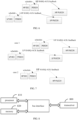
- the semi-static HARQ-ACK codebook may be used to, according to each value in a K1 set which represents HARQ-ACK feedback timing, determine a position set Mc of downlink transmissions of HARQ-ACK feedback in a corresponding slot or sub-slot n on each carrier c (specifically, a currently activated BWP on the carrier), and then determine a HARQ-ACK codebook transmitted in the slot or sub-slot n according to Mc. As shown in FIG.
- a codebook size in slot (n+9) is 6 bits (if multiple PDSCHs can be transmitted by time division multiplexing (TDM) in one slot, multi-bit HARQ-ACK positions can be reserved in each slot; if one PDSCH contains multiple TBs or is configured with code block group (CBG) transmission, each PDSCH may correspond to more bits of HARQ-ACK, thereby changing the codebook size in slot (n+9)).
- TDM time division multiplexing
- CBG code block group
- the advantage of the semi-static HARQ-ACK codebook is that it can ensure that the terminal and network device have the same understanding of the size of the codebook in a relatively stable manner.
- an overhead of the semi-static HARQ-ACK codebook is relatively large, even if only a few transmissions are scheduled in the downlink transmission position set Mc, it still needs to be fed back according to the maximum range.
- a fallback method of the semi-static HARQ-ACK codebook is proposed.
- DCI downlink assignment index
- the dynamic HARQ-ACK codebook may be used to perform HARQ-ACK sorting according to indication of a counter-downlink assignment index (C-DAI) field in DCI for scheduling downlink transmission, and determine a total bit number of the HARQ-ACK codebook according to a total-downlink assignment index (T-DAI) field; thus, the size of the HARQ-ACK codebook can be dynamically adjusted according to actual scheduling at different feedback moments, thereby saving HARQ-ACK feedback overhead.
- C-DAI counter-downlink assignment index
- T-DAI total-downlink assignment index
- PDCCH monitoring occasion (MO) corresponding to an activated BWP on a carrier can be determined first according to K1, K0 (which is slot interval between PDCCH and PDSCH scheduled by the PDCCH, i.e., scheduling timing) and a configured number of repeated transmissions (if configured). If there are multiple carriers, PDCCH MOs on different carriers may not be aligned in time, then the PDCCH MOs on multiple carriers are sorted in chronological order to form a large PDCCH MO set, and one MO of the PDCCH MO set includes MOs that overlap in time domain on multiple carriers.
- C-DAI indicates, in an order of frequency domain and then the time domain, a cumulative number of PDSCHs or PDCCHs that indicate SPS PDSCH release, which have been transmitted up to a current PDCCH MO on a current carrier;
- T-DAI indicates a total number of PDSCHs or PDCCHs that indicate SPS PDSCH release, which have been transmitted on all carriers up to a current PDCCH MO.
- C-DAI is cumulatively counted in frequency domain order in DCI on different carriers on the same MO
- T-DAI has the same value in all DCIs in the same MO and indicates that a total number of DCIs scheduled on all frequency domains in this MO.
- both C-DAI and T-DAI are 2 bits, 1 state of 2 bits can be multiplexed to indicate 1, 5, 9..., 1 state can be multiplexed to indicate 2, 6, 10..., 1 state can be multiplexed to indicate 3, 7, 11..., 1 state can be multiplexed to indicate 4, 8, 12....
- the terminal detects a PDCCH using a certain DCI format (such as one or more of format 1-0, format 1-1, and format 1-2) in a determined PDCCH MO set, and generates a HARQ-ACK codebook according to DAI information (including C-DAI and T-DAI) in the received PDCCH.
- a certain DCI format such as one or more of format 1-0, format 1-1, and format 1-2
- DAI information including C-DAI and T-DAI
- the terminal can determine that a total bit number is 6 (assuming that one PDSCH corresponding to each DAI count is only corresponds to 1-bit HARQ-ACK, if one PDSCH corresponds to A-bit HARQ-ACK, then here is 6*A bit).
- the NR does not support parallel transmission of PUCCH and PUSCH at the same time, no matter on the same carrier or on different carriers.
- PUCCH and PUSCH (without special explanation, generally PUCCH and PUSCH refer to PUCCH and PUSCH that do not use repeated transmission) overlap in time domain resources, in case that a predetermined timeline is met, UCI (which is, generally, HARQ-ACK and CSI) is transferred from PUCCH to PUSCH; in case that there is an SR, the SR is not transmitted on the PUSCH and the SR is discarded.
- one PUSCH is selected according to a predetermined rule, where PUSCH carrying A-CSI is preferentially selected; if PUSCH with PDCCH scheduling (DG PUSCH) and PUSCH without PDCCH scheduling (CG PUSCH, SP-CSI PUSCH, etc.) exist at the same time, DG PUSCH is preferentially selected; after selection according to the above rule, if there are PUSCHs on multiple carriers, PUSCH on a carrier with a smaller carrier index is preferentially selected; if there are multiple non-overlapping PUSCHs in time domain overlapping with PUCCH on the selected carrier, the earliest PUSCH is preferentially selected.
- Definition of the timeline may be that: if PUCCH or PUSCH has a corresponding PDCCH (for example, HARQ-ACK carried by PUCCH is HARQ-ACK of PDSCH with PDCCH scheduling or HARQ-ACK of PDCCH indicating release of downlink SPS resources), the PDCCH for scheduling PDSCH or the PDCCH indicating release of downlink SPS resources is PDCCH corresponding to the PUCCH (also referred to as PDCCH for scheduling the PUCCH), and PDCCH for scheduling PUSCH is PDCCH corresponding to the PUSCH.
- a first symbol of a channel with an earliest start moment in the overlapping PUCCH and PUSCH is taken as a target symbol. If there are multiple channels with the same start moment, a channel is selected randomly, and a first symbol of the selected channel is taken as a target symbol. The target symbol needs to meet the following timeline to perform multiplexing transmission, otherwise it is considered as an error scheduling.
- Timeline 1 the target symbol is not earlier than a first symbol (including cyclic prefix (CP)) after T1mux time after a last symbol of any PDSCH or SPS PDSCH release that requires HARQ-ACK feedback on PUCCH, that is, a time interval between the target symbol and the last symbol of any one of the above PDSCH or SPS PDSCH releases is not less than T1mux time.
- T1mux is related to processing delay of PDSCH, and may be calculated according to a predetermined formula and related parameters. The purpose of the timeline is to ensure that obtaining and preparation of HARQ-ACK can be completed before transmission of finally determined channel for transmitting the HARQ-ACK starts.
- Timeline2 the target symbol is not earlier than a first symbol (including CP) after a T2mux time after a last symbol of any PDCCH (including PDCCH indicating SPS PDSCH release) that schedules PDSCH (if any) and PUSCH (if any), that is, a time interval between the target symbol and the last symbol of any above PDCCH is not less than T2mux time.
- T2mux is related to processing delay of PUSCH, and may be calculated according to a predetermined formula and related parameters.
- this timeline is to ensure that when UCI needs to be transferred to PUSCH, PDCCH for scheduling the PUSCH can be obtained before preparation of the PUCCH starts, so that it is determined that there is no need to prepare UCI transmission on the PUCCH, and transmission preparation including UCI can be completed before transmission of PUSCH starts, that is, obtaining and multiplexing of UCI is completed, and preparation of TB (such as encoding, modulation, scrambling, etc.) is completed. If it is multiplexing between multiple PUCCHs, this T2mux is used to simulate preparation time for CSI and SR multiplexing with HARQ-ACK.
- HARQ-ACK carried by PUCCH does not have a corresponding PDCCH (that is, the HARQ-ACK is HARQ-ACK of SPS PDSCH), at this point, there is no PDCCH for scheduling the PDSCH. If there is no PUSCH or PUSCH has no corresponding PDCCH, it is only needed to check Tlmuxm and is it not needed to check T2mux. If CSI and/or SR are carried on PUCCH, it is not needed to check T1mux, because there is no corresponding PDSCH. Further, if there is no PUSCH or PUSCH has no corresponding PDCCH, it is not needed to check T2mux.
- PUCCH and PUCCH overlap, at least one PUCCH is repeatedly transmitted (that is, occupying multiple slots and repeatedly transmitting UCI in each slot), then, only for overlapping repetitions, repetitions with higher priorities are transmitted and repetitions with lower priorities are discarded, thereby not affecting repetitions that do not overlap.
- PUCCH overlaps with repeatedly transmitted PUSCH in case that the PUSCH uses slot-based repetition transmission (R15 repetition transmission, or repetition type A defined in a protocol), UCI carried by PUCCH is transferred to one or more PUSCH slots that overlap with the PUCCH.
- UCI carried by PUCCH is transferred to an earliest actual repetition PUSCH (which is repetition PUSCH obtained after segmentation based on unavailable symbols, DL symbols, slot boundaries, etc.) that overlaps with the PUCCH and contains more than 1 symbol,.
- the above one or more repetition PUSCHs that overlap with PUCCH need to meet the multiplexing timeline. If multi-slot PUCCH overlaps with single-slot or multi-slot PUSCH, PUSCH overlapping with the PUCCH is discarded to ensure that the repetition transmission of the PUCCH is not interrupted.
- FIG. 4 is a flowchart of an uplink control information transmission method according to an embodiment of the present disclosure. As shown in FIG. 4 , the method includes the following steps:
- the first DCI is a DCI corresponding to a first uplink channel carrying the first HARQ-ACK; and the second HARQ-ACK is HARQ-ACK multiplexed with the first HARQ-ACK.
- the above receiving the first DCI may include: receiving the DCI transmitted by a network device.
- the network device may transmit one or more DCIs, and the terminal may receive one or more DCIs.
- the terminal may receive HARQ-ACK according to the first indication fields in some or all of the multiple first DCIs.
- the first indication field of the first DCI may be one or more bit fields in the first DCI.
- the first indication field is reuse of existing bits in the first DCI, or, the first indication field is a newly added bit in the first DCI.
- the existing bits in the first DCI may be bits in the first DCI already defined in the protocol, and the newly added bit in the first DCI are one or more bits added in the DCI defined in the protocol.
- the above first indication field is used to determine the bit number of the second HARQ-ACK may be that the first indication field indicates information of a total bit number of the second HARQ-ACK, such as a total bit number of the second HARQ-ACK (for example, 0, 1, 2, 4 bits, etc.), or the first indication field indicates a total number of downlink transmissions corresponding to the second HARQ-ACK.
- the downlink transmission corresponding to the second HARQ-ACK specifically includes PDSCH or SPS PDSCH release for which the second HARQ-ACK is needed.
- Whether the second HARQ-ACK exists may be that whether there is a second HARQ-ACK multiplexed with the first HARQ-ACK.
- the first indication field does not indicate whether the second HARQ-ACK exists
- whether the second HARQ-ACK exists can be determined according to the information of the bit number of the second HARQ-ACK, for example, 0 bits means that the second HARQ-ACK does not exist, and non-0 bits means that the second HARQ-ACK exists
- the first indication field does not indicate whether the second HARQ-ACK is multiplexed with a first HARQ-ACK
- whether the second HARQ-ACK is multiplexed with the first HARQ-ACK can be determined according to at least one of the information of the bit number of the second HARQ-ACK and whether the second HARQ-ACK exists.
- the second HARQ-ACK exists, it can be determined that the second HARQ-ACK is multiplexed with the first HARQ-ACK; otherwise, it can be determined that the second HARQ-ACK is not multiplexed with the first HARQ-ACK. If the bit number of the second HARQ-ACK is 0, it can be determined that the second HARQ-ACK is not multiplexed with the first HARQ-ACK; otherwise, it can be determined that the second HARQ-ACK is multiplexed with the first HARQ-ACK.
- the above terminal receiving HARQ-ACK according to the first indication field may include: according to at least one of the following: the bit number of the second HARQ-ACK, whether the second HARQ-ACK exists or whether the second HARQ-ACK is multiplexed with the first HARQ-ACK, transmitting the first HARQ-ACK or transmitting the first HARQ-ACK and the second HARQ-ACK.
- the bit number of the second HARQ-ACK transmitted simultaneously with the first HARQ-ACK can be determined according to the first indication field of the first DCI, thereby receiving HARQ-ACK, so that the network device can receive corresponding HARQ-ACK according to the first indication field of the first DCI, thereby ensuring that the terminal and the network device have the same understanding of the bit number of the HARQ-ACK transmitted by the terminal.
- the second HARQ-ACK uses a dynamic HARQ-ACK codebook
- the foregoing information for determining the total bit number of the second HARQ-ACK may determine that the total bit number of the second HARQ-ACK is 0 or greater than 0.
- Each indication state of the first indication field indicating a corresponding type of information used to determine the total bit number of the second HARQ-ACK may be that the first indication field may determine a total bit number of different second HARQ-ACKs through different indication states.
- some indication states are allowed to be corresponding to the total bit number of the same second HARQ-ACK.
- the first indication field has 3-bit indication information which can indicate 8 indication states, but possible total bit numbers of the second HARQ-ACK are 1-7, then among the 8 indication states, there may be 2 indication states corresponding to the total bit number of the same second HARQ-ACK, or one of the 8 indication states is reserved.
- one indication state is allowed to be corresponding to the total bit numbers of multiple second HARQ-ACKs.
- the first indication field has 2-bit indication information which can indicate 4 indication states, but possible total bit numbers of the second HARQ-ACK are 0-4, then one of the four indication states may be corresponding to two total bit numbers, including 0 bits and 4 bits, and whether the indication state actually indicates 0 bits or 4 bits can be determined by the number of actually received downlink transmissions corresponding to the second HARQ-ACK.
- the indication state indicates 0 bits; if at least one downlink transmission corresponding to the second HARQ-ACK is received, it is determined that the indication state indicates 4 bits.
- the above first indication state may be an indication state defined by the protocol or configured by the network side.
- the first indication state may indicate that the second HARQ-ACK does not exist, or indicate that the second HARQ-ACK is not multiplexed with the first HARQ-ACK, or indicate that the total bit number of the second HARQ-ACK is 0, or indicate that the total number of downlink transmissions corresponding to the second HARQ-ACK is 0.
- Other indication states are respectively corresponding to a type of information used to determine the total bit number, which is greater than 0, of the second HARQ-ACK.
- the above second indication state may be an indication state defined by the protocol or configured by the network side.
- the above first condition and second condition are defined by the protocol or configured by the network side. Different contents can be indicated by the above second indication state under different conditions, thereby reducing the overhead of DCI.
- the second HARQ-ACK may be discarded.
- the information for determining the total bit number of the second HARQ-ACK includes: a total bit number of the second HARQ-ACK, or a total number of downlink transmissions corresponding to the second HARQ-ACK.
- the total bit number of the second HARQ-ACK may be 0 or greater than 0.
- the total number of downlink transmissions corresponding to the second HARQ-ACK may include a total number of transmissions of PDSCH or SPS PDSCH release corresponding to the second HARQ-ACK, that is, a total number of PDCCHs that schedule PDSCH or PDCCHs that indicate SPS PDSCH release.
- the total number of downlink transmissions corresponding to the second HARQ-ACK may include a total number of ⁇ serving cell, PDCCH monitoring occasion ⁇ -pair(s) with PDSCH or SPS PDSCH release, where PDSCH and SPS PDSCH release are corresponding to the second HARQ-ACK.
- the total number of the above PDCCH for scheduling PDSCH and PDCCH indicating SPS PDSCH release may also be referred to as the number of downlink transmissions (including PDSCH, SPS PDSCH release) for which the second HARQ-ACK feedback (including two kinds of feedback information of ACK and NACK) are required.
- the second HARQ-ACK uses a dynamic HARQ-ACK codebook
- the first indication field indicates information for determining the total bit number of the second HARQ-ACK
- the first indication field includes multiple sub-indication fields
- each sub-indication field is used to indicate information for determining the bit number of a sub-codebook corresponding to the each sub-indication field of the second HARQ-ACK.
- the above information for determining the total bit number of the second HARQ-ACK may be the total bit number of the sub-codebooks of the second HARQ-ACK, or the total number of downlink transmissions corresponding to the sub-codebooks of the second HARQ-ACK.
- each sub-indication field may indicate information of the bit number of a sub-codebook.
- the first indication field includes multiple T-DAI fields, which respectively indicate information used to determine the total bit number of each sub-codebook.
- the first indication field is 4 bits
- the first 2 bits of the 4 bits are T-DAI field corresponding to a first sub-codebook, which is used to indicate information for determining the total bit number of the first sub-codebook
- the last 2 bits of the 4 bits are a T-DAI field corresponding to a second sub-codebook, which is used to indicate information for determining the total bit number of the second sub-codebook.
- the first indication field may be expressed as a C-DAI field.
- the first DCI further includes T-DAI and C-DAI (or C-DAI only) for determining a size of the dynamic HARQ-ACK codebook of the first HARQ-ACK, and these fields are different indication fields from the first indication field (corresponding to T-DAI and C-DAI (or only C-DAI) of the second HARQ-ACK) in the first DCI.
- the first condition includes:
- the overlap in the time domain between the first uplink channel and the second uplink channel may be that the first uplink channel and the second uplink channel completely or partially overlap in the time domain.
- the second condition includes:
- the non-overlap in the time domain between the first uplink channel and the second uplink channel may be that there is no time-domain resource overlapping between the first uplink channel and the second uplink channel in the time domain.
- the second HARQ-ACK uses a semi-static HARQ-ACK codebook
- the above third to eleventh indication states may be defined by the protocol or configured by the network.
- the indication states may be multiplexed, for example, the third indication state may be the same as the fifth indication state or the seventh indication state, and the fourth indication state may be the same as the sixth indication state or the eighth indication state.
- the above determining the bit number of the second HARQ-ACK according to the fallback mode may include: determining that the bit number of the second HARQ-ACK is 1.
- the fallback mode may be defined as: only 1-bit second HARQ-ACK is fed back when the following conditions are met: when only one or more SPS PDSCHs are received, and if multiple SPS PDSCHs are received, only one SPS PDSCH requires HARQ-ACK feedback; or, when only one SPS PDSCH release transmitted using DCI format 1-0 is received, and a C-DAI value in DCI is 1; or, when only one PDSCH scheduled using DCI format 1-0 is received, and a C-DAI value in DCI is 1.
- the above first indication field may further include other indication states in addition to the above first to eleventh indication states, which may be specifically defined according to requirements.
- each indication state of the first indication field indicates a corresponding type of information for determining the total bit number of the second HARQ-ACK
- indication information in the first indication field is ignored. That is, at this point, the terminal may not parse or read the indication information in the first indication field; or, regardless of contents of the indication information in the first indication field, the terminal does not receive HARQ-ACK according to the first indication field, and the terminal always assumes that there is no second HARQ-ACK and only transmits the first HARQ-ACK.
- the overlap in the time domain between the second uplink channel that does not carry the second HARQ-ACK and the first uplink channel may be that, for the terminal, there is currently no uplink channel which carries the second HARQ-ACK and which overlaps with the first uplink channel in the time domain.
- the terminal may not parse or read the indication information in the first indication field; or, regardless of contents of the indication information in the first indication field, the terminal does not receive HARQ-ACK according to the first indication field, and the terminal always assumes that there is no second HARQ-ACK and only transmits the first HARQ-ACK.
- the terminal receiving HARQ-ACK according to the first indication field includes:
- the determining, by the terminal, the bit number of the second HARQ-ACK according to the first indication field may include: determining the bit number of the second HARQ-ACK according to an indication state of the first indication field. For example, according to information for determining the total bit number of the second HARQ-ACK, which is indicated by the indication state of the indication field, the bit number of the second HARQ-ACK is determined. Alternatively, according to whether the second HARQ-ACK exists or whether the second HARQ-ACK is multiplexed with the first HARQ-ACK, which is indicated by the first indication field, whether the bit number of the second HARQ-ACK is 0, is determined.
- the determining, by the terminal, the bit number of the second HARQ-ACK according to the first indication field may be performed only when it is determined that the first HARQ-ACK and the second HARQ-ACK need to be simultaneously transmitted on the same channel.
- the determining, by the terminal, the bit number of the second HARQ-ACK according to the first indication field includes: in case that there is overlap in the time domain between the first uplink channel carrying the first HARQ-ACK and the second uplink channel carrying the second HARQ-ACK, determining, by the terminal, the bit number of the second HARQ-ACK according to the first indication field.
- the network device can receive HARQ-ACK according to the same bit number of the second HARQ-ACK, thereby ensuring that the terminal and the network device have the same understanding of the bit number of the second HARQ-ACK.
- the transmitting, by the terminal, HARQ-ACK according to the bit number of the second HARQ-ACK includes:
- the above determination to transmit the second HARQ-ACK may include: according to the first indication field, determining that the bit number of the second HARQ-ACK is greater than 0, or determining that the second HARQ-ACK exists or determining that the second HARQ-ACK is allowed to be multiplexed with the first HARQ-ACK.
- the above determination to not transmit the second HARQ-ACK may include: according to the first indication field, determining that the bit number of the second HARQ-ACK is 0, or determining that the second HARQ-ACK does not exist or determining that the second HARQ-ACK is not multiplexed with the first HARQ-ACK.
- the simultaneously transmitting the first HARQ-ACK and the second HARQ-ACK on the same channel, according to the bit number of the second HARQ-ACK may be that the bit number of the second HARQ-ACK transmitted on this channel is the above bit number of the second HARQ-ACK determined according to the first indication field, and the bit number of the first HARQ-ACK may be the bit number determined according to HARQ-ACK codebook type configured by the network side, actual reception situation and related configuration parameters in the related art, in accordance with a method specified in the protocol; or the bit number of the first HARQ-ACK may be the bit number determined in a pre-negotiation manner between the terminal and the network device.
- the bit number of the first HARQ-ACK is not limited, and it is assumed that the network side and the terminal can always have the same understanding of the bit number of the first HARQ-ACK.
- the simultaneously transmitting the first HARQ-ACK and the second HARQ-ACK on the same channel may include: simultaneously transmitting the first HARQ-ACK and the second HARQ-ACK on the first uplink channel or the second uplink channel.
- the second uplink channel may be a channel different from the first uplink channel, and may be PUCCH corresponding to the first HARQ-ACK or an uplink channel with the same priority as the first uplink channel or the first HARQ-ACK.
- the simultaneously transmitting the first HARQ-ACK and the second HARQ-ACK on the same channel, according to the bit number of the second HARQ-ACK may include: taking the above bit number of the second HARQ-ACK determined according to the first indication field as a reference bit number, and simultaneously transmitting the first HARQ-ACK and the second HARQ-ACK on the same channel according to the reference bit number, which specifically includes:
- the determining PUCCH resource includes at least one of the following:
- the determining PUCCH resource set includes: according to a sum of the bit number of the first HARQ-ACK and the reference bit number of the second HARQ-ACK, determining the PUCCH resource set.
- the determining a minimum number of resource blocks (RBs) of a PUCCH resource for carrying the first HARQ-ACK and the second HARQ-ACK includes:
- the determining one PUCCH resource in at least one PUCCH resource for carrying channel state information (CSI), includes: according to a sum of the bit number of the first HARQ-ACK, the reference bit number of the second HARQ-ACK and the bit number of CSI simultaneously transmitted with the first HARQ-ACK and the second HARQ-ACK, selecting a PUCCH resource from at least one PUCCH resource for carrying CSI.
- CSI channel state information
- the simultaneously transmitting the first HARQ-ACK and the second HARQ-ACK on the same channel, according to the reference bit number further includes: in case that CSI and HARQ-ACK are transmitted simultaneously, at least based on the reference bit number of the second HARQ-ACK, determining whether to perform CSI discarding and/or discarding part of CSI.
- whether to perform CSI discarding and/or discarding part of CSI is determined.
- the CSI, the second HARQ-ACK and the first HARQ-ACK are directly transmitted simultaneously on the same uplink channel; if it is determined to discard CSI, it is further determined which part of the CSI is reserved and which part of the CSI is discarded, and the reserved part of the CSI, the second HARQ-ACK and the first HARQ-ACK are simultaneously transmitted on the same uplink channel.
- the determining a target resource for carrying HARQ-ACK on the PUSCH based on the reference bit number includes:
- the simultaneously transmitting the first HARQ-ACK and the second HARQ-ACK on the same channel according to the reference bit number includes:
- a negative acknowledgment NACK bit is added at an end of an actual bit sequence of the second HARQ-ACK to obtain a target bit sequence, and a bit number of the target bit sequence is taken as the reference bit number.
- the priority of the first uplink channel is higher than the priority of the second uplink channel carrying the second HARQ-ACK.
- the second HARQ-ACK with lower priority can be multiplexed with the first HARQ-ACK with higher priority.
- the first uplink channel is one of PUCCH and PUSCH
- the second uplink channel carrying the second HARQ-ACK is one of PUCCH and PUSCH
- channel types of the first uplink channel and the second uplink channel are the same or different.
- the first uplink channel and the second uplink channel may be PUCCH or PUSCH and the channel types of the first uplink channel and the second uplink channel are the same or different, it can be realized that HARQ-ACKs carried on uplink channels of same or different types can be multiplexed.
- whether the first indication field exists in the first DCI is determined according to configuration of high-layer signaling; or, the first indication field always exists in the first DCI by default.
- the terminal may determine whether the first indication field is in the first DCI according to high-layer signaling, so that when it is determined that the first indication field exists in the first DCI, DCI is detected according to a size of DCI in which the first indication field exists.
- the high-layer signaling may explicitly or implicitly indicate whether the first indication field exists in the first DCI.
- the high-layer signaling directly informs whether the first indication field exists in the first DCI; or, the high-layer signaling may inform whether to support multiplexing transmission of channels with different priorities, if supporting multiplexing transmission of channels with different priorities, it means that the first DCI includes the first indication field; or, the high-layer signaling may inform whether to support multiplexing transmission of the first HARQ-ACK and the second HARQ-ACK, and when configuring to support multiplexing transmission of the first HARQ-ACK and the second HARQ-ACK, it is determined that the first indication field exists in the first DCI.
- the foregoing defaulting that the first indication field always exists in the first DCI may mean that the terminal and the network device consider that the first indication field always exists in the first DCI.
- Whether to support multiplexing transmission of the first HARQ-ACK and the second HARQ-ACK can be dynamically determined through an indication state of the first indication field. For example, when the indication state of the first indication field indicates that there is no transmission of second HARQ-ACK or the second HARQ-ACK is not multiplexed with the first HARQ-ACK, it means that the multiplexing transmission of the first HARQ-ACK and the second HARQ-ACK is not supported, or it means that the second HARQ-ACK is scheduled, or it means that the second uplink channel does not overlap with the first uplink channel.
- the first DCI is a DCI used to schedule PDSCH that requires HARQ-ACK feedback on the PUCCH, or, the first DCI is a DCI used to indicate SPS PDSCH release that requires HARQ-ACK feedback on the PUCCH; or, in case that the first uplink channel is PUSCH, the first DCI is a DCI for scheduling the PUSCH.
- the above first DCI being a DCI used to schedule PDSCH that requires HARQ-ACK feedback on the PUCCH may be understood as that the first DCI is used to schedule PDSCH, and the PDSCH is a PDSCH that requires HARQ-ACK feedback on the PUCCH.
- the above first DCI being a DCI used to indicate SPS PDSCH release that requires HARQ-ACK feedback on the PUCCH may be understood as that the first DCI is used to indicate the SPS PDSCH release, and the SPS PDSCH release is a SPS PDSCH release that requires HARQ-ACK feedback on the PUCCH.
- values of first indication fields in the multiple first DCIs are the same, or the terminal transmits HARQ-ACK according to a first indication field in the last DCI.
- values of the first indication fields of the multiple DCIs are the same, and the terminal can receive HARQ-ACK according to the first indication field of any DCI.
- the terminal receives HARQ-ACK only according to the first indication field in the last DCI.
- the priority of the first HARQ-ACK is higher than the priority of the second HARQ-ACK; or the first HARQ-ACK is HARQ-ACK of a unicast, and the second HARQ-ACK is HARQ-ACK of a multicast.
- HARQ-ACKs of different priorities can be multiplexed, and HARQ-ACK of the unicast and HARQ-ACK of the multicast can also be multiplexed.
- overlap in the time domain mentioned in the present disclosure generally refers to overlap in the time domain in the same carrier group, for example, in the same PUCCH carrier group in case of carrier aggregation (CA), or in the same master carrier group (MCG) or the same secondary carrier group (SCG) in case of dual connectivity (DC), or in the same PUCCH carrier group in a certain carrier group (MCG or SCG) in case of a combination of CA and DC; and the above carriers can be replaced by cells, which are equivalent to carriers.
- CA carrier aggregation
- MCG master carrier group
- SCG secondary carrier group
- DC dual connectivity
- the terminal receives the first downlink control information DCI, and the first indication field of the first DCI is used to determine at least one of the following: the bit number of the second HARQ-ACK, whether the second HARQ-ACK exists, or whether the second HARQ-ACK is multiplexed with the first HARQ-ACK; and the terminal receives HARQ-ACK according to the first indication field; where the first DCI is a DCI corresponding to the first uplink channel carrying the first HARQ-ACK, and the second HARQ-ACK is HARQ-ACK multiplexed with the first HARQ-ACK.
- the terminal receives HARQ-ACK according to the first indication field, it can be avoided that when multiple HARQ-ACKs are simultaneously transmitted, the terminal and the network device have inconsistent understanding of the bit numbers of HARQ-ACKs transmitted by the terminal.
- FIG. 5 is a flowchart of an uplink control information reception method according to an embodiment of the present disclosure. As shown in FIG. 5 , the method includes the following steps:
- the first DCI is a DCI corresponding to a first uplink channel carrying the first HARQ-ACK; and the second HARQ-ACK is HARQ-ACK multiplexed with the first HARQ-ACK.
- the second HARQ-ACK uses a dynamic HARQ-ACK codebook
- the information for determining the total bit number of the second HARQ-ACK includes: a total bit number of the second HARQ-ACK, or a total number of downlink transmissions corresponding to the second HARQ-ACK.
- the first indication field indicates information for determining the total bit number of the second HARQ-ACK
- the first indication field includes multiple sub-indication fields
- each sub-indication field is used to indicate information for determining the bit number of a sub-codebook corresponding to the each sub-indication field of the second HARQ-ACK.
- the second HARQ-ACK uses a semi-static HARQ-ACK codebook
- the first condition includes:
- the second condition includes:
- indication information in the first indication field can be arbitrarily set.
- the first indication field includes the third indication state and the fourth indication state
- indication information in the first indication field can be arbitrarily set.
- the receiving, by the network device, HARQ-ACK according to the first indication field includes:
- the receiving, by the network device, HARQ-ACK according to the bit number of the second HARQ-ACK includes:
- the determining, by the network device, a bit number of the second HARQ-ACK, according to the first indication field includes: in case that there is overlap in the time domain between the first uplink channel carrying the first HARQ-ACK and the second uplink channel carrying the second HARQ-ACK, determining, by the network device, the bit number of the second HARQ-ACK, according to the first indication field.
- the priority of the first uplink channel is higher than the priority of the second uplink channel carrying the second HARQ-ACK.
- the first uplink channel is one of PUCCH and PUSCH
- the second uplink channel carrying the second HARQ-ACK is one of PUCCH and PUSCH
- channel types of the first uplink channel and the second uplink channel are the same or different.
- whether the first indication field exists in the first DCI is determined according to configuration of high-layer signaling; or, the first indication field always exists in the first DCI by default.
- the first DCI is a DCI used to schedule PDSCH that requires HARQ-ACK feedback on the PUCCH, or, the first DCI is a DCI used to indicate SPS PDSCH release that requires HARQ-ACK feedback on the PUCCH; or, in case that the first uplink channel is PUSCH, the first DCI is a DCI for scheduling the PUSCH.
- values of first indication fields in the multiple first DCIs are the same, or HARQ reception is performed according to a first indication field in the last DCI.
- the priority of the first HARQ-ACK is higher than the priority of the second HARQ-ACK; or the first HARQ-ACK is HARQ-ACK of a unicast, and the second HARQ-ACK is HARQ-ACK of a multicast.
- the first indication field is reuse of existing bits in the first DCI, or the first indication field is a newly added bit in the first DCI.
- this embodiment is an implementation manner of the corresponding network device in the embodiment shown in FIG. 4 , and the specific implementation may refer to relevant description of the embodiment shown in FIG. 4 with the same beneficial effects being achieved, which will not be repeated in this embodiment to avoid repetition.
- HARQ-ACK of lower priority uses a dynamic codebook, and CBG transmission is not configured, that is, at least 2-bit T-DAI is required to indicate a total bit number of the low-priority dynamic codebook (if CBG is configured, 4-bit T-DAI is required, where the first 2 bits indicate T-DAI of a first sub-codebook, and the last 2 bits indicate T-DAI of a second sub-codebook, and a bit size of each sub-codebook is determined in a manner similar to the process in this embodiment which will not be repeated); high-priority HARQ-ACK (i.e., the above first HARQ-ACK) using any codebook can use the method in this embodiment (for example, high-priority HARQ-ACK only needs to determine high-priority HARQ-ACK feedback sequence based on the used codebook according to a method defined by the protocol); assuming that the terminal is used to support multiplexing transmission when low-
- the network device transmits DCI according to a condition of including the first indicator field, and the terminal receives the DCI according to the condition of including the first indicator field. It is assumed that according to scheduling of the network device, on an active BWP on a primary carrier, transmission of low-priority PUCCH (LP PUCCH) and transmission of high-priority PUCCH (HP PUCCH) overlap in the time domain, and the two PUCCHs are used to carry HARQ-ACKs, the priorities of the two PUCCHs are determined according to priorities of HARQ-ACK codebooks carried by the two PUCCHs, and the priorities of HARQ-ACK codebooks may be dynamically indicated by a priority indication field in DCI for scheduling PDSCH.
- LP PUCCH low-priority PUCCH
- HP PUCCH high-priority PUCCH
- the network device may operate as follows.
- the network device schedules 6 downlink transmissions (such as PDSCH or SPS PDSCH release) corresponding to low-priority HARQ-ACK, and each downlink transmission is corresponding to 1-bit HARQ-ACK, that is, the network device determines that low-priority PUCCH carries 6-bit low-priority HARQ-ACK, as shown in FIG.
- the network device determines A-bit high-priority HARQ-ACK is transmitted in high-priority PUCCH, according to the number of downlink transmissions corresponding to high-priority HARQ-ACKs scheduled by the network device, a bit number of HARQ-ACK corresponding to each downlink transmission and a type (dynamic or semi-static) of high-priority HARQ-ACK codebook.
- mapping table 1 in accordance with a mode 1 (each indication state of a first indication field indicates a corresponding type of information used to determine a total bit number of the second HARQ-ACK), or according to the following mapping table 4 in accordance with a mode 3 (i.e., implementation of the second indication state in the embodiment shown in FIG.
- the network device sets a 2-bit first indication field in DCI (which is a DCI for scheduling PDSCH that that requires high-priority HARQ-ACK transmitted on high-priority PUCCH) corresponding to HP PUCCH to "01" and a value of corresponding V T ⁇ DAI DL is "2"; or, according to the following mapping table 2 in accordance with a mode 2 (i.e., implementation of the first indication state in the embodiment shown in FIG.
- DCI which is a DCI for scheduling PDSCH that that requires high-priority HARQ-ACK transmitted on high-priority PUCCH
- the network device sets a 2-bit first indication field in DCI corresponding to HP PUCCH to "10" and a value of corresponding V T ⁇ DAI DL is "2"; or, according to the following mapping table 3 in accordance with a mode 2 (i.e., implementation of the first indication state in the embodiment shown in FIG.
- the network device sets a 3-bit first indication field in DCI corresponding to HP PUCCH to "011" and a value of corresponding V T ⁇ DAI DL is "3", it means that there are 6 DCI transmissions corresponding to low priority for scheduling 6 PDSCH or SPS PDSCH release corresponding to low-priority HARQ-ACK, thereby helping the terminal determine that the bit number of low-priority HARQ-ACK is 6 bits (that is, the bit number of the second HARQ-ACK is 6).
- the network device receives HARQ-ACK according to the A-bit high-priority HARQ-ACK and the 6-bit low-priority HARQ-ACK on a PUCCH resource which is determined according to a multiplexing transmission scheme of high-priority and low-priority HARQ-ACKs (the specific multiplexing transmission scheme is not limited, for example, the multiplexing transmission scheme may be defined in the protocol or newly defined in the subsequent protocol version), and obtains A-bit high-priority HARQ-ACK and 6-bit low-priority HARQ-ACK, respectively.
- the terminal side may operate as follows.
- the terminal can obtain a value of V T ⁇ DAI DL indicated by the 2-bit first indication field as "2", or obtain a value of V T ⁇ DAI DL indicated by the 3-bit first indication field as "3"; because more than 2 DCIs have been received, it is judged that a total number of transmitted DCIs indicated by V T ⁇ DAI DL is 6 (which value among 2, 6, and 10 corresponds to the same indication state may be determined by combining how many DCIs have been received, because assuming that in multiplexing counting of the mode 4 and there is no continuous loss of 4 DCIs, then, if received DCI has exceeded 2 but not exceeded 6, it can be determined that the current first indication field indicates 6 DCIs); according to the number of downlink transmissions scheduled by DCI and a bit number of HARQ-ACK feedback corresponding to each downlink transmission, it is determined that the low-priority HARQ-ACK is of a total 6 bits (because there
- the terminal determines A-bit high-priority HARQ-ACK is transmitted in high-priority PUCCH, according to the number of received downlink transmissions corresponding to high-priority HARQ-ACKs scheduled by the network device, a bit number of HARQ-ACK corresponding to each downlink transmission and a type (dynamic or semi-static) of high-priority HARQ-ACK codebook.
- the terminal simultaneously transmits A-bit high-priority HARQ-ACK and 6-bit low-priority HARQ-ACK on a PUCCH resource which is determined according to a multiplexing transmission scheme of high-priority and low-priority HARQ-ACKs.
- HP PUCCH high-priority PUCCH
- LP PUCCH low-priority PUCCH
- case 1 the network device schedules a low-priority transmission, but LP PUCCH carrying low-priority HARQ-ACK does not overlap with HP PUCCH in the time domain; case 2: the network device does not schedule low-priority transmissions, and thus there is no LP PUCCH).
- DCI corresponding to high-priority PUCCH includes a first indication field (which may be 2 bits or 3 bits according to different mapping tables).
- the network device transmits DCI according to a condition of including the first indicator field, and the terminal receives the DCI according to the condition of including the first indicator field.
- the network device may operate as follows.
- the network device schedules B downlink transmissions (such as PDSCH or SPS PDSCH release) corresponding to low-priority HARQ-ACK, and each downlink transmission is corresponding to 1-bit HARQ-ACK, that is, the network device determines that low-priority PUCCH carries B-bit low-priority HARQ-ACK.
- B downlink transmissions such as PDSCH or SPS PDSCH release
- each downlink transmission is corresponding to 1-bit HARQ-ACK
- the network device determines A-bit high-priority HARQ-ACK is transmitted in high-priority PUCCH, according to the number of downlink transmissions corresponding to high-priority HARQ-ACKs scheduled by the network device, a bit number of HARQ-ACK corresponding to each downlink transmission and a type (dynamic or semi-static) of high-priority HARQ-ACK codebook.
- mapping table 4 a 2-bit first indication field in DCI corresponding to HP PUCCH is set to "00" and a value of corresponding V T ⁇ DAI DL is "0"; or, according to the following mapping table 3 in accordance with the mode 2, a 3-bit first indication field in DCI corresponding to HP PUCCH is set to "000" and a value of corresponding V T ⁇ DAI DL is "0", it means that there is no overlap between LP PUCCH and HP PUCCH, that is, no low-priority HARQ-ACK needs to be transmitted together with high-priority HARQ-ACK, thereby helping the terminal determine that a bit number of low-priority HARQ-ACK transmitted together with the high-priority HARQ-ACK is 0, that is, no low-priority HARQ-ACK needs to be transmitted together with the high-priority HARQ-ACK needs to be transmitted together with the high-priority HARQ-ACK, thereby helping the terminal determine that a bit number of low
- the network device receives A-bit high-priority HARQ-ACK on HP PUCCH and receives B-bit low-priority HARQ-ACK on LP PUCCH, respectively.
- the network device only receives A-bit high-priority HARQ-ACK on HP PUCCH.
- the terminal side may operate as follows.
- the terminal may not read this indication field or does not care about indication state of the indication field.
- V T ⁇ DAI DL being "0" indicated by a 2-bit or 3-bit first indication field in a received DCI corresponding to HP PUCCH
- the terminal determines that B-bit low-priority HARQ-ACK is transmitted in LP PUCCH, directly according to the number of received downlink transmissions corresponding to low-priority HARQ-ACK, a bit number of HARQ-ACK corresponding to each downlink transmission and a type (dynamic or semi-static) of low-priority HARQ-
- the terminal transmits B-bit low-priority HARQ-ACK on LP PUCCH, and transmits A-bit high-priority HARQ-ACK on HP PUCCH, respectively.
- the terminal determines that A-bit high-priority HARQ-ACK is transmitted in HP PUCCH (that is, there is no low-priority HARQ-ACK at this moment) according to the number of received downlink transmissions corresponding to high-priority HARQ-ACK, a bit number of HARQ-ACK corresponding to each downlink transmission and a type (dynamic or semi-static) of high-priority HARQ-ACK codebook, and transmits only the A-bit high-priority HARQ-ACK on HP PUCCH.
- low-priority HARQ-ACK uses a semi-static codebook type, and a first indication field included in DCI (that is, the above first DCI) corresponding to HP PUCCH is 1 or 2 bits, and other assumptions are the same as that in the example 1. Details are as follows.
- the first indication field may be 1 bit, which is corresponding to a mode 4 (i.e., implementation of the third indication state and the fourth indication state in the embodiment shown in FIG. 4 ); the first indication field may be 2 bit, which is corresponding to a mode 5 (i.e., implementation of the fourth indication state and the fifth indication state in the embodiment shown in FIG. 4 ) and a mode 6 (i.e., implementation of the seventh indication state and the eighth indication state in the embodiment shown in FIG. 4 ).
- a mode 4 i.e., implementation of the third indication state and the fourth indication state in the embodiment shown in FIG. 4
- the first indication field may be 2 bit, which is corresponding to a mode 5 (i.e., implementation of the fourth indication state and the fifth indication state in the embodiment shown in FIG. 4 ) and a mode 6 (i.e., implementation of the seventh indication state and the eighth indication state in the embodiment shown in FIG. 4 ).
- the network device transmits 3 bits, the terminal receives 1 bit, and multiplexing transmission is performed according to A1 bit.
- the 3 bits are transmitted together with AN bits.
- the network device may operate as follows.
- the network device schedules 3 downlink transmissions (such as PDSCH or SPS PDSCH release) corresponding to low-priority HARQ-ACK (i.e., the above second HARQ-ACK), and each downlink transmission is corresponding to 1-bit HARQ-ACK, as shown in FIG. 2 , since fallback of the semi-static codebook is not satisfied (1-bit HARQ-ACK transmitted), the network device determines that low-priority HARQ-ACK carried in LP PUCCH is determined according to the semi-static codebook, i.e., determined according to the K1 set, and is 6-bit HARQ-ACK as shown in FIG. 2 .
- the network device determines that A-bit high-priority HARQ-ACK is transmitted in high-priority PUCCH, according to the number of downlink transmissions corresponding to high-priority HARQ-ACKs (i.e., the above first HARQ-ACK) scheduled by the network device, a bit number of HARQ-ACK corresponding to each downlink transmission and a type (dynamic or semi-static) of high-priority HARQ-ACK codebook.
- the network device sets a 1-bit first indication field in DCI corresponding to HP PUCCH to "1"; or, according to the following mapping table 7 in accordance with the above mode 6, the network device sets a 1-bit first indication field in DCI corresponding to HP PUCCH to "0"; or, according to the following mapping table 8 in accordance with the above mode 7 (that is, implementation of the ninth indication state, the tenth indication state and the eleventh indication state in the embodiment shown in FIG.
- the network device sets a 2-bit first indication field in DCI corresponding to HP PUCCH to "10", it means that a bit number of the low-priority HARQ-ACK is determined according to a size of the semi-static codebook, thereby helping the terminal determine that the bit number of the low-priority HARQ-ACK is 6 bits.
- the network device receives HARQ-ACK according to the A-bit high-priority HARQ-ACK and the 6-bit low-priority HARQ-ACK on a PUCCH resource which is determined according to a multiplexing transmission scheme of high-priority and low-priority HARQ-ACKs, and obtains A-bit high-priority HARQ-ACK and 6-bit low-priority HARQ-ACK, respectively.
- Table 5 correspondence of indication state of 1-bit first indication field (corresponding to the above mode 4) first indication field bit number of low-priority HARQ-ACK 0 1 1 determined according to a size of the semi-static codebook Table 6: correspondence of indication state of 1-bit first indication field (corresponding to the above mode 5) first indication field bit number of low-priority HARQ-ACK 0 0 (no low-priority HARQ-ACK or not support multiplexing transmission of low-priority HARQ-ACK and high-priority HARQ-ACK) 1 determined according to a size of the semi-static codebook Table 7: correspondence of indication state of 1-bit first indication field (corresponding to the above mode 6) first indication field bit number of low-priority HARQ-ACK 0 0 (no low-priority HARQ-ACK or not support multiplexing transmission of low-priority HARQ-ACK and high-priority HARQ-ACK) or determined according to a size of the semi-static codebook 1 1 Table 8:
- the terminal side may operate as follows.
- the mapping table corresponding to the same mode adopted by the network device it can be determined according to the 1-bit first indication field or the 2-bit first indication field that the bit number of low-priority HARQ-ACK is determined according to the size of the semi-static codebook.
- the terminal judges, based on actually received DCI corresponding to the low-priority HARQ-ACK, that the first indication field being "0" indicates that the bit number of the low-priority HARQ-ACK is determined according to the size of the semi-static codebook.
- the terminal determines that the low-priority HARQ-ACK has a total of 6 bits.
- the terminal determines A-bit high-priority HARQ-ACK is transmitted in high-priority PUCCH, according to the number of received downlink transmissions corresponding to high-priority HARQ-ACKs, a bit number of HARQ-ACK corresponding to each downlink transmission and a type (dynamic or semi-static) of high-priority HARQ-ACK codebook.
- the terminal simultaneously transmits A-bit high-priority HARQ-ACK and 6-bit low-priority HARQ-ACK on a PUCCH resource which is determined according to a multiplexing transmission scheme of high-priority and low-priority HARQ-ACKs.
- low-priority HARQ-ACK uses a semi-static codebook type, and a first indication field included in DCI corresponding to HP PUCCH is 1 or 2 bits, and other assumptions are the same as that in the example 2. Details are as follows.
- the network device does not transmit LP AN, and a specific state in DCI indicates that there is no LP AN multiplexing, then only HP AN is transmitted.
- a specific state in DCI indicates that there is no LP AN multiplexing, then only HP AN is transmitted.
- it can be determined that there is no LP AN, according to the first indication field.
- it is determined to ignore the first indication field and only HP AN is transmitted, or it is considered that there is no overlap and then it is not necessary to determine a bit number of LP AN according to the first indication field.
- the network device may operate as follows.
- Case 1 it is assumed that the network device schedules more than one downlink transmissions (such as PDSCH or SPS PDSCH release) corresponding to low-priority HARQ-ACK, and each downlink transmission is corresponding to 1-bit HARQ-ACK, that is, the network device determines that low-priority PUCCH carries B-bit low-priority HARQ-ACK (i.e., the above second HARQ-ACK) according to a determination method of the semi-static codebook.
- case 2 it is assumed that the network device does not schedule low-priority transmissions, then there is no transmission of low-priority PUCCH carrying low-priority HARQ-ACK.
- the network device determines that A-bit high-priority HARQ-ACK is transmitted in high-priority PUCCH, according to the number of downlink transmissions corresponding to high-priority HARQ-ACKs (i.e., the above first HARQ-ACK) scheduled by the network device, a bit number of HARQ-ACK corresponding to each downlink transmission and a type (dynamic or semi-static) of high-priority HARQ-ACK codebook.
- the network device may set the first indication field to a fixed value or an arbitrary value, and the terminal will not read this value or determine a bit number of low-priority HARQ-ACK according to this value.
- a 1-bit first indication field in DCI corresponding to HP PUCCH is set to "0"; or, according to the mapping table 8 in accordance with the above mode 7, a 2-bit first indication field in DCI corresponding to HP PUCCH is set to "00", it means that there is no overlap between LP PUCCH and HP PUCCH, that is, no low-priority HARQ-ACK needs to be transmitted together with high-priority HARQ-ACK, thereby helping the terminal determine that a bit number of low-priority HARQ-ACK transmitted together with the high-priority HARQ-ACK is 0, that is, no low-priority HARQ-ACK needs to be transmitted together with the high-priority HARQ-ACK.
- the network device receives A-bit high-priority HARQ-ACK on HP PUCCH and receives B-bit low-priority HARQ-ACK on LP PUCCH, respectively.
- the network device only receives A-bit high-priority HARQ-ACK on HP PUCCH.
- the terminal side may operate as follows.
- the terminal may not read this indication field or does not care about indication state of the indication field.
- the terminal may not read this indication field or does not care about indication state of the indication field.
- the terminal determines that B-bit low-priority HARQ-ACK is transmitted in LP PUCCH, directly according to the number of received downlink transmissions corresponding to low-priority HARQ-ACK, a bit number of HARQ-ACK corresponding to each downlink transmission and a type (dynamic or semi-static) of low-priority HARQ-ACK codebook, and determines that A-bit high-priority HARQ-ACK is transmitted in HP PUCCH according to the number of received downlink transmissions corresponding to high-priority HARQ-ACK, a bit number of HARQ-ACK corresponding to each downlink transmission and a type (dynamic or semi-static) of high-priority HARQ-ACK codebook.
- the terminal transmits B-bit low-priority HARQ-ACK on LP PUCCH, and transmits A-bit high-priority HARQ-ACK on HP PUCCH, respectively.
- the terminal determines that A-bit high-priority HARQ-ACK is transmitted in HP PUCCH (that is, there is no low-priority HARQ-ACK at this moment) according to the number of received downlink transmissions corresponding to high-priority HARQ-ACK, a bit number of HARQ-ACK corresponding to each downlink transmission and a type (dynamic or semi-static) of high-priority HARQ-ACK codebook, and transmits only the A-bit high-priority HARQ-ACK on HP PUCCH.
- the above steps performed by the terminal and the network device are in no particular order, which are only to illustrate specific behaviors.
- one DCI schedules one PDSCH and one PDSCH is corresponding to 1-bit feedback; if one DCI schedules multiple PDSCHs or one PDSCH is corresponding to multi-bit feedback (for example, in case of multiple TB or configured CBG), it only affects a result of a total bit number determined according to T-DAI and does not affect the above process of determining the bit number according to the first indication field, and the above method can be reused after corresponding replacement of the determined bit numbers.
- 2-bit and 3-bit first indication fields are only examples, and 1 bit may also indicate different accumulated DCI numbers by means of modulo 2, and of course it may also be greater than 2 or 3 bits, etc. Corresponding relationship between different indication states and corresponding DCI numbers may also be changed, which are included in the embodiments of the present disclosure.
- a first indication field in DCI corresponding to HARQ-ACK of a first type or corresponding to an uplink channel carrying the HARQ-ACK of the first type can be used to determine a bit number of HARQ-ACK of a second type, thereby preventing transmission of HARQ-ACK of the first type from being affected by changes of the bit number of the HARQ-ACK of the second type due to packet loss.
- FIG. 8 is a structural diagram of a terminal according to an embodiment of the present disclosure. As shown in FIG. 8 , the terminal includes a memory 820, a transceiver 800, and a processor 810.
- the memory 820 is used to store a computer program.
- the transceiver 800 is used to send and receive data under control of the processor 810.
- the processor 810 is used to read the computer program in the memory 820 and perform the following operations:
- the first DCI is a DCI corresponding to a first uplink channel carrying the first HARQ-ACK; and the second HARQ-ACK is HARQ-ACK multiplexed with the first HARQ-ACK.
- the transceiver 800 is used to send and receive data under control of the processor 810.
- a bus architecture may include any number of interconnected bus and bridge. Specifically, various circuits of one or more processors, which are represented by the processor 810, and one or more memories, which are represented by the memory 820, are linked together.
- the bus architecture may link various other circuits, such as a peripheral device, voltage regulator and a power management circuit together. These features are well known in this field; therefore, this disclosure does not make further description on these features.
- the bus interface provides an interface.
- the transceiver 800 may be multiple elements, including a transmitter and a receiver and provide units, which communicate with other devices on the transmission medium.
- the transmission medium includes wireless channels, wired channels, and optical cables.
- a user interface 830 may also be an interface capable of externally connecting required devices, and the connected devices include but are not limited to keypads, displays, speakers, microphones, joysticks, etc.
- the processor 810 is responsible for managing the bus architecture and the normal processing.
- the memory 820 may be used to store data used by the processor 810 for performing operations.
- the processor 810 may be a central processing unit (CPU), an application specific integrated circuit (ASIC), a field-programmable gate array (FPGA) or a complex programmable logic device (CPLD).
- the processor may also adopt multi-core architecture.
- the processor is used to call the computer program stored in the memory, and execute any method provided in the embodiments of the present disclosure according to obtained executable instructions.
- the processor and the memory may also be physically separated.
- a first DCI is received, where a first indication field of the first DCI is used to determine at least one of the following: a bit number of a second HARQ-ACK, whether the second HARQ-ACK exists, whether the second HARQ-ACK is multiplexed with a first HARQ-ACK;
- HARQ-ACK is transmitted according to the first indication field.
- the first DCI is a DCI corresponding to a first uplink channel carrying the first HARQ-ACK; and the second HARQ-ACK is HARQ-ACK multiplexed with the first HARQ-ACK.
- the second HARQ-ACK uses a dynamic HARQ-ACK codebook
- the information for determining the total bit number of the second HARQ-ACK includes: a total bit number of the second HARQ-ACK, or a total number of downlink transmissions corresponding to the second HARQ-ACK.
- the first indication field indicates information for determining the total bit number of the second HARQ-ACK
- the first indication field includes multiple sub-indication fields
- each sub-indication field is used to indicate information for determining the bit number of a sub-codebook corresponding to the each sub-indication field of the second HARQ-ACK.
- the second HARQ-ACK uses a semi-static HARQ-ACK codebook
- the first condition includes:
- the second condition includes:
- each indication state of the first indication field indicates a corresponding type of information for determining the total bit number of the second HARQ-ACK, if it is determined that there is overlap in the time domain between the second uplink channel that does not carry the second HARQ-ACK and the first uplink channel, indication information in the first indication field is ignored.
- the first indication field includes the third indication state and the fourth indication state
- indication information in the first indication field is ignored.
- the receiving HARQ-ACK according to the first indication field includes:
- the receiving HARQ-ACK according to the bit number of the second HARQ-ACK includes:
- the determining the bit number of the second HARQ-ACK according to the first indication field includes: in case that there is overlap in the time domain between the first uplink channel carrying the first HARQ-ACK and the second uplink channel carrying the second HARQ-ACK, determining the bit number of the second HARQ-ACK according to the first indication field.
- the priority of the first uplink channel is higher than the priority of the second uplink channel carrying the second HARQ-ACK.
- the first uplink channel is one of PUCCH and PUSCH
- the second uplink channel carrying the second HARQ-ACK is one of PUCCH and PUSCH
- channel types of the first uplink channel and the second uplink channel are the same or different.
- whether the first indication field exists in the first DCI is determined according to configuration of high-layer signaling; or, the first indication field always exists in the first DCI by default.
- the first DCI is a DCI used to schedule PDSCH that requires HARQ-ACK feedback on the PUCCH, or, the first DCI is a DCI used to indicate SPS PDSCH release that requires HARQ-ACK feedback on the PUCCH; or, in case that the first uplink channel is PUSCH, the first DCI is a DCI for scheduling the PUSCH.
- values of first indication fields in the multiple first DCIs are the same, or the terminal transmits HARQ-ACK according to a first indication field in the last DCI.
- the priority of the first HARQ-ACK is higher than the priority of the second HARQ-ACK; or the first HARQ-ACK is HARQ-ACK of a unicast, and the second HARQ-ACK is HARQ-ACK of a multicast.
- the first indication field is reuse of existing bits in the first DCI, or the first indication field is a newly added bit in the first DCI.
- FIG. 9 is a structural diagram of a network device according to an embodiment of the present disclosure.
- the network device includes a memory 920, a transceiver 900, and a processor 910.
- the memory 920 is used to store a computer program.
- the transceiver 900 is used to send and receive data under control of the processor 910.
- the processor 910 is used to read the computer program in the memory 920 and perform the following operations:
- the first DCI is a DCI corresponding to a first uplink channel carrying the first HARQ-ACK; and the second HARQ-ACK is HARQ-ACK multiplexed with the first HARQ-ACK.
- the transceiver 900 is used to send and receive data under control of the processor 910.
- a bus architecture may include any number of interconnected bus and bridge. Specifically, various circuits of one or more processors, which are represented by the processor 910, and one or more memories, which are represented by the memory 920, are linked together.
- the bus architecture may link various other circuits, such as a peripheral device, voltage regulator and a power management circuit together. These features are well known in this field; therefore, this disclosure does not make further description on these features.
- the bus interface provides an interface.
- the transceiver 900 may be multiple elements, including a transmitter and a receiver and provide units, which communicate with other devices on the transmission medium.
- the transmission medium includes wireless channels, wired channels, and optical cables.
- the processor 910 is responsible for managing the bus architecture and the normal processing.
- the memory 920 may be used to store data used by the processor 910 for performing operations.
- the processor 910 may be a central processing unit (CPU), an application specific integrated circuit (ASIC), a field-programmable gate array (FPGA) or a complex programmable logic device (CPLD).
- the processor may also adopt multi-core architecture.
- the processor is used to call the computer program stored in the memory, and execute any method provided in the embodiments of the present disclosure according to obtained executable instructions.
- the processor and the memory may also be physically separated.
- the second HARQ-ACK uses a dynamic HARQ-ACK codebook
- the information for determining the total bit number of the second HARQ-ACK includes: a total bit number of the second HARQ-ACK, or a total number of downlink transmissions corresponding to the second HARQ-ACK.
- the first indication field indicates information for determining the total bit number of the second HARQ-ACK
- the first indication field includes multiple sub-indication fields
- each sub-indication field is used to indicate information for determining the bit number of a sub-codebook corresponding to the each sub-indication field of the second HARQ-ACK.
- the second HARQ-ACK uses a semi-static HARQ-ACK codebook
- the first condition includes:
- the second condition includes:
- indication information in the first indication field can be arbitrarily set.
- the first indication field includes the third indication state and the fourth indication state
- indication information in the first indication field can be arbitrarily set.
- the receiving HARQ-ACK according to the first indication field includes:
- the receiving HARQ-ACK according to the bit number of the second HARQ-ACK includes:
- the determining a bit number of the second HARQ-ACK, according to the first indication field includes: in case that there is overlap in the time domain between the first uplink channel carrying the first HARQ-ACK and the second uplink channel carrying the second HARQ-ACK, determining, by the network device, the bit number of the second HARQ-ACK, according to the first indication field.
- the priority of the first uplink channel is higher than the priority of the second uplink channel carrying the second HARQ-ACK.
- the first uplink channel is one of PUCCH and PUSCH
- the second uplink channel carrying the second HARQ-ACK is one of PUCCH and PUSCH
- channel types of the first uplink channel and the second uplink channel are the same or different.
- whether the first indication field exists in the first DCI is determined according to configuration of high-layer signaling; or, the first indication field always exists in the first DCI by default.
- the first DCI is a DCI used to schedule PDSCH that requires HARQ-ACK feedback on the PUCCH, or, the first DCI is a DCI used to indicate SPS PDSCH release that requires HARQ-ACK feedback on the PUCCH; or, in case that the first uplink channel is PUSCH, the first DCI is a DCI for scheduling the PUSCH.
- values of first indication fields in the multiple first DCIs are the same, or HARQ reception is performed according to a first indication field in the last DCI.
- the priority of the first HARQ-ACK is higher than the priority of the second HARQ-ACK; or the first HARQ-ACK is HARQ-ACK of a unicast, and the second HARQ-ACK is HARQ-ACK of a multicast.
- the first indication field is reuse of existing bits in the first DCI, or the first indication field is a newly added bit in the first DCI.
- FIG. 10 is a structural diagram of a terminal according to an embodiment of the present disclosure. As shown in FIG. 10 , the terminal 1000 includes:
- the first DCI is a DCI corresponding to a first uplink channel carrying the first HARQ-ACK; and the second HARQ-ACK is HARQ-ACK multiplexed with the first HARQ-ACK.
- the second HARQ-ACK uses a dynamic HARQ-ACK codebook
- the information for determining the total bit number of the second HARQ-ACK includes: a total bit number of the second HARQ-ACK, or a total number of downlink transmissions corresponding to the second HARQ-ACK.
- the first indication field indicates information for determining the total bit number of the second HARQ-ACK
- the first indication field includes multiple sub-indication fields
- each sub-indication field is used to indicate information for determining the bit number of a sub-codebook corresponding to the each sub-indication field of the second HARQ-ACK.
- the second HARQ-ACK uses a semi-static HARQ-ACK codebook
- the first condition includes:
- the second condition includes:
- each indication state of the first indication field indicates a corresponding type of information for determining the total bit number of the second HARQ-ACK, if it is determined that there is overlap in the time domain between the second uplink channel that does not carry the second HARQ-ACK and the first uplink channel, indication information in the first indication field is ignored.
- the first indication field includes the third indication state and the fourth indication state
- indication information in the first indication field is ignored.
- the transmission unit 1002 includes:
- the transmission sub-unit is used to,
- the determination sub-unit is used to, in case that there is overlap in the time domain between the first uplink channel carrying the first HARQ-ACK and the second uplink channel carrying the second HARQ-ACK, determine the bit number of the second HARQ-ACK according to the first indication field.
- the priority of the first uplink channel is higher than the priority of the second uplink channel carrying the second HARQ-ACK.
- the first uplink channel is one of PUCCH and PUSCH
- the second uplink channel carrying the second HARQ-ACK is one of PUCCH and PUSCH
- channel types of the first uplink channel and the second uplink channel are the same or different.
- whether the first indication field exists in the first DCI is determined according to configuration of high-layer signaling; or, the first indication field always exists in the first DCI by default.
- the first DCI is a DCI used to schedule PDSCH that requires HARQ-ACK feedback on the PUCCH, or, the first DCI is a DCI used to indicate SPS PDSCH release that requires HARQ-ACK feedback on the PUCCH; or, in case that the first uplink channel is PUSCH, the first DCI is a DCI for scheduling the PUSCH.
- values of first indication fields in the multiple first DCIs are the same, or the terminal transmits HARQ-ACK according to a first indication field in the last DCI.
- the priority of the first HARQ-ACK is higher than the priority of the second HARQ-ACK; or the first HARQ-ACK is HARQ-ACK of a unicast, and the second HARQ-ACK is HARQ-ACK of a multicast.
- the first indication field is reuse of existing bits in the first DCI, or the first indication field is a newly added bit in the first DCI.
- FIG. 11 is a structural diagram of a network device according to an embodiment of the present disclosure. As shown in FIG. 11 , the network device 1100 includes:
- the first DCI is a DCI corresponding to a first uplink channel carrying the first HARQ-ACK; and the second HARQ-ACK is HARQ-ACK multiplexed with the first HARQ-ACK.
- the second HARQ-ACK uses a dynamic HARQ-ACK codebook
- the information for determining the total bit number of the second HARQ-ACK includes: a total bit number of the second HARQ-ACK, or a total number of downlink transmissions corresponding to the second HARQ-ACK.
- the first indication field indicates information for determining the total bit number of the second HARQ-ACK
- the first indication field includes multiple sub-indication fields
- each sub-indication field is used to indicate information for determining the bit number of a sub-codebook corresponding to the each sub-indication field of the second HARQ-ACK.
- the second HARQ-ACK uses a semi-static HARQ-ACK codebook
- the first condition includes:
- the second condition includes:
- indication information in the first indication field can be arbitrarily set.
- the first indication field includes the third indication state and the fourth indication state
- indication information in the first indication field can be arbitrarily set.
- the reception unit 1102 includes:
- reception sub-unit is used to,
- the determination sub-unit is used to, in case that there is overlap in the time domain between the first uplink channel carrying the first HARQ-ACK and the second uplink channel carrying the second HARQ-ACK, determine the bit number of the second HARQ-ACK, according to the first indication field.
- the priority of the first uplink channel is higher than the priority of the second uplink channel carrying the second HARQ-ACK.
- the first uplink channel is one of PUCCH and PUSCH
- the second uplink channel carrying the second HARQ-ACK is one of PUCCH and PUSCH
- channel types of the first uplink channel and the second uplink channel are the same or different.
- whether the first indication field exists in the first DCI is determined according to configuration of high-layer signaling; or, the first indication field always exists in the first DCI by default.
- the first DCI is a DCI used to schedule PDSCH that requires HARQ-ACK feedback on the PUCCH, or, the first DCI is a DCI used to indicate SPS PDSCH release that requires HARQ-ACK feedback on the PUCCH; or, in case that the first uplink channel is PUSCH, the first DCI is a DCI for scheduling the PUSCH.
- values of first indication fields in the multiple first DCIs are the same, or receiving HARQ is performed according to a first indication field in the last DCI.
- the priority of the first HARQ-ACK is higher than the priority of the second HARQ-ACK; or the first HARQ-ACK is HARQ-ACK of a unicast, and the second HARQ-ACK is HARQ-ACK of a multicast.
- the first indication field is reuse of existing bits in the first DCI, or the first indication field is a newly added bit in the first DCI.
- each functional unit in each embodiment of the present application may be integrated into one processing unit, each unit may exist separately physically, or two or more units may be integrated into one unit.
- the foregoing integrated units may be implemented in the form of hardware or in the form of software functional units.
- the integrated units are realized in the form of software function units and sold or used as independent products, they may be stored in a processor-readable storage medium.
- the computer software product is stored in a storage medium, includes several instructions which enables a computer device (which may be a personal computer, a server, or a network device, etc.) or a processor to execute all or part of the steps of the methods described in various embodiments of the present disclosure.
- the storage medium includes various media capable of storing program codes such as U disk, mobile hard disk, ROM, RAM, magnetic disk or optical disk.
- One embodiment of the present disclosure further provides a processor-readable storage medium which includes a computer program stored thereon.
- the computer program is used to cause the processor to execute the uplink control information transmission method provided in the embodiment of the present disclosure, or, the computer program is used to cause the processor to execute the uplink control information reception method provided in the embodiment of the present disclosure.
- the processor-readable storage medium may be any available medium or data storage device that can be accessed by a processor, including but not limited to magnetic storage (such as floppy disk, hard disk, magnetic tape, magneto-optical disk (MO)), optical storage (such as CD, DVD, BD, HVD), and semiconductor memory (such as ROM, EPROM, EEPROM, nonvolatile memory (Nand flash), solid-state drive (SSD)).
- magnetic storage such as floppy disk, hard disk, magnetic tape, magneto-optical disk (MO)
- optical storage such as CD, DVD, BD, HVD
- semiconductor memory such as ROM, EPROM, EEPROM, nonvolatile memory (Nand flash), solid-state drive (SSD)
- processor-executable instructions may also be stored in a computer readable storage that may guide the computer or the other programmable data process devices to function in a certain way, so that the instructions stored in the computer readable storage may create a product including an instruction unit which achieves the functions assigned in one or more flows in the flow chart and/or one or more blocks in the block diagram.
- processor-executable instructions may also be loaded in the computer or the other programmable data process devices, so that a series of operation steps are executed on the computer or the other programmable devices to create processes achieved by the computer. Therefore, the instructions executed in the computer or the other programmable devices provide the steps for achieving the function assigned in one or more flows in the flow chart and/or one or more blocks in the block diagram.
- the disclosed devices and methods may be implemented in other ways.
- the device embodiments described above are only an example.
- division of units is only logical function division. There may be other division manners in actual implementation, for example, multiple units or components may be combined or integrated into another system, or some features may be ignored or not implemented.
- the mutual coupling, direct coupling, or communication connection shown or discussed may be indirect coupling or communication connection through some interfaces, apparatuses, or units, and may be in electrical, mechanical, or other forms.
- the units described as separate components may or may not be physically separated, and components shown as units may or may not be physical units, that is, they may be located in one place, or may be distributed to multiple network units. Part or all of the units may be selected according to actual needs to achieve the purpose of the solutions of the embodiments of the present disclosure.
- various functional units in various embodiments of the present disclosure may be integrated into one processing unit, or each unit may be physically included individually, or two or more units may be integrated into one unit.
- the computer software product is stored in a storage medium (such as ROM/RAM, magnetic disk or optical disk), includes several instructions which enables a terminal (which may be a mobile phone, computer, server, air conditioner, or network device, etc.) to execute all or part of the steps of the methods described in various embodiments of the present disclosure.
- the program may be stored in a computer readable storage medium.
- the program is executed to perform procedures of the foregoing method embodiments.
- the storage medium may be a magnetic disk, an optical disc, a read-only memory (ROM), or a random access memory (RAM), etc.
- modules, units, sub-units may be implemented in one or more application specific integrated circuits (ASIC), a digital signal processor (DSP), a digital signal processing device (DSP Device, DSPD), a programmable logic device (PLD), a field-programmable gate array (PFGA), a general processor, a controller, a microcontroller, a microprocessor, another electronic unit for implementing the functions of the present disclosure, or their combinations.
- ASIC application specific integrated circuits
- DSP digital signal processor
- DSP Device digital signal processing device
- PLD programmable logic device
- PFGA field-programmable gate array
- technologies described in the embodiments of the present disclosure may be implemented by executing functional modules (for example, a process and a function) in the embodiments of the present disclosure.
- Software codes can be stored in the memory and executed by the processor.
- the memory can be implemented inside or outside the processor.
Applications Claiming Priority (2)
| Application Number | Priority Date | Filing Date | Title |
|---|---|---|---|
| CN202011412815.2A CN114599092A (zh) | 2020-12-04 | 2020-12-04 | 上行控制信息传输方法、接收方法、终端和网络设备 |
| PCT/CN2021/135551 WO2022117103A1 (fr) | 2020-12-04 | 2021-12-03 | Procédé de transmission d'informations de commande de liaison montante, procédé de réception d'informations de commande de liaison montante, terminal et dispositif de réseau |
Publications (1)
| Publication Number | Publication Date |
|---|---|
| EP4258776A1 true EP4258776A1 (fr) | 2023-10-11 |
Family
ID=81802739
Family Applications (1)
| Application Number | Title | Priority Date | Filing Date |
|---|---|---|---|
| EP21900125.2A Pending EP4258776A1 (fr) | 2020-12-04 | 2021-12-03 | Procédé de transmission d'informations de commande de liaison montante, procédé de réception d'informations de commande de liaison montante, terminal et dispositif de réseau |
Country Status (4)
| Country | Link |
|---|---|
| US (1) | US20240056232A1 (fr) |
| EP (1) | EP4258776A1 (fr) |
| CN (1) | CN114599092A (fr) |
| WO (1) | WO2022117103A1 (fr) |
Families Citing this family (1)
| Publication number | Priority date | Publication date | Assignee | Title |
|---|---|---|---|---|
| CN116095842B (zh) * | 2023-04-06 | 2023-08-15 | 深圳国人无线通信有限公司 | 一种用户终端的传输资源复用方法及装置 |
Family Cites Families (3)
| Publication number | Priority date | Publication date | Assignee | Title |
|---|---|---|---|---|
| US10382170B2 (en) * | 2016-09-25 | 2019-08-13 | Ofinno, Llc | HARQ process in semi-persistent scheduling |
| CN116094659A (zh) * | 2018-08-09 | 2023-05-09 | 北京三星通信技术研究有限公司 | 块传输方法、下行传输方法、nrs接收方法、ue、基站和介质 |
| CN111148077B (zh) * | 2018-11-02 | 2021-06-29 | 华为技术有限公司 | 传输方法和装置 |
-
2020
- 2020-12-04 CN CN202011412815.2A patent/CN114599092A/zh active Pending
-
2021
- 2021-12-03 EP EP21900125.2A patent/EP4258776A1/fr active Pending
- 2021-12-03 US US18/256,009 patent/US20240056232A1/en active Pending
- 2021-12-03 WO PCT/CN2021/135551 patent/WO2022117103A1/fr active Application Filing
Also Published As
| Publication number | Publication date |
|---|---|
| CN114599092A (zh) | 2022-06-07 |
| WO2022117103A1 (fr) | 2022-06-09 |
| US20240056232A1 (en) | 2024-02-15 |
Similar Documents
| Publication | Publication Date | Title |
|---|---|---|
| US11533153B2 (en) | Methods for transmitting information using at least two transport blocks | |
| EP2745593B1 (fr) | Planification de communications | |
| US11595976B2 (en) | Method and apparatus for multi-transport block grant transmissions | |
| US11588585B2 (en) | Methods and apparatus for transmitting information on two PDSCHs | |
| EP3050236B1 (fr) | Regroupement d'informations de retour harq dans un système de communication à duplexage par répartition dans le temps | |
| JPWO2009133953A1 (ja) | 無線基地局及び通信制御方法 | |
| JP2022550556A (ja) | フィードバック情報伝送方法および装置 | |
| US20230388061A1 (en) | Method for determining pucch repetition factor, and ue and base station | |
| CN113259065B (zh) | 码本传输方法及装置 | |
| EP4258776A1 (fr) | Procédé de transmission d'informations de commande de liaison montante, procédé de réception d'informations de commande de liaison montante, terminal et dispositif de réseau | |
| WO2022117102A1 (fr) | Procédé de transmission d'informations de commande de liaison montante, procédé de réception, terminal et dispositif de réseau | |
| WO2022237611A1 (fr) | Procédé et appareil de confirmation d'informations, et dispositif de communication | |
| WO2021204255A1 (fr) | Procédé et appareil de transmission d'informations | |
| CN114070488B (zh) | Uci传输方法、接收方法、终端和网络设备 | |
| WO2023134661A1 (fr) | Procédé et appareil de transmission d'uci, terminal, dispositif réseau et support de stockage | |
| WO2022198643A1 (fr) | Appareil et procédé de rapport d'informations, dispositif et support de stockage | |
| EP4319013A1 (fr) | Procédé et appareil de transmission à multiplexage, et support de stockage | |
| WO2022206344A1 (fr) | Procédé et appareil de multiplexage de canal, et dispositif de communication | |
| WO2022198421A1 (fr) | Procédé de transmission d'informations, dispositif électronique et support d'enregistrement | |
| WO2022078285A1 (fr) | Procédé et appareil de transmission de liaison montante | |
| WO2023134572A1 (fr) | Procédé de transmission de liaison montante, équipement terminal et dispositif de réseau | |
| WO2022206347A1 (fr) | Procédé de transmission d'uci sur un pusch, terminal et dispositif | |
| CN117220736A (zh) | 配置码本反馈模式的方法、装置、基站设备及存储介质 | |
| CN116095806A (zh) | 功率控制参数确定方法、装置及终端设备 | |
| CN114828229A (zh) | 数据调度方法、装置及存储介质 |
Legal Events
| Date | Code | Title | Description |
|---|---|---|---|
| STAA | Information on the status of an ep patent application or granted ep patent |
Free format text: STATUS: THE INTERNATIONAL PUBLICATION HAS BEEN MADE |
|
| PUAI | Public reference made under article 153(3) epc to a published international application that has entered the european phase |
Free format text: ORIGINAL CODE: 0009012 |
|
| STAA | Information on the status of an ep patent application or granted ep patent |
Free format text: STATUS: REQUEST FOR EXAMINATION WAS MADE |
|
| 17P | Request for examination filed |
Effective date: 20230620 |
|
| AK | Designated contracting states |
Kind code of ref document: A1 Designated state(s): AL AT BE BG CH CY CZ DE DK EE ES FI FR GB GR HR HU IE IS IT LI LT LU LV MC MK MT NL NO PL PT RO RS SE SI SK SM TR |
|
| DAV | Request for validation of the european patent (deleted) | ||
| DAX | Request for extension of the european patent (deleted) |