EP4258587B1 - Suchraumüberwachung - Google Patents
Suchraumüberwachung Download PDFInfo
- Publication number
- EP4258587B1 EP4258587B1 EP23182013.5A EP23182013A EP4258587B1 EP 4258587 B1 EP4258587 B1 EP 4258587B1 EP 23182013 A EP23182013 A EP 23182013A EP 4258587 B1 EP4258587 B1 EP 4258587B1
- Authority
- EP
- European Patent Office
- Prior art keywords
- specific
- search space
- wireless device
- ofdm symbol
- subband
- Prior art date
- Legal status (The legal status is an assumption and is not a legal conclusion. Google has not performed a legal analysis and makes no representation as to the accuracy of the status listed.)
- Active
Links
Images


Classifications
-
- H—ELECTRICITY
- H04—ELECTRIC COMMUNICATION TECHNIQUE
- H04L—TRANSMISSION OF DIGITAL INFORMATION, e.g. TELEGRAPHIC COMMUNICATION
- H04L5/00—Arrangements affording multiple use of the transmission path
- H04L5/0001—Arrangements for dividing the transmission path
- H04L5/0003—Two-dimensional division
- H04L5/0005—Time-frequency
- H04L5/0007—Time-frequency the frequencies being orthogonal, e.g. OFDM(A) or DMT
-
- H—ELECTRICITY
- H04—ELECTRIC COMMUNICATION TECHNIQUE
- H04L—TRANSMISSION OF DIGITAL INFORMATION, e.g. TELEGRAPHIC COMMUNICATION
- H04L5/00—Arrangements affording multiple use of the transmission path
- H04L5/003—Arrangements for allocating sub-channels of the transmission path
-
- H—ELECTRICITY
- H04—ELECTRIC COMMUNICATION TECHNIQUE
- H04L—TRANSMISSION OF DIGITAL INFORMATION, e.g. TELEGRAPHIC COMMUNICATION
- H04L5/00—Arrangements affording multiple use of the transmission path
- H04L5/003—Arrangements for allocating sub-channels of the transmission path
- H04L5/0048—Allocation of pilot signals, i.e. of signals known to the receiver
- H04L5/005—Allocation of pilot signals, i.e. of signals known to the receiver of common pilots, i.e. pilots destined for multiple users or terminals
-
- H—ELECTRICITY
- H04—ELECTRIC COMMUNICATION TECHNIQUE
- H04L—TRANSMISSION OF DIGITAL INFORMATION, e.g. TELEGRAPHIC COMMUNICATION
- H04L5/00—Arrangements affording multiple use of the transmission path
- H04L5/003—Arrangements for allocating sub-channels of the transmission path
- H04L5/0048—Allocation of pilot signals, i.e. of signals known to the receiver
- H04L5/0051—Allocation of pilot signals, i.e. of signals known to the receiver of dedicated pilots, i.e. pilots destined for a single user or terminal
-
- H—ELECTRICITY
- H04—ELECTRIC COMMUNICATION TECHNIQUE
- H04L—TRANSMISSION OF DIGITAL INFORMATION, e.g. TELEGRAPHIC COMMUNICATION
- H04L5/00—Arrangements affording multiple use of the transmission path
- H04L5/003—Arrangements for allocating sub-channels of the transmission path
- H04L5/0053—Allocation of signalling, i.e. of overhead other than pilot signals
- H04L5/0057—Physical resource allocation for CQI
-
- H—ELECTRICITY
- H04—ELECTRIC COMMUNICATION TECHNIQUE
- H04W—WIRELESS COMMUNICATION NETWORKS
- H04W48/00—Access restriction; Network selection; Access point selection
- H04W48/08—Access restriction or access information delivery, e.g. discovery data delivery
- H04W48/12—Access restriction or access information delivery, e.g. discovery data delivery using downlink control channel
-
- H—ELECTRICITY
- H04—ELECTRIC COMMUNICATION TECHNIQUE
- H04W—WIRELESS COMMUNICATION NETWORKS
- H04W72/00—Local resource management
- H04W72/20—Control channels or signalling for resource management
- H04W72/23—Control channels or signalling for resource management in the downlink direction of a wireless link, i.e. towards a terminal
Definitions
- Embodiments presented herein relate to a method, a wireless device, a computer program, and a computer program product for monitoring search spaces.
- communications networks there may be a challenge to obtain good performance and capacity for a given communications protocol, its various design aspects and the physical environment in which the communications network is deployed.
- RSs reference signals
- OFDM orthogonal frequency-division multiplexing
- PDCCHs physical downlink control channels
- RSs there are basically two types of physical downlink control channels (PDCCHs) envisioned for future radio access technologies; common PDCCHs and device-specific PDCCHs.
- the PDCCHs may be transmitted in a common control region or a device-specific control region.
- a search space may be understood as a set of candidate control channels which a wireless device is supposed to attempt to decode.
- a search space may be a common search space, which is common to all wireless device of the cell, or a device-specific search space, which may have properties determined by a non-injective function of device identity and may thus be shared with some other devices of the cell.
- all search spaces may be contained in a constant set of one or more subbands.
- the common control region (structured as a common control search space) is located within the protocol layer-1/layer-2 (L1/L2) control regions in the first few OFDM symbols spanning the entire system bandwidth, as well as any device-specific control regions (structured as device-specific search space(s)).
- L1/L2 protocol layer-1/layer-2
- device-specific control regions structured as device-specific search space(s)
- CRS common reference signals
- Any PDCCH in the common or device-specific search space(s) are transmitted using the same antenna weights (beamforming) as the CRS.
- the wireless device monitors the common and the device-specific search spaces in respective control regions and uses the CRS to estimate a channel, in order to do blind decoding of possible PDCCH candidates in the search spaces. This prevents device-specific beamforming of any device-specific PDCCHs, since the CRSs are not assumed to be beamformed in a device-specific way.
- Many of the PDCCH messages are not addressed to individual wireless devices but to a group of wireless devices, for example, random access responses, system information, allocation and paging information.
- a new set of device-specific control channel search space(s) were added along with related device-specific demodulation reference signals (DMRS).
- DMRS device-specific demodulation reference signals
- This enables the network to send device-specific control messages to a wireless device using device-specific beamforming, for example directed towards a certain wireless device or a certain group of wireless devices.
- Search spaces known as ePDCCH search spaces are located in a control region sent (and received) after the L1/L2 symbols in the data region, and are confined to a small subset of resource blocks.
- Fig. 1 schematically illustrates an example of a structure of a 3GPP Rel. 11 subframe 150 showing frequency usage (in terms of bandwidth) as a function of time.
- the subframe 150 comprises a PDCCH control region 190, a data region 170 and an ePDCCH control region 180, where the ePDCCH control region 180 comprises an ePDCCH 160.
- the ePDCCH 160 may carry control information scheduling a data region 170 in the same subframe.
- the wireless device monitors the ePDCCH in the one or more ePDCCH search spaces 180. If an ePDCCH 160 is found, the found ePDCCH may identify a data region 170 in the subframe. It follows from Fig. 1 that the decoding of any data in the scheduled data region cannot be started until the ePDCCH region has been fully monitored, that is, after the entire subframe has been received. There may as well be deinterleaving.
- US 2016/043849 A1 discloses a wireless device which receives a first-type (e.g., type 1) EPDCCH common search space (CSS) subframe.
- the wireless device monitors first-type downlink control information (DCI), for example within the first-type EPDCCH CSS subframe, wherein a broadcast channel is received in the first-type EPDCCH CSS.
- DCI downlink control information
- the wireless device receives configuration information for a second-type (e.g., type 2) EPDCCH CSS, for example from the first-type EPDCCH CSS, wherein a system information block is received in the second-type EPDCCH CSS.
- the wireless device then monitors a second-type DCI, for example in the second-type EPDCCH CSS.
- An object of embodiments herein is to provide efficient monitoring of search spaces.
- the invention is defined by the independent claims.
- this method provides efficient monitoring of the search spaces, in turn enabling efficient monitoring of control regions.
- this method for monitoring search spaces reduces latency compared to existing mechanisms for monitoring of control regions.
- Decoding may start after reception of the control symbol and the first data symbol, instead of at the end of the entire subframe as in existing mechanisms for monitoring of control regions. This latency gain may be possible regardless of whether the control data is common or device-specific.
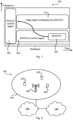
- Fig. 2 is a schematic diagram illustrating a communications network 100 where embodiments presented herein can be applied.
- the communications network 100 comprises a radio access network (as represented by its radio coverage area 120 in which a radio access network node 300 provides network access), a core network 130, and a service network 140.
- the radio access network is operatively connected to the core network 130 which in turn is operatively connected to the service network 140.
- the radio access network node 300 thereby enables wireless devices 200 to access services and exchange data as provided by the service network 140.
- wireless devices 200 include, but are not limited to, mobile stations, mobile phones, handsets, wireless local loop phones, user equipment (UE), smartphones, laptop computers, tablet computers, sensors, actuators, modems, repeaters, and network-equipped Internet of Things devices.
- radio access network nodes 110 include, but are not limited to, radio base stations, base transceiver stations, Node Bs, evolved Node Bs, gNB (in communications networks denoted "new radio" or NR for short), and access points.
- the communications system 100 may comprise a plurality of radio access network nodes 110, each providing network access to a plurality of wireless devices 200. The herein disclosed embodiments are not limited to any particular number of radio access network nodes 110 or wireless devices 200.
- codewords can be mapped to individual OFDM symbols, or even several codewords per OFDM symbol. It is noted that codewords and OFDM symbols are not necessarily exactly aligned, i.e., some codewords may span multiple OFDM symbols. This may enable the wireless device to start decoding as soon as an OFDM symbol comprising data has been received.
- the fifth generation of mobile telecommunications and wireless technology is not yet fully defined but in an advanced drafting stage within 3GPP. It includes work on 5G (NR) Access Technology. LTE terminology is used in this disclosure in a forward-looking sense, to include equivalent 5G entities or functionalities although a different term may be specified in 5G.
- NR 5G
- a general description of the agreements on 5GNew Radio (NR) Access Technology so far is contained in 3GPP TR 38.802 V0.3.0 (2016-10), of which a draft version has been published as R1-1610848. Final specifications may be published inter alia in the future 3GPP TS 38.2** series.
- the radio access network node may transmit and receive signals over a 100 MHz bandwidth and each wireless device may be limited to transmitting and receiving signals over a 40 MHz bandwidth.
- the embodiments disclosed herein therefore relate to mechanisms for monitoring search spaces and for enabling monitoring of search spaces.
- a wireless device 200 a method performed by the wireless device 200, a computer program product comprising code, for example in the form of a computer program, that when run on a wireless device 200, causes the wireless device 200 to perform the method.
- a radio access network node 300 a method performed by the radio access network node 300, a computer program product comprising code, for example in the form of a computer program, that when run on a radio access network node 300, causes the radio access network node 300 to perform the method.
- At least some of the embodiments disclosed herein relate to the transmission, reception, and usage of RSs of different types within an OFDM symbol in the downlink (i.e., as transmitted by the radio access network node and received by the wireless device).
- the embodiments may equally be applicable to an OFDM symbol transmitted in sidelink.
- the RSs may be used for demodulation of control channels that may be mapped to a control region.
- Figs. 3 and 4 are flowcharts illustrating embodiments as methods for monitoring search spaces. The methods are performed by the wireless device 200. The methods may advantageously be realized by executing computer programs 1320a.
- Fig. 3 illustrating a method for monitoring search spaces as performed by the wireless device 200 according to an embodiment.
- the wireless device 200 is configured to perform step S104: S104: The wireless device 200 receives an OFDM symbol in a downlink slot. At least part of the OFDM symbol is included in a device-specific search space and in a common search space.
- the wireless device 200 Upon having received the OFDM symbol the wireless device 200 monitors both a device-specific search space and a common search space and is thus configured to perform steps S106, S108: S106: The wireless device 200 monitors the device-specific search space for at least one device-specific reference signal.
- the wireless device 200 monitors the common search space for at least one non-device-specific reference signal.
- to monitor the search space for a reference signal is to be interpreted as: to read the search space attempting to recognize the reference signal, to search for the reference signal in the search space, to try to match the reference signal in the search space, to try to decode a control message transmitted in the search space knowing that the reference signal may be present, and/or to try to decode a control message transmitted in the search space assuming the possible presence of the reference signal.
- the method thus allows for transmission of both common and device-specific control messages (possibly beamformed differently) in the same OFDM symbol, enabling immediate decoding to start in the first OFDM symbol of any scheduled data region (common and/or device-specific).
- reference signals for data are preferably inserted in the beginning of the data region.
- the OFDM symbol is the first time-wise occurring OFDM symbol in the downlink slot.
- the OFDM symbol is initial in the downlink slot; with respect to time, the OFDM symbol was transmitted before the other symbols.
- Fig. 4 illustrating methods for monitoring search spaces as performed by the wireless device 200 according to further embodiments. It is assumed that steps S 104, S106, S108 are performed as in the above description with reference to Fig. 3 , which therefore need not be repeated.
- the wireless device may be made aware of the different control regions, location and type henceforth.
- the wireless device 200 is configured to perform step S102: S102: The wireless device obtains information regarding frequency location within the OFDM symbol of the device-specific search space and the common search space.
- This information may comprise respective control region location and size in the frequency domain.
- the location may be based on cell ID.
- the information may be device-specific.
- the frequency locations may be conveyed from the radio access network node 300 to the wireless device 200 by means of semi-static signaling over radio resource control (RRC) signaling, medium access control (MAC) element signaling, dynamic signaling in a previous PDCCH, or by other means.
- RRC radio resource control
- MAC medium access control
- the wireless device may obtain the time location of the OFDM symbol, e.g., in terms of the position of the symbol.
- Each search space, or control region may be defined as a set of subbands.
- each of the device-specific search space and the common search space is contained in a respective frequency subband.
- Each frequency subband may have a bandwidth in the order of 5 MHz. Different subbands may have different bandwidths.
- a common control subband and a device-specific control subband can thereby be used within (at least) one and the same OFDM symbol.
- a set of non-device-specific demodulation reference signals may be defined for the common subband or common search space, and a set of device-specific DMRS may be defined for the device-specific subband or device-specific search space.
- the device-specific search space comprises resources reserved for a device-specific DMRS
- the common search space comprises resources reserved for a non-device-specific DMRS.
- the remaining resource elements in the OFDM symbol that do not carry RSs may be used for control payload, such as common and/or device-specific PDCCH.
- each subband or search space may comprise resources reserved for multiple DMRSs. If a search space comprises multiple search space candidates, each candidate may be associated with its own DMRS resources. DMRS resources of different candidates may overlap or partially overlap, or may alternatively be disjoint.
- each search space may comprise one or several control channel candidates, such as PDCCH candidates, search space candidates, or search space control channel candidates. If a PDCCH is transmitted, it is transmitted on one of the search space PDCCH candidates. If a PDCCH is transmitted, then also a corresponding DMRS may be transmitted. Depending on which PDCCH is transmitted, there may be two combinations of PDCCH and DMRS simultaneously, otherwise only one. Alternatively, DMRS may be connected to a search space or a search space control channel candidate and transmitted independently of whether PDCCH is transmitted or not.
- the wireless device 200 is configured to perform steps S106a, S106b as part of step S 106:
- the wireless device 200 is configured to perform steps S108a, S 108b as part of step S108:
- resource elements not used for DMRS within a subband may be utilized for control purposes and/or data transmissions. Resource elements outside the control subbands may be used for data transmissions.
- the network via the radio access network node, may transmit a PDCCH addressed to multiple wireless devices 200 using a first beamforming setting, and may transmit a PDCCH addressed to a specific wireless device 200 using a second beamforming setting, different from the first beamforming setting.
- the first beamforming setting is relatively wide or at least wider than the second beamforming setting.
- a wide setting is one expected to have a low degree of spatial or angular selectivity; in line-of-sight conditions, this corresponds to a large beam angle. This allows the wireless device 200 to monitor the search space(s) in the control regions for both group messages and individual messages, decode these PDCCHs as early as is theoretically possible and start decoding data code words virtually immediately in the addressed data region.
- control regions might not occupy all resources in the OFDM symbol, and hence there may be resources left in the OFDM symbol that may be utilized for e.g. data traffic to at least one wireless device 200.
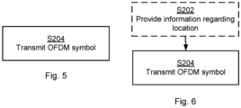
- Figs. 5 and 6 are flowcharts illustrating embodiments as methods for enabling monitoring of search spaces.
- the methods are performed by the radio access network node 300.
- the methods may advantageously be realized by executing computer programs 1320b.
- the radio access network node 300 transmits an OFDM symbol in downlink, but variations are equally possible where an OFDM symbol is transmitted in sidelink.
- Fig. 5 illustrating a method for enabling monitoring of search spaces as performed by the radio access network node 300 according to an embodiment.
- the wireless device 200 in a step S 104 receives an OFDM symbol in a downlink slot. It is assumed that the radio access network node 300 transmits such an OFDM symbol. Hence, the radio access network node 300 is configured to perform step S204.
- the radio access network node 300 transmits an OFDM symbol in a downlink slot. At least part of the OFDM symbol is included in a device-specific search space and a common search space.
- the device-specific search space comprises a device-specific reference signal
- the common search space comprises a non-device-specific reference signal.
- At least one of the search spaces comprises a RS if a physical control channel is transmitted in the downlink slot. If no physical control channel is transmitted, no RS is present.
- the device-specific reference signal enables a specific wireless device 200 or a specific group of wireless devices to monitor control messages.
- the non-device-specific reference signal enables non-specific wireless devices in a coverage area of the radio access network node 300 to monitor control messages.
- Fig. 6 illustrating methods for enabling monitoring of search spaces as performed by the radio access network node 300 according to further embodiments. It is assumed that step S204 is performed as described above with reference to Fig. 5 , so that this description need not be repeated.
- the wireless device 200 obtains location information.
- the radio access network node 300 is configured to perform step S202: S202: The radio access network node 300 provides information regarding frequency within the OFDM symbol of the device-specific search space and the common search space to a wireless device 200.
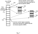
- Fig. 7 schematically illustrates an OFDM symbol structure 700 comprising both device-specific and non-device-specific control regions 710, 720.
- Respective control regions comprise resources for respective DMRS.
- Each control region comprises resource elements (RE) 740, 760 that are reserved for DMRS.
- REs 730, 750 may contain the PDCCH messages.
- the densities of the DMRS may be different in different control regions or may be uniform.
- the density and locations of respective DMRS may be configured or be in accordance with a fixed pattern, in dependence of the subband.
- the DMRS may be associated with individual search space PDCCH candidates and only be transmitted if a PDCCH is actually transmitted. If a DMRS is associated with an individual search space PDCCH candidate, DMRS resources of different candidates may overlap, partially overlap or may alternatively be disjoint.
- the radio access network node may be configured to only send a reference signal of a certain type if it also sends a PDCCH message of that type. In that way interference levels in the network may be controlled, or kept small.
- the reference signals may be located in the vicinity of the sent PDCCH message within the control region.
- Fig. 8 illustrates an OFDM symbol structure 800 comprising both device-specific and non-device-specific control regions (PDCCHs) 810, 820 identifying the location in time and/or frequency of data regions 830, 840. If the code words in one or both of the common or user-specific (or device-specific) region are arranged for decoding per OFDM symbol, latency may be reduced. In Fig. 8 the two types of control regions are non-overlapping, but they may alternatively be fully or partially overlapping.
- PDCCHs device-specific and non-device-specific control regions
- the device-specific search space and the common search space at least partially overlap.
- the common control region and the device-specific control region (partially) overlap, the respective reference signals must be distinguishable. There are several ways this may be ensured.
- the allocation may be that RSs (of a certain type) are only available when a PDCCH (of that type) is actually transmitted. Then preferably the RSs are transmitted only in the vicinity of the sent PDCCH. Since the radio access network node is aware of what it sends in a given resource, the radio access network node can ensure that different types of RSs are distinguishable.
- the wireless device 200 only has to monitor the overlapping search spaces using different assumptions concerning the RS type and concerning location of candidate message and RSs.
- RSs can be made distinguishable if they are transmitted in a non-overlapping fashion, in well enough isolated beams, or using orthogonal or quasi-orthogonal RS sequences. Different RS for the different search spaces may thus enable a device to distinguish between a control message transmitted in a common search space and in a device-specific search space, even if the control channel transmissions would use the same time-frequency resources.
- the device-specific search space and the common search space are separated (or disjoint). Hence, according to another embodiment the device-specific search space and the common search space do not overlap.
- An allocation scheme may be used to ensure that the device-specific RSs and the common RSs do not overlap.
- Device-specific RSs may have properties or characteristics which are dependent on the wireless device, a wireless device identity, a Cell Radio Network Temporary Identifier (CRNTI), wireless device capabilities, a configured parameter for the wireless device, or any other characteristic that may differentiate two or more wireless devices or may differentiate two or more groups of wireless devices.
- CRNTI Cell Radio Network Temporary Identifier
- Non-device-specific RSs may have properties or characteristics which are dependent on a cell ID, a location in the time or frequency domain, or a parameter configured for a set of wireless devices.
- a set of wireless devices in this sense may comprise those wireless devices which are to receive the PDCCH in the common search space; the set may in particular comprise all wireless devices in a cell.
- a control region may thus be monitored by means of so called search spaces, where a search space defines the possible locations of a control message.
- Properties of a search space may depend on a size of used control resources; for instance, in LTE the size is given by the aggregation level. If there are many possible aggregation levels/sizes of mapped control messages, there are many search spaces. This is true for both device-specific and common control regions.
- the embodiments disclosed herein are not dependent on, or limited to, the exact structure of the control regions or how they are to be monitored.
- search spaces may have a different number of subbands, possibly of different sizes. That is, although the embodiments and examples disclosed herein depict only one OFDM symbol comprising control messages, it is clear to the skilled person that there may be one or more than one OFDM symbol comprising control messages as long as at least one OFDM symbol comprises both device-specific and non-device-specific search spaces.
- Fig. 9 schematically illustrates, in terms of a number of functional units, the components of a wireless device 200 according to an embodiment.
- Processing circuitry 210 is provided using any combination of one or more of a suitable central processing unit (CPU), multiprocessor, microcontroller, digital signal processor (DSP), etc., capable of executing software instructions stored in a computer program product 13 10a (as in Fig. 13 ), e.g. in the form of a storage medium 230.
- the processing circuitry 210 may further be provided as at least one application-specific integrated circuit (ASIC), or field programmable gate array (FPGA).
- ASIC application-specific integrated circuit
- FPGA field programmable gate array
- the processing circuitry 210 is configured to cause the wireless device 200 to perform a set of operations, or steps, S102-S108, as disclosed above.
- the storage medium 230 may store the set of operations
- the processing circuitry 210 may be configured to retrieve the set of operations from the storage medium 230 to cause the wireless device 200 to perform the set of operations.
- the set of operations may be provided as a set of executable instructions.
- the processing circuitry 210 is thereby arranged to execute methods as herein disclosed.
- the storage medium 230 may also comprise persistent storage, which, for example, can be any single one or combination of magnetic memory, optical memory, solid state memory or even remotely mounted memory.
- the wireless device 200 may further comprise a communications interface 220 at least configured for communications with a radio access network node. As such the communications interface 220 may comprise one or more transmitters and receivers, comprising analogue and digital components.
- the processing circuitry 210 controls the general operation of the wireless device 200 e.g. by sending data and control signals to the communications interface 220 and the storage medium 230, by receiving data and reports from the communications interface 220, and by retrieving data and instructions from the storage medium 230.
- Other components, as well as the related functionality, of the wireless device 200 are omitted in order not to obscure the concepts presented herein.
- Fig. 10 schematically illustrates, in terms of a number of functional modules, the components of a wireless device 200 according to an embodiment.
- the wireless device 200 of Fig. 10 comprises a number of functional modules; a receive module 210b configured to perform step S104, a monitor module 210c configured to perform step S 106, and a monitor module 210f configured to perform step S108.
- the wireless device 200 of Fig. 10 comprises a number of functional modules; a receive module 210b configured to perform step S104, a monitor module 210c configured to perform step S 106, and a monitor module 210f configured to perform step S108.
- 10 may further comprise a number of optional functional modules, such as any of an obtain module 210a configured to perform step S 102, a detect module 210d configured to perform step S 106a, an identify module 210e configured to perform step S 106b, a detect module 210g configured to perform step S 108a, and an identify module 210h configured to perform step S108b.
- optional functional modules such as any of an obtain module 210a configured to perform step S 102, a detect module 210d configured to perform step S 106a, an identify module 210e configured to perform step S 106b, a detect module 210g configured to perform step S 108a, and an identify module 210h configured to perform step S108b.
- each functional module 210a-210h may in one embodiment be implemented only in hardware or and in another embodiment with the help of software, i.e., the latter embodiment having computer program instructions stored on the storage medium 230 which when run on the processing circuitry makes the wireless device 200 perform the corresponding steps mentioned above in conjunction with Fig 10 .
- the modules correspond to parts of a computer program, they do not need to be separate modules therein, but the way in which they are implemented in software is dependent on the programming language used.
- one or more or all functional modules 210a-210h may be implemented by the processing circuitry 210, possibly in cooperation with the communications interface 220 and/or the storage medium 230.
- the processing circuitry 210 may thus be configured to from the storage medium 230 fetch instructions as provided by a functional module 210a-210h and to execute these instructions, thereby performing any steps as disclosed herein.
- Fig. 11 schematically illustrates, in terms of a number of functional units, the components of a radio access network node 300 according to an embodiment.
- Processing circuitry 310 is provided using any combination of one or more of a suitable central processing unit (CPU), multiprocessor, microcontroller, digital signal processor (DSP), etc., capable of executing software instructions stored in a computer program product 1310b (as in Fig. 13 ), e.g. in the form of a storage medium 330.
- the processing circuitry 310 may further be provided as at least one application-specific integrated circuit (ASIC), or field programmable gate array (FPGA).
- ASIC application-specific integrated circuit
- FPGA field programmable gate array
- the processing circuitry 310 is configured to cause the radio access network node 300 to perform a set of operations, or steps, S202-S204, as disclosed above.
- the storage medium 330 may store the set of operations
- the processing circuitry 310 may be configured to retrieve the set of operations from the storage medium 330 to cause the radio access network node 300 to perform the set of operations.
- the set of operations may be provided as a set of executable instructions.
- the processing circuitry 310 is thereby arranged to execute methods as herein disclosed.
- the storage medium 330 may also comprise persistent storage, which, for example, can be any single one or combination of magnetic memory, optical memory, solid state memory or even remotely mounted memory.
- the radio access network node 300 may further comprise a communications interface 320 for communications with other entities and devices of the communications network 100 and the wireless device 200.
- the communications interface 320 may comprise one or more transmitters and receivers, comprising analog and digital components.
- the processing circuitry 310 controls the general operation of the radio access network node 300 e.g. by sending data and control signals to the communications interface 320 and the storage medium 330, by receiving data and reports from the communications interface 320, and by retrieving data and instructions from the storage medium 330.
- Other components, as well as the related functionality, of the radio access network node 300 are omitted in order not to obscure the concepts presented herein.
- Fig. 12 schematically illustrates, in terms of a number of functional modules, the components of a radio access network node 300 according to an embodiment.
- the radio access network node 300 of Fig. 12 comprises a transmit module 310b configured to perform step S204.
- the radio access network node 300 of Fig. 12 may further comprise a number of optional functional modules, such as a provide module 3 10a configured to perform step S202.
- each functional module 310a-310b may be implemented in hardware or in software.
- one or more or all functional modules 310a-310b may be implemented by the processing circuitry 310, possibly in cooperation with the communications interface 320 and/or the storage medium 330.
- the processing circuitry 310 may thus be arranged to from the storage medium 330 fetch instructions as provided by a functional module 3 10a-3 10b and to execute these instructions, thereby performing any steps of the radio access network node 300 as disclosed herein.
- Fig. 13 shows one example of a computer program product 1310a, 1310b comprising computer readable means 1330.
- a computer program 1320a can be stored, which computer program 1320a can cause the processing circuitry 210 and thereto operatively coupled entities and devices, such as the communications interface 220 and the storage medium 230, to execute methods according to embodiments described herein.
- the computer program 1320a and/or computer program product 1310a may thus provide means for performing any steps of the wireless device 200 as herein disclosed.
- a computer program 1320b can be stored, which computer program 1320b can cause the processing circuitry 310 and thereto operatively coupled entities and devices, such as the communications interface 320 and the storage medium 330, to execute methods according to embodiments described herein.
- the computer program 1320b and/or computer program product 1310b may thus provide means for performing any steps of the radio access network node 300 as herein disclosed.
- the computer program product 1310a, 1310b is illustrated as an optical disc, such as a CD (compact disc) or a DVD (digital versatile disc) or a Blu-Ray disc.
- the computer program product 1310a, 1310b could also be embodied as a memory, such as a random access memory (RAM), a read-only memory (ROM), an erasable programmable read-only memory (EPROM), or an electrically erasable programmable read-only memory (EEPROM) and more particularly as a non-volatile storage medium of a device in an external memory such as a USB (Universal Serial Bus) memory or a Flash memory, such as a compact Flash memory.
- RAM random access memory
- ROM read-only memory
- EPROM erasable programmable read-only memory
- EEPROM electrically erasable programmable read-only memory
- the computer program 1320a, 1320b is here schematically shown as a track on the depicted optical disk, the computer program 1320a,
Landscapes
- Engineering & Computer Science (AREA)
- Signal Processing (AREA)
- Computer Networks & Wireless Communication (AREA)
- Computer Security & Cryptography (AREA)
- Mobile Radio Communication Systems (AREA)
- Monitoring And Testing Of Transmission In General (AREA)
Claims (15)
- Verfahren zum Überwachen von Suchräumen, wobei das Verfahren von einer drahtlosen Vorrichtung (200) durchgeführt wird, wobei das Verfahren Folgendes umfasst:Empfangen (S104) eines orthogonalen Frequenzmultiplexsymbols, OFDM-Symbols, wobei das OFDM-Symbol zumindest teilweise in einem vorrichtungsspezifischen Suchraum der drahtlosen Vorrichtung enthalten ist und zumindest teilweise in einem von der drahtlosen Vorrichtung verwendeten gemeinsamen Suchraum enthalten ist;Überwachen (S106) des vorrichtungsspezifischen Suchraums auf mindestens ein vorrichtungsspezifisches Demodulationsreferenzsignal, DM-RS, das in dem OFDM-Symbol bereitgestellt ist; undÜberwachen (S108) des gemeinsamen Suchraums auf mindestens ein nicht-vorrichtungsspezifisches Demodulationsreferenzsignal, DM-RS, das in demselben OFDM-Symbol bereitgestellt ist; wobei der vorrichtungsspezifische Suchraum und der gemeinsame Suchraum in einem ersten bzw. einem zweiten Teilband aufgenommen sind, undStarten von Datendekodierung in dem ersten OFDM-Symbol eines geplanten Datenbereichs, wobei das erste Teilband und das zweite Teilband unterschiedliche Bandbreiten aufweisen.
- Verfahren nach Anspruch 1, ferner umfassend:Erfassen (S106a) einer vorrichtungsspezifischen physikalischen Downlink-Steuerkanalnachricht, PDCCH-Nachricht, in dem vorrichtungsspezifischen Suchraum; undIdentifizieren (S106b), aus der vorrichtungsspezifischen PDCCH-Nachricht, von Ressourcenblöcken für einen vorrichtungsspezifischen Datenbereich.
- Verfahren nach Anspruch 1 oder 2, ferner umfassend:Erfassen (S108a) einer nicht-vorrichtungsspezifischen physikalischen Downlink-Steuerkanalnachricht, PDCCH-Nachricht in dem gemeinsamen Suchraum;Identifizieren (S108b), aus der nicht-vorrichtungsspezifischen PDCCH-Nachricht, von Ressourcenblöcken für einen nicht-vorrichtungsspezifischen Datenbereich.
- Verfahren nach einem der vorstehenden Ansprüche, wobei das OFDM-Symbol ein anfängliches OFDM-Symbol in dem Downlink-Schlitz ist.
- Verfahren nach einem der vorstehenden Ansprüche, wobei der vorrichtungsspezifische Suchraum Zeit-Frequenz-Ressourcen umfasst, die für das vorrichtungsspezifische Demodulationsreferenzsignal, DM-RS, reserviert sind, und wobei der gemeinsame Suchraum Zeit-Frequenz-Ressourcen umfasst, die für das nicht-vorrichtungsspezifische DM-RS reserviert sind.
- Verfahren nach einem der vorstehenden Ansprüche, wobei das vorrichtungsspezifische DMRS von mindestens einem Parameter der drahtlosen Vorrichtung (200) abhängt, wie z. B. einer drahtlosen Vorrichtungsidentität.
- Verfahren nach einem der vorstehenden Ansprüche, ferner umfassend:
Erhalten (S102) von Informationen bezüglich einer Frequenzposition innerhalb des OFDM-Symbols des vorrichtungsspezifischen Suchraums und des gemeinsamen Suchraums. - Drahtlose Vorrichtung (200) zum Überwachen von Suchräumen, wobei die drahtlose Vorrichtung (200) eine Verarbeitungsschaltung (210) und eine Kommunikationsschnittstelle (220) umfasst, wobei die Verarbeitungsschaltung dazu konfiguriert ist, die drahtlose Vorrichtung (200) zu Folgendem zu veranlassen:Empfangen eines orthogonalen Frequenzmultiplexsymbols, OFDM-Symbols, unter Verwendung der Kommunikationsschnittstelle (220), wobei das OFDM-Symbol zumindest teilweise in einem vorrichtungsspezifischen Suchraum der drahtlosen Vorrichtung enthalten ist und zumindest teilweise in einem von der drahtlosen Vorrichtung verwendeten gemeinsamen Suchraum enthalten ist;Überwachen des vorrichtungsspezifischen Suchraums auf mindestens ein vorrichtungsspezifisches Demodulationsreferenzsignal, DM-RS, das in dem OFDM-Symbol bereitgestellt ist; undÜberwachen des gemeinsamen Suchraums auf mindestens ein nicht-vorrichtungsspezifisches Demodulationsreferenzsignal, DM-RS, das in demselben OFDM-Symbol bereitgestellt ist; wobei der vorrichtungsspezifische Suchraum und der gemeinsame Suchraum in einem ersten bzw. einem zweiten Teilband aufgenommen sind, undStarten von Datendekodierung in dem ersten OFDM-Symbol eines geplanten Datenbereichs, wobei das erste Teilband und das zweite Teilband unterschiedliche Bandbreiten aufweisen.
- Verfahren zum Ermöglichen des Überwachens von Suchräumen, wobei das Verfahren von einem Funkzugangsnetzknoten (300) durchgeführt wird, wobei das Verfahren Folgendes umfasst:Übertragen (S204) eines orthogonalen Frequenzmultiplexsymbols, OFDM-Symbols, wobei das OFDM-Symbol zumindest teilweise in einem vorrichtungsspezifischen Suchraum der drahtlosen Vorrichtung enthalten ist und zumindest teilweise in einem von der drahtlosen Vorrichtung verwendeten gemeinsamen Suchraum enthalten ist,wobei der vorrichtungsspezifische Suchraum ein vorrichtungsspezifisches Demodulationsreferenzsignal, DM-RS, umfasst, das in dem OFDM-Symbol bereitgestellt ist, und der gemeinsame Suchraum ein nicht-vorrichtungsspezifisches Demodulationsreferenzsignal, DM-RS, umfasst, das in demselben OFDM-Symbol bereitgestellt ist;wobei der vorrichtungsspezifische Suchraum und der gemeinsame Suchraum in einem von der drahtlosen Vorrichtung verwendeten ersten bzw. zweiten Teilband aufgenommen sind, wobei das erste Teilband und das zweite Teilband unterschiedliche Bandbreiten aufweisen, undÜbertragen von Daten an die drahtlose Vorrichtung in einem geplanten Datenbereich.
- Verfahren nach Anspruch 9, wobei das vorrichtungsspezifische DM-RS eine bestimmte drahtlose Vorrichtung (200) oder eine bestimmte Gruppe von drahtlosen Vorrichtungen dazu befähigt, Kontrollnachrichten zu überwachen.
- Verfahren nach Anspruch 9 oder 10, wobei das nicht-vorrichtungsspezifische DM-RS nicht-vorrichtungsspezifische drahtlose Vorrichtungen in einem Versorgungsbereich des Funkzugangsnetzknotens (300) dazu befähigt, Kontrollnachrichten zu überwachen.
- Verfahren nach einem der Ansprüche 9 bis 11, ferner umfassend:
Bereitstellen (S202) von Informationen bezüglich einer Frequenzposition innerhalb des OFDM-Symbols des vorrichtungsspezifischen Suchraums und des gemeinsamen Suchraums für eine drahtlose Vorrichtung (200). - Verfahren nach einem der Ansprüche 9 bis 12, wobei das vorrichtungsspezifische DM-RS von mindestens einem Parameter der drahtlosen Vorrichtung (200) abhängt, wie z. B. einer drahtlosen Vorrichtungsidentität.
- Funkzugangsnetzknoten (300) zum Ermöglichen des Überwachens von Suchräumen, wobei der Funkzugangsnetzknoten (300) eine Verarbeitungsschaltung (310) und eine Kommunikationsschnittstelle (320) umfasst, wobei die Verarbeitungsschaltung dazu konfiguriert ist, den Funkzugangsnetzknoten (300) zu Folgendem zu veranlassen:Übertragen eines orthogonalen Frequenzmultiplexsymbols, OFDM-Symbols, unter Verwendung der Kommunikationsschnittstelle (320), wobei das OFDM-Symbol zumindest teilweise in einem vorrichtungsspezifischen Suchraum der drahtlosen Vorrichtung enthalten ist und zumindest teilweise in einem von der drahtlosen Vorrichtung verwendeten gemeinsamen Suchraum enthalten ist;wobei der vorrichtungsspezifische Suchraum ein vorrichtungsspezifisches Demodulationsreferenzsignal, DM-RS, umfasst, das in dem OFDM-Symbol bereitgestellt ist, und der gemeinsame Suchraum ein nicht-vorrichtungsspezifisches Demodulationsreferenzsignal, DM-RS, umfasst, das in demselben OFDM-Symbol bereitgestellt ist; wobei der vorrichtungsspezifische Suchraum und der gemeinsame Suchraum in einem von der drahtlosen Vorrichtung verwendeten ersten bzw. zweiten Teilband aufgenommen sind, wobei das erste Teilband und das zweite Teilband unterschiedliche Bandbreiten aufweisen, undÜbertragen von Daten an die drahtlose Vorrichtung in einem geplanten Datenbereich.
- Computerprogramm (1320) zum Ermöglichen des Überwachens von Suchräumen, wobei das Computerprogramm Folgendes umfasst:Computercode, der beim Ausführen auf einer Verarbeitungsschaltung (210) einer drahtlosen Vorrichtung (200) die drahtlose Vorrichtung (200) dazu veranlasst, das Verfahren nach einem der Ansprüche 1 bis 7 durchzuführen; oderComputercode, der beim Ausführen auf einer Verarbeitungsschaltung (310) eines Funkzugangsnetzknotens (300) den Funkzugangsnetzknoten (300) dazu veranlasst, das Verfahren nach einem der Ansprüche 9 bis 13 durchzuführen.
Priority Applications (4)
| Application Number | Priority Date | Filing Date | Title |
|---|---|---|---|
| EP25191231.7A EP4633078A3 (de) | 2016-11-02 | 2016-11-02 | Suchraumüberwachung |
| EP24190229.5A EP4425817B1 (de) | 2016-11-02 | 2016-11-02 | Suchraumüberwachung |
| EP23182013.5A EP4258587B1 (de) | 2016-11-02 | 2016-11-02 | Suchraumüberwachung |
| ES23182013T ES2987263T3 (es) | 2016-11-02 | 2016-11-02 | Monitorización del espacio de búsqueda |
Applications Claiming Priority (5)
| Application Number | Priority Date | Filing Date | Title |
|---|---|---|---|
| EP19167339.1A EP3562086B1 (de) | 2016-11-02 | 2016-11-02 | Suchbereichsüberwachung in drahtlosen kommunikationssystemen |
| EP16795455.1A EP3363139B1 (de) | 2016-11-02 | 2016-11-02 | Suchbereichsüberwachung in drahtlosen kommunikationsnetzwerken |
| PCT/SE2016/051077 WO2018084755A1 (en) | 2016-11-02 | 2016-11-02 | Search space monitoring in wireless communication networks |
| EP23182013.5A EP4258587B1 (de) | 2016-11-02 | 2016-11-02 | Suchraumüberwachung |
| EP21175135.9A EP3917059B1 (de) | 2016-11-02 | 2016-11-02 | Suchraumüberwachung |
Related Parent Applications (4)
| Application Number | Title | Priority Date | Filing Date |
|---|---|---|---|
| EP16795455.1A Division EP3363139B1 (de) | 2016-11-02 | 2016-11-02 | Suchbereichsüberwachung in drahtlosen kommunikationsnetzwerken |
| EP19167339.1A Division EP3562086B1 (de) | 2016-11-02 | 2016-11-02 | Suchbereichsüberwachung in drahtlosen kommunikationssystemen |
| EP21175135.9A Division-Into EP3917059B1 (de) | 2016-11-02 | 2016-11-02 | Suchraumüberwachung |
| EP21175135.9A Division EP3917059B1 (de) | 2016-11-02 | 2016-11-02 | Suchraumüberwachung |
Related Child Applications (2)
| Application Number | Title | Priority Date | Filing Date |
|---|---|---|---|
| EP25191231.7A Division EP4633078A3 (de) | 2016-11-02 | 2016-11-02 | Suchraumüberwachung |
| EP24190229.5A Division EP4425817B1 (de) | 2016-11-02 | 2016-11-02 | Suchraumüberwachung |
Publications (4)
| Publication Number | Publication Date |
|---|---|
| EP4258587A2 EP4258587A2 (de) | 2023-10-11 |
| EP4258587A3 EP4258587A3 (de) | 2023-11-01 |
| EP4258587B1 true EP4258587B1 (de) | 2024-07-31 |
| EP4258587C0 EP4258587C0 (de) | 2024-07-31 |
Family
ID=57321391
Family Applications (6)
| Application Number | Title | Priority Date | Filing Date |
|---|---|---|---|
| EP16795455.1A Active EP3363139B1 (de) | 2016-11-02 | 2016-11-02 | Suchbereichsüberwachung in drahtlosen kommunikationsnetzwerken |
| EP21175135.9A Active EP3917059B1 (de) | 2016-11-02 | 2016-11-02 | Suchraumüberwachung |
| EP23182013.5A Active EP4258587B1 (de) | 2016-11-02 | 2016-11-02 | Suchraumüberwachung |
| EP25191231.7A Pending EP4633078A3 (de) | 2016-11-02 | 2016-11-02 | Suchraumüberwachung |
| EP24190229.5A Active EP4425817B1 (de) | 2016-11-02 | 2016-11-02 | Suchraumüberwachung |
| EP19167339.1A Active EP3562086B1 (de) | 2016-11-02 | 2016-11-02 | Suchbereichsüberwachung in drahtlosen kommunikationssystemen |
Family Applications Before (2)
| Application Number | Title | Priority Date | Filing Date |
|---|---|---|---|
| EP16795455.1A Active EP3363139B1 (de) | 2016-11-02 | 2016-11-02 | Suchbereichsüberwachung in drahtlosen kommunikationsnetzwerken |
| EP21175135.9A Active EP3917059B1 (de) | 2016-11-02 | 2016-11-02 | Suchraumüberwachung |
Family Applications After (3)
| Application Number | Title | Priority Date | Filing Date |
|---|---|---|---|
| EP25191231.7A Pending EP4633078A3 (de) | 2016-11-02 | 2016-11-02 | Suchraumüberwachung |
| EP24190229.5A Active EP4425817B1 (de) | 2016-11-02 | 2016-11-02 | Suchraumüberwachung |
| EP19167339.1A Active EP3562086B1 (de) | 2016-11-02 | 2016-11-02 | Suchbereichsüberwachung in drahtlosen kommunikationssystemen |
Country Status (20)
| Country | Link |
|---|---|
| US (6) | US10397854B2 (de) |
| EP (6) | EP3363139B1 (de) |
| JP (1) | JP6665351B2 (de) |
| KR (3) | KR102225606B1 (de) |
| CN (2) | CN112929146B (de) |
| AU (1) | AU2016428856B2 (de) |
| BR (1) | BR112018075136B1 (de) |
| CA (1) | CA3039170C (de) |
| CO (1) | CO2019003461A2 (de) |
| DK (1) | DK3363139T3 (de) |
| ES (5) | ES2890704T3 (de) |
| HU (1) | HUE043736T2 (de) |
| IL (1) | IL263566B (de) |
| MX (1) | MX376682B (de) |
| MY (1) | MY196521A (de) |
| PL (2) | PL3562086T3 (de) |
| RU (1) | RU2708227C1 (de) |
| TW (1) | TWI713337B (de) |
| WO (1) | WO2018084755A1 (de) |
| ZA (1) | ZA201808435B (de) |
Families Citing this family (14)
| Publication number | Priority date | Publication date | Assignee | Title |
|---|---|---|---|---|
| JP6665351B2 (ja) * | 2016-11-02 | 2020-03-13 | テレフオンアクチーボラゲット エルエム エリクソン(パブル) | 無線通信ネットワークにおけるサーチスペースの監視 |
| US11601870B2 (en) * | 2016-12-14 | 2023-03-07 | Ntt Docomo, Inc. | Terminal, radio communication method and base station to monitor search spaces |
| US11601820B2 (en) * | 2017-01-27 | 2023-03-07 | Qualcomm Incorporated | Broadcast control channel for shared spectrum |
| WO2018151533A1 (ko) | 2017-02-14 | 2018-08-23 | 엘지전자 주식회사 | 무선 통신 시스템에서, 데이터를 송수신하는 방법 및 이를 위한 장치 |
| US10897753B2 (en) * | 2017-05-04 | 2021-01-19 | Sharp Kabushiki Kaisha | Systems and methods for supporting multiple allocations in UL/DL grant for a 5G NR UE and gNB |
| PL3533259T3 (pl) | 2017-10-10 | 2020-07-13 | Telefonaktiebolaget Lm Ericsson (Publ) | Raportowanie wskaźnika NSA/SA NR |
| US11102736B2 (en) | 2017-10-24 | 2021-08-24 | Qualcomm Incorporated | Channel and synchronization raster |
| CN118473619A (zh) * | 2018-09-28 | 2024-08-09 | 索尼集团公司 | 发现信令的方法、相关网络节点和相关无线电子设备 |
| US12212987B2 (en) | 2019-10-04 | 2025-01-28 | Telefonaktiebolaget Lm Ericsson (Publ) | Switching a configuration of a search space set used for control channel monitoring |
| US11659423B2 (en) * | 2020-07-10 | 2023-05-23 | Qualcomm Incorporated | Indications of physical downlink control channel monitoring occasion aggregation via demodulation reference signal parameters |
| KR102514448B1 (ko) | 2021-01-18 | 2023-03-29 | 엘지전자 주식회사 | 무선 통신 시스템에서 무선 신호 송수신 방법 및 장치 |
| US11546111B2 (en) | 2021-06-24 | 2023-01-03 | Ultralogic 6G, Llc | Demarking the start and end of 5G/6G downlink messages |
| US11438122B2 (en) | 2021-06-14 | 2022-09-06 | Ultralogic 6G, Llc | Custom downlink search-spaces for low-complexity 5G/6G messaging |
| WO2023182802A1 (ko) * | 2022-03-23 | 2023-09-28 | 주식회사 케이티 | 무선 통신 시스템에서 nr(new radio technology) pdcch(physical downlink control channel)를 전송 및 수신하는 방법 및 장치 |
Family Cites Families (46)
| Publication number | Priority date | Publication date | Assignee | Title |
|---|---|---|---|---|
| US8009661B2 (en) * | 2007-01-31 | 2011-08-30 | Telefonaktiebolaget Lm Ericsson (Publ) | Cell searching system and method |
| MX2010004489A (es) * | 2007-10-29 | 2010-05-05 | Panasonic Corp | Aparato de estacion de base de comunicacion inalambrica, aparato de estacion movil de comunicacion inalambrica y metodo de distribucion de canal de control. |
| CN104901778B (zh) * | 2009-12-17 | 2018-07-24 | Lg电子株式会社 | 无线通信系统中的接收和发送方法及设备 |
| EP3534563B1 (de) * | 2010-02-11 | 2025-04-09 | Huawei Technologies Co., Ltd. | Verfahren, basisstation, benutzergerät und system zum senden und empfangen von pdcch-signalisierung |
| CN101827444B (zh) * | 2010-03-31 | 2015-03-25 | 中兴通讯股份有限公司 | 一种测量参考信号的信令配置系统及方法 |
| US9276722B2 (en) * | 2010-05-05 | 2016-03-01 | Qualcomm Incorporated | Expanded search space for R-PDCCH in LTE-A |
| US9380567B2 (en) * | 2010-08-16 | 2016-06-28 | Qualcomm Incorporated | Search space design for relay physical downlink control channel (R-PDCCH) |
| WO2012118270A1 (ko) * | 2011-03-01 | 2012-09-07 | 엘지전자 주식회사 | 다중 노드 시스템에서 단말의 제어 정보 검색 방법 및 장치 |
| US9848415B2 (en) * | 2011-07-06 | 2017-12-19 | Nokia Solutions And Networks Oy | DM RD based LTE downlink physical layer |
| WO2013015632A2 (ko) * | 2011-07-26 | 2013-01-31 | 엘지전자 주식회사 | 무선 통신 시스템에서 제어 정보의 전송 방법 및 장치 |
| CN102904669B (zh) * | 2011-07-29 | 2016-05-18 | 上海贝尔股份有限公司 | 预编码物理下行控制信道参考信号及盲译码方法和装置 |
| US9252918B2 (en) * | 2011-08-15 | 2016-02-02 | Google Technology Holdings LLC | Method and apparatus for control channel transmission and reception |
| US9197387B2 (en) * | 2011-08-15 | 2015-11-24 | Google Technology Holdings LLC | Method and apparatus for control channel transmission and reception |
| EP2779556A4 (de) * | 2011-11-01 | 2015-08-05 | Lg Electronics Inc | Verfahren und drahtlose vorrichtung zur überwachung von steuerkanälen |
| JP5856810B2 (ja) * | 2011-11-02 | 2016-02-10 | シャープ株式会社 | 基地局装置、移動局装置、無線通信方法、無線通信システムおよび集積回路 |
| US9338774B2 (en) * | 2011-11-04 | 2016-05-10 | Lg Electronics Inc. | Method and apparatus for user equipment searching control channel in wireless communication system |
| CN103947144B (zh) * | 2011-11-23 | 2017-03-08 | Lg电子株式会社 | 在无线通信系统中发送/获得控制信息的方法和设备 |
| CN104081709B (zh) * | 2012-01-27 | 2017-09-08 | 交互数字专利控股公司 | 用于在基于多载波和/或准校准网络中提供ePDCCH的装置和/或方法 |
| KR20140128385A (ko) * | 2012-01-30 | 2014-11-05 | 알까뗄 루슨트 | 모바일 송수신기를 위한 장치, 방법, 및 컴퓨터 프로그램과 기지국 송수신기를 위한 장치, 방법, 및 컴퓨터 프로그램 |
| WO2013129870A1 (ko) * | 2012-03-01 | 2013-09-06 | 엘지전자 주식회사 | 무선 통신 시스템에서 하향링크 제어 채널을 검출하기 위한 검색 영역을 설정하는 방법 및 이를 위한 장치 |
| US8737251B2 (en) * | 2012-03-19 | 2014-05-27 | Alcatel Lucent | Method and apparatus for search space configuration for enhanced physical downlink control channel |
| US8971881B2 (en) * | 2012-03-23 | 2015-03-03 | Google Technology Holdings LLC | Radio link monitoring in a wireless communication device for an enhanced control channel |
| US8995366B2 (en) * | 2012-03-23 | 2015-03-31 | Google Technology Holdings LLC | Radio link monitoring in a wireless communication device for a enhanced control channel |
| US9497756B2 (en) * | 2012-03-25 | 2016-11-15 | Comcast Cable Communications, Llc | Base station radio resource management |
| US9338773B2 (en) * | 2012-03-26 | 2016-05-10 | Qualcomm Incorporated | Common search space for EPDCCH in LTE |
| GB2501917A (en) * | 2012-05-10 | 2013-11-13 | Nec Corp | Communication system |
| JP2013243460A (ja) * | 2012-05-18 | 2013-12-05 | Sharp Corp | 端末、基地局、通信システムおよび通信方法 |
| US8761109B2 (en) * | 2012-08-03 | 2014-06-24 | Motorola Mobility Llc | Method and apparatus for receiving a control channel |
| ES2747783T3 (es) * | 2012-11-01 | 2020-03-11 | Huawei Tech Co Ltd | Procedimiento y aparato para determinar un espacio de búsqueda de canal de control |
| CN110266453B (zh) * | 2012-11-09 | 2023-11-28 | 北京三星通信技术研究有限公司 | 盲检公共搜索空间和ue特定搜索空间的方法及设备 |
| US9386576B2 (en) * | 2012-11-14 | 2016-07-05 | Qualcomm Incorporated | PUCCH resource determination for EPDCCH |
| EP3709730A1 (de) * | 2013-01-16 | 2020-09-16 | Interdigital Patent Holdings, Inc. | Erkennungssignalerzeugung und -empfang |
| EP2975895A1 (de) * | 2013-03-13 | 2016-01-20 | Sharp Kabushiki Kaisha | Basisstation, endgerät, kommunikationssystem, kommunikationsverfahren und integrierte schaltung |
| US11283574B2 (en) * | 2013-04-03 | 2022-03-22 | Interdigital Patent Holdings, Inc. | EPDCCH common search space design for one or more carrier types |
| WO2014181836A1 (ja) * | 2013-05-09 | 2014-11-13 | シャープ株式会社 | 端末装置、通信方法および集積回路 |
| US20160242203A1 (en) * | 2013-11-22 | 2016-08-18 | Lg Electronics Inc. | Method for receiving bundle of pdcch, and mtc device |
| WO2016018469A1 (en) * | 2014-08-01 | 2016-02-04 | Intel IP Corporation | Pdcch design for narrowband deployment |
| US10218482B2 (en) * | 2014-08-28 | 2019-02-26 | Telefonaktiebolaget Lm Ericsson (Publ) | Network node and method for managing transmission of cell reference symbols |
| JP6476306B2 (ja) * | 2015-01-29 | 2019-02-27 | テレフオンアクチーボラゲット エルエム エリクソン(パブル) | Mtcデバイスに適したpdcchの初期化 |
| KR20180004120A (ko) | 2015-04-08 | 2018-01-10 | 인터디지탈 패튼 홀딩스, 인크 | 감소된 출력 및 커버리지 향상을 가지는 무선 송수신 유닛(wtru)용 멀티서브대역 기반 전송 방법 및 장치 |
| US10122558B2 (en) * | 2015-04-10 | 2018-11-06 | Motorola Mobility Llc | Method and apparatus for reception of control signaling |
| WO2017148498A1 (en) * | 2016-02-29 | 2017-09-08 | Telefonaktiebolaget Lm Ericsson (Publ) | Timing requirement dependent search space configuration for mtc devices of different categories |
| EP3455985B1 (de) * | 2016-05-11 | 2022-03-09 | Convida Wireless, LLC | Neuer funk-downlink-steuerkanal |
| BR112018073215A2 (pt) * | 2016-05-13 | 2019-02-19 | Huawei Technologies Co., Ltd. | método de envio de informações de controle de enlace descendente, método de detecção de informações de controle de enlace descendente, e dispositivo |
| US11277223B2 (en) * | 2016-05-20 | 2022-03-15 | Apple Inc. | Control channel design for category-A devices |
| JP6665351B2 (ja) | 2016-11-02 | 2020-03-13 | テレフオンアクチーボラゲット エルエム エリクソン(パブル) | 無線通信ネットワークにおけるサーチスペースの監視 |
-
2016
- 2016-11-02 JP JP2019523072A patent/JP6665351B2/ja active Active
- 2016-11-02 CN CN202110226897.XA patent/CN112929146B/zh active Active
- 2016-11-02 RU RU2019106720A patent/RU2708227C1/ru active
- 2016-11-02 EP EP16795455.1A patent/EP3363139B1/de active Active
- 2016-11-02 EP EP21175135.9A patent/EP3917059B1/de active Active
- 2016-11-02 KR KR1020197002052A patent/KR102225606B1/ko active Active
- 2016-11-02 DK DK16795455.1T patent/DK3363139T3/da active
- 2016-11-02 EP EP23182013.5A patent/EP4258587B1/de active Active
- 2016-11-02 WO PCT/SE2016/051077 patent/WO2018084755A1/en not_active Ceased
- 2016-11-02 MX MX2018015010A patent/MX376682B/es active IP Right Grant
- 2016-11-02 MY MYPI2018002808A patent/MY196521A/en unknown
- 2016-11-02 HU HUE16795455A patent/HUE043736T2/hu unknown
- 2016-11-02 KR KR1020227016223A patent/KR20220066995A/ko not_active Ceased
- 2016-11-02 CN CN201680088201.9A patent/CN109565384B/zh active Active
- 2016-11-02 ES ES19167339T patent/ES2890704T3/es active Active
- 2016-11-02 ES ES21175135T patent/ES2962303T3/es active Active
- 2016-11-02 ES ES23182013T patent/ES2987263T3/es active Active
- 2016-11-02 US US15/500,700 patent/US10397854B2/en active Active
- 2016-11-02 EP EP25191231.7A patent/EP4633078A3/de active Pending
- 2016-11-02 PL PL19167339T patent/PL3562086T3/pl unknown
- 2016-11-02 ES ES24190229T patent/ES3045972T3/es active Active
- 2016-11-02 EP EP24190229.5A patent/EP4425817B1/de active Active
- 2016-11-02 AU AU2016428856A patent/AU2016428856B2/en active Active
- 2016-11-02 BR BR112018075136-7A patent/BR112018075136B1/pt active IP Right Grant
- 2016-11-02 KR KR1020217006574A patent/KR20210027552A/ko not_active Ceased
- 2016-11-02 ES ES16795455T patent/ES2740644T3/es active Active
- 2016-11-02 PL PL16795455T patent/PL3363139T3/pl unknown
- 2016-11-02 EP EP19167339.1A patent/EP3562086B1/de active Active
- 2016-11-02 CA CA3039170A patent/CA3039170C/en active Active
-
2017
- 2017-08-21 TW TW106128261A patent/TWI713337B/zh active
-
2018
- 2018-12-06 IL IL263566A patent/IL263566B/en active IP Right Grant
- 2018-12-13 ZA ZA2018/08435A patent/ZA201808435B/en unknown
-
2019
- 2019-04-08 CO CONC2019/0003461A patent/CO2019003461A2/es unknown
- 2019-07-11 US US16/508,460 patent/US10863420B2/en active Active
-
2020
- 2020-11-09 US US17/092,943 patent/US11570695B2/en active Active
-
2023
- 2023-01-03 US US18/092,629 patent/US11991620B2/en active Active
-
2024
- 2024-04-18 US US18/639,409 patent/US12382371B2/en active Active
-
2025
- 2025-07-28 US US19/282,362 patent/US20250358716A1/en active Pending
Also Published As
Similar Documents
| Publication | Publication Date | Title |
|---|---|---|
| US12382371B2 (en) | Search space monitoring | |
| EP2987276B1 (de) | Signalisierung von systeminformationen an mtc-geräte | |
| US20170366919A1 (en) | Connectivity supporting method for d2d communication and wireless device | |
| HK40004824A (en) | Search space monitoring in wireless communication networks | |
| HK40004824B (zh) | 无线通信网络中的搜索空间监视 |
Legal Events
| Date | Code | Title | Description |
|---|---|---|---|
| PUAI | Public reference made under article 153(3) epc to a published international application that has entered the european phase |
Free format text: ORIGINAL CODE: 0009012 |
|
| STAA | Information on the status of an ep patent application or granted ep patent |
Free format text: STATUS: REQUEST FOR EXAMINATION WAS MADE |
|
| PUAL | Search report despatched |
Free format text: ORIGINAL CODE: 0009013 |
|
| 17P | Request for examination filed |
Effective date: 20230628 |
|
| AC | Divisional application: reference to earlier application |
Ref document number: 3363139 Country of ref document: EP Kind code of ref document: P Ref document number: 3562086 Country of ref document: EP Kind code of ref document: P Ref document number: 3917059 Country of ref document: EP Kind code of ref document: P |
|
| AK | Designated contracting states |
Kind code of ref document: A2 Designated state(s): AL AT BE BG CH CY CZ DE DK EE ES FI FR GB GR HR HU IE IS IT LI LT LU LV MC MK MT NL NO PL PT RO RS SE SI SK SM TR |
|
| AK | Designated contracting states |
Kind code of ref document: A3 Designated state(s): AL AT BE BG CH CY CZ DE DK EE ES FI FR GB GR HR HU IE IS IT LI LT LU LV MC MK MT NL NO PL PT RO RS SE SI SK SM TR |
|
| RIC1 | Information provided on ipc code assigned before grant |
Ipc: H04L 5/00 20060101AFI20230926BHEP |
|
| GRAP | Despatch of communication of intention to grant a patent |
Free format text: ORIGINAL CODE: EPIDOSNIGR1 |
|
| STAA | Information on the status of an ep patent application or granted ep patent |
Free format text: STATUS: GRANT OF PATENT IS INTENDED |
|
| GRAS | Grant fee paid |
Free format text: ORIGINAL CODE: EPIDOSNIGR3 |
|
| GRAA | (expected) grant |
Free format text: ORIGINAL CODE: 0009210 |
|
| STAA | Information on the status of an ep patent application or granted ep patent |
Free format text: STATUS: THE PATENT HAS BEEN GRANTED |
|
| INTG | Intention to grant announced |
Effective date: 20240611 |
|
| AC | Divisional application: reference to earlier application |
Ref document number: 3363139 Country of ref document: EP Kind code of ref document: P Ref document number: 3562086 Country of ref document: EP Kind code of ref document: P Ref document number: 3917059 Country of ref document: EP Kind code of ref document: P |
|
| AK | Designated contracting states |
Kind code of ref document: B1 Designated state(s): AL AT BE BG CH CY CZ DE DK EE ES FI FR GB GR HR HU IE IS IT LI LT LU LV MC MK MT NL NO PL PT RO RS SE SI SK SM TR |
|
| REG | Reference to a national code |
Ref country code: CH Ref legal event code: EP Ref country code: GB Ref legal event code: FG4D |
|
| REG | Reference to a national code |
Ref country code: DE Ref legal event code: R096 Ref document number: 602016088736 Country of ref document: DE |
|
| REG | Reference to a national code |
Ref country code: IE Ref legal event code: FG4D |
|
| U01 | Request for unitary effect filed |
Effective date: 20240818 |
|
| U07 | Unitary effect registered |
Designated state(s): AT BE BG DE DK EE FI FR IT LT LU LV MT NL PT RO SE SI Effective date: 20240902 |
|
| REG | Reference to a national code |
Ref country code: ES Ref legal event code: FG2A Ref document number: 2987263 Country of ref document: ES Kind code of ref document: T3 Effective date: 20241114 |
|
| U20 | Renewal fee for the european patent with unitary effect paid |
Year of fee payment: 9 Effective date: 20241127 |
|
| PG25 | Lapsed in a contracting state [announced via postgrant information from national office to epo] |
Ref country code: NO Free format text: LAPSE BECAUSE OF FAILURE TO SUBMIT A TRANSLATION OF THE DESCRIPTION OR TO PAY THE FEE WITHIN THE PRESCRIBED TIME-LIMIT Effective date: 20241031 |
|
| PG25 | Lapsed in a contracting state [announced via postgrant information from national office to epo] |
Ref country code: GR Free format text: LAPSE BECAUSE OF FAILURE TO SUBMIT A TRANSLATION OF THE DESCRIPTION OR TO PAY THE FEE WITHIN THE PRESCRIBED TIME-LIMIT Effective date: 20241101 Ref country code: PL Free format text: LAPSE BECAUSE OF FAILURE TO SUBMIT A TRANSLATION OF THE DESCRIPTION OR TO PAY THE FEE WITHIN THE PRESCRIBED TIME-LIMIT Effective date: 20240731 |
|
| PG25 | Lapsed in a contracting state [announced via postgrant information from national office to epo] |
Ref country code: IS Free format text: LAPSE BECAUSE OF FAILURE TO SUBMIT A TRANSLATION OF THE DESCRIPTION OR TO PAY THE FEE WITHIN THE PRESCRIBED TIME-LIMIT Effective date: 20241130 |
|
| PG25 | Lapsed in a contracting state [announced via postgrant information from national office to epo] |
Ref country code: HR Free format text: LAPSE BECAUSE OF FAILURE TO SUBMIT A TRANSLATION OF THE DESCRIPTION OR TO PAY THE FEE WITHIN THE PRESCRIBED TIME-LIMIT Effective date: 20240731 |
|
| PG25 | Lapsed in a contracting state [announced via postgrant information from national office to epo] |
Ref country code: RS Free format text: LAPSE BECAUSE OF FAILURE TO SUBMIT A TRANSLATION OF THE DESCRIPTION OR TO PAY THE FEE WITHIN THE PRESCRIBED TIME-LIMIT Effective date: 20241031 |
|
| PG25 | Lapsed in a contracting state [announced via postgrant information from national office to epo] |
Ref country code: RS Free format text: LAPSE BECAUSE OF FAILURE TO SUBMIT A TRANSLATION OF THE DESCRIPTION OR TO PAY THE FEE WITHIN THE PRESCRIBED TIME-LIMIT Effective date: 20241031 Ref country code: PL Free format text: LAPSE BECAUSE OF FAILURE TO SUBMIT A TRANSLATION OF THE DESCRIPTION OR TO PAY THE FEE WITHIN THE PRESCRIBED TIME-LIMIT Effective date: 20240731 Ref country code: NO Free format text: LAPSE BECAUSE OF FAILURE TO SUBMIT A TRANSLATION OF THE DESCRIPTION OR TO PAY THE FEE WITHIN THE PRESCRIBED TIME-LIMIT Effective date: 20241031 Ref country code: IS Free format text: LAPSE BECAUSE OF FAILURE TO SUBMIT A TRANSLATION OF THE DESCRIPTION OR TO PAY THE FEE WITHIN THE PRESCRIBED TIME-LIMIT Effective date: 20241130 Ref country code: HR Free format text: LAPSE BECAUSE OF FAILURE TO SUBMIT A TRANSLATION OF THE DESCRIPTION OR TO PAY THE FEE WITHIN THE PRESCRIBED TIME-LIMIT Effective date: 20240731 Ref country code: GR Free format text: LAPSE BECAUSE OF FAILURE TO SUBMIT A TRANSLATION OF THE DESCRIPTION OR TO PAY THE FEE WITHIN THE PRESCRIBED TIME-LIMIT Effective date: 20241101 |
|
| PG25 | Lapsed in a contracting state [announced via postgrant information from national office to epo] |
Ref country code: SM Free format text: LAPSE BECAUSE OF FAILURE TO SUBMIT A TRANSLATION OF THE DESCRIPTION OR TO PAY THE FEE WITHIN THE PRESCRIBED TIME-LIMIT Effective date: 20240731 |
|
| PG25 | Lapsed in a contracting state [announced via postgrant information from national office to epo] |
Ref country code: CZ Free format text: LAPSE BECAUSE OF FAILURE TO SUBMIT A TRANSLATION OF THE DESCRIPTION OR TO PAY THE FEE WITHIN THE PRESCRIBED TIME-LIMIT Effective date: 20240731 |
|
| PG25 | Lapsed in a contracting state [announced via postgrant information from national office to epo] |
Ref country code: SK Free format text: LAPSE BECAUSE OF FAILURE TO SUBMIT A TRANSLATION OF THE DESCRIPTION OR TO PAY THE FEE WITHIN THE PRESCRIBED TIME-LIMIT Effective date: 20240731 |
|
| PLBE | No opposition filed within time limit |
Free format text: ORIGINAL CODE: 0009261 |
|
| STAA | Information on the status of an ep patent application or granted ep patent |
Free format text: STATUS: NO OPPOSITION FILED WITHIN TIME LIMIT |
|
| REG | Reference to a national code |
Ref country code: CH Ref legal event code: PL |
|
| PG25 | Lapsed in a contracting state [announced via postgrant information from national office to epo] |
Ref country code: MC Free format text: LAPSE BECAUSE OF FAILURE TO SUBMIT A TRANSLATION OF THE DESCRIPTION OR TO PAY THE FEE WITHIN THE PRESCRIBED TIME-LIMIT Effective date: 20240731 |
|
| 26N | No opposition filed |
Effective date: 20250501 |
|
| REG | Reference to a national code |
Ref country code: CH Ref legal event code: PL |
|
| PG25 | Lapsed in a contracting state [announced via postgrant information from national office to epo] |
Ref country code: CH Free format text: LAPSE BECAUSE OF NON-PAYMENT OF DUE FEES Effective date: 20241130 |
|
| PG25 | Lapsed in a contracting state [announced via postgrant information from national office to epo] |
Ref country code: IE Free format text: LAPSE BECAUSE OF NON-PAYMENT OF DUE FEES Effective date: 20241102 |
|
| U20 | Renewal fee for the european patent with unitary effect paid |
Year of fee payment: 10 Effective date: 20251126 |
|
| PGFP | Annual fee paid to national office [announced via postgrant information from national office to epo] |
Ref country code: GB Payment date: 20251127 Year of fee payment: 10 |
|
| PGFP | Annual fee paid to national office [announced via postgrant information from national office to epo] |
Ref country code: ES Payment date: 20251201 Year of fee payment: 10 |
|
| PG25 | Lapsed in a contracting state [announced via postgrant information from national office to epo] |
Ref country code: HU Free format text: LAPSE BECAUSE OF FAILURE TO SUBMIT A TRANSLATION OF THE DESCRIPTION OR TO PAY THE FEE WITHIN THE PRESCRIBED TIME-LIMIT; INVALID AB INITIO Effective date: 20161102 |
|
| PG25 | Lapsed in a contracting state [announced via postgrant information from national office to epo] |
Ref country code: CY Free format text: LAPSE BECAUSE OF FAILURE TO SUBMIT A TRANSLATION OF THE DESCRIPTION OR TO PAY THE FEE WITHIN THE PRESCRIBED TIME-LIMIT; INVALID AB INITIO Effective date: 20161102 |