EP4258530A1 - Power conversion apparatus - Google Patents
Power conversion apparatus Download PDFInfo
- Publication number
- EP4258530A1 EP4258530A1 EP23164105.1A EP23164105A EP4258530A1 EP 4258530 A1 EP4258530 A1 EP 4258530A1 EP 23164105 A EP23164105 A EP 23164105A EP 4258530 A1 EP4258530 A1 EP 4258530A1
- Authority
- EP
- European Patent Office
- Prior art keywords
- circuit
- winding
- switching
- power
- switching circuit
- Prior art date
- Legal status (The legal status is an assumption and is not a legal conclusion. Google has not performed a legal analysis and makes no representation as to the accuracy of the status listed.)
- Pending
Links
- 238000006243 chemical reaction Methods 0.000 title claims abstract description 35
- 238000004804 winding Methods 0.000 claims abstract description 80
- 239000003990 capacitor Substances 0.000 claims abstract description 64
- 238000009499 grossing Methods 0.000 claims abstract description 34
- 238000009434 installation Methods 0.000 description 17
- 238000010586 diagram Methods 0.000 description 4
- 239000004020 conductor Substances 0.000 description 2
- 230000002123 temporal effect Effects 0.000 description 2
- 230000005669 field effect Effects 0.000 description 1
- 229910044991 metal oxide Inorganic materials 0.000 description 1
- 150000004706 metal oxides Chemical class 0.000 description 1
- 230000001172 regenerating effect Effects 0.000 description 1
- 239000004065 semiconductor Substances 0.000 description 1
Images


Classifications
-
- H—ELECTRICITY
- H02—GENERATION; CONVERSION OR DISTRIBUTION OF ELECTRIC POWER
- H02M—APPARATUS FOR CONVERSION BETWEEN AC AND AC, BETWEEN AC AND DC, OR BETWEEN DC AND DC, AND FOR USE WITH MAINS OR SIMILAR POWER SUPPLY SYSTEMS; CONVERSION OF DC OR AC INPUT POWER INTO SURGE OUTPUT POWER; CONTROL OR REGULATION THEREOF
- H02M3/00—Conversion of dc power input into dc power output
- H02M3/22—Conversion of dc power input into dc power output with intermediate conversion into ac
- H02M3/24—Conversion of dc power input into dc power output with intermediate conversion into ac by static converters
- H02M3/28—Conversion of dc power input into dc power output with intermediate conversion into ac by static converters using discharge tubes with control electrode or semiconductor devices with control electrode to produce the intermediate ac
- H02M3/325—Conversion of dc power input into dc power output with intermediate conversion into ac by static converters using discharge tubes with control electrode or semiconductor devices with control electrode to produce the intermediate ac using devices of a triode or a transistor type requiring continuous application of a control signal
- H02M3/335—Conversion of dc power input into dc power output with intermediate conversion into ac by static converters using discharge tubes with control electrode or semiconductor devices with control electrode to produce the intermediate ac using devices of a triode or a transistor type requiring continuous application of a control signal using semiconductor devices only
- H02M3/33561—Conversion of dc power input into dc power output with intermediate conversion into ac by static converters using discharge tubes with control electrode or semiconductor devices with control electrode to produce the intermediate ac using devices of a triode or a transistor type requiring continuous application of a control signal using semiconductor devices only having more than one ouput with independent control
-
- H—ELECTRICITY
- H02—GENERATION; CONVERSION OR DISTRIBUTION OF ELECTRIC POWER
- H02M—APPARATUS FOR CONVERSION BETWEEN AC AND AC, BETWEEN AC AND DC, OR BETWEEN DC AND DC, AND FOR USE WITH MAINS OR SIMILAR POWER SUPPLY SYSTEMS; CONVERSION OF DC OR AC INPUT POWER INTO SURGE OUTPUT POWER; CONTROL OR REGULATION THEREOF
- H02M3/00—Conversion of dc power input into dc power output
- H02M3/22—Conversion of dc power input into dc power output with intermediate conversion into ac
- H02M3/24—Conversion of dc power input into dc power output with intermediate conversion into ac by static converters
- H02M3/28—Conversion of dc power input into dc power output with intermediate conversion into ac by static converters using discharge tubes with control electrode or semiconductor devices with control electrode to produce the intermediate ac
- H02M3/325—Conversion of dc power input into dc power output with intermediate conversion into ac by static converters using discharge tubes with control electrode or semiconductor devices with control electrode to produce the intermediate ac using devices of a triode or a transistor type requiring continuous application of a control signal
- H02M3/335—Conversion of dc power input into dc power output with intermediate conversion into ac by static converters using discharge tubes with control electrode or semiconductor devices with control electrode to produce the intermediate ac using devices of a triode or a transistor type requiring continuous application of a control signal using semiconductor devices only
- H02M3/33507—Conversion of dc power input into dc power output with intermediate conversion into ac by static converters using discharge tubes with control electrode or semiconductor devices with control electrode to produce the intermediate ac using devices of a triode or a transistor type requiring continuous application of a control signal using semiconductor devices only with automatic control of the output voltage or current, e.g. flyback converters
- H02M3/33523—Conversion of dc power input into dc power output with intermediate conversion into ac by static converters using discharge tubes with control electrode or semiconductor devices with control electrode to produce the intermediate ac using devices of a triode or a transistor type requiring continuous application of a control signal using semiconductor devices only with automatic control of the output voltage or current, e.g. flyback converters with galvanic isolation between input and output of both the power stage and the feedback loop
-
- H—ELECTRICITY
- H02—GENERATION; CONVERSION OR DISTRIBUTION OF ELECTRIC POWER
- H02H—EMERGENCY PROTECTIVE CIRCUIT ARRANGEMENTS
- H02H7/00—Emergency protective circuit arrangements specially adapted for specific types of electric machines or apparatus or for sectionalised protection of cable or line systems, and effecting automatic switching in the event of an undesired change from normal working conditions
- H02H7/10—Emergency protective circuit arrangements specially adapted for specific types of electric machines or apparatus or for sectionalised protection of cable or line systems, and effecting automatic switching in the event of an undesired change from normal working conditions for converters; for rectifiers
- H02H7/12—Emergency protective circuit arrangements specially adapted for specific types of electric machines or apparatus or for sectionalised protection of cable or line systems, and effecting automatic switching in the event of an undesired change from normal working conditions for converters; for rectifiers for static converters or rectifiers
-
- H—ELECTRICITY
- H02—GENERATION; CONVERSION OR DISTRIBUTION OF ELECTRIC POWER
- H02M—APPARATUS FOR CONVERSION BETWEEN AC AND AC, BETWEEN AC AND DC, OR BETWEEN DC AND DC, AND FOR USE WITH MAINS OR SIMILAR POWER SUPPLY SYSTEMS; CONVERSION OF DC OR AC INPUT POWER INTO SURGE OUTPUT POWER; CONTROL OR REGULATION THEREOF
- H02M7/00—Conversion of ac power input into dc power output; Conversion of dc power input into ac power output
- H02M7/02—Conversion of ac power input into dc power output without possibility of reversal
- H02M7/04—Conversion of ac power input into dc power output without possibility of reversal by static converters
- H02M7/12—Conversion of ac power input into dc power output without possibility of reversal by static converters using discharge tubes with control electrode or semiconductor devices with control electrode
- H02M7/21—Conversion of ac power input into dc power output without possibility of reversal by static converters using discharge tubes with control electrode or semiconductor devices with control electrode using devices of a triode or transistor type requiring continuous application of a control signal
-
- B—PERFORMING OPERATIONS; TRANSPORTING
- B60—VEHICLES IN GENERAL
- B60L—PROPULSION OF ELECTRICALLY-PROPELLED VEHICLES; SUPPLYING ELECTRIC POWER FOR AUXILIARY EQUIPMENT OF ELECTRICALLY-PROPELLED VEHICLES; ELECTRODYNAMIC BRAKE SYSTEMS FOR VEHICLES IN GENERAL; MAGNETIC SUSPENSION OR LEVITATION FOR VEHICLES; MONITORING OPERATING VARIABLES OF ELECTRICALLY-PROPELLED VEHICLES; ELECTRIC SAFETY DEVICES FOR ELECTRICALLY-PROPELLED VEHICLES
- B60L3/00—Electric devices on electrically-propelled vehicles for safety purposes; Monitoring operating variables, e.g. speed, deceleration or energy consumption
- B60L3/0023—Detecting, eliminating, remedying or compensating for drive train abnormalities, e.g. failures within the drive train
- B60L3/0046—Detecting, eliminating, remedying or compensating for drive train abnormalities, e.g. failures within the drive train relating to electric energy storage systems, e.g. batteries or capacitors
-
- B—PERFORMING OPERATIONS; TRANSPORTING
- B60—VEHICLES IN GENERAL
- B60L—PROPULSION OF ELECTRICALLY-PROPELLED VEHICLES; SUPPLYING ELECTRIC POWER FOR AUXILIARY EQUIPMENT OF ELECTRICALLY-PROPELLED VEHICLES; ELECTRODYNAMIC BRAKE SYSTEMS FOR VEHICLES IN GENERAL; MAGNETIC SUSPENSION OR LEVITATION FOR VEHICLES; MONITORING OPERATING VARIABLES OF ELECTRICALLY-PROPELLED VEHICLES; ELECTRIC SAFETY DEVICES FOR ELECTRICALLY-PROPELLED VEHICLES
- B60L53/00—Methods of charging batteries, specially adapted for electric vehicles; Charging stations or on-board charging equipment therefor; Exchange of energy storage elements in electric vehicles
- B60L53/20—Methods of charging batteries, specially adapted for electric vehicles; Charging stations or on-board charging equipment therefor; Exchange of energy storage elements in electric vehicles characterised by converters located in the vehicle
- B60L53/22—Constructional details or arrangements of charging converters specially adapted for charging electric vehicles
-
- B—PERFORMING OPERATIONS; TRANSPORTING
- B60—VEHICLES IN GENERAL
- B60L—PROPULSION OF ELECTRICALLY-PROPELLED VEHICLES; SUPPLYING ELECTRIC POWER FOR AUXILIARY EQUIPMENT OF ELECTRICALLY-PROPELLED VEHICLES; ELECTRODYNAMIC BRAKE SYSTEMS FOR VEHICLES IN GENERAL; MAGNETIC SUSPENSION OR LEVITATION FOR VEHICLES; MONITORING OPERATING VARIABLES OF ELECTRICALLY-PROPELLED VEHICLES; ELECTRIC SAFETY DEVICES FOR ELECTRICALLY-PROPELLED VEHICLES
- B60L58/00—Methods or circuit arrangements for monitoring or controlling batteries or fuel cells, specially adapted for electric vehicles
- B60L58/10—Methods or circuit arrangements for monitoring or controlling batteries or fuel cells, specially adapted for electric vehicles for monitoring or controlling batteries
- B60L58/18—Methods or circuit arrangements for monitoring or controlling batteries or fuel cells, specially adapted for electric vehicles for monitoring or controlling batteries of two or more battery modules
- B60L58/20—Methods or circuit arrangements for monitoring or controlling batteries or fuel cells, specially adapted for electric vehicles for monitoring or controlling batteries of two or more battery modules having different nominal voltages
-
- H—ELECTRICITY
- H02—GENERATION; CONVERSION OR DISTRIBUTION OF ELECTRIC POWER
- H02H—EMERGENCY PROTECTIVE CIRCUIT ARRANGEMENTS
- H02H3/00—Emergency protective circuit arrangements for automatic disconnection directly responsive to an undesired change from normal electric working condition with or without subsequent reconnection ; integrated protection
- H02H3/08—Emergency protective circuit arrangements for automatic disconnection directly responsive to an undesired change from normal electric working condition with or without subsequent reconnection ; integrated protection responsive to excess current
-
- H—ELECTRICITY
- H02—GENERATION; CONVERSION OR DISTRIBUTION OF ELECTRIC POWER
- H02M—APPARATUS FOR CONVERSION BETWEEN AC AND AC, BETWEEN AC AND DC, OR BETWEEN DC AND DC, AND FOR USE WITH MAINS OR SIMILAR POWER SUPPLY SYSTEMS; CONVERSION OF DC OR AC INPUT POWER INTO SURGE OUTPUT POWER; CONTROL OR REGULATION THEREOF
- H02M1/00—Details of apparatus for conversion
- H02M1/32—Means for protecting converters other than automatic disconnection
- H02M1/325—Means for protecting converters other than automatic disconnection with means for allowing continuous operation despite a fault, i.e. fault tolerant converters
-
- H—ELECTRICITY
- H02—GENERATION; CONVERSION OR DISTRIBUTION OF ELECTRIC POWER
- H02M—APPARATUS FOR CONVERSION BETWEEN AC AND AC, BETWEEN AC AND DC, OR BETWEEN DC AND DC, AND FOR USE WITH MAINS OR SIMILAR POWER SUPPLY SYSTEMS; CONVERSION OF DC OR AC INPUT POWER INTO SURGE OUTPUT POWER; CONTROL OR REGULATION THEREOF
- H02M1/00—Details of apparatus for conversion
- H02M1/42—Circuits or arrangements for compensating for or adjusting power factor in converters or inverters
- H02M1/4208—Arrangements for improving power factor of AC input
- H02M1/4216—Arrangements for improving power factor of AC input operating from a three-phase input voltage
-
- H—ELECTRICITY
- H02—GENERATION; CONVERSION OR DISTRIBUTION OF ELECTRIC POWER
- H02M—APPARATUS FOR CONVERSION BETWEEN AC AND AC, BETWEEN AC AND DC, OR BETWEEN DC AND DC, AND FOR USE WITH MAINS OR SIMILAR POWER SUPPLY SYSTEMS; CONVERSION OF DC OR AC INPUT POWER INTO SURGE OUTPUT POWER; CONTROL OR REGULATION THEREOF
- H02M3/00—Conversion of dc power input into dc power output
- H02M3/22—Conversion of dc power input into dc power output with intermediate conversion into ac
- H02M3/24—Conversion of dc power input into dc power output with intermediate conversion into ac by static converters
- H02M3/28—Conversion of dc power input into dc power output with intermediate conversion into ac by static converters using discharge tubes with control electrode or semiconductor devices with control electrode to produce the intermediate ac
- H02M3/325—Conversion of dc power input into dc power output with intermediate conversion into ac by static converters using discharge tubes with control electrode or semiconductor devices with control electrode to produce the intermediate ac using devices of a triode or a transistor type requiring continuous application of a control signal
- H02M3/335—Conversion of dc power input into dc power output with intermediate conversion into ac by static converters using discharge tubes with control electrode or semiconductor devices with control electrode to produce the intermediate ac using devices of a triode or a transistor type requiring continuous application of a control signal using semiconductor devices only
- H02M3/3353—Conversion of dc power input into dc power output with intermediate conversion into ac by static converters using discharge tubes with control electrode or semiconductor devices with control electrode to produce the intermediate ac using devices of a triode or a transistor type requiring continuous application of a control signal using semiconductor devices only having at least two simultaneously operating switches on the input side, e.g. "double forward" or "double (switched) flyback" converter
-
- H—ELECTRICITY
- H02—GENERATION; CONVERSION OR DISTRIBUTION OF ELECTRIC POWER
- H02M—APPARATUS FOR CONVERSION BETWEEN AC AND AC, BETWEEN AC AND DC, OR BETWEEN DC AND DC, AND FOR USE WITH MAINS OR SIMILAR POWER SUPPLY SYSTEMS; CONVERSION OF DC OR AC INPUT POWER INTO SURGE OUTPUT POWER; CONTROL OR REGULATION THEREOF
- H02M3/00—Conversion of dc power input into dc power output
- H02M3/22—Conversion of dc power input into dc power output with intermediate conversion into ac
- H02M3/24—Conversion of dc power input into dc power output with intermediate conversion into ac by static converters
- H02M3/28—Conversion of dc power input into dc power output with intermediate conversion into ac by static converters using discharge tubes with control electrode or semiconductor devices with control electrode to produce the intermediate ac
- H02M3/325—Conversion of dc power input into dc power output with intermediate conversion into ac by static converters using discharge tubes with control electrode or semiconductor devices with control electrode to produce the intermediate ac using devices of a triode or a transistor type requiring continuous application of a control signal
- H02M3/335—Conversion of dc power input into dc power output with intermediate conversion into ac by static converters using discharge tubes with control electrode or semiconductor devices with control electrode to produce the intermediate ac using devices of a triode or a transistor type requiring continuous application of a control signal using semiconductor devices only
- H02M3/33569—Conversion of dc power input into dc power output with intermediate conversion into ac by static converters using discharge tubes with control electrode or semiconductor devices with control electrode to produce the intermediate ac using devices of a triode or a transistor type requiring continuous application of a control signal using semiconductor devices only having several active switching elements
- H02M3/33573—Full-bridge at primary side of an isolation transformer
-
- H—ELECTRICITY
- H02—GENERATION; CONVERSION OR DISTRIBUTION OF ELECTRIC POWER
- H02M—APPARATUS FOR CONVERSION BETWEEN AC AND AC, BETWEEN AC AND DC, OR BETWEEN DC AND DC, AND FOR USE WITH MAINS OR SIMILAR POWER SUPPLY SYSTEMS; CONVERSION OF DC OR AC INPUT POWER INTO SURGE OUTPUT POWER; CONTROL OR REGULATION THEREOF
- H02M3/00—Conversion of dc power input into dc power output
- H02M3/22—Conversion of dc power input into dc power output with intermediate conversion into ac
- H02M3/24—Conversion of dc power input into dc power output with intermediate conversion into ac by static converters
- H02M3/28—Conversion of dc power input into dc power output with intermediate conversion into ac by static converters using discharge tubes with control electrode or semiconductor devices with control electrode to produce the intermediate ac
- H02M3/325—Conversion of dc power input into dc power output with intermediate conversion into ac by static converters using discharge tubes with control electrode or semiconductor devices with control electrode to produce the intermediate ac using devices of a triode or a transistor type requiring continuous application of a control signal
- H02M3/335—Conversion of dc power input into dc power output with intermediate conversion into ac by static converters using discharge tubes with control electrode or semiconductor devices with control electrode to produce the intermediate ac using devices of a triode or a transistor type requiring continuous application of a control signal using semiconductor devices only
- H02M3/33569—Conversion of dc power input into dc power output with intermediate conversion into ac by static converters using discharge tubes with control electrode or semiconductor devices with control electrode to produce the intermediate ac using devices of a triode or a transistor type requiring continuous application of a control signal using semiconductor devices only having several active switching elements
- H02M3/33576—Conversion of dc power input into dc power output with intermediate conversion into ac by static converters using discharge tubes with control electrode or semiconductor devices with control electrode to produce the intermediate ac using devices of a triode or a transistor type requiring continuous application of a control signal using semiconductor devices only having several active switching elements having at least one active switching element at the secondary side of an isolation transformer
- H02M3/33584—Bidirectional converters
-
- B—PERFORMING OPERATIONS; TRANSPORTING
- B60—VEHICLES IN GENERAL
- B60Y—INDEXING SCHEME RELATING TO ASPECTS CROSS-CUTTING VEHICLE TECHNOLOGY
- B60Y2200/00—Type of vehicle
- B60Y2200/90—Vehicles comprising electric prime movers
- B60Y2200/91—Electric vehicles
-
- Y—GENERAL TAGGING OF NEW TECHNOLOGICAL DEVELOPMENTS; GENERAL TAGGING OF CROSS-SECTIONAL TECHNOLOGIES SPANNING OVER SEVERAL SECTIONS OF THE IPC; TECHNICAL SUBJECTS COVERED BY FORMER USPC CROSS-REFERENCE ART COLLECTIONS [XRACs] AND DIGESTS
- Y02—TECHNOLOGIES OR APPLICATIONS FOR MITIGATION OR ADAPTATION AGAINST CLIMATE CHANGE
- Y02T—CLIMATE CHANGE MITIGATION TECHNOLOGIES RELATED TO TRANSPORTATION
- Y02T10/00—Road transport of goods or passengers
- Y02T10/60—Other road transportation technologies with climate change mitigation effect
- Y02T10/70—Energy storage systems for electromobility, e.g. batteries
Definitions
- the invention relates to a power conversion apparatus.
- JP 2021-164338 A describes that, in a power conversion apparatus mounted on an externally chargeable electrified vehicle, electric power is transferred via a transformer among an external power supply, a main battery, and an auxiliary battery.
- the transformer has three windings, electric power is transferred via the transformer when the main battery is charged with electric power from the external power supply, and electric power is transferred via the transformer when the auxiliary battery is supplied with electric power from the main battery.
- the invention provides a power conversion apparatus capable of avoiding an overcurrent via a transformer.
- the power conversion apparatus includes a transformer including a first winding, a second winding, and a third winding, a first switching circuit connected between an external power supply and the first winding, the first switching circuit being configured to supply the first winding with electric power input from the external power supply, a second switching circuit connected between a main battery and the second winding, the second switching circuit being configured to supply the main battery with electric power input from the first switching circuit via the transformer, the second switching circuit being configured to supply the second winding with electric power output from the main battery, and a third switching circuit connected between an auxiliary battery and the third winding, the third switching circuit being configured to supply the auxiliary battery with electric power input from the second switching circuit via the transformer.
- the first switching circuit includes a power factor correction circuit configured to improve a power factor of alternating-current power input from the external power supply, a smoothing capacitor configured to smooth a voltage of direct-current power output from the power factor correction circuit, and a relay provided in a power line between the smoothing capacitor and the first winding.
- the first switching circuit may include a first bridge circuit configured to convert direct-current power, output from the power factor correction circuit, to alternating-current power and supply the alternating-current power to the first winding, and the relay may be provided in a power line between the first bridge circuit and the first winding.
- the main battery and the auxiliary battery may be mounted on an electrified vehicle, and, when the electrified vehicle is traveling, the relay is open, and electric power from the main battery may be transferred to the auxiliary battery via the transformer.
- the aspect of the invention it is possible to selectively interrupt a current path between the first winding and the smoothing capacitor by switching the relay between an open state and a closed state. Therefore, when the relay is in an open state, the current path between the smoothing capacitor and the first winding is interrupted, so, if a short circuit occurs in the smoothing capacitor, flow of an overcurrent to the second switching circuit and the third switching circuit via the transformer is prevented.
- FIG. 1 is a circuit diagram that shows the power conversion apparatus according to the embodiment.
- the power conversion apparatus 1 is mounted on a vehicle Ve that is externally chargeable.
- the vehicle Ve is an electrified vehicle including a battery allowed to be charged with electric power supplied from an external source and a drive motor configured to be driven by using electric power from the battery.
- Examples of the vehicle Ve include a plug-in hybrid electric vehicle (PHEV) and a battery electric vehicle (BEV).
- the power conversion apparatus 1 is used to supply electric power from an alternating-current power supply, such as a commercial power supply and a domestic power supply, to a battery mounted on the vehicle Ve and to supply alternating-current power from the battery mounted on the vehicle Ve to an electrical apparatus outside the vehicle Ve.
- the power conversion apparatus 1 functions as a charger and an AC feeder.
- the power conversion apparatus 1 supplies electric power among an external power supply 2, a main battery 3, and an auxiliary battery 4.
- the external power supply 2 is an alternating-current power supply, such as a commercial power supply (system power supply) and a domestic power supply.
- the main battery 3 and the auxiliary battery 4 are direct-current power supplies mounted on the vehicle Ve.
- the main battery 3 is a secondary battery that stores electric power to be supplied to the drive motor.
- the main battery 3 supplies motoring electric power to the motor and is charged with electric power generated by regenerative braking with the motor.
- the auxiliary battery 4 is a secondary battery that is charged with electric power to be supplied to auxiliaries such as an audio device, a room light, and an air conditioner mounted on the vehicle Ve.
- the power conversion apparatus 1 supplies electric power, supplied from the external power supply 2, to the main battery 3 and the auxiliary battery 4.
- the power conversion apparatus 1 supplies electric power from the main battery 3 to the auxiliary battery 4.
- the power conversion apparatus 1 functions as an auxiliary DC-DC converter in addition to the charger and the AC feeder.
- the power conversion apparatus 1 includes a first switching circuit 10, a second switching circuit 20, a third switching circuit 30, and a transformer 40.
- the main battery 3 is connected to the second switching circuit 20.
- the auxiliary battery 4 is connected to the third switching circuit 30.
- the external power supply 2 is connected to the first switching circuit 10 as shown in FIG. 1 .
- the power conversion apparatus 1 transfers electric power via the transformer 40 among the external power supply 2, the main battery 3, and the auxiliary battery 4.
- the transformer 40 includes a first winding 41, a second winding 42, and a third winding 43.
- the first winding 41, the second winding 42, and the third winding 43 are magnetically coupled to one another. Both ends of the first winding 41 are connected to the first switching circuit 10. Both ends of the second winding 42 are connected to the second switching circuit 20. Both ends of the third winding 43 are connected to the third switching circuit 30.
- the first switching circuit 10 is connected between the external power supply 2 and the first winding 41.
- the first switching circuit 10 supplies the first winding 41 with electric power supplied from the external power supply 2.
- the first switching circuit 10 includes a power factor correction (PFC) circuit 11, a smoothing capacitor 12, a first bridge circuit 13, and a relay 14.
- PFC power factor correction
- the PFC circuit 11 improves the power factor of alternating-current power input from the external power supply 2, converts the alternating-current power to direct-current power, and outputs the direct-current power to the first bridge circuit 13.
- the external power supply 2 is connected to alternating-current terminals of the PFC circuit 11.
- the first bridge circuit 13 is connected to a positive electrode terminal and a negative electrode terminal of the PFC circuit 11.
- the smoothing capacitor 12 smooths the voltage of direct-current power output from the PFC circuit 11.
- the smoothing capacitor 12 is connected to power lines between the PFC circuit 11 and the first bridge circuit 13.
- the smoothing capacitor 12 is a first capacitor.
- the first bridge circuit 13 is a full-bridge circuit connected to the positive electrode terminal and negative electrode terminal of the PFC circuit 11.
- the first bridge circuit 13 includes a switching arm 13a and a switching arm 13b.
- the switching arm 13a includes switching elements S1, S2 connected in series.
- the switching arm 13b includes switching elements S3, S4 connected in series.
- the switching arms 13a, 13b are connected in parallel.
- the smoothing capacitor 12 is connected in parallel with the switching arms 13a, 13b.
- An upper-side parallel connection point among the switching arms 13a, 13b and the smoothing capacitor 12 is connected to the positive electrode terminal of the PFC circuit 11.
- a lower-side parallel connection point among the switching arms 13a, 13b and the smoothing capacitor 12 is connected to the negative electrode terminal of the PFC circuit 11.
- the first winding 41 is connected between a connection point between the switching element S1 and the switching element S2 and a connection point between the switching element S3 and the switching element S4.
- the relay 14 is provided in a power line between the first bridge circuit 13 and the first winding 41.
- the relay 14 is provided in a power line between one end of the first winding 41 and the connection point between the switching element S3 and the switching element S4.
- the relay 14 is in a closed state (ON state)
- the first winding 41 and the first switching circuit 10 are connected such that a current can pass between the first winding 41 and the first switching circuit 10.
- the relay 14 is in an open state (OFF state)
- the first winding 41 and the first switching circuit 10 are interrupted from each other such that no current can pass.
- the second switching circuit 20 is connected between the main battery 3 and the second winding 42.
- the second switching circuit 20 supplies the second winding 42 with electric power from the main battery 3.
- the second switching circuit 20 includes a main capacitor 21 and a second bridge circuit 22.
- the main capacitor 21 is connected between a positive electrode line and a negative electrode line of the main battery 3.
- the main capacitor 21 is a second capacitor.
- the second bridge circuit 22 is a full-bridge circuit connected to the positive electrode terminal and negative electrode terminal of the main battery 3.
- the second bridge circuit 22 includes a switching arm 22a and a switching arm 22b.
- the switching arm 22a includes switching elements S5, S6 connected in series.
- the switching arm 22b includes switching elements S7, S8 connected in series.
- the switching arms 22a, 22b are connected in parallel.
- the main capacitor 21 is connected in parallel with the switching arms 22a, 22b.
- An upper-side connection point among the switching arms 22a, 22b and the main capacitor 21 is connected to the positive electrode terminal of the main battery 3.
- a lower-side connection point among the switching arms 22a, 22b and the main capacitor 21 is connected to the negative electrode terminal of the main battery 3.
- the second winding 42 is connected between a connection point between the switching element S5 and the switching element S6 and a connection point between the switching element S7 and the switching element S8.
- the third switching circuit 30 is connected between the auxiliary battery 4 and the third winding 43.
- the third switching circuit 30 supplies the third winding 43 with electric power from the auxiliary battery 4.
- the third switching circuit 30 includes a third bridge circuit 31, an intermediate capacitor 32, and an auxiliary capacitor 33.
- the third bridge circuit 31 includes a switching arm 31a and a switching arm 31b.
- the switching arm 31a includes switching elements S9, S10 connected in series.
- the switching arm 31b includes switching elements S11, S12 connected in series.
- the switching arms 31a, 31b are connected in parallel.
- the intermediate capacitor 32 is connected in parallel with the switching arms 31a, 31b.
- the third winding 43 is connected between a connection point between the switching element S9 and the switching element S10 and a connection point between the switching element S11 and the switching element S12.
- the auxiliary capacitor 33 is connected between a lower-side parallel connection point among the switching arms 31a, 31b and the intermediate capacitor 32 and a midway point of the third winding 43.
- the midway point of the third winding 43 is connected to the positive electrode terminal of the auxiliary battery 4.
- the lower-side parallel connection point among the switching arms 31a, 31b and the intermediate capacitor 32 is connected to the negative electrode terminal of the auxiliary battery 4.
- the midway point of the third winding 43 is a midway point of a conductor wire forming the third winding 43.
- the midway point may be a center tap provided at the middle point of a conductor wire forming the third winding 43.
- the auxiliary capacitor 33 is a third capacitor.
- the intermediate capacitor 32 is a fourth capacitor.
- Diodes are respectively connected to the switching elements S1, S2, S3, S4, S5, S6, S7, S8, S9, S10, S11, S12 such that anode terminals are respectively connected to the lower end sides of the switching elements S1, S2, S3, S4, S5, S6, S7, S8, S9, S10, S11, S12.
- Each of the switching elements S1, S2, S3, S4, S5, S6, S7, S8, S9, S10, S11, S12 is made up of an insulated gate bipolar transistor (IGBT) or a metal oxide semiconductor field effect transistor (MOSFET).
- IGBT insulated gate bipolar transistor
- MOSFET metal oxide semiconductor field effect transistor
- the operation of the power conversion apparatus 1 is different between a case where electric power is supplied between the external power supply 2 and the main battery 3 in a state where the vehicle Ve is stopped (charger or AC feeder) and a case where electric power is supplied between the main battery 3 and the auxiliary battery 4 in a state where the vehicle Ve is traveling (auxiliary DC-DC converter).
- the operation of the power conversion apparatus 1 in the case where electric power is supplied between the external power supply 2 and the main battery 3 in a state where the vehicle Ve is stopped will be described.
- the external power supply 2 is connected to the PFC circuit 11.
- an external power supply 2-side charging plug is connected to a charging port provided on the vehicle Ve.
- the power conversion apparatus 1 keeps the relay 14 in a closed state and transfers electric power from the external power supply 2 to the second switching circuit 20 via the first switching circuit 10 and the transformer 40.
- the PFC circuit 11 controls the current flowing through the alternating-current terminal of the PFC circuit 11 through the switching operation such that the temporal waveform of current flowing through the alternating-current terminal is approximated to or brought into coincidence with the temporal waveform of alternating-current voltage output from the external power supply 2. While the PFC circuit 11 performs the operation to improve the power factor, the PFC circuit 11 converts alternating-current power input from the external power supply 2 to direct-current power and outputs the direct-current power to the first bridge circuit 13. The PFC circuit 11 steps up the voltage of electric power supplied from the external power supply 2 and outputs the electric power to the first bridge circuit 13. In other words, a terminal voltage of the smoothing capacitor 12 is adjusted by the PFC circuit 11.
- the power conversion apparatus 1 adjusts the output voltage of the PFC circuit 11 such that the output voltage is higher than a voltage peak value of the external power supply 2.
- the charging voltage of the main battery 3 is 350 V
- the charging voltage of the auxiliary battery 4 is 14.5 V.
- the output voltage of the PFC circuit 11 is adjusted to 400 V.
- the first bridge circuit 13 outputs alternating-current voltage to the first winding 41 by performing switching over the direct-current voltage output from the PFC circuit 11.
- the first bridge circuit 13 converts the direct-current power of the PFC circuit 11 to alternating-current power and supplies the alternating-current power to the first winding 41.
- electric power is transferred to the second switching circuit 20 via the transformer 40, electric power is transferred to the second switching circuit 20 in accordance with a difference between the switching timing of the first bridge circuit 13 and the switching timing of the second bridge circuit 22.
- the second switching circuit 20 supplies the main battery 3 with electric power transferred from the first switching circuit 10.
- the second bridge circuit 22 converts the alternating-current power transferred from the second winding 42 to direct-current power and supplies the direct-current power to the main battery 3.
- the second switching circuit 20 is capable of outputting electric power to the main battery 3 and outputting electric power to a load circuit connected to the main battery 3.
- the auxiliary battery 4 can be charged with electric power from the external power supply 2.
- the power conversion apparatus 1 transfers electric power from the external power supply 2 to the third switching circuit 30 via the first switching circuit 10 and the transformer 40.
- the third switching circuit 30 supplies the auxiliary battery 4 with electric power transferred from the first switching circuit 10.
- the third switching circuit 30 initially charges the intermediate capacitor 32 with electric power supplied from the first switching circuit 10 via the transformer 40.
- electric power is output from the intermediate capacitor 32 to the auxiliary battery 4 via the midway point of the third winding 43.
- a terminal voltage of the intermediate capacitor 32 is adjusted by controlling a phase difference that is a delay of the phase of switching of the switching arms 31a, 31b of the third bridge circuit 31 with respect to the phase of switching of the switching arms 13a, 13b of the first bridge circuit 13.
- the third bridge circuit 31 outputs alternating-current voltage to the third winding 43 by performing switching of voltage to the intermediate capacitor 32.
- the switching arms 13a, 13b, 22a, 22b, 31a, 3 1b perform switching operation with the same duty ratio D. Therefore, through the switching operation of the third bridge circuit 31, a voltage (1 - D) times the terminal voltage of the intermediate capacitor 32 appears at both ends of each of the auxiliary battery 4 and the auxiliary capacitor 33.
- the third bridge circuit 31 supplies electric power transferred from the first switching circuit 10 to the auxiliary battery 4 via the intermediate capacitor 32.
- the third switching circuit 30 is capable of outputting electric power to the auxiliary battery 4 and outputting electric power to auxiliaries connected to the auxiliary battery 4.
- the terminal voltage of the smoothing capacitor 12 is stepped down to the terminal voltage of the intermediate capacitor 32, and the terminal voltage of the intermediate capacitor 32 is stepped down to the terminal voltage of the auxiliary battery 4 and the terminal voltage of the auxiliary capacitor 33. Electric power stepped down in a stepwise manner in this way is supplied.
- the operation of the power conversion apparatus 1 in the case where electric power is supplied between the main battery 3 and the auxiliary battery 4 while the vehicle Ve is traveling will be described.
- the power conversion apparatus 1 functions as an auxiliary DC-DC converter
- the external power supply 2 is isolated from the PFC circuit 11, and the PFC circuit 11 stops switching operation.
- the power conversion apparatus 1 keeps the relay 14 in an open state and transfers electric power from the main battery 3 to the third switching circuit 30 via the second switching circuit 20 and the transformer 40.
- the second bridge circuit 22 outputs alternating-current voltage to the second winding 42 by performing switching over direct-current voltage output from the main battery 3.
- the second bridge circuit 22 converts direct-current power from the main battery 3 to alternating-current power and supplies the alternating-current power to the second winding 42.
- electric power is transferred to the third switching circuit 30 via the transformer 40, electric power is transferred to the third switching circuit 30 in accordance with a difference between the switching timing of the second bridge circuit 22 and the switching timing of the third bridge circuit 31.
- the third switching circuit 30 supplies the auxiliary battery 4 with electric power transferred from the second switching circuit 20.
- the third switching circuit 30 as in the case during external charging, initially charges the intermediate capacitor 32 with electric power supplied from the second switching circuit 20 via the transformer 40.
- electric power is output from the intermediate capacitor 32 to the auxiliary battery 4 via the midway point of the third winding 43.
- the second switching circuit 20 and the first switching circuit 10 are driven such that the terminal voltage of the PFC-side smoothing capacitor 12 is kept at 400 V. Therefore, if a short circuit occurs in the smoothing capacitor 12, a current flowing through the main battery 3-side circuit and a current flowing through the auxiliary battery 4-side circuit increase. In the case of, for example, 1000 W output, the value of current flowing through the main battery 3-side circuit increases from 4 Aac to 50 Aac, and the value of current flowing through the auxiliary battery 4-side circuit increases from 50 Aac to 180 Aac. A battery fuse can melt due to the increase in current. In contrast, in the power conversion apparatus 1 including the relay 14, flow of an overcurrent to the second switching circuit 20 and the third switching circuit 30 via the transformer 40 is prevented.
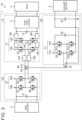
- An installation location of the relay 14 is not limited to the above-described embodiment. As measures against a short circuit of the smoothing capacitor 12, the relay 14 just needs to be provided in a power line between the smoothing capacitor 12 and the first winding 41. As shown in FIG. 2 , first to sixth installation locations 14A, 14B, 14C, 14D, 14E, 14F may be used as an installation location of the relay 14 in this case.
- the first installation location 14A is a power line between the first winding 41 and a connection point between the switching elements S1, S2.
- the second installation location 14B is a power line between the first winding 41 and a connection point between the switching elements S3, S4.
- the third installation location 14C is a power line connecting the upper side of the switching arm 13a with the upper side of the switching arm 13b.
- the fourth installation location 14D is a power line connecting the lower side of the switching arm 13a with the lower side of the switching arm 13b.
- the fifth installation location 14E is a power line connecting the upper side of the switching arm 13a with the upper side of the smoothing capacitor 12.
- the sixth installation location 14F is a power line connecting the upper side of the switching arm 13b with the upper side of the smoothing capacitor 12.
- the relay 14 just needs to be provided in at least any one of the first to sixth installation locations 14A, 14B, 14C, 14D, 14E, 14F.
- the number of the relays 14 is not limited to one and may be installed at multiple installation locations.
- a short circuit of the first switching circuit 10 is not limited to the smoothing capacitor 12, and it is conceivable that a short circuit occurs even in the switching elements of the first bridge circuit 13.
- the relay 14 just needs to be provided in a power line between the first bridge circuit 13 and the first winding 41.
- the first and second installation locations 14A, 14B may be used as an installation location of the relay 14 in this case.
- the relay 14 just needs to be provided in at least any one of the first and second installation locations 14A, 14B.
- the number of the relays 14 is not limited to one, and the relays 14 may be respectively installed in the first and second installation locations 14A, 14B.
Abstract
A power conversion apparatus (1) includes a transformer (40) including a first winding (41), a second winding (42), and a third winding (43), a first switching circuit (10) connected between an external power supply (2) and the first winding (41), a second switching circuit (20) connected between a main battery (3) and the second winding (42), and a third switching circuit (30) connected between an auxiliary battery (4) and the third winding (43). The first switching circuit (10) includes a power factor correction circuit (11), a smoothing capacitor (12) configured to smooth a voltage of direct-current power output from the power factor correction circuit (11), and a relay (14) provided in a power line between the smoothing capacitor (12) and the first winding (41).
Description
- The invention relates to a power conversion apparatus.
-
Japanese Unexamined Patent Application Publication No. 2021-164338 JP 2021-164338 A JP 2021-164338 A - In the configuration described in
JP 2021-164338 A - The invention provides a power conversion apparatus capable of avoiding an overcurrent via a transformer.
- An aspect of the invention provides a power conversion apparatus. The power conversion apparatus includes a transformer including a first winding, a second winding, and a third winding, a first switching circuit connected between an external power supply and the first winding, the first switching circuit being configured to supply the first winding with electric power input from the external power supply, a second switching circuit connected between a main battery and the second winding, the second switching circuit being configured to supply the main battery with electric power input from the first switching circuit via the transformer, the second switching circuit being configured to supply the second winding with electric power output from the main battery, and a third switching circuit connected between an auxiliary battery and the third winding, the third switching circuit being configured to supply the auxiliary battery with electric power input from the second switching circuit via the transformer. The first switching circuit includes a power factor correction circuit configured to improve a power factor of alternating-current power input from the external power supply, a smoothing capacitor configured to smooth a voltage of direct-current power output from the power factor correction circuit, and a relay provided in a power line between the smoothing capacitor and the first winding.
- With this configuration, it is possible to selectively interrupt a current path between the first winding and the smoothing capacitor by switching the relay between an open state and a closed state. Therefore, when the relay is in an open state, the current path between the smoothing capacitor and the first winding is interrupted, so, if a short circuit occurs in the smoothing capacitor, flow of an overcurrent to the second switching circuit and the third switching circuit via the transformer is prevented.
- The first switching circuit may include a first bridge circuit configured to convert direct-current power, output from the power factor correction circuit, to alternating-current power and supply the alternating-current power to the first winding, and the relay may be provided in a power line between the first bridge circuit and the first winding.
- With this configuration, it is possible to selectively interrupt a current path between the first winding and the first bridge circuit by switching the relay between an open state and a closed state. Therefore, when the relay is in an open state, the current path between the switching element of the first bridge circuit and the first winding is interrupted, so, if a short circuit occurs in any one of the switching elements, flow of an overcurrent to the second switching circuit and the third switching circuit via the transformer is prevented.
- The main battery and the auxiliary battery may be mounted on an electrified vehicle, and, when the electrified vehicle is traveling, the relay is open, and electric power from the main battery may be transferred to the auxiliary battery via the transformer.
- With this configuration, when electric power from the main battery is transferred to the auxiliary battery while the electrified vehicle is traveling, flow of an overcurrent to the second switching circuit and the third switching circuit via the transformer is prevented by opening the relay if a short circuit occurs in the first switching circuit.
- According to the aspect of the invention, it is possible to selectively interrupt a current path between the first winding and the smoothing capacitor by switching the relay between an open state and a closed state. Therefore, when the relay is in an open state, the current path between the smoothing capacitor and the first winding is interrupted, so, if a short circuit occurs in the smoothing capacitor, flow of an overcurrent to the second switching circuit and the third switching circuit via the transformer is prevented.
- Features, advantages, and technical and industrial significance of exemplary embodiments of the invention will be described below with reference to the accompanying drawings, in which like signs denote like elements, and wherein:
-
FIG. 1 is a circuit diagram that shows a power conversion apparatus according to an embodiment; -
FIG. 2 is a circuit diagram for illustrating an installation location of a relay between a smoothing capacitor and a winding in a PFC-side circuit; and -
FIG. 3 is a circuit diagram for illustrating an installation location of a relay between a switching element and a winding in a PFC-side circuit. - Hereinafter, a power conversion apparatus according to an embodiment of the invention will be specifically described with reference to the accompanying drawings. The invention is not limited to the embodiment described below.
-
FIG. 1 is a circuit diagram that shows the power conversion apparatus according to the embodiment. Thepower conversion apparatus 1 is mounted on a vehicle Ve that is externally chargeable. The vehicle Ve is an electrified vehicle including a battery allowed to be charged with electric power supplied from an external source and a drive motor configured to be driven by using electric power from the battery. Examples of the vehicle Ve include a plug-in hybrid electric vehicle (PHEV) and a battery electric vehicle (BEV). Thepower conversion apparatus 1 is used to supply electric power from an alternating-current power supply, such as a commercial power supply and a domestic power supply, to a battery mounted on the vehicle Ve and to supply alternating-current power from the battery mounted on the vehicle Ve to an electrical apparatus outside the vehicle Ve. In other words, thepower conversion apparatus 1 functions as a charger and an AC feeder. - The
power conversion apparatus 1 supplies electric power among anexternal power supply 2, amain battery 3, and anauxiliary battery 4. Theexternal power supply 2 is an alternating-current power supply, such as a commercial power supply (system power supply) and a domestic power supply. Themain battery 3 and theauxiliary battery 4 are direct-current power supplies mounted on the vehicle Ve. Themain battery 3 is a secondary battery that stores electric power to be supplied to the drive motor. Themain battery 3 supplies motoring electric power to the motor and is charged with electric power generated by regenerative braking with the motor. Theauxiliary battery 4 is a secondary battery that is charged with electric power to be supplied to auxiliaries such as an audio device, a room light, and an air conditioner mounted on the vehicle Ve. Thepower conversion apparatus 1 supplies electric power, supplied from theexternal power supply 2, to themain battery 3 and theauxiliary battery 4. Thepower conversion apparatus 1 supplies electric power from themain battery 3 to theauxiliary battery 4. In other words, thepower conversion apparatus 1 functions as an auxiliary DC-DC converter in addition to the charger and the AC feeder. - The
power conversion apparatus 1 includes afirst switching circuit 10, asecond switching circuit 20, athird switching circuit 30, and atransformer 40. Themain battery 3 is connected to thesecond switching circuit 20. Theauxiliary battery 4 is connected to thethird switching circuit 30. When external charging is performed, theexternal power supply 2 is connected to thefirst switching circuit 10 as shown inFIG. 1 . Thepower conversion apparatus 1 transfers electric power via thetransformer 40 among theexternal power supply 2, themain battery 3, and theauxiliary battery 4. - The
transformer 40 includes a first winding 41, a second winding 42, and a third winding 43. The first winding 41, the second winding 42, and the third winding 43 are magnetically coupled to one another. Both ends of the first winding 41 are connected to thefirst switching circuit 10. Both ends of the second winding 42 are connected to thesecond switching circuit 20. Both ends of the third winding 43 are connected to thethird switching circuit 30. - The
first switching circuit 10 is connected between theexternal power supply 2 and the first winding 41. Thefirst switching circuit 10 supplies the first winding 41 with electric power supplied from theexternal power supply 2. Thefirst switching circuit 10 includes a power factor correction (PFC)circuit 11, asmoothing capacitor 12, afirst bridge circuit 13, and arelay 14. - The
PFC circuit 11 improves the power factor of alternating-current power input from theexternal power supply 2, converts the alternating-current power to direct-current power, and outputs the direct-current power to thefirst bridge circuit 13. During external charging, theexternal power supply 2 is connected to alternating-current terminals of thePFC circuit 11. Thefirst bridge circuit 13 is connected to a positive electrode terminal and a negative electrode terminal of thePFC circuit 11. - The
smoothing capacitor 12 smooths the voltage of direct-current power output from thePFC circuit 11. Thesmoothing capacitor 12 is connected to power lines between thePFC circuit 11 and thefirst bridge circuit 13. Thesmoothing capacitor 12 is a first capacitor. - The
first bridge circuit 13 is a full-bridge circuit connected to the positive electrode terminal and negative electrode terminal of thePFC circuit 11. Thefirst bridge circuit 13 includes aswitching arm 13a and aswitching arm 13b. The switchingarm 13a includes switching elements S1, S2 connected in series. The switchingarm 13b includes switching elements S3, S4 connected in series. The switchingarms capacitor 12 is connected in parallel with the switchingarms arms capacitor 12 is connected to the positive electrode terminal of thePFC circuit 11. A lower-side parallel connection point among the switchingarms capacitor 12 is connected to the negative electrode terminal of thePFC circuit 11. The first winding 41 is connected between a connection point between the switching element S1 and the switching element S2 and a connection point between the switching element S3 and the switching element S4. - The
relay 14 is provided in a power line between thefirst bridge circuit 13 and the first winding 41. Therelay 14 is provided in a power line between one end of the first winding 41 and the connection point between the switching element S3 and the switching element S4. When therelay 14 is in a closed state (ON state), the first winding 41 and thefirst switching circuit 10 are connected such that a current can pass between the first winding 41 and thefirst switching circuit 10. On the other hand, when therelay 14 is in an open state (OFF state), the first winding 41 and thefirst switching circuit 10 are interrupted from each other such that no current can pass. - The
second switching circuit 20 is connected between themain battery 3 and the second winding 42. Thesecond switching circuit 20 supplies the second winding 42 with electric power from themain battery 3. Thesecond switching circuit 20 includes amain capacitor 21 and asecond bridge circuit 22. - The
main capacitor 21 is connected between a positive electrode line and a negative electrode line of themain battery 3. Themain capacitor 21 is a second capacitor. - The
second bridge circuit 22 is a full-bridge circuit connected to the positive electrode terminal and negative electrode terminal of themain battery 3. Thesecond bridge circuit 22 includes aswitching arm 22a and aswitching arm 22b. The switchingarm 22a includes switching elements S5, S6 connected in series. The switchingarm 22b includes switching elements S7, S8 connected in series. The switchingarms main capacitor 21 is connected in parallel with the switchingarms arms main capacitor 21 is connected to the positive electrode terminal of themain battery 3. A lower-side connection point among the switchingarms main capacitor 21 is connected to the negative electrode terminal of themain battery 3. The second winding 42 is connected between a connection point between the switching element S5 and the switching element S6 and a connection point between the switching element S7 and the switching element S8. - The
third switching circuit 30 is connected between theauxiliary battery 4 and the third winding 43. Thethird switching circuit 30 supplies the third winding 43 with electric power from theauxiliary battery 4. Thethird switching circuit 30 includes athird bridge circuit 31, anintermediate capacitor 32, and anauxiliary capacitor 33. - The
third bridge circuit 31 includes aswitching arm 31a and aswitching arm 31b. The switchingarm 31a includes switching elements S9, S10 connected in series. The switchingarm 31b includes switching elements S11, S12 connected in series. The switchingarms intermediate capacitor 32 is connected in parallel with the switchingarms - The
auxiliary capacitor 33 is connected between a lower-side parallel connection point among the switchingarms intermediate capacitor 32 and a midway point of the third winding 43. The midway point of the third winding 43 is connected to the positive electrode terminal of theauxiliary battery 4. The lower-side parallel connection point among the switchingarms intermediate capacitor 32 is connected to the negative electrode terminal of theauxiliary battery 4. The midway point of the third winding 43 is a midway point of a conductor wire forming the third winding 43. The midway point may be a center tap provided at the middle point of a conductor wire forming the third winding 43. Theauxiliary capacitor 33 is a third capacitor. Theintermediate capacitor 32 is a fourth capacitor. - Diodes are respectively connected to the switching elements S1, S2, S3, S4, S5, S6, S7, S8, S9, S10, S11, S12 such that anode terminals are respectively connected to the lower end sides of the switching elements S1, S2, S3, S4, S5, S6, S7, S8, S9, S10, S11, S12. Each of the switching elements S1, S2, S3, S4, S5, S6, S7, S8, S9, S10, S11, S12 is made up of an insulated gate bipolar transistor (IGBT) or a metal oxide semiconductor field effect transistor (MOSFET).
- Here, the operation of the
power conversion apparatus 1 will be described. - The operation of the
power conversion apparatus 1 is different between a case where electric power is supplied between theexternal power supply 2 and themain battery 3 in a state where the vehicle Ve is stopped (charger or AC feeder) and a case where electric power is supplied between themain battery 3 and theauxiliary battery 4 in a state where the vehicle Ve is traveling (auxiliary DC-DC converter). - Initially, the operation of the
power conversion apparatus 1 in the case where electric power is supplied between theexternal power supply 2 and themain battery 3 in a state where the vehicle Ve is stopped will be described. When thepower conversion apparatus 1 functions as a charger or an AC feeder, theexternal power supply 2 is connected to thePFC circuit 11. For example, an external power supply 2-side charging plug is connected to a charging port provided on the vehicle Ve. An input terminal of thepower conversion apparatus 1, that is, the alternating-current terminal of thePFC circuit 11, is provided at the charging port. - When the
main battery 3 is charged by using theexternal power supply 2 in a state where the vehicle Ve is stopped, thepower conversion apparatus 1 keeps therelay 14 in a closed state and transfers electric power from theexternal power supply 2 to thesecond switching circuit 20 via thefirst switching circuit 10 and thetransformer 40. - In this case, the
PFC circuit 11 controls the current flowing through the alternating-current terminal of thePFC circuit 11 through the switching operation such that the temporal waveform of current flowing through the alternating-current terminal is approximated to or brought into coincidence with the temporal waveform of alternating-current voltage output from theexternal power supply 2. While thePFC circuit 11 performs the operation to improve the power factor, thePFC circuit 11 converts alternating-current power input from theexternal power supply 2 to direct-current power and outputs the direct-current power to thefirst bridge circuit 13. ThePFC circuit 11 steps up the voltage of electric power supplied from theexternal power supply 2 and outputs the electric power to thefirst bridge circuit 13. In other words, a terminal voltage of the smoothingcapacitor 12 is adjusted by thePFC circuit 11. At this time, thepower conversion apparatus 1 adjusts the output voltage of thePFC circuit 11 such that the output voltage is higher than a voltage peak value of theexternal power supply 2. For example, the charging voltage of themain battery 3 is 350 V, and the charging voltage of theauxiliary battery 4 is 14.5 V. The output voltage of thePFC circuit 11 is adjusted to 400 V. - The
first bridge circuit 13 outputs alternating-current voltage to the first winding 41 by performing switching over the direct-current voltage output from thePFC circuit 11. In other words, thefirst bridge circuit 13 converts the direct-current power of thePFC circuit 11 to alternating-current power and supplies the alternating-current power to the first winding 41. When electric power is transferred to thesecond switching circuit 20 via thetransformer 40, electric power is transferred to thesecond switching circuit 20 in accordance with a difference between the switching timing of thefirst bridge circuit 13 and the switching timing of thesecond bridge circuit 22. - The
second switching circuit 20 supplies themain battery 3 with electric power transferred from thefirst switching circuit 10. In this case, thesecond bridge circuit 22 converts the alternating-current power transferred from the second winding 42 to direct-current power and supplies the direct-current power to themain battery 3. At this time, thesecond switching circuit 20 is capable of outputting electric power to themain battery 3 and outputting electric power to a load circuit connected to themain battery 3. - When the
main battery 3 is charged with electric power from theexternal power supply 2, theauxiliary battery 4 can be charged with electric power from theexternal power supply 2. Thepower conversion apparatus 1 transfers electric power from theexternal power supply 2 to thethird switching circuit 30 via thefirst switching circuit 10 and thetransformer 40. - When electric power is transferred to the
third switching circuit 30 via thetransformer 40, electric power is transferred to thethird switching circuit 30 in accordance with a difference between the switching timing of thefirst bridge circuit 13 and the switching timing of thethird bridge circuit 31. - The
third switching circuit 30 supplies theauxiliary battery 4 with electric power transferred from thefirst switching circuit 10. In this case, thethird switching circuit 30 initially charges theintermediate capacitor 32 with electric power supplied from thefirst switching circuit 10 via thetransformer 40. Through the switching operation of thethird bridge circuit 31, electric power is output from theintermediate capacitor 32 to theauxiliary battery 4 via the midway point of the third winding 43. - A terminal voltage of the
intermediate capacitor 32 is adjusted by controlling a phase difference that is a delay of the phase of switching of the switchingarms third bridge circuit 31 with respect to the phase of switching of the switchingarms first bridge circuit 13. Thethird bridge circuit 31 outputs alternating-current voltage to the third winding 43 by performing switching of voltage to theintermediate capacitor 32. In thepower conversion apparatus 1, the switchingarms third bridge circuit 31, a voltage (1 - D) times the terminal voltage of theintermediate capacitor 32 appears at both ends of each of theauxiliary battery 4 and theauxiliary capacitor 33. In this way, thethird bridge circuit 31 supplies electric power transferred from thefirst switching circuit 10 to theauxiliary battery 4 via theintermediate capacitor 32. At this time, thethird switching circuit 30 is capable of outputting electric power to theauxiliary battery 4 and outputting electric power to auxiliaries connected to theauxiliary battery 4. - With this configuration, in the
first switching circuit 10 and thethird switching circuit 30, the terminal voltage of the smoothingcapacitor 12 is stepped down to the terminal voltage of theintermediate capacitor 32, and the terminal voltage of theintermediate capacitor 32 is stepped down to the terminal voltage of theauxiliary battery 4 and the terminal voltage of theauxiliary capacitor 33. Electric power stepped down in a stepwise manner in this way is supplied. - Next, the operation of the
power conversion apparatus 1 in the case where electric power is supplied between themain battery 3 and theauxiliary battery 4 while the vehicle Ve is traveling will be described. When thepower conversion apparatus 1 functions as an auxiliary DC-DC converter, theexternal power supply 2 is isolated from thePFC circuit 11, and thePFC circuit 11 stops switching operation. When themain battery 3 supplies electric power to theauxiliary battery 4 while the vehicle Ve is traveling, thepower conversion apparatus 1 keeps therelay 14 in an open state and transfers electric power from themain battery 3 to thethird switching circuit 30 via thesecond switching circuit 20 and thetransformer 40. - In this case, the
second bridge circuit 22 outputs alternating-current voltage to the second winding 42 by performing switching over direct-current voltage output from themain battery 3. Thesecond bridge circuit 22 converts direct-current power from themain battery 3 to alternating-current power and supplies the alternating-current power to the second winding 42. When electric power is transferred to thethird switching circuit 30 via thetransformer 40, electric power is transferred to thethird switching circuit 30 in accordance with a difference between the switching timing of thesecond bridge circuit 22 and the switching timing of thethird bridge circuit 31. - The
third switching circuit 30 supplies theauxiliary battery 4 with electric power transferred from thesecond switching circuit 20. In this case, thethird switching circuit 30, as in the case during external charging, initially charges theintermediate capacitor 32 with electric power supplied from thesecond switching circuit 20 via thetransformer 40. Through the switching operation of thethird bridge circuit 31, electric power is output from theintermediate capacitor 32 to theauxiliary battery 4 via the midway point of the third winding 43. - In this way, when the vehicle Ve is traveling, electric power is supplied from the
main battery 3 to theauxiliary battery 4 in a state where therelay 14 is in an open state, and theauxiliary battery 4 is charged. If a short circuit occurs in the smoothingcapacitor 12 of thefirst switching circuit 10, a current path between the first winding 41 and the smoothingcapacitor 12 is interrupted because therelay 14 is in an open state. Flow of a current to the first winding 41 due to a short circuit of the smoothingcapacitor 12 is prevented by setting therelay 14 in an open state while the vehicle Ve is traveling. Therefore, while the vehicle Ve is traveling, an overcurrent in the main battery 3-side second switchingcircuit 20 and the auxiliary battery 4-side third switchingcircuit 30 is avoided by transfer of electric power from thefirst switching circuit 10 via thetransformer 40. - If a circuit does not include the
relay 14, thesecond switching circuit 20 and thefirst switching circuit 10 are driven such that the terminal voltage of the PFC-side smoothing capacitor 12 is kept at 400 V. Therefore, if a short circuit occurs in the smoothingcapacitor 12, a current flowing through the main battery 3-side circuit and a current flowing through the auxiliary battery 4-side circuit increase. In the case of, for example, 1000 W output, the value of current flowing through the main battery 3-side circuit increases from 4 Aac to 50 Aac, and the value of current flowing through the auxiliary battery 4-side circuit increases from 50 Aac to 180 Aac. A battery fuse can melt due to the increase in current. In contrast, in thepower conversion apparatus 1 including therelay 14, flow of an overcurrent to thesecond switching circuit 20 and thethird switching circuit 30 via thetransformer 40 is prevented. - As described above, according to the embodiment, when electric power is supplied from the
main battery 3 to theauxiliary battery 4, transfer of electric power from thefirst switching circuit 10 to thesecond switching circuit 20 and thethird switching circuit 30 via thetransformer 40 is prevented because therelay 14 is in an open state. Thus, when a short circuit occurs in the smoothingcapacitor 12 of thefirst switching circuit 10, flow of an overcurrent to thesecond switching circuit 20 and thethird switching circuit 30 is prevented because therelay 14 is in an open state. - An installation location of the
relay 14 is not limited to the above-described embodiment. As measures against a short circuit of the smoothingcapacitor 12, therelay 14 just needs to be provided in a power line between the smoothingcapacitor 12 and the first winding 41. As shown inFIG. 2 , first tosixth installation locations relay 14 in this case. - The
first installation location 14A is a power line between the first winding 41 and a connection point between the switching elements S1, S2. Thesecond installation location 14B is a power line between the first winding 41 and a connection point between the switching elements S3, S4. Thethird installation location 14C is a power line connecting the upper side of theswitching arm 13a with the upper side of theswitching arm 13b. Thefourth installation location 14D is a power line connecting the lower side of theswitching arm 13a with the lower side of theswitching arm 13b. Thefifth installation location 14E is a power line connecting the upper side of theswitching arm 13a with the upper side of the smoothingcapacitor 12. Thesixth installation location 14F is a power line connecting the upper side of theswitching arm 13b with the upper side of the smoothingcapacitor 12. - As measures against a short circuit of the smoothing
capacitor 12, therelay 14 just needs to be provided in at least any one of the first tosixth installation locations relays 14 is not limited to one and may be installed at multiple installation locations. - A short circuit of the
first switching circuit 10 is not limited to the smoothingcapacitor 12, and it is conceivable that a short circuit occurs even in the switching elements of thefirst bridge circuit 13. As measures against a short circuit in the switching elements S1, S2, S3, S4 of thefirst bridge circuit 13, therelay 14 just needs to be provided in a power line between thefirst bridge circuit 13 and the first winding 41. As shown inFIG. 3 , the first andsecond installation locations relay 14 in this case. - As for measures against a short circuit of the switching elements of the
first bridge circuit 13, therelay 14 just needs to be provided in at least any one of the first andsecond installation locations relays 14 is not limited to one, and therelays 14 may be respectively installed in the first andsecond installation locations
Claims (3)
- A power conversion apparatus (1) comprising:a transformer (40) including a first winding (41), a second winding (42), and a third winding (43);a first switching circuit (10) connected between an external power supply (2) and the first winding (41), the first switching circuit (10) being configured to supply the first winding (41) with electric power input from the external power supply (2);a second switching circuit (20) connected between a main battery (3) and the second winding (42), the second switching circuit (20) being configured to supply the main battery (3) with electric power input from the first switching circuit (10) via the transformer (40), the second switching circuit (20) being configured to supply the second winding (42) with electric power output from the main battery (3); anda third switching circuit (30) connected between an auxiliary battery (4) and the third winding (43), the third switching circuit (30) being configured to supply the auxiliary battery (4) with electric power input from the second switching circuit (20) via the transformer (40), whereinthe first switching circuit (10) includes a power factor correction circuit (11) configured to improve a power factor of alternating-current power input from the external power supply, a smoothing capacitor (12) configured to smooth a voltage of direct-current power output from the power factor correction circuit (11), and a relay (14) provided in a power line between the smoothing capacitor (12) and the first winding (41).
- The power conversion apparatus (1) according to claim 1, wherein:the first switching circuit (10) includes a first bridge circuit (13) configured to convert direct-current power, output from the power factor correction circuit (11), to alternating-current power and supply the alternating-current power to the first winding (41); andthe relay (14) is provided in a power line between the first bridge circuit (13) and the first winding (41).
- The power conversion apparatus (1) according to claim 1 or 2, wherein:
the main battery (3) and the auxiliary battery (4) are mounted on an electrified vehicle; and
when the electrified vehicle is traveling, the relay (14) is open, and electric power from the main battery (3) is transferred to the auxiliary battery (4) via the transformer (40).
Applications Claiming Priority (1)
| Application Number | Priority Date | Filing Date | Title |
|---|---|---|---|
| JP2022063786A JP2023154478A (en) | 2022-04-07 | 2022-04-07 | Power conversion equipment |
Publications (1)
| Publication Number | Publication Date |
|---|---|
| EP4258530A1 true EP4258530A1 (en) | 2023-10-11 |
Family
ID=85726297
Family Applications (1)
| Application Number | Title | Priority Date | Filing Date |
|---|---|---|---|
| EP23164105.1A Pending EP4258530A1 (en) | 2022-04-07 | 2023-03-24 | Power conversion apparatus |
Country Status (5)
| Country | Link |
|---|---|
| US (1) | US20230327562A1 (en) |
| EP (1) | EP4258530A1 (en) |
| JP (1) | JP2023154478A (en) |
| KR (1) | KR20230144457A (en) |
| CN (1) | CN116896049A (en) |
Citations (4)
| Publication number | Priority date | Publication date | Assignee | Title |
|---|---|---|---|---|
| CN107284273A (en) * | 2017-07-11 | 2017-10-24 | 深圳市永联科技股份有限公司 | A kind of Vehicular charger main circuit of integrated DC/DC converters and its control |
| CN109624733A (en) * | 2018-11-28 | 2019-04-16 | 嘉善中正新能源科技有限公司 | It is a kind of for the DC/DC converter of high speed electric vehicle and the consolidation circuit of Vehicular charger |
| JP2021164338A (en) | 2020-04-01 | 2021-10-11 | 株式会社豊田中央研究所 | Power conversion device and power adjustment circuit |
| US20220045619A1 (en) * | 2020-08-04 | 2022-02-10 | Delta Electronics, Inc. | Charging and discharging device and charging and discharging system of electric vehicle |
-
2022
- 2022-04-07 JP JP2022063786A patent/JP2023154478A/en active Pending
-
2023
- 2023-01-27 US US18/160,370 patent/US20230327562A1/en active Pending
- 2023-01-31 KR KR1020230012857A patent/KR20230144457A/en unknown
- 2023-02-10 CN CN202310117979.XA patent/CN116896049A/en active Pending
- 2023-03-24 EP EP23164105.1A patent/EP4258530A1/en active Pending
Patent Citations (4)
| Publication number | Priority date | Publication date | Assignee | Title |
|---|---|---|---|---|
| CN107284273A (en) * | 2017-07-11 | 2017-10-24 | 深圳市永联科技股份有限公司 | A kind of Vehicular charger main circuit of integrated DC/DC converters and its control |
| CN109624733A (en) * | 2018-11-28 | 2019-04-16 | 嘉善中正新能源科技有限公司 | It is a kind of for the DC/DC converter of high speed electric vehicle and the consolidation circuit of Vehicular charger |
| JP2021164338A (en) | 2020-04-01 | 2021-10-11 | 株式会社豊田中央研究所 | Power conversion device and power adjustment circuit |
| US20220045619A1 (en) * | 2020-08-04 | 2022-02-10 | Delta Electronics, Inc. | Charging and discharging device and charging and discharging system of electric vehicle |
Also Published As
| Publication number | Publication date |
|---|---|
| JP2023154478A (en) | 2023-10-20 |
| US20230327562A1 (en) | 2023-10-12 |
| KR20230144457A (en) | 2023-10-16 |
| CN116896049A (en) | 2023-10-17 |
Similar Documents
| Publication | Publication Date | Title |
|---|---|---|
| EP3886304B1 (en) | On-board charger | |
| CN113261191B (en) | Bidirectional multiport power conversion system and method | |
| EP2434604A1 (en) | Power source device | |
| CN111641247B (en) | Charging circuit of vehicle-mounted charger, vehicle-mounted charger and charging control method | |
| US10787088B2 (en) | Vehicle electrical system with inverter, energy store, electrical machine and DC transmission terminal | |
| US20220216723A1 (en) | Charging system and electric vehicle | |
| WO2019234988A1 (en) | Charging device | |
| WO2023159704A1 (en) | Battery series-parallel connection switching main circuit without power output interruption, and system and method | |
| US20200016991A1 (en) | Conversion device, associated control method and associated vehicle | |
| EP3819159A1 (en) | Multi-port and multi-directional power conversion system for electric and/or hybrid vehicles | |
| CN110957934A (en) | Transformer winding switching method and device | |
| JP2020533946A (en) | Vehicle charger with DC / DC converter | |
| EP4258530A1 (en) | Power conversion apparatus | |
| JP7440586B2 (en) | power regulation circuit | |
| US11689112B2 (en) | DC-DC converter and vehicle | |
| US11699957B2 (en) | Energy conversion system, energy conversion method, and power system | |
| JP2018014794A (en) | Power conversion circuit | |
| US20230382249A1 (en) | Charging circuit having a direct-current terminal and an alternating-current terminal, and vehicle electrical system having a charging circuit | |
| KR101726285B1 (en) | Duplex dc-dc converter of non insulation type | |
| US11190075B2 (en) | Drive system | |
| JP4361334B2 (en) | DC / DC converter | |
| US11936297B2 (en) | DC-DC converter including first and second coils magnetically coupled such that current flows through second coil in forward direction of diode by mutual induction as current flowing through first coil from intermediate terminal to output terminal increases and vehicle | |
| EP4098474B1 (en) | Energy conversion system, energy conversion method, and power system | |
| JP7344834B2 (en) | Automotive power converter | |
| EP4231494A1 (en) | Converting circuit and charging apparatus |
Legal Events
| Date | Code | Title | Description |
|---|---|---|---|
| PUAI | Public reference made under article 153(3) epc to a published international application that has entered the european phase |
Free format text: ORIGINAL CODE: 0009012 |
|
| STAA | Information on the status of an ep patent application or granted ep patent |
Free format text: STATUS: REQUEST FOR EXAMINATION WAS MADE |
|
| 17P | Request for examination filed |
Effective date: 20230324 |
|
| AK | Designated contracting states |
Kind code of ref document: A1 Designated state(s): AL AT BE BG CH CY CZ DE DK EE ES FI FR GB GR HR HU IE IS IT LI LT LU LV MC ME MK MT NL NO PL PT RO RS SE SI SK SM TR |