EP4258015A1 - Système de support pour un appareil de balayage de coordonnées mobile - Google Patents
Système de support pour un appareil de balayage de coordonnées mobile Download PDFInfo
- Publication number
- EP4258015A1 EP4258015A1 EP23166834.4A EP23166834A EP4258015A1 EP 4258015 A1 EP4258015 A1 EP 4258015A1 EP 23166834 A EP23166834 A EP 23166834A EP 4258015 A1 EP4258015 A1 EP 4258015A1
- Authority
- EP
- European Patent Office
- Prior art keywords
- measuring device
- scanner
- aspects
- mount
- pole mount
- Prior art date
- Legal status (The legal status is an assumption and is not a legal conclusion. Google has not performed a legal analysis and makes no representation as to the accuracy of the status listed.)
- Pending
Links
Images


Classifications
-
- G—PHYSICS
- G01—MEASURING; TESTING
- G01S—RADIO DIRECTION-FINDING; RADIO NAVIGATION; DETERMINING DISTANCE OR VELOCITY BY USE OF RADIO WAVES; LOCATING OR PRESENCE-DETECTING BY USE OF THE REFLECTION OR RERADIATION OF RADIO WAVES; ANALOGOUS ARRANGEMENTS USING OTHER WAVES
- G01S17/00—Systems using the reflection or reradiation of electromagnetic waves other than radio waves, e.g. lidar systems
- G01S17/86—Combinations of lidar systems with systems other than lidar, radar or sonar, e.g. with direction finders
-
- F—MECHANICAL ENGINEERING; LIGHTING; HEATING; WEAPONS; BLASTING
- F16—ENGINEERING ELEMENTS AND UNITS; GENERAL MEASURES FOR PRODUCING AND MAINTAINING EFFECTIVE FUNCTIONING OF MACHINES OR INSTALLATIONS; THERMAL INSULATION IN GENERAL
- F16M—FRAMES, CASINGS OR BEDS OF ENGINES, MACHINES OR APPARATUS, NOT SPECIFIC TO ENGINES, MACHINES OR APPARATUS PROVIDED FOR ELSEWHERE; STANDS; SUPPORTS
- F16M11/00—Stands or trestles as supports for apparatus or articles placed thereon Stands for scientific apparatus such as gravitational force meters
- F16M11/02—Heads
- F16M11/04—Means for attachment of apparatus; Means allowing adjustment of the apparatus relatively to the stand
- F16M11/06—Means for attachment of apparatus; Means allowing adjustment of the apparatus relatively to the stand allowing pivoting
- F16M11/08—Means for attachment of apparatus; Means allowing adjustment of the apparatus relatively to the stand allowing pivoting around a vertical axis, e.g. panoramic heads
-
- F—MECHANICAL ENGINEERING; LIGHTING; HEATING; WEAPONS; BLASTING
- F16—ENGINEERING ELEMENTS AND UNITS; GENERAL MEASURES FOR PRODUCING AND MAINTAINING EFFECTIVE FUNCTIONING OF MACHINES OR INSTALLATIONS; THERMAL INSULATION IN GENERAL
- F16M—FRAMES, CASINGS OR BEDS OF ENGINES, MACHINES OR APPARATUS, NOT SPECIFIC TO ENGINES, MACHINES OR APPARATUS PROVIDED FOR ELSEWHERE; STANDS; SUPPORTS
- F16M11/00—Stands or trestles as supports for apparatus or articles placed thereon Stands for scientific apparatus such as gravitational force meters
- F16M11/20—Undercarriages with or without wheels
- F16M11/2007—Undercarriages with or without wheels comprising means allowing pivoting adjustment
- F16M11/2014—Undercarriages with or without wheels comprising means allowing pivoting adjustment around a vertical axis
-
- F—MECHANICAL ENGINEERING; LIGHTING; HEATING; WEAPONS; BLASTING
- F16—ENGINEERING ELEMENTS AND UNITS; GENERAL MEASURES FOR PRODUCING AND MAINTAINING EFFECTIVE FUNCTIONING OF MACHINES OR INSTALLATIONS; THERMAL INSULATION IN GENERAL
- F16M—FRAMES, CASINGS OR BEDS OF ENGINES, MACHINES OR APPARATUS, NOT SPECIFIC TO ENGINES, MACHINES OR APPARATUS PROVIDED FOR ELSEWHERE; STANDS; SUPPORTS
- F16M11/00—Stands or trestles as supports for apparatus or articles placed thereon Stands for scientific apparatus such as gravitational force meters
- F16M11/20—Undercarriages with or without wheels
- F16M11/2092—Undercarriages with or without wheels comprising means allowing depth adjustment, i.e. forward-backward translation of the head relatively to the undercarriage
-
- F—MECHANICAL ENGINEERING; LIGHTING; HEATING; WEAPONS; BLASTING
- F16—ENGINEERING ELEMENTS AND UNITS; GENERAL MEASURES FOR PRODUCING AND MAINTAINING EFFECTIVE FUNCTIONING OF MACHINES OR INSTALLATIONS; THERMAL INSULATION IN GENERAL
- F16M—FRAMES, CASINGS OR BEDS OF ENGINES, MACHINES OR APPARATUS, NOT SPECIFIC TO ENGINES, MACHINES OR APPARATUS PROVIDED FOR ELSEWHERE; STANDS; SUPPORTS
- F16M11/00—Stands or trestles as supports for apparatus or articles placed thereon Stands for scientific apparatus such as gravitational force meters
- F16M11/20—Undercarriages with or without wheels
- F16M11/24—Undercarriages with or without wheels changeable in height or length of legs, also for transport only, e.g. by means of tubes screwed into each other
-
- F—MECHANICAL ENGINEERING; LIGHTING; HEATING; WEAPONS; BLASTING
- F16—ENGINEERING ELEMENTS AND UNITS; GENERAL MEASURES FOR PRODUCING AND MAINTAINING EFFECTIVE FUNCTIONING OF MACHINES OR INSTALLATIONS; THERMAL INSULATION IN GENERAL
- F16M—FRAMES, CASINGS OR BEDS OF ENGINES, MACHINES OR APPARATUS, NOT SPECIFIC TO ENGINES, MACHINES OR APPARATUS PROVIDED FOR ELSEWHERE; STANDS; SUPPORTS
- F16M13/00—Other supports for positioning apparatus or articles; Means for steadying hand-held apparatus or articles
- F16M13/04—Other supports for positioning apparatus or articles; Means for steadying hand-held apparatus or articles for supporting on, or holding steady relative to, a person, e.g. by chains, e.g. rifle butt or pistol grip supports, supports attached to the chest or head
-
- G—PHYSICS
- G01—MEASURING; TESTING
- G01C—MEASURING DISTANCES, LEVELS OR BEARINGS; SURVEYING; NAVIGATION; GYROSCOPIC INSTRUMENTS; PHOTOGRAMMETRY OR VIDEOGRAMMETRY
- G01C15/00—Surveying instruments or accessories not provided for in groups G01C1/00 - G01C13/00
- G01C15/002—Active optical surveying means
-
- G—PHYSICS
- G01—MEASURING; TESTING
- G01S—RADIO DIRECTION-FINDING; RADIO NAVIGATION; DETERMINING DISTANCE OR VELOCITY BY USE OF RADIO WAVES; LOCATING OR PRESENCE-DETECTING BY USE OF THE REFLECTION OR RERADIATION OF RADIO WAVES; ANALOGOUS ARRANGEMENTS USING OTHER WAVES
- G01S17/00—Systems using the reflection or reradiation of electromagnetic waves other than radio waves, e.g. lidar systems
- G01S17/02—Systems using the reflection of electromagnetic waves other than radio waves
- G01S17/06—Systems determining position data of a target
- G01S17/42—Simultaneous measurement of distance and other co-ordinates
-
- G—PHYSICS
- G01—MEASURING; TESTING
- G01S—RADIO DIRECTION-FINDING; RADIO NAVIGATION; DETERMINING DISTANCE OR VELOCITY BY USE OF RADIO WAVES; LOCATING OR PRESENCE-DETECTING BY USE OF THE REFLECTION OR RERADIATION OF RADIO WAVES; ANALOGOUS ARRANGEMENTS USING OTHER WAVES
- G01S17/00—Systems using the reflection or reradiation of electromagnetic waves other than radio waves, e.g. lidar systems
- G01S17/88—Lidar systems specially adapted for specific applications
- G01S17/89—Lidar systems specially adapted for specific applications for mapping or imaging
-
- G—PHYSICS
- G01—MEASURING; TESTING
- G01S—RADIO DIRECTION-FINDING; RADIO NAVIGATION; DETERMINING DISTANCE OR VELOCITY BY USE OF RADIO WAVES; LOCATING OR PRESENCE-DETECTING BY USE OF THE REFLECTION OR RERADIATION OF RADIO WAVES; ANALOGOUS ARRANGEMENTS USING OTHER WAVES
- G01S17/00—Systems using the reflection or reradiation of electromagnetic waves other than radio waves, e.g. lidar systems
- G01S17/88—Lidar systems specially adapted for specific applications
- G01S17/93—Lidar systems specially adapted for specific applications for anti-collision purposes
- G01S17/931—Lidar systems specially adapted for specific applications for anti-collision purposes of land vehicles
-
- G—PHYSICS
- G01—MEASURING; TESTING
- G01S—RADIO DIRECTION-FINDING; RADIO NAVIGATION; DETERMINING DISTANCE OR VELOCITY BY USE OF RADIO WAVES; LOCATING OR PRESENCE-DETECTING BY USE OF THE REFLECTION OR RERADIATION OF RADIO WAVES; ANALOGOUS ARRANGEMENTS USING OTHER WAVES
- G01S7/00—Details of systems according to groups G01S13/00, G01S15/00, G01S17/00
- G01S7/48—Details of systems according to groups G01S13/00, G01S15/00, G01S17/00 of systems according to group G01S17/00
- G01S7/4808—Evaluating distance, position or velocity data
-
- G—PHYSICS
- G01—MEASURING; TESTING
- G01S—RADIO DIRECTION-FINDING; RADIO NAVIGATION; DETERMINING DISTANCE OR VELOCITY BY USE OF RADIO WAVES; LOCATING OR PRESENCE-DETECTING BY USE OF THE REFLECTION OR RERADIATION OF RADIO WAVES; ANALOGOUS ARRANGEMENTS USING OTHER WAVES
- G01S7/00—Details of systems according to groups G01S13/00, G01S15/00, G01S17/00
- G01S7/48—Details of systems according to groups G01S13/00, G01S15/00, G01S17/00 of systems according to group G01S17/00
- G01S7/481—Constructional features, e.g. arrangements of optical elements
- G01S7/4814—Constructional features, e.g. arrangements of optical elements of transmitters alone
- G01S7/4815—Constructional features, e.g. arrangements of optical elements of transmitters alone using multiple transmitters
-
- G—PHYSICS
- G01—MEASURING; TESTING
- G01S—RADIO DIRECTION-FINDING; RADIO NAVIGATION; DETERMINING DISTANCE OR VELOCITY BY USE OF RADIO WAVES; LOCATING OR PRESENCE-DETECTING BY USE OF THE REFLECTION OR RERADIATION OF RADIO WAVES; ANALOGOUS ARRANGEMENTS USING OTHER WAVES
- G01S7/00—Details of systems according to groups G01S13/00, G01S15/00, G01S17/00
- G01S7/48—Details of systems according to groups G01S13/00, G01S15/00, G01S17/00 of systems according to group G01S17/00
- G01S7/481—Constructional features, e.g. arrangements of optical elements
- G01S7/4817—Constructional features, e.g. arrangements of optical elements relating to scanning
-
- G—PHYSICS
- G01—MEASURING; TESTING
- G01S—RADIO DIRECTION-FINDING; RADIO NAVIGATION; DETERMINING DISTANCE OR VELOCITY BY USE OF RADIO WAVES; LOCATING OR PRESENCE-DETECTING BY USE OF THE REFLECTION OR RERADIATION OF RADIO WAVES; ANALOGOUS ARRANGEMENTS USING OTHER WAVES
- G01S7/00—Details of systems according to groups G01S13/00, G01S15/00, G01S17/00
- G01S7/48—Details of systems according to groups G01S13/00, G01S15/00, G01S17/00 of systems according to group G01S17/00
- G01S7/51—Display arrangements
-
- F—MECHANICAL ENGINEERING; LIGHTING; HEATING; WEAPONS; BLASTING
- F16—ENGINEERING ELEMENTS AND UNITS; GENERAL MEASURES FOR PRODUCING AND MAINTAINING EFFECTIVE FUNCTIONING OF MACHINES OR INSTALLATIONS; THERMAL INSULATION IN GENERAL
- F16M—FRAMES, CASINGS OR BEDS OF ENGINES, MACHINES OR APPARATUS, NOT SPECIFIC TO ENGINES, MACHINES OR APPARATUS PROVIDED FOR ELSEWHERE; STANDS; SUPPORTS
- F16M2200/00—Details of stands or supports
- F16M2200/04—Balancing means
- F16M2200/044—Balancing means for balancing rotational movement of the undercarriage
-
- F—MECHANICAL ENGINEERING; LIGHTING; HEATING; WEAPONS; BLASTING
- F16—ENGINEERING ELEMENTS AND UNITS; GENERAL MEASURES FOR PRODUCING AND MAINTAINING EFFECTIVE FUNCTIONING OF MACHINES OR INSTALLATIONS; THERMAL INSULATION IN GENERAL
- F16M—FRAMES, CASINGS OR BEDS OF ENGINES, MACHINES OR APPARATUS, NOT SPECIFIC TO ENGINES, MACHINES OR APPARATUS PROVIDED FOR ELSEWHERE; STANDS; SUPPORTS
- F16M2200/00—Details of stands or supports
- F16M2200/06—Arms
- F16M2200/063—Parallelogram arms
Definitions
- the present disclosure relates to a system and method that can facilitate measuring, capturing, and storing a three-dimensional (3D) representation of a surrounding environment using a mobile/portable coordinate scanner, particularly to a stabilization or support system to improve data capturing by such a scanner.
- 3D three-dimensional
- a TOF laser scanner steers a beam of light to a non-cooperative target, such as a diffusely scattering surface of an object.
- a distance meter in the device measures the distance to the object, and angular encoders measure the angles of the emitted light. The measured distance and angles enable a processor in the device to determine the 3D coordinates of the target.
- a TOF laser scanner (or simply TOF scanner) is a scanner in which the distance to a target point is determined based on the speed of light in the air between the scanner and a target point.
- Phase shift laser scanners determine the distance to the object by the phase shift between the outgoing and returning signal (i.e., calculating the "shift” or "displacement” of the reflective wave compared to the outgoing wave).
- Laser scanners are typically used for scanning closed or open spaces such as interior areas of buildings, industrial installations, and tunnels. They may be used, for example, in industrial applications and accident reconstruction applications.
- a laser scanner optically scans and measures objects in a volume around the scanner by acquiring data points representing object surfaces within the volume. Such data points are obtained by transmitting a beam of light onto the objects and collecting the reflected or scattered light to determine the distance, two angles (i.e., azimuth and a zenith angle), and optionally a gray-scale value.
- This raw scan data is collected, stored, and sent to a processor or processors to generate a 3D image representing the scanned area or object.
- an image requires at least three values for each data point. These three values may include the distance and two angles or maybe transformed values, such as the x, y, z coordinates.
- an image is also based on a fourth gray-scale value, which is a value related to the irradiance of scattered light returning to the scanner.
- the beam steering mechanism includes a first motor that steers the beam of light about a first axis by a first angle that is measured by a first angular encoder (or another angle transducer).
- the beam steering mechanism also includes a second motor that steers the beam of light about a second axis by a second angle that is measured by a second angular encoder (or another angle transducer).
- Many contemporary laser scanners include a camera mounted on the laser scanner for gathering digital images of the environment and presenting the 2D digital images to an operator of the laser scanner. By viewing the camera images, the operator of the scanner can determine the field of view of the measured volume and adjust settings on the laser scanner to measure over a larger or smaller region of space.
- the camera's digital images may be transmitted to a processor to add color to the scanner image.
- To generate a color scanner image at least three positional coordinates (such as x, y, z) and three color values (such as red, green, blue "RGB”) are collected for each data point.
- a 3D image of a scene may require multiple scans from different registration stationary positions.
- the overlapping scans are registered in a joint coordinate system, for example, as described in U.S. Published Patent Application No. 2012/0069352 ( ⁇ 352), the contents of which are incorporated herein by reference.
- Such registration is performed by matching targets in overlapping regions of the multiple scans.
- the targets may be artificial targets such as spheres, checkerboards, or natural features such as corners or edges of walls.
- Some registration procedures involve relatively time-consuming manual procedures such as identifying by a user each target and matching the targets obtained by the scanner in each of the different registration positions.
- Some registration procedures also require establishing an external "control network" of registration targets measured by an external device such as a total station.
- the registration method disclosed in ⁇ 352 eliminates the need for user matching of registration targets and establishing a control network.
- a laser scanner is usually mounted on a tripod or instrument stand while measuring the 3D coordinates of its surroundings. An operator is required to move the tripod from location to location as measurements are taken.
- a mobile three-dimensional (3D) measuring system includes a 3D measuring device, and a support apparatus.
- the 3D measuring device is coupled to the support apparatus.
- the support apparatus includes a pole mount that includes a gimbal at the top of the pole mount, wherein the 3D measuring device is attached to the gimbal.
- the support apparatus further includes a counterweight at the bottom of the pole mount, the counterweight matches a weight of the 3D measuring device.
- the 3D measuring device is a time-of flight scanner.
- the 3D measuring device comprises a LIDAR sensor to capture a digital representation of an environment as the 3D measuring system is transported in the environment.
- the 3D measuring device continuously transmits a captured data to a computing system as the 3D measuring device is moved in an environment.
- the computing system generates a 3D point cloud representing the environment based on the captured data and stores the 3D point cloud.
- the 3D measuring device is configured for wireless communication with the computing system.
- the computing system generates a 2D projection as live feedback of a movement of the 3D measuring device.
- the 2D projection is displayed on a computing device, separate from the 3D measuring device.
- the computing device is handheld by an operator.
- the 2D projection is displayed at a first map tile level, and in response to zooming into a portion of the 2D projection, a second map tile level is displayed.
- the pole mount is coupled to a body mount that is worn by an operator.
- the body mount comprises one or more straps for the operator to wear the body mount.
- the one or more straps are adjustable.
- the pole mount is coupled to the body mount via a mechanical arm.
- the mechanical arm can extend using at least two joints.
- the pole mount is coupled to a moveable platform.
- the moveable platform is moved manually, autonomously, or semi-autonomously.
- the counterweight at the bottom of the pole mount comprises one or more accessories of the 3D measuring system.
- the 3D measuring system comprises a power source for the 3D measuring device.
- the pole mount is hollow and one or more wires are routed to the 3D measuring device through the pole mount.
- a mobile 3D scanner that can include one or more sensors, such as LIDAR.
- the sensors can be off-the-shelf components, for example, LIDAR devices manufactured by VELODYNE ® or any other manufacturer.
- the 3D scanner uses the sensors to capture a surrounding environment's digital three-dimensional (3D) representation.
- the 3D scanner can be carried, for example, as a handheld device that facilitates measuring, capturing, and storing the 3D representation of the surrounding environment.
- the 3D scanner can be carried, for example, mounted to an autonomous/semi-autonomous moveable platform/vehicle, such as a robot, a vehicle, etc.
- the "portability" or the “mobility” of the 3D scanner facilitates continuously capturing the digital representation of the surrounding environment as the 3D scanner is moved in an environment (for example, as the operator walks, vehicle drives, etc.). Instead, in existing solutions, the 3D scanner would be placed at a first position in the environment to capture a first portion of the surrounding environment, then moved to a second position in the environment to capture a second portion, and so on. The two or more digital representations captured from the respective positions, are then registered with each other to generate a map of the surrounding environment in the existing solutions.
- the technical solutions described herein improve the speed at which the map (i.e., the 3D digital representation) is generated. For example, the time and effort required to move and place the 3D scanner from one position to another are reduced. Further, the continuous capturing reduces skipped or uncaptured areas because the 3D scanner could not be placed at a suitable position to capture an area. For example, areas behind an obstacle (e.g., column, wall, etc.), inside a cabinet/closet, maybe unreachable for stationary 3D scanners because of limited positions where a tripod or fixture can be placed.
- an obstacle e.g., column, wall, etc.
- the portability/mobility of the 3D scanner as opposed to capturing the digital representation when the 3D scanner is stationary introduces several technical challenges.
- An example technical challenge is the stabilization or support of the 3D scanner while being moved. Without stabilization, the captured digital representation can not only be inaccurate but also blur or smeer the data.
- the weight of the 3D scanner can exceed a desired predetermined weight threshold (e.g., 3 Lbs., 5 Lbs., etc.).
- the weight can cause an operator to be uncomfortable when carrying the 3D scanner around the environment for extended periods of time (e.g., 15 minutes, 20 minutes, etc.).
- Some existing solutions to reduce the weight of the 3D scanner reduce capabilities, e.g., reducing sensors, battery capacity, etc.
- Other existing solutions instead of reducing the weight, provide a body-mounted backpack, or other contraption, that the operator can "wear" and which supports the 3D scanner.
- body-mounted vests are clumsy and inflexible.
- the body-mounted contraption cannot be used to move the 3D scanner into certain areas where the user cannot reach, such as areas smaller than the operator (e.g., inside a cabinet, around a column, etc.).
- the technical solutions described herein address such portability-related technical challenges associated with a 3D scanner.
- the technical solutions described herein facilitate live scanning and mobile mapping using a 3D scanner by providing a support system with a three-axis gimbal at its center of gravity. Further, the technical solutions described herein isolate the 3D scanner from disturbances, tremors, shaking, or other such movements caused because of the 3D scanner being moved continuously during the scanning by the operator, platform, or a combination thereof. Further, the technical solutions described herein improve inertial stability and reduce a human operator's fatigue by distributing the weight of the 3D scanner away from the operator. For example, a body-mounted vest can be used to attach the technical solutions herein to distribute the weight of the 3D scanner.
- a neutral counterbalance is provided by the technical solutions described herein, using one or more components that are used by the 3D scanner, such as a battery or other accessories of the 3D scanner.
- the technical solutions described herein provide a practical application by moving the weight away from the hands of the operator.
- Technical solutions herein further stabilize the 3D scanner to improve the data captured by the 3D scanner while being transported in the environment.
- the technical solutions described herein extend the reach and agility of the 3D scanner. Accordingly, stabilized operations can include unrestricted and intuitive angular control of the 3D scanner and large lateral and vertical displacements from the operator's position.
- FIG. 1 depicts an example 3D scanning apparatus according to one or more aspects.
- an operator carries a 3D scanning apparatus 120, which includes two sensors 122.
- the sensors 122 are LIDAR devices in the depicted example; however, the sensors 122 can be any other TOF type of sensor.
- the sensor 122 such as a LIDAR device, facilitates determining the distance (ranges) of a point of an object in the sensor's field of view (FOV) by targeting the object with a light pulse (e.g., laser) and measuring the time for the reflected light to return to a receiver.
- the sensor 122 facilitates emitting and receiving the light pulses and measuring the time between emission and reception.
- the sensors 122 can be mounted on supporting mounts 2 in some examples. The mounting and positioning of the sensors with respect to the operator and/or each other can be different from that shown in the example of FIG. 1 .
- Each sensor 122 has a respective FOV 12.
- the at least two sensors 122 facilitate capturing complete (360 degrees) surroundings of the operator. It should be noted that although an operator is depicted to be carrying the measurement device 120 manually (on the back/hand) in FIG. 1 , in other examples, the measurement device 120 can be carried by the operator in a different manner. Further, in some examples, the measurement device 120 can be carried by a robotic/automated/semi-automated or manually moved platform in other examples.
- FIG. 2 depicts an example handheld measurement device 120 according to one or more aspects.
- the measurement device 120 operates using the same principles as the other measurement devices described herein, using one or more TOF-type sensors 122.
- the handheld measurement device 120 may be held differently from what is shown in FIG. 2 .
- FIG. 3 depicts an example view of the LIDAR sensor according to one or more examples.
- the sensor 122 is a puck-shaped LIDAR with sixteen scan lines 14 in a 30° vertical FOV 12 with respect to a vertical axis 5 of the sensor 122. It is understood that other types of sensors and/or lidars can be used in other examples with different FOV angles (e.g., 45 degrees) and/or with different resolutions (scan lines per degree/radian).
- the operator would have to perform multiple scans with the sensor in different poses (e.g., rotating or angling/tilting the measurement device 120).
- mobile mapping is the process of measuring and collecting geospatial data by a mobile 3D scanning system.
- the 3D scanning system can use a backpack, a trolley, a handheld device, an autonomous robot, or any other mobile form.
- the 3D scanning system uses remote sensing systems like LIDAR cameras in combination with inertial and navigation sensors, e.g., an inertial measurement unit (IMU), for mobile mapping.
- IMU inertial measurement unit
- simultaneous localization and mapping is a technique/algorithm that a mobile 3D scanning system uses to incrementally build a map of the surrounding environment while the 3D scanning system is moving or has been moved, simultaneously localizing itself on the map.
- a "map" is a 2D or 3D representation of the environment seen through the various sensors of the 3D scanning system.
- the map is represented internally as a grid map.
- the grid map is a 2D or 3D arranged collection of cells representing an area of the environment.
- the grid map stores, for every cell, a probability indicating if the cell area is occupied or not based on the measurement(s) from the 3D scanning system.
- the 3D scanning system can include LIDAR sensors which produce a 3D point cloud as output.
- Technical solutions are not restricted or limited to specific LIDAR sensors and can include LIDAR sensors from VELODYNE9, OUSTER ® , or any other manufacturer.
- FIG. 4 depicts a scanning system for capturing measurements in an environment according to one or more aspects.
- the scanning system 100 includes a computing system 110 coupled with a measurement device 120.
- the coupling facilitates electronic communication of data and instructions between the computing system 110 and the measurement device 120.
- the communication can be performed in a wired or wireless manner.
- the measurement device 120 can be a 3D scanner.
- the computing system 110 can be a computer server or any other type of computing device that facilitates remote storage and processing of the captured data 125.
- the captured data 125 from the measurement device 120 includes measurements of a portion of the environment.
- the captured data 125 is transmitted to the computing system 110 for processing and/or storage.
- the computing device 110 can store the captured data 125 locally, i.e., in a storage device in the computing device 110 itself, or remotely, i.e., in a storage device that is part of another computing device 150.
- the computing device 150 can be a computer server or any other type of computing device that facilitates remote storage and processing of the captured data 125.
- the captured data 125 from the measurement device 120 can include 2D images, 3D point clouds, a distance of each point in the point cloud(s) from the measurement device 120, color information at each point, radiance information at each point, and other such sensor data captured by the set of sensors 122 of the measurement device 120.
- sensors 122 can include a LIDAR 122A, a depth camera 122B, a camera 122C, etc.
- the 2D images can be panorama images (e.g., wide-angle images, ultra-wide-angle images, etc.).
- the measurement device 120 can also include an inertial measurement unit (IMU) 126 to keep track of a pose, including a 3D orientation, of the measurement device 120.
- the pose can be extrapolated by using the sensor data from sensors 122, the IMU 126, and/or from sensors besides the range finders.
- the measurement device 120 can also include a global positioning sensor (GPS) (not shown) or another such location-sensing module that facilitates identifying a global position of the measurement device 120.
- GPS global positioning sensor
- the measurement device 120 can also include a global positioning sensor (GPS) (not shown) or another such location-sensing module that facilitates identifying a global position of the measurement device 120.
- GPS global positioning sensor
- multiple measurement devices 120 can transmit respective captured data 125 to the computing system 110.
- Each of the measurement devices 120 transmits captured data 125 to the computing system 110 concurrently in some aspects.
- the distributed processing comprises running a subset of the operations for generating the map 130 on the measurement devices 120 and another subset of the operations on the computing system 110 (i.e., cloud platform), which can process data from the different measurement devices 120. Accordingly, the technical challenge of the limited processing power available at the measurement devices 120 (for example, necessitated by the portability) can be overcome. Further, the distributed processing facilitates updating the computing system 110 (for example, to correct errors, add features, etc.) faster than updating the (local) measurement devices 120.
- FIG. 5 depicts a block diagram of a structure of the distributed processing performed by the scanning system 100 to generate map 130 according to one or more aspects.
- the measurement device 120 transmits the captured data 125 to the computing system 110, i.e., a "cloud computing system.”
- the computing system 110 processes the captured data 125 to generate an output 215.
- the output 215 includes at least a portion of the map 130.
- one or more applications 192 receive the output 215.
- the one or more applications 190 can be software or computer programs in some aspects.
- the applications 192 may be executing on a computing device 190.
- the computing device 190 can be different from the computing system 110 in some aspects.
- the computing device 190 can be a mobile phone, a tablet computer, a laptop computer, or any other type of portable computing device that may have limited computing resources.
- the computing device 190 communicates with the computing system 110 in a wired or wireless manner, for example, using a computer network, such as the Internet.
- the computing device 190 is the computing system 110 itself, or part of the computing system 110.
- the computing device 190 can be the measurement device 120 itself or associated with the measurement device 120.
- the computing device 190 can transmit to the computing system 190, one or more requests 216 to change one or more portions of the map 130.
- the changes can be based on, for example, localization of a portion of the map 130 included in the output 215, resulting in misalignment.
- the computing system 110 can provide an application programming interface (API) 201 to facilitate communication with external components such as the measurement device 120 and the computing device 190.
- API application programming interface
- the API 201 can be accessed by the external components to provide the captured data 215, the requests 216, and to receive the output 215, the time-lapse of the 3D model 217, and other communications.
- Predetermined communication protocols and data structures are used to communicate the electronic data between the computing system 110 and the measurement device 120, and the computing device 190.
- standards associated with the robot operating system (ROS) can be used for transferring the data using *.BAG file protocols.
- Other types of predetermined data standards can be used in other examples, and the data structures and protocols used for the communication do not limit the technical solutions described herein.
- the computing system 110 can include a mapping module 210 that generates a trajectory of the measurement device 120 in the map 130 based on the captured data 125.
- the mapping module 210 can also be responsible for generating a point cloud representing the surrounding environment. In some examples, the point cloud is part of the map 130.
- FIG. 6 depicts an example point cloud.
- a "point cloud” 300 is a collection of individual 3D data points 301, with each data point 301 having a set coordinate on the X, Y, and Z-axis.
- a 3D model can be represented by rendering each of the data points 301 in the point cloud 300 together.
- the data compiled to create the point cloud 300 is taken from a room to depict the location of each door, window, and any other object (e.g., bed, rug, etc.) or surface in the room.
- the clarity (or quality) of details and specific types of features and structures will vary.
- the mapping module 210 is responsible for executing one or more SLAM algorithms, such as lidar SLAM 202, visual SLAM 204, etc.
- the mapping module 210 uses the captured data 215. Further, the mapping module 210 uses information about the actual measurement device 120 that captured the data, i.e., which sensors were used, calibrations, etc. With such information, the mapping module 210 performs mapping for the different types of sensors 122, i.e., lidars, cameras, IMUs 126, etc.
- the "mapping" includes aligning the measurements from the several sensors into a homogenous coordinate system as well as ensuring timestamp synchronization across the sensors.
- the mapping module 210 generates a 3D point cloud 300 in this manner.
- the computing system 110 further includes a colorization module 220, which in some aspects colorizes the 3D point cloud 300 that is generated by the mapping module 210.
- Colorization includes assigning a color to each data point 301 in the point cloud 300.
- the colorization can be performed using known techniques such as applying a "texture" using a color image captured by a camera.
- the color image can be a panoramic or fish-eye image in one or more examples.
- the color image can be aligned with the 3D point cloud 300 using photogrammetry 222 in one or more examples. Other techniques can also be used to colorize the 3D point cloud 300 in other examples.
- the 3D point cloud 300 with and/or without colorization is stored by the computing system 110 in a model storage 230.
- the 3D point cloud 300 is provided to the computing device 190 as part of the output 215.
- the computing device 190 also includes an instance of the mapping module 210.
- two different instances of the same mapping module 210 are executed, a first instance on the computing system 110, and a second instance on the computing device 190.
- the second instance has different (relaxed) settings from the first instance of the mapping module 210.
- the second instance performs a live mapping of the 3D point clouds in the output(s) 215 generated by the computing system 110.
- the second instance generates a preview of the map 130 using the outputs from the computing system 110.
- the generated preview can be 2D or 2.5D map (2.5D means a 2D map with depth information).
- the preview visualizes the 3D point cloud 300 with a lower predetermined resolution.
- the computing device 190 includes a diagnostics and logging module 195 that saves information about the settings and calibration of the computing device 190.
- FIG. 7 depicts a flowchart of a method 400 for generating the map 130 of a surrounding environment as the measurement device 120 is transported in the surrounding environment and provides, as feedback, a real-time preview of the map 130 that is being generated according to one or more aspects.
- the method 400 includes, at block 402, calibrating the sensors 122 of the one or more measurement devices 120.
- the multiple sensors are calibrated to generate measurements on a single trajectory and a common coordinate system of a point cloud.
- the coordinate systems of the multiple sensors have to be aligned to a single common coordinate system.
- the measurement device 120 includes two LIDAR sensors
- the measurements from both LIDAR sensors are aligned to a common (single) coordinate system.
- the common coordinate system can be that of one of the two LIDAR sensors or a third coordinate system independent of the two LIDAR sensors.
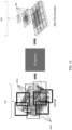
- FIG. 8 depicts an example scenario of calibrating two LIDAR sensors.
- a measurement device 120 in this case, a handheld TOF scanner, is placed in an environment 500, in this case, a room.
- the number of calibrations can be different (fewer/more) than three.
- the measurement device 120 has two LIDAR devices 522, in this embodiment.
- the technical solutions can be used to calibrate several sensors as described herein.
- VELODYNE ® LIDAR devices 522 are depicted, the technical solutions described herein can be used for lidars from other manufacturers and are not limited to specific LIDAR sensors.
- the position of the sensors 522 can be different from what is illustrated.
- the calibration of the two LIDAR devices facilitates aligning the coordinate systems of the two LIDAR sensors 522.
- the position of the measurement device 120 for the calibrating in the views 501, 502, 503 facilitates placing multiple surfaces or planes 510 in the field of view of both LIDAR sensors 522.
- These planes 510 have to be linearly independent to facilitate determining a 6DOF pose of the planes 510 inside the coordinate systems of both LIDAR devices 522.
- the planes 510 can include any type of plane that can be detected by the sensors, and in this case, the planes 510 include floors, walls, windows, doors, furniture, or any other objects/items that can be detected by the LIDAR devices 522.
- the planes 510 extracted from the data captured by the measurement device in this calibration position can be performed either manually or automatically. Plane extraction can be performed using computer vision algorithms such as hierarchical plane extraction or the like.
- Plane extraction can be performed using computer vision algorithms such as hierarchical plane extraction or the like.
- the same planes from the two separate data captures from the two LIDAR devices 522 at each calibration position are fitted to each other using known plane fitting techniques.
- the transformation that has to be applied to fit the first instance of a plane (e.g., a door) that is captured by the first LIDAR device 522 to a second instance of the same plane (i.e., the door) that is captured by the second LIDAR device 522 is used as the calibration transformation for the two LIDAR devices.
- the transformation that fits all of the planes from the two captured datasets is determined and used as the calibration transformation.
- the optimization problem can be formulated as finding a transformation T such as all planes from one LIDAR sensor L1 transformed by the transformation T are on the same corresponding plane from the other LIDAR sensor L2.
- calibrating the sensors further includes, at block 402B, synchronizing timing across the multiple sensors 122. Timestamping the captured data from the sensors is crucial for the quality of the mapping. If the timestamps of the sensors are different in relation to each other, the processing places the captured data at positions away from each other. Software-based timestamping of the incoming data is inaccurate and can also depend on the amount of data being processed by the measurement device 120 (system load).
- a technical challenge of synchronizing the sensors is addressed by using a precision clock synchronization protocol for networked measurement and control. In an example protocol, the clocks of two LIDAR devices 522 are synchronized to a grandmaster clock (third independent clock). The protocol supports system-wide synchronization accuracy in the sub-microsecond range with minimal network and local clock computing resources. Other types of timing synchronization can be implemented in other examples.
- sensor measurements of the surrounding environment are captured by the measurement devices 120 and transmitted to the computing system 110.
- the measured sensor data is the captured data 125.
- the sensors usually run at 20 Hz and produce a complete point cloud per sweep. This leads to a large amount of data per sweep.
- the data has to be transmitted to the computing system 110 for further processing. If the data is too large (multiple megabytes), data transfer can limit the speed at which the map 130 is generated. Accordingly, to address the technical challenge of the amount of data being generated by the sensors, technical solutions described herein only record the raw data of the LIDAR device, which does not contain a 3D point measurement but only distance and angle information. This reduces the amount of data by a factor ⁇ 5.
- an external storage device (not shown) is plugged into the measurement device 120 where the captured data is stored.
- the external storage is plugged and read into the computing system 110.
- the data that is stored in the external storage is uploaded to the computing system 110 via WIFI ® , 4G/5G, or any other type of communication network.
- the measurement device 120 transmits pose-information of the measurement device 120 to the computing system.
- the mapping module 210 of the computing system 120 performs mapping to generate a 3D point cloud 300 of the surrounding using the captured data 125, calibration data, and pose information based on one or more SLAM algorithms. Further, at block 410, the 3D point cloud 300 may be colorized.
- FIG. 9 depicts point cloud generation according to one or more aspects of the technical solutions described herein.
- the mapping module 210 uses the graph SLAM algorithm in which the recorded and registered point clouds generated by the LIDAR devices 522 are grouped together in submaps 602.
- the submaps 602 can be freely moved by the SLAM algorithm in the process of global optimization to find loop closures and reduce the systematic drift over time.
- the point cloud 300 can be generated by merging all of the submap point clouds 602 together.
- the submaps 602 represent the captured data 125 that is received from the measurement device 120, i.e., the LIDAR devices 522, over time.
- the submaps 602 can include a first subset of submaps (e.g., submaps 602A) received from the first LIDAR device and a second subset of submaps (e.g., submaps 602B) received from the second LIDAR device.
- a first subset of submaps e.g., submaps 602A
- a second subset of submaps e.g., submaps 602B
- the 3D point cloud 300 is stored in the model storage 230, at block 412.
- the storage can include updating the map 300 of the surrounding environment 500 that is stored in the model storage 230 by appending the 3D point cloud 300 in the stored map 300.
- the technical solutions herein further provide user confidence that areas s/he is mapping lead to a usable point cloud by providing real-time feedback and preview of the map 300 that is being generated by the computing system 110.
- Existing scanning systems may not give any feedback during scanning, and after all the processing is completed, users can notice parts of the point cloud that are misaligned. This can cause the user to capture all or at least a portion of the data again, which can be resource and time-intensive. In some cases, the user may have already left the premises of the environment that was to be captured, making the corrections even more challenging. Further, rendering a full 3D point cloud 300 for display is computationally intensive and unintuitive for many user workflows (e.g., navigation in a point cloud on a mobile touch device is not user-friendly).
- a 2D visualization is generated for providing "live” (i.e., real-time) feedback that is responsive as the user moves the measurement device 122 in the surrounding environment.
- the 2D visualization is generated by the computing system 110 and output to the computing device 190 in some aspects.
- the submaps 602 are used to project a representation of the point cloud 300 onto a 2D plane, resulting in a 2D image that can be shown for the 2D visualization.
- the 2D image that is generated can be large.
- FIG. 10 depicts a 2D image 702 that is generated by the projection according to one or more examples. In the example, consider mapping an outdoor area with a LIDAR range set to 120m.
- FIG. 11 depicts generating map tiles corresponding to the map 130 according to one or more aspects of the technical solutions herein.
- the map tiles provide a lower resolution 2D image 802 that is divided into smaller parts called tiles 804.
- the corresponding map tile level is displayed. For example, on the highest zoom level, the computer device 190 displays the lowest resolution map tiles (i.e., least detail).
- the computer device 190 displays the lowest resolution map tiles (i.e., least detail).
- Map tiles 804 are used in combination with a point cloud 300 that can be composed of billion(s) of data points 301 to facilitate the real-time view of the 2D projection of the point cloud 300. Map tiles 804 are generated using known techniques for visualizing large 3D datasets.
- the low latency in the visualization to facilitate the real-time view can be achieved by caching the 2D image 702.
- the user can immediately navigate/zoom on the overall 2D map 702.
- the 2D image 702 is updated in response. Only the parts of the cached 2D image that belong to the submaps 602 that was moved (in the process of loop closure) or were newly added are updated. Accordingly, the update uses fewer resources than required for updating the entire 2D image 702. Accordingly, the time required for the update is reduced, facilitating real-time feedback.
- measurement devices depicted herein can further be attached to an external camera to capture the identity images 310, in addition to any of the cameras that are already associated with the measurement devices.
- processor controller, computer, DSP, FPGA are understood in this document to mean a computing device that may be located within an instrument, distributed in multiple elements throughout an instrument, or placed external to an instrument.
- the captured data 125 can be used to generate a map 130 of the environment in which the measurement device 120 is being moved.
- the computing device 110 and/or the computing device 150 can generate map 130.
- Map 130 can be generated by combining several instances of the captured data 125, for example, submaps.
- Each submap can be generated using SLAM, which includes generating one or more submaps corresponding to one or more portions of the environment.
- the submaps are generated using the one or more sets of measurements from the sets of sensors 122.
- the submaps are further combined by the SLAM algorithm to generate map 130.
- a "submap” is a representation of a portion of the environment and that map 130 of the environment includes several such submaps "stitched” together. Stitching the maps together includes determining one or more landmarks on each submap that is captured and aligning and registering the submaps with each other to generate map 130. In turn, generating each submap includes combining or stitching one or more sets of captured data 125 from the measurement device 120. Combining two or more captured data 125 requires matching or registering one or more landmarks in the captured data 125 being combined.
- a "landmark” is a feature that can be detected in the captured data 125, and which can be used to register a point from a first captured data 125 with a point from a second captured data 125 being combined.
- the landmark can facilitate registering a 3D point cloud with another 3D point cloud or registering an image with another image.
- the registration can be done by detecting the same landmark in the two captured data 125 (images, point clouds, etc.) that are to be registered with each other.
- a landmark can include but is not limited to features such as an edge, a corner, a doorknob, a door, a lamp, a fire extinguisher, or any other such identification mark that is not moved during the scanning of the environment.
- landmarks can also include stairs, windows, decorative items (e.g., plants, picture-frames, etc.), furniture, or any other such structural or stationary objects.
- landmarks can also include "artificial" landmarks added by the operator of the measurement device 120.
- Such artificial landmarks can include identification marks reliably captured and used by the measurement device 120.
- Examples of artificial landmarks can include predetermined markers or targets, such as labels of known dimensions and patterns, e.g., a checkerboard pattern, a target sign, spheres, or other such preconfigured markers.
- the computing device 110, 150 can implement SLAM while building the scan to prevent the measurement device 120 from losing track of where it is by virtue of its motion uncertainty because there is no presence of an existing map of the environment (the map is being generated simultaneously). It should be noted that in the case of some types of measurement devices 120, SLAM is not performed. For example, in the case of a laser tracker 20, the captured data 125 from the measurement device 120 is stored without performing SLAM.
- the computer system 2100 can be used as the computing device 110 and/or the computing device 150.
- the computer system 2100 can be an electronic, computer framework comprising and/or employing any number and combination of computing devices and networks utilizing various communication technologies, as described herein.
- the computer system 2100 can be easily scalable, extensible, and modular, with the ability to change to different services or reconfigure some features independently of others.
- the computer system 2100 may be, for example, a server, desktop computer, laptop computer, tablet computer, or smartphone.
- computer system 2100 may be a cloud computing node.
- Computer system 2100 may be described in the general context of computer system executable instructions, such as program modules, being executed by a computer system.
- program modules may include routines, programs, objects, components, logic, data structures, and so on that perform particular tasks or implement particular abstract data types.
- Computer system 2100 may be practiced in distributed cloud computing environments where tasks are performed by remote processing devices that are linked through a communications network.
- program modules may be located in both local and remote computer system storage media, including memory storage devices.
- the computer system 2100 has one or more central processing units (CPU(s)) 2101a, 2101b, 2101c, etc. (collectively or generically referred to as processor(s) 2101).
- the processors 2101 can be a single-core processor, multi-core processor, computing cluster, or any number of other configurations.
- the processors 2101 also referred to as processing circuits, are coupled via a system bus 2102 to a system memory 2103 and various other components.
- the system memory 2103 can include a read-only memory (ROM) 2104 and a random access memory (RAM) 2105.
- ROM read-only memory
- RAM random access memory
- the ROM 2104 is coupled to the system bus 2102 and may include a basic input/output system (BIOS), which controls certain basic functions of the computer system 2100.
- BIOS basic input/output system
- the RAM is read-write memory coupled to the system bus 2102 for use by the processors 2101.
- the system memory 2103 provides temporary memory space for operations of said instructions during operation.
- the system memory 2103 can include random access memory (RAM), read-only memory, flash memory, or any other suitable memory system.
- the computer system 2100 comprises a graphics processing unit (GPU) 2130 that can include one or more processing cores and memory devices.
- the GPU can be used as a co-processor by the processors 2101 to perform one or more operations described herein.
- the computer system 2100 comprises an input/output (I/O) adapter 2106 and a communications adapter 2107 coupled to the system bus 2102.
- the I/O adapter 2106 may be a small computer system interface (SCSI) adapter that communicates with a hard disk 2108 and/or any other similar component.
- SCSI small computer system interface
- the I/O adapter 2106 and the hard disk 2108 are collectively referred to herein as mass storage 2110.
- the mass storage 2110 is an example of a tangible storage medium readable by the processors 2101, where the software 2111 is stored as instructions for execution by the processors 2101 to cause the computer system 2100 to operate, such as is described hereinbelow with respect to the various Figures. Examples of computer program product and the execution of such instruction is discussed herein in more detail.
- the communications adapter 2107 interconnects the system bus 2102 with a network 2112, which may be an outside network, enabling the computer system 2100 to communicate with other such systems.
- a portion of the system memory 2103 and the mass storage 2110 collectively store an operating system, which may be any appropriate operating system to coordinate the functions of the various components shown in FIG. 12 .
- Additional input/output devices are shown as connected to the system bus 2102 via a display adapter 2115 and an interface adapter 2116.
- the adapters 2106, 2107, 2115, and 2116 may be connected to one or more I/O buses that are connected to the system bus 2102 via an intermediate bus bridge (not shown).
- a display 2119 e.g., a screen or a display monitor
- a display adapter 2115 which may include a graphics controller to improve the performance of graphics-intensive applications and a video controller.
- a keyboard 2121, a mouse 2122, a speaker 2123, etc. can be interconnected to the system bus 2102 via the interface adapter 2116, which may include, for example, a Super I/O chip integrating multiple device adapters into a single integrated circuit.
- Suitable I/O buses for connecting peripheral devices such as hard disk controllers, network adapters, and graphics adapters typically include common protocols, such as the Peripheral Component Interconnect (PCI).
- PCI Peripheral Component Interconnect
- the computer system 2100 includes processing capability in the form of the processors 2101, and storage capability including the system memory 2103 and the mass storage 2110, input means such as the keyboard 2121 and the mouse 2122, and output capability including the speaker 2123 and the display 2119.
- the communications adapter 2107 can transmit data using any suitable interface or protocol, such as the internet small computer system interface, among others.
- the network 2112 may be a cellular network, a radio network, a wide area network (WAN), a local area network (LAN), or the Internet, among others.
- An external computing device may connect to the computer system 2100 through network 2112.
- an external computing device may be an external web server or a cloud computing node.
- FIG. 12 the block diagram of FIG. 12 is not intended to indicate that the computer system 2100 is to include all of the components shown in FIG. 8 . Rather, the computer system 2100 can include any appropriate fewer or additional components not illustrated in FIG. 12 (e.g., additional memory components, embedded controllers, modules, additional network interfaces, etc.). Further, the aspects described herein with respect to computer system 2100 may be implemented with any appropriate logic, wherein the logic, as referred to herein, can include any suitable hardware (e.g., a processor, an embedded controller, or an application specific integrated circuit, among others), software (e.g., an application, among others), firmware, or any suitable combination of hardware, software, and firmware, in various aspects.
- suitable hardware e.g., a processor, an embedded controller, or an application specific integrated circuit, among others
- software e.g., an application, among others
- firmware e.g., any suitable combination of hardware, software, and firmware, in various aspects.
- aspects of the present disclosure may be embodied as a system, method, or computer program product and may take the form of a hardware aspect, a software aspect (including firmware, resident software, microcode, etc.), or a combination thereof. Furthermore, aspects of the present disclosure may take the form of a computer program product embodied in one or more computer-readable medium(s) having computer-readable program code embodied thereon. Methods herein can be computer-implemented methods.
- the computer-readable medium may be a computer-readable signal medium or a computer-readable storage medium.
- a computer-readable storage medium may be, for example, but not limited to, an electronic, magnetic, optical, electromagnetic, infrared, or semiconductor system, apparatus, or device, or any suitable combination of the foregoing.
- the computer-readable storage medium may be a tangible medium containing or storing a program for use by or in connection with an instruction execution system, apparatus, or device.
- a computer-readable signal medium may include a propagated data signal with computer-readable program code embodied therein, for example, in baseband or as part of a carrier wave. Such a propagated signal may take any of a variety of forms, including, but not limited to, electromagnetic, optical, or any suitable combination thereof.
- a computer-readable signal medium may be any computer-readable medium that is not a computer-readable storage medium and that can communicate, propagate, or transport a program for use by or in connection with an instruction execution system, apparatus, or device.
- the computer-readable medium may contain program code embodied thereon, which may be transmitted using any appropriate medium, including but not limited to wireless, wireline, optical fiber cable, RF, etc., or any suitable combination of the foregoing.
- computer program code for carrying out operations for implementing aspects of the present disclosure may be written in any combination of one or more programming languages, including an object oriented programming language such as Java, Smalltalk, C++, or the like and conventional procedural programming languages, such as the "C" programming language or similar programming languages.
- the program code may execute entirely on the user's computer, partly on the user's computer, as a stand-alone software package, partly on the user's computer, and partly on a remote computer, or entirely on the remote computer or server.
- FIG. 13 depicts mounting the 3D scanner for manual transportation according to one or more aspects of the technical solutions described herein.
- the technical solutions include a support apparatus 1300 on which the 3D scanner 120 is equipped.
- the support apparatus 1300 includes a mechanical arm 1302 and a gimbal 1304. In some cases, the support apparatus 1300 also includes a body mount 1306.
- FIGS. 14A and 14B depict views of an example body mount 1306 according to one or more aspects.
- the body mount 1306 illustrated is a "vest" that can be "worn” by an operator.
- the body mount includes several straps 1401.
- One or more straps 1401 can be worn over the operator's shoulders.
- One or more straps 1401 can be worn over the operator's torso, for example, around the chest.
- One or more straps 1401 can be worn lower around the operator's torso, for example, around the waist.
- Each strap 1401 can include at least one connector 1402, such as a clip, a buckle, a clasp, a clamp, or any other type of fastener that facilitates the operator to wear the strap 1401.
- the straps 1401 and clips 1402 can include padding material, such as foam, to prevent discomfort to the user.
- the length of each strap 1401 is adjustable depending on the operator's comfort, for example, to make the strap 1401 to fit tight or loose.
- the body mount 1306 further includes a Y-portion 1404 that is connected to the straps 1401.
- the Y-portion can be connected to the straps 1401 at predetermined positions using fasteners such as rivets, screws, or other fasteners.
- the Y-portion 1404 includes an arm-mount 1406. It is understood that the arm-mount 1406 can be positioned at other points on the body mount 1306, and that the illustrated position of the arm-mount 1406 is one example position.
- the arm-mount 1406 facilitates mounting the mechanical arm 1302 to the body mount 1306.
- FIG. 15 depicts an example mechanical arm 1302 according to one or more aspects.
- the mechanical arm 1302 includes a coupler 1502 that facilitates equipping the mechanical arm 1302 with the body mount 1306, or any other compatible coupling joint.
- the coupler 1502 can be a yoke or any other linkage that can connect/couple the mechanical arm 1302 with the arm mount 1406 of the body mount 1306 (or any other component).
- the mechanical arm 1302 further includes a shaft 1504, which has the coupler 1502 at one end (body mount end). At the other end of the shaft 1504, is another (second) coupler 1506.
- the two couplers 1502, 1506 of the shaft 1504 are of the same type. In some examples, the couplers 1502 and 1506 extend in opposite directions (opposite each other).
- the mechanical arm 1302 includes an extension-shaft 1508.
- the second coupler 1506 is used to connect the extension-shaft 1508 to the shaft 1504.
- the extension-shaft has a ring 1510 at one (first) end that connects the extension-shaft 1508 with the second coupler 1506 of the shaft 1504.
- the extension-shaft 1508 connects to the shaft 1504 in an orthogonal manner.
- the coupler 1506 facilitates the extension-shaft 1508 to fit along an axis 1505, which is orthogonal to axis 1503 of the shaft 1504.
- the coupler 1506 and ring 1510 facilitate the extension-shaft 1508 to be rotated around the axis 1505.
- FIG. 17 depicts an example view of the body mount 1306 connected with the mechanical arm 1302 according to one or more aspects.
- the illustration shows the mechanical arm 1302 extended away from the body mount 1306.
- the mechanical arm 1302 can also be rotated around axis 1507 using the connection between the shaft 1504 and the body mount 1306, in some examples.
- the mechanical arm 1302 can extend from the body mount 1306 at least at two joints - first, the coupling at the coupler 1502, and second at the coupler 1506.
- the extension can include translation and/or rotation.
- the support apparatus 1300 facilitates the 3D scanner 120 to be to be aimed in any direction.
- the operator can cause the 3D scanner 120 to, "roll,” i.e., rotate about an axis generally parallel to the 3D scanner 120; "pan,” i.e., rotate about the axis 1506, which typically is parallel to the pole mount 1308, and which is offset 90° from the roll axis; and "tilt,” rotate about a substantially horizontal axis perpendicular to both the lens axis and the pan axis.
- the mechanical arm 1302 includes a spring 1514.
- the spring 1514 is used to balance the 3D scanner 120 using a counterweight.
- the extension-shaft 1508 includes a connector 1512 at the other (second) end.
- the connector 1512 facilitates connecting a pole mount 1308 using a gimbal 1304.
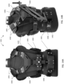
- FIG. 18 depicts an example pole mount 1308 according to one or more embodiments.
- the pole mount 1308 includes a first (top) shaft 1802 and a second (bottom) shaft 1804 that connect with each other using a joint 1806, such as a socket joint, a screw j oint, or any other such connecting j oint.
- the joint 1806 also couples with the connector 1512 of the mechanical arm 1302 to connect the pole mount 1308 with the mechanical arm 1302, and in turn, the body mount 1306.
- the pole mount 1308 includes a gimbal 1304.
- the gimbal 1304 is a mechanical mount with bearings to facilitate any weight mounted on it to have the center of mass in the center of the bearings. This allows the gimbal 1304 to move without rotating the mounted weighted item (e.g., the 3D scanner).
- the pole mount 1308 can also include a handle 1810 that allows the operator to move the gimbal 1304.
- the pole mount 1308 further includes a scanner adapter 1820 and a counterweight holder 1822.
- the scanner adapter 1820 facilitates mounting the 3D scanner 120 to the pole mount 1308.
- the counterweight holder 1822 is used to mount one or more items that counterbalance the weight of the 3D scanner 120 that is mounted on the pole mount 1308.
- one or more accessories of the 3D scanner are used as the counterweight.
- a battery pack, power adapter, digital data storage disks, communication hardware, or other such accessories can be used as a counterweight.
- other items non-accessories
- the counterweight facilitates stabilizing the 3D scanning.
- the counterweight holds the 3D scanner at a specific height depending on the spring preload (1514) of the mechanical arm 1302.
- the gimbal 1304 holds the weight of the 3D scanner 120 and facilitates the 3D scanner 120 to maintain orientation while it is being moved in the environment.
- mounting the 3D scanner 120 in this manner using the gimbal 1304 stabilizes the 3D scanner by preventing fast movement (shocks, shakes, etc.) of the 3D scanner 120, and hence improves (reduces deterioration of) the digital data captured by the 3D scanner 120 while being moved in the environment.
- the adapter 1822 connects the 3D scanner 120 to the pole mount 1308.
- the adapter 1822 can be configured for a specific type (model) of the 3D scanner 120.
- the adapter 1822 can facilitate connecting different types of 3D scanners 120.
- the adapter 1822 can include one or more electrical connections (e.g., ports) that facilitate the 3D scanner 120 to connect.
- the electrical connections can allow the 3D scanner to receive electrical power from the battery and/or power source that may be used as the counterweight and placed on the counterweight holder 1822 (or elsewhere).
- the electrical connections can facilitate the 3D scanner 120 to send/receive electric signals to/from one or more accessories placed on the counterweight holder 1822 (or elsewhere).
- the electric signals and/or electric power can be provided to the 3D scanner via one or more cables/wires that can be routed through or along the pole mount 1308.
- the pole mount 1308 is hollow, and the wires are routed through the hollow inside of the pole mount 1308.
- the pole mount 1308 includes one or more wire managers (e.g., clips) that facilitate guiding and holding the wires in place when routed on the outside of the pole mount 1308.
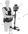
- FIGS. 19-20 depict additional views of the 3D scanner 120 being used in a portable manner by mounting the 3D scanner 120 to a pole mount 1308 for stabilization and support according to one or more aspects.
- the pole mount 1308 is connected to a body mount 1306 to improve weight distribution of the 3D scanner 120 to reduce the operator's discomfort.
- FIG. 21 depicts another example of a portable 3D scanning system according to one or more aspects.
- the 3D scanner 120 is mounted using the pole mount 1308 to a movable platform 1900.
- the moveable platform 1900 can be a vehicle, a drone, a trolley, etc.
- the moveable platform 1900 can be manual, autonomous, or semi-autonomous.
- the pole mount 1308 includes the gimbal 1304 to stabilize the 3D scanner 120 during the motion of the moveable platform 1900. It is understood that the pole mount 1308 can be coupled to the moveable platform at a different position (e.g., at the back of the platform) instead of the position shown.
- These computer program instructions may also be stored in a computer-readable medium that can direct a computer, other programmable data processing apparatus, or other devices to function in a particular manner, such that the instructions stored in the computer-readable medium produce an article of manufacture, including instructions which implement the function/act specified in the flowchart and/or block diagram block or blocks.
- the computer program instructions may also be loaded onto a computer, other programmable data processing apparatus, or other devices to cause a series of operational steps to be performed on the computer, other programmable apparatus, or other devices to produce a computer-implemented process such that the instructions which execute on the computer or other programmable apparatus provide processes for implementing the functions/acts specified in the flowchart and/or block diagram block or blocks.
Applications Claiming Priority (1)
| Application Number | Priority Date | Filing Date | Title |
|---|---|---|---|
| US202263328910P | 2022-04-08 | 2022-04-08 |
Publications (1)
| Publication Number | Publication Date |
|---|---|
| EP4258015A1 true EP4258015A1 (fr) | 2023-10-11 |
Family
ID=85979865
Family Applications (1)
| Application Number | Title | Priority Date | Filing Date |
|---|---|---|---|
| EP23166834.4A Pending EP4258015A1 (fr) | 2022-04-08 | 2023-04-05 | Système de support pour un appareil de balayage de coordonnées mobile |
Country Status (2)
| Country | Link |
|---|---|
| US (1) | US20230324556A1 (fr) |
| EP (1) | EP4258015A1 (fr) |
Cited By (1)
| Publication number | Priority date | Publication date | Assignee | Title |
|---|---|---|---|---|
| DE102022129177A1 (de) | 2022-11-04 | 2024-05-08 | Bayerische Motoren Werke Aktiengesellschaft | Erfassungsvorrichtung |
Citations (9)
| Publication number | Priority date | Publication date | Assignee | Title |
|---|---|---|---|---|
| US4158489A (en) * | 1976-07-19 | 1979-06-19 | Panavision, Incorporated | Body-mounted camera support apparatus |
| US20120069352A1 (en) | 2009-03-25 | 2012-03-22 | Faro Technologies, Inc. | Method for optically scanning and measuring a scene |
| US20170123066A1 (en) * | 2011-12-21 | 2017-05-04 | Robotic paradigm Systems LLC | Apparatus, Systems and Methods for Point Cloud Generation and Constantly Tracking Position |
| US20180149469A1 (en) * | 2015-12-30 | 2018-05-31 | Faro Technologies, Inc. | Registration of three-dimensional coordinates measured on interior and exterior portions of an object |
| WO2019018315A1 (fr) * | 2017-07-17 | 2019-01-24 | Kaarta, Inc. | Alignement de données de signal mesurées avec des données de localisation slam et utilisations associées |
| WO2020079394A1 (fr) * | 2018-10-15 | 2020-04-23 | Q-Bot Limited | Appareil capteur |
| US20200217666A1 (en) * | 2016-03-11 | 2020-07-09 | Kaarta, Inc. | Aligning measured signal data with slam localization data and uses thereof |
| DE102019120702A1 (de) * | 2019-07-31 | 2021-02-04 | Navvis Gmbh | Gestell für zumindest eine Scaneinrichtung und Raumerfassungsvorrichtung mit zumindest einer Scaneinrichtung |
| US20210136350A1 (en) * | 2019-11-01 | 2021-05-06 | Faro Technologies, Inc. | Using virtual landmarks during environment scanning |
-
2023
- 2023-04-05 EP EP23166834.4A patent/EP4258015A1/fr active Pending
- 2023-04-06 US US18/131,526 patent/US20230324556A1/en active Pending
Patent Citations (9)
| Publication number | Priority date | Publication date | Assignee | Title |
|---|---|---|---|---|
| US4158489A (en) * | 1976-07-19 | 1979-06-19 | Panavision, Incorporated | Body-mounted camera support apparatus |
| US20120069352A1 (en) | 2009-03-25 | 2012-03-22 | Faro Technologies, Inc. | Method for optically scanning and measuring a scene |
| US20170123066A1 (en) * | 2011-12-21 | 2017-05-04 | Robotic paradigm Systems LLC | Apparatus, Systems and Methods for Point Cloud Generation and Constantly Tracking Position |
| US20180149469A1 (en) * | 2015-12-30 | 2018-05-31 | Faro Technologies, Inc. | Registration of three-dimensional coordinates measured on interior and exterior portions of an object |
| US20200217666A1 (en) * | 2016-03-11 | 2020-07-09 | Kaarta, Inc. | Aligning measured signal data with slam localization data and uses thereof |
| WO2019018315A1 (fr) * | 2017-07-17 | 2019-01-24 | Kaarta, Inc. | Alignement de données de signal mesurées avec des données de localisation slam et utilisations associées |
| WO2020079394A1 (fr) * | 2018-10-15 | 2020-04-23 | Q-Bot Limited | Appareil capteur |
| DE102019120702A1 (de) * | 2019-07-31 | 2021-02-04 | Navvis Gmbh | Gestell für zumindest eine Scaneinrichtung und Raumerfassungsvorrichtung mit zumindest einer Scaneinrichtung |
| US20210136350A1 (en) * | 2019-11-01 | 2021-05-06 | Faro Technologies, Inc. | Using virtual landmarks during environment scanning |
Cited By (1)
| Publication number | Priority date | Publication date | Assignee | Title |
|---|---|---|---|---|
| DE102022129177A1 (de) | 2022-11-04 | 2024-05-08 | Bayerische Motoren Werke Aktiengesellschaft | Erfassungsvorrichtung |
Also Published As
| Publication number | Publication date |
|---|---|
| US20230324556A1 (en) | 2023-10-12 |
Similar Documents
| Publication | Publication Date | Title |
|---|---|---|
| EP3246660B1 (fr) | Système et procédé permettant de référencer un dispositif d'affichage par rapport à un instrument de surveillance | |
| US20130314688A1 (en) | Indoor surveying apparatus | |
| US10481265B2 (en) | Apparatus, systems and methods for point cloud generation and constantly tracking position | |
| US20170323458A1 (en) | Camera for Locating Hidden Objects | |
| EP3021078B1 (fr) | Système de relevé géodésique avec une caméra virtuelle | |
| US11557083B2 (en) | Photography-based 3D modeling system and method, and automatic 3D modeling apparatus and method | |
| US9349195B2 (en) | Apparatus and method for spatially referencing images | |
| US10767975B2 (en) | Data capture system for texture and geometry acquisition | |
| US20090262974A1 (en) | System and method for obtaining georeferenced mapping data | |
| TW201337306A (zh) | 用於建築工地之資訊擷取 | |
| EP4258015A1 (fr) | Système de support pour un appareil de balayage de coordonnées mobile | |
| US20220410401A1 (en) | Capturing environmental scans using automated transporter robot | |
| WO2018133077A1 (fr) | Système et procédé de rétroaction et d'acquisition d'informations environnementales pour fauteuil roulant intelligent | |
| Karam et al. | Integrating a low-cost mems imu into a laser-based slam for indoor mobile mapping | |
| Muffert et al. | The estimation of spatial positions by using an omnidirectional camera system | |
| CN208689169U (zh) | 一种基于单线激光雷达和标靶的室内三维测绘装置 | |
| US11936843B2 (en) | Generating textured three-dimensional meshes using two-dimensional scanner and panoramic camera | |
| US20230324558A1 (en) | Sensor field-of-view manipulation | |
| Masiero et al. | Aiding indoor photogrammetry with UWB sensors | |
| EP4258023A1 (fr) | Capture de représentation tridimensionnelle d'environnement à l'aide d'un dispositif mobile | |
| EP4332631A1 (fr) | Procédés d'optimisation globale pour scanners de coordonnées mobiles | |
| Rydell et al. | Chameleon v2: Improved imaging-inertial indoor navigation | |
| JP2021077127A (ja) | アイウェア装置を用いた管理システムおよび管理方法 | |
| Siddiqui et al. | Development of a Low-Cost Stationary Laser Scanning System for Generation of Building Information Models | |
| CA3102860C (fr) | Systeme et methode de modelisation 3d utilisant la photographie et appareil et methode de modelisation 3d automatique |
Legal Events
| Date | Code | Title | Description |
|---|---|---|---|
| PUAI | Public reference made under article 153(3) epc to a published international application that has entered the european phase |
Free format text: ORIGINAL CODE: 0009012 |
|
| STAA | Information on the status of an ep patent application or granted ep patent |
Free format text: STATUS: THE APPLICATION HAS BEEN PUBLISHED |
|
| AK | Designated contracting states |
Kind code of ref document: A1 Designated state(s): AL AT BE BG CH CY CZ DE DK EE ES FI FR GB GR HR HU IE IS IT LI LT LU LV MC ME MK MT NL NO PL PT RO RS SE SI SK SM TR |