EP4257996A1 - Parallel battery system and method of predicting remaining charge time thereof - Google Patents
Parallel battery system and method of predicting remaining charge time thereof Download PDFInfo
- Publication number
- EP4257996A1 EP4257996A1 EP22883793.6A EP22883793A EP4257996A1 EP 4257996 A1 EP4257996 A1 EP 4257996A1 EP 22883793 A EP22883793 A EP 22883793A EP 4257996 A1 EP4257996 A1 EP 4257996A1
- Authority
- EP
- European Patent Office
- Prior art keywords
- battery
- pack
- charge time
- remaining charge
- bms
- Prior art date
- Legal status (The legal status is an assumption and is not a legal conclusion. Google has not performed a legal analysis and makes no representation as to the accuracy of the status listed.)
- Granted
Links
Images


Classifications
-
- G—PHYSICS
- G01—MEASURING; TESTING
- G01R—MEASURING ELECTRIC VARIABLES; MEASURING MAGNETIC VARIABLES
- G01R31/00—Arrangements for testing electric properties; Arrangements for locating electric faults; Arrangements for electrical testing characterised by what is being tested not provided for elsewhere
- G01R31/36—Arrangements for testing, measuring or monitoring the electrical condition of accumulators or electric batteries, e.g. capacity or state of charge [SoC]
- G01R31/367—Software therefor, e.g. for battery testing using modelling or look-up tables
-
- H—ELECTRICITY
- H01—ELECTRIC ELEMENTS
- H01M—PROCESSES OR MEANS, e.g. BATTERIES, FOR THE DIRECT CONVERSION OF CHEMICAL ENERGY INTO ELECTRICAL ENERGY
- H01M10/00—Secondary cells; Manufacture thereof
- H01M10/42—Methods or arrangements for servicing or maintenance of secondary cells or secondary half-cells
- H01M10/48—Accumulators combined with arrangements for measuring, testing or indicating the condition of cells, e.g. the level or density of the electrolyte
- H01M10/482—Accumulators combined with arrangements for measuring, testing or indicating the condition of cells, e.g. the level or density of the electrolyte for several batteries or cells simultaneously or sequentially
-
- B—PERFORMING OPERATIONS; TRANSPORTING
- B60—VEHICLES IN GENERAL
- B60L—PROPULSION OF ELECTRICALLY-PROPELLED VEHICLES; SUPPLYING ELECTRIC POWER FOR AUXILIARY EQUIPMENT OF ELECTRICALLY-PROPELLED VEHICLES; ELECTRODYNAMIC BRAKE SYSTEMS FOR VEHICLES IN GENERAL; MAGNETIC SUSPENSION OR LEVITATION FOR VEHICLES; MONITORING OPERATING VARIABLES OF ELECTRICALLY-PROPELLED VEHICLES; ELECTRIC SAFETY DEVICES FOR ELECTRICALLY-PROPELLED VEHICLES
- B60L58/00—Methods or circuit arrangements for monitoring or controlling batteries or fuel cells, specially adapted for electric vehicles
- B60L58/10—Methods or circuit arrangements for monitoring or controlling batteries or fuel cells, specially adapted for electric vehicles for monitoring or controlling batteries
- B60L58/12—Methods or circuit arrangements for monitoring or controlling batteries or fuel cells, specially adapted for electric vehicles for monitoring or controlling batteries responding to state of charge [SoC]
-
- B—PERFORMING OPERATIONS; TRANSPORTING
- B60—VEHICLES IN GENERAL
- B60L—PROPULSION OF ELECTRICALLY-PROPELLED VEHICLES; SUPPLYING ELECTRIC POWER FOR AUXILIARY EQUIPMENT OF ELECTRICALLY-PROPELLED VEHICLES; ELECTRODYNAMIC BRAKE SYSTEMS FOR VEHICLES IN GENERAL; MAGNETIC SUSPENSION OR LEVITATION FOR VEHICLES; MONITORING OPERATING VARIABLES OF ELECTRICALLY-PROPELLED VEHICLES; ELECTRIC SAFETY DEVICES FOR ELECTRICALLY-PROPELLED VEHICLES
- B60L58/00—Methods or circuit arrangements for monitoring or controlling batteries or fuel cells, specially adapted for electric vehicles
- B60L58/10—Methods or circuit arrangements for monitoring or controlling batteries or fuel cells, specially adapted for electric vehicles for monitoring or controlling batteries
- B60L58/18—Methods or circuit arrangements for monitoring or controlling batteries or fuel cells, specially adapted for electric vehicles for monitoring or controlling batteries of two or more battery modules
-
- B—PERFORMING OPERATIONS; TRANSPORTING
- B60—VEHICLES IN GENERAL
- B60L—PROPULSION OF ELECTRICALLY-PROPELLED VEHICLES; SUPPLYING ELECTRIC POWER FOR AUXILIARY EQUIPMENT OF ELECTRICALLY-PROPELLED VEHICLES; ELECTRODYNAMIC BRAKE SYSTEMS FOR VEHICLES IN GENERAL; MAGNETIC SUSPENSION OR LEVITATION FOR VEHICLES; MONITORING OPERATING VARIABLES OF ELECTRICALLY-PROPELLED VEHICLES; ELECTRIC SAFETY DEVICES FOR ELECTRICALLY-PROPELLED VEHICLES
- B60L58/00—Methods or circuit arrangements for monitoring or controlling batteries or fuel cells, specially adapted for electric vehicles
- B60L58/10—Methods or circuit arrangements for monitoring or controlling batteries or fuel cells, specially adapted for electric vehicles for monitoring or controlling batteries
- B60L58/18—Methods or circuit arrangements for monitoring or controlling batteries or fuel cells, specially adapted for electric vehicles for monitoring or controlling batteries of two or more battery modules
- B60L58/22—Balancing the charge of battery modules
-
- G—PHYSICS
- G01—MEASURING; TESTING
- G01R—MEASURING ELECTRIC VARIABLES; MEASURING MAGNETIC VARIABLES
- G01R31/00—Arrangements for testing electric properties; Arrangements for locating electric faults; Arrangements for electrical testing characterised by what is being tested not provided for elsewhere
- G01R31/36—Arrangements for testing, measuring or monitoring the electrical condition of accumulators or electric batteries, e.g. capacity or state of charge [SoC]
- G01R31/3644—Constructional arrangements
- G01R31/3648—Constructional arrangements comprising digital calculation means, e.g. for performing an algorithm
-
- G—PHYSICS
- G01—MEASURING; TESTING
- G01R—MEASURING ELECTRIC VARIABLES; MEASURING MAGNETIC VARIABLES
- G01R31/00—Arrangements for testing electric properties; Arrangements for locating electric faults; Arrangements for electrical testing characterised by what is being tested not provided for elsewhere
- G01R31/36—Arrangements for testing, measuring or monitoring the electrical condition of accumulators or electric batteries, e.g. capacity or state of charge [SoC]
- G01R31/382—Arrangements for monitoring battery or accumulator variables, e.g. SoC
- G01R31/3842—Arrangements for monitoring battery or accumulator variables, e.g. SoC combining voltage and current measurements
-
- G—PHYSICS
- G01—MEASURING; TESTING
- G01R—MEASURING ELECTRIC VARIABLES; MEASURING MAGNETIC VARIABLES
- G01R31/00—Arrangements for testing electric properties; Arrangements for locating electric faults; Arrangements for electrical testing characterised by what is being tested not provided for elsewhere
- G01R31/36—Arrangements for testing, measuring or monitoring the electrical condition of accumulators or electric batteries, e.g. capacity or state of charge [SoC]
- G01R31/396—Acquisition or processing of data for testing or for monitoring individual cells or groups of cells within a battery
-
- H—ELECTRICITY
- H01—ELECTRIC ELEMENTS
- H01M—PROCESSES OR MEANS, e.g. BATTERIES, FOR THE DIRECT CONVERSION OF CHEMICAL ENERGY INTO ELECTRICAL ENERGY
- H01M10/00—Secondary cells; Manufacture thereof
- H01M10/42—Methods or arrangements for servicing or maintenance of secondary cells or secondary half-cells
- H01M10/44—Methods for charging or discharging
- H01M10/441—Methods for charging or discharging for several batteries or cells simultaneously or sequentially
-
- H—ELECTRICITY
- H01—ELECTRIC ELEMENTS
- H01M—PROCESSES OR MEANS, e.g. BATTERIES, FOR THE DIRECT CONVERSION OF CHEMICAL ENERGY INTO ELECTRICAL ENERGY
- H01M10/00—Secondary cells; Manufacture thereof
- H01M10/42—Methods or arrangements for servicing or maintenance of secondary cells or secondary half-cells
- H01M10/48—Accumulators combined with arrangements for measuring, testing or indicating the condition of cells, e.g. the level or density of the electrolyte
-
- H—ELECTRICITY
- H02—GENERATION; CONVERSION OR DISTRIBUTION OF ELECTRIC POWER
- H02J—ELECTRIC POWER NETWORKS; CIRCUIT ARRANGEMENTS OR SYSTEMS FOR SUPPLYING OR DISTRIBUTING ELECTRIC POWER; SYSTEMS FOR STORING ELECTRIC ENERGY
- H02J7/00—Circuit arrangements for charging or discharging batteries or for supplying loads from batteries
- H02J7/50—Circuit arrangements for charging or discharging batteries or for supplying loads from batteries acting upon multiple batteries simultaneously or sequentially
-
- H—ELECTRICITY
- H02—GENERATION; CONVERSION OR DISTRIBUTION OF ELECTRIC POWER
- H02J—ELECTRIC POWER NETWORKS; CIRCUIT ARRANGEMENTS OR SYSTEMS FOR SUPPLYING OR DISTRIBUTING ELECTRIC POWER; SYSTEMS FOR STORING ELECTRIC ENERGY
- H02J7/00—Circuit arrangements for charging or discharging batteries or for supplying loads from batteries
- H02J7/80—Circuit arrangements for charging or discharging batteries or for supplying loads from batteries including monitoring or indicating arrangements
-
- H—ELECTRICITY
- H02—GENERATION; CONVERSION OR DISTRIBUTION OF ELECTRIC POWER
- H02J—ELECTRIC POWER NETWORKS; CIRCUIT ARRANGEMENTS OR SYSTEMS FOR SUPPLYING OR DISTRIBUTING ELECTRIC POWER; SYSTEMS FOR STORING ELECTRIC ENERGY
- H02J7/00—Circuit arrangements for charging or discharging batteries or for supplying loads from batteries
- H02J7/80—Circuit arrangements for charging or discharging batteries or for supplying loads from batteries including monitoring or indicating arrangements
- H02J7/82—Control of state of charge [SOC]
-
- B—PERFORMING OPERATIONS; TRANSPORTING
- B60—VEHICLES IN GENERAL
- B60L—PROPULSION OF ELECTRICALLY-PROPELLED VEHICLES; SUPPLYING ELECTRIC POWER FOR AUXILIARY EQUIPMENT OF ELECTRICALLY-PROPELLED VEHICLES; ELECTRODYNAMIC BRAKE SYSTEMS FOR VEHICLES IN GENERAL; MAGNETIC SUSPENSION OR LEVITATION FOR VEHICLES; MONITORING OPERATING VARIABLES OF ELECTRICALLY-PROPELLED VEHICLES; ELECTRIC SAFETY DEVICES FOR ELECTRICALLY-PROPELLED VEHICLES
- B60L2240/00—Control parameters of input or output; Target parameters
- B60L2240/40—Drive Train control parameters
- B60L2240/54—Drive Train control parameters related to batteries
- B60L2240/545—Temperature
-
- B—PERFORMING OPERATIONS; TRANSPORTING
- B60—VEHICLES IN GENERAL
- B60L—PROPULSION OF ELECTRICALLY-PROPELLED VEHICLES; SUPPLYING ELECTRIC POWER FOR AUXILIARY EQUIPMENT OF ELECTRICALLY-PROPELLED VEHICLES; ELECTRODYNAMIC BRAKE SYSTEMS FOR VEHICLES IN GENERAL; MAGNETIC SUSPENSION OR LEVITATION FOR VEHICLES; MONITORING OPERATING VARIABLES OF ELECTRICALLY-PROPELLED VEHICLES; ELECTRIC SAFETY DEVICES FOR ELECTRICALLY-PROPELLED VEHICLES
- B60L2240/00—Control parameters of input or output; Target parameters
- B60L2240/40—Drive Train control parameters
- B60L2240/54—Drive Train control parameters related to batteries
- B60L2240/547—Voltage
-
- B—PERFORMING OPERATIONS; TRANSPORTING
- B60—VEHICLES IN GENERAL
- B60L—PROPULSION OF ELECTRICALLY-PROPELLED VEHICLES; SUPPLYING ELECTRIC POWER FOR AUXILIARY EQUIPMENT OF ELECTRICALLY-PROPELLED VEHICLES; ELECTRODYNAMIC BRAKE SYSTEMS FOR VEHICLES IN GENERAL; MAGNETIC SUSPENSION OR LEVITATION FOR VEHICLES; MONITORING OPERATING VARIABLES OF ELECTRICALLY-PROPELLED VEHICLES; ELECTRIC SAFETY DEVICES FOR ELECTRICALLY-PROPELLED VEHICLES
- B60L2240/00—Control parameters of input or output; Target parameters
- B60L2240/40—Drive Train control parameters
- B60L2240/54—Drive Train control parameters related to batteries
- B60L2240/549—Current
-
- H—ELECTRICITY
- H01—ELECTRIC ELEMENTS
- H01M—PROCESSES OR MEANS, e.g. BATTERIES, FOR THE DIRECT CONVERSION OF CHEMICAL ENERGY INTO ELECTRICAL ENERGY
- H01M10/00—Secondary cells; Manufacture thereof
- H01M10/42—Methods or arrangements for servicing or maintenance of secondary cells or secondary half-cells
- H01M10/425—Structural combination with electronic components, e.g. electronic circuits integrated to the outside of the casing
- H01M2010/4271—Battery management systems including electronic circuits, e.g. control of current or voltage to keep battery in healthy state, cell balancing
-
- Y—GENERAL TAGGING OF NEW TECHNOLOGICAL DEVELOPMENTS; GENERAL TAGGING OF CROSS-SECTIONAL TECHNOLOGIES SPANNING OVER SEVERAL SECTIONS OF THE IPC; TECHNICAL SUBJECTS COVERED BY FORMER USPC CROSS-REFERENCE ART COLLECTIONS [XRACs] AND DIGESTS
- Y02—TECHNOLOGIES OR APPLICATIONS FOR MITIGATION OR ADAPTATION AGAINST CLIMATE CHANGE
- Y02E—REDUCTION OF GREENHOUSE GAS [GHG] EMISSIONS, RELATED TO ENERGY GENERATION, TRANSMISSION OR DISTRIBUTION
- Y02E60/00—Enabling technologies; Technologies with a potential or indirect contribution to GHG emissions mitigation
- Y02E60/10—Energy storage using batteries
Definitions
- the present invention relates to a parallel battery system and a method of predicting remaining charge time of the parallel battery system.
- Electric vehicles receive power from a battery system, and the battery system includes a plurality of battery packs.
- the plurality of battery packs may be connected in parallel to each other or may be connected in series to each other or battery packs connected in parallel in a predetermined unit may be connected in series, according to the amount of power to be supplied to the battery system.
- the present invention has been made in an effort to provide a method for effectively predicting a remaining charge time according to a state of each of battery packs connected in parallel and a relay control in a battery system in which two or more battery packs are connected in parallel.
- An example embodiment of the present invention provides a method of predicting a remaining charge time to charge a plurality of battery packs connected in parallel up to a final target state of charge (SOC) includes: estimating, by a battery management system (BMS), an SOC of each of the plurality of battery packs; assigning, by the BMS, an ordering number in descending order of the SOC for the plurality of battery packs, determining, by the BMS, a connected pack group including a battery pack connected to a charging device with a closed relay, among the plurality of battery packs, and an available pack group including a battery pack with an opened relay and not connected to the charging device; predicting, by the BMS, a first remaining charge time required for a battery pack having the largest ordering number, among n battery packs constituting the connected pack group, to reach the final target SOC; predicting, by the BMS, m remaining charge times for m battery packs constituting the available pack group, and calculating a second remaining charge time by adding the m remaining charge times; and predicting, by the
- the estimating of the SOC of each of the plurality of battery pack may include estimating, by the BMS, the SOC of each of the plurality of battery packs based on a cell voltage of each of the plurality of battery cells received from a battery monitoring integrated circuit (BMIC) included in each of the plurality of battery packs, battery currents of the plurality of battery packs, and temperature information of the plurality of battery packs.
- BMIC battery monitoring integrated circuit
- the determining of the connected pack group and the available pack group may include determining, by the BMS, a battery pack having the estimated SOC value less than a reference SOC value, among the plurality of battery packs, as the connected pack group.
- the determining of the connected pack group and the available pack group may include the determining, by the BMS, a battery pack having the estimated SOC value equal to or greater than a reference SOC value, among the plurality of battery packs, as the available pack group.
- the calculating the second remaining charge time may include predicting, by the BMS, a remaining charge time of a first battery pack, excluding a battery pack having a largest ordering number, among the m battery packs, as a charge time required for an estimated SOC of each of the first battery packs to reach an estimated SOC of a second battery pack corresponding to a next ordering number.
- the calculating of the second remaining charge time may include predicting, by the BMS, a remaining charge time of a third battery pack having the largest ordering number, among the m battery packs, as a charge time required for an estimated SOC of the third battery pack to reach the final target SOC.
- Another example embodiment of the present invention provides a battery system including: a plurality of battery packs connected in parallel; and a battery management system (BMS) estimating an SOC value of each of the plurality of battery packs, assigning an ordering number in descending order of the SOC for the plurality of battery packs, determining, by the BMS, a connected pack group including a battery pack connected to a charging device with a closed relay, among the plurality of battery packs, and an available pack group including a battery pack with an opened relay and not connected to the charging device, predicting a first remaining charge time of the connected pack group and calculating a second remaining charge time of the available pack group, and predicting a final remaining charge time for charging the plurality of battery packs to a final target SOC by adding the first remaining charge time and the second remaining charge time.
- BMS battery management system
- the BMS may estimate the SOC of each of the plurality of battery packs based on a cell voltage of each of the plurality of battery cells received from a battery monitoring integrated circuit (BMIC) included in each of the plurality of battery packs, battery currents of the plurality of battery packs, and temperature information of the plurality of battery packs.
- BMIC battery monitoring integrated circuit
- the BMS may set a battery pack having the estimated SOC value less than a reference SOC value, among the plurality of battery packs, as the connected pack group.
- the BMS may set a battery pack having the estimated SOC value equal to or greater than a reference SOC value, among the plurality of battery packs, as the available pack group.
- the BMS may predict a time required for the battery pack having the largest ordering number, among the n battery packs constituting the connected pack group, to reach the final target SOC, as the first remaining charge time, wherein n is a natural number.
- the BMS may predict m remaining charge times for m battery packs constituting the available pack group and calculate a second remaining charge time by adding the m remaining charge times, wherein m is a natural number.
- the BMS may predict a charge time required for an estimated SOC of a first battery pack excluding the battery pack having the largest ordering number, among the m battery packs, to reach an estimated SOC of a second battery pack corresponding to a next ordering number, as a remaining charge time of the first battery pack.
- the BMS may predict a remaining charge time of a third battery pack having the largest ordering number, among the m battery packs, as a charge time required for the estimated SOC of the third battery pack to reach the final target SOC and may calculate the second remaining charge time by adding the remaining charge time of the first battery pack and the remaining charge time of the third battery pack.
- a remaining charge time may be effectively predicted by providing an effective method of predicting a remaining charge time according to a state of each battery pack connected in parallel and a relay control.
- a program implemented as a set of instructions embodying a control algorithm necessary to control another configuration may be installed in a configuration for controlling another configuration under a specific control condition among configurations according to an example embodiment.
- the control configuration may process input data and stored data according to an installed program to generate output data.
- the control configuration may include a non-volatile memory to store a program and a memory to store data.
- FIG. 1 is a diagram illustrating a configuration of a battery system and an external device connected to the battery system according to an example embodiment.
- the battery system 1 includes a plurality of battery packs 10 to 50, a battery management system (BMS) 60, and a main relay 70.
- FIG. 1 shows that the number of the plurality of battery packs 10 to 50 is five, but the present invention is not limited thereto, and the battery system 1 may include two or more battery packs.
- the battery management system 60 is referred to as a BMS.
- An external device 2 may include a load, such as an inverter and a converter, and a charging device.
- a load such as an inverter and a converter
- One end of the main relay 70 is connected to the battery system 1, and the other end of the main relay 70 is connected to at least one component of the external device 2.
- the plurality of battery packs 10 to 50 may be connected in parallel to each other, and each of the plurality of battery packs 10 to 50 may be connected in parallel to the external device 2 through the main relay 70.
- Each of the plurality of battery packs 10 to 50 includes a plurality of corresponding battery cells (e.g., 11 to 15) among the entire battery cells 11 to 15, 21 to 25, 31 to 25, 41 to 45, and 51 to 55, corresponding relays (e.g., 101) among the plurality of relays 101, 201, 301, 401, and 501, and corresponding pack battery monitoring integrated circuits (e.g., 102) among the plurality of pack battery monitoring integrated circuits 102, 202, 302, 402, and 502.
- the battery monitoring integrated circuit is referred to as a BMIC.
- a plurality of pack BMICs 102 to 502 are connected to a plurality of battery cells 11 to 15, 21 to 25, 31 to 25, 41 to 45, and 51 to 55, for example, 11 to 15, and obtain information on a cell voltage of each of the plurality of battery cells 11 to 15, 21 to 25, 31 to 25, 41 to 45, and 51 to 55, a battery current of the battery packs 10 to 50, a temperature of the battery packs 10 to 50, etc.
- the BMS 60 may control charging and discharging of the plurality of battery packs 10 to 50 based on the battery pack voltage, battery pack current, battery pack temperature, etc., received from the plurality of pack BMICs 102 to 502, and may control a cell balancing operation on the plurality of battery cells 11 to 15, 21 to 25, 31 to 35, 41 to 45, and 51 to 55.
- the BMS 60 may transmit a control signal for charging/discharging, a control signal for controlling a cell balancing operation, and the like to the plurality of pack BMICs 102 to 502 and the main relay 70.
- Each of the plurality of pack BMICs 102 to 502 may control opening and closing of a corresponding relay among the plurality of relays 101, 201, 301, 401, and 501 based on a corresponding control signal received from the BMS 60, and may control a cell balancing operation on each of the plurality of corresponding battery cells among the plurality of battery cells 11 to 15, 21 to 25, 31 to 35, 41 to 45, and 51 to 55.
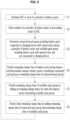
- FIG. 2 is a flowchart illustrating a method of predicting a remaining charge time according to an example embodiment.
- the BMS 60 estimates a state of charge (SOC) of each of the plurality of battery packs 10 to 50 (S1).
- the BMS 60 may estimate a charge state and the degree of a battery degradation of each battery pack 10 to 50 based on a battery cell voltage of each of the plurality of battery cells 11 to 15, 21 to 25, 31 to 35, 41 to 45, and 51 to 55 received from the plurality of pack BMICs 102 to 502, a battery pack current of the plurality of battery packs 10 to 50, and a battery pack temperature of the plurality of battery packs 10 to 50.
- SOC state of charge
- SOH state of health
- the BMS 60 may estimate an SOC of each of the plurality of battery cells 11 to 15, 21 to 25, 31 to 35, 41 to 45, and 51 to 55 based on the information on the cell voltage of the plurality of battery cells 11 to 15, 21 to 25, 31 to 35, 41 to 45, and 51 to 55 and the battery current and temperature of the plurality of battery packs 10 to 50 received from the plurality of pack BMICs 102 to 502, and may estimate an SOC of each of the plurality of battery packs 10 to 50.
- the BMS 60 may derive a representative SOC based on the SOC of a plurality of battery cells (e.g., 11 to 15) and estimate it as an SOC of the battery pack (e.g., 10).
- a method of deriving the representative SOC a method of deriving a maximum value, a minimum value, an average value, and the like may be used.
- a maximum value among the SOCs of the plurality of battery cells e.g., 11 to 15
- a maximum value among the SOCs of the plurality of battery cells e.g., 11 to 15
- the method of estimating the SOC of each of the plurality of battery cells 11 to 15, 21 to 25, 31 to 35, 41 to 45, and 51 to 55 may be one of various know methods, such as a current integration method, an SOC estimation method based on a battery equivalent circuit model, and a method of mixing the current integration method and an SOC estimation method based on an equivalent circuit model using a Kalman filter.
- the BMS 60 orders numbers in descending order of the SOC for the plurality of battery packs 10 to 50 (S2).
- FIG. 3 is a diagram schematically illustrating a plurality of battery packs and a state of charge of each battery pack to explain a method of predicting a remaining charge time of FIG. 2 .
- the BMS 60 assigns an index number to each of the plurality of battery packs 10 to 50 to distinguish the plurality of battery packs 10 to 50 from each other. For example, in FIG. 3(a) , the plurality of battery packs 10 to 50 are assigned with index numbers of 1, 2, 3, 4, and 5 sequentially from the left.
- the SOC estimated in the plurality of battery packs 10 to 50 may be schematically represented as a width of a shaded area inside each battery pack.
- the arrangement of the index numbers according to the SOC of the plurality of battery packs 10 to 50 are 5, 1, 3, 2, and 4 in descending order.
- the BMS 60 may arrange the plurality of battery packs 10 to 50 in descending order of the SOC and assign an ordering number to the plurality of battery packs 10 to 50 through step S2.
- the ordering number is a number assigned to each of the plurality of battery packs 10 to 50 when arranging the plurality of battery packs 10 to 50 in descending order of the SOC.
- the BMS 60 when the BMS 60 arranges the plurality of battery packs 10 to 50 in the descending order of the SOC, they are arranged in the order of index numbers 5, 1, 3, 2, and 4.
- the BMS 60 may sequentially assign an ordering number to the plurality of arranged battery packs 10 to 50. Accordingly, the ordering numbers of the plurality of battery packs 10 to 50 are numbered 1, 2, 3, 4, and 5 sequentially from the left. Also, in FIG. 3(b) , the index numbers of the plurality of battery packs 10 to 50 are 5, 1, 3, 2, and 4 in order from the left.
- the BMS 60 may determine a final target SOC of the plurality of battery packs 10 to 50. For example, the BMS 60 may determine the final target SOC to be 95% of the SOC of a fully charged battery pack.
- the BMS 60 may determine a connected pack group including a battery pack connected to the charging device with the relay 101 to 501 closed, among the plurality of battery packs 10 to 50 and an available pack group including a battery pack not connected to the charging device with the relays 101 to 501 opened (S3).
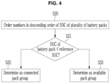
- FIG. 4 is a flowchart illustrating a method of predicting a remaining charge time according to an example embodiment.
- the BMS 60 orders the numbers in descending order of the SOC of the plurality of battery packs 10 to 50 (S20) and determines whether the SOC of each battery pack 10 to 50 is less than a reference SOC (S31). As a result of the determination in step S31, a battery pack having an SOC less than the reference SOC is determined as a connected pack group (S32). As a result of the determination in step S31, a battery pack having an SOC equal to or greater than the reference SOC is determined as an available pack group (S33).
- the reference SOC may be predetermined as initial information.
- the BMS 60 may determine the battery packs 50, 10, and 30 with ordering numbers 1, 2, and 3 as a connected pack group, and the battery packs 20 and 40 with ordering numbers 4 and 5 as an available pack group.
- the relays 501, 101, and 301 of the battery packs 50, 10 and 30 constituting the connected pack group are controlled to a closed state by a control signal generated by the BMS 60.
- the relays 201 and 401 of the battery packs 20 and 40 constituting the available pack group are controlled to an open state by a control signal generated by the BMS 60.
- a control signal for controlling the opening or closing of the relay is generated in the BMS 60 and transmitted to the corresponding pack BMIC 102 to 502 of the battery pack, and the pack BMIC 102 to 502 may generate a relay driving control signal according to a control signal and supply the generated driving control signal to each relay 101 to 501.
- the BMS 60 To predict a final remaining charge time of the battery system 1, the BMS 60 derives a remaining charge time of the connected pack group and a remaining charge time of the available pack group.
- the BMS 60 may predict a remaining charge time for the connected pack group and a remaining charge time for the available pack group.
- the BMS 60 may estimate a remaining charge time of the battery pack unit by dividing remaining energy of the battery pack by power that may be supplied from the charging device.
- the remaining energy of the battery pack is a difference between the energy corresponding to a charging target SOC and the energy of a currently estimated SOC of the battery pack.
- the BMS 60 may store the energy of the battery pack corresponding to each SOC as a table. This is expressed by [Equation 1] below.
- CRT Remainig Energy kWh Available Power kW
- the charging target SOC for the BMS 60 to select the remaining charge time for each battery pack may be differently determined based on whether the group to which each battery pack 10 to 50 belongs is a connected pack group or an available pack group.
- the BMS 60 predicts a remaining charge time (e.g., c) of a battery pack having the largest ordering number, among n battery packs (e.g., 50, 10, and 30) constituting the connected pack group, as a remaining charge time of the connected pack group (S4).
- the BMS 60 may predict an expected time required for a battery pack having the highest SOC, among at least one battery pack belonging to the connected pack group, to reach the final target SOC as a remaining charge time of the connected pack group.
- the BMS 60 assumes that the final target SOC (e.g., SOC 95%) is the charging target SOC in predicting the remaining charge time of the battery pack belonging to the connected pack group.
- the final target SOC e.g., SOC 95%) is the charging target SOC in predicting the remaining charge time of the battery pack belonging to the connected pack group.
- the BMS 60 may predict a remaining charge time (c) for the battery pack 30 having the highest SOC, among the three battery packs 50, 10, and 30 included in the connected pack group, to reach the final target SOC, as the remaining charge time of the connected pack group.
- the battery packs 50, 10, and 30 are connected in parallel to the charging device, 1/3 of charging power per one battery pack may be supplied. After charging of the battery packs 50, 10, and 30 is started, charging may be terminated when any one of the battery packs 50, 10, and 30 connected in parallel to the charging device reaches the target SOC.
- the use of the remaining charge time (c) of the battery pack 30 as a representative value as the remaining charge time of the connected pack group is because the battery pack 30, among the battery packs 50, 10, and 30 connected in parallel to the charging device, has the highest SOC before charging, so that the battery pack 30 may first reach the target SOC.
- the BMS 60 predicts the remaining charge time of the available pack group by adding the m remaining charge times for each of the m battery packs (e.g., 20 and 40) constituting the available pack group (S5).
- the BMS 60 may predict the remaining charge time for each of the at least one battery pack belonging to the available pack group and may predict the remaining charge time for the available pack group by adding up the predicted remaining charge times.
- the BMS 60 may predict the remaining charge time of the available pack group by adding up the remaining charge time (d) of the battery pack 20 included in the available pack group and the remaining charge time (e) of the battery pack 40.
- the BMS 60 may predict a charge time required for the estimated SOC of the battery pack 20 to reach the estimated SOC (charging target SOC) of the battery pack 40 corresponding to a next ordering number as the remaining charge time (d).
- the BMS 60 may predict the charge time required for the estimated SOC of the battery pack 40 having the largest ordering number of the available pack group to reach the final target SOC (charging target SOC) as the remaining charge time (e).
- the BMS 60 in predicting the remaining charge time of the battery pack having the largest ordering number, among the battery packs belonging to the available pack group, the BMS 60 assumes the estimated SOC of the battery pack corresponding to the next ordering number as the charging target SOC. In addition, in predicting the remaining charge time of the battery pack having the largest ordering number, among the battery packs belonging to the available pack group, the BMS 60 assumes that the final target SOC (e.g., SOC 95%) is the charging target SOC.
- the final target SOC e.g., SOC 95%) is the charging target SOC.
- the sum (d+e) of the remaining charge times (d, e) of each of the battery packs 20 and 40 constituting the available pack group is the same as the charge time estimated to reach the final target SOC value based on the estimated SOC value of the battery pack 20 having the smallest ordering number, among the battery packs 20 and 40 constituting the available pack group.
- the remaining charge time of the connected pack group - battery packs 50, 10, and 30 - that may be connected to the charging device and the remaining charge time of the usable available pack group - battery packs 20 and 40 - may be predicted in another way.
- the BMS 60 predicts the final remaining charge time by adding the remaining charge time of the connected pack group and the remaining charge time of the available pack group (S6).
- a method in which the BMS 60 predicts the final remaining charge time of the battery system 1 may be expressed by Equation 2 below.
- CRT is the remaining charge time
- ConnP is a connected battery pack group
- AvailP is an available battery pack.
- the BMS 60 may repeat steps S1 to S6 again.
Landscapes
- Engineering & Computer Science (AREA)
- Power Engineering (AREA)
- General Physics & Mathematics (AREA)
- Physics & Mathematics (AREA)
- Chemical Kinetics & Catalysis (AREA)
- Electrochemistry (AREA)
- General Chemical & Material Sciences (AREA)
- Chemical & Material Sciences (AREA)
- Manufacturing & Machinery (AREA)
- Life Sciences & Earth Sciences (AREA)
- Sustainable Development (AREA)
- Sustainable Energy (AREA)
- Transportation (AREA)
- Mechanical Engineering (AREA)
- Charge And Discharge Circuits For Batteries Or The Like (AREA)
- Secondary Cells (AREA)
- Tests Of Electric Status Of Batteries (AREA)
Abstract
Description
- This application claims benefit of priority to
Korean Patent Application No. 10-2021-0138650 filed on October 18, 2021 - The present invention relates to a parallel battery system and a method of predicting remaining charge time of the parallel battery system.
- Electric vehicles receive power from a battery system, and the battery system includes a plurality of battery packs. The plurality of battery packs may be connected in parallel to each other or may be connected in series to each other or battery packs connected in parallel in a predetermined unit may be connected in series, according to the amount of power to be supplied to the battery system.
- In the case of a battery system in which two or more battery packs have a parallel structure, compared with a battery system in which two or more battery packs have a series structure, there are matters to be considered to predict a remaining charge time. The reason is because each of the plurality of battery packs connected in parallel involves a relay control. An effective technology for predicting a remaining charge time according to a state of each battery pack connected in parallel and relay control is required.
- The present invention has been made in an effort to provide a method for effectively predicting a remaining charge time according to a state of each of battery packs connected in parallel and a relay control in a battery system in which two or more battery packs are connected in parallel.
- An example embodiment of the present invention provides a method of predicting a remaining charge time to charge a plurality of battery packs connected in parallel up to a final target state of charge (SOC) includes: estimating, by a battery management system (BMS), an SOC of each of the plurality of battery packs; assigning, by the BMS, an ordering number in descending order of the SOC for the plurality of battery packs, determining, by the BMS, a connected pack group including a battery pack connected to a charging device with a closed relay, among the plurality of battery packs, and an available pack group including a battery pack with an opened relay and not connected to the charging device; predicting, by the BMS, a first remaining charge time required for a battery pack having the largest ordering number, among n battery packs constituting the connected pack group, to reach the final target SOC; predicting, by the BMS, m remaining charge times for m battery packs constituting the available pack group, and calculating a second remaining charge time by adding the m remaining charge times; and predicting, by the BMS, a final remaining charge time by adding the first remaining charge time and the second remaining charge time, wherein n and m are natural numbers.
- The estimating of the SOC of each of the plurality of battery pack may include estimating, by the BMS, the SOC of each of the plurality of battery packs based on a cell voltage of each of the plurality of battery cells received from a battery monitoring integrated circuit (BMIC) included in each of the plurality of battery packs, battery currents of the plurality of battery packs, and temperature information of the plurality of battery packs.
- The determining of the connected pack group and the available pack group may include determining, by the BMS, a battery pack having the estimated SOC value less than a reference SOC value, among the plurality of battery packs, as the connected pack group.
- The determining of the connected pack group and the available pack group may include the determining, by the BMS, a battery pack having the estimated SOC value equal to or greater than a reference SOC value, among the plurality of battery packs, as the available pack group.
- The calculating the second remaining charge time may include predicting, by the BMS, a remaining charge time of a first battery pack, excluding a battery pack having a largest ordering number, among the m battery packs, as a charge time required for an estimated SOC of each of the first battery packs to reach an estimated SOC of a second battery pack corresponding to a next ordering number.
- The calculating of the second remaining charge time may include predicting, by the BMS, a remaining charge time of a third battery pack having the largest ordering number, among the m battery packs, as a charge time required for an estimated SOC of the third battery pack to reach the final target SOC.
- Another example embodiment of the present invention provides a battery system including: a plurality of battery packs connected in parallel; and a battery management system (BMS) estimating an SOC value of each of the plurality of battery packs, assigning an ordering number in descending order of the SOC for the plurality of battery packs, determining, by the BMS, a connected pack group including a battery pack connected to a charging device with a closed relay, among the plurality of battery packs, and an available pack group including a battery pack with an opened relay and not connected to the charging device, predicting a first remaining charge time of the connected pack group and calculating a second remaining charge time of the available pack group, and predicting a final remaining charge time for charging the plurality of battery packs to a final target SOC by adding the first remaining charge time and the second remaining charge time.
- The BMS may estimate the SOC of each of the plurality of battery packs based on a cell voltage of each of the plurality of battery cells received from a battery monitoring integrated circuit (BMIC) included in each of the plurality of battery packs, battery currents of the plurality of battery packs, and temperature information of the plurality of battery packs.
- The BMS may set a battery pack having the estimated SOC value less than a reference SOC value, among the plurality of battery packs, as the connected pack group.
- The BMS may set a battery pack having the estimated SOC value equal to or greater than a reference SOC value, among the plurality of battery packs, as the available pack group.
- The BMS may predict a time required for the battery pack having the largest ordering number, among the n battery packs constituting the connected pack group, to reach the final target SOC, as the first remaining charge time, wherein n is a natural number.
- The BMS may predict m remaining charge times for m battery packs constituting the available pack group and calculate a second remaining charge time by adding the m remaining charge times, wherein m is a natural number.
- The BMS may predict a charge time required for an estimated SOC of a first battery pack excluding the battery pack having the largest ordering number, among the m battery packs, to reach an estimated SOC of a second battery pack corresponding to a next ordering number, as a remaining charge time of the first battery pack.
- The BMS may predict a remaining charge time of a third battery pack having the largest ordering number, among the m battery packs, as a charge time required for the estimated SOC of the third battery pack to reach the final target SOC and may calculate the second remaining charge time by adding the remaining charge time of the first battery pack and the remaining charge time of the third battery pack.
- In a battery system in which two or more battery packs are connected in parallel, a remaining charge time may be effectively predicted by providing an effective method of predicting a remaining charge time according to a state of each battery pack connected in parallel and a relay control.
-
-
FIG. 1 is a diagram illustrating a configuration of a battery system and an external device connected to the battery system according to an example embodiment. -
FIG. 2 is a flowchart illustrating a method of predicting a remaining charge time according to an example embodiment. -
FIG. 3 is a diagram schematically illustrating a plurality of battery packs and a charge state of each battery pack to explain a method of predicting a remaining charge time ofFIG. 2 . -
FIG. 4 is a flowchart illustrating a method of predicting a remaining charge time according to an example embodiment. - Hereinafter, example embodiments of the present invention will be described with reference to the accompanying drawings, in which like numbers refer to like elements throughout although the example embodiments are different, and a redundant description thereof is omitted. In the following description, usage of suffixes such as "module," "part," or "unit" used for referring to elements is given merely to facilitate explanation of the present invention, without having any significant meaning by itself. In describing the present invention, if a detailed explanation for a related known function or construction is considered to unnecessarily divert the gist of the present invention, such explanation has been omitted but would be understood by those skilled in the art. The accompanying drawings of the present invention aim to facilitate understanding of the present invention and should not be construed as limited to the accompanying drawings. Also, the present invention is not limited to a specific disclosed form, but includes all modifications, equivalents, and substitutions without departing from the scope and spirit of the present invention.
- It will be understood that, although the terms first, second, etc. may be used herein to describe various elements, these elements should not be limited by these terms. These terms are only used to distinguish one element from another
- It will be further understood that the terms "comprise" or "have" used in this specification, specify the presence of stated features, steps, operations, components, parts, or a combination thereof, but do not preclude the presence or addition of one or more other features, numerals, steps, operations, components, parts, or a combination thereof.
- A program implemented as a set of instructions embodying a control algorithm necessary to control another configuration may be installed in a configuration for controlling another configuration under a specific control condition among configurations according to an example embodiment. The control configuration may process input data and stored data according to an installed program to generate output data. The control configuration may include a non-volatile memory to store a program and a memory to store data.
-
FIG. 1 is a diagram illustrating a configuration of a battery system and an external device connected to the battery system according to an example embodiment. - The
battery system 1 includes a plurality ofbattery packs 10 to 50, a battery management system (BMS) 60, and amain relay 70.FIG. 1 shows that the number of the plurality ofbattery packs 10 to 50 is five, but the present invention is not limited thereto, and thebattery system 1 may include two or more battery packs. Hereinafter, thebattery management system 60 is referred to as a BMS. - An
external device 2 may include a load, such as an inverter and a converter, and a charging device. One end of themain relay 70 is connected to thebattery system 1, and the other end of themain relay 70 is connected to at least one component of theexternal device 2. - The plurality of
battery packs 10 to 50 may be connected in parallel to each other, and each of the plurality ofbattery packs 10 to 50 may be connected in parallel to theexternal device 2 through themain relay 70. Each of the plurality ofbattery packs 10 to 50 includes a plurality of corresponding battery cells (e.g., 11 to 15) among the entire battery cells 11 to 15, 21 to 25, 31 to 25, 41 to 45, and 51 to 55, corresponding relays (e.g., 101) among the plurality ofrelays - A plurality of pack BMICs 102 to 502 are connected to a plurality of battery cells 11 to 15, 21 to 25, 31 to 25, 41 to 45, and 51 to 55, for example, 11 to 15, and obtain information on a cell voltage of each of the plurality of battery cells 11 to 15, 21 to 25, 31 to 25, 41 to 45, and 51 to 55, a battery current of the
battery packs 10 to 50, a temperature of thebattery packs 10 to 50, etc. - The BMS 60 may control charging and discharging of the plurality of
battery packs 10 to 50 based on the battery pack voltage, battery pack current, battery pack temperature, etc., received from the plurality of pack BMICs 102 to 502, and may control a cell balancing operation on the plurality of battery cells 11 to 15, 21 to 25, 31 to 35, 41 to 45, and 51 to 55. - The BMS 60 may transmit a control signal for charging/discharging, a control signal for controlling a cell balancing operation, and the like to the plurality of pack BMICs 102 to 502 and the
main relay 70. Each of the plurality of pack BMICs 102 to 502 may control opening and closing of a corresponding relay among the plurality ofrelays BMS 60, and may control a cell balancing operation on each of the plurality of corresponding battery cells among the plurality of battery cells 11 to 15, 21 to 25, 31 to 35, 41 to 45, and 51 to 55. - Hereinafter, a method of predicting a remaining charge time of the
battery system 1 by theBMS 60 by receiving a battery pack voltage, a battery pack current, a battery pack temperature, and whether each of the plurality ofrelays 101 to 501 is opened or closed from the plurality of pack BMICs 102 to 502 will be described with reference toFIG. 2 . -
FIG. 2 is a flowchart illustrating a method of predicting a remaining charge time according to an example embodiment. - The
BMS 60 estimates a state of charge (SOC) of each of the plurality ofbattery packs 10 to 50 (S1). TheBMS 60 may estimate a charge state and the degree of a battery degradation of eachbattery pack 10 to 50 based on a battery cell voltage of each of the plurality of battery cells 11 to 15, 21 to 25, 31 to 35, 41 to 45, and 51 to 55 received from the plurality of pack BMICs 102 to 502, a battery pack current of the plurality ofbattery packs 10 to 50, and a battery pack temperature of the plurality ofbattery packs 10 to 50. Hereinafter, a charge state of the battery is referred to as a state of charge (SOC), and the degree of a degradation of the battery is referred to as a state of health (SOH) hereinafter. - The
BMS 60 may estimate an SOC of each of the plurality of battery cells 11 to 15, 21 to 25, 31 to 35, 41 to 45, and 51 to 55 based on the information on the cell voltage of the plurality of battery cells 11 to 15, 21 to 25, 31 to 35, 41 to 45, and 51 to 55 and the battery current and temperature of the plurality ofbattery packs 10 to 50 received from the plurality of pack BMICs 102 to 502, and may estimate an SOC of each of the plurality ofbattery packs 10 to 50. - The
BMS 60 may derive a representative SOC based on the SOC of a plurality of battery cells (e.g., 11 to 15) and estimate it as an SOC of the battery pack (e.g., 10). As a method of deriving the representative SOC, a method of deriving a maximum value, a minimum value, an average value, and the like may be used. When the battery pack (e.g., 10) is charged, a maximum value among the SOCs of the plurality of battery cells (e.g., 11 to 15) may be the representative SOC. The method of estimating the SOC of each of the plurality of battery cells 11 to 15, 21 to 25, 31 to 35, 41 to 45, and 51 to 55 may be one of various know methods, such as a current integration method, an SOC estimation method based on a battery equivalent circuit model, and a method of mixing the current integration method and an SOC estimation method based on an equivalent circuit model using a Kalman filter. - The
BMS 60 orders numbers in descending order of the SOC for the plurality of battery packs 10 to 50 (S2). -
FIG. 3 is a diagram schematically illustrating a plurality of battery packs and a state of charge of each battery pack to explain a method of predicting a remaining charge time ofFIG. 2 . - Before ordering, the
BMS 60 assigns an index number to each of the plurality of battery packs 10 to 50 to distinguish the plurality of battery packs 10 to 50 from each other. For example, inFIG. 3(a) , the plurality of battery packs 10 to 50 are assigned with index numbers of 1, 2, 3, 4, and 5 sequentially from the left. - In
FIG. 3 , the SOC estimated in the plurality of battery packs 10 to 50 may be schematically represented as a width of a shaded area inside each battery pack. InFIG. 3(a) , the arrangement of the index numbers according to the SOC of the plurality of battery packs 10 to 50 are 5, 1, 3, 2, and 4 in descending order. - The
BMS 60 may arrange the plurality of battery packs 10 to 50 in descending order of the SOC and assign an ordering number to the plurality of battery packs 10 to 50 through step S2. The ordering number is a number assigned to each of the plurality of battery packs 10 to 50 when arranging the plurality of battery packs 10 to 50 in descending order of the SOC. - For example, in
FIG. 3(b) , when theBMS 60 arranges the plurality of battery packs 10 to 50 in the descending order of the SOC, they are arranged in the order ofindex numbers BMS 60 may sequentially assign an ordering number to the plurality of arranged battery packs 10 to 50. Accordingly, the ordering numbers of the plurality of battery packs 10 to 50 are numbered 1, 2, 3, 4, and 5 sequentially from the left. Also, inFIG. 3(b) , the index numbers of the plurality of battery packs 10 to 50 are 5, 1, 3, 2, and 4 in order from the left. - The
BMS 60 may determine a final target SOC of the plurality of battery packs 10 to 50. For example, theBMS 60 may determine the final target SOC to be 95% of the SOC of a fully charged battery pack. - The
BMS 60 may determine a connected pack group including a battery pack connected to the charging device with therelay 101 to 501 closed, among the plurality of battery packs 10 to 50 and an available pack group including a battery pack not connected to the charging device with therelays 101 to 501 opened (S3). - Hereinafter, an operation in which the
BMS 60 determines a connected pack group and an available pack group may be described with reference toFIG. 4 . -
FIG. 4 is a flowchart illustrating a method of predicting a remaining charge time according to an example embodiment. - The
BMS 60 orders the numbers in descending order of the SOC of the plurality of battery packs 10 to 50 (S20) and determines whether the SOC of eachbattery pack 10 to 50 is less than a reference SOC (S31). As a result of the determination in step S31, a battery pack having an SOC less than the reference SOC is determined as a connected pack group (S32). As a result of the determination in step S31, a battery pack having an SOC equal to or greater than the reference SOC is determined as an available pack group (S33). Here, the reference SOC may be predetermined as initial information. - In the example of
FIG. 3 , theBMS 60 may determine the battery packs 50, 10, and 30 with orderingnumbers numbers - The
relays BMS 60. Therelays BMS 60. A control signal for controlling the opening or closing of the relay is generated in theBMS 60 and transmitted to the corresponding pack BMIC 102 to 502 of the battery pack, and the pack BMIC 102 to 502 may generate a relay driving control signal according to a control signal and supply the generated driving control signal to eachrelay 101 to 501. - To predict a final remaining charge time of the
battery system 1, theBMS 60 derives a remaining charge time of the connected pack group and a remaining charge time of the available pack group. - Hereinafter, a remaining charge time estimating steps S4 to S6 will be described based on the example of
FIG. 3 . - The
BMS 60 may predict a remaining charge time for the connected pack group and a remaining charge time for the available pack group. - The
BMS 60 may estimate a remaining charge time of the battery pack unit by dividing remaining energy of the battery pack by power that may be supplied from the charging device. The remaining energy of the battery pack is a difference between the energy corresponding to a charging target SOC and the energy of a currently estimated SOC of the battery pack. TheBMS 60 may store the energy of the battery pack corresponding to each SOC as a table. This is expressed by [Equation 1] below.
- The charging target SOC for the
BMS 60 to select the remaining charge time for each battery pack may be differently determined based on whether the group to which eachbattery pack 10 to 50 belongs is a connected pack group or an available pack group. - The
BMS 60 predicts a remaining charge time (e.g., c) of a battery pack having the largest ordering number, among n battery packs (e.g., 50, 10, and 30) constituting the connected pack group, as a remaining charge time of the connected pack group (S4). Here, n is a natural number. In the example ofFIG. 3 , n=3. - The
BMS 60 may predict an expected time required for a battery pack having the highest SOC, among at least one battery pack belonging to the connected pack group, to reach the final target SOC as a remaining charge time of the connected pack group. - In other words, the
BMS 60 assumes that the final target SOC (e.g., SOC 95%) is the charging target SOC in predicting the remaining charge time of the battery pack belonging to the connected pack group. - Referring to
FIG. 3 , theBMS 60 may predict a remaining charge time (c) for thebattery pack 30 having the highest SOC, among the threebattery packs - Since the battery packs 50, 10, and 30 are connected in parallel to the charging device, 1/3 of charging power per one battery pack may be supplied. After charging of the battery packs 50, 10, and 30 is started, charging may be terminated when any one of the battery packs 50, 10, and 30 connected in parallel to the charging device reaches the target SOC. The use of the remaining charge time (c) of the
battery pack 30 as a representative value as the remaining charge time of the connected pack group is because thebattery pack 30, among the battery packs 50, 10, and 30 connected in parallel to the charging device, has the highest SOC before charging, so that thebattery pack 30 may first reach the target SOC. - The
BMS 60 predicts the remaining charge time of the available pack group by adding the m remaining charge times for each of the m battery packs (e.g., 20 and 40) constituting the available pack group (S5). Here, m is a natural number. In the example ofFIG. 3 , m=2. - The
BMS 60 may predict the remaining charge time for each of the at least one battery pack belonging to the available pack group and may predict the remaining charge time for the available pack group by adding up the predicted remaining charge times. - Referring to
FIG. 3 , theBMS 60 may predict the remaining charge time of the available pack group by adding up the remaining charge time (d) of thebattery pack 20 included in the available pack group and the remaining charge time (e) of thebattery pack 40. - The
BMS 60 may predict a charge time required for the estimated SOC of thebattery pack 20 to reach the estimated SOC (charging target SOC) of thebattery pack 40 corresponding to a next ordering number as the remaining charge time (d). TheBMS 60 may predict the charge time required for the estimated SOC of thebattery pack 40 having the largest ordering number of the available pack group to reach the final target SOC (charging target SOC) as the remaining charge time (e). - In other words, in predicting the remaining charge time of the battery pack having the largest ordering number, among the battery packs belonging to the available pack group, the
BMS 60 assumes the estimated SOC of the battery pack corresponding to the next ordering number as the charging target SOC. In addition, in predicting the remaining charge time of the battery pack having the largest ordering number, among the battery packs belonging to the available pack group, theBMS 60 assumes that the final target SOC (e.g., SOC 95%) is the charging target SOC. - The sum (d+e) of the remaining charge times (d, e) of each of the battery packs 20 and 40 constituting the available pack group is the same as the charge time estimated to reach the final target SOC value based on the estimated SOC value of the
battery pack 20 having the smallest ordering number, among the battery packs 20 and 40 constituting the available pack group. - As described above, in the method of predicting the remaining charge time according to an example embodiment, the remaining charge time of the connected pack group - battery packs 50, 10, and 30 - that may be connected to the charging device and the remaining charge time of the usable available pack group - battery packs 20 and 40 - may be predicted in another way.
- The
BMS 60 predicts the final remaining charge time by adding the remaining charge time of the connected pack group and the remaining charge time of the available pack group (S6). A method in which theBMS 60 predicts the final remaining charge time of thebattery system 1 may be expressed byEquation 2 below.
- Here, CRT is the remaining charge time, ConnP is a connected battery pack group, and AvailP is an available battery pack.
- When the charging of the battery packs 50, 10, and 30 constituting the connected pack group from the charging device is terminated, the
BMS 60 may repeat steps S1 to S6 again. - Although example embodiments of the present invention have been described in detail above, the scope of the present invention is not limited thereto, and various modifications and improvements by those of ordinary skill in the field to which the present invention pertains are also within the scope of the present invention.
Claims (14)
- A method of predicting a remaining charge time to charge a plurality of battery packs connected in parallel up to a final target state of charge (SOC), the method comprising:estimating, by a battery management system (BMS), an SOC of each of the plurality of battery packs;assigning, by the BMS, an ordering number in descending order of the SOC for the plurality of battery packs;determining, by the BMS, a connected pack group including a battery pack connected to a charging device with a closed relay, among the plurality of battery packs, and an available pack group including a battery pack with an opened relay and not connected to the charging device;predicting, by the BMS, a first remaining charge time required for a battery pack having the largest ordering number, among n battery packs constituting the connected pack group, to reach the final target SOC;predicting, by the BMS, m remaining charge times for m battery packs constituting the available pack group, and calculating a second remaining charge time by adding the m remaining charge times; andpredicting, by the BMS, a final remaining charge time by adding the first remaining charge time and the second remaining charge time,wherein n and m are natural numbers.
- The method of claim 1, wherein:
the estimating of the SOC of each of the plurality of battery pack includes:
estimating, by the BMS, the SOC of each of the plurality of battery packs based on a cell voltage of each of the plurality of battery cells received from a battery monitoring integrated circuit (BMIC) included in each of the plurality of battery packs, battery currents of the plurality of battery packs, and temperature information of the plurality of battery packs. - The method of claim 1, wherein:
the determining of the connected pack group and the available pack group includes:
determining, by the BMS, a battery pack having the estimated SOC value less than a reference SOC value, among the plurality of battery packs, as the connected pack group. - The method of claim 1, wherein:
the determining of the connected pack group and the available pack group includes:
the determining, by the BMS, a battery pack having the estimated SOC value equal to or greater than a reference SOC value, among the plurality of battery packs, as the available pack group. - The method of claim 1, wherein:
the calculating the second remaining charge time includes:
predicting, by the BMS, a remaining charge time of a first battery pack, excluding a battery pack having a largest ordering number, among the m battery packs, as a charge time required for an estimated SOC of each of the first battery packs to reach an estimated SOC of a second battery pack corresponding to a next ordering number. - The method of claim 1, wherein:
the calculating of the second remaining charge time includes:
predicting, by the BMS, a remaining charge time of a third battery pack having the largest ordering number, among the m battery packs, as a charge time required for an estimated SOC of the third battery pack to reach the final target SOC. - A battery system comprising:a plurality of battery packs connected in parallel; anda battery management system (BMS) estimating an SOC value of each of the plurality of battery packs, assigning an ordering number in descending order of the SOC for the plurality of battery packs, determining, by the BMS, a connected pack group including a battery pack connected to a charging device with a closed relay, among the plurality of battery packs, and an available pack group including a battery pack with an opened relay and not connected to the charging device, predicting a first remaining charge time of the connected pack group and calculating a second remaining charge time of the available pack group, and predicting a final remaining charge time for charging the plurality of battery packs to a final target SOC by adding the first remaining charge time and the second remaining charge time.
- The battery system of claim 7, wherein:the BMS estimatesthe SOC of each of the plurality of battery packs based on a cell voltage of each of the plurality of battery cells received from a battery monitoring integrated circuit (BMIC) included in each of the plurality of battery packs, battery currents of the plurality of battery packs, and temperature information of the plurality of battery packs.
- The battery system of claim 7, wherein:the BMS setsa battery pack having the estimated SOC value less than a reference SOC value, among the plurality of battery packs, as the connected pack group.
- The battery system of claim 7, wherein:the BMS setsa battery pack having the estimated SOC value equal to or greater than a reference SOC value, among the plurality of battery packs, as the available pack group.
- The battery system of claim 7, wherein:the BMS predictsa time required for the battery pack having the largest ordering number, among the n battery packs constituting the connected pack group, to reach the final target SOC, as the first remaining charge time, wherein n is a natural number.
- The battery system of claim 7, wherein:the BMS predictsm remaining charge times for m battery packs constituting the available pack group, and calculates a second remaining charge time by adding the m remaining charge times, wherein m is a natural number.
- The battery system of claim 12, wherein:the BMS predictsa charge time required for an estimated SOC of a first battery pack excluding the battery pack having the largest ordering number, among the m battery packs, to reach an estimated SOC of a second battery pack corresponding to a next ordering number, as a remaining charge time of the first battery pack.
- The battery system of claim 13, wherein:the BMS predictsa remaining charge time of a third battery pack having the largest ordering number, among the m battery packs, as a charge time required for the estimated SOC of the third battery pack to reach the final target SOC, and calculates the second remaining charge time by adding the remaining charge time of the first battery pack and the remaining charge time of the third battery pack.
Applications Claiming Priority (2)
| Application Number | Priority Date | Filing Date | Title |
|---|---|---|---|
| KR1020210138650A KR102892947B1 (en) | 2021-10-18 | 2021-10-18 | Parallel battery system and method of predicting remaining charge time thereof |
| PCT/KR2022/014182 WO2023068569A1 (en) | 2021-10-18 | 2022-09-22 | Parallel battery system and method of predicting remaining charge time thereof |
Publications (3)
| Publication Number | Publication Date |
|---|---|
| EP4257996A1 true EP4257996A1 (en) | 2023-10-11 |
| EP4257996A4 EP4257996A4 (en) | 2024-10-16 |
| EP4257996B1 EP4257996B1 (en) | 2025-10-29 |
Family
ID=86059412
Family Applications (1)
| Application Number | Title | Priority Date | Filing Date |
|---|---|---|---|
| EP22883793.6A Active EP4257996B1 (en) | 2021-10-18 | 2022-09-22 | Parallel battery system and method of predicting remaining charge time of parallel battery system |
Country Status (8)
| Country | Link |
|---|---|
| US (1) | US20240304879A1 (en) |
| EP (1) | EP4257996B1 (en) |
| JP (1) | JP7568329B2 (en) |
| KR (1) | KR102892947B1 (en) |
| CN (1) | CN116829968A (en) |
| ES (1) | ES3053212T3 (en) |
| PL (1) | PL4257996T3 (en) |
| WO (1) | WO2023068569A1 (en) |
Families Citing this family (9)
| Publication number | Priority date | Publication date | Assignee | Title |
|---|---|---|---|---|
| JP7773343B2 (en) * | 2021-11-05 | 2025-11-19 | Fdk株式会社 | Battery bank unit, remaining charge time calculation method, and remaining charge time calculation program |
| JP7773342B2 (en) | 2021-11-05 | 2025-11-19 | Fdk株式会社 | Battery bank unit, remaining charge time calculation method, and remaining charge time calculation program |
| KR102865495B1 (en) * | 2023-10-13 | 2025-09-26 | 경북대학교 산학협력단 | Battery management device and method for battery cells or battery packs |
| KR102822038B1 (en) * | 2024-01-16 | 2025-06-18 | 주식회사 에이치쓰리알 | Method for a smart connectors manages battery charging |
| KR102822037B1 (en) * | 2024-01-16 | 2025-06-18 | 주식회사 에이치쓰리알 | Method for smart mobility manages battery charging |
| CN118746762B (en) * | 2024-08-02 | 2024-12-10 | 比亚迪股份有限公司 | Method, device and energy storage system for determining remaining battery charge and discharge time |
| CN119070429B (en) * | 2024-08-28 | 2025-08-22 | 深圳市格伏恩新能源科技有限公司 | Photovoltaic energy storage active balancing method and energy storage balancing system |
| KR20260039017A (en) * | 2024-09-12 | 2026-03-20 | 주식회사 엘지에너지솔루션 | Electronic apparatus and method of controlling charging thereof |
| CN119821232B (en) * | 2025-03-19 | 2025-09-05 | 宁德时代新能源科技股份有限公司 | Battery energy state determination method, battery management system, device and storage medium |
Family Cites Families (25)
| Publication number | Priority date | Publication date | Assignee | Title |
|---|---|---|---|---|
| JP3692617B2 (en) | 1996-05-27 | 2005-09-07 | ソニー株式会社 | Charging time calculation method and battery pack |
| JP3890168B2 (en) * | 1999-08-03 | 2007-03-07 | 株式会社東京アールアンドデー | Electric device and charging / discharging method of battery unit thereof |
| SE534891C2 (en) * | 2009-06-09 | 2012-02-07 | Scania Cv Ab | Determination of charging time |
| WO2011034957A2 (en) * | 2009-09-16 | 2011-03-24 | National Semiconductor Corporation | Active cell and module balancing for batteries or other power supplies |
| US9385552B2 (en) * | 2010-10-25 | 2016-07-05 | Nokia Technologies Oy | Method of detecting charger type and estimating remaining recharging time for mobile devices with USB recharging |
| KR101367875B1 (en) * | 2011-03-21 | 2014-02-26 | 주식회사 엘지화학 | Apparatus for controlling connection of battery pack |
| WO2014046234A1 (en) * | 2012-09-21 | 2014-03-27 | 日産自動車株式会社 | Charging control device and charging time calculation method |
| JP6201763B2 (en) * | 2013-01-22 | 2017-09-27 | 株式会社Gsユアサ | Storage unit connection information acquisition device |
| KR20140139322A (en) * | 2013-05-27 | 2014-12-05 | 삼성에스디아이 주식회사 | Battery management system and driving method thereof |
| US9457682B2 (en) * | 2013-08-30 | 2016-10-04 | GM Global Technology Operations LLC | Method for predicting charging process duration |
| US20160149421A1 (en) * | 2014-11-24 | 2016-05-26 | Southwest Electronic Energy Corporation | Low voltage charging and balancing of a high voltage, series-connected string of battery modules |
| JP6584798B2 (en) * | 2015-03-12 | 2019-10-02 | 株式会社日立製作所 | Storage system and battery train |
| KR102424528B1 (en) * | 2015-06-11 | 2022-07-25 | 삼성전자주식회사 | Method and device to estimate state of battery |
| KR102415122B1 (en) * | 2015-08-20 | 2022-06-30 | 삼성에스디아이 주식회사 | Battery system |
| WO2017154115A1 (en) * | 2016-03-08 | 2017-09-14 | 株式会社東芝 | Storage battery apparatus, storage battery system, method, and control program |
| KR102468385B1 (en) * | 2018-01-05 | 2022-11-18 | 현대자동차주식회사 | Method of predicting for battery charging time of green vehicle |
| CN108646190B (en) * | 2018-05-08 | 2021-01-12 | 宁德时代新能源科技股份有限公司 | Battery remaining charging time estimation method, device and device |
| JP2020036393A (en) | 2018-08-27 | 2020-03-05 | ヤマハ発動機株式会社 | Method for estimating required charging time, device for estimating required charging time, and electric vehicle |
| KR102688034B1 (en) * | 2018-08-30 | 2024-07-23 | 주식회사 엘지에너지솔루션 | Apparatus and method for estimating charging time of secondary battery |
| US11025072B2 (en) * | 2018-10-17 | 2021-06-01 | Ess Tech, Inc. | System and method for operating an electrical energy storage system |
| US20200309857A1 (en) * | 2019-03-27 | 2020-10-01 | Enersys Delaware Inc. | Methods, systems, and devices for estimating and predicting battery properties |
| KR102666859B1 (en) * | 2019-11-01 | 2024-05-16 | 주식회사 엘지에너지솔루션 | Control Method of Multi Battery Pack and Battery System using the same |
| CN111175654B (en) * | 2020-01-13 | 2022-05-13 | 广州小鹏汽车科技有限公司 | Power battery charging remaining time calculation method and device, vehicle and storage medium |
| CN111890986B (en) * | 2020-07-24 | 2022-10-11 | 重庆长安汽车股份有限公司 | Method for estimating residual charging time of power battery based on self-updatable data interpolation |
| CN113391221B (en) * | 2021-04-27 | 2023-05-12 | 合众新能源汽车股份有限公司 | Charging remaining time estimation method and system |
-
2021
- 2021-10-18 KR KR1020210138650A patent/KR102892947B1/en active Active
-
2022
- 2022-09-22 ES ES22883793T patent/ES3053212T3/en active Active
- 2022-09-22 JP JP2023539168A patent/JP7568329B2/en active Active
- 2022-09-22 CN CN202280009595.XA patent/CN116829968A/en active Pending
- 2022-09-22 PL PL22883793.6T patent/PL4257996T3/en unknown
- 2022-09-22 WO PCT/KR2022/014182 patent/WO2023068569A1/en not_active Ceased
- 2022-09-22 US US18/271,136 patent/US20240304879A1/en active Pending
- 2022-09-22 EP EP22883793.6A patent/EP4257996B1/en active Active
Also Published As
| Publication number | Publication date |
|---|---|
| ES3053212T3 (en) | 2026-01-20 |
| WO2023068569A1 (en) | 2023-04-27 |
| JP2024500999A (en) | 2024-01-10 |
| EP4257996A4 (en) | 2024-10-16 |
| PL4257996T3 (en) | 2026-01-19 |
| EP4257996B1 (en) | 2025-10-29 |
| CN116829968A (en) | 2023-09-29 |
| JP7568329B2 (en) | 2024-10-16 |
| KR102892947B1 (en) | 2025-11-27 |
| KR20230055210A (en) | 2023-04-25 |
| US20240304879A1 (en) | 2024-09-12 |
Similar Documents
| Publication | Publication Date | Title |
|---|---|---|
| EP4257996B1 (en) | Parallel battery system and method of predicting remaining charge time of parallel battery system | |
| AU2020213278B2 (en) | Device and method for controlling an interface for a power utility | |
| EP3548327B1 (en) | A system and a method for selecting energy storage cells for balancing of an electrical energy storage pack | |
| EP3518382B1 (en) | Power supply system | |
| US12447862B2 (en) | Method for predicting an electric load imparted on each battery unit in an electric energy storage system | |
| RU2627239C1 (en) | Storage battery control system and vehicle control system | |
| EP2720054A1 (en) | Battery control device and battery system | |
| CN114726019A (en) | Method for controlling electrical connection of battery pack | |
| KR102689216B1 (en) | A system for operating and managing battery packs by KNN machine learning algorithm | |
| RU2627298C1 (en) | Storage battery control system and vehicle control system | |
| US12040635B2 (en) | System and method for dynamically balancing power from distributed power sources in a battery pack | |
| JP6540187B2 (en) | Battery switch control system and switch control method | |
| EP4510421A1 (en) | Charge/discharge control device, charge/discharge control method, and program | |
| EP3865888A1 (en) | Battery control device | |
| EP4550618A1 (en) | Method and device for controlling battery charging | |
| Pichon et al. | Balancing control based on states of charge and states of health estimates at cell level | |
| Auger et al. | Battery Management Systems–State Estimation for Lithium–Sulfur Batteries | |
| Elsheikh et al. | Advanced Multi-disciplinary Modelling of Lithium-Ion Batteries for Outdoor Applications | |
| EP4693798A1 (en) | Control device and method for determining allowable output power of battery | |
| EP4361653A1 (en) | Device and method for managing battery | |
| JP2020150760A (en) | Battery control device | |
| KR20260003954A (en) | Apparatus for managing battery and operating method of the same | |
| Alamaz et al. | On model-based estimation and control of heterogeneous multi-battery systems (Volvo Technology AB) | |
| Tanjavooru et al. | Optimal Power Split Control for State of Charge Balancing in Battery Strings with Integrated Spatial Thermal Analysis and Aging Estimation |
Legal Events
| Date | Code | Title | Description |
|---|---|---|---|
| STAA | Information on the status of an ep patent application or granted ep patent |
Free format text: STATUS: THE INTERNATIONAL PUBLICATION HAS BEEN MADE |
|
| PUAI | Public reference made under article 153(3) epc to a published international application that has entered the european phase |
Free format text: ORIGINAL CODE: 0009012 |
|
| STAA | Information on the status of an ep patent application or granted ep patent |
Free format text: STATUS: REQUEST FOR EXAMINATION WAS MADE |
|
| 17P | Request for examination filed |
Effective date: 20230707 |
|
| AK | Designated contracting states |
Kind code of ref document: A1 Designated state(s): AL AT BE BG CH CY CZ DE DK EE ES FI FR GB GR HR HU IE IS IT LI LT LU LV MC MK MT NL NO PL PT RO RS SE SI SK SM TR |
|
| REG | Reference to a national code |
Ref legal event code: R079 Free format text: PREVIOUS MAIN CLASS: G01R0031367000 Ref country code: DE Ref legal event code: R079 Ref document number: 602022024189 Country of ref document: DE Free format text: PREVIOUS MAIN CLASS: G01R0031367000 Ipc: H02J0007000000 |
|
| A4 | Supplementary search report drawn up and despatched |
Effective date: 20240912 |
|
| RIC1 | Information provided on ipc code assigned before grant |
Ipc: G01R 31/396 20190101ALI20240906BHEP Ipc: B60L 58/22 20190101ALI20240906BHEP Ipc: B60L 58/18 20190101ALI20240906BHEP Ipc: B60L 58/12 20190101ALI20240906BHEP Ipc: H01M 10/48 20060101ALI20240906BHEP Ipc: H02J 7/00 20060101AFI20240906BHEP |
|
| DAV | Request for validation of the european patent (deleted) | ||
| DAX | Request for extension of the european patent (deleted) | ||
| STAA | Information on the status of an ep patent application or granted ep patent |
Free format text: STATUS: EXAMINATION IS IN PROGRESS |
|
| 17Q | First examination report despatched |
Effective date: 20250225 |
|
| GRAP | Despatch of communication of intention to grant a patent |
Free format text: ORIGINAL CODE: EPIDOSNIGR1 |
|
| STAA | Information on the status of an ep patent application or granted ep patent |
Free format text: STATUS: GRANT OF PATENT IS INTENDED |
|
| INTG | Intention to grant announced |
Effective date: 20250522 |
|
| P01 | Opt-out of the competence of the unified patent court (upc) registered |
Free format text: CASE NUMBER: APP_26064/2025 Effective date: 20250602 |
|
| GRAS | Grant fee paid |
Free format text: ORIGINAL CODE: EPIDOSNIGR3 |
|
| GRAA | (expected) grant |
Free format text: ORIGINAL CODE: 0009210 |
|
| STAA | Information on the status of an ep patent application or granted ep patent |
Free format text: STATUS: THE PATENT HAS BEEN GRANTED |
|
| AK | Designated contracting states |
Kind code of ref document: B1 Designated state(s): AL AT BE BG CH CY CZ DE DK EE ES FI FR GB GR HR HU IE IS IT LI LT LU LV MC MK MT NL NO PL PT RO RS SE SI SK SM TR |
|
| REG | Reference to a national code |
Ref country code: CH Ref legal event code: F10 Free format text: ST27 STATUS EVENT CODE: U-0-0-F10-F00 (AS PROVIDED BY THE NATIONAL OFFICE) Effective date: 20251029 Ref country code: GB Ref legal event code: FG4D |
|
| REG | Reference to a national code |
Ref country code: IE Ref legal event code: FG4D |
|
| REG | Reference to a national code |
Ref country code: DE Ref legal event code: R096 Ref document number: 602022024189 Country of ref document: DE |
|
| REG | Reference to a national code |
Ref country code: SE Ref legal event code: TRGR |
|
| REG | Reference to a national code |
Ref country code: ES Ref legal event code: FG2A Ref document number: 3053212 Country of ref document: ES Kind code of ref document: T3 Effective date: 20260120 |
|
| REG | Reference to a national code |
Ref country code: NL Ref legal event code: MP Effective date: 20251029 |
|
| REG | Reference to a national code |
Ref country code: LT Ref legal event code: MG9D |
|
| PG25 | Lapsed in a contracting state [announced via postgrant information from national office to epo] |
Ref country code: NO Free format text: LAPSE BECAUSE OF FAILURE TO SUBMIT A TRANSLATION OF THE DESCRIPTION OR TO PAY THE FEE WITHIN THE PRESCRIBED TIME-LIMIT Effective date: 20260129 |
|
| PG25 | Lapsed in a contracting state [announced via postgrant information from national office to epo] |
Ref country code: AT Free format text: LAPSE BECAUSE OF FAILURE TO SUBMIT A TRANSLATION OF THE DESCRIPTION OR TO PAY THE FEE WITHIN THE PRESCRIBED TIME-LIMIT Effective date: 20251029 Ref country code: FI Free format text: LAPSE BECAUSE OF FAILURE TO SUBMIT A TRANSLATION OF THE DESCRIPTION OR TO PAY THE FEE WITHIN THE PRESCRIBED TIME-LIMIT Effective date: 20251029 Ref country code: HR Free format text: LAPSE BECAUSE OF FAILURE TO SUBMIT A TRANSLATION OF THE DESCRIPTION OR TO PAY THE FEE WITHIN THE PRESCRIBED TIME-LIMIT Effective date: 20251029 |
|
| REG | Reference to a national code |
Ref country code: AT Ref legal event code: MK05 Ref document number: 1852799 Country of ref document: AT Kind code of ref document: T Effective date: 20251029 |
|
| PG25 | Lapsed in a contracting state [announced via postgrant information from national office to epo] |
Ref country code: NL Free format text: LAPSE BECAUSE OF FAILURE TO SUBMIT A TRANSLATION OF THE DESCRIPTION OR TO PAY THE FEE WITHIN THE PRESCRIBED TIME-LIMIT Effective date: 20251029 |
|
| PG25 | Lapsed in a contracting state [announced via postgrant information from national office to epo] |
Ref country code: RS Free format text: LAPSE BECAUSE OF FAILURE TO SUBMIT A TRANSLATION OF THE DESCRIPTION OR TO PAY THE FEE WITHIN THE PRESCRIBED TIME-LIMIT Effective date: 20260129 |
|
| PG25 | Lapsed in a contracting state [announced via postgrant information from national office to epo] |
Ref country code: IS Free format text: LAPSE BECAUSE OF FAILURE TO SUBMIT A TRANSLATION OF THE DESCRIPTION OR TO PAY THE FEE WITHIN THE PRESCRIBED TIME-LIMIT Effective date: 20260228 |
|
| PG25 | Lapsed in a contracting state [announced via postgrant information from national office to epo] |
Ref country code: PT Free format text: LAPSE BECAUSE OF FAILURE TO SUBMIT A TRANSLATION OF THE DESCRIPTION OR TO PAY THE FEE WITHIN THE PRESCRIBED TIME-LIMIT Effective date: 20260302 |
|
| PG25 | Lapsed in a contracting state [announced via postgrant information from national office to epo] |
Ref country code: LV Free format text: LAPSE BECAUSE OF FAILURE TO SUBMIT A TRANSLATION OF THE DESCRIPTION OR TO PAY THE FEE WITHIN THE PRESCRIBED TIME-LIMIT Effective date: 20251029 |
|
| PG25 | Lapsed in a contracting state [announced via postgrant information from national office to epo] |
Ref country code: BG Free format text: LAPSE BECAUSE OF FAILURE TO SUBMIT A TRANSLATION OF THE DESCRIPTION OR TO PAY THE FEE WITHIN THE PRESCRIBED TIME-LIMIT Effective date: 20251029 |