EP4257989A1 - Modulare sensorplattformvorrichtung - Google Patents
Modulare sensorplattformvorrichtung Download PDFInfo
- Publication number
- EP4257989A1 EP4257989A1 EP21900799.4A EP21900799A EP4257989A1 EP 4257989 A1 EP4257989 A1 EP 4257989A1 EP 21900799 A EP21900799 A EP 21900799A EP 4257989 A1 EP4257989 A1 EP 4257989A1
- Authority
- EP
- European Patent Office
- Prior art keywords
- terminal
- platform apparatus
- sensor
- sensor platform
- modular
- Prior art date
- Legal status (The legal status is an assumption and is not a legal conclusion. Google has not performed a legal analysis and makes no representation as to the accuracy of the status listed.)
- Granted
Links
Images
Classifications
-
- G—PHYSICS
- G01—MEASURING; TESTING
- G01R—MEASURING ELECTRIC VARIABLES; MEASURING MAGNETIC VARIABLES
- G01R22/00—Arrangements for measuring time integral of electric power or current, e.g. electricity meters
- G01R22/06—Arrangements for measuring time integral of electric power or current, e.g. electricity meters by electronic methods
- G01R22/061—Details of electronic electricity meters
-
- G—PHYSICS
- G01—MEASURING; TESTING
- G01R—MEASURING ELECTRIC VARIABLES; MEASURING MAGNETIC VARIABLES
- G01R19/00—Arrangements for measuring currents or voltages or for indicating presence or sign thereof
- G01R19/25—Arrangements for measuring currents or voltages or for indicating presence or sign thereof using digital measurement techniques
- G01R19/2513—Arrangements for monitoring electric power systems, e.g. power lines or loads; Logging
-
- G—PHYSICS
- G01—MEASURING; TESTING
- G01R—MEASURING ELECTRIC VARIABLES; MEASURING MAGNETIC VARIABLES
- G01R21/00—Arrangements for measuring electric power or power factor
- G01R21/133—Arrangements for measuring electric power or power factor by using digital technique
-
- G—PHYSICS
- G01—MEASURING; TESTING
- G01R—MEASURING ELECTRIC VARIABLES; MEASURING MAGNETIC VARIABLES
- G01R22/00—Arrangements for measuring time integral of electric power or current, e.g. electricity meters
- G01R22/06—Arrangements for measuring time integral of electric power or current, e.g. electricity meters by electronic methods
- G01R22/10—Arrangements for measuring time integral of electric power or current, e.g. electricity meters by electronic methods using digital techniques
-
- G—PHYSICS
- G16—INFORMATION AND COMMUNICATION TECHNOLOGY [ICT] SPECIALLY ADAPTED FOR SPECIFIC APPLICATION FIELDS
- G16Y—INFORMATION AND COMMUNICATION TECHNOLOGY SPECIALLY ADAPTED FOR THE INTERNET OF THINGS [IoT]
- G16Y10/00—Economic sectors
- G16Y10/35—Utilities, e.g. electricity, gas or water
-
- G—PHYSICS
- G16—INFORMATION AND COMMUNICATION TECHNOLOGY [ICT] SPECIALLY ADAPTED FOR SPECIFIC APPLICATION FIELDS
- G16Y—INFORMATION AND COMMUNICATION TECHNOLOGY SPECIALLY ADAPTED FOR THE INTERNET OF THINGS [IoT]
- G16Y20/00—Information sensed or collected by the things
- G16Y20/30—Information sensed or collected by the things relating to resources, e.g. consumed power
Definitions
- An embodiment of the present disclosure relates to a modular sensor platform apparatus, and more particularly, to an Internet of Things (IoT)-based modular sensor platform apparatus for use in a smart engineering solution.
- IoT Internet of Things
- a conventional machine tool power measurement device includes a simple circuit that collects power data and transmits the same through a wire.
- conventional devices have insufficient data per unit time to analyze the quality and conditions of machine tools.
- Conventional devices are intended to measure power rather than to analyze various characteristics of machine tools. Such conventional devices do not conform to the direction of development of smart engineering devices capable of measuring various physical quantities at the same time and calculating various physical quantities of machine tools at a time.
- An embodiment of the present disclosure provides a modular sensor platform apparatus easily applicable to a smart engineering solution by simultaneously serving as an loT device and for edge computing.
- a modular sensor platform apparatus includes at least one first terminal capable of being coupled to a power sensor, a plurality of second terminals capable of being coupled to an external sensor module and a communication module, and a micro-control unit (MCU) configured to execute a predefined algorithm.
- MCU micro-control unit
- a modular sensor platform apparatus may use a non-contact current measurement scheme and may be implemented with a small size, thus being available by being attached to an existing machine tool.
- various sensor modules and communication modules may be attached, such that various types of data such as temperature, humidity, and vibration as well as 3-phase power may be synchronized and collected and a desired communication protocol (e.g., WiFi5, BLE3, ZigBee, etc.) may be selected for communication.
- a desired communication protocol e.g., WiFi5, BLE3, ZigBee, etc.
- light-weight artificial intelligence may be inserted for calculation at an edge and thus may be installed in small and medium manufacturing lines where a communication network is not properly established or a sufficient communication speed is not secured, thereby realizing intelligence of the manufacturing line without a burden of the amount of traffic.
- the modular sensor platform apparatus may be installed on a power distribution board in general home or inside a building, and a temperature sensor, a humidity sensor, an illuminance sensor, etc., may be attached thereto for establishment of intelligence, thus being applicable to a solution of a smart home or a smart building.
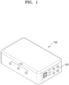
- FIG. 1 shows an example of an overall shape of a modular sensor platform apparatus according to an embodiment of the present disclosure.
- a modular sensor platform apparatus 100 may include at least one first terminal 110 that may be coupled to a power sensor and at least one second terminal 120 that may be coupled to an external sensor module and a communication module.
- the modular sensor platform apparatus 100 may include a micro-control unit that executes an algorithm predefined in a main body.
- the modular sensor platform apparatus 100 includes the first and second terminals 110 and 120 that are connectable to various sensor modules and communication modules rather than including the sensor modules and the communication modules therein, the modular sensor platform apparatus 100 may be manufactured to have a small size and a light weight. Moreover, various types of sensor modules and various types of communication modules are connectable to the modular sensor platform apparatus 100, thus being flexibly applicable to various environments. That is, each time when a physical quantity to be measured changes, the sensor module or communication module connected to the modular sensor platform apparatus 100 needs to be changed without replacing the modular sensor platform apparatus 100 or replacing or reassembling internal components thereof, thereby easily implementing the intelligence of conventional factories.
- the first terminal 110 may be connected to a non-contact current sensor that measures 3-phase power. Moreover, according to an embodiment, the first terminal 110 may be connected to various types of existing power sensors that measure power.
- the second terminal 120 may include a universal serial bus (USB) type and/or a 3-pole terminal.
- the second terminal 120 may include at least one USB A type, at least one USB C type, and at least one 3.5 mm 3-pole terminal.
- the communication module may be connected to a USB port, and a sensor that measures temperature, humidity, illuminance, vibration, etc., may be connected to a 3-pole terminal.
- the 3-pole terminal may receive an output signal from a connected resistance-based sensor and thus serve for data acquisition (DAQ) by reading the output signal without an additional micro-controller.
- DAQ data acquisition
- the modular sensor platform apparatus 100 may include at least one image sensor, i.e., a camera, or may be connected to at least one camera through the second terminal 120.
- the modular sensor platform apparatus 100 may be wirelessly connected to at least one camera through a communication module connected to the second terminal 120.
- the modular sensor platform apparatus 100 may synchronize and collect sensing values of a plurality of sensor modules through the second terminal 120. For example, the modular sensor platform apparatus 100 may collect the sensing values from the plurality of sensor modules at the same time.
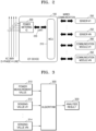
- FIG. 2 shows an example of a configuration of a modular sensor platform apparatus according to an embodiment of the present disclosure.
- the modular sensor platform apparatus 100 may include a power metering integrated circuit (IC) 200, a micro-control unit (MCU) 210, and a universal asynchronous receiver/transmitter (UART) 220.
- IC power metering integrated circuit
- MCU micro-control unit
- UART universal asynchronous receiver/transmitter
- the power metering IC 200 may identify power by using a sensing value received from a power sensor through the first terminal 110.
- the power sensor which is a current sensor of a non-contact type, may measure current flowing through each wire by being clamped to a 380 V 3-phase 4-wire power supply line.
- the power metering IC 200 may identify power, etc., based on a current sensing value of each wire, measured by the current sensor.
- the MCU 210 may be connected to at least one sensor modules 250 and 252 and at least one communication modules 260 and 262 through the second terminal 120.
- the MCU 210 may transmit sensing values received from the at least one sensor modules 250 and 252 connected in a wired communication manner through the communication modules 260 and 262 in a wireless communication manner, but in this case, the amount of traffic may increase.
- the MCU 210 may transmit a result of performing a calculation process based on the sensing values received from the at least one sensor modules 250 and 252 through the communication modules 260 and 262. An example of calculation performed by the MCU 210 will be described again with reference to FIG. 3 .
- the MCU 210 may continuously receive a sensing value from a sensor module or determine to operate a sensor module.
- the MCU 210 may receive a control command from an external source through the communication modules 260 and 262 to determine the type and number of sensor modules to operate. That is, a user may transmit a control command for operating or stopping operating sensor modules connected to the modular sensor platform apparatus 100 through a server, a user terminal, etc.
- the MCU 210 may operate first and fifth sensor modules upon receiving an operation command for the first and fifth sensor modules.
- the MCU 210 may determine whether to operate a sensor module according to a predefined condition. For example, when any one of the sensor modules is an image sensor, i.e., a camera, a lot of loads may be applied to a storage space or calculation in order for the modular sensor platform apparatus 100 to continuously process an image captured by the camera.
- the MCU 120 may normally stop operating the camera, and when a power sensing value connected to the first terminal 110 is abnormal or a value measured from various sensor modules connected to the second terminal 120 corresponds to a predefined condition (e.g., an abnormal state, etc.,) then the MCU 120 may operate a camera sensor module. That is, when an abnormal state is discovered in equipment or a space where the modular sensor platform apparatus 100 is installed, the image captured through the camera in this case may be transmitted to the server, the user terminal, etc.
- a predefined condition e.g., an abnormal state, etc.
- the communication modules 250 and 252 connected to or used for the modular sensor platform apparatus 100 may differ with a communication scheme of a place where the modular sensor platform apparatus 100 is located. For example, when ZigBee communication is required, a ZigBee communication module may be connected to the modular sensor platform apparatus 100.
- a plurality of communication modules 260 and 262 may be previously connected to the modular sensor platform apparatus 100 and when necessary, the MCU 210 may transmit and receive data through any one of the plurality of communication modules 260 and 262.
- the modular sensor platform apparatus 100 may select any one of the communication protocols according to user settings or a communication environment (e.g., a bandwidth, a communication delay, the amount of traffic, etc.,), and transmit and receive data through a communication module supporting the selected communication protocol.
- the power metering IC 200 and the MCU 210 may be connected through the UART 220. As the power metering IC 200 and the MCU 210 are physically separated from each other and transmit and receive data through the UART 220, the MCU 210 may be protected in spite of sudden occurrence of an overload, etc., in the power metering IC 200.
- FIG. 3 shows an example of a calculation method used by a micro-control unit according to an embodiment of the present disclosure.
- the MCU 210 may include an algorithm 300 that may be calculated based on a sensing value, thus serving for a sort of edge computing.
- the algorithm 300 may be stored in an internal memory of the MCU 210 or a separate memory present in the modular sensor platform apparatus 100.
- the MCU 210 may derive an analysis result 320 by inputting a power measurement value 310 identified through a power sensor and sensing values 312 and 314 measured through respective sensor modules, etc., to the algorithm 300.
- the algorithm 300 may be implemented as a general function, etc., or an artificial intelligence algorithm based on deep learning or machine learning. For example, after attached to a machine tool, etc., the modular sensor platform apparatus 100 may identify whether the machine tool is abnormal by using the power measurement value 310 and the sensing values 312 and 314, and transmit the analysis result 320, thereby reducing the amount of traffic and a calculation load of a central server when compared to transmitting the sensing values 312 and 314.
- operating conditions of various sensor modules may be predefined in the algorithm 300.
- the MCU 210 may normally operate some of the plurality of sensor modules according to the algorithm 300 to identify whether the machine tool, etc., is abnormal, and may operate the camera upon detection of abnormality through the algorithm 300 to transmit the captured image to the server, the user terminal, etc.
- the MCU 210 may receive a control command of whether to operate a specific sensor module from the user through a communication module.
- the MCU 210 may receive the control command of whether to operate the camera from an external source, operate the camera according to the control command, and transmit the captured image.
Landscapes
- Engineering & Computer Science (AREA)
- Power Engineering (AREA)
- Physics & Mathematics (AREA)
- General Physics & Mathematics (AREA)
- Computing Systems (AREA)
- Business, Economics & Management (AREA)
- Accounting & Taxation (AREA)
- Development Economics (AREA)
- Economics (AREA)
- General Business, Economics & Management (AREA)
- Arrangements For Transmission Of Measured Signals (AREA)
- Selective Calling Equipment (AREA)
Applications Claiming Priority (2)
| Application Number | Priority Date | Filing Date | Title |
|---|---|---|---|
| KR1020200166975A KR102608371B1 (ko) | 2020-12-02 | 2020-12-02 | 모듈화 센서 플랫폼 장치 |
| PCT/KR2021/014256 WO2022119111A1 (ko) | 2020-12-02 | 2021-10-14 | 모듈화 센서 플랫폼 장치 |
Publications (3)
| Publication Number | Publication Date |
|---|---|
| EP4257989A1 true EP4257989A1 (de) | 2023-10-11 |
| EP4257989A4 EP4257989A4 (de) | 2024-10-23 |
| EP4257989B1 EP4257989B1 (de) | 2026-03-04 |
Family
ID=81853996
Family Applications (1)
| Application Number | Title | Priority Date | Filing Date |
|---|---|---|---|
| EP21900799.4A Active EP4257989B1 (de) | 2020-12-02 | 2021-10-14 | Modulare sensorplattformvorrichtung |
Country Status (5)
| Country | Link |
|---|---|
| US (1) | US12399201B2 (de) |
| EP (1) | EP4257989B1 (de) |
| JP (1) | JP7639143B2 (de) |
| KR (1) | KR102608371B1 (de) |
| WO (1) | WO2022119111A1 (de) |
Families Citing this family (3)
| Publication number | Priority date | Publication date | Assignee | Title |
|---|---|---|---|---|
| KR102608371B1 (ko) | 2020-12-02 | 2023-12-01 | 서울대학교산학협력단 | 모듈화 센서 플랫폼 장치 |
| WO2024111708A1 (ko) | 2022-11-25 | 2024-05-30 | 한국해양과학기술원 | 간편 탈착을 위한 마운트가 구성된 극지용 관측 장치 |
| KR102708144B1 (ko) * | 2023-07-21 | 2024-09-19 | 최종민 | Cnc 또는 mct용 모듈형 데이터 모니터링 및 처리 시스템 |
Family Cites Families (28)
| Publication number | Priority date | Publication date | Assignee | Title |
|---|---|---|---|---|
| US6112158A (en) * | 1996-08-01 | 2000-08-29 | Siemens Power Transmission & Distribution, Llc | Service type recognition in electrical utility meter |
| US6675071B1 (en) * | 1999-01-08 | 2004-01-06 | Siemens Transmission & Distribution. Llc | Power quality utility metering system having waveform capture |
| US7085824B2 (en) * | 2001-02-23 | 2006-08-01 | Power Measurement Ltd. | Systems for in the field configuration of intelligent electronic devices |
| US7091878B2 (en) * | 2001-02-28 | 2006-08-15 | Landis+Gyr, Inc. | Electrical service disconnect having tamper detection |
| US7003412B2 (en) | 2003-09-17 | 2006-02-21 | Rockwell Automation Technologies, Inc. | Method and system for verifying voltage in an electrical system |
| US7561412B2 (en) * | 2006-09-29 | 2009-07-14 | Rockwell Automation Technologies, Inc. | System and method for automatically securing a motor control center |
| US7528612B2 (en) * | 2006-09-29 | 2009-05-05 | Rockwell Automation Technologies, Inc. | System and method for monitoring a motor control center |
| JP4987598B2 (ja) | 2007-07-17 | 2012-07-25 | 東邦瓦斯株式会社 | 宅内エネルギー管理システム |
| US20080224690A1 (en) | 2008-05-31 | 2008-09-18 | Agilent Technologies, Inc. | Embedded Directional Power Sensing |
| US10033970B2 (en) * | 2009-08-05 | 2018-07-24 | Electro Industries/Gauge Tech | Intelligent electronic device having image capture capabilities |
| KR101791030B1 (ko) | 2010-05-07 | 2017-11-20 | 삼성전자주식회사 | 전력 모니터링 장치 |
| US10036768B2 (en) | 2011-08-29 | 2018-07-31 | Landis+Gyr Llc | Method and arrangement for controlling DC power output in utility meter |
| US9213387B2 (en) * | 2011-11-14 | 2015-12-15 | Emeter Corporation | Smart meters, and systems and method for electrical power reconnection |
| WO2013136935A1 (ja) | 2012-03-13 | 2013-09-19 | インフォメティス株式会社 | センサ、センサ信号処理装置および電力線信号符号化装置 |
| JP6270323B2 (ja) * | 2012-04-13 | 2018-01-31 | キヤノン電子株式会社 | 計測モジュール、電子機器、電源タップ及び電源ユニット、並びに組込型計測モジュール |
| US9201104B2 (en) * | 2012-10-08 | 2015-12-01 | Tyco Electronics Corporation | Intelligent power sensing device |
| US20140188411A1 (en) * | 2012-12-28 | 2014-07-03 | Samsung Electro-Mechanics Co., Ltd. | Power meter |
| US20150355245A1 (en) * | 2013-01-25 | 2015-12-10 | Circuitmeter Inc. | System and method for monitoring an electrical network |
| US9575101B2 (en) * | 2013-03-18 | 2017-02-21 | GRID20/20, Inc. | Power monitoring systems and methods |
| US9632120B2 (en) * | 2014-12-24 | 2017-04-25 | Infineon Technologies Austria Ag | System and method for measuring power in a power factor converter |
| US9897647B2 (en) * | 2015-05-27 | 2018-02-20 | Eaton Corporation | Method and apparatus to commission voltage sensors and branch circuit current sensors for branch circuit monitoring systems |
| KR101774233B1 (ko) | 2015-07-24 | 2017-09-05 | (주)와플 | 센서 신호 검출 시스템 및 이를 구비하는 스마트 플러그 |
| KR20180058113A (ko) | 2016-11-23 | 2018-05-31 | 부산대학교 산학협력단 | 가전기기 고유값 추출을 이용한 가전기기 분류 시스템 및 방법 |
| JP6653691B2 (ja) | 2017-09-26 | 2020-02-26 | Kddi株式会社 | 学習装置、学習システム、判定装置及び判定方法 |
| KR102071635B1 (ko) * | 2018-07-02 | 2020-01-30 | 서울대학교산학협력단 | 모듈화 스마트 센서-플러그 플랫폼 장치 및 이를 이용한 모듈화 스마트 센서-플러그 시스템 |
| KR20190090368A (ko) * | 2019-07-11 | 2019-08-01 | 엘지전자 주식회사 | 지능적 가전 제어 방법, 가전을 제어하는 장치 및 지능형 컴퓨팅 디바이스 |
| US11283669B1 (en) * | 2020-09-04 | 2022-03-22 | Johnson Controls Tyco IP Holdings LLP | Building management system with control framework |
| KR102608371B1 (ko) | 2020-12-02 | 2023-12-01 | 서울대학교산학협력단 | 모듈화 센서 플랫폼 장치 |
-
2020
- 2020-12-02 KR KR1020200166975A patent/KR102608371B1/ko active Active
-
2021
- 2021-10-14 JP JP2023534008A patent/JP7639143B2/ja active Active
- 2021-10-14 US US18/255,826 patent/US12399201B2/en active Active
- 2021-10-14 WO PCT/KR2021/014256 patent/WO2022119111A1/ko not_active Ceased
- 2021-10-14 EP EP21900799.4A patent/EP4257989B1/de active Active
Also Published As
| Publication number | Publication date |
|---|---|
| US12399201B2 (en) | 2025-08-26 |
| US20240103055A1 (en) | 2024-03-28 |
| KR20220077743A (ko) | 2022-06-09 |
| WO2022119111A1 (ko) | 2022-06-09 |
| EP4257989A4 (de) | 2024-10-23 |
| JP2023553881A (ja) | 2023-12-26 |
| EP4257989B1 (de) | 2026-03-04 |
| KR102608371B1 (ko) | 2023-12-01 |
| JP7639143B2 (ja) | 2025-03-04 |
Similar Documents
| Publication | Publication Date | Title |
|---|---|---|
| US12399201B2 (en) | Modular sensor platform apparatus | |
| KR101086005B1 (ko) | 태양광 모듈 모니터링 시스템 | |
| US9989567B2 (en) | Method of measuring the energy consumption of the branches of an electrical network and measurement equipment implementing said method | |
| CA2789317A1 (en) | A system for monitoring eletrical power distribution lines in a power grid using a wireless sensor network | |
| KR101790659B1 (ko) | 패널 미터의 전기 데이터를 타임스탬핑하기 위한 장치 및 방법들 | |
| KR101529476B1 (ko) | 태양광 모듈 스트링의 절연저항 감시 시스템 | |
| Vincent et al. | Development of an in-vehicle power line communication network with in-situ instrumented smart cells | |
| KR20210147890A (ko) | 전기 시스템 모니터링 및/또는 고장 검출 시스템 및 방법 | |
| KR20190093339A (ko) | 지능형 원격검침 시스템 | |
| EP0528634A2 (de) | Leistungsüberwachungssystem für eine Mehrzahl lokaler Unterstationen mit einer Rundum-Augenblickswertabfrage von einer Zentralstation aus | |
| EP3553536B1 (de) | Kombination eines sensormoduls und einer sicherung, und verwendung eines sensormoduls in der kombination | |
| JP4122646B2 (ja) | 検針値送信方法、検針値送信システム及び検針値送信端局 | |
| Navamanikumar et al. | IOT Based Real Time Transformer Health Monitoring System and Phase Preventor | |
| CN112470487B (zh) | 用于现场设备的远程监测和诊断的方法和装置 | |
| JP7852304B2 (ja) | データ出力装置、蓄電素子監視システム及びデータ出力方法 | |
| EP4332940A1 (de) | Messvorrichtung und verfahren zur übertragung der ausgabe eines sensors in der messvorrichtung | |
| EP3499928A1 (de) | Bestimmung der signalqualität in einem weitbereichsnetzwerk mit niedriger leistung | |
| Campbell et al. | From Energy Audits to Monitoring Megawatt Loads: A Flexible and Deployable Power Metering System | |
| CN114268642A (zh) | 一种多协议无线数据汇集装置 | |
| US20240069108A1 (en) | Method for evaluating the quantity of electrical energy consumed by a communicating object | |
| WO2025115506A1 (ja) | バッテリーマネジメントシステム、管理装置、周期設定方法およびプログラム | |
| CN110620714A (zh) | 应用于小空间及复杂环境下的自动建模智能连接件系统 | |
| EP2157733A1 (de) | Verfahren und Vorrichtung zur Datenübertragung zwischen einem drahtlosen Sensornetzwerk und einem Datensammelsystem | |
| CN217560772U (zh) | 一种检重分选秤智能终端 | |
| KR20020076918A (ko) | 축전지 감시 시스템 |
Legal Events
| Date | Code | Title | Description |
|---|---|---|---|
| STAA | Information on the status of an ep patent application or granted ep patent |
Free format text: STATUS: THE INTERNATIONAL PUBLICATION HAS BEEN MADE |
|
| PUAI | Public reference made under article 153(3) epc to a published international application that has entered the european phase |
Free format text: ORIGINAL CODE: 0009012 |
|
| STAA | Information on the status of an ep patent application or granted ep patent |
Free format text: STATUS: REQUEST FOR EXAMINATION WAS MADE |
|
| 17P | Request for examination filed |
Effective date: 20230630 |
|
| AK | Designated contracting states |
Kind code of ref document: A1 Designated state(s): AL AT BE BG CH CY CZ DE DK EE ES FI FR GB GR HR HU IE IS IT LI LT LU LV MC MK MT NL NO PL PT RO RS SE SI SK SM TR |
|
| DAV | Request for validation of the european patent (deleted) | ||
| DAX | Request for extension of the european patent (deleted) | ||
| A4 | Supplementary search report drawn up and despatched |
Effective date: 20240925 |
|
| RIC1 | Information provided on ipc code assigned before grant |
Ipc: G01R 21/133 20060101ALI20240919BHEP Ipc: G01R 22/10 20060101ALI20240919BHEP Ipc: G01R 19/25 20060101ALI20240919BHEP Ipc: G01R 22/06 20060101AFI20240919BHEP |
|
| GRAP | Despatch of communication of intention to grant a patent |
Free format text: ORIGINAL CODE: EPIDOSNIGR1 |
|
| STAA | Information on the status of an ep patent application or granted ep patent |
Free format text: STATUS: GRANT OF PATENT IS INTENDED |
|
| INTG | Intention to grant announced |
Effective date: 20251121 |
|
| GRAS | Grant fee paid |
Free format text: ORIGINAL CODE: EPIDOSNIGR3 |
|
| GRAA | (expected) grant |
Free format text: ORIGINAL CODE: 0009210 |
|
| STAA | Information on the status of an ep patent application or granted ep patent |
Free format text: STATUS: THE PATENT HAS BEEN GRANTED |
|
| AK | Designated contracting states |
Kind code of ref document: B1 Designated state(s): AL AT BE BG CH CY CZ DE DK EE ES FI FR GB GR HR HU IE IS IT LI LT LU LV MC MK MT NL NO PL PT RO RS SE SI SK SM TR |
|
| REG | Reference to a national code |
Ref country code: CH Ref legal event code: F10 Free format text: ST27 STATUS EVENT CODE: U-0-0-F10-F00 (AS PROVIDED BY THE NATIONAL OFFICE) Effective date: 20260304 Ref country code: GB Ref legal event code: FG4D |
|
| REG | Reference to a national code |
Ref country code: IE Ref legal event code: FG4D |
|
| REG | Reference to a national code |
Ref country code: DE Ref legal event code: R096 Ref document number: 602021049488 Country of ref document: DE |