EP4257945B1 - Anhänger in form eines transportmotorlosen kühlaggregats mit einem zapfen mit integriertem sensor und entsprechendes verfahren - Google Patents
Anhänger in form eines transportmotorlosen kühlaggregats mit einem zapfen mit integriertem sensor und entsprechendes verfahren Download PDFInfo
- Publication number
- EP4257945B1 EP4257945B1 EP22167319.7A EP22167319A EP4257945B1 EP 4257945 B1 EP4257945 B1 EP 4257945B1 EP 22167319 A EP22167319 A EP 22167319A EP 4257945 B1 EP4257945 B1 EP 4257945B1
- Authority
- EP
- European Patent Office
- Prior art keywords
- trailer
- tractor
- kingpin
- sensor
- generator generates
- Prior art date
- Legal status (The legal status is an assumption and is not a legal conclusion. Google has not performed a legal analysis and makes no representation as to the accuracy of the status listed.)
- Active
Links
Images


Classifications
-
- H—ELECTRICITY
- H02—GENERATION; CONVERSION OR DISTRIBUTION OF ELECTRIC POWER
- H02J—ELECTRIC POWER NETWORKS; CIRCUIT ARRANGEMENTS OR SYSTEMS FOR SUPPLYING OR DISTRIBUTING ELECTRIC POWER; SYSTEMS FOR STORING ELECTRIC ENERGY
- H02J7/00—Circuit arrangements for charging or discharging batteries or for supplying loads from batteries
- H02J7/14—Circuit arrangements for charging or discharging batteries or for supplying loads from batteries for charging batteries from dynamo-electric generators driven at varying speed, e.g. on vehicle
-
- G—PHYSICS
- G01—MEASURING; TESTING
- G01L—MEASURING FORCE, STRESS, TORQUE, WORK, MECHANICAL POWER, MECHANICAL EFFICIENCY, OR FLUID PRESSURE
- G01L5/00—Apparatus for, or methods of, measuring force, work, mechanical power, or torque, specially adapted for specific purposes
- G01L5/13—Apparatus for, or methods of, measuring force, work, mechanical power, or torque, specially adapted for specific purposes for measuring the tractive or propulsive power of vehicles
- G01L5/136—Force sensors associated with a vehicle traction coupling
-
- B—PERFORMING OPERATIONS; TRANSPORTING
- B60—VEHICLES IN GENERAL
- B60D—VEHICLE CONNECTIONS
- B60D1/00—Traction couplings; Hitches; Draw-gear; Towing devices
- B60D1/24—Traction couplings; Hitches; Draw-gear; Towing devices characterised by arrangements for particular functions
-
- B—PERFORMING OPERATIONS; TRANSPORTING
- B60—VEHICLES IN GENERAL
- B60D—VEHICLE CONNECTIONS
- B60D1/00—Traction couplings; Hitches; Draw-gear; Towing devices
- B60D1/24—Traction couplings; Hitches; Draw-gear; Towing devices characterised by arrangements for particular functions
- B60D1/248—Traction couplings; Hitches; Draw-gear; Towing devices characterised by arrangements for particular functions for measuring, indicating or displaying the weight
-
- B—PERFORMING OPERATIONS; TRANSPORTING
- B60—VEHICLES IN GENERAL
- B60D—VEHICLE CONNECTIONS
- B60D1/00—Traction couplings; Hitches; Draw-gear; Towing devices
- B60D1/58—Auxiliary devices
- B60D1/62—Auxiliary devices involving supply lines, electric circuits or the like
-
- B—PERFORMING OPERATIONS; TRANSPORTING
- B60—VEHICLES IN GENERAL
- B60H—ARRANGEMENTS OF HEATING, COOLING, VENTILATING OR OTHER AIR-TREATING DEVICES SPECIALLY ADAPTED FOR PASSENGER OR GOODS SPACES OF VEHICLES
- B60H1/00—Heating, cooling or ventilating devices
- B60H1/00421—Driving arrangements for parts of a vehicle air-conditioning
- B60H1/00428—Driving arrangements for parts of a vehicle air-conditioning electric
-
- B—PERFORMING OPERATIONS; TRANSPORTING
- B60—VEHICLES IN GENERAL
- B60R—VEHICLES, VEHICLE FITTINGS, OR VEHICLE PARTS, NOT OTHERWISE PROVIDED FOR
- B60R16/00—Electric or fluid circuits specially adapted for vehicles and not otherwise provided for; Arrangement of elements of electric or fluid circuits specially adapted for vehicles and not otherwise provided for
- B60R16/02—Electric or fluid circuits specially adapted for vehicles and not otherwise provided for; Arrangement of elements of electric or fluid circuits specially adapted for vehicles and not otherwise provided for electric constitutive elements
- B60R16/03—Electric or fluid circuits specially adapted for vehicles and not otherwise provided for; Arrangement of elements of electric or fluid circuits specially adapted for vehicles and not otherwise provided for electric constitutive elements for supply of electrical power to vehicle subsystems or for
- B60R16/033—Electric or fluid circuits specially adapted for vehicles and not otherwise provided for; Arrangement of elements of electric or fluid circuits specially adapted for vehicles and not otherwise provided for electric constitutive elements for supply of electrical power to vehicle subsystems or for characterised by the use of electrical cells or batteries
-
- B—PERFORMING OPERATIONS; TRANSPORTING
- B62—LAND VEHICLES FOR TRAVELLING OTHERWISE THAN ON RAILS
- B62D—MOTOR VEHICLES; TRAILERS
- B62D33/00—Superstructures for load-carrying vehicles
- B62D33/04—Enclosed load compartments ; Frameworks for movable panels, tarpaulins or side curtains
- B62D33/048—Enclosed load compartments ; Frameworks for movable panels, tarpaulins or side curtains for refrigerated goods vehicles
-
- B—PERFORMING OPERATIONS; TRANSPORTING
- B62—LAND VEHICLES FOR TRAVELLING OTHERWISE THAN ON RAILS
- B62D—MOTOR VEHICLES; TRAILERS
- B62D53/00—Tractor-trailer combinations; Road trains
- B62D53/04—Tractor-trailer combinations; Road trains comprising a vehicle carrying an essential part of the other vehicle's load by having supporting means for the front or rear part of the other vehicle
- B62D53/08—Fifth wheel traction couplings
- B62D53/0842—King pins
-
- G—PHYSICS
- G01—MEASURING; TESTING
- G01D—MEASURING NOT SPECIALLY ADAPTED FOR A SPECIFIC VARIABLE; ARRANGEMENTS FOR MEASURING TWO OR MORE VARIABLES NOT COVERED IN A SINGLE OTHER SUBCLASS; TARIFF METERING APPARATUS; MEASURING OR TESTING NOT OTHERWISE PROVIDED FOR
- G01D21/00—Measuring or testing not otherwise provided for
- G01D21/02—Measuring two or more variables by means not covered by a single other subclass
-
- G—PHYSICS
- G07—CHECKING-DEVICES
- G07C—TIME OR ATTENDANCE REGISTERS; REGISTERING OR INDICATING THE WORKING OF MACHINES; GENERATING RANDOM NUMBERS; VOTING OR LOTTERY APPARATUS; ARRANGEMENTS, SYSTEMS OR APPARATUS FOR CHECKING NOT PROVIDED FOR ELSEWHERE
- G07C5/00—Registering or indicating the working of vehicles
- G07C5/008—Registering or indicating the working of vehicles communicating information to a remotely located station
-
- H—ELECTRICITY
- H02—GENERATION; CONVERSION OR DISTRIBUTION OF ELECTRIC POWER
- H02J—ELECTRIC POWER NETWORKS; CIRCUIT ARRANGEMENTS OR SYSTEMS FOR SUPPLYING OR DISTRIBUTING ELECTRIC POWER; SYSTEMS FOR STORING ELECTRIC ENERGY
- H02J7/00—Circuit arrangements for charging or discharging batteries or for supplying loads from batteries
- H02J7/14—Circuit arrangements for charging or discharging batteries or for supplying loads from batteries for charging batteries from dynamo-electric generators driven at varying speed, e.g. on vehicle
- H02J7/1469—Regulation of the charging current or voltage otherwise than by variation of field
- H02J7/1476—Regulation of the charging current or voltage otherwise than by variation of field by mechanical action on the generator
-
- H—ELECTRICITY
- H02—GENERATION; CONVERSION OR DISTRIBUTION OF ELECTRIC POWER
- H02J—ELECTRIC POWER NETWORKS; CIRCUIT ARRANGEMENTS OR SYSTEMS FOR SUPPLYING OR DISTRIBUTING ELECTRIC POWER; SYSTEMS FOR STORING ELECTRIC ENERGY
- H02J7/00—Circuit arrangements for charging or discharging batteries or for supplying loads from batteries
- H02J7/90—Regulation of charging or discharging current or voltage
- H02J7/933—Regulation of charging or discharging current or voltage the cycle being controlled or terminated in response to electric parameters
-
- H—ELECTRICITY
- H02—GENERATION; CONVERSION OR DISTRIBUTION OF ELECTRIC POWER
- H02K—DYNAMO-ELECTRIC MACHINES
- H02K7/00—Arrangements for handling mechanical energy structurally associated with dynamo-electric machines, e.g. structural association with mechanical driving motors or auxiliary dynamo-electric machines
- H02K7/18—Structural association of electric generators with mechanical driving motors, e.g. with turbines
- H02K7/1807—Rotary generators
- H02K7/1861—Rotary generators driven by animals or vehicles
-
- B—PERFORMING OPERATIONS; TRANSPORTING
- B60—VEHICLES IN GENERAL
- B60P—VEHICLES ADAPTED FOR LOAD TRANSPORTATION OR TO TRANSPORT, TO CARRY, OR TO COMPRISE SPECIAL LOADS OR OBJECTS
- B60P3/00—Vehicles adapted to transport, to carry or to comprise special loads or objects
- B60P3/20—Refrigerated goods vehicles
Definitions
- the present invention relates to a trailer in the form of a transport engineless refrigeration and a related mothod.
- cold chain distribution systems are used to transport and distribute cargo, or more specifically perishable goods and environmentally sensitive goods (herein referred to as perishable goods) that may be susceptible to temperature, humidity, and other environmental factors.
- Perishable goods may include but are not limited to fruits, vegetables, grains, beans, nuts, eggs, dairy, seed, flowers, meat, poultry, fish, ice, and pharmaceuticals.
- cold chain distribution systems allow perishable goods to be effectively transported and distributed without damage or other undesirable effects.
- Refrigerated trailers are commonly used to transport perishable goods in a cold chain distribution system.
- refrigerated trailers include a refrigeration unit for the supply of cold air to a cargo space and together these are referred to as transportation refrigeration units, or TRUs.
- the refrigeration unit of such TRUs may comprise a compressor, a condenser with one or more associated condenser fans, an expansion device, and an evaporator with one or more associated evaporator fans, which are connected via appropriate refrigerant lines in a closed refrigerant flow circuit.
- the refrigeration unit may be mounted to the TRU trailer in operative association with a cargo space defined within the trailer for maintaining a controlled temperature environment within the cargo space.
- Air or an air/gas mixture is drawn from the interior volume of the cargo space by means of the evaporator fan(s) associated with the evaporator, passed through the airside of the evaporator in heat exchange relationship with refrigerant whereby the refrigerant absorbs heat from the air, thereby cooling the air. The cooled air is then supplied back to the cargo space.
- the compressor On commercially available TRUs, the compressor, and typically other components of the transportation refrigeration unit, may be powered during transit by an on-board battery that is charged by a generator. In such systems, a prime mover of the system drives a generator that generates power.
- a known type of electrically driven TRU involves rigidly coupling a wheel axle of the TRU to a generator (of the rotational type) to generate electrical power.
- the generated power is stored in a battery and can be used to power an electric motor for driving the refrigerant compressor of the transportation refrigeration unit and also can be used for powering electric fan motors, for driving the condenser and evaporator motors, and for powering electric heaters associated with the evaporator.
- the battery can supply power to the other components of the TRU.
- EP 2 899 101 A1 discloses a kingpin for mounting to a semitrailer.
- the kingpin comprises a pin body detachably engageable with a towing vehicle-side semitrailer coupling and a sensor device disposed at the pin body and configured to detect a driving state of the semitrailer.
- US 2019/265112 A1 discloses a magneto-elastically-based active force sensor, used with a tow coupling between a towed and a towing vehicle, which outputs a signal useful for determining forces acting on the coupling.
- the outputted force information may be provided by processor-enabled embedded software algorithms that take inputs from the force sensor and other sensors, may be used by one or more vehicle systems during operating of the vehicle, such as engine, braking, stability, safety, and informational systems.
- the force sensor includes directionally-sensitive magnetic field sensing elements inside the sensor, and shielding may be used around the sensors to reduce the influence of external magnetic fields on the sensing elements.
- the force sensor may be used with different tow coupling devices installed on different types of automobile cars and trucks.
- DE 10 2006 057327 A1 discloses a device for determining trailer force on the trailer of a truck trailer.
- the device comprises a base element, which is fastened on a frame of a trailer traction machine.
- a saddle plate is provided, which is fixed on the base element.
- the base element has a receiver opening, which is formed for receiving a kingpin of a semitrailer.
- Two 3-component force measuring elements are provided, which are arranged between the saddle plate and the base element.
- US 2007/103280 A1 discloses a towing load detection system for detecting whether a vehicle is towing an object.
- the system includes a controller and at least one proximity sensor operable to detect the presence of the object being towed.
- the controller is operable to cause a vehicle effect when the proximity sensor detects that the vehicle is towing an object.
- a kingpin for connecting a trailer to a tractor, the kingpin comprising: an integrated sensor arranged to measure a force applied to the kingpin, and a data connection arranged to transmit data of a force measured by the integrated sensor.
- a kingpin also referred to as a fifth-wheel coupling, is part of a trailer/TRU that provides the link between a tractor (via the fifth wheel of the tractor) and the trailer/TRU.
- the sensor may measure a vector force (both direction and magnitude). This data may be obtained in real time and is valuable in deciding when to use the generator to generate power, thereby improving fuel efficiency.
- the kingpin may comprise a plurality of integrated sensors. Each sensor may be arranged to measure to measure a force applied to the kingpin. Each sensor may be arranged to transmit data of a measured force via the data connection or each may have its own data connection for this purpose. This may provide a greater amount of data and/or more accurate data. Teachings below relating to specific of the sensor may apply to any/each of the plurality of sensors.
- the sensor may be a torque sensor. This may allow a reaction force on the trailer (produced by the tractor) to be measured.
- the sensor may extend partway through the kingpin in the vertical direction.
- the sensor may be configured to measure forces acting on the kingpin in the horizontal direction. In this way, the sensors may be arranged to measured forces in the same plane as push/pull forces on the trailer and a connected tractor.
- the invention provides a trailer in the form of a transport engineless refrigeration unit as defined in claim 1.
- the kingpin may include any of the optional features described herein.
- control unit is configured to control when the generator generates power and/or to what magnitude the generator generates power based at least in part on data of a force measured by the integrated sensor of the kingpin.
- this may optimise the efficiency of the TRU, by better control of the time/magnitude of generating power.
- the trailer may comprise an accelerometer configured to measure acceleration of the trailer and/or a clinometer configured to measure an incline of the trailer.
- the control unit may be configured to control when the generator generates power and/or to what magnitude the generator generates power based at least in part on a measured acceleration of the trailer and/or a measured incline of the trailer.
- control of the generator can be further optimised. For example, if the trailer moves onto a downhill gradient but there is no push or pull force (i.e. it is moving at a steady speed), then it would be beneficial to generate power using the generator as it is likely to accelerate due to gravitational forces.
- the trailer may comprise a speedometer configured the measure a speed of the trailer; and/or a brake sensor configured to detect a status of a brake of the trailer.
- the control unit may be configured to control when the generator generates power and/or to what magnitude the generator generates power based at least in part on a measured speed of the trailer and/or a status of the brake of the trailer.
- a driver's intention may be determined (e.g. they have pressed the brake sharply to decelerate quickly). This information may be useful in determining when/to what magnitude power may be generated, e.g. a desire for sharp declaration from a high speed may be optimal for power generation, as kinetic energy is used to power the generator rather than being wasted.
- the trailer may comprise a weight sensor to measure the mass of trailer.
- the control unit may be configured to control when the generator generates power and/or to what magnitude the generator generates power based at least in part on the mass of the trailer.
- the trailer may comprise a sensor configured to measure a state of charge of a battery.
- the control unit may be configured to control when the generator generates power and/or to what magnitude the generator generates power based at least in part on a measured state of charge of the battery.
- the control unit may control the generator to generate power if the state of charge is below a predetermined threshold regardless of other measurements/data.
- the generator may generate power regardless of the other information acquired in order to ensure that the batter does not run out of charge. This is particularly important when a battery is used to cool a cargo space, as otherwise the cargo could be spoiled.
- the control unit may be configured to control when the generator generates power and/or to what magnitude the generator generates power based at least in part on power requirements of the transport engineless refrigeration unit. For example, if no power is required to chill a cargo space (e.g. the trailer is empty) then the generator may not charge the battery and/or the battery may not power the refrigeration unit.
- the present invention provides a vehicle comprising a tractor and a trailer according to the the invention wherein the vehicle comprises: a data connection between the tractor and the trailer, and the tractor comprises: a speedometer configured the measure a speed of the tractor; and/or a brake sensor configured to detect a status of the brake of the tractor, wherein the speedometer and/or the brake sensor are connected to the control unit of the trailer via the data connection and the control unit is configured to control when the generator generates power and/or to what magnitude the generator generates power based at least in part on a measured speed of the tractor and/or a status of the brake of the tractor.
- the trailer may include any of the optional features described herein.
- the speedometer and/or brake sensor of the tractor can supply data to be used in optimising the control of the generator.
- the tractor may comprise a fuel consumption sensor configured to measure fuel consumption of the tractor and/or a pedal position sensor configured to measure a position of an accelerator pedal, brake pedal or clutch.
- the control unit may be configured to control when the generator generates power and/or to what magnitude the generator generates power based at least in part on fuel consumption of the tractor and/or a pedal position.
- the vehicle may comprise a telematics unit arranged to send measurements/data between the tractor and trailer and/or to a remote server.
- the telematics unit may be positioned in the TRU.
- the data described herein may be stored for future use and optimisation processes.
- control methods described herein may be altered based at least in part on measurements/data stored on a remote server.
- the integrated sensor may be a torque sensor and the kingpin may include any of the optional features discussed in relation to the first aspect.
- the present invention provides a method of optimising control of a trailer connected to a tractor as defined in claim 10.
- the method is performed by the controller described above.
- the determining of an optimal time for the generator to generate power and/or an optimal magnitude of power to generate may additionally be based on any one or a combination of: a measured acceleration of the trailer; a measured incline of the trailer; a measured speed of the trailer; a status of a brake of the trailer; a mass of the trailer; a measured state of charge of the battery; and power requirements of the transport engineless refrigeration unit.
- the determining of an optimal time for the generator to generate power and/or an optimal magnitude of power to generate may additionally be based on any one or a combination of: a measured speed of the tractor; a status of the brake of the tractor; fuel consumption of the tractor; fuel level of the tractor; a position of an accelerator pedal, brake pedal or clutch of the tractor.
- the vehicle system 100 comprises a tractor 110 and a trailer 120 in the form of a transport refrigeration unit (TRU).
- the TRU 120 comprises a refrigeration unit 122 for the refrigeration of a cargo space (not shown).
- the TRU 120 also comprises a battery pack 124, a generator 126 rigidly coupled to a wheel axle of the transport refrigeration system and arranged to charge the battery, an EBS (braking and suspension measurement) system 128, and ABS (speed measurement) system 130.
- the battery pack 124 comprises a controller configured to control the generator 126, battery pack 124 and refrigeration unit 122 and receive measurements form the various measurement systems.
- the vehicle system 100 also comprises a data connection 132 between the tractor 110 and trailer 120 in the form of a CAN bus.
- a data connection 132 between the tractor 110 and trailer 120 in the form of a CAN bus.
- data regarding braking and suspension of the trailer 120 is sent via this connection.
- the connection 128 is not equipped to handle any other data transfer between the tractor and trailer.
- the generator 126 In use the generator 126 generates power, and the controller prioritises supply of this power the TRU 120. If the TRU 120 is off, or is not consuming all the generated power, the controller diverts the remaining power to charge the battery 124.
- a vehicle system 200 including a tractor 210 and a trailer in the form of a transport refrigeration unit (TRU) 220 having a kingpin 234 with an integrated sensor 238 arranged to measure a force applied to the kingpin 234.
- TRU transport refrigeration unit
- the TRU 220 comprises a refrigeration unit 222 for the refrigeration of a cargo space (not shown).
- the TRU 220 also comprises a battery pack 224 for powering the refrigeration unit 222, a generator 226 rigidly coupled to a wheel axle of the transport refrigeration system and for charging the battery pack 224, an EBS (braking and suspension measurement) system 228, an accelerometer and clinometer system 236, and an ABS (speed measurement) system 230.
- the battery pack 224 comprises a sensor for measuring its state of charge (SOC) and a controller configured to control the generator 226, battery pack 224 and refrigeration unit 222.
- SOC state of charge
- the vehicle system 200 also comprises a data connection 232 between the tractor 210 and trailer 220 in the form of a CAN bus. In use, data regarding braking and suspension of the trailer 220 is sent via this connection.
- measurements of a force applied to the kingpin 234 are sent via a data connection 239 to the controller.
- the controller controls when the generator 226 generates power to charge the battery pack 224. For example, if the trailer 220 is being pushed, or decelerated, by the tractor 210 then it is clear that the system as a whole is slowing down and so it would be beneficial to use the kinetic energy of the trailer 220 to generate power via the generator 226. In contrast, if the trailer 220 is being pulled, or accelerated, by the tractor 210 then it is clear that the system as whole is accelerating and so it would be beneficial to not use the kinetic energy of the trailer 220 to generate power as doing so would reduce the extent of acceleration.
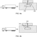
- the kingpin 234 is shown in more detail.
- the kingpin 234 comprises an integrated torque sensor 238.
- the torque sensor 238 extends partway through the kingpin 234 in the vertical direction and is configured to measure forces acting in the horizontal plane (labelled X).
- the kingpin 234 is part of the trailer 220, and connects to the fifth wheel 240 of the tractor 210 in a conventional way to connect the two. It will be appreciated that additional sensors could be incorporated into the kingpin 234.
- Figure 4a shows the state of the kingpin 234 when the tractor is pulling the trailer, and accelerating it.
- the force 242 will be measured by the integrated sensor 238 and transmitted to the controller previously discussed.
- Figure 4b shows the state of the kingpin 234 when the tractor is pushing, or decelerating the trailer, it is clear that the horizontal force 242 being measured would then be in the opposite direction.
- the controller receives data from sensors including the integrated sensor 238 of the kingpin 234 indicating a force, a speedometer indicating vehicle speed, accelerometer indicating vehicle acceleration, clinometer indicating incline and brake sensor indicating a state of the brake on the trailer. These various indications are shown in columns 1 to 5.
- the controller receives data regarding a state of charge of the battery pack 224. From the data provided by these sensors it is possible to deduce (amongst other things) three pieces of information: the fuel consumption of the tractor 210; the change in momentum of the trailer 220 and the incline of the road. These are shown in columns 6 to 8.
- the controller is configured to make decision on whether to use the generator 226 to generate power and to what extent power should be generated. For example, in row 6, it can be seen that it has been deduced that the vehicle 220 is braking on a downhill slope, so it would be beneficial to generate maximum power with the generator 226 in order to recover some of the kinetic energy of the trailer 220 to charge the battery 224 rather than it simply being wasted. In contrast, in row 5 it can be seen that the vehicle 200 is accelerating on an uphill incline and so the fuel consumption of the tractor 210 is very high. In this instance, the controller does not generate power with the generator (unless the state of charge of the battery is dangerously low) as doing so wold increase fuel consumption even more, and reduce acceleration.
Landscapes
- Engineering & Computer Science (AREA)
- Mechanical Engineering (AREA)
- Transportation (AREA)
- Chemical & Material Sciences (AREA)
- Combustion & Propulsion (AREA)
- Physics & Mathematics (AREA)
- Power Engineering (AREA)
- General Physics & Mathematics (AREA)
- Thermal Sciences (AREA)
- Analytical Chemistry (AREA)
- Electric Propulsion And Braking For Vehicles (AREA)
- Vehicle Body Suspensions (AREA)
- Force Measurement Appropriate To Specific Purposes (AREA)
- Measurement Of Length, Angles, Or The Like Using Electric Or Magnetic Means (AREA)
Claims (12)
- Anhänger (220) in Form eines Transportkühlaggregats ohne Motor, wobei der Anhänger umfasst:einen Achsschenkelbolzen (234), der einen integrierten Sensor (238), der angeordnet ist, um eine auf den Achsschenkelbolzen ausgeübte Kraft zu messen, und eine Datenverbindung (239) umfasst, die angeordnet ist, um Daten einer durch den integrierten Sensor gemessenen Kraft zu übertragen,eine Steuereinheit, die angeordnet ist, um die Daten einer Kraft zu empfangen, die durch den integrierten Sensor gemessen wird, ein Kühlaggregat (222),eine Batterie (224), die angeordnet ist, um das Kühlaggregat, die Steuereinheit und/oder den integrierten Sensor des Achsschenkelbolzens mit Energie zu versorgen; undeinen Generator (226), der angeordnet ist, um Energie von einer Achse des Anhängers zu erzeugen, um die Batterie zu laden,wobei die Steuereinheit eingerichtet ist, um zu steuern, wann der Generator Energie erzeugt und/oder in welcher Größenordnung der Generator Energie erzeugt, zumindest teilweise basierend auf Daten einer Kraft (242), die durch den integrierten Sensor des Achsschenkelbolzens gemessen wird.
- Anhänger (220) nach Anspruch 1, wobei sich der integrierte Sensor des Achsschenkelbolzens teilweise durch den Achsschenkelbolzen in einer vertikalen Richtung erstreckt und der Sensor ein Drehmomentsensor ist, der eingerichtet ist, um Kräfte (242) zu messen, die auf den Achsschenkelbolzen in einer horizontalen Richtung wirken.
- Anhänger (220) nach Anspruch 1 oder Anspruch 2, umfassend:einen Beschleunigungsmesser (236), der eingerichtet ist, um eine Beschleunigung des Anhängers zu messen, und/oder ein Neigungsmesser (236), der eingerichtet ist, um eine Neigung des Anhängers zu messen,wobei die Steuereinheit eingerichtet ist, um zu steuern, wann der Generator Energie erzeugt und/oder in welcher Größenordnung der Generator Energie erzeugt, zumindest teilweise basierend auf einer gemessenen Beschleunigung des Anhängers und/oder einer gemessenen Neigung des Anhängers.
- Anhänger (220) nach einem der Ansprüche 1 bis 3, umfassend:einen Geschwindigkeitsmesser (230), der eingerichtet ist, um eine Geschwindigkeit des Anhängers zu messen; und/oder einen Bremssensor (228), der eingerichtet ist, einen Zustand einer Bremse des Anhängers zu erfassen,wobei die Steuereinheit eingerichtet ist, um zu steuern, wann der Generator Energie erzeugt und/oder in welcher Größenordnung der Generator Energie erzeugt, zumindest teilweise basierend auf einer gemessenen Geschwindigkeit des Anhängers und/oder einem Zustand der Bremse des Anhängers.
- Anhänger (220) nach einem der Ansprüche 1 bis 4, umfassend: einen Gewichtssensor, um die Masse des Anhängers zu messen, wobei die Steuereinheit eingerichtet ist, um zu steuern, wann der Generator Energie erzeugt und/oder in welcher Größenordnung der Generator Energie erzeugt, zumindest teilweise basierend auf der Masse des Anhängers.
- Anhänger (220) nach einem der Ansprüche 1 bis 5, umfassend: einen Sensor, der eingerichtet ist, um einen Ladezustand der Batterie zu messen, wobei die Steuereinheit eingerichtet ist, um zu steuern, wann der Generator Energie erzeugt und/oder in welcher Größenordnung der Generator Energie erzeugt, zumindest teilweise basierend auf einem gemessenen Ladezustand der Batterie.
- Fahrzeug (200), umfassend eine Zugmaschine (210) und einen Anhänger (220), nach einem der Ansprüche 1 bis 6, wobei das Fahrzeug umfasst:
eine Datenverbindung (232) zwischen der Zugmaschine und dem Anhänger, und wobei die Zugmaschine umfasst:einen Geschwindigkeitsmesser, der eingerichtet ist, um eine Geschwindigkeit der Zugmaschine zu messen; und/oder einen Bremssensor, der eingerichtet ist, um einen Zustand der Bremse der Zugmaschine zu erfassen,wobei der Geschwindigkeitsmesser und/oder der Bremssensor mit der Steuereinheit des Anhängers über die Datenverbindung verbunden sind und die Steuereinheit eingerichtet ist, um zu steuern, wann der Generator Energie erzeugt und/oder in welcher Größenordnung der Generator Energie erzeugt, zumindest teilweise basierend auf einer gemessenen Geschwindigkeit der Zugmaschine und/oder einem Zustand der Bremse der Zugmaschine. - Fahrzeug (200) nach Anspruch 7, wobei die Zugmaschine umfasst:
einen Kraftstoffverbrauchssensor, der eingerichtet ist, um einen Kraftstoffverbrauch der Zugmaschine zu messen, und/oder einen Pedalstellungssensor, der eingerichtet ist, um eine Stellung eines Gaspedals, eines Bremspedals oder einer Kupplung zu messen, und wobei die Steuereinheit eingerichtet ist, um zu steuern, wann der Generator Energie erzeugt und/oder in welcher Größenordnung der Generator Energie erzeugt, zumindest teilweise basierend auf einem Kraftstoffverbrauch der Zugmaschine und/oder einer Pedalstellung. - Fahrzeug (200) nach Anspruch 7 oder 8, umfassend:
eine Telematikeinheit, die angeordnet ist, um Messungen/Daten an einen entfernte Server zu senden. - Verfahren zum Optimieren einer Steuerung eines Anhängers (210), der mit einer Zugmaschine (220) verbunden ist, wobei der Anhänger ein Transportkühlaggregat ohne Motor ist, umfassend:einen Achsschenkelbolzen (234), der einen integrierten Sensor (238) umfasst, der angeordnet ist, um eine auf den Achsschenkelbolzen ausgeübte Kraft zu messen,eine Steuereinheit, die angeordnet ist, um die Daten einer Kraft zu empfangen, die durch den integrierten Sensor gemessen wird;ein Kühlaggregat (222),eine Batterie (224), die angeordnet ist, um das Kühlaggregat, die Steuereinheit und/oder den integrierten Sensor des Achsschenkelbolzens mit Energie zu versorgen; undeinen Generator (226), der angeordnet ist, um Energie von einer Achse des Anhängers zu erzeugen, um die Batterie zu laden, wobei das Verfahren umfasst:Bestimmen eines optimalen Zeitpunkts für die Energieerzeugung durch den Generator und/oder einer optimalen Größenordnung der zu erzeugenden Energie, zumindest teilweise basierend auf einer Kraft, die durch den integrierten Sensor des Achsschenkelbolzens gemessen wird;wobei die Steuereinheit eingerichtet ist, um zu steuern, wann der Generator Energie erzeugt und/oder in welcher Größenordnung der Generator Energie erzeugt, zumindest teilweise basierend auf Daten einer Kraft, die durch den integrierten Sensor des Achsschenkelbolzens gemessen wird.
- Verfahren nach Anspruch 10, wobei das Bestimmen eines optimalen Zeitpunkts für die Energieerzeugung durch den Generator und/oder einer optimalen Größenordnung der zu erzeugenden Energie zusätzlich basierend auf einem oder einer Kombination aus Folgendem erfolgt:einer gemessenen Beschleunigung des Anhängers;einer gemessenen Neigung des Anhängers; einer gemessenen Geschwindigkeit des Anhängers; einem Zustand einer Bremse des Anhängers; einer Masse des Anhängers;einem gemessenen Ladezustand der Batterie; undeinem Energiebedarf des Transportkühlaggregats ohne Motor.
- Verfahren nach Anspruch 10 oder 11, wobei das Bestimmen eines optimalen Zeitpunkts für die Energieerzeugung durch den Generator und/oder einer optimalen Größenordnung der zu erzeugenden Energie zusätzlich basierend auf einem oder einer Kombination aus Folgendem erfolgt:einer gemessenen Geschwindigkeit der Zugmaschine;einem Zustand der Bremse der Zugmaschine;einem Kraftstoffverbrauch der Zugmaschine;einem Kraftstoffstand der Zugmaschine;einer Stellung eines Gaspedals, eines Bremspedals oder einer Kupplung der Zugmaschine.
Priority Applications (4)
| Application Number | Priority Date | Filing Date | Title |
|---|---|---|---|
| EP22167319.7A EP4257945B1 (de) | 2022-04-08 | 2022-04-08 | Anhänger in form eines transportmotorlosen kühlaggregats mit einem zapfen mit integriertem sensor und entsprechendes verfahren |
| EP25158408.2A EP4552873A3 (de) | 2022-04-08 | 2022-04-08 | Achsschenkelsensor |
| CN202310359847.8A CN116890584A (zh) | 2022-04-08 | 2023-04-06 | 主销传感器 |
| US18/296,814 US20230327475A1 (en) | 2022-04-08 | 2023-04-06 | Kingpin sensor |
Applications Claiming Priority (1)
| Application Number | Priority Date | Filing Date | Title |
|---|---|---|---|
| EP22167319.7A EP4257945B1 (de) | 2022-04-08 | 2022-04-08 | Anhänger in form eines transportmotorlosen kühlaggregats mit einem zapfen mit integriertem sensor und entsprechendes verfahren |
Related Child Applications (2)
| Application Number | Title | Priority Date | Filing Date |
|---|---|---|---|
| EP25158408.2A Division-Into EP4552873A3 (de) | 2022-04-08 | 2022-04-08 | Achsschenkelsensor |
| EP25158408.2A Division EP4552873A3 (de) | 2022-04-08 | 2022-04-08 | Achsschenkelsensor |
Publications (2)
| Publication Number | Publication Date |
|---|---|
| EP4257945A1 EP4257945A1 (de) | 2023-10-11 |
| EP4257945B1 true EP4257945B1 (de) | 2025-03-26 |
Family
ID=81306796
Family Applications (2)
| Application Number | Title | Priority Date | Filing Date |
|---|---|---|---|
| EP22167319.7A Active EP4257945B1 (de) | 2022-04-08 | 2022-04-08 | Anhänger in form eines transportmotorlosen kühlaggregats mit einem zapfen mit integriertem sensor und entsprechendes verfahren |
| EP25158408.2A Pending EP4552873A3 (de) | 2022-04-08 | 2022-04-08 | Achsschenkelsensor |
Family Applications After (1)
| Application Number | Title | Priority Date | Filing Date |
|---|---|---|---|
| EP25158408.2A Pending EP4552873A3 (de) | 2022-04-08 | 2022-04-08 | Achsschenkelsensor |
Country Status (3)
| Country | Link |
|---|---|
| US (1) | US20230327475A1 (de) |
| EP (2) | EP4257945B1 (de) |
| CN (1) | CN116890584A (de) |
Families Citing this family (3)
| Publication number | Priority date | Publication date | Assignee | Title |
|---|---|---|---|---|
| EP4561890A4 (de) * | 2022-08-25 | 2026-02-11 | Range Energy Inc | System und verfahren für dynamisches schleppen eines anhängers |
| DE102023101340A1 (de) * | 2023-01-19 | 2024-07-25 | Zf Cv Systems Global Gmbh | Vorrichtung zum Messen einer auf einen Königszapfen eines Sattelaufliegers wirkendenden Kraft, Sattelauflieger, mehrgliedriges Fahrzeug |
| CN119509627B (zh) * | 2025-01-20 | 2025-05-09 | 江苏讯汇科技股份有限公司 | 一种输电线路智能监测方法、系统及介质 |
Family Cites Families (6)
| Publication number | Priority date | Publication date | Assignee | Title |
|---|---|---|---|---|
| US7598845B2 (en) * | 2005-11-09 | 2009-10-06 | Chrysler Group Llc | Towing load detection system |
| DE102006057327B4 (de) * | 2006-12-05 | 2015-04-30 | Engineering Center Steyr Gmbh & Co. Kg | Messvorrichtung für Sattelaufliegerkräfte |
| JP2010058595A (ja) * | 2008-09-02 | 2010-03-18 | Honda Motor Co Ltd | 車両操舵装置 |
| EP2899101B1 (de) * | 2014-01-22 | 2018-03-07 | Helmut Fliegl | Königszapfen mit Sensorvorrichtung |
| US10563897B2 (en) * | 2018-02-13 | 2020-02-18 | Carrier Corporation | Transport refrigeration unit with a renewable energy source and method of operation |
| US10670479B2 (en) * | 2018-02-27 | 2020-06-02 | Methode Electronics, Inc. | Towing systems and methods using magnetic field sensing |
-
2022
- 2022-04-08 EP EP22167319.7A patent/EP4257945B1/de active Active
- 2022-04-08 EP EP25158408.2A patent/EP4552873A3/de active Pending
-
2023
- 2023-04-06 US US18/296,814 patent/US20230327475A1/en active Pending
- 2023-04-06 CN CN202310359847.8A patent/CN116890584A/zh active Pending
Also Published As
| Publication number | Publication date |
|---|---|
| CN116890584A (zh) | 2023-10-17 |
| EP4552873A2 (de) | 2025-05-14 |
| EP4552873A3 (de) | 2025-05-21 |
| EP4257945A1 (de) | 2023-10-11 |
| US20230327475A1 (en) | 2023-10-12 |
Similar Documents
| Publication | Publication Date | Title |
|---|---|---|
| EP4257945B1 (de) | Anhänger in form eines transportmotorlosen kühlaggregats mit einem zapfen mit integriertem sensor und entsprechendes verfahren | |
| US10960773B2 (en) | Motor vehicle accessory to increase power supply and reduce fuel requirements | |
| EP3653415B1 (de) | Wegfahrschutzsystem und verfahren zum verhindern des wegfahrens | |
| US9857255B2 (en) | Traction-battery vehicle test trailer | |
| EP3860872B1 (de) | Generatorbewegungssteuerung | |
| US20120193154A1 (en) | Semi-autonomous vehicle providing cargo space | |
| CN112334343B (zh) | 防锁轮胎系统 | |
| US12043082B2 (en) | Power management system for a transport refrigeration unit | |
| CN112399925B (zh) | 发电机温度控制 | |
| US12104843B2 (en) | Transport refrigeration system energy management system and method | |
| US20230078149A1 (en) | Transport power generator system | |
| US12054074B2 (en) | Transport refrigeration anti-lock tire system and method | |
| EP4242078B1 (de) | Verwaltung eines achsengetriebenen generators in einem transportkühlsystem | |
| CN117465185A (zh) | 用于运输制冷单元的动力系统 | |
| Iordache et al. | Determining the braking efficiency of a agricultural trailer used for chemical fertilizers and amendments on a concrete runway. |
Legal Events
| Date | Code | Title | Description |
|---|---|---|---|
| PUAI | Public reference made under article 153(3) epc to a published international application that has entered the european phase |
Free format text: ORIGINAL CODE: 0009012 |
|
| STAA | Information on the status of an ep patent application or granted ep patent |
Free format text: STATUS: THE APPLICATION HAS BEEN PUBLISHED |
|
| AK | Designated contracting states |
Kind code of ref document: A1 Designated state(s): AL AT BE BG CH CY CZ DE DK EE ES FI FR GB GR HR HU IE IS IT LI LT LU LV MC MK MT NL NO PL PT RO RS SE SI SK SM TR |
|
| STAA | Information on the status of an ep patent application or granted ep patent |
Free format text: STATUS: REQUEST FOR EXAMINATION WAS MADE |
|
| 17P | Request for examination filed |
Effective date: 20240411 |
|
| RBV | Designated contracting states (corrected) |
Designated state(s): AL AT BE BG CH CY CZ DE DK EE ES FI FR GB GR HR HU IE IS IT LI LT LU LV MC MK MT NL NO PL PT RO RS SE SI SK SM TR |
|
| GRAP | Despatch of communication of intention to grant a patent |
Free format text: ORIGINAL CODE: EPIDOSNIGR1 |
|
| STAA | Information on the status of an ep patent application or granted ep patent |
Free format text: STATUS: GRANT OF PATENT IS INTENDED |
|
| INTG | Intention to grant announced |
Effective date: 20240829 |
|
| GRAS | Grant fee paid |
Free format text: ORIGINAL CODE: EPIDOSNIGR3 |
|
| GRAA | (expected) grant |
Free format text: ORIGINAL CODE: 0009210 |
|
| STAA | Information on the status of an ep patent application or granted ep patent |
Free format text: STATUS: THE PATENT HAS BEEN GRANTED |
|
| AK | Designated contracting states |
Kind code of ref document: B1 Designated state(s): AL AT BE BG CH CY CZ DE DK EE ES FI FR GB GR HR HU IE IS IT LI LT LU LV MC MK MT NL NO PL PT RO RS SE SI SK SM TR |
|
| REG | Reference to a national code |
Ref country code: GB Ref legal event code: FG4D |
|
| REG | Reference to a national code |
Ref country code: CH Ref legal event code: EP |
|
| REG | Reference to a national code |
Ref country code: NL Ref legal event code: FP |
|
| REG | Reference to a national code |
Ref country code: DE Ref legal event code: R096 Ref document number: 602022012119 Country of ref document: DE |
|
| REG | Reference to a national code |
Ref country code: IE Ref legal event code: FG4D |
|
| PGFP | Annual fee paid to national office [announced via postgrant information from national office to epo] |
Ref country code: NL Payment date: 20250423 Year of fee payment: 4 |
|
| PG25 | Lapsed in a contracting state [announced via postgrant information from national office to epo] |
Ref country code: RS Free format text: LAPSE BECAUSE OF FAILURE TO SUBMIT A TRANSLATION OF THE DESCRIPTION OR TO PAY THE FEE WITHIN THE PRESCRIBED TIME-LIMIT Effective date: 20250626 |
|
| PG25 | Lapsed in a contracting state [announced via postgrant information from national office to epo] |
Ref country code: FI Free format text: LAPSE BECAUSE OF FAILURE TO SUBMIT A TRANSLATION OF THE DESCRIPTION OR TO PAY THE FEE WITHIN THE PRESCRIBED TIME-LIMIT Effective date: 20250326 |
|
| PGFP | Annual fee paid to national office [announced via postgrant information from national office to epo] |
Ref country code: DE Payment date: 20250319 Year of fee payment: 4 |
|
| REG | Reference to a national code |
Ref country code: LT Ref legal event code: MG9D |
|
| PG25 | Lapsed in a contracting state [announced via postgrant information from national office to epo] |
Ref country code: NO Free format text: LAPSE BECAUSE OF FAILURE TO SUBMIT A TRANSLATION OF THE DESCRIPTION OR TO PAY THE FEE WITHIN THE PRESCRIBED TIME-LIMIT Effective date: 20250626 |
|
| PG25 | Lapsed in a contracting state [announced via postgrant information from national office to epo] |
Ref country code: HR Free format text: LAPSE BECAUSE OF FAILURE TO SUBMIT A TRANSLATION OF THE DESCRIPTION OR TO PAY THE FEE WITHIN THE PRESCRIBED TIME-LIMIT Effective date: 20250326 |
|
| PG25 | Lapsed in a contracting state [announced via postgrant information from national office to epo] |
Ref country code: LV Free format text: LAPSE BECAUSE OF FAILURE TO SUBMIT A TRANSLATION OF THE DESCRIPTION OR TO PAY THE FEE WITHIN THE PRESCRIBED TIME-LIMIT Effective date: 20250326 |
|
| PG25 | Lapsed in a contracting state [announced via postgrant information from national office to epo] |
Ref country code: GR Free format text: LAPSE BECAUSE OF FAILURE TO SUBMIT A TRANSLATION OF THE DESCRIPTION OR TO PAY THE FEE WITHIN THE PRESCRIBED TIME-LIMIT Effective date: 20250627 Ref country code: BG Free format text: LAPSE BECAUSE OF FAILURE TO SUBMIT A TRANSLATION OF THE DESCRIPTION OR TO PAY THE FEE WITHIN THE PRESCRIBED TIME-LIMIT Effective date: 20250326 |
|
| PGFP | Annual fee paid to national office [announced via postgrant information from national office to epo] |
Ref country code: AT Payment date: 20250721 Year of fee payment: 4 |
|
| PG25 | Lapsed in a contracting state [announced via postgrant information from national office to epo] |
Ref country code: SE Free format text: LAPSE BECAUSE OF FAILURE TO SUBMIT A TRANSLATION OF THE DESCRIPTION OR TO PAY THE FEE WITHIN THE PRESCRIBED TIME-LIMIT Effective date: 20250326 |
|
| REG | Reference to a national code |
Ref country code: AT Ref legal event code: MK05 Ref document number: 1779384 Country of ref document: AT Kind code of ref document: T Effective date: 20250326 |
|
| PG25 | Lapsed in a contracting state [announced via postgrant information from national office to epo] |
Ref country code: SM Free format text: LAPSE BECAUSE OF FAILURE TO SUBMIT A TRANSLATION OF THE DESCRIPTION OR TO PAY THE FEE WITHIN THE PRESCRIBED TIME-LIMIT Effective date: 20250326 |
|
| PG25 | Lapsed in a contracting state [announced via postgrant information from national office to epo] |
Ref country code: PT Free format text: LAPSE BECAUSE OF FAILURE TO SUBMIT A TRANSLATION OF THE DESCRIPTION OR TO PAY THE FEE WITHIN THE PRESCRIBED TIME-LIMIT Effective date: 20250728 Ref country code: ES Free format text: LAPSE BECAUSE OF FAILURE TO SUBMIT A TRANSLATION OF THE DESCRIPTION OR TO PAY THE FEE WITHIN THE PRESCRIBED TIME-LIMIT Effective date: 20250326 |
|
| PG25 | Lapsed in a contracting state [announced via postgrant information from national office to epo] |
Ref country code: PL Free format text: LAPSE BECAUSE OF FAILURE TO SUBMIT A TRANSLATION OF THE DESCRIPTION OR TO PAY THE FEE WITHIN THE PRESCRIBED TIME-LIMIT Effective date: 20250326 Ref country code: IT Free format text: LAPSE BECAUSE OF FAILURE TO SUBMIT A TRANSLATION OF THE DESCRIPTION OR TO PAY THE FEE WITHIN THE PRESCRIBED TIME-LIMIT Effective date: 20250326 |
|
| PG25 | Lapsed in a contracting state [announced via postgrant information from national office to epo] |
Ref country code: AT Free format text: LAPSE BECAUSE OF FAILURE TO SUBMIT A TRANSLATION OF THE DESCRIPTION OR TO PAY THE FEE WITHIN THE PRESCRIBED TIME-LIMIT Effective date: 20250326 |
|
| PG25 | Lapsed in a contracting state [announced via postgrant information from national office to epo] |
Ref country code: EE Free format text: LAPSE BECAUSE OF FAILURE TO SUBMIT A TRANSLATION OF THE DESCRIPTION OR TO PAY THE FEE WITHIN THE PRESCRIBED TIME-LIMIT Effective date: 20250326 |
|
| PG25 | Lapsed in a contracting state [announced via postgrant information from national office to epo] |
Ref country code: RO Free format text: LAPSE BECAUSE OF FAILURE TO SUBMIT A TRANSLATION OF THE DESCRIPTION OR TO PAY THE FEE WITHIN THE PRESCRIBED TIME-LIMIT Effective date: 20250326 |
|
| PG25 | Lapsed in a contracting state [announced via postgrant information from national office to epo] |
Ref country code: SK Free format text: LAPSE BECAUSE OF FAILURE TO SUBMIT A TRANSLATION OF THE DESCRIPTION OR TO PAY THE FEE WITHIN THE PRESCRIBED TIME-LIMIT Effective date: 20250326 |
|
| PG25 | Lapsed in a contracting state [announced via postgrant information from national office to epo] |
Ref country code: IS Free format text: LAPSE BECAUSE OF FAILURE TO SUBMIT A TRANSLATION OF THE DESCRIPTION OR TO PAY THE FEE WITHIN THE PRESCRIBED TIME-LIMIT Effective date: 20250726 |
|
| REG | Reference to a national code |
Ref country code: CH Ref legal event code: H13 Free format text: ST27 STATUS EVENT CODE: U-0-0-H10-H13 (AS PROVIDED BY THE NATIONAL OFFICE) Effective date: 20251125 |
|
| PG25 | Lapsed in a contracting state [announced via postgrant information from national office to epo] |
Ref country code: LU Free format text: LAPSE BECAUSE OF NON-PAYMENT OF DUE FEES Effective date: 20250408 |
|
| PG25 | Lapsed in a contracting state [announced via postgrant information from national office to epo] |
Ref country code: MC Free format text: LAPSE BECAUSE OF FAILURE TO SUBMIT A TRANSLATION OF THE DESCRIPTION OR TO PAY THE FEE WITHIN THE PRESCRIBED TIME-LIMIT Effective date: 20250326 |
|
| REG | Reference to a national code |
Ref country code: BE Ref legal event code: MM Effective date: 20250430 |
|
| REG | Reference to a national code |
Ref country code: DE Ref legal event code: R097 Ref document number: 602022012119 Country of ref document: DE |
|
| PG25 | Lapsed in a contracting state [announced via postgrant information from national office to epo] |
Ref country code: DK Free format text: LAPSE BECAUSE OF FAILURE TO SUBMIT A TRANSLATION OF THE DESCRIPTION OR TO PAY THE FEE WITHIN THE PRESCRIBED TIME-LIMIT Effective date: 20250326 |
|
| PG25 | Lapsed in a contracting state [announced via postgrant information from national office to epo] |
Ref country code: BE Free format text: LAPSE BECAUSE OF NON-PAYMENT OF DUE FEES Effective date: 20250430 |
|
| PG25 | Lapsed in a contracting state [announced via postgrant information from national office to epo] |
Ref country code: CH Free format text: LAPSE BECAUSE OF NON-PAYMENT OF DUE FEES Effective date: 20250430 |
|
| PG25 | Lapsed in a contracting state [announced via postgrant information from national office to epo] |
Ref country code: CZ Free format text: LAPSE BECAUSE OF FAILURE TO SUBMIT A TRANSLATION OF THE DESCRIPTION OR TO PAY THE FEE WITHIN THE PRESCRIBED TIME-LIMIT Effective date: 20250326 |
|
| PLBE | No opposition filed within time limit |
Free format text: ORIGINAL CODE: 0009261 |
|
| STAA | Information on the status of an ep patent application or granted ep patent |
Free format text: STATUS: NO OPPOSITION FILED WITHIN TIME LIMIT |
|
| REG | Reference to a national code |
Ref country code: CH Ref legal event code: L10 Free format text: ST27 STATUS EVENT CODE: U-0-0-L10-L00 (AS PROVIDED BY THE NATIONAL OFFICE) Effective date: 20260211 |
|
| 26N | No opposition filed |
Effective date: 20260105 |
|
| PGFP | Annual fee paid to national office [announced via postgrant information from national office to epo] |
Ref country code: GB Payment date: 20260319 Year of fee payment: 5 |
|
| PG25 | Lapsed in a contracting state [announced via postgrant information from national office to epo] |
Ref country code: IE Free format text: LAPSE BECAUSE OF NON-PAYMENT OF DUE FEES Effective date: 20250408 |
|
| PGFP | Annual fee paid to national office [announced via postgrant information from national office to epo] |
Ref country code: FR Payment date: 20260320 Year of fee payment: 5 |