EP4257629A2 - Method and device for direct crystallisation of polycondensates - Google Patents
Method and device for direct crystallisation of polycondensates Download PDFInfo
- Publication number
- EP4257629A2 EP4257629A2 EP23194658.3A EP23194658A EP4257629A2 EP 4257629 A2 EP4257629 A2 EP 4257629A2 EP 23194658 A EP23194658 A EP 23194658A EP 4257629 A2 EP4257629 A2 EP 4257629A2
- Authority
- EP
- European Patent Office
- Prior art keywords
- granules
- treatment room
- gas
- unit
- cooling medium
- Prior art date
- Legal status (The legal status is an assumption and is not a legal conclusion. Google has not performed a legal analysis and makes no representation as to the accuracy of the status listed.)
- Pending
Links
- 238000000034 method Methods 0.000 title claims abstract description 80
- 238000002425 crystallisation Methods 0.000 title description 68
- 239000008187 granular material Substances 0.000 claims abstract description 182
- 238000001035 drying Methods 0.000 claims abstract description 40
- 238000005469 granulation Methods 0.000 claims abstract description 29
- 230000003179 granulation Effects 0.000 claims abstract description 29
- 238000010924 continuous production Methods 0.000 claims abstract description 5
- 239000002826 coolant Substances 0.000 claims description 85
- 230000008569 process Effects 0.000 claims description 67
- 239000000203 mixture Substances 0.000 claims description 8
- 239000007789 gas Substances 0.000 description 106
- 230000008025 crystallization Effects 0.000 description 67
- 239000007788 liquid Substances 0.000 description 43
- -1 polyethylene terephthalate Polymers 0.000 description 39
- 229920000139 polyethylene terephthalate Polymers 0.000 description 31
- 239000005020 polyethylene terephthalate Substances 0.000 description 31
- 229920000642 polymer Polymers 0.000 description 30
- XLYOFNOQVPJJNP-UHFFFAOYSA-N water Substances O XLYOFNOQVPJJNP-UHFFFAOYSA-N 0.000 description 28
- 239000011261 inert gas Substances 0.000 description 20
- 239000002245 particle Substances 0.000 description 20
- 239000000178 monomer Substances 0.000 description 19
- 229920000728 polyester Polymers 0.000 description 19
- 238000001816 cooling Methods 0.000 description 17
- 125000004432 carbon atom Chemical group C* 0.000 description 14
- 239000000463 material Substances 0.000 description 13
- QVGXLLKOCUKJST-UHFFFAOYSA-N atomic oxygen Chemical compound [O] QVGXLLKOCUKJST-UHFFFAOYSA-N 0.000 description 12
- 239000001301 oxygen Substances 0.000 description 12
- 229910052760 oxygen Inorganic materials 0.000 description 12
- IJGRMHOSHXDMSA-UHFFFAOYSA-N Atomic nitrogen Chemical compound N#N IJGRMHOSHXDMSA-UHFFFAOYSA-N 0.000 description 10
- OFOBLEOULBTSOW-UHFFFAOYSA-N Malonic acid Chemical compound OC(=O)CC(O)=O OFOBLEOULBTSOW-UHFFFAOYSA-N 0.000 description 10
- 125000003118 aryl group Chemical group 0.000 description 9
- 230000009477 glass transition Effects 0.000 description 9
- 238000004519 manufacturing process Methods 0.000 description 9
- 238000006243 chemical reaction Methods 0.000 description 8
- 229930195733 hydrocarbon Natural products 0.000 description 8
- 238000006068 polycondensation reaction Methods 0.000 description 8
- 238000000926 separation method Methods 0.000 description 8
- 238000001704 evaporation Methods 0.000 description 7
- 239000006174 pH buffer Substances 0.000 description 7
- BVKZGUZCCUSVTD-UHFFFAOYSA-L Carbonate Chemical compound [O-]C([O-])=O BVKZGUZCCUSVTD-UHFFFAOYSA-L 0.000 description 6
- LYCAIKOWRPUZTN-UHFFFAOYSA-N Ethylene glycol Chemical compound OCCO LYCAIKOWRPUZTN-UHFFFAOYSA-N 0.000 description 6
- 239000004952 Polyamide Substances 0.000 description 6
- 150000001338 aliphatic hydrocarbons Chemical class 0.000 description 6
- 238000009835 boiling Methods 0.000 description 6
- 239000000872 buffer Substances 0.000 description 6
- 238000011049 filling Methods 0.000 description 6
- 229920000747 poly(lactic acid) Polymers 0.000 description 6
- 229920002647 polyamide Polymers 0.000 description 6
- 238000003860 storage Methods 0.000 description 6
- 238000007669 thermal treatment Methods 0.000 description 6
- 239000000654 additive Substances 0.000 description 5
- MTHSVFCYNBDYFN-UHFFFAOYSA-N diethylene glycol Chemical compound OCCOCCO MTHSVFCYNBDYFN-UHFFFAOYSA-N 0.000 description 5
- 150000002009 diols Chemical class 0.000 description 5
- 238000009826 distribution Methods 0.000 description 5
- 229910052757 nitrogen Inorganic materials 0.000 description 5
- 239000012071 phase Substances 0.000 description 5
- 239000000047 product Substances 0.000 description 5
- 238000012546 transfer Methods 0.000 description 5
- 239000004215 Carbon black (E152) Substances 0.000 description 4
- WNLRTRBMVRJNCN-UHFFFAOYSA-N adipic acid Chemical compound OC(=O)CCCCC(O)=O WNLRTRBMVRJNCN-UHFFFAOYSA-N 0.000 description 4
- 239000012298 atmosphere Substances 0.000 description 4
- 230000008901 benefit Effects 0.000 description 4
- 230000015572 biosynthetic process Effects 0.000 description 4
- 229920001577 copolymer Polymers 0.000 description 4
- 125000000753 cycloalkyl group Chemical group 0.000 description 4
- 239000012530 fluid Substances 0.000 description 4
- 238000010438 heat treatment Methods 0.000 description 4
- 125000000623 heterocyclic group Chemical group 0.000 description 4
- 229920001519 homopolymer Polymers 0.000 description 4
- QQVIHTHCMHWDBS-UHFFFAOYSA-N isophthalic acid Chemical compound OC(=O)C1=CC=CC(C(O)=O)=C1 QQVIHTHCMHWDBS-UHFFFAOYSA-N 0.000 description 4
- 229920001432 poly(L-lactide) Polymers 0.000 description 4
- 238000012545 processing Methods 0.000 description 4
- 238000007151 ring opening polymerisation reaction Methods 0.000 description 4
- BVKZGUZCCUSVTD-UHFFFAOYSA-M Bicarbonate Chemical compound OC([O-])=O BVKZGUZCCUSVTD-UHFFFAOYSA-M 0.000 description 3
- VEXZGXHMUGYJMC-UHFFFAOYSA-M Chloride anion Chemical compound [Cl-] VEXZGXHMUGYJMC-UHFFFAOYSA-M 0.000 description 3
- YMWUJEATGCHHMB-UHFFFAOYSA-N Dichloromethane Chemical compound ClCCl YMWUJEATGCHHMB-UHFFFAOYSA-N 0.000 description 3
- 230000004888 barrier function Effects 0.000 description 3
- 125000003178 carboxy group Chemical group [H]OC(*)=O 0.000 description 3
- 238000005520 cutting process Methods 0.000 description 3
- 230000001419 dependent effect Effects 0.000 description 3
- 238000006073 displacement reaction Methods 0.000 description 3
- 125000004185 ester group Chemical group 0.000 description 3
- 239000013505 freshwater Substances 0.000 description 3
- 150000002500 ions Chemical class 0.000 description 3
- 125000004433 nitrogen atom Chemical group N* 0.000 description 3
- 238000006116 polymerization reaction Methods 0.000 description 3
- 238000001228 spectrum Methods 0.000 description 3
- 239000000126 substance Substances 0.000 description 3
- IKHGUXGNUITLKF-UHFFFAOYSA-N Acetaldehyde Chemical compound CC=O IKHGUXGNUITLKF-UHFFFAOYSA-N 0.000 description 2
- DHMQDGOQFOQNFH-UHFFFAOYSA-N Glycine Chemical compound NCC(O)=O DHMQDGOQFOQNFH-UHFFFAOYSA-N 0.000 description 2
- 229920002292 Nylon 6 Polymers 0.000 description 2
- ISWSIDIOOBJBQZ-UHFFFAOYSA-N Phenol Chemical compound OC1=CC=CC=C1 ISWSIDIOOBJBQZ-UHFFFAOYSA-N 0.000 description 2
- CDBYLPFSWZWCQE-UHFFFAOYSA-L Sodium Carbonate Chemical compound [Na+].[Na+].[O-]C([O-])=O CDBYLPFSWZWCQE-UHFFFAOYSA-L 0.000 description 2
- UIIMBOGNXHQVGW-UHFFFAOYSA-M Sodium bicarbonate Chemical compound [Na+].OC([O-])=O UIIMBOGNXHQVGW-UHFFFAOYSA-M 0.000 description 2
- KKEYFWRCBNTPAC-UHFFFAOYSA-N Terephthalic acid Chemical compound OC(=O)C1=CC=C(C(O)=O)C=C1 KKEYFWRCBNTPAC-UHFFFAOYSA-N 0.000 description 2
- YIMQCDZDWXUDCA-UHFFFAOYSA-N [4-(hydroxymethyl)cyclohexyl]methanol Chemical compound OCC1CCC(CO)CC1 YIMQCDZDWXUDCA-UHFFFAOYSA-N 0.000 description 2
- 239000006096 absorbing agent Substances 0.000 description 2
- 238000009825 accumulation Methods 0.000 description 2
- 230000002378 acidificating effect Effects 0.000 description 2
- 239000001361 adipic acid Substances 0.000 description 2
- 235000011037 adipic acid Nutrition 0.000 description 2
- 238000005054 agglomeration Methods 0.000 description 2
- 230000002776 aggregation Effects 0.000 description 2
- 125000003368 amide group Chemical group 0.000 description 2
- 239000006227 byproduct Substances 0.000 description 2
- 239000011575 calcium Substances 0.000 description 2
- 239000003990 capacitor Substances 0.000 description 2
- 239000007795 chemical reaction product Substances 0.000 description 2
- 238000003776 cleavage reaction Methods 0.000 description 2
- 238000007906 compression Methods 0.000 description 2
- 230000006835 compression Effects 0.000 description 2
- 238000009833 condensation Methods 0.000 description 2
- 238000005260 corrosion Methods 0.000 description 2
- 230000007797 corrosion Effects 0.000 description 2
- 239000013078 crystal Substances 0.000 description 2
- 125000004122 cyclic group Chemical group 0.000 description 2
- 230000007423 decrease Effects 0.000 description 2
- 238000007872 degassing Methods 0.000 description 2
- 238000006731 degradation reaction Methods 0.000 description 2
- 238000013461 design Methods 0.000 description 2
- 150000001991 dicarboxylic acids Chemical class 0.000 description 2
- 230000008030 elimination Effects 0.000 description 2
- 238000003379 elimination reaction Methods 0.000 description 2
- JBKVHLHDHHXQEQ-UHFFFAOYSA-N epsilon-caprolactam Chemical compound O=C1CCCCCN1 JBKVHLHDHHXQEQ-UHFFFAOYSA-N 0.000 description 2
- CAPAZTWTGPAFQE-UHFFFAOYSA-N ethane-1,2-diol Chemical compound OCCO.OCCO CAPAZTWTGPAFQE-UHFFFAOYSA-N 0.000 description 2
- 230000008020 evaporation Effects 0.000 description 2
- CHTHALBTIRVDBM-UHFFFAOYSA-N furan-2,5-dicarboxylic acid Chemical compound OC(=O)C1=CC=C(C(O)=O)O1 CHTHALBTIRVDBM-UHFFFAOYSA-N 0.000 description 2
- NAQMVNRVTILPCV-UHFFFAOYSA-N hexane-1,6-diamine Chemical compound NCCCCCCN NAQMVNRVTILPCV-UHFFFAOYSA-N 0.000 description 2
- 125000002887 hydroxy group Chemical group [H]O* 0.000 description 2
- JVTAAEKCZFNVCJ-UHFFFAOYSA-N lactic acid Chemical compound CC(O)C(O)=O JVTAAEKCZFNVCJ-UHFFFAOYSA-N 0.000 description 2
- JJTUDXZGHPGLLC-UHFFFAOYSA-N lactide Chemical compound CC1OC(=O)C(C)OC1=O JJTUDXZGHPGLLC-UHFFFAOYSA-N 0.000 description 2
- 239000011777 magnesium Substances 0.000 description 2
- 238000005259 measurement Methods 0.000 description 2
- 239000000155 melt Substances 0.000 description 2
- 238000002844 melting Methods 0.000 description 2
- 230000008018 melting Effects 0.000 description 2
- 238000000465 moulding Methods 0.000 description 2
- 239000002667 nucleating agent Substances 0.000 description 2
- 230000004792 oxidative damage Effects 0.000 description 2
- 238000010525 oxidative degradation reaction Methods 0.000 description 2
- 239000005014 poly(hydroxyalkanoate) Substances 0.000 description 2
- 229920002961 polybutylene succinate Polymers 0.000 description 2
- 239000004631 polybutylene succinate Substances 0.000 description 2
- 229920001707 polybutylene terephthalate Polymers 0.000 description 2
- 229920000903 polyhydroxyalkanoate Polymers 0.000 description 2
- 239000004626 polylactic acid Substances 0.000 description 2
- 229920002215 polytrimethylene terephthalate Polymers 0.000 description 2
- YPFDHNVEDLHUCE-UHFFFAOYSA-N propane-1,3-diol Chemical compound OCCCO YPFDHNVEDLHUCE-UHFFFAOYSA-N 0.000 description 2
- 230000001105 regulatory effect Effects 0.000 description 2
- 230000007017 scission Effects 0.000 description 2
- 238000010008 shearing Methods 0.000 description 2
- 239000007790 solid phase Substances 0.000 description 2
- 239000002904 solvent Substances 0.000 description 2
- 238000005809 transesterification reaction Methods 0.000 description 2
- OCJBOOLMMGQPQU-UHFFFAOYSA-N 1,4-dichlorobenzene Chemical compound ClC1=CC=C(Cl)C=C1 OCJBOOLMMGQPQU-UHFFFAOYSA-N 0.000 description 1
- REKYPYSUBKSCAT-UHFFFAOYSA-N 3-hydroxypentanoic acid Chemical compound CCC(O)CC(O)=O REKYPYSUBKSCAT-UHFFFAOYSA-N 0.000 description 1
- JJTUDXZGHPGLLC-IMJSIDKUSA-N 4511-42-6 Chemical compound C[C@@H]1OC(=O)[C@H](C)OC1=O JJTUDXZGHPGLLC-IMJSIDKUSA-N 0.000 description 1
- 239000004604 Blowing Agent Substances 0.000 description 1
- OYPRJOBELJOOCE-UHFFFAOYSA-N Calcium Chemical compound [Ca] OYPRJOBELJOOCE-UHFFFAOYSA-N 0.000 description 1
- MYMOFIZGZYHOMD-UHFFFAOYSA-N Dioxygen Chemical compound O=O MYMOFIZGZYHOMD-UHFFFAOYSA-N 0.000 description 1
- 239000004471 Glycine Substances 0.000 description 1
- UFHFLCQGNIYNRP-UHFFFAOYSA-N Hydrogen Chemical compound [H][H] UFHFLCQGNIYNRP-UHFFFAOYSA-N 0.000 description 1
- 239000004609 Impact Modifier Substances 0.000 description 1
- FYYHWMGAXLPEAU-UHFFFAOYSA-N Magnesium Chemical compound [Mg] FYYHWMGAXLPEAU-UHFFFAOYSA-N 0.000 description 1
- 239000006057 Non-nutritive feed additive Substances 0.000 description 1
- 229910019142 PO4 Inorganic materials 0.000 description 1
- NBIIXXVUZAFLBC-UHFFFAOYSA-L Phosphate ion(2-) Chemical compound OP([O-])([O-])=O NBIIXXVUZAFLBC-UHFFFAOYSA-L 0.000 description 1
- 229920000954 Polyglycolide Polymers 0.000 description 1
- 229920006121 Polyxylylene adipamide Polymers 0.000 description 1
- FDLQZKYLHJJBHD-UHFFFAOYSA-N [3-(aminomethyl)phenyl]methanamine Chemical compound NCC1=CC=CC(CN)=C1 FDLQZKYLHJJBHD-UHFFFAOYSA-N 0.000 description 1
- 239000002253 acid Substances 0.000 description 1
- 229910001420 alkaline earth metal ion Inorganic materials 0.000 description 1
- 150000001412 amines Chemical group 0.000 description 1
- 238000013459 approach Methods 0.000 description 1
- 229910052788 barium Inorganic materials 0.000 description 1
- DSAJWYNOEDNPEQ-UHFFFAOYSA-N barium atom Chemical compound [Ba] DSAJWYNOEDNPEQ-UHFFFAOYSA-N 0.000 description 1
- 229920001400 block copolymer Polymers 0.000 description 1
- 230000003139 buffering effect Effects 0.000 description 1
- 229910052791 calcium Inorganic materials 0.000 description 1
- NKWPZUCBCARRDP-UHFFFAOYSA-L calcium bicarbonate Chemical compound [Ca+2].OC([O-])=O.OC([O-])=O NKWPZUCBCARRDP-UHFFFAOYSA-L 0.000 description 1
- 229910000020 calcium bicarbonate Inorganic materials 0.000 description 1
- VTYYLEPIZMXCLO-UHFFFAOYSA-L calcium carbonate Substances [Ca+2].[O-]C([O-])=O VTYYLEPIZMXCLO-UHFFFAOYSA-L 0.000 description 1
- 235000010216 calcium carbonate Nutrition 0.000 description 1
- BVKZGUZCCUSVTD-UHFFFAOYSA-N carbonic acid Chemical class OC(O)=O BVKZGUZCCUSVTD-UHFFFAOYSA-N 0.000 description 1
- 150000004649 carbonic acid derivatives Chemical class 0.000 description 1
- 230000015556 catabolic process Effects 0.000 description 1
- 239000003054 catalyst Substances 0.000 description 1
- 238000007084 catalytic combustion reaction Methods 0.000 description 1
- 230000008859 change Effects 0.000 description 1
- 239000003153 chemical reaction reagent Substances 0.000 description 1
- 150000001805 chlorine compounds Chemical class 0.000 description 1
- 238000004140 cleaning Methods 0.000 description 1
- 230000001143 conditioned effect Effects 0.000 description 1
- 238000011109 contamination Methods 0.000 description 1
- 230000001276 controlling effect Effects 0.000 description 1
- 239000000110 cooling liquid Substances 0.000 description 1
- 230000003247 decreasing effect Effects 0.000 description 1
- 150000004985 diamines Chemical class 0.000 description 1
- 229940117389 dichlorobenzene Drugs 0.000 description 1
- 150000005690 diesters Chemical class 0.000 description 1
- 238000000113 differential scanning calorimetry Methods 0.000 description 1
- 229910001882 dioxygen Inorganic materials 0.000 description 1
- 239000000975 dye Substances 0.000 description 1
- 230000000694 effects Effects 0.000 description 1
- 238000005516 engineering process Methods 0.000 description 1
- 239000000835 fiber Substances 0.000 description 1
- 239000000945 filler Substances 0.000 description 1
- 239000003063 flame retardant Substances 0.000 description 1
- 230000006870 function Effects 0.000 description 1
- 229920006158 high molecular weight polymer Polymers 0.000 description 1
- 239000001257 hydrogen Substances 0.000 description 1
- 229910052739 hydrogen Inorganic materials 0.000 description 1
- 239000004310 lactic acid Substances 0.000 description 1
- 235000014655 lactic acid Nutrition 0.000 description 1
- 239000007791 liquid phase Substances 0.000 description 1
- 229910052749 magnesium Inorganic materials 0.000 description 1
- 230000007257 malfunction Effects 0.000 description 1
- 238000000691 measurement method Methods 0.000 description 1
- OJURWUUOVGOHJZ-UHFFFAOYSA-N methyl 2-[(2-acetyloxyphenyl)methyl-[2-[(2-acetyloxyphenyl)methyl-(2-methoxy-2-oxoethyl)amino]ethyl]amino]acetate Chemical compound C=1C=CC=C(OC(C)=O)C=1CN(CC(=O)OC)CCN(CC(=O)OC)CC1=CC=CC=C1OC(C)=O OJURWUUOVGOHJZ-UHFFFAOYSA-N 0.000 description 1
- 125000002496 methyl group Chemical group [H]C([H])([H])* 0.000 description 1
- 244000005700 microbiome Species 0.000 description 1
- 239000003595 mist Substances 0.000 description 1
- 239000012768 molten material Substances 0.000 description 1
- 238000006386 neutralization reaction Methods 0.000 description 1
- 230000010355 oscillation Effects 0.000 description 1
- 125000004430 oxygen atom Chemical group O* 0.000 description 1
- 238000005192 partition Methods 0.000 description 1
- JTJMJGYZQZDUJJ-UHFFFAOYSA-N phencyclidine Chemical class C1CCCCN1C1(C=2C=CC=CC=2)CCCCC1 JTJMJGYZQZDUJJ-UHFFFAOYSA-N 0.000 description 1
- 239000010452 phosphate Substances 0.000 description 1
- NBIIXXVUZAFLBC-UHFFFAOYSA-K phosphate Chemical compound [O-]P([O-])([O-])=O NBIIXXVUZAFLBC-UHFFFAOYSA-K 0.000 description 1
- 239000000049 pigment Substances 0.000 description 1
- 239000004014 plasticizer Substances 0.000 description 1
- 229920006209 poly(L-lactide-co-D,L-lactide) Polymers 0.000 description 1
- 229920002791 poly-4-hydroxybutyrate Polymers 0.000 description 1
- 229920001610 polycaprolactone Polymers 0.000 description 1
- 239000004632 polycaprolactone Substances 0.000 description 1
- 229920000515 polycarbonate Polymers 0.000 description 1
- 239000004417 polycarbonate Substances 0.000 description 1
- 239000011112 polyethylene naphthalate Substances 0.000 description 1
- 239000004633 polyglycolic acid Substances 0.000 description 1
- 229920002959 polymer blend Polymers 0.000 description 1
- 230000003014 reinforcing effect Effects 0.000 description 1
- 238000000646 scanning calorimetry Methods 0.000 description 1
- 238000007493 shaping process Methods 0.000 description 1
- 229910000030 sodium bicarbonate Inorganic materials 0.000 description 1
- 235000017557 sodium bicarbonate Nutrition 0.000 description 1
- 229910000029 sodium carbonate Inorganic materials 0.000 description 1
- 239000007787 solid Substances 0.000 description 1
- 239000012265 solid product Substances 0.000 description 1
- 238000007711 solidification Methods 0.000 description 1
- 230000008023 solidification Effects 0.000 description 1
- 239000011877 solvent mixture Substances 0.000 description 1
- 239000003381 stabilizer Substances 0.000 description 1
- 239000007858 starting material Substances 0.000 description 1
- 229910052712 strontium Inorganic materials 0.000 description 1
- CIOAGBVUUVVLOB-UHFFFAOYSA-N strontium atom Chemical compound [Sr] CIOAGBVUUVVLOB-UHFFFAOYSA-N 0.000 description 1
- 230000002522 swelling effect Effects 0.000 description 1
- 239000008399 tap water Substances 0.000 description 1
- 235000020679 tap water Nutrition 0.000 description 1
- 229920001169 thermoplastic Polymers 0.000 description 1
- 239000004416 thermosoftening plastic Substances 0.000 description 1
- 231100000331 toxic Toxicity 0.000 description 1
- 230000002588 toxic effect Effects 0.000 description 1
- 238000011144 upstream manufacturing Methods 0.000 description 1
- 238000009423 ventilation Methods 0.000 description 1
- PAPBSGBWRJIAAV-UHFFFAOYSA-N ε-Caprolactone Chemical compound O=C1CCCCCO1 PAPBSGBWRJIAAV-UHFFFAOYSA-N 0.000 description 1
Images

Classifications
-
- C—CHEMISTRY; METALLURGY
- C08—ORGANIC MACROMOLECULAR COMPOUNDS; THEIR PREPARATION OR CHEMICAL WORKING-UP; COMPOSITIONS BASED THEREON
- C08G—MACROMOLECULAR COMPOUNDS OBTAINED OTHERWISE THAN BY REACTIONS ONLY INVOLVING UNSATURATED CARBON-TO-CARBON BONDS
- C08G63/00—Macromolecular compounds obtained by reactions forming a carboxylic ester link in the main chain of the macromolecule
- C08G63/88—Post-polymerisation treatment
-
- B—PERFORMING OPERATIONS; TRANSPORTING
- B29—WORKING OF PLASTICS; WORKING OF SUBSTANCES IN A PLASTIC STATE IN GENERAL
- B29B—PREPARATION OR PRETREATMENT OF THE MATERIAL TO BE SHAPED; MAKING GRANULES OR PREFORMS; RECOVERY OF PLASTICS OR OTHER CONSTITUENTS OF WASTE MATERIAL CONTAINING PLASTICS
- B29B13/00—Conditioning or physical treatment of the material to be shaped
- B29B13/04—Conditioning or physical treatment of the material to be shaped by cooling
-
- B—PERFORMING OPERATIONS; TRANSPORTING
- B29—WORKING OF PLASTICS; WORKING OF SUBSTANCES IN A PLASTIC STATE IN GENERAL
- B29B—PREPARATION OR PRETREATMENT OF THE MATERIAL TO BE SHAPED; MAKING GRANULES OR PREFORMS; RECOVERY OF PLASTICS OR OTHER CONSTITUENTS OF WASTE MATERIAL CONTAINING PLASTICS
- B29B9/00—Making granules
- B29B9/02—Making granules by dividing preformed material
- B29B9/06—Making granules by dividing preformed material in the form of filamentary material, e.g. combined with extrusion
- B29B9/065—Making granules by dividing preformed material in the form of filamentary material, e.g. combined with extrusion under-water, e.g. underwater pelletizers
-
- B—PERFORMING OPERATIONS; TRANSPORTING
- B29—WORKING OF PLASTICS; WORKING OF SUBSTANCES IN A PLASTIC STATE IN GENERAL
- B29B—PREPARATION OR PRETREATMENT OF THE MATERIAL TO BE SHAPED; MAKING GRANULES OR PREFORMS; RECOVERY OF PLASTICS OR OTHER CONSTITUENTS OF WASTE MATERIAL CONTAINING PLASTICS
- B29B9/00—Making granules
- B29B9/16—Auxiliary treatment of granules
-
- C—CHEMISTRY; METALLURGY
- C08—ORGANIC MACROMOLECULAR COMPOUNDS; THEIR PREPARATION OR CHEMICAL WORKING-UP; COMPOSITIONS BASED THEREON
- C08G—MACROMOLECULAR COMPOUNDS OBTAINED OTHERWISE THAN BY REACTIONS ONLY INVOLVING UNSATURATED CARBON-TO-CARBON BONDS
- C08G63/00—Macromolecular compounds obtained by reactions forming a carboxylic ester link in the main chain of the macromolecule
- C08G63/78—Preparation processes
- C08G63/785—Preparation processes characterised by the apparatus used
-
- C—CHEMISTRY; METALLURGY
- C08—ORGANIC MACROMOLECULAR COMPOUNDS; THEIR PREPARATION OR CHEMICAL WORKING-UP; COMPOSITIONS BASED THEREON
- C08G—MACROMOLECULAR COMPOUNDS OBTAINED OTHERWISE THAN BY REACTIONS ONLY INVOLVING UNSATURATED CARBON-TO-CARBON BONDS
- C08G69/00—Macromolecular compounds obtained by reactions forming a carboxylic amide link in the main chain of the macromolecule
- C08G69/46—Post-polymerisation treatment
-
- C—CHEMISTRY; METALLURGY
- C08—ORGANIC MACROMOLECULAR COMPOUNDS; THEIR PREPARATION OR CHEMICAL WORKING-UP; COMPOSITIONS BASED THEREON
- C08J—WORKING-UP; GENERAL PROCESSES OF COMPOUNDING; AFTER-TREATMENT NOT COVERED BY SUBCLASSES C08B, C08C, C08F, C08G or C08H
- C08J3/00—Processes of treating or compounding macromolecular substances
- C08J3/12—Powdering or granulating
- C08J3/124—Treatment for improving the free-flowing characteristics
-
- F—MECHANICAL ENGINEERING; LIGHTING; HEATING; WEAPONS; BLASTING
- F26—DRYING
- F26B—DRYING SOLID MATERIALS OR OBJECTS BY REMOVING LIQUID THEREFROM
- F26B17/00—Machines or apparatus for drying materials in loose, plastic, or fluidised form, e.g. granules, staple fibres, with progressive movement
-
- F—MECHANICAL ENGINEERING; LIGHTING; HEATING; WEAPONS; BLASTING
- F26—DRYING
- F26B—DRYING SOLID MATERIALS OR OBJECTS BY REMOVING LIQUID THEREFROM
- F26B21/00—Arrangements or duct systems, e.g. in combination with pallet boxes, for supplying and controlling air or gases for drying solid materials or objects
- F26B21/02—Circulating air or gases in closed cycles, e.g. wholly within the drying enclosure
- F26B21/04—Circulating air or gases in closed cycles, e.g. wholly within the drying enclosure partly outside the drying enclosure
-
- B—PERFORMING OPERATIONS; TRANSPORTING
- B29—WORKING OF PLASTICS; WORKING OF SUBSTANCES IN A PLASTIC STATE IN GENERAL
- B29B—PREPARATION OR PRETREATMENT OF THE MATERIAL TO BE SHAPED; MAKING GRANULES OR PREFORMS; RECOVERY OF PLASTICS OR OTHER CONSTITUENTS OF WASTE MATERIAL CONTAINING PLASTICS
- B29B13/00—Conditioning or physical treatment of the material to be shaped
- B29B13/06—Conditioning or physical treatment of the material to be shaped by drying
- B29B13/065—Conditioning or physical treatment of the material to be shaped by drying of powder or pellets
-
- B—PERFORMING OPERATIONS; TRANSPORTING
- B29—WORKING OF PLASTICS; WORKING OF SUBSTANCES IN A PLASTIC STATE IN GENERAL
- B29B—PREPARATION OR PRETREATMENT OF THE MATERIAL TO BE SHAPED; MAKING GRANULES OR PREFORMS; RECOVERY OF PLASTICS OR OTHER CONSTITUENTS OF WASTE MATERIAL CONTAINING PLASTICS
- B29B9/00—Making granules
- B29B9/16—Auxiliary treatment of granules
- B29B2009/165—Crystallizing granules
-
- B—PERFORMING OPERATIONS; TRANSPORTING
- B29—WORKING OF PLASTICS; WORKING OF SUBSTANCES IN A PLASTIC STATE IN GENERAL
- B29K—INDEXING SCHEME ASSOCIATED WITH SUBCLASSES B29B, B29C OR B29D, RELATING TO MOULDING MATERIALS OR TO MATERIALS FOR MOULDS, REINFORCEMENTS, FILLERS OR PREFORMED PARTS, e.g. INSERTS
- B29K2067/00—Use of polyesters or derivatives thereof, as moulding material
- B29K2067/003—PET, i.e. poylethylene terephthalate
-
- B—PERFORMING OPERATIONS; TRANSPORTING
- B29—WORKING OF PLASTICS; WORKING OF SUBSTANCES IN A PLASTIC STATE IN GENERAL
- B29K—INDEXING SCHEME ASSOCIATED WITH SUBCLASSES B29B, B29C OR B29D, RELATING TO MOULDING MATERIALS OR TO MATERIALS FOR MOULDS, REINFORCEMENTS, FILLERS OR PREFORMED PARTS, e.g. INSERTS
- B29K2067/00—Use of polyesters or derivatives thereof, as moulding material
- B29K2067/006—PBT, i.e. polybutylene terephthalate
-
- C—CHEMISTRY; METALLURGY
- C08—ORGANIC MACROMOLECULAR COMPOUNDS; THEIR PREPARATION OR CHEMICAL WORKING-UP; COMPOSITIONS BASED THEREON
- C08J—WORKING-UP; GENERAL PROCESSES OF COMPOUNDING; AFTER-TREATMENT NOT COVERED BY SUBCLASSES C08B, C08C, C08F, C08G or C08H
- C08J2367/00—Characterised by the use of polyesters obtained by reactions forming a carboxylic ester link in the main chain; Derivatives of such polymers
- C08J2367/02—Polyesters derived from dicarboxylic acids and dihydroxy compounds
-
- F—MECHANICAL ENGINEERING; LIGHTING; HEATING; WEAPONS; BLASTING
- F26—DRYING
- F26B—DRYING SOLID MATERIALS OR OBJECTS BY REMOVING LIQUID THEREFROM
- F26B2200/00—Drying processes and machines for solid materials characterised by the specific requirements of the drying good
- F26B2200/08—Granular materials
Definitions
- the present invention relates to a method and a device for the direct crystallization of polycondensates, in particular polyesters such as polyethylene terephthalate (PET).
- PET polyethylene terephthalate
- the prepolymer obtained from the melt polycondensation is processed into granules.
- the granules are partially crystallized before the SSP reaction. This is also known from the prior art (e.g Scheirs/ Long (eds.), Modern Polyesters, Wiley 2003, Chapter 4, pp. 158-164 ).
- the high molecular weight polycondensate can be produced using melt polycondensation, partial crystallization may still be necessary to enable further processing steps, such as devolatilization.
- the polycondensate or polycondensate prepolymer is cooled after being formed into granules and heated again for crystallization.
- processes are also known from the prior art in which the granules are fed to the crystallization stage directly after their formation in a hot state without cooling down in the meantime. Such processes are called direct crystallization.
- latent heat crystallization processes are described, in which crystallization takes place exclusively using the inherent heat of the granules.
- these processes have the disadvantage that they cannot meet the requirements for a flexibly adjustable and homogeneous output quality in terms of temperature and degree of crystallization.
- Another disadvantage is that agglomerates often form in the initial area of the crystallization zone, which do not always dissolve completely.
- crystallization cannot always take place in an air atmosphere, as oxidative degradation can occur at the high crystallization temperatures. For certain materials or certain quality requirements, crystallization must therefore take place in an inert gas atmosphere.
- the moist process gas can be disposed of and replaced with fresh dry process gas.
- This variant is expensive and therefore unsatisfactory.
- the high moisture content in the SSP reactor leads to the granules cooling down, as the water adheres to the granules and has to be evaporated. Therefore, more process gas is required in the SSP reactor to reach the desired reaction temperature, which is economically disadvantageous.
- Suitable polycondensates include crystallizable, thermoplastic polycondensates, such as polyamides, polycarbonates and polyesters including polyhydroxyalkanoates, polylactides or their copolymers, which are obtained by a polycondensation reaction with the elimination of a low molecular weight reaction product.
- the polycondensation can take place directly between the monomers or via an intermediate stage, which is then implemented by transesterification, whereby the transesterification can in turn take place with the elimination of a low molecular weight reaction product or by ring-opening polymerization.
- the polycondensate obtained in this way is essentially linear, although a small number of branches can arise.
- Polycondensates of a polymer type are each obtained from the same main monomers. A limited amount of other monomers, so-called comonomers, can be used.
- Polyamides are polymers which are usually obtained by polycondensation from a diamine component with the general structure H 2 N-R1-NH 2 and a dicarboxylic acid component with the general structure HOOC-R2-COOH, where R1 and R2 are usually optionally substituted, linear or branched aliphatic hydrocarbons with 1 to 15 carbon atoms, aromatic or heteroaromatic hydrocarbons with 1 to 3 aromatic rings, cyclic hydrocarbons with 4 to 10 carbon atoms or heterocyclic hydrocarbons with 1 to 3 oxygen or nitrogen atoms and 3 to 10 carbon atoms.
- dicarboxylic acid its corresponding dicarboxylic acid halide, preferably dicarboxylic acid chloride, can also be used.
- PA6,6 which is made from hexamethylenediamine and adipic acid
- PA-mXD6 which is made from m-xylylenediamine and adipic acid.
- Polyamides are also polymers with repeating amide groups with the general structure H-[N(H)-R-CO]x-OH, where R is usually an optionally substituted, linear or branched aliphatic hydrocarbon with 1 to 15 carbon atoms, an aromatic or heteroaromatic Hydrocarbon with 1 to 3 aromatic rings, a cyclic hydrocarbon with 4 to 10 carbon atoms or a heterocyclic hydrocarbon with 1 to 3 oxygen or nitrogen atoms and 3 to 10 carbon atoms.
- R is usually an optionally substituted, linear or branched aliphatic hydrocarbon with 1 to 15 carbon atoms, an aromatic or heteroaromatic Hydrocarbon with 1 to 3 aromatic rings, a cyclic hydrocarbon with 4 to 10 carbon atoms or a heterocyclic hydrocarbon with 1 to 3 oxygen or nitrogen atoms and 3 to 10 carbon atoms.
- Polyamides are also polymers which are produced by ring-opening polymerization from heterocyclic monomers with at least one amide group, such as polycaprolactam (PA6) made from caprolactam.
- PA6 polycaprolactam
- Polyesters are polymers that are usually formed by polycondensation from a diol component with the general structure HO-R1-OH and a dicarboxylic acid component with the general structure Structure HOOC-R2-COOH are obtained, where R1 and R2 usually contain optionally substituted, linear or branched aliphatic hydrocarbons with 1 to 15 carbon atoms, aromatic or heteroaromatic hydrocarbons with 1 to 3 aromatic rings, cyclic hydrocarbons with 4 to 10 carbon atoms or heterocyclic hydrocarbons 1 to 3 oxygen atoms and 3 to 10 carbon atoms.
- Linear or cyclic diol components and aromatic or heterocyclic dicarboxylic acid components are usually used.
- dicarboxylic acid instead of the dicarboxylic acid, its corresponding diester, usually dimethyl ester, can also be used.
- polyesters are polyethylene terephthalate (PET), polybutylene terephthalate (PBT), polytrimethylene terephthalate (PTT), polyethylene furanoate (PEF), polytrimethylene furanoate (PTF), polybutylene succinate (PBS) and polyethylene naphthalate (PEN), which are used either as homopolymers or as copolymers .
- polyethylene terephthalate which is obtained from its monomers, a diol component and a dicarboxylic acid component, where the diol component consists of ethylene glycol (1,2-ethanediol) as the main monomer and the dicarboxylic acid component consists of terephthalic acid as the main monomer.
- diol component consists of ethylene glycol (1,2-ethanediol) as the main monomer
- dicarboxylic acid component consists of terephthalic acid as the main monomer.
- Other linear, cyclic or aromatic diol and dicarboxylic acid compounds can be used as comonomers.
- Typical comonomers are diethylene glycol (DEG), isophthalic acid (IPA) or 1,4-bishydroxymethylcyclohexane (CHDM).
- polyethylene furanoate which is obtained from its monomers, a diol component and a dicarboxylic acid component, with the diol component as the main monomer consists of ethylene glycol (1,2-ethanediol) and the dicarboxylic acid component as the main monomer consists of 2,5-furandicarboxylic acid.
- diol component as the main monomer consists of ethylene glycol (1,2-ethanediol)
- dicarboxylic acid component as the main monomer consists of 2,5-furandicarboxylic acid.
- Other linear, cyclic or aromatic diol and dicarboxylic acid compounds can be used as comonomers.
- Typical comonomers are diethylene glycol (DEG) or trimethylene glycol.
- Polyesters are also polymers with repeating ester groups with the general structure H-[OR-CO] x -OH, where R is usually an optionally substituted, linear or branched aliphatic hydrocarbon with 1 to 15 carbon atoms, an aromatic or heteroaromatic hydrocarbon with 1 to 3 aromatic rings, a cyclic hydrocarbon with 4 to 10 carbon atoms or a heterocyclic hydrocarbon with 1 to 3 oxygen or nitrogen atoms and 3 to 10 carbon atoms.
- R is usually an optionally substituted, linear or branched aliphatic hydrocarbon with 1 to 15 carbon atoms, an aromatic or heteroaromatic hydrocarbon with 1 to 3 aromatic rings, a cyclic hydrocarbon with 4 to 10 carbon atoms or a heterocyclic hydrocarbon with 1 to 3 oxygen or nitrogen atoms and 3 to 10 carbon atoms.
- polyhydroxyalkanoates with the general structure H-[OC(R)H-(CH 2 ) n -CO] x -OH, where R is usually a hydrogen or a linear or branched aliphatic hydrocarbon with 1 to 15 carbon atoms and n is 1 up to 10.
- R is usually a hydrogen or a linear or branched aliphatic hydrocarbon with 1 to 15 carbon atoms and n is 1 up to 10.
- Examples are poly-4-hydroxybutyrate and poly-3-hydroxyvalerate.
- polylactides with the general structure H-[OC(R)H-CO] x -OH, where R is usually a methyl group or an aliphatic hydrocarbon with 1 to 15 carbon atoms.
- polyglycolic acid with the general structure H-[O-CH 2 -CO] x -OH].
- Polyesters are also polymers which are prepared by ring-opening polymerization from heterocyclic monomers with one ester group, such as polycaprolactone from caprolactone, or by ring-opening polymerization from heterocyclic monomers with at least two ester groups, such as polylactide from lactide.
- polylactide polylactic acid with the structure H-[OC(CH 3 )H-CO] x -OH. Due to the chirality of lactic acid, different forms of polylactic acid exist.
- Homopolymers are poly-L-lactide (PLLA), which is usually made from L,L-lactide, and poly-D-lactide (PDLA), which is usually made from D,D-lactide.
- Copolymers such as poly-(L-lactide-co-D,L-lactide) contain small amounts of lactide units with a chirality different from the main monomer.
- Polyesters can also be produced by biosynthesis by microorganisms or in plant cells, from which they are obtained by breaking down the cell.
- the suitable polycondensates can be crystallizable homopolymers. Despite the name homopolymer, a small proportion of comonomers can form during the manufacturing process. In the production of polyethylene terephthalate, the formation of diethylene glycol from ethylene glycol is known. However, many suitable polycondensates are crystallizable copolymers that contain a certain amount of comonomer. The comonomers can be introduced into the production process of the polycondensate as part of the monomers or they can form as part of the production process, which usually results in a random distribution. The comonomers can also be used as blocks, made from different monomers, are inserted, resulting in so-called block copolymers.
- amounts of one or more comonomers range from 1% to about 30%. Due to the fact that in many cases an excessive proportion of comonomer completely prevents crystallization, the maximum comonomer content can be limited to less than 20%, preferably less than 10%.
- the suitable polycondensates can be polymer mixtures which can contain any number and amount of different polymer types.
- a small amount of a polymer can act as a nucleating agent in polycondensates, thereby increasing its crystallization rate.
- Specific polycondensate mixtures can form interacting crystal structures with crystallization behavior that differs from the individual components.
- An example of this is a mixture of PDLA and PLLA, which forms a stereocomplex crystal structure with increased crystallinity.
- each polycondensate chain has chain-terminating groups, usually with the functionality of at least one of its monomers.
- a polyester chain may have one or more hydroxyl and/or carboxyl end groups.
- a polyamide chain can have one or more hydroxyl and/or amine end groups.
- Such end groups can be modified by a so-called endcapping reagent, or they can be modified by a degradation reaction.
- suitable polymers may have such modified end groups.
- the polycondensate can be a new material or a recyclate.
- Recyclates are reprocessed polymers from the manufacturing and processing processes (post industrial) or polymers collected and reprocessed after consumer use (post consumer).
- Additives can be added to the polycondensate.
- Suitable additives include, for example, catalysts, dyes and pigments, UV blockers, processing aids, stabilizers, impact modifiers, chemical and physical blowing agents, fillers, nucleating agents, flame retardants, plasticizers, particles that improve barrier or mechanical properties, reinforcing bodies such as spheres or Fibers, as well as reactive substances, such as oxygen absorbers, acetaldehyde absorbers or substances that increase molecular weight.
- a polycondensate melt is supplied as starting material to the granulation device according to the invention for forming polycondensate granules.
- a polycondensate melt is produced using apparatus or reactors known in the art (e.g Scheirs/Long (eds.), Modern Polyesters, Wiley 2003, especially S-31-104 ). Basically, polymerization reactors in which polycondensates are produced in the liquid phase, such as stirred tanks, cage reactors or disk reactors, or equipment in which previously produced polycondensates are melted, such as extruders or kneaders, come into question.
- the polycondensate melt production can take place continuously or batchwise. However, continuous processes are preferred for further processing.
- the polycondensate melt becomes individual polycondensate strands shaped.
- the granulation techniques known in the prior art such as strand granulation, water ring granulation, underwater granulation or head granulation (also hot face granulation), can be used.
- the polycondensate strands that emerge from the melt channels are solidified and separated into a large number of individual granules, whereby the separation can take place before or after solidification.
- the separation takes place, for example, through the independent formation of drops, through the use of a liquid shearing medium or through mechanical separation, in particular cutting. While droplets form independently or forced by a shearing medium at the nozzle outlet, cutting can take place directly at the nozzle outlet or only after passing through a treatment section.
- the polycondensate melt is solidified by cooling using at least one liquid cooling medium or a combination of different liquid cooling media.
- Liquids which are particularly suitable as liquid cooling mediums are those which have a high specific heat capacity, preferably greater than 2 kJ/(kg K) and a sufficiently high boiling point, preferably greater than 90° C., and which do not significantly attack or change the polycondensate and are not toxic Leave residues in the polycondensate.
- a single liquid cooling medium is preferably used. Water or ethylene glycol or mixtures thereof are preferred. Water is particularly preferred as a cooling medium.
- the polycondensate in particular as polycondensate strands or as drops, can, for example, flow through a path that contains a process gas, in particular, before entering the liquid cooling medium Air or water mist.
- a process gas in particular, before entering the liquid cooling medium Air or water mist.
- water in the name of the granulation devices
- other liquid media can also be used. According to the invention, cooling can take place before, during or after the material is formed into granules.
- the liquid cooling medium has a temperature when it enters the granulation device, which is below the glass transition temperature (also called glass transition point, abbreviated as Tg) of the polycondensate to be formed.
- Tg glass transition point
- the granules begin to stick together above the glass transition temperature of the material, i.e. the particles stick to one another to form agglomerates.
- the glass transition temperature of polyethylene terephthalate for example, is around 75 ° C to 82 ° C (depending on the comonomer content and the type of comonomers added).
- the glass transition temperature of a polycondensate can be determined using a DSC (digital scanning calorimetry) measurement.
- DSC digital scanning calorimetry
- Devices for DSC measurements are also well known and commercially available.
- the Mettler DSC821 device is an example.
- To measure the glass transition temperature of a polycondensate such as a polyester for example, 5-25 mg of a corresponding polymer sample can be heated from 25°C to 290°C in a Mettler DSC821 meter at a rate of 10°C/min. The sample is held at 290°C for 1 min, then rapidly cooled to room temperature and heated a second time from 25°C to 290°C at a rate of 10°C/min. The glass transition point (Tg) is determined from this second pass. The turning point of the corresponding signal in the DSC is used as Tg.
- the liquid cooling medium preferably water, depending on the Tg of the polycondensate to be formed, preferably has a temperature of less than 85 ° C, particularly preferably between 50 ° C and 80 ° C, particularly preferably between 60 ° C and 75 ° C .
- the liquid cooling medium has a temperature when it enters the granulation device, which is more than 50 ° C but at least 10 ° C below its boiling point.
- the temperature of the cooling medium according to this embodiment at normal pressure is therefore 50 ° C to 90 ° C.
- the boiling point is dependent on pressure; As the external pressure falls, the boiling point decreases and vice versa.
- the liquid cooling medium is preferably conducted in a circulation system for economic reasons.
- the amount of liquid cooling medium preferably water
- the granulation is carried out with a liquid cooling medium at an elevated temperature.
- the portion of liquid cooling medium that has escaped from the circulation system must be replaced regularly in order to keep the amount of cooling medium required for granulation in the system.
- the amount of fresh cooling medium is usually 5 to 200 liters per ton of polycondensate granules produced.
- evaporated cooling medium can be condensed and returned to the circuit, thereby reducing the amount of fresh cooling medium.
- the above problems are overcome by adjusting and maintaining the pH of the liquid cooling medium in the circulation system to a value of more than 4, preferably to a value in the range from 4 to 7.
- This is preferably done by adding a basic medium or a pH buffer medium to the liquid cooling medium (preferably water) supplied to the circulatory system as a replacement for escaped cooling medium becomes.
- the basic medium or the pH buffer medium can also be added directly to the circulatory system.
- an amount of 0.0005-0.05 mol, preferably 0.0015-0.05 mol, particularly preferably 0.005-0.05 mol, of basic medium or pH buffer medium per ton of polycondensate to be granulated is preferably added to the circulation system. This ensures that, under granulation conditions according to the invention, the pH value of the liquid cooling medium in the circulation system is kept above 4 and preferably in the range from 4 to 7.
- Organic or inorganic alkalis are used as the basic medium, although ampholytes such as glycine can also be used.
- Organic or inorganic buffer systems are used as the basic pH buffer medium, which stabilize the pH value at a level of greater than 4, preferably in the range of 5 - 9.
- Examples are phosphate, hydrogen phosphate, carbonate or hydrogen carbonate buffers, whereby these must be soluble in the liquid cooling medium.
- a carbonate buffer such as sodium carbonate
- a hydrogen carbonate buffer such as sodium hydrogen carbonate or calcium hydrogen carbonate
- the pH buffer medium is preferably used as the pH buffer medium.
- liquid cooling medium is particularly preferred as a replacement for lost cooling medium in the circulatory system (preferably water) fresh water is supplied, which has a carbonate hardness of 0.2 to 5 °fH, preferably 0.5 to 5 °fH.
- the carbonate hardness is the content of alkaline earth ions, mainly magnesium (Mg 2+ ) and calcium (Ca 2+ ), traces of barium (Ba 2+ ) and strontium (Sr 2+ ), which together with carbonate hardness Ions (CO 3 2- ) and hydrogen carbonate ions (HCO 3 - ), are dissolved in water.
- the carbonate hardness therefore only includes the alkaline earth metal ions, which are present as dissolved carbonates or hydrogen carbonates.
- °fH stands for French degrees of hardness, where 1°fH is equal to 0.1 mmol alkaline earth ions per liter.
- the water hardness is usually adjusted by partially softening untreated fresh water, with completely softened water usually being mixed with untreated fresh water.
- the supply of chloride ions should be avoided. If necessary, the chloride ions should be reduced to below 10mg/l, especially below 2mg/l.
- part of the liquid cooling medium is further removed from the circuit, this part corresponding to at least 10%, but not more than 100%, preferably 20 to 80%, of the amount of fresh liquid cooling medium, which corresponds to the Circulatory system is added. This makes it possible to avoid an accumulation of chlorides in particular, although a chloride content of 20 mg/l should not be exceeded.
- the cooling medium in the circulation system is adjusted in such a way that it is at a level before being added to the polycondensate Oxygen content of less than 7 mg/l, preferably less than 5 mg/l.
- This can be achieved, for example, by degassing the liquid cooling medium at an elevated temperature, in particular at a temperature above 60 ° C. Degassing can be carried out, for example, using a vacuum pump or an exhaust fan.
- an open ventilation opening is also sufficient, through which released oxygen gas can escape. This supports the lowest possible partial pressure of oxygen in the gas phase adjacent to the cooling liquid, which can be achieved, among other things, by adding nitrogen or by evaporating cooling medium. This ensures consistent quality of the liquid cooling medium and prevents a negative influence on the polycondensate.
- Semi-crystalline polycondensate granules refer to polycondensate granules that have both amorphous zones and zones with a crystalline structure.
- the granules produced in this way should preferably have a defined granule shape, such as cylindrical, spherical, teardrop-shaped, spherical or a design shape, such as those in EP 0 541 674 is proposed to have.
- the average granulate size should be between 0.1 mm and 10 mm, preferably between 0.5 mm and 3 mm and particularly preferably between 0.85 mm and 2.5 mm.
- the average granule size is the statistical mean of the mean granule diameter, which results from the average of the granule height, length and width (measurable using known methods).
- the granule size distribution should be kept within a narrow spectrum.
- the standard deviation of the granule weights of 100 measured granules is preferably between 2 and 20%.
- the granules produced are subjected to direct crystallization, ie the granules are not cooled to such an extent (eg to room temperature) that they have to be heated with great energy expenditure for subsequent crystallization.
- the granules are cooled to an average granulate temperature that lies within the crystallization temperature range of the polycondensate. This is achieved by selecting the temperature of the cooling medium as described above and, if necessary, also selecting the residence time of the granules in the cooling medium to be correspondingly short.
- the cooling medium is preferably separated from the granules within 0.1 to 5 s, particularly preferably within 0.3 to 3 s Addition of the cooling medium. Simultaneously with cooling, the polycondensate granules can be conveyed to a further process step.
- the average granule temperature refers to the average of the temperatures of the individual granules, with each granule having an average temperature that results when the temperature profile in the granules equalizes without heat transfer to the outside.
- the suitable crystallization temperature range for polyethylene terephthalate is between 110 and 220 °C, for polyethylene furanoate between 110 and 190 °C and for poly-L-lactide between 80 and 140 °C.
- the crystallization half-life (t1 ⁇ 2) is determined by isothermal crystallization using DSC (differential scanning calorimetry).
- the crystallization half-life corresponds to the time required at the given temperature to reach 50% of the achievable crystallinity.
- the minimum crystallization half-life (t1 ⁇ 2 min) is the shortest crystallization half-life obtained in the crystallization temperature range.
- the granules are cooled to a temperature in the range from 110 to 180 ° C, preferably to between 115 ° C and 160 ° C and particularly preferably from 120 ° C to 150°C.
- PET polyethylene terephthalate
- the cooling medium is separated from the granules.
- the granules are further treated (conditioned) in a liquid medium, for which the cooling medium or another liquid can be used directly.
- the granules can be separated from a liquid cooling medium using separating devices known in the art. These can only be passive separating devices, such as grids or grates, through which the cooling medium, but not the granules, can pass. Active separation devices are usually used for at least part of the separation, with the separation occurring, for example, due to a gas flow, a centrifugal force or an impact. Such devices are known, for example, as suction devices, impact dryers or centrifugal dryers. A centrifugal dryer is preferred.
- the granules are separated from the cooling medium in a two-stage process, that is, according to the present invention, the step of separating the liquid cooling medium from the granules can include the separation described above and subsequent drying of the granules.
- the granules are also subjected to a drying stage during the step of separating the cooling medium in order to completely separate the cooling medium from the granules.
- the granules are transferred from a unit described above for shaping the granules via a connecting line into a unit for separating the cooling medium and into a unit for drying the granules (drying device).
- the transfer of the granules into the drying device takes place at such a speed that the granules do not cool down below their crystallization temperature range.
- the flow rate of the granules in the connecting line can be increased by supplying air or another suitable gas into the connecting line.
- Units for drying granules are known from the prior art.
- a reactor is preferably used in which a first treatment room is provided.
- the cooling medium usually water
- the cooling medium is separated off within the reactor and the separated granules are dried in the first treatment room by evaporating the cooling medium.
- a temperature in the range from 100 to 200 ° C, preferably from 110 ° C to 160 ° C and particularly preferably from 120 to 150 ° C is applied to the first treatment room.
- the granules remain in the first treatment room preferably for a period of between a tenth of a second and up to 10 seconds.
- the granules preferably have a temperature T GR in the range of 100-180 ° C, preferably from 120 ° C to 160 ° C, after leaving the first treatment room.
- the drying device according to the invention has at least one filling opening for feeding the granules into the unit.
- the filling opening can be, for example, an opening in the housing or the outlet from a pipe that is led into the housing.
- the one according to the invention Drying device has at least one discharge opening for removing the granules from the unit.
- the discharge opening can be, for example, an opening in the housing or the entry into a pipe that is led out of the housing.
- the drying device according to the invention has at least one discharge opening for the removal of the liquid cooling medium from the unit.
- the gas is preferably air.
- other gas mixtures with a lower oxygen content than air can also be used.
- inert gas does not have to be used.
- the oxygen content in the first treatment room can be more than 1% by weight, preferably more than 5% by weight and particularly preferably more than 10% by weight. In order to avoid oxidative degradation of the material, the oxygen content in the first treatment room should not exceed the oxygen content of air (around 21%).
- the drying device according to the invention is preferably not a closed unit.
- the drying device according to the invention preferably has at least one outlet opening for the removal of gas, preferably air.
- the outlet opening of the drying device opens into a gas discharge line in which a fan is arranged for circulating air through the drying device.
- the drying device according to the invention can also have at least one inlet opening for introducing gas, preferably air.
- the inlet opening is at the opposite end of the first treatment room to the outlet opening arranged to ensure a complete flow of gas through the first treatment room.
- the inlet opening for introducing gas is not arranged in the drying device, but in the subsequent connection unit.
- the gas is supplied to the inlet opening via a suction filter.
- a fan for circulating air through the drying device can be arranged in the gas line leading to the inlet opening. This fan can be provided in addition to the fan in the gas discharge line or can take its place. According to a preferred embodiment of the present invention, a fan is therefore only provided in the gas supply line.
- the line leading to the inlet opening and the line extending from the outlet opening can be connected to one another to form a closed circuit.
- the gas must be passed through a condenser before re-entering the first treatment room in order to separate the evaporated cooling medium contained in the gas.
- the device according to the invention preferably has a cooling medium circuit.
- the cooling medium is fed from a storage container (tank), preferably via a circulation pump and optionally a heat exchanger (for either heating or cooling of the cooling medium) into the molding unit (granulation device).
- the cooling medium separated in the drying device can be fed back into the storage container via a pipeline.
- the polycondensate granules After the polycondensate granules have been separated from the liquid cooling medium, they are transferred directly to the subsequent crystallizer, which includes a second treatment room. According to the invention, this is achieved with the aid of a connecting line which is arranged between the drying device and the crystallizer and connects the discharge opening of the drying device with the inlet opening of the downstream crystallizer.
- the connecting line is preferably designed in such a way that unhindered passage of the material to be treated from the upstream unit to the downstream unit is guaranteed. There are therefore preferably no shut-off units present in the connecting line. The purpose of this is to eliminate the risk of hot, sticky polymer particles sticking to the connecting line.
- the connecting line can have a gas inlet.
- a constant relative movement between the individual granules should be ensured in the connecting line in order to prevent the granules from sticking together.
- the relative movement can be achieved, for example, by a high flow speed in the connecting line (greater than 0.3 m/min, in particular greater than 1 m/min), by a flow with a conveying gas, by mechanical movement, for example by means of an agitator or screw conveyor, or by producing an oscillation or vibration.
- a sieve is arranged between the drying device and the crystallizer, through which individual granules of the specified size can pass unhindered, but which retains granule agglomerates and granules that are too large.
- the connecting line according to the invention can be used as in WO 2008/071278 described can be connected to a buffer, into which the material is passed through a control device in the event of a fault and stored there under conditions (in particular lowering the granulate temperature below its glass transition point) in which agglomeration of the granules does not occur.
- a buffer into which the material is passed through a control device in the event of a fault and stored there under conditions (in particular lowering the granulate temperature below its glass transition point) in which agglomeration of the granules does not occur.
- the granules to be treated are generally essentially amorphous, ie they have a degree of crystallization of less than 10%, preferably less than 5%.
- the granules in the case of polyethylene terephthalate (PET), the granules preferably have an IV value of 0.4 to 0.8 dl/g, in particular 0.5 to 0.65 dl/g, before entering the crystallizer.
- the IV value indicates the intrinsic viscosity of a polymer and is a measure of its molecular weight.
- the IV value and its determination are known from the prior art.
- the viscosity of the polyester can be stated either as intrinsic viscosity (IV) or as number average molecular weight (Mn).
- IV intrinsic viscosity
- Mn number average molecular weight
- the polycondensate granules preferably flow through the second treatment space essentially from top to bottom, while the second treatment space is flowed through by a process gas in countercurrent or alternatively in crossflow or in cocurrent.
- the movement of the polymer particles in the crystallizer occurs through mechanical movement or preferably through the stream of process gas.
- process gases air, water vapor or inert gases such as nitrogen or CO 2 can be used as process gases.
- the process gas can comprise a mixture of several process gases.
- the process gas can contain additives that either have a reactive effect on the polycondensate to be treated, have a swelling effect on the polycondensate or are passively deposited on the polycondensate granules to be treated.
- the crystallizer according to the invention is operated as a fluidized bed.
- the conditions of a fluidized bed exist in the entire second treatment room or at least in a portion of the second treatment room, which is provided by the crystallizer.
- a fluidized bed is a bed of solid particles that is brought into a fluidized state by an upward flow of fluid.
- Fluid bed and bubble bed are versions of the fluidized bed that result in different turbulence intensity due to different fluid flows.
- the second treatment room is surrounded by a housing.
- the horizontal cross section of the treatment room can have any shape, but is preferably round or rectangular.
- the treatment room is preferably arranged essentially vertically, so that the granules can flow through the device from top to bottom. It is important that a consistent product flow can be achieved.
- the second treatment room is bordered on the side by a jacket.
- the jacket wall can consist of cylindrical, conical or a combination of conical and cylindrical segments, which allows the gas velocity distribution to be influenced over the height of the device.
- An expansion in the ceiling area allows the gas velocity to be reduced, which prevents the discharge of granules.
- a narrowing in the ceiling area allows the gas velocity to increase, which leads to greater turbulence, which can prevent any adhesions.
- a special embodiment of the present invention provides an at least approximately rotationally symmetrical housing jacket, which results in manufacturing advantages as well as advantages for a regular product flow.
- Displacement bodies can be arranged inside the second treatment room, which are not flowed through by the granules and thus reduce the size of the second treatment room.
- Such displacement bodies can be used, for example, to pass through process gas, to adjust the free cross-sectional area or to improve the flow of granules.
- Partition walls can be arranged inside the second treatment room, which divide the second treatment room into two or more chambers, the chambers being connected to one another by passage openings for the granules.
- At least one filling opening opens into the ceiling area of the second treatment room and enables the granules to be treated to be introduced into the second treatment room.
- the filling opening can be, for example, an opening in the housing or the outlet from a pipe that is led into the housing.
- the filling opening can be divided into several segments, which allows the granules to be distributed in the treatment room.
- At least one discharge opening preferably opens into the lower one Part of the second treatment room through which treated granules can be discharged from the treatment room.
- the discharge opening can be, for example, an opening in the housing or the entry into a pipe that is led out of the housing.
- the granules are usually fed through a conical area of the discharge opening.
- the angle of the outlet cone to the horizontal is preferably 50 - 80 ° if the granules in the discharge cone are not fluidized or vibrated, and 15 - 60 °, in particular 30 - 50 °, if the granules in the discharge cone are fluidized or vibrated.
- the granules can also be fed to the discharge opening using a mechanical discharge device, such as a screw.
- shut-off unit preferably a lock unit, such as a rotary valve, or a roller unit with the help of which the outflow of granules from the treatment room is regulated.
- a lock unit such as a rotary valve, or a roller unit with the help of which the outflow of granules from the treatment room is regulated.
- the filling height of the granules in the treatment room or the weight of the granules in the device can serve as a control variable.
- This shut-off unit preferably a lock unit, is equipped with a housing and a rotor movably arranged therein, the shut-off unit, preferably a lock unit, having a gap between the rotor and the housing which is larger than the average granule diameter.
- shut-off unit preferably a lock unit
- the problem can arise that the crystallizer with the second treatment chamber no longer has a reliable gas barrier at this outlet. This can be a significant disadvantage for certain applications.
- a second shut-off unit preferably a lock unit, with a housing and a rotor movably arranged therein, is arranged with a large tolerance range downstream of the shut-off unit described above, preferably a lock unit, which creates a gap between the rotor and the housing which is smaller than the average granulate diameter.
- This second shut-off unit preferably a lock unit, cannot be completely filled with granules due to its size and possibly due to its speed and therefore cannot trap or crush any granules.
- this second shut-off unit preferably a lock unit, provides a reliable gas barrier due to its dimensions.
- the tolerance range of the second shut-off unit is preferably between 0.05 and 1mm.
- the supply device In the floor area of the treatment room there is preferably at least one supply device for a process gas.
- the supply device has at least one inlet opening through which process gas flows into the second treatment room.
- the supply device for a process gas can include devices such as cones or rows of roofs that are open at the bottom, as well as lines or sheets with outlet holes, as long as the process gas is distributed sufficiently evenly.
- a special embodiment provides that the treatment space is delimited at the bottom by an at least partially gas-permeable shut-off device, in particular a perforated plate with a large number of inlet openings, through which process gas can flow at least in places, but not by the granules.
- the openings are smaller than the diameter of the granules.
- the passage area preferably has between 1% and 30%. Openings between 20 and 90%, in particular between 30 and 80%, of the diameter of the granules are preferred. The number, size and arrangement of the openings can be uniform or uneven.
- the shut-off device is arranged conically or horizontally.
- the shut-off device Below the shut-off device there can be a distribution room through which process gas is led to the shut-off device. At least one supply opening for process gas opens into this distribution space. Furthermore, devices for distributing the process gas, such as baffles, valves or flaps, as well as separate channels for individual process gas supply can be arranged. Alternatively, the treatment room can be limited at the bottom by a non-gas-permeable shut-off device. In this case it can be at least one feed device for a process gas, an opening in the housing, the exit from a pipe or several pipes that are led into the housing, or a single roof or a row of roofs that are either perforated or open at the bottom. A vulnerable displacement body can be used to supply gas.
- a special embodiment of the present invention provides that, in addition to the at least one feed device for process gas in the floor area of the second treatment room, at least one further feed device for process gas opens into the second treatment room, whereby a multi-stage heat supply and a multi-stage gas velocity profile can be achieved.
- the removal device can be, for example, an opening in the housing or the entry into a pipe that is led out of the housing.
- the removal device can be located in the jacket or the ceiling of the treatment room. According to an alternative embodiment of the invention, no such removal device is provided. In this case, the process gas leaves the second treatment room through the connecting line from the first to the second treatment room.
- the granules are heated in the second treatment room by supplying energy from outside using the hot process gas.
- the process gas is fed into the second treatment room at a temperature T gas , which is greater than the sum of the granulate temperature T GR and the temperature increase T KR occurring in the second treatment room due to the heat of crystallization released, ie T gas > (T GR + T KR ).
- the gas temperature T Gas is therefore above the average granulate temperature that the polycondensate granules would reach in the second treatment room without external energy supply, which has the advantage that the polycondensate granules can be set to a constant and defined outlet temperature.
- T KR the temperature increase T KR that occurs due to the heat of crystallization released in the second treatment room is in the range of 5°C to 40°C.
- T KR is in the range of 10°C to 30°C.
- the granules are preferably heated in the second treatment room (i.e. in the crystallizer) to a temperature which is 30 ° C or more below the melting point of the polycondensate.
- the granules are preferably heated in the second treatment room (i.e. in the crystallizer) to a temperature in the range from 140 to 220 ° C, particularly preferably to 150 ° C to 190 ° C.
- the residence time of the material is preferably 1 to 30 crystallization half-lives.
- a rapidly crystallizing polymer such as polyethylene terephthalate (PET) with a comonomer content of less than 5%
- PET polyethylene terephthalate
- the residence time is therefore 1 to 30 minutes, preferably 1 to 15 minutes, particularly preferably 1 to 8 minutes.
- Polymers that crystallize slowly must remain in the second treatment room for a longer period of time until the desired increase in the degree of crystallization is achieved.
- crystallization preferably takes place in the crystallizer, in contrast to conventional processes, with an inert gas as the process gas. Nitrogen is preferably used.
- the oxygen content of the gas in the second treatment room should be less than 1% by weight, preferably less than 0.5% by weight and particularly preferably less than 0.1% by weight, in order to avoid oxidative damage to the material under the conditions to reduce or eliminate crystallization.
- the process gas used in the crystallizer is preferably at least partially routed in a circulation system, whereby a small amount of replacement gas can be fed in and removed.
- a circulation system whereby a small amount of replacement gas can be fed in and removed.
- the closed circuit system preferably contains additional units selected from the group consisting of a fan, a heat exchanger such as a heater, a shut-off device, a condenser or a combination of these units.
- the crystallizer is connected to an inert gas tank, preferably via a supply line.
- inert gas can be introduced from the inert gas tank into the circulation system of pipelines or directly into the crystallizer.
- a metering unit for example a control valve, is arranged in this supply line, with which the supply of inert gas can be controlled.
- the pressure p2 in the second treatment room is set so that it is above the pressure p1 present in the first treatment room. This prevents cooling medium from transferring from the first treatment room in the dryer to the second treatment room in the crystallizer. Due to the higher pressure in the second treatment room, inert gas passes from the second treatment room into the first treatment room.
- p1 ⁇ p2 ⁇ p1 +100 mbar preferably p1 ⁇ p2 ⁇ p1 +50 mbar, i.e.
- the pressure in the second treatment room is less than 100 mbar, preferably even is less than 50 mbar above the pressure in the first treatment room. In other words, a slightly higher pressure in the second treatment room compared to the first treatment room is surprisingly sufficient. At these pressure conditions, only a small proportion of inert gas is lost through passage into the first treatment room. This small disadvantage is more than compensated for by the low moisture present in the crystallizer and the resulting advantages in terms of equipment and process technology (smaller amount of inert gas required in the crystallizer, inert gas only needs to be dried a little or not at all).
- the device according to the invention comprises sensors with the help of which the pressure in the first and second treatment rooms can be determined.
- conventional pressure sensors can be used.
- the sensors are connected to a control unit with which the data determined by the sensors can be evaluated.
- the control unit according to the invention according to this embodiment is usually a computer necessary components such as a central processing unit (CPU) and memory.
- control unit is preferably connected to the metering unit located in the supply line and regulates the amount of process gas that is supplied to the circulation system of the crystallizer by appropriately controlling the metering unit. If, for example, the control unit determines a pressure increase in the first treatment room from the pressure values transmitted by the sensors, by opening the metering unit, such an amount of process gas is introduced into the circulation system so that the desired higher pressure is established in the second treatment room.
- process gas is drained from the circuit system by opening a metering unit located in a separate discharge line, also connected to the control unit and regulated by it, in order to prevent the pressure in the second treatment room from being too high, with the associated too large a transfer of process gas from the second in the first treatment room.
- the desired pressure difference between the first and second treatment rooms can also be set by increasing or decreasing the air supply into the first treatment room or the air removal from the first treatment room by opening corresponding metering devices.
- the device can also be operated without a control unit by introducing the required amount of inert gas into the crystallizer. But here too, at least one is recommended Control of the pressure conditions in the first and second treatment rooms using pressure sensors. According to a further alternative embodiment, no gas outlet from the second treatment room is provided. In this case, when inert gas is introduced into the second treatment room, the pressure in the second treatment room is inevitably increased compared to the first treatment room. From a certain pressure drop, this leads to a transfer of the inert gas from the second to the first treatment room, which, according to the invention, preferably also prevents the entry of water into the second treatment room.
- the granules can therefore be heated efficiently with a smaller amount of process gas to a temperature which corresponds to a temperature that is to be used in an optional subsequent post-treatment stage. According to the invention, further heating of the granules in a post-treatment stage following crystallization is therefore not required at all or only to a small extent.
- the granules When exiting the second treatment room, the granules preferably have a degree of crystallization that is greater than 35% of the maximum degree of crystallization that can be achieved at this crystallization temperature. Particularly preferably, the granules have a degree of crystallization upon exiting the second treatment room that is between 40% and 70% of the maximum degree of crystallization that can be achieved at the crystallization temperature lies. In the case of polyethylene terephthalate (PET), the granules have a degree of crystallization between 20% and 50%, in particular between 30% and 40%, when exiting the second treatment room.
- PET polyethylene terephthalate
- the material obtained after crystallization can be fed to a further thermal treatment stage, which is preferably selected from the group consisting of a devolatilization stage, preferably dealdehydization stage, and a solid phase post-condensation (SSP).
- This thermal treatment stage is carried out in a third treatment room, which is preferably located in a separate reactor.
- this thermal treatment is preferably carried out in a third treatment room in a gas phase made of inert gas, with volatile components from the polymer evaporating during the treatment and passing into the gas phase.
- Nitrogen is preferably used as an inert gas.
- the oxygen content of the gas in the third treatment room should be less than 0.1% by weight, preferably less than 0.05% by weight and particularly preferably less than 0.02% by weight, in order to avoid oxidative damage to the material to reduce or exclude the conditions of crystallization.
- the third treatment room in the case of polyethylene terephthalate (PET) usually a temperature increase of 3 to 15 ° C, preferably from 5 to 15 ° C and particularly preferably from 7 to 15 ° C is observed.
- PET polyethylene terephthalate
- a process gas can be introduced into the third treatment room, the temperature of which is below the temperature of the polymer particles present in the third treatment room. Thanks to the present invention, a subsequent thermal treatment stage can therefore be carried out in an energy-efficient manner.
- the process gas is preferably fed in countercurrent to the flow of polymer particles.
- the same reactors can be used in the thermal treatment that were described above for crystallization, or other reactors conventionally used for this purpose.
- a conventional shaft reactor should be mentioned.
- the crystallized polymer particles are transferred from the crystallizer to the third treatment room in a known manner.
- the particles can be transferred from the crystallizer to the third treatment room using pneumatic conveyance.
- the polymer particles can be cooled by between 2 and 15 ° C, preferably between 3 and 15 ° C and particularly preferably between 5 and 15 ° C. If necessary, additional heating of the particles can be carried out in a known manner before entering the third treatment room.
- the dealdehydization of, for example, polyethylene terephthalate can take place in the third treatment room at a temperature of 140 to 200 ° C. This is for example a temperature increase of 3 to 15°C was observed in the third treatment room.
- the SSP reaction of, for example, polyethylene terephthalate can take place in the third treatment room at a temperature of 180 to 240 ° C, preferably 180 to 225 ° C.
- a temperature increase of 3 to 15°C can be observed in the third treatment room.
- the device according to Fig. 1 has a reactor 1 for producing a polymer melt.
- This can be a reactor in which melt polymerization is carried out and a prepolymer is thus produced from the monomers.
- the reactor 1 can also be a device for melting a solid product, for example a prepolymer.
- the reactor 1 in this case can be an extruder.
- the melted material is transferred to a granulation device 2.
- granules are produced from the molten material in a known manner.
- it can be an underwater granulator (as in Fig. 1 shown) or an underwater strand granulator.
- the granulation takes place under water.
- the granulate particles obtained are simultaneously cooled in the granulator 2.
- cooling is allowed but not so strong that the granulate particles are cooled below their crystallization temperature range. This can be achieved by using heated water which has a temperature above 50°C, but at least 10°C below its pressure-dependent boiling point, in particular a temperature below the Tg of the polycondensate, preferably a temperature of 60 to 80°C.
- PET polyethylene terephthalate
- the granules should be cooled to a temperature of 110 to 180 ° C, preferably 115 to 160 ° C and particularly preferably 120 to 150 ° C.
- the granules are transferred via a connecting line 3 directly into the unit for drying the granules (drying device) 4.
- a connecting line 3 directly into the unit for drying the granules (drying device) 4.
- the flow velocity in the connecting line 3 can be increased by introducing a gas stream (preferably air).
- the granules are separated from the liquid cooling medium (water) and dried.
- the separated cooling medium is fed back into the storage container (tank) 9b for the cooling medium via a pipeline 9a.
- the storage container 9b has an inlet 9e for supplying cooling medium.
- the cooling medium is transferred from the storage container 9b into the granulation device 2 with the aid of a circulation device (pump) 9c.
- the cooling medium preferably passes through a heat exchanger 9d. In the heat exchanger 9d, the cooling medium can be heated or cooled as required. In particular, cooling medium returned from the drying device 4 can have a temperature that is too high due to contact with hot granules and must be cooled before entering the granulation device 2.
- the fresh cooling medium supplied via the inlet 9e may contain a basic medium or a pH buffer medium.
- a basic medium or a pH buffer medium can also be added directly to the cooling circuit, for example into the storage tank 9b.
- the drying of the granules in the first treatment room in the unit 4 takes place in addition to a mechanical drying device with the aid of air or a gas atmosphere essentially comprising air at a temperature of 100 to 200 ° C, preferably 120 to 160 ° C.
- the air is led into the drying device 4 through an air inlet 10a.
- the air inlet 10a can be located in the housing of the drying device 4 or in the connecting line 5 or in both locations.
- an intake filter (not shown) can be arranged in the air inlet line 10a.
- the air leaves the drying device 4 through the air outlet 10b.
- a fan 10c is arranged in the air outlet line 10b for circulating the air through the drying device 4.
- the fan could alternatively also be arranged in the air inlet line 10a.
- air inlet 10a and air outlet 10b could be connected to each other to form a circulatory system.
- a capacitor must then be provided in this circuit system.
- the granules are transferred from the dryer 4 via a connecting line 5 directly into a crystallizer 6.
- the connecting line 5 is designed without shut-off units. The granules can pass unhindered from the dryer 4 into the crystallizer 6.
- the essentially amorphous granules are at least partially crystallized.
- the granulate particles are kept in motion by a gas stream passed through the crystallizer 6.
- the conditions of a fluidized bed exist within the crystallizer 6.
- a device for mechanically moving the particles could also be provided in the crystallizer 6.
- the crystallization of the particles takes place by supplying energy from the outside, with a process gas being passed through the second treatment room in countercurrent to the stream of granules in order to supply energy from the outside, which has a temperature T gas which is greater than the sum of the granulate temperature T GR and the heat of crystallization released by it Temperature increase T KR occurring in the second treatment room, ie T Gas > (T GR + T KR ).
- PET polyethylene terephthalate
- crystallization takes place at a temperature of 140 to 220 ° C, with an inert gas, essentially nitrogen, preferably being used as the process gas at temperatures above 180 ° C.
- the crystallized granules leave the crystallizer via a discharge device 7, for example a shut-off unit such as a rotary valve.
- a shut-off unit such as a rotary valve.
- This rotary valve is equipped with a housing and a rotor movably arranged therein, which has a gap between the rotor and the housing which is larger than the average granulate diameter.
- a second lock unit (such as a rotary valve) with a housing and a rotor movably arranged therein can be arranged downstream of the rotary valve, which has a gap between the rotor and the housing that is smaller than the average granule diameter.
- the particles can be subjected to a subsequent thermal treatment such as a dealdehydization or SSP reaction.
- a subsequent thermal treatment such as a dealdehydization or SSP reaction.
- the particles can also be fed to a cooling stage.
- the process gas used in the crystallizer 6 is passed through a closed circulation system of pipes 8a.
- the process gas enters the crystallizer 6 through an inlet 6a and leaves the crystallizer 6 through the outlet 6b.
- In the circulation system of the process gas there is a fan 8b for circulating the gas.
- a heat exchanger 8c is provided in front of the inlet 6a in order to bring the gas to the desired temperature before entering the crystallizer 6.
- the gas is heated in the heat exchanger 8c.
- a shut-off device 8d (for example a valve) is also provided to lead part of the gas into a secondary circuit.
- a condenser 8e is arranged to remove cooling medium from the gas which was absorbed by the gas during the passage through the crystallizer 6. Since, according to the invention, little cooling medium passes into the crystallizer 6, the capacitor 8e can be dimensioned comparatively small.
- the device according to Fig. 1 has a supply line 11 for fresh process gas, via which process gas can be fed into the circulation system described above or discharged from the circulation system.
- the present device according to the invention can advantageously be used for the continuous granulation and crystallization of a polymer, in particular a polycondensate, preferably a polyester such as polyethylene terephthalate.
Abstract
Die vorliegende Erfindung betrifft eine Vorrichtung zur Durchführung eines Verfahrens zur kontinuierlichen Herstellung eines teilkristallinen Polykondensatgranulats, umfassend eine Granulationsvorrichtung, eine stromabwärts von der Granulationsvorrichtung angeordnete Trocknungsvorrichtung, und einen stromabwärts von der Trocknungsvorrichtung angeordneten Kristallisator, dadurch gekennzeichnet, dass der Kristallisator am Auslass für das Granulat mit einer ersten Absperreinheit und einer zweiten Absperreinheit ausgestattet ist, wobei die erste Absperreinheit mit einem Gehäuse und einem darin beweglich angeordneten Rotor ausgestattet ist und einen Spalt zwischen dem Rotor und dem Gehäuse aufweist, welcher grösser ist als der mittlere Granulatdurchmesser, wobei der mittlere Granulatdurchmesser zwischen 0,1 mm und 10 mm beträgt, und die zweite Absperreinheit stromabwärts von der ersten Absperreinheit angeordnet ist, wobei die zweite Absperreinheit mit einem Gehäuse und einem darin beweglich angeordneten Rotor ausgestattet ist und einen Spalt zwischen dem Rotor und dem Gehäuse aufweist, welcher kleiner ist als der mittlere Granulatdurchmesser.

Description
Die vorliegende Erfindung betrifft ein Verfahren und eine Vorrichtung zur Direktkristallisation von Polykondensaten, insbesondere von Polyestern wie Polyethylenterephthalat (PET).The present invention relates to a method and a device for the direct crystallization of polycondensates, in particular polyesters such as polyethylene terephthalate (PET).
Die Herstellung bestimmter hochmolekularer Polymere, insbesondere von Polykondensaten wie Polyestern, ist über eine Schmelzpolykondensation oft nicht möglich, da wegen der damit einhergehenden zu hohen thermischen Belastung ein Produktabbau und eine inakzeptable Verunreinigung mit Nebenprodukten auftreten. Aus diesem Grund werden über eine Schmelzpolykondensation Prepolymere mit einem geringeren Molekulargewicht hergestellt. Die Prepolymere werden anschliessend in einer Festphasennachkondensation (SSP) auf das gewünschte Molekulargewicht angehoben. Diese Vorgehensweise ist aus dem Stand der Technik bekannt (z.B.
Für die SSP-Reaktion wird das aus der Schmelzpolykondensation erhaltene Prepolymer zu Granulat verarbeitet. Um ein Verkleben des Granulats unter den Bedingungen der SSP-Reaktion zu verhindern, wird das Granulat vor der SSP-Reaktion teilkristallisiert. Auch dies ist aus dem Stand der Technik bekannt (z.B.
Lässt sich das hochmolekulare Polykondensat mittels Schmelzpolykondensation herstellen, kann anschliessend trotzdem eine teilweise Kristallisation notwendig sein, um weitere Verarbeitungsschritte, wie eine Devolatilisierung, zu ermöglichen.If the high molecular weight polycondensate can be produced using melt polycondensation, partial crystallization may still be necessary to enable further processing steps, such as devolatilization.
Üblicherweise wird das Polykondensat oder Polykondensat-Prepolymer nach seiner Formung zu Granulat abgekühlt und für die Kristallisation wieder aufgeheizt. Es sind aber aus dem Stand der Technik auch Verfahren bekannt, bei denen das Granulat direkt nach seiner Bildung in heissem Zustand ohne zwischenzeitliche Abkühlung der Kristallisationsstufe zugeführt wird. Derartige Verfahren werden als Direktkristallisation bezeichnet. In der
Bessere Ergebnisse lassen sich erzielen, wenn die Kristallisation der noch heissen Granulate unter zusätzlichem Erhitzen mittels eines heissen Prozessgases erfolgt. Dies ist beispielsweise in der
In der
Nicht immer kann jedoch unter Luftatmosphäre kristallisiert werden, da es bei den hohen Kristallisationstemperaturen zu oxidativem Abbau kommen kann. Bei bestimmten Materialien beziehungsweise bestimmten Qualitätsanforderungen muss daher unter Inertgasatmosphäre kristallisiert werden.However, crystallization cannot always take place in an air atmosphere, as oxidative degradation can occur at the high crystallization temperatures. For certain materials or certain quality requirements, crystallization must therefore take place in an inert gas atmosphere.
In der vorstehend bereits erwähnten
Dieses Verfahren weist verschiedene Nachteile auf. Neben einer nicht zufriedenstellenden Kontrolle und Homogenität der Kristallisation kommt es aufgrund der Ausgestaltung des Granulattrockners als geschlossenes System in diesem durch die verdampfende Kühlflüssigkeit (Wasser) zu einem Überdruck. Als Konsequenz wird das Wasser aus dem Granulattrockner in den Kristallisator gedrückt und in den sich anschliessenden SSP-Reaktor eingetragen. Obwohl das Prepolymer in der
Es war die Aufgabe der vorliegenden Erfindung, ein Verfahren und eine Vorrichtung zur Direktkristallisation von Polymer bereitzustellen, welche nicht die Nachteile aus dem Stand der Technik aufweisen.It was the object of the present invention to provide a method and a device for the direct crystallization of polymer which do not have the disadvantages of the prior art.
Es wurde erfindungsgemäss überraschend gefunden, dass die Nachteile aus dem Stand der Technik überwunden werden können, wenn im Kristallisator die Kristallisation unter einer spezifischen Energiezufuhr von aussen erfolgt.According to the invention, it was surprisingly found that the disadvantages of the prior art can be overcome if the crystallization takes place in the crystallizer with a specific supply of energy from outside.
Die vorliegende Erfindung betrifft ein Verfahren zur kontinuierlichen Herstellung eines teilkristallinen Polykondensatgranulats, umfassend die Schritte:
- a) Formen einer Polykondensatschmelze zu Granulat unter Zugabe eines flüssigen Kühlmediums, welches eine Temperatur unterhalb des Glasübergangspunkts (Tg) des Polykondensats aufweist, und Abkühlen auf eine mittlere Granulat-Temperatur innerhalb des Kristallisationstemperaturbereiches des Polykondensates, wobei das Abkühlen vor oder während oder nach dem Formen zu Granulat erfolgt;
- b) Abtrennen des flüssigen Kühlmediums vom Granulat in einem ersten Behandlungsraum, wobei das Granulat nach Austritt aus dem ersten Behandlungsraum eine Temperatur TGR aufweist;
- c) Kristallisieren des Granulats in einem zweiten Behandlungsraum,
- a) Forming a polycondensate melt into granules with the addition of a liquid cooling medium which has a temperature below the glass transition point (Tg) of the polycondensate, and cooling to an average granulate temperature within the crystallization temperature range of the polycondensate, the cooling taking place before or during or after molding to granules;
- b) separating the liquid cooling medium from the granules in a first treatment room, the granules having a temperature T GR after exiting the first treatment room;
- c) crystallizing the granules in a second treatment room,
Die vorliegende Erfindung betrifft weiterhin eine Vorrichtung zur Durchführung des vorstehend beschriebenen Verfahrens, umfassend
- eine Granulationsvorrichtung mit einer Leitung zur Zuführung eines Kühlmediums und einer Leitung zur Wegführung eines Granulat/Kühlmedium Gemisches,
- eine stromabwärts von der Granulationsvorrichtung angeordnete Trocknungsvorrichtung, welche einen ersten Behandlungsraum bereitstellt,
- und einen stromabwärts von der Trocknungsvorrichtung angeordneten Kristallisator, welcher einen zweiten Behandlungsraum bereitstellt und derart mit jeweils einem Einlass und Auslass für das Granulat und ein Gas ausgestattet ist, dass im zweiten Behandlungsraum das Gas unter Bedingungen eines Wirbelbetts durch das Granulat geführt werden kann,
- a granulation device with a line for supplying a cooling medium and a line for carrying away a granulate/cooling medium mixture,
- a drying device arranged downstream of the granulation device, which provides a first treatment room,
- and a crystallizer arranged downstream of the drying device, which provides a second treatment room and is equipped with an inlet and an outlet for the granules and a gas in such a way that in the second Treatment room the gas can be passed through the granules under conditions of a fluidized bed,
Die vorliegende Erfindung ist zur Behandlung von kristallisierbaren Polykondensaten vorgesehen. Geeignete Polykondensate umfassen kristallisierbare, thermoplastische Polykondensate, wie zum Beispiel Polyamide, Polycarbonate und Polyester inklusive Polyhydroxyalkanoate, Polylaktide oder deren Copolymere, die durch eine Polykondensationsreaktion unter Abspaltung eines niedermolekularen Reaktionsproduktes gewonnen werden. Dabei kann die Polykondensation direkt zwischen den Monomeren erfolgen oder über eine Zwischenstufe, die anschliessend durch Transesterifikation umgesetzt wird, wobei die Transesterifikation wiederum unter Abspaltung eines niedermolekularen Reaktionsproduktes oder durch Ringöffnungspolymerisation erfolgen kann. Im Wesentlichen ist das so gewonnene Polykondensat linear, wobei eine geringe Anzahl an Verzweigungen entstehen kann.The present invention is intended for the treatment of crystallizable polycondensates. Suitable polycondensates include crystallizable, thermoplastic polycondensates, such as polyamides, polycarbonates and polyesters including polyhydroxyalkanoates, polylactides or their copolymers, which are obtained by a polycondensation reaction with the elimination of a low molecular weight reaction product. The polycondensation can take place directly between the monomers or via an intermediate stage, which is then implemented by transesterification, whereby the transesterification can in turn take place with the elimination of a low molecular weight reaction product or by ring-opening polymerization. The polycondensate obtained in this way is essentially linear, although a small number of branches can arise.
Polykondensate eines Polymertyps werden jeweils aus den gleichen Hauptmonomeren gewonnen. Eine begrenzte Menge weiterer Monomere, sogenannter Comonomere, kann dabei zum Einsatz kommen.Polycondensates of a polymer type are each obtained from the same main monomers. A limited amount of other monomers, so-called comonomers, can be used.
Polyamide sind Polymere, welche üblicherweise durch Polykondensation aus einer Diamin-Komponente mit der allgemeinen Struktur H2N-R1-NH2 und einer Dicarbonsäure-Komponente mit der allgemeinen Struktur HOOC-R2-COOH gewonnen werden, wobei R1 und R2 üblicherweise gegebenenfalls substituierte, lineare oder verzweigte aliphatische Kohlenwasserstoffe mit 1 bis 15 Kohlenstoffatomen, aromatische oder heteroaromatische Kohlenwasserstoffe mit 1 bis 3 aromatischen Ringen, zyklische Kohlenwasserstoffe mit 4 bis 10 Kohlenstoffatomen oder heterozyklische Kohlenwasserstoffe mit 1 bis 3 Sauerstoff- oder Stickstoffatomen und 3 bis 10 Kohlenstoffatomen sind.Polyamides are polymers which are usually obtained by polycondensation from a diamine component with the general structure H 2 N-R1-NH 2 and a dicarboxylic acid component with the general structure HOOC-R2-COOH, where R1 and R2 are usually optionally substituted, linear or branched aliphatic hydrocarbons with 1 to 15 carbon atoms, aromatic or heteroaromatic hydrocarbons with 1 to 3 aromatic rings, cyclic hydrocarbons with 4 to 10 carbon atoms or heterocyclic hydrocarbons with 1 to 3 oxygen or nitrogen atoms and 3 to 10 carbon atoms.
Anstelle der Dicarbonsäure kann auch ihr entsprechendes Dicarbonsäurehalogenid, vorzugsweise Dicarbonsäurechlorid eingesetzt werden.Instead of the dicarboxylic acid, its corresponding dicarboxylic acid halide, preferably dicarboxylic acid chloride, can also be used.
Beispiele solcher Polyamide sind PA6,6, das aus Hexamethylendiamin und Adipinsäure hergestellt wird, oder PA-mXD6, das aus m-Xylylendiamin und Adipinsäure hergestellt wird.Examples of such polyamides are PA6,6, which is made from hexamethylenediamine and adipic acid, or PA-mXD6, which is made from m-xylylenediamine and adipic acid.
Polyamide sind auch Polymere mit sich wiederholenden Amidgruppen mit der allgemeinen Struktur H-[N(H)-R-CO]x-OH, wobei R üblicherweise ein gegebenenfalls substituierter, linearer oder verzweigter aliphatischer Kohlenwasserstoff mit 1 bis 15 Kohlenstoffatomen, ein aromatischer oder heteroaromatischer Kohlenwasserstoff mit 1 bis 3 aromatischen Ringen, ein zyklischer Kohlenwasserstoff mit 4 bis 10 Kohlenstoffatomen oder ein heterozyklischer Kohlenwasserstoff mit 1 bis 3 Sauerstoff- oder Stickstoffatomen und 3 bis 10 Kohlenstoffatomen ist.Polyamides are also polymers with repeating amide groups with the general structure H-[N(H)-R-CO]x-OH, where R is usually an optionally substituted, linear or branched aliphatic hydrocarbon with 1 to 15 carbon atoms, an aromatic or heteroaromatic Hydrocarbon with 1 to 3 aromatic rings, a cyclic hydrocarbon with 4 to 10 carbon atoms or a heterocyclic hydrocarbon with 1 to 3 oxygen or nitrogen atoms and 3 to 10 carbon atoms.
Polyamide sind auch Polymere, welche durch Ringöffnungspolymerisation aus heterozyklischen Monomeren mit wenigstens einer Amidgruppe hergestellt werden, wie zum Beispiel Polycaprolactam (PA6) hergestellt aus Caprolactam.Polyamides are also polymers which are produced by ring-opening polymerization from heterocyclic monomers with at least one amide group, such as polycaprolactam (PA6) made from caprolactam.
Polyester sind Polymere, welche üblicherweise durch Polykondensation aus einer Diol-Komponente mit der allgemeinen Struktur HO-R1-OH und einer Dicarbonsäure-Komponente mit der allgemeinen Struktur HOOC-R2-COOH gewonnen werden, wobei R1 und R2 üblicherweise gegebenenfalls substituierte, lineare oder verzweigte aliphatische Kohlenwasserstoffe mit 1 bis 15 Kohlenstoffatomen, aromatische oder heteroaromatische Kohlenwasserstoffe mit 1 bis 3 aromatischen Ringen, zyklische Kohlenwasserstoffe mit 4 bis 10 Kohlenstoffatomen oder heterozyklische Kohlenwasserstoffe mit 1 bis 3 Sauerstoffatomen und 3 bis 10 Kohlenstoffatomen sind.Polyesters are polymers that are usually formed by polycondensation from a diol component with the general structure HO-R1-OH and a dicarboxylic acid component with the general structure Structure HOOC-R2-COOH are obtained, where R1 and R2 usually contain optionally substituted, linear or branched aliphatic hydrocarbons with 1 to 15 carbon atoms, aromatic or heteroaromatic hydrocarbons with 1 to 3 aromatic rings, cyclic hydrocarbons with 4 to 10 carbon atoms or
Üblicherweise werden lineare oder zyklische Diol-Komponenten und aromatische oder heterozyklische Dicarbonsäure-Komponenten verwendet Anstelle der Dicarbonsäure kann auch ihr entsprechender Diester, üblicherweise Dimethylester eingesetzt werden.Linear or cyclic diol components and aromatic or heterocyclic dicarboxylic acid components are usually used. Instead of the dicarboxylic acid, its corresponding diester, usually dimethyl ester, can also be used.
Typische Beispiele der Polyester sind Polyethylenterephthalat (PET), Polybutylenterephthalat (PBT), Polytrimethylenterephthalat (PTT), Polyethylenfuranoat (PEF), Polytrimethylenfuranoat (PTF), Polybutylensuccinat (PBS) und Polyethylennaphthalat (PEN), die entweder als Homopolymer oder als Copolymere zum Einsatz kommen.Typical examples of polyesters are polyethylene terephthalate (PET), polybutylene terephthalate (PBT), polytrimethylene terephthalate (PTT), polyethylene furanoate (PEF), polytrimethylene furanoate (PTF), polybutylene succinate (PBS) and polyethylene naphthalate (PEN), which are used either as homopolymers or as copolymers .
Ein Beispiel ist Polyethyleneterephthalat, das aus seinen Monomeren, einer Diol-Komponente und einer Dicarbonsäure-Komponente, gewonnen wird, wobei die Diol-Komponente als Hauptmonomer aus Ethylenglykol (1,2- Ethandiol) und die Dicarbonsäure-Komponente als Hauptmonomer aus Terephthalsäure besteht. Als Comonomere kommen weitere lineare, cyclische oder aromatische Diol- und Dicarbonsäureverbindungen in Frage. Typische Comonomere sind Diethylenglykol (DEG), Isophthalsäure (IPA) oder 1,4-Bishydroxymethyl-cyclohexan (CHDM).An example is polyethylene terephthalate, which is obtained from its monomers, a diol component and a dicarboxylic acid component, where the diol component consists of ethylene glycol (1,2-ethanediol) as the main monomer and the dicarboxylic acid component consists of terephthalic acid as the main monomer. Other linear, cyclic or aromatic diol and dicarboxylic acid compounds can be used as comonomers. Typical comonomers are diethylene glycol (DEG), isophthalic acid (IPA) or 1,4-bishydroxymethylcyclohexane (CHDM).
Ein weiteres Beispiel ist Polyethylenfuranoat, das aus seinen Monomeren, einer Diol-Komponente und einer Dicarbonsäure-Komponente, gewonnen wird, wobei die Diol-Komponente als Hauptmonomer aus Ethylenglykol (1,2- Ethandiol) und die Dicarbonsäure-Komponente als Hauptmonomer aus 2,5-Furandicarbonsäure besteht. Als Comonomere kommen weitere lineare, cyclische oder aromatische Diol- und Dicarbonsäureverbindungen in Frage. Typische Comonomere sind Diethylenglykol (DEG) oder Trimethylenglykol.Another example is polyethylene furanoate, which is obtained from its monomers, a diol component and a dicarboxylic acid component, with the diol component as the main monomer consists of ethylene glycol (1,2-ethanediol) and the dicarboxylic acid component as the main monomer consists of 2,5-furandicarboxylic acid. Other linear, cyclic or aromatic diol and dicarboxylic acid compounds can be used as comonomers. Typical comonomers are diethylene glycol (DEG) or trimethylene glycol.
Polyester sind auch Polymere mit sich wiederholenden Estergruppen mit der allgemeinen Struktur H-[O-R-CO]x-OH, wobei R üblicherweise ein gegebenenfalls substituierter, linearer oder verzweigter aliphatischer Kohlenwasserstoff mit 1 bis 15 Kohlenstoffatomen, ein aromatischer oder heteroaromatischer Kohlenwasserstoff mit 1 bis 3 aromatischen Ringen, ein zyklischer Kohlenwasserstoff mit 4 bis 10 Kohlenstoffatomen oder ein heterozyklischer Kohlenwasserstoff mit 1 bis 3 Sauerstoff- oder Stickstoffatomen und 3 bis 10 Kohlenstoffatomen ist.Polyesters are also polymers with repeating ester groups with the general structure H-[OR-CO] x -OH, where R is usually an optionally substituted, linear or branched aliphatic hydrocarbon with 1 to 15 carbon atoms, an aromatic or heteroaromatic hydrocarbon with 1 to 3 aromatic rings, a cyclic hydrocarbon with 4 to 10 carbon atoms or a heterocyclic hydrocarbon with 1 to 3 oxygen or nitrogen atoms and 3 to 10 carbon atoms.
Ein Beispiel sind Polyhydroxyalkanoate mit der allgemeinen Struktur H-[O-C(R)H-(CH2)n-CO]x-OH, wobei R üblicherweise ein Wasserstoff oder ein linearer oder verzweigter aliphatischer Kohlenwasserstoff mit 1 bis 15 Kohlenstoffatomen und n gleich 1 bis 10 ist. Beispiele sind Poly-4-hydroxybutyrat und Poly-3-hydroxyvalerat.An example is polyhydroxyalkanoates with the general structure H-[OC(R)H-(CH 2 ) n -CO] x -OH, where R is usually a hydrogen or a linear or branched aliphatic hydrocarbon with 1 to 15 carbon atoms and n is 1 up to 10. Examples are poly-4-hydroxybutyrate and poly-3-hydroxyvalerate.
Ein weiteres Beispiel sind Polylactide mit der allgemeinen Struktur H-[O-C(R)H-CO]x-OH, wobei R üblicherweise eine Methylgruppe oder ein aliphatischer Kohlenwasserstoffe mit 1 bis 15 Kohlenstoffatomen ist.Another example are polylactides with the general structure H-[OC(R)H-CO] x -OH, where R is usually a methyl group or an aliphatic hydrocarbon with 1 to 15 carbon atoms.
Ein weiteres Beispiel ist die Polyglycolsäure mit der allgemeinen Struktur H-[O-CH2-CO]x-OH].Another example is polyglycolic acid with the general structure H-[O-CH 2 -CO] x -OH].
Polyester sind auch Polymere, welche durch Ringöffnungspolymerisation aus heterozyklischen Monomeren mit einer Estergruppe, wie zum Beispiel Polycaprolacton aus Caprolacton, oder durch Ringöffnungspolymerisation aus heterozyklischen Monomeren mit wenigstens zwei Estergruppen, wie zum Beispiel Polylactid aus Lactid, hergestellt werden.Polyesters are also polymers which are prepared by ring-opening polymerization from heterocyclic monomers with one ester group, such as polycaprolactone from caprolactone, or by ring-opening polymerization from heterocyclic monomers with at least two ester groups, such as polylactide from lactide.
Das am meisten verbreitete Polylactid ist die Polymilchsäure mit der Struktur H-[O-C(CH3)H-CO]x-OH. Durch die Chiralität der Milchsäure existieren verschiedene Formen der Polymilchsäure. Homopolymere sind Poly-L-Lactid (PLLA), das üblicherweise aus L,L-Lactid hergestellt wird, und Poly-D-Lactid (PDLA), das üblicherweise aus D,D-Lactid hergestellt wird.The most common polylactide is polylactic acid with the structure H-[OC(CH 3 )H-CO] x -OH. Due to the chirality of lactic acid, different forms of polylactic acid exist. Homopolymers are poly-L-lactide (PLLA), which is usually made from L,L-lactide, and poly-D-lactide (PDLA), which is usually made from D,D-lactide.
Copolymere wie Poly-(L-Lactid-co-D,L-Lactid) enthalten geringe Mengen an Lactid-Einheiten mit einer Chiralität, die sich vom Hauptmonomer unterscheidet.Copolymers such as poly-(L-lactide-co-D,L-lactide) contain small amounts of lactide units with a chirality different from the main monomer.
Polyester können auch durch Biosynthese durch Mikroorganismen oder in pflanzlichen Zellen hergestellt werden, woraus sie durch Aufschluss der Zelle gewonnen werden.Polyesters can also be produced by biosynthesis by microorganisms or in plant cells, from which they are obtained by breaking down the cell.
Bei den geeigneten Polykondensaten kann es sich um kristallisierbare Homopolymere handeln. Trotz der Bezeichnung Homopolymer kann sich im Herstellprozess ein geringer Anteil an Comonomeren bilden. So ist bei der Herstellung von Polyethyleneterephthalat die Bildung von Diethyleneglykol aus Ethylenglykol bekannt. Viele geeignete Polykondensate sind jedoch kristallisierbare Copolymere, die einen gewissen Anteil an Comonomer enthalten. Die Comonomere können als Teil der Monomere in den Herstellprozess des Polykondensates eingeführt werden oder sie bilden sich als Teil des Herstellprozesses, wodurch sich üblicherweise eine zufällige Verteilung ergibt. Die Comonomere können auch als Blöcken, hergestellt aus unterschiedlichen Monomeren, eingefügt werden, woraus sich sogenannte Blockcopolymere ergeben.The suitable polycondensates can be crystallizable homopolymers. Despite the name homopolymer, a small proportion of comonomers can form during the manufacturing process. In the production of polyethylene terephthalate, the formation of diethylene glycol from ethylene glycol is known. However, many suitable polycondensates are crystallizable copolymers that contain a certain amount of comonomer. The comonomers can be introduced into the production process of the polycondensate as part of the monomers or they can form as part of the production process, which usually results in a random distribution. The comonomers can also be used as blocks, made from different monomers, are inserted, resulting in so-called block copolymers.
Typisch Mengen eines oder mehrerer Comonomere reichen von 1% bis zu ungefähr 30%. Durch die Tatsache, dass in vielen Fällen ein übergrosser Anteil an Comonomer die Kristallisation gänzlich verhindert, kann der maximal Gehalt an Comonomer auf unter 20%, bevorzugt unter 10% beschränkt sein.Typically amounts of one or more comonomers range from 1% to about 30%. Due to the fact that in many cases an excessive proportion of comonomer completely prevents crystallization, the maximum comonomer content can be limited to less than 20%, preferably less than 10%.
Bei den geeigneten Polykondensaten kann es sich um Polymergemische handeln, welche eine beliebige Anzahl und Menge von unterschiedlichen Polymertypen enthalten kann. Eine kleine Menge eines Polymeren kann als Nukleierungsmittel in Polykondensaten wirken und dadurch dessen Kristallisationsrate erhöhen. Spezifische Polykondensatgemische können untereinander wechselwirkende Kristallstrukturen bilden, mit einem Kristallisationsverhalten, das von den einzelnen Komponenten abweicht.The suitable polycondensates can be polymer mixtures which can contain any number and amount of different polymer types. A small amount of a polymer can act as a nucleating agent in polycondensates, thereby increasing its crystallization rate. Specific polycondensate mixtures can form interacting crystal structures with crystallization behavior that differs from the individual components.
Ein Beispiel dafür ist ein Gemisch aus PDLA und PLLA, welches eine stereocomplexe Kristallstruktur mit erhöhter Kristallinität bildet.An example of this is a mixture of PDLA and PLLA, which forms a stereocomplex crystal structure with increased crystallinity.
Nach der Polymerisation hat jede Polykondensatkette kettenbeendende Gruppen mit üblicherweise der Funktionalität von wenigstens einem seiner Monomere. Als Beispiel kann eine Polyesterkette eine oder mehrere Hydroxyl- und/oder Carboxylendgruppen haben. Eine Polyamidkette kann eine oder mehrere Hydroxyl- und/oder Aminendgruppen haben. Solche Endgruppen können durch ein sogenanntes Endcapping-Reagens modifiziert sein, oder sie können durch eine Abbaureaktion modifiziert sein. Obwohl dies bei den obenstehenden allgemeinen Strukturen nicht spezifisch erwähnt ist, können geeignete Polymere derartige modifizierte Endgruppen haben.After polymerization, each polycondensate chain has chain-terminating groups, usually with the functionality of at least one of its monomers. As an example, a polyester chain may have one or more hydroxyl and/or carboxyl end groups. A polyamide chain can have one or more hydroxyl and/or amine end groups. Such end groups can be modified by a so-called endcapping reagent, or they can be modified by a degradation reaction. Although not specifically mentioned in the general structures above, suitable polymers may have such modified end groups.
Bei dem Polykondensat kann es sich um ein Neumaterial oder um ein Recyclat handeln. Als Recyclate werden wiederaufbereitete Polymere aus den Herstell- und Verarbeitungsprozessen (post industrial) oder nach dem Konsumentengebrauch gesammelte und wiederaufbereitete Polymere (post consumer) bezeichnet.The polycondensate can be a new material or a recyclate. Recyclates are reprocessed polymers from the manufacturing and processing processes (post industrial) or polymers collected and reprocessed after consumer use (post consumer).
Dem Polykondensat können Additive zugegeben werden. Als Additive eignen sich zum Beispiel Katalysatoren, Farbstoffe und Pigmente, UV-Blocker, Verarbeitungshilfsmittel, Stabilisatoren, Schlagzähmodifikatoren, Treibmittel chemischer und physikalischer Art, Füllstoffe, Nukleierungsmittel, Flammhemmungsmittel, Weichmacher, Barriere- oder mechanische Eigenschaften verbessernde Partikel, verstärkende Körper, wie Kugeln oder Fasern, sowie reaktive Substanzen, wie zum Beispiel Sauerstoffabsorber, Acetaldehydabsorber oder molekulargewichtserhöhende Substanzen.Additives can be added to the polycondensate. Suitable additives include, for example, catalysts, dyes and pigments, UV blockers, processing aids, stabilizers, impact modifiers, chemical and physical blowing agents, fillers, nucleating agents, flame retardants, plasticizers, particles that improve barrier or mechanical properties, reinforcing bodies such as spheres or Fibers, as well as reactive substances, such as oxygen absorbers, acetaldehyde absorbers or substances that increase molecular weight.
Der erfindungsgemässen Granulationsvorrichtung zum Formen eines Polykondensatgranulats wird eine Polykondensatschmelze als Ausgangsmaterial zugeführt. Die Herstellung einer Polykondensatschmelze erfolgt mittels im Stand der Technik bekannter Apparaten oder Reaktoren (z.B.
In einer Austrittsvorrichtung, insbesondere einer Düse oder Düsenplatte, werden aus der Polykondensatschmelze einzelne Polykondensatstränge geformt. Zur Herstellung von Granulaten (d.h. Teilchen definierter Form und Grösse) aus den Polykondensatsträngen können die im Stand der Technik bekannten Granulationstechniken, wie Stranggranulation, Wasserringgranulation, Unterwassergranulation oder Kopfgranulation (auch hot face - Granulation) verwendet werden. Dabei werden die Polykondensatstränge, die aus den Schmelzekanälen austreten, verfestigt und in eine Vielzahl an einzelnen Granulaten aufgetrennt, wobei das Auftrennen vor oder nach dem Verfestigen erfolgen kann. Das Auftrennen erfolgt zum Beispiel durch eine selbstständige Tropfenbildung, durch den Einsatz eines flüssigen Schermediums oder durch ein mechanisches Trennen, insbesondere Schneiden. Während eine selbstständige oder eine durch ein Schermedium erzwungene Tropfenbildung am Düsenaustritt erfolgt, kann ein Schneiden sowohl direkt am Düsenaustritt erfolgen oder aber erst nach dem Durchlaufen einer Behandlungsstrecke.In an outlet device, in particular a nozzle or nozzle plate, the polycondensate melt becomes individual polycondensate strands shaped. To produce granules (ie particles of a defined shape and size) from the polycondensate strands, the granulation techniques known in the prior art, such as strand granulation, water ring granulation, underwater granulation or head granulation (also hot face granulation), can be used. The polycondensate strands that emerge from the melt channels are solidified and separated into a large number of individual granules, whereby the separation can take place before or after solidification. The separation takes place, for example, through the independent formation of drops, through the use of a liquid shearing medium or through mechanical separation, in particular cutting. While droplets form independently or forced by a shearing medium at the nozzle outlet, cutting can take place directly at the nozzle outlet or only after passing through a treatment section.
Das Verfestigen der Polykondensatschmelze erfolgt durch Kühlen mit Hilfe mindestens eines flüssigen Kühlmediums oder einer Kombination verschiedener flüssiger Kühlmedien. Als flüssiges Kühlmedium sind insbesondere Flüssigkeiten geeignet, die eine hohe spezifische Wärmekapazität, bevorzugt grösser als 2 kJ/(kg·K) und einen ausreichend hohen Siedepunkt, bevorzugt grösser als 90°C aufweisen, sowie das Polykondensat nicht wesentlich angreifen oder verändern und keine toxischen Rückstände im Polykondensat hinterlassen. Erfindungsgemäss bevorzugt wird ein einziges flüssiges Kühlmedium verwendet. Bevorzugt sind Wasser oder Ethylenglykol oder deren Gemische. Besonders bevorzugt ist Wasser als Kühlmedium.The polycondensate melt is solidified by cooling using at least one liquid cooling medium or a combination of different liquid cooling media. Liquids which are particularly suitable as liquid cooling mediums are those which have a high specific heat capacity, preferably greater than 2 kJ/(kg K) and a sufficiently high boiling point, preferably greater than 90° C., and which do not significantly attack or change the polycondensate and are not toxic Leave residues in the polycondensate. According to the invention, a single liquid cooling medium is preferably used. Water or ethylene glycol or mixtures thereof are preferred. Water is particularly preferred as a cooling medium.
Das Polykondensat, insbesondere als Polykondensatstränge oder als Tropfen, kann zum Beispiel vor dem Eintritt in das flüssige Kühlmedium eine Strecke durchfliessen, die ein Prozessgas, insbesondere Luft oder Wassernebel, enthält. Trotz der Verwendung des Begriffs "Wasser" in der Bezeichnung der Granulationseinrichtungen können auch andere flüssige Medien verwendet werden. Das Abkühlen kann erfindungsgemäss vor, während oder nach dem Formen des Materials zu Granulat erfolgen.The polycondensate, in particular as polycondensate strands or as drops, can, for example, flow through a path that contains a process gas, in particular, before entering the liquid cooling medium Air or water mist. Despite the use of the term "water" in the name of the granulation devices, other liquid media can also be used. According to the invention, cooling can take place before, during or after the material is formed into granules.
Gemäss einer ersten erfindungsgemässen Ausführungsform hat das flüssige Kühlmedium bei Eintritt in die Granulationsvorrichtung eine Temperatur, welche unterhalb der Glasübergangstemperatur (auch Glasübergangspunkt genannt, mit Tg abgekürzt) des zu formenden Polykondensats liegt. Bei Polyestern beginnt das Granulat oberhalb der Glasübergangstemperatur des Materials zu verkleben, d.h. die Teilchen haften unter Bildung von Agglomeraten aneinander. Die Glasübergangstemperatur von Polyethylenterephthalat liegt beispielsweise bei etwa 75°C bis 82°C (abhängig vom Comonomergehalt und der Art der zugesetzten Comonomere).According to a first embodiment according to the invention, the liquid cooling medium has a temperature when it enters the granulation device, which is below the glass transition temperature (also called glass transition point, abbreviated as Tg) of the polycondensate to be formed. In the case of polyesters, the granules begin to stick together above the glass transition temperature of the material, i.e. the particles stick to one another to form agglomerates. The glass transition temperature of polyethylene terephthalate, for example, is around 75 ° C to 82 ° C (depending on the comonomer content and the type of comonomers added).
Die Glasübergangstemperatur eines Polykondensats kann mit Hilfe einer DSC (Digital scanning calorimetry)-Messung ermittelt werden. DSC ist ein herkömmliches, dem Fachmann hinlänglich bekanntes Verfahren. Vorrichtungen für DSC-Messungen sind ebenfalls hinlänglich bekannt und käuflich erhältlich. Beispielhaft sei das Gerät Mettler DSC821 genannt. Zur Messung der Glasüberganstemperatur eines Polykondensats wie eines Polyesters können beispielsweise 5-25 mg einer entsprechenden Polymerprobe in einem Mettler DSC821-Messgerät mit einer Rate von 10°C/min von 25°C auf 290°C erhitzt werden. Die Probe wird 1 min bei 290°C gehalten, dann rasch auf Raumtemperatur abgekühlt und ein zweites Mal mit einer Rate von 10°C/min von 25°C auf 290°C erhitzt. Der Glasübergangspunkt (Tg) wird aus diesem zweiten Durchgang ermittelt. Als Tg wird der Wendepunkt des entsprechenden Signals im DSC herangezogen.The glass transition temperature of a polycondensate can be determined using a DSC (digital scanning calorimetry) measurement. DSC is a conventional process well known to those skilled in the art. Devices for DSC measurements are also well known and commercially available. The Mettler DSC821 device is an example. To measure the glass transition temperature of a polycondensate such as a polyester, for example, 5-25 mg of a corresponding polymer sample can be heated from 25°C to 290°C in a Mettler DSC821 meter at a rate of 10°C/min. The sample is held at 290°C for 1 min, then rapidly cooled to room temperature and heated a second time from 25°C to 290°C at a rate of 10°C/min. The glass transition point (Tg) is determined from this second pass. The turning point of the corresponding signal in the DSC is used as Tg.
Erfindungsgemäss bevorzugt weist das flüssige Kühlmedium, vorzugsweise Wasser, abhängig vom Tg des zu formenden Polykondensats entsprechend eine Temperatur von weniger als 85°C, besonders bevorzugt von zwischen 50°C und 80°C insbesondere bevorzugt von zwischen 60°C und 75°C auf.According to the invention, the liquid cooling medium, preferably water, depending on the Tg of the polycondensate to be formed, preferably has a temperature of less than 85 ° C, particularly preferably between 50 ° C and 80 ° C, particularly preferably between 60 ° C and 75 ° C .
Gemäss einer zweiten erfindungsgemässen Ausführungsform hat das flüssige Kühlmedium bei Eintritt in die Granulationsvorrichtung eine Temperatur, welche mehr als 50°C aber mindestens 10°C unterhalb seines Siedepunktes liegt. Im Fall von Wasser beträgt die Temperatur des Kühlmediums gemäss dieser Ausführungsform bei Normaldruck daher 50°C bis 90°C. Der Siedepunkt ist bekanntlich druckabhängig; mit fallendem Aussendruck nimmt der Siedepunkt ab und umgekehrt.According to a second embodiment according to the invention, the liquid cooling medium has a temperature when it enters the granulation device, which is more than 50 ° C but at least 10 ° C below its boiling point. In the case of water, the temperature of the cooling medium according to this embodiment at normal pressure is therefore 50 ° C to 90 ° C. As is well known, the boiling point is dependent on pressure; As the external pressure falls, the boiling point decreases and vice versa.
Das flüssige Kühlmedium wird erfindungsgemäss bevorzugt aus ökonomischen Gründen in einem Kreislaufsystem geführt. Während der vorstehend beschriebenen Granulation kommt es jedoch zu einer Abnahme der Menge an flüssigem Kühlmedium (vorzugsweise Wasser), da ein Teil desselben verdampft. Dies trifft insbesondere auf Ausführungsformen zu, bei denen die Granulation mit einem flüssigen Kühlmedium mit erhöhter Temperatur durchgeführt wird. Der dadurch aus dem Kreislaufsystem entwichene Anteil an flüssigem Kühlmedium muss regelmässig ersetzt werden, um die für eine Granulation erforderliche Menge an Kühlmedium im System bereit zu halten. Die Menge an frischem Kühlmedium beträgt dabei üblicherweise 5 bis 200 Liter pro Tonne hergestellter Polykondensatgranulate. Optional kann verdampftes Kühlmedium kondensiert und in den Kreislauf zurückgeführt werden, wodurch sich die Menge an frischem Kühlmedium verringert.According to the invention, the liquid cooling medium is preferably conducted in a circulation system for economic reasons. However, during the granulation described above, there is a decrease in the amount of liquid cooling medium (preferably water) as part of it evaporates. This applies in particular to embodiments in which the granulation is carried out with a liquid cooling medium at an elevated temperature. The portion of liquid cooling medium that has escaped from the circulation system must be replaced regularly in order to keep the amount of cooling medium required for granulation in the system. The amount of fresh cooling medium is usually 5 to 200 liters per ton of polycondensate granules produced. Optionally, evaporated cooling medium can be condensed and returned to the circuit, thereby reducing the amount of fresh cooling medium.
In der
Es hat sich aber gezeigt, dass diese Vorgehensweise nachteilig ist. Gibt man dem Kreislaufsystem ein flüssiges Kühlmedium zu, welches grössere Mengen an nichtflüchtige Bestandteile aufweist, kommt es über einen längeren Zeitraum zu unkontrollierter Anreicherung dieser nichtflüchtigen Bestandteile im Kreislaufsystem. Dies kann zu unerwünschten Nachteilen wie beispielsweise Kalkablagerungen im Kreislaufsystem führen, welche auch durch Zugabe von Additiven nur bedingt vermeidbar sind.However, it has been shown that this approach is disadvantageous. If you add a liquid cooling medium to the circulatory system that contains larger amounts of non-volatile components, uncontrolled accumulation of these non-volatile components in the circulatory system occurs over a longer period of time. This can lead to undesirable disadvantages such as limescale deposits in the circulatory system, which can only be avoided to a limited extent by adding additives.
Zudem gelangen bei der Granulation von Polykondensaten Nebenprodukte aus der Polykondensat-Herstellung (beispielsweise Monomere, Oligomere oder daraus gebildete Spaltprodukte) in das flüssige Kühlmedium. Besonders kritisch ist hierbei der Übertritt von sauren Komponenten (wie beispielweise der Säure-Komponente von Polyestern oder sauren Spaltprodukten von Polyester-Monomeren) in das flüssige Kühlmedium, da hierdurch der pH-Wert des Kühlmediums gesenkt wird. Als Folge hiervon sinkt durch Korrosion die Lebensdauer metallischer Komponenten der Vorrichtung, insbesondere der Düsenplatten oder der Schneidmesser.In addition, during the granulation of polycondensates, by-products from polycondensate production (for example monomers, oligomers or cleavage products formed therefrom) get into the liquid cooling medium. What is particularly critical here is the transfer of acidic components (such as the acid component of polyesters or acidic cleavage products of polyester monomers) into the liquid cooling medium, as this lowers the pH value of the cooling medium. As a result, corrosion reduces the service life of metallic components of the device, in particular the nozzle plates or the cutting blades.
Gemäss einer Ausführungsform der vorliegenden Erfindung werden die vorstehenden Probleme überwunden, indem der pH-Wert des im Kreislaufsystem befindlichen flüssigen Kühlmediums auf einen Wert von mehr als 4, vorzugsweise auf einen Wert im Bereich von 4 bis 7, eingestellt und gehalten wird. Dies erfolgt vorzugsweise dadurch, dass dem als Ersatz für entwichenes Kühlmedium dem Kreislaufsystem zugeführten flüssigen Kühlmedium (vorzugsweise Wasser) ein basisches Medium oder ein pH-Puffermedium zugegeben wird. Alternativ können das basische Medium oder das pH-Puffermedium auch direkt dem Kreislaufsystem zugegeben werden.According to one embodiment of the present invention, the above problems are overcome by adjusting and maintaining the pH of the liquid cooling medium in the circulation system to a value of more than 4, preferably to a value in the range from 4 to 7. This is preferably done by adding a basic medium or a pH buffer medium to the liquid cooling medium (preferably water) supplied to the circulatory system as a replacement for escaped cooling medium becomes. Alternatively, the basic medium or the pH buffer medium can also be added directly to the circulatory system.
Erfindungsgemäss bevorzugt wird dem Kreislaufsystem eine Menge von 0.0005-0.05 mol, bevorzugt 0.0015-0.05 mol, besonders bevorzugt 0.005-0.05 mol, basisches Medium oder pH-Puffermedium pro Tonne an zu granulierendem Polykondensat zugegeben. Dadurch wird gewährleistet, dass unter erfindungsgemässen Granulationsbedingungen der pH-Wert des flüssigen Kühlmediums im Kreislaufsystem oberhalb von 4 und vorzugsweise im Bereich von 4 bis 7 gehalten wird.According to the invention, an amount of 0.0005-0.05 mol, preferably 0.0015-0.05 mol, particularly preferably 0.005-0.05 mol, of basic medium or pH buffer medium per ton of polycondensate to be granulated is preferably added to the circulation system. This ensures that, under granulation conditions according to the invention, the pH value of the liquid cooling medium in the circulation system is kept above 4 and preferably in the range from 4 to 7.
Als basisches Medium kommen organische oder anorganische Laugen zur Anwendung, wobei auch Ampholyte, wie Glycin, eingesetzt werden können.Organic or inorganic alkalis are used as the basic medium, although ampholytes such as glycine can also be used.
Als basisches pH-Puffermedium kommen organische oder anorganische Puffersysteme zur Anwendung, die den pH Wert auf einem Niveau von grösser als 4, bevorzugt im Bereich von 5 - 9 stabilisieren. Beispiele sind Phosphat-, Hydrogenphosphat-, Carbonat- oder Hydrogencarbonat-Puffer, wobei diese im flüssigen Kühlmedium löslich sein müssen.Organic or inorganic buffer systems are used as the basic pH buffer medium, which stabilize the pH value at a level of greater than 4, preferably in the range of 5 - 9. Examples are phosphate, hydrogen phosphate, carbonate or hydrogen carbonate buffers, whereby these must be soluble in the liquid cooling medium.
Erfindungsgemäss bevorzugt wird als pH-Puffmedium ein Carbonat-Puffer, wie Natriumcarbonat oder ein Hydrogencarbonat-Puffer, wie Natriumhydrogencarbonat oder Calciumhydrogencarbonat, verwendet.According to the invention, a carbonate buffer, such as sodium carbonate, or a hydrogen carbonate buffer, such as sodium hydrogen carbonate or calcium hydrogen carbonate, is preferably used as the pH buffer medium.
Die Bestimmung des pH-Wertes eines flüssigen Mediums ist hinlänglich bekannt und muss hier nicht näher erläutert werden.The determination of the pH value of a liquid medium is well known and does not need to be explained in more detail here.
Erfindungsgemäss besonders bevorzugt wird als Ersatz für entwichenes Kühlmedium dem Kreislaufsystem als flüssiges Kühlmedium (vorzugsweise Wasser) Frischwasser zugeführt, welches eine Carbonat-Härte von 0.2 bis 5°fH, bevorzugt 0.5 bis 5°fH aufweist. Die Carbonat-Härte ist der Gehalt an Erdalkali-Ionen, in der Hauptsache Magnesium (Mg2+) und Calcium (Ca2+), in Spuren Barium (Ba2+) und Strontium (Sr2+), die zusammen mit Carbonat-Ionen (CO3 2-) und Hydrogencarbonat-Ionen (HCO3 -), im Wasser gelöst sind. Die Carbonathärte umfasst also nur die Erdalkali-Ionen, die als gelöste Carbonate oder Hydrogencarbonate vorliegen. °fH steht hierbei für französische Härtegrade, wobei 1°fH gleich 0.1 mmol Erdalkali-Ionen pro Liter ist.According to the invention, liquid cooling medium is particularly preferred as a replacement for lost cooling medium in the circulatory system (preferably water) fresh water is supplied, which has a carbonate hardness of 0.2 to 5 °fH, preferably 0.5 to 5 °fH. The carbonate hardness is the content of alkaline earth ions, mainly magnesium (Mg 2+ ) and calcium (Ca 2+ ), traces of barium (Ba 2+ ) and strontium (Sr 2+ ), which together with carbonate hardness Ions (CO 3 2- ) and hydrogen carbonate ions (HCO 3 - ), are dissolved in water. The carbonate hardness therefore only includes the alkaline earth metal ions, which are present as dissolved carbonates or hydrogen carbonates. °fH stands for French degrees of hardness, where 1°fH is equal to 0.1 mmol alkaline earth ions per liter.
Die Einstellung der Wasserhärte erfolgt üblicherweise durch eine teilweise Enthärtung von unbehandeltem Frischwasser, wobei üblicherweise vollständig enthärtetes Wasser mit unbehandeltem Frischwasser gemischt wird.The water hardness is usually adjusted by partially softening untreated fresh water, with completely softened water usually being mixed with untreated fresh water.
Bei der Einstellung der Wasserhärte soll eine Zufuhr von Chloridionen vermieden werden. Bei Bedarf soll eine Reduktion der Chloridionen auf unter 10mg/l, insbesondere unter 2mg/l erfolgen.When adjusting the water hardness, the supply of chloride ions should be avoided. If necessary, the chloride ions should be reduced to below 10mg/l, especially below 2mg/l.
Gemäss einer weiteren bevorzugten Ausführungsform der vorliegenden Erfindung wird weiterhin ein Teil des flüssigen Kühlmediums aus dem Kreislauf entfernt, wobei dieser Teil zumindest 10%, aber nicht mehr als 100%, vorzugsweise 20 bis 80%, der Menge an frischem flüssigem Kühlmedium entspricht, welches dem Kreislaufsystem zugegeben wird. Dadurch lässt sich insbesondere eine Anreicherung von Chloriden vermeiden, wobei ein Chloridgehalt von 20mg/l nicht überschritten werden sollte.According to a further preferred embodiment of the present invention, part of the liquid cooling medium is further removed from the circuit, this part corresponding to at least 10%, but not more than 100%, preferably 20 to 80%, of the amount of fresh liquid cooling medium, which corresponds to the Circulatory system is added. This makes it possible to avoid an accumulation of chlorides in particular, although a chloride content of 20 mg/l should not be exceeded.
Gemäss einer weiteren bevorzugten Ausführungsform der vorliegenden Erfindung wird das im Kreislaufsystem befindliche Kühlmedium derart eingestellt, dass es vor der Zugabe zum Polykondensat einen Sauerstoffgehalt von weniger als 7 mg/l, vorzugsweise weniger 5 mg/l aufweist. Dies lässt sich zum Beispiel dadurch erreichen, dass das flüssige Kühlmedium bei erhöhter Temperatur, insbesondere bei einer Temperatur über 60°C, entgast wird. Eine Entgasung kann zum Beispiel über eine Vakuumpumpe oder einen Absaugventilator erfolgen. Optional ist auch eine offene Entlüftungsöffnung ausreichend, durch die freigesetztes Sauerstoffgas entweichen kann. Dabei unterstützt ein möglichst geringer Partialdruck des Sauerstoffs in der an die Kühlflüssigkeit angrenzenden Gasphase, was unter anderem durch Stickstoffzugabe oder auch durch verdampfendes Kühlmedium erreicht werden kann. Dadurch wird eine gleichbleibende Qualität des flüssigen Kühlmediums gewährleistet und ein negativer Einfluss auf das Polykondensat unterbunden.According to a further preferred embodiment of the present invention, the cooling medium in the circulation system is adjusted in such a way that it is at a level before being added to the polycondensate Oxygen content of less than 7 mg/l, preferably less than 5 mg/l. This can be achieved, for example, by degassing the liquid cooling medium at an elevated temperature, in particular at a temperature above 60 ° C. Degassing can be carried out, for example, using a vacuum pump or an exhaust fan. Optionally, an open ventilation opening is also sufficient, through which released oxygen gas can escape. This supports the lowest possible partial pressure of oxygen in the gas phase adjacent to the cooling liquid, which can be achieved, among other things, by adding nitrogen or by evaporating cooling medium. This ensures consistent quality of the liquid cooling medium and prevents a negative influence on the polycondensate.
Die vorliegende Erfindung betrifft somit auch ein Verfahren zur kontinuierlichen Herstellung eines teilkristallinen Polykondensatgranulats, umfassend die Schritte:
- a) Formen einer Polykondensatschmelze zu Granulat unter Zugabe eines flüssigen Kühlmediums, welches eine Temperatur über 50°C, aber zumindest 10°C unterhalb seines druckabhängigen Siedepunktes aufweist, und Abkühlen auf eine mittlere Granulat-Temperatur innerhalb des Kristallisationstemperaturbereiches des Polykondensates, wobei das Abkühlen vor oder während oder nach dem Formen zu Granulat erfolgt;
- b) Abtrennen des flüssigen Kühlmediums vom Granulat in einem ersten Behandlungsraum,
- c) Kristallisieren des Granulats in einem zweiten Behandlungsraum,
- a) Forming a polycondensate melt into granules with the addition of a liquid cooling medium which has a temperature above 50 ° C, but at least 10 ° C below its pressure-dependent boiling point, and cooling to an average granulate temperature within the crystallization temperature range of the polycondensate, the cooling being carried out before or occurs during or after forming into granules;
- b) separating the liquid cooling medium from the granules in a first treatment room,
- c) crystallizing the granules in a second treatment room,
Teilkristalline Polykondensatgranulate bezeichnen dabei Polykondensatgranulate, die sowohl amorphe Zonen wie auch Zonen mit kristalliner Struktur aufweisen.Semi-crystalline polycondensate granules refer to polycondensate granules that have both amorphous zones and zones with a crystalline structure.
Die derart hergestellten Granulate sollen bevorzugterweise eine definierte Granulatform, wie zum Beispiel zylinderförmig, kugelförmig, tropfenförmig, kugelähnlich oder einer Design-Form, wie sie zum Beispiel in
Als mittlere Granulatgrösse gilt der statistische Mittelwert des mittleren Granulatdurchmessers, der sich aus dem Durchschnitt aus Granulathöhe, -länge und -breite (mit bekannten Methoden messbar) ergibt. Die Granulatgrössenverteilung soll in einem engen Spektrum gehalten werden. Bevorzugt ist die Standardabweichung der Granulatgewichte von 100 gemessenen Granulaten zwischen 2 und 20%.The average granule size is the statistical mean of the mean granule diameter, which results from the average of the granule height, length and width (measurable using known methods). The granule size distribution should be kept within a narrow spectrum. The standard deviation of the granule weights of 100 measured granules is preferably between 2 and 20%.
Gemäss der vorliegenden Erfindung wird das hergestellte Granulat einer Direktkristallisation unterzogen, d.h. das Granulat wird nicht derart stark abgekühlt (z.B. auf Raumtemperatur), dass es für eine nachfolgende Kristallisation mit grossem Energieaufwand erhitzt werden muss. Gemäss der vorliegenden Erfindung wird das Granulat auf eine mittlere Granulat-Temperatur abgekühlt, die innerhalb des Kristallisationstemperaturbereiches des Polykondensates liegt. Dies wird erreicht, indem die Temperatur des Kühlmediums wie vorstehend beschrieben gewählt und gegebenenfalls zusätzlich die Verweilzeit des Granulats im Kühlmedium entsprechend kurz gewählt wird. Erfindungsgemäss bevorzugt erfolgt das Abtrennen des Kühlmediums vom Granulat innerhalb von 0,1 bis 5 s, besonders bevorzugt innerhalb von 0,3 bis 3s nach Zugabe des Kühlmediums. Gleichzeitig mit dem Abkühlen können die Polykondensatgranulate zu einem weiteren Prozessschritt gefördert werden.According to the present invention, the granules produced are subjected to direct crystallization, ie the granules are not cooled to such an extent (eg to room temperature) that they have to be heated with great energy expenditure for subsequent crystallization. According to the present invention, the granules are cooled to an average granulate temperature that lies within the crystallization temperature range of the polycondensate. This is achieved by selecting the temperature of the cooling medium as described above and, if necessary, also selecting the residence time of the granules in the cooling medium to be correspondingly short. According to the invention, the cooling medium is preferably separated from the granules within 0.1 to 5 s, particularly preferably within 0.3 to 3 s Addition of the cooling medium. Simultaneously with cooling, the polycondensate granules can be conveyed to a further process step.
Die mittlere Granulat-Temperatur bezeichnet dabei den Mittelwert der Temperaturen der einzelnen Granulate, wobei jedes Granulat eine mittlere Temperatur aufweist, die sich ergibt, wenn sich das Temperaturprofil im Granulat, ohne Wärmeaustauch nach aussen, ausgleicht.The average granule temperature refers to the average of the temperatures of the individual granules, with each granule having an average temperature that results when the temperature profile in the granules equalizes without heat transfer to the outside.
Der geeignete Kristallisationstemperaturbereich wird ersichtlich, wenn die Kristallisationshalbwertszeit (t½) als Funktion der Temperatur aufgezeichnet wird. Er ist nach oben und unten begrenzt durch die Temperatur, bei der die Kristallisationshalbwertszeit das ungefähr 10-Fache der minimalen Kristallisationshalbwertszeit (t½ min) erreicht. Da sehr kurze Kristallisationshalbwertszeiten (t½) nur schwer bestimmbar sind, wird als Minimalwert t½ min = 1 Minute eingesetzt. Zum Beispiel liegt der geeignete Kristallisationstemperaturbereich bei Polyethylenterephthalat zwischen 110 und 220 °C, bei Polyethylenfuranoat zwischen 110 und 190°C und bei Poly-L-lactid zwischen 80 und 140°C.The appropriate crystallization temperature range will be apparent when the crystallization half-life (t½) is plotted as a function of temperature. It is limited above and below by the temperature at which the crystallization half-life reaches approximately 10 times the minimum crystallization half-life (t½ min). Since very short crystallization half-lives (t½) are difficult to determine, the minimum value used is t½ min = 1 minute. For example, the suitable crystallization temperature range for polyethylene terephthalate is between 110 and 220 °C, for polyethylene furanoate between 110 and 190 °C and for poly-L-lactide between 80 and 140 °C.
Die Kristallisationshalbwertszeit (t½) wird mittels isothermer Kristallisation mittels DSC (differential scanning calorimetry) bestimmt. Die Kristallisationshalbwertszeit entspricht der Zeit, die bei der gegebenen Temperatur benötigt wird, um 50% der erreichbaren Kristallinität zu erreichen. Die minimale Kristallisationshalbwertszeit (t½ min) ist die kürzeste Kristallisationshalbwertszeit die im Kristallisationstemperaturbereich erhalten wird.The crystallization half-life (t½) is determined by isothermal crystallization using DSC (differential scanning calorimetry). The crystallization half-life corresponds to the time required at the given temperature to reach 50% of the achievable crystallinity. The minimum crystallization half-life (t½ min) is the shortest crystallization half-life obtained in the crystallization temperature range.
Erfindungsgemäss bevorzugt, im Fall von Polyethylenterephthalat (PET) als zu behandelndem Polymer, erfolgt eine Abkühlung des Granulats auf eine Temperatur im Bereich von 110 bis 180 °C, vorzugsweise auf zwischen 115 °C und 160 °C und besonders bevorzugt von 120 °C bis 150 °C.According to the invention, in the case of polyethylene terephthalate (PET) as the polymer to be treated, the granules are cooled to a temperature in the range from 110 to 180 ° C, preferably to between 115 ° C and 160 ° C and particularly preferably from 120 ° C to 150°C.
Nach dem Abkühlen wird das Kühlmedium von den Granulaten getrennt. Optional erfolgt eine weitere Behandlung (Konditionierung) der Granulate in einem flüssigen Medium, wofür direkt das Kühlmedium oder eine andere Flüssigkeit verwendet werden kann.After cooling, the cooling medium is separated from the granules. Optionally, the granules are further treated (conditioned) in a liquid medium, for which the cooling medium or another liquid can be used directly.
Das Trennen der Granulate von einem flüssigen Kühlmedium kann mittels im Stand der Technik bekannter Trennvorrichtungen erfolgen. Dabei kann es sich lediglich um passive Trennvorrichtungen, wie zum Beispiel Gitter oder Roste, handeln, durch die das Kühlmedium, nicht aber das Granulat durchtreten kann. Üblicherweise werden aktive Trennvorrichtungen zumindest für einen Teil der Trennung verwendet, wobei die Trennung zum Beispiel aufgrund einer Gasdurchströmung, einer Zentrifugalkraft oder eines Aufpralls erfolgt. Solche Vorrichtungen sind zum Beispiel als Absaugvorrichtungen, Pralltrockner oder Zentrifugaltrockner bekannt. Ein Zentrifugaltrockner ist bevorzugt.The granules can be separated from a liquid cooling medium using separating devices known in the art. These can only be passive separating devices, such as grids or grates, through which the cooling medium, but not the granules, can pass. Active separation devices are usually used for at least part of the separation, with the separation occurring, for example, due to a gas flow, a centrifugal force or an impact. Such devices are known, for example, as suction devices, impact dryers or centrifugal dryers. A centrifugal dryer is preferred.
Das Granulat wird gemäss einer bevorzugten Ausführungsform der Erfindung in einem zweistufigen Prozess vom Kühlmedium abgetrennt, d.h. gemäss der vorliegenden Erfindung kann der Schritt des Abtrennens des flüssigen Kühlmediums vom Granulat das vorstehend beschriebene Trennen und ein anschliessendes Trocknen des Granulats umfassen. Nach einer ersten Trennung mit den vorstehend beschriebenen Trennvorrichtungen wird bei dieser erfindungsgemässen Ausführungsform das Granulat während des Schritts des Abtrennens des Kühlmediums zudem einer Trocknungsstufe unterzogen, um das Kühlmedium vollständig vom Granulat abzutrennen. Hierfür wird das Granulat aus einer vorstehend beschriebenen Einheit zum Formen des Granulats über eine Verbindungsleitung in eine Einheit zum Abtrennen des Kühlmediums und in eine Einheit zum Trocknen des Granulats (Trocknungsvorrichtung) überführt. Die Überführung des Granulats in die Trocknungsvorrichtung erfolgt mit einer derartigen Geschwindigkeit, dass es nicht zu einer Abkühlung des Granulats unter dessen Kristallisationstemperaturbereich kommt. Die Fliessgeschwindigkeit des Granulats in der Verbindungsleitung kann durch Zufuhr von Luft oder einem anderen geeigneten Gas in die Verbindungsleitung erhöht werden.According to a preferred embodiment of the invention, the granules are separated from the cooling medium in a two-stage process, that is, according to the present invention, the step of separating the liquid cooling medium from the granules can include the separation described above and subsequent drying of the granules. After a first separation using the separating devices described above, in this embodiment according to the invention, the granules are also subjected to a drying stage during the step of separating the cooling medium in order to completely separate the cooling medium from the granules. For this purpose, the granules are transferred from a unit described above for shaping the granules via a connecting line into a unit for separating the cooling medium and into a unit for drying the granules (drying device). The transfer of the granules into the drying device takes place at such a speed that the granules do not cool down below their crystallization temperature range. The flow rate of the granules in the connecting line can be increased by supplying air or another suitable gas into the connecting line.
Einheiten zum Trocknen eines Granulats (Trocknungsvorrichtungen) sind aus dem Stand der Technik bekannt. Erfindungsgemäss bevorzugt wird ein Reaktor verwendet, in welchem ein erster Behandlungsraum bereitgestellt ist. Innerhalb des Reaktors erfolgen die Abtrennung des Kühlmediums (in der Regel Wasser) und im ersten Behandlungsraum das Trocknen des abgetrennten Granulats durch Verdampfen des Kühlmediums. Für das Verdampfen des Kühlmediums wird an den ersten Behandlungsraum eine Temperatur im Bereich von 100 bis 200°C, vorzugsweise von 110 °C bis 160 °C und besonders bevorzugt von 120 bis 150 °C angelegt. Das Granulat verweilt im ersten Behandlungsraum vorzugsweise für einen Zeitraum von einer Zehntelsekunde bis zu 10 Sekunden.Units for drying granules (drying devices) are known from the prior art. According to the invention, a reactor is preferably used in which a first treatment room is provided. The cooling medium (usually water) is separated off within the reactor and the separated granules are dried in the first treatment room by evaporating the cooling medium. For the evaporation of the cooling medium, a temperature in the range from 100 to 200 ° C, preferably from 110 ° C to 160 ° C and particularly preferably from 120 to 150 ° C, is applied to the first treatment room. The granules remain in the first treatment room preferably for a period of between a tenth of a second and up to 10 seconds.
Erfindungsgemäss bevorzugt weist das Granulat nach Austritt aus dem ersten Behandlungsraum eine Temperatur TGR im Bereich von 100-180°C, vorzugsweise von 120 °C bis 160°C auf.According to the invention, the granules preferably have a temperature T GR in the range of 100-180 ° C, preferably from 120 ° C to 160 ° C, after leaving the first treatment room.
Die erfindungsgemässe Trocknungsvorrichtung weist mindestens eine Einfüllöffnung für die Zufuhr des Granulats in die Einheit auf. Bei der Einfüllöffnung kann es sich zum Beispiel um eine Öffnung im Gehäuse oder um den Austritt aus einem Rohr, das in das Gehäuse geführt wird, handeln. Weiterhin weist die erfindungsgemässe Trocknungsvorrichtung mindestens eine Austragsöffnung für die Wegfuhr des Granulats aus der Einheit auf. Bei der Austragsöffnung kann es sich zum Beispiel um eine Öffnung im Gehäuse oder um den Eintritt in ein Rohr, das aus dem Gehäuse heraus geführt wird, handeln. Weiterhin weist die erfindungsgemässe Trocknungsvorrichtung mindestens eine Austragsöffnung für die Wegfuhr des flüssigen Kühlmediums aus der Einheit auf.The drying device according to the invention has at least one filling opening for feeding the granules into the unit. The filling opening can be, for example, an opening in the housing or the outlet from a pipe that is led into the housing. Furthermore, the one according to the invention Drying device has at least one discharge opening for removing the granules from the unit. The discharge opening can be, for example, an opening in the housing or the entry into a pipe that is led out of the housing. Furthermore, the drying device according to the invention has at least one discharge opening for the removal of the liquid cooling medium from the unit.
Im ersten Behandlungsraum liegt eine Gasphase vor, welche das verdampfende Kühlmedium aufnimmt. Erfindungsgemäss bevorzugt handelt es sich bei dem Gas um Luft. Es können aber auch andere Gasgemische mit einem niedrigeren Sauerstoffgehalt als Luft verwendet werden. Es muss aber nicht Inertgas eingesetzt werden. Gemäss beispielhaften Ausführungsformen kann der Sauerstoffgehalt im ersten Behandlungsraum mehr als 1 Gew.-%, vorzugsweise mehr als 5 Gew.-% und besonders bevorzugt mehr als 10 Gew.-% betragen. Um oxidativen Abbau des Materials zu vermeiden, sollte aber der Sauerstoffgehalt im ersten Behandlungsraum den Sauerstoffgehalt von Luft (rund 21%) nicht übersteigen.In the first treatment room there is a gas phase which absorbs the evaporating cooling medium. According to the invention, the gas is preferably air. However, other gas mixtures with a lower oxygen content than air can also be used. However, inert gas does not have to be used. According to exemplary embodiments, the oxygen content in the first treatment room can be more than 1% by weight, preferably more than 5% by weight and particularly preferably more than 10% by weight. In order to avoid oxidative degradation of the material, the oxygen content in the first treatment room should not exceed the oxygen content of air (around 21%).
Die erfindungsgemässe Trocknungsvorrichtung ist vorzugsweise keine abgeschlossene Einheit. Die erfindungsgemässe Trocknungsvorrichtung weist vorzugsweise mindestens eine Austrittsöffnung zur Abfuhr von Gas, vorzugsweise Luft, auf. Gemäss einer bevorzugten Ausführungsform der vorliegenden Erfindung mündet die Austrittsöffnung der Trocknungsvorrichtung in eine Gasabfuhrleitung, in welcher ein Ventilator zur Luftzirkulation durch die Trocknungsvorrichtung angeordnet ist.The drying device according to the invention is preferably not a closed unit. The drying device according to the invention preferably has at least one outlet opening for the removal of gas, preferably air. According to a preferred embodiment of the present invention, the outlet opening of the drying device opens into a gas discharge line in which a fan is arranged for circulating air through the drying device.
Die erfindungsgemässe Trocknungsvorrichtung kann weiterhin mindestens eine Eintrittsöffnung zur Einleitung von Gas, vorzugsweise Luft, aufweisen. Die Eintrittsöffnung ist in diesem Fall am entgegen gesetzten Ende des ersten Behandlungsraums zur Austrittsöffnung angeordnet, um ein vollständiges Durchströmen des ersten Behandlungsraums mit Gas zu gewährleisten. Es ist aber auch möglich, dass die Eintrittsöffnung zur Einleitung von Gas nicht in der Trocknungsvorrichtung angeordnet ist, sondern in der nachfolgenden Verbindungseinheit.The drying device according to the invention can also have at least one inlet opening for introducing gas, preferably air. In this case, the inlet opening is at the opposite end of the first treatment room to the outlet opening arranged to ensure a complete flow of gas through the first treatment room. However, it is also possible that the inlet opening for introducing gas is not arranged in the drying device, but in the subsequent connection unit.
Gemäss einer bevorzugten Ausführungsform der vorliegenden Erfindung wird das Gas über einen Ansaugfilter der Eintrittsöffnung zugeführt. In der zur Eintrittsöffnung führenden Gasleitung kann ein Ventilator zur Luftzirkulation durch die Trocknungsvorrichtung angeordnet sein. Dieser Ventilator kann zusätzlich zum Ventilator in der Gasabfuhrleitung vorgesehen sein oder an dessen Stelle treten. Gemäss einer bevorzugten Ausführungsform der vorliegenden Erfindung ist somit nur in der Gaszufuhrleitung ein Ventilator vorgesehen.According to a preferred embodiment of the present invention, the gas is supplied to the inlet opening via a suction filter. A fan for circulating air through the drying device can be arranged in the gas line leading to the inlet opening. This fan can be provided in addition to the fan in the gas discharge line or can take its place. According to a preferred embodiment of the present invention, a fan is therefore only provided in the gas supply line.
Gemäss einer weiteren Ausführungsform der vorliegenden Erfindung können die zur Eintrittsöffnung führende Leitung und die von der Austrittsöffnung abgehende Leitung miteinander untere Ausbildung eines geschlossenen Kreislaufs verbunden sein. Bei dieser Ausführungsform muss das Gas vor Wiedereintritt in den ersten Behandlungsraum aber durch einen Kondensator geführt werden, um das im Gas befindliche verdampfte Kühlmedium abzutrennen.According to a further embodiment of the present invention, the line leading to the inlet opening and the line extending from the outlet opening can be connected to one another to form a closed circuit. In this embodiment, however, the gas must be passed through a condenser before re-entering the first treatment room in order to separate the evaporated cooling medium contained in the gas.
Die erfindungsgemässe Vorrichtung weist vorzugsweise einen Kühlmedium-Kreislauf auf. Das Kühlmedium wird aus einem Vorratsbehälter (Tank) vorzugsweise über eine Umwälzpumpe und gegebenenfalls einen Wärmetauscher (zum wahlweisen Erhitzen oder Abkühlen des Kühlmediums) in die Formeinheit (Granulationsvorrichtung) geführt. Das in der Trocknungsvorrichtung abgetrennte Kühlmedium kann über eine Rohrleitung zurück in den Vorratsbehälter geführt werden.The device according to the invention preferably has a cooling medium circuit. The cooling medium is fed from a storage container (tank), preferably via a circulation pump and optionally a heat exchanger (for either heating or cooling of the cooling medium) into the molding unit (granulation device). The cooling medium separated in the drying device can be fed back into the storage container via a pipeline.
Im ersten Behandlungsraum kommt es bei gleichbleibendem Verhältnis von Luftzu- und abfuhr während des Trocknungsvorgangs zu einem Druckanstieg, da flüssiges Kühlmedium in den gasförmigen Zustand übergeht und die Gasphase im ersten Behandlungsraum zunimmt.In the first treatment room, with a constant ratio of air supply and removal, there is an increase in pressure during the drying process because liquid cooling medium changes into the gaseous state and the gas phase increases in the first treatment room.
Nach dem Abtrennen der Polykondensatgranulate vom flüssigen Kühlmedium erfolgt ein direkter Übertrag in den nachfolgenden Kristallisator, der einen zweiten Behandlungsraum umfasst. Erfindungsgemäss wird dies mit Hilfe einer Verbindungsleitung erreicht, welche zwischen Trocknungsvorrichtung und Kristallisator angeordnet ist und die Austragsöffnung der Trocknungsvorrichtung mit der Einlassöffnung des nachgeschalteten Kristallisators verbindet. Die Verbindungsleitung ist bevorzugt derart ausgestaltet, dass ein ungehinderter Durchtritt des zu behandelnden Materials von der vorgeschalteten Einheit zur nachgeordneten Einheit gewährleistet ist. In der Verbindungsleitung sind daher bevorzugt keine Absperreinheiten vorhanden. Dies hat den Zweck, das Risiko eines Anhaftens der heissen, klebrigen Polymerpartikel in der Verbindungsleitung auszuschliessen. Die Verbindungsleitung kann einen Gaseinlass aufweisen.After the polycondensate granules have been separated from the liquid cooling medium, they are transferred directly to the subsequent crystallizer, which includes a second treatment room. According to the invention, this is achieved with the aid of a connecting line which is arranged between the drying device and the crystallizer and connects the discharge opening of the drying device with the inlet opening of the downstream crystallizer. The connecting line is preferably designed in such a way that unhindered passage of the material to be treated from the upstream unit to the downstream unit is guaranteed. There are therefore preferably no shut-off units present in the connecting line. The purpose of this is to eliminate the risk of hot, sticky polymer particles sticking to the connecting line. The connecting line can have a gas inlet.
In der Verbindungsleitung sollte eine ständige Relativbewegung zwischen den einzelnen Granulaten gewährleistet sein, um ein Verkleben des Granulats zu verhindern. Die Relativbewegung lässt sich zum Beispiel erreichen durch eine hohe Fliessgeschwindigkeit in der Verbindungsleitung (grösser als 0.3 m/min, insbesondere grösser als 1 m/min), durch eine Umströmung mit einem Fördergas, durch mechanische Bewegung, zum Beispiel mittels Rührwerk oder Förderschnecke, oder durch Erzeugung einer Schwingung oder Vibration.A constant relative movement between the individual granules should be ensured in the connecting line in order to prevent the granules from sticking together. The relative movement can be achieved, for example, by a high flow speed in the connecting line (greater than 0.3 m/min, in particular greater than 1 m/min), by a flow with a conveying gas, by mechanical movement, for example by means of an agitator or screw conveyor, or by producing an oscillation or vibration.
Optional ist zwischen Trocknungsvorrichtung und Kristallisator ein Sieb angeordnet, durch das einzelne Granulate mit spezifikationsgemässer Grösse ungehindert durchtreten können, das jedoch Granulatagglomerate und zu grosse Granulate zurück hält.Optionally, a sieve is arranged between the drying device and the crystallizer, through which individual granules of the specified size can pass unhindered, but which retains granule agglomerates and granules that are too large.
Um im Fall einer Störung des Kristallisators ein aufwendiges und kostspieliges Entsorgen von Material zu vermeiden, kann die erfindungsgemässe Verbindungsleitung wie in der
Beim Eintritt in den Kristallisator ist das zu behandelnde Granulat in der Regel im Wesentlichen amorph, d.h. es weist einen Kristallisationsgrad von weniger als 10%, vorzugsweise weniger als 5% auf. Erfindungsgemäss bevorzugt weist das Granulat im Fall von Polyethylenterephthalat (PET) vor Eintritt in den Kristallisator einen IV-Wert von 0.4 bis 0.8 dl/g, insbesondere 0.5 bis 0.65 dl/g auf. Der IV-Wert gibt die intrinsische Viskosität eines Polymers an und ist ein Mass für dessen Molekulargewicht. Der IV-Wert und seine Bestimmung sind aus dem Stand der Technik bekannt. Die intrinsische Viskosität (IV) wird erfindungsgemäss nach folgender Vorschrift bestimmt: Zur Messung der Lösungsviskosität wird eine Mischung aus Phenol/Dichlorbenzol (50 : 50 Gew.%) als Lösungsmittel benutzt. Die Polyesterprobe wird während 10 Minuten bei 130°C mit einer Konzentration von 0.5% (0.5g/dl) aufgelöst. Die Messung der relativen Viskosität (R.V.) wird bei 25°C mit einem Ubbelohde-Viskosimeter (nach DIN Anweisung Nr. 53728, Teil 3 vom Januar 1985) durchgeführt. Die relative Viskosität ist der Quotient aus der Viskosität der Lösung und der Viskosität des reinen Lösungsmittels, welcher mit dem Verhältnis der entsprechenden Kapillardurchflussgeschwindigkeit vergleichbar ist. Mit der Gleichung von Huggins wird der Wert der intrinsischen Viskosität aus der gemessenen relativen Viskosität berechnet: ![]()
![]()
Mit den obigen Messmethoden (Polymerkonzentration C=0,5.g/dl und der Huggins Konstante KH=0.35) wird die Gleichung: 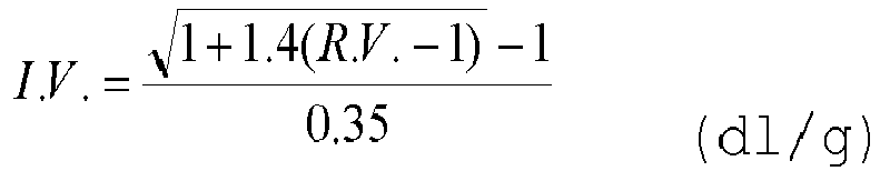
Die Viskosität des Polyesters kann entweder als intrinsische Viskosität (IV) oder als mittleres Molekulargewicht (Zahlenmittel: Mn) angegeben sein. Zur Umrechnung eines IV-Wertes gemessen in Phenol : Dichlormethan = 1: 1 in das mittlere Molekulargewicht wird die Gleichung ![]()
![]()
Diese Gleichung ist allgemein auf publizierte Daten anwendbar, wenn nicht explizit ein anderes Lösemittelgemisch und die dazu gehörenden Umrechnungsfaktoren gegeben sind.This equation is generally applicable to published data unless another solvent mixture and the associated conversion factors are explicitly given.
Erfindungsgemäss bevorzugt durchfliessen die Polykondensatgranulate den zweiten Behandlungsraum im Wesentlichen von oben nach unten, während der zweite Behandlungsraum im Gegenstrom oder alternativ im Kreuzstrom oder im Gleichstrom von einem Prozessgas durchströmt wird. Die Bewegung der Polymerteilchen im Kristallisator erfolgt durch mechanische Bewegung oder vorzugsweise durch den Strom aus Prozessgas.According to the invention, the polycondensate granules preferably flow through the second treatment space essentially from top to bottom, while the second treatment space is flowed through by a process gas in countercurrent or alternatively in crossflow or in cocurrent. The movement of the polymer particles in the crystallizer occurs through mechanical movement or preferably through the stream of process gas.
Als Prozessgase können zum Beispiel Luft, Wasserdampf oder Inertgase wie Stickstoff oder CO2 zum Einsatz kommen. Das Prozessgas kann ein Gemisch mehrerer Prozessgase umfassen. Das Prozessgas kann Additive enthalten, die entweder reaktiv auf das zu behandelnde Polykondensat einwirken, eine Quellwirkung auf das Polykondensat haben oder sich passiv auf dem zu behandelnden Polykondensatgranulaten ablagern.For example, air, water vapor or inert gases such as nitrogen or CO 2 can be used as process gases. The process gas can comprise a mixture of several process gases. The process gas can contain additives that either have a reactive effect on the polycondensate to be treated, have a swelling effect on the polycondensate or are passively deposited on the polycondensate granules to be treated.
Der erfindungsgemässe Kristallisator wird als Wirbelbett betrieben. Mit anderen Worten liegen im gesamten zweiten Behandlungsraum oder zumindest in einem Teilbereich des zweiten Behandlungsraums, welcher vom Kristallisator bereitgestellt wird, die Bedingungen eines Wirbelbetts vor.The crystallizer according to the invention is operated as a fluidized bed. In other words, the conditions of a fluidized bed exist in the entire second treatment room or at least in a portion of the second treatment room, which is provided by the crystallizer.
Als Wirbelbett wird eine Schüttung von Feststoffpartikeln bezeichnet, welche durch eine aufwärtsgerichtete Strömung eines Fluids in einen fluidisierten Zustand versetzt wird. Fliesbett und Sprudelbett sind Ausführungen des Wirbelbetts, die aufgrund unterschiedlicher Fluiddurchströmung unterschiedliche Verwirbelungsintensität ergeben.A fluidized bed is a bed of solid particles that is brought into a fluidized state by an upward flow of fluid. Fluid bed and bubble bed are versions of the fluidized bed that result in different turbulence intensity due to different fluid flows.
Der zweite Behandlungsraum ist von einem Gehäuse umgeben. Der horizontale Querschnitt des Behandlungsraumes kann eine beliebige Form aufweisen, ist bevorzugterweise aber rund oder rechteckig. Der Behandlungsraum ist bevorzugt im Wesentlichen vertikal angeordnet, so dass das Granulat die Vorrichtung von oben nach unten durchfliessen kann. Wichtig ist dabei, dass ein gleichmässiger Produktfluss erreicht werden kann. Der zweite Behandlungsraum ist seitlich durch einen Mantel begrenzt. Die Mantelwand kann dabei aus zylindrischen, konischen oder aus einer Kombination aus konischen und zylindrischen Segmenten bestehen, wodurch sich die Gasgeschwindigkeitsverteilung über die Höhe der Vorrichtung beeinflussen lässt. Eine Aufweitung im Deckenbereich erlaubt dabei eine Reduktion der Gasgeschwindigkeit, was den Austrag von Granulat verhindert. Eine Verengung im Deckenbereich erlaubt eine Erhöhung der Gasgeschwindigkeit, was zu einer stärkeren Verwirbelung führt, wodurch sich allfällige Verklebungen verhindern lassen.The second treatment room is surrounded by a housing. The horizontal cross section of the treatment room can have any shape, but is preferably round or rectangular. The treatment room is preferably arranged essentially vertically, so that the granules can flow through the device from top to bottom. It is important that a consistent product flow can be achieved. The second treatment room is bordered on the side by a jacket. The jacket wall can consist of cylindrical, conical or a combination of conical and cylindrical segments, which allows the gas velocity distribution to be influenced over the height of the device. An expansion in the ceiling area allows the gas velocity to be reduced, which prevents the discharge of granules. A narrowing in the ceiling area allows the gas velocity to increase, which leads to greater turbulence, which can prevent any adhesions.
Eine besondere Ausführungsform der vorliegenden Erfindung sieht einen wenigstens annähernd rotationssymmetrischen Gehäusemantel vor, was fertigungstechnische Vorteile sowie Vorteile für einen regelmässigen Produktfluss ergibt.A special embodiment of the present invention provides an at least approximately rotationally symmetrical housing jacket, which results in manufacturing advantages as well as advantages for a regular product flow.
Im Innern des zweiten Behandlungsraumes können Verdrängungskörper angeordnet sein, die nicht vom Granulat durchflössen werden und somit den zweiten Behandlungsraum verkleinern. Solche Verdrängungskörper können zum Beispiel zur Durchführung von Prozessgas, zur Anpassung der freien Querschnittsfläche oder zur Verbesserung des Granulatflusses eingesetzt werden.Displacement bodies can be arranged inside the second treatment room, which are not flowed through by the granules and thus reduce the size of the second treatment room. Such displacement bodies can be used, for example, to pass through process gas, to adjust the free cross-sectional area or to improve the flow of granules.
Im Innern des zweiten Behandlungsraumes können Trennwände angeordnet sein, die den zweiten Behandlungsraum in zwei oder mehrere Kammern unterteilen, wobei die Kammern durch Durchlassöffnungen für die Granulate miteinander verbunden sind.Partition walls can be arranged inside the second treatment room, which divide the second treatment room into two or more chambers, the chambers being connected to one another by passage openings for the granules.
Bevorzugt mündet zumindest eine Einfüllöffnung in den Deckenbereich des zweiten Behandlungsraumes und ermöglicht das Einführen des zu behandelnden Granulats in den zweiten Behandlungsraum. Bei der Einfüllöffnung kann es sich zum Beispiel um eine Öffnung im Gehäuse oder um den Austritt aus einem Rohr, das in das Gehäuse geführt wird, handeln. Die Einfüllöffnung kann in mehrere Segmente unterteilt sein, was eine Verteilung der Granulate im Behandlungsraum erlaubt.Preferably, at least one filling opening opens into the ceiling area of the second treatment room and enables the granules to be treated to be introduced into the second treatment room. The filling opening can be, for example, an opening in the housing or the outlet from a pipe that is led into the housing. The filling opening can be divided into several segments, which allows the granules to be distributed in the treatment room.
Bevorzugt mündet zumindest eine Austragsöffnung in den unteren Teil des zweiten Behandlungsraumes, durch die behandeltes Granulat aus dem Behandlungsraum ausgetragen werden kann. Bei der Austragsöffnung kann es sich zum Beispiel um eine Öffnung im Gehäuse oder um den Eintritt in ein Rohr, das aus dem Gehäuse heraus geführt wird, handeln. Üblicherweise wird das Granulat durch einen konischen Bereich der Austragsöffnung zugeführt. Der Winkel des Auslaufkonus beträgt zur Horizontalen bevorzugterweise 50 - 80°, wenn das Granulat im Austragskonus nicht fluidisiert oder vibriert wird, und 15 - 60°, insbesondere 30 - 50°, wenn das Granulat im Austragskonus fluidisiert oder vibriert wird. Alternativ kann das Granulat auch mittels einer mechanischen Austragsvorrichtung, wie zum Beispiel einer Schnecke, der Austragsöffnung zugeführt werden.At least one discharge opening preferably opens into the lower one Part of the second treatment room through which treated granules can be discharged from the treatment room. The discharge opening can be, for example, an opening in the housing or the entry into a pipe that is led out of the housing. The granules are usually fed through a conical area of the discharge opening. The angle of the outlet cone to the horizontal is preferably 50 - 80 ° if the granules in the discharge cone are not fluidized or vibrated, and 15 - 60 °, in particular 30 - 50 °, if the granules in the discharge cone are fluidized or vibrated. Alternatively, the granules can also be fed to the discharge opening using a mechanical discharge device, such as a screw.
Unterhalb der Austragsöffnung befindet sich erfindungsgemäss bevorzugt eine Absperreinheit, vorzugsweise eine Schleuseneinheit, wie zum Beispiel eine Zellradschleuse, oder eine Walzeneinheit mit deren Hilfe der Granulatabfluss aus dem Behandlungsraum geregelt wird. Als Regelgrösse kann dabei zum Beispiel die Füllhöhe des Granulates im Behandlungsraum oder das Gewicht der Granulate in der Vorrichtung dienen.According to the invention, below the discharge opening there is preferably a shut-off unit, preferably a lock unit, such as a rotary valve, or a roller unit with the help of which the outflow of granules from the treatment room is regulated. For example, the filling height of the granules in the treatment room or the weight of the granules in the device can serve as a control variable.
Diese Absperreinheit, vorzugsweise Schleuseneinheit, ist mit einem Gehäuse und einem darin beweglich angeordneten Rotor ausgestattet, wobei die Absperreinheit, vorzugsweise Schleuseneinheit, einen Spalt zwischen dem Rotor und dem Gehäuse aufweist, welcher grösser ist als der mittlere Granulatdurchmesser.This shut-off unit, preferably a lock unit, is equipped with a housing and a rotor movably arranged therein, the shut-off unit, preferably a lock unit, having a gap between the rotor and the housing which is larger than the average granule diameter.
Durch die Tatsache, dass in einem Wirbelbett (Fliessbett oder Sprudelbett) mit derart kurzer Verweilzeit wie erfindungsgemäss definiert ein Anteil von Granulaten mit geringer Kristallinität (welche sehr weich und verformbar sind) auftreten kann, ergibt sich das Problem, dass in einer anschliessenden Absperreinheit, die den Austrag von Granulat aus dem Wirbelbett regelt (und die somit immer ganz mit Granulat gefüllt ist), ein Teil der weichen Granulate zerquetscht werden kann. Dieses Problem wird erfindungsgemäss bevorzugt dadurch gelöst, dass der Austrag nach unten durch eine Absperreinheit, vorzugsweise Schleuseneinheit, mit grösserem Toleranzbereich erfolgt. Durch die Bereitstellung eines Spalts zwischen dem Rotor und dem Gehäuse, welcher grösser ist als der mittlere Granulatdurchmesser, wird ein Zerquetschen von Granulat in der Absperreinheit, vorzugsweise Schleuseneinheit, verringert oder vollständig unterbunden.The fact that a proportion of granules with low crystallinity (which are very soft and deformable) can occur in a fluidized bed (fluid bed or bubble bed) with such a short residence time as defined according to the invention results in the problem that in a subsequent shut-off unit, which regulates the discharge of granules from the fluidized bed (and which is therefore always completely filled with granules), some of the soft granules can be crushed. According to the invention, this problem is preferably solved in that the downward discharge takes place through a shut-off unit, preferably a lock unit, with a larger tolerance range. By providing a gap between the rotor and the housing, which is larger than the average granule diameter, crushing of granules in the shut-off unit, preferably the lock unit, is reduced or completely prevented.
Durch den Einsatz einer derartigen Absperreinheit, vorzugsweise Schleuseneinheit, mit grossem Toleranzbereich kann allerdings das Problem auftreten, dass der Kristallisator mit dem zweiten Behandlungsraum an diesem Auslass keine zuverlässige Gassperre mehr aufweist. Dies kann für bestimmte Anwendungen ein erheblicher Nachteil sein.However, by using such a shut-off unit, preferably a lock unit, with a large tolerance range, the problem can arise that the crystallizer with the second treatment chamber no longer has a reliable gas barrier at this outlet. This can be a significant disadvantage for certain applications.
Zur Lösung dieses Problems ist gemäss einer bevorzugten Ausführungsform der vorliegenden Erfindung stromabwärts von der vorstehend beschriebenen Absperreinheit, vorzugsweise Schleuseneinheit, mit grossem Toleranzbereich eine zweite Absperreinheit, vorzugsweise Schleuseneinheit, mit einem Gehäuse und einem darin beweglich angeordneten Rotor angeordnet, welche einen Spalt zwischen dem Rotor und dem Gehäuse aufweist, der kleiner ist als der mittlere Granulatdurchmesser. Diese zweite Absperreinheit, vorzugsweise Schleuseneinheit, kann aufgrund ihrer Grösse und gegebenenfalls aufgrund ihrer Drehzahl nicht vollständig mit Granulat befüllt werden und somit kein Granulat einklemmen beziehungsweise zerquetschen. Andererseits stellt diese zweite Absperreinheit, vorzugsweise Schleuseneinheit, aufgrund ihrer Dimension eine zuverlässige Gassperre bereit. Der Toleranzbereich der zweiten Absperreinheit beträgt dabei bevorzugt zwischen 0.05 und 1 mm.To solve this problem, according to a preferred embodiment of the present invention, a second shut-off unit, preferably a lock unit, with a housing and a rotor movably arranged therein, is arranged with a large tolerance range downstream of the shut-off unit described above, preferably a lock unit, which creates a gap between the rotor and the housing which is smaller than the average granulate diameter. This second shut-off unit, preferably a lock unit, cannot be completely filled with granules due to its size and possibly due to its speed and therefore cannot trap or crush any granules. On the other hand, this second shut-off unit, preferably a lock unit, provides a reliable gas barrier due to its dimensions. The tolerance range of the second shut-off unit is preferably between 0.05 and 1mm.
Im Bodenbereich des Behandlungsraumes befindet sich vorzugsweise zumindest eine Zufuhreinrichtung für ein Prozessgas. Die Zufuhreinrichtung weist zumindest eine Eintrittsöffnung auf, durch die Prozessgas in den zweiten Behandlungsraum strömt.In the floor area of the treatment room there is preferably at least one supply device for a process gas. The supply device has at least one inlet opening through which process gas flows into the second treatment room.
Die Zuführeinrichtung für ein Prozessgas kann Vorrichtungen, wie zum Beispiel nach unten offene Kegel oder Dachreihen sowie Leitungen oder Bleche mit Austrittsbohrungen, umfassen, solange eine ausreichend gleichmässige Verteilung des Prozessgases erfolgt. Eine besondere Ausführung sieht vor, dass der Behandlungsraum nach unten durch eine zumindest teilweise gasdurchlässige Absperreinrichtung, insbesondere ein Lochblech mit einer Vielzahl an Eintrittsöffnungen, begrenzt wird, die von Prozessgas zumindest stellenweise, nicht aber von den Granulaten durchströmt werden kann. Dazu sind die Öffnungen kleiner als der Durchmesser der Granulate. Die Durchlassfläche weist bevorzugterweise zwischen 1% und 30% auf. Bevorzugt sind Öffnungen zwischen 20 und 90%, insbesondere zwischen 30 und 80% des Durchmessers der Granulate. Die Anzahl, Grösse und Anordnung der Öffnungen kann dabei gleichmässig oder ungleichmässig sein. Die Absperreinrichtung ist konisch oder horizontal angeordnet.The supply device for a process gas can include devices such as cones or rows of roofs that are open at the bottom, as well as lines or sheets with outlet holes, as long as the process gas is distributed sufficiently evenly. A special embodiment provides that the treatment space is delimited at the bottom by an at least partially gas-permeable shut-off device, in particular a perforated plate with a large number of inlet openings, through which process gas can flow at least in places, but not by the granules. The openings are smaller than the diameter of the granules. The passage area preferably has between 1% and 30%. Openings between 20 and 90%, in particular between 30 and 80%, of the diameter of the granules are preferred. The number, size and arrangement of the openings can be uniform or uneven. The shut-off device is arranged conically or horizontally.
Unterhalb der Absperreinrichtung kann sich ein Verteilerraum befinden, durch den Prozessgas zur Absperreinrichtung geführt wird. In diesen Verteilerraum mündet zumindest eine Zufuhröffnung für Prozessgas. Weiterhin können Vorrichtungen zur Verteilung des Prozessgases, wie Staubleche, Ventile oder Klappen, wie auch getrennte Kanäle zur individuellen Prozessgaszufuhr angeordnet sein. Alternativ kann der Behandlungsraum nach unten durch eine nicht gasdurchlässige Absperreinrichtung begrenzt sein. In diesem Fall kann es sich bei der zumindest einen Zufuhreinrichtung für ein Prozessgas, um eine Öffnung im Gehäuse, um den Austritt aus einem Rohr oder mehreren Rohren, die in das Gehäuse geführt werden, oder um ein einzelnes Dach oder eine Dachreihe, die entweder mit Löchern versehen oder nach unten offen sind, handeln. Dabei kann ein anfälliger Verdrängungskörper zur Gaszufuhr verwendet werden.Below the shut-off device there can be a distribution room through which process gas is led to the shut-off device. At least one supply opening for process gas opens into this distribution space. Furthermore, devices for distributing the process gas, such as baffles, valves or flaps, as well as separate channels for individual process gas supply can be arranged. Alternatively, the treatment room can be limited at the bottom by a non-gas-permeable shut-off device. In this case it can be at least one feed device for a process gas, an opening in the housing, the exit from a pipe or several pipes that are led into the housing, or a single roof or a row of roofs that are either perforated or open at the bottom. A vulnerable displacement body can be used to supply gas.
Eine besondere Ausführung der vorliegenden Erfindung sieht vor, dass zusätzlich zur zumindest einen Zuführeinrichtung für Prozessgas im Bodenbereich des zweiten Behandlungsraumes zumindest eine weitere Zufuhreinrichtung für Prozessgas in den zweiten Behandlungsraum mündet, wodurch sich eine mehrstufige Wärmezufuhr sowie ein mehrstufiges Gasgeschwindigkeitsprofil erreichen lässt.A special embodiment of the present invention provides that, in addition to the at least one feed device for process gas in the floor area of the second treatment room, at least one further feed device for process gas opens into the second treatment room, whereby a multi-stage heat supply and a multi-stage gas velocity profile can be achieved.
Im Deckenbereich des zweiten Behandlungsraumes befindet sich vorzugsweise zumindest eine Wegführeinrichtung für das Prozessgas. Bei der Wegführeinrichtung kann es sich zum Beispiel um eine Öffnung im Gehäuse oder um den Eintritt in ein Rohr, das aus dem Gehäuse heraus geführt wird, handeln. Die Wegführeinrichtung kann sich dabei im Mantel oder der Decke des Behandlungsraumes befinden. Gemäss einer alternativen Ausführungsform der Erfindung ist keine derartige Wegführeinrichtung vorgesehen. In diesem Fall verlässt das Prozessgas den zweiten Behandlungsraum durch die Verbindungsleitung vom ersten zum zweiten Behandlungsraum.In the ceiling area of the second treatment room there is preferably at least one removal device for the process gas. The removal device can be, for example, an opening in the housing or the entry into a pipe that is led out of the housing. The removal device can be located in the jacket or the ceiling of the treatment room. According to an alternative embodiment of the invention, no such removal device is provided. In this case, the process gas leaves the second treatment room through the connecting line from the first to the second treatment room.
In oder unterhalb der Wegführeinrichtung können sich Vorrichtungen befinden, die den Durchtritt von Prozessgas erlauben, den Durchtritt von Granulaten aber behindern. Dies kann zum Beispiel durch einen gebogenen oder umgelenkten Durchflusskanal oder mit Hilfe von ablenkenden Einbauten, wie zum Beispiel einem ZickZack-Abscheider, erfolgen.There can be devices in or below the removal device that allow the passage of process gas but hinder the passage of granules. This can be done, for example, through a curved or diverted flow channel or with the help of deflecting fixtures such as a zigzag separator.
Das Granulat wird im zweiten Behandlungsraum durch Energiezufuhr von aussen mit Hilfe des heissen Prozessgases erhitzt. Hierbei wird das Prozessgas mit einer Temperatur TGas in den zweiten Behandlungsraum geführt, die grösser ist als die Summe der Granulattemperatur TGR und der durch freigesetzte Kristallisationswärme im zweiten Behandlungsraum auftretenden Temperaturerhöhung TKR, d.h. TGas > (TGR + TKR) . Die Gastemperatur TGas liegt also über der mittleren Granulattemperatur, welche die Polykondensatgranulate ohne Energiezufuhr von aussen im zweiten Behandlungsraum erreichen würden, woraus sich der Vorteil ergibt, dass sich die Polykondensatgranulate auf eine konstante und definierte Austrittstemperatur einstellen lassen. Es hat sich erfindungsgemäss gezeigt, dass zum Erhalt eines homogen kristallisierten Polykondensats die Energiezufuhr von aussen unter Berücksichtigung der durch freigesetzte Kristallisationswärme im zweiten Behandlungsraum auftretenden Temperaturerhöhung TKR zu erfolgen hat.The granules are heated in the second treatment room by supplying energy from outside using the hot process gas. Here, the process gas is fed into the second treatment room at a temperature T gas , which is greater than the sum of the granulate temperature T GR and the temperature increase T KR occurring in the second treatment room due to the heat of crystallization released, ie T gas > (T GR + T KR ). The gas temperature T Gas is therefore above the average granulate temperature that the polycondensate granules would reach in the second treatment room without external energy supply, which has the advantage that the polycondensate granules can be set to a constant and defined outlet temperature. According to the invention, it has been shown that in order to obtain a homogeneously crystallized polycondensate, the energy supply must take place from outside, taking into account the temperature increase T KR that occurs in the second treatment room due to the heat of crystallization released.
Gemäss einer bevorzugen Ausführungsform der vorliegenden Erfindung wird das Verhältnis X der Massenströme von Gas (mG) und Granulat (mP) (X = mG/mP) im zweiten Behandlungsraum so eingestellt, dass 1 ≤ (TGas - TKR - TGR) * X ≤ 80, vorzugsweise 2 < (TGas - TKR - TGR) * X ≤ 80, besonders bevorzugt 4 < (TGas - TKR - TGR) * X ≤ 80 ist. Damit wird ein Polykondensat mit besonders vorteilhaften Eigenschaften hinsichtlich homogener Kristallisation erhalten.According to a preferred embodiment of the present invention, the ratio T GR ) * X ≤ 80, preferably 2 < (T Gas - T KR - T GR ) * This results in a polycondensate with particularly advantageous properties in terms of homogeneous crystallization.
Durch die Zunahme der Kristallinität wird Kristallisationswärme freigesetzt. Aufgrund dieser Kristallisationswärme erfolgt eine Temperaturerhöhung TKR, die sich aus der freigesetzten Wärmemenge geteilt durch die spezifische Wärmekapazität des Polykondensates ergibt.The increase in crystallinity releases heat of crystallization. Due to this heat of crystallization, a temperature increase T KR occurs, which results from the amount of heat released divided by the specific heat capacity of the polycondensate.
Im Allgemeinen liegt die durch freigesetzte Kristallisationswärme im zweiten Behandlungsraum auftretende Temperaturerhöhung TKR im Bereich von 5°C bis 40°C. Insbesondere im Fall von Polyethylenterephthalat (PET) liegt TKR im Bereich von 10°C bis 30°C.In general, the temperature increase T KR that occurs due to the heat of crystallization released in the second treatment room is in the range of 5°C to 40°C. Particularly in the case of polyethylene terephthalate (PET), T KR is in the range of 10°C to 30°C.
Das Granulat wird erfindungsgemäss bevorzugt im zweiten Behandlungsraum (d.h. im Kristallisator) auf eine Temperatur erhitzt, die 30°C oder mehr unter dem Schmelzpunkt des Polykondensates liegt. Im Fall von Polyethylenterephthalat (PET) wird das Granulat erfindungsgemäss bevorzugt im zweiten Behandlungsraum (d.h. im Kristallisator) auf eine Temperatur im Bereich von 140 bis 220°C, insbesondere bevorzugt auf 150 °C bis 190°C erhitzt.According to the invention, the granules are preferably heated in the second treatment room (i.e. in the crystallizer) to a temperature which is 30 ° C or more below the melting point of the polycondensate. In the case of polyethylene terephthalate (PET), according to the invention, the granules are preferably heated in the second treatment room (i.e. in the crystallizer) to a temperature in the range from 140 to 220 ° C, particularly preferably to 150 ° C to 190 ° C.
Erfindungsgemäss bevorzugt beträgt die Verweilzeit des Materials 1 bis 30 Kristallisationshalbwertszeiten. Im Fall eines schnell kristallisierenden Polymers wie Polyethylenterephthalat (PET) mit einem Comonomergehalt von weniger als 5% beträgt die Verweilzeit somit 1 bis 30 Minuten, vorzugsweise 1 bis 15 Minuten, besonders bevorzugt 1 bis 8 Minuten. Langsam kristallisierende Polymere müssen entsprechend länger im zweiten Behandlungsraum verweilen, bis der gewünschte Anstieg des Kristallisationsgrades erreicht ist.According to the invention, the residence time of the material is preferably 1 to 30 crystallization half-lives. In the case of a rapidly crystallizing polymer such as polyethylene terephthalate (PET) with a comonomer content of less than 5%, the residence time is therefore 1 to 30 minutes, preferably 1 to 15 minutes, particularly preferably 1 to 8 minutes. Polymers that crystallize slowly must remain in the second treatment room for a longer period of time until the desired increase in the degree of crystallization is achieved.
Erfindungsgemäss bevorzugt erfolgt die Kristallisation im Kristallisator im Unterschied zu herkömmlichen Verfahren mit einem Inertgas als Prozessgas. Vorzugsweise wird Stickstoff verwendet. Dabei soll der Sauerstoffgehalt des Gases im zweiten Behandlungsraum weniger als 1 Gew.-%, vorzugsweise weniger als 0,5 Gew.-% und besonders bevorzugt weniger als 0,1 Gew.-% betragen, um eine oxidative Beschädigung des Materials unter den Bedingungen der Kristallisation zu verringern beziehungsweise auszuschliessen.According to the invention, crystallization preferably takes place in the crystallizer, in contrast to conventional processes, with an inert gas as the process gas. Nitrogen is preferably used. The oxygen content of the gas in the second treatment room should be less than 1% by weight, preferably less than 0.5% by weight and particularly preferably less than 0.1% by weight, in order to avoid oxidative damage to the material under the conditions to reduce or eliminate crystallization.
Da erhitzte Prozessgase teuer sind, wird erfindungsgemäss bevorzugt das im Kristallisator eingesetzte Prozessgas zumindest teilweise in einem Kreislaufsystem geführt, wobei jeweils eine geringe Menge an Austauschgas zu- und weggeführt werden kann. Zwischen der Wegführeinrichtung und Zufuhreinrichtung für das Prozessgas besteht gemäss dieser bevorzugten Ausführungsform ein geschlossener Kreislauf aus Rohrleitungen.Since heated process gases are expensive, according to the invention, the process gas used in the crystallizer is preferably at least partially routed in a circulation system, whereby a small amount of replacement gas can be fed in and removed. According to this preferred embodiment, there is a closed circuit of pipes between the removal device and the supply device for the process gas.
Im Kreislauf können sich weitere Einheiten, wie zum Beispiel Verdichtungseinrichtungen (z. B. Ventilatoren, Gebläse oder Kompressoren), Wärmetauscher (z.B. Erhitzer), Absperrvorrichtungen z.B. ein Ventil oder Hahn) oder Reinigungseinrichtungen (z. B. Filter, Zyklone, Wäscher oder katalytische Verbrennungseinrichtungen), befinden. Da ein Grossteil der Verdichtungsenergie als Wärme in den Gasstrom übergeht, kann die erhöhte Prozessgastemperatur auch mit wenig zusätzlicher Erhitzerleistung aufrecht erhalten werden. Verändert sich jedoch die Eintrittstemperatur der Polykondensatgranulate, so kann dies mittels der zusätzlichen Erhitzerleistung ausgeglichen werden. Erfindungsgemäss bevorzugt sind in dem geschlossenen Kreislaufsystem zusätzliche Einheiten enthalten, ausgewählt aus der Gruppe bestehend aus einem Ventilator, einem Wärmetauscher wie Erhitzer, einer Absperrvorrichtung, einen Kondensator oder einer Kombination dieser Einheiten.There may be other units in the circuit, such as compression devices (e.g. fans, blowers or compressors), heat exchangers (e.g. heaters), shut-off devices such as a valve or tap) or cleaning devices (e.g. filters, cyclones, scrubbers or catalytic combustion facilities). Since a large part of the compression energy is transferred to the gas stream as heat, the increased process gas temperature can be maintained even with little additional heater power. However, if the inlet temperature of the polycondensate granules changes, this can be compensated for using the additional heater power. According to the invention, the closed circuit system preferably contains additional units selected from the group consisting of a fan, a heat exchanger such as a heater, a shut-off device, a condenser or a combination of these units.
Gemäss einer bevorzugten Ausführungsform der vorliegenden Erfindung ist der Kristallisator, vorzugsweise durch eine Zufuhrleitung, mit einem Inertgastank verbunden. Durch die Zuführleitung kann Inertgas aus dem Inertgastank in das Kreislaufsystem aus Rohrleitungen oder direkt in den Kristallisator eingeführt werden. Vorzugsweise ist in dieser Zuführleitung eine Dosiereinheit, beispielsweise ein Regelventil, angeordnet, mit welcher die Zufuhr von Inertgas kontrolliert werden kann.According to a preferred embodiment of the present invention, the crystallizer is connected to an inert gas tank, preferably via a supply line. Through the supply line, inert gas can be introduced from the inert gas tank into the circulation system of pipelines or directly into the crystallizer. Preferably, a metering unit, for example a control valve, is arranged in this supply line, with which the supply of inert gas can be controlled.
Gemäss einer bevorzugten Ausführungsform der vorliegenden Erfindung wird der Druck p2 im zweiten Behandlungsraum so eingestellt, dass er oberhalb des im ersten Behandlungsraum vorliegenden Druckes p1 liegt. Dadurch wird ein Übergehen von Kühlmedium aus dem ersten Behandlungsraum im Trockner in den zweiten Behandlungsraum im Kristallisator verhindert. Aufgrund des höheren Drucks im zweiten Behandlungsraum geht hierbei Inertgas aus dem zweiten Behandlungsraum in den ersten Behandlungsraum über. Es hat sich jedoch gezeigt, dass es gemäss einer erfindungsgemäss bevorzugten Ausführungsform ausreichend ist, wenn p1 < p2 < p1 +100 mbar, vorzugsweise p1 < p2 < p1 +50 mbar gilt, d.h. der Druck im zweiten Behandlungsraum weniger als 100 mbar, vorzugsweise sogar weniger als 50 mbar über dem Druck im ersten Behandlungsraum liegt. Mit anderen Worten genügt überraschend ein leicht höherer Druck im zweiten Behandlungsraum gegenüber dem ersten Behandlungsraum. Bei diesen Druckverhältnissen geht nur ein geringer Anteil an Inertgas durch Übertritt in den ersten Behandlungsraum verloren. Dieser kleine Nachteil wird durch die sich aus der im Kristallisator vorliegenden geringen Feuchtigkeit und den sich daraus ergebenden apparativen und verfahrenstechnischen Vorteilen (geringere Menge an Inertgas im Kristallisator erforderlich, Inertgas muss nur wenig beziehungsweise überhaupt nicht getrocknet werden) mehr als ausgeglichen.According to a preferred embodiment of the present invention, the pressure p2 in the second treatment room is set so that it is above the pressure p1 present in the first treatment room. This prevents cooling medium from transferring from the first treatment room in the dryer to the second treatment room in the crystallizer. Due to the higher pressure in the second treatment room, inert gas passes from the second treatment room into the first treatment room. However, it has been shown that, according to a preferred embodiment according to the invention, it is sufficient if p1 < p2 < p1 +100 mbar, preferably p1 < p2 < p1 +50 mbar, i.e. the pressure in the second treatment room is less than 100 mbar, preferably even is less than 50 mbar above the pressure in the first treatment room. In other words, a slightly higher pressure in the second treatment room compared to the first treatment room is surprisingly sufficient. At these pressure conditions, only a small proportion of inert gas is lost through passage into the first treatment room. This small disadvantage is more than compensated for by the low moisture present in the crystallizer and the resulting advantages in terms of equipment and process technology (smaller amount of inert gas required in the crystallizer, inert gas only needs to be dried a little or not at all).
Die erfindungsgemässe Vorrichtung umfasst gemäss einer bevorzugten Ausführungsform Sensoren, mit deren Hilfe der Druck im ersten und zweiten Behandlungsraum bestimmt werden kann. Erfindungsgemäss können herkömmliche Drucksensoren eingesetzt werden. Die Sensoren sind mit einer Steuereinheit verbunden, mit welcher die von den Sensoren ermittelten Daten ausgewertet werden können. Bei der erfindungsgemässen Steuereinheit gemäss dieser Ausführungsform handelt es sich üblicherweise um einen Computer mit erforderlichen Bauteilen wie einer zentralen Rechnereinheit (CPU) und Speicher.According to a preferred embodiment, the device according to the invention comprises sensors with the help of which the pressure in the first and second treatment rooms can be determined. According to the invention, conventional pressure sensors can be used. The sensors are connected to a control unit with which the data determined by the sensors can be evaluated. The control unit according to the invention according to this embodiment is usually a computer necessary components such as a central processing unit (CPU) and memory.
Gemäss einer erfindungsgemäss bevorzugten Ausführungsform ist die Steuereinheit vorzugsweise mit der in der Zuführleitung befindlichen Dosiereinheit verbunden und regelt durch entsprechende Kontrolle der Dosiereinheit die Menge an Prozessgas, welche dem Kreislaufsystem des Kristallisators zugeführt wird. Ermittelt die Steuereinheit beispielsweise aus den von den Sensoren übermittelten Druckwerten einen Druckanstieg im ersten Behandlungsraum, wird durch Öffnen der Dosiereinheit eine derartige Menge an Prozessgas in das Kreislaufsystem geführt, dass sich der gewünschte höhere Druck im zweiten Behandlungsraum einstellt. Analog wird bei einem Druckabfall im ersten Behandlungsraum Prozessgas durch Öffnen einer in einer separaten Ablassleitung befindlichen, ebenfalls mit der Steuereinheit verbundenen und durch diese geregelte Dosiereinheit aus dem Kreislaufsystem abgelassen, um einen zu hohen Druck im zweiten Behandlungsraum mit einhergehendem zu grossem Übergang von Prozessgas vom zweiten in den ersten Behandlungsraum zu vermeiden. Alternativ kann die gewünschte Druckdifferenz zwischen erstem und zweitem Behandlungsraum auch dadurch eingestellt werden, dass durch Öffnen entsprechender Dosiereinrichtungen die Luftzufuhr in den ersten Behandlungsraum beziehungsweise die Luftabfuhr aus dem ersten Behandlungsraum erhöht oder erniedrigt wird.According to a preferred embodiment according to the invention, the control unit is preferably connected to the metering unit located in the supply line and regulates the amount of process gas that is supplied to the circulation system of the crystallizer by appropriately controlling the metering unit. If, for example, the control unit determines a pressure increase in the first treatment room from the pressure values transmitted by the sensors, by opening the metering unit, such an amount of process gas is introduced into the circulation system so that the desired higher pressure is established in the second treatment room. Analogously, in the event of a pressure drop in the first treatment room, process gas is drained from the circuit system by opening a metering unit located in a separate discharge line, also connected to the control unit and regulated by it, in order to prevent the pressure in the second treatment room from being too high, with the associated too large a transfer of process gas from the second in the first treatment room. Alternatively, the desired pressure difference between the first and second treatment rooms can also be set by increasing or decreasing the air supply into the first treatment room or the air removal from the first treatment room by opening corresponding metering devices.
Ist die zur Einstellung eines gemäss einer erfindungsgemäss bevorzugten Ausführungsform gewünschten Überdrucks im zweiten Behandlungsraum erforderliche Menge an Inertgas bekannt oder ermittelt, kann gemäss dieser erfindungsgemäss bevorzugten Ausführungsform die Vorrichtung auch ohne Steuereinheit durch Einleiten der erforderlichen Menge an Inertgas in den Kristallisator betrieben werden. Es empfiehlt sich aber auch hier zumindest eine Kontrolle der Druckverhältnisse im ersten und zweiten Behandlungsraum mit Hilfe von Drucksensoren. Gemäss einer weiteren alternativen Ausführungsform ist kein Gasauslass aus dem zweiten Behandlungsraum vorgesehen. In diesem Fall kommt es bei Einleitung von Inertgas in den zweiten Behandlungsraum zwangsläufig zu einem erhöhten Druck im zweiten Behandlungsraum gegenüber dem ersten Behandlungsraum. Dies führt ab einem bestimmten Druckgefälle zu einem Übergang des Inertgases von den zweiten in den ersten Behandlungsraum, wodurch erfindungsgemäss bevorzugt ebenfalls das Eintragen von Wasser in den zweiten Behandlungsraum verhindert wird.If the amount of inert gas required to set a desired overpressure in the second treatment room according to a preferred embodiment according to the invention is known or determined, according to this preferred embodiment according to the invention, the device can also be operated without a control unit by introducing the required amount of inert gas into the crystallizer. But here too, at least one is recommended Control of the pressure conditions in the first and second treatment rooms using pressure sensors. According to a further alternative embodiment, no gas outlet from the second treatment room is provided. In this case, when inert gas is introduced into the second treatment room, the pressure in the second treatment room is inevitably increased compared to the first treatment room. From a certain pressure drop, this leads to a transfer of the inert gas from the second to the first treatment room, which, according to the invention, preferably also prevents the entry of water into the second treatment room.
Durch eine bevorzugte Ausführungsform der vorliegenden Erfindung wird ein Energieverlust im Kristallisator durch eine etwaige Verdampfung von Kühlmedium vom Granulat sehr klein gehalten.Through a preferred embodiment of the present invention, energy loss in the crystallizer due to any evaporation of cooling medium from the granules is kept very small.
Gemäss dieser bevorzugten Ausführungsform der vorliegenden Erfindung kann daher das Granulat mit einer geringeren Menge an Prozessgas effizient auf eine Temperatur erhitzt werden, die einer Temperatur entspricht, die in einer gegebenenfalls anschliessenden Nachbehandlungsstufe anzuwendenden ist. Erfindungsgemäss bevorzugt ist daher ein weiteres Erhitzen des Granulats in einer sich an die Kristallisation anschliessende Nachbehandlungsstufe überhaupt nicht oder nur in geringem Mass erforderlich.According to this preferred embodiment of the present invention, the granules can therefore be heated efficiently with a smaller amount of process gas to a temperature which corresponds to a temperature that is to be used in an optional subsequent post-treatment stage. According to the invention, further heating of the granules in a post-treatment stage following crystallization is therefore not required at all or only to a small extent.
Beim Austritt aus dem zweiten Behandlungsraum weist das Granulat vorzugsweise einen Kristallisationsgrad auf, der grösser ist als 35% des maximal bei dieser Kristallisationstemperatur erreichbaren Kristallisationsgrades. Insbesondere bevorzugt weist das Granulat beim Austritt aus dem zweiten Behandlungsraum einen Kristallisationsgrad auf, der zwischen 40% und 70% des maximal bei der Kristallisationstemperatur erreichbaren Kristallisationsgrades liegt. Im Fall von Polyethylenterephthalat (PET) weist das Granulat beim Austritt aus dem zweiten Behandlungsraum einen Kristallisationsgrad zwischen 20% und 50%, insbesondere zwischen 30% und 40% auf.When exiting the second treatment room, the granules preferably have a degree of crystallization that is greater than 35% of the maximum degree of crystallization that can be achieved at this crystallization temperature. Particularly preferably, the granules have a degree of crystallization upon exiting the second treatment room that is between 40% and 70% of the maximum degree of crystallization that can be achieved at the crystallization temperature lies. In the case of polyethylene terephthalate (PET), the granules have a degree of crystallization between 20% and 50%, in particular between 30% and 40%, when exiting the second treatment room.
Gemäss der vorliegenden Erfindung kann das nach der Kristallisation erhaltene Material einer weiteren thermischen Behandlungsstufe zugeführt werden, welche vorzugsweise aus der Gruppe bestehend aus einer Devolatilisierungsstufe, vorzugsweise Dealdehydisierungsstufe, und einer Festphasen-Nachkondensation (SSP) ausgewählt ist. Diese thermische Behandlungsstufe wird in einem dritten Behandlungsraum durchgeführt, welcher sich vorzugsweise in einem separaten Reaktor befindet.According to the present invention, the material obtained after crystallization can be fed to a further thermal treatment stage, which is preferably selected from the group consisting of a devolatilization stage, preferably dealdehydization stage, and a solid phase post-condensation (SSP). This thermal treatment stage is carried out in a third treatment room, which is preferably located in a separate reactor.
Sowohl die Devolatliisierung, vorzugsweise Dealdehydisierung, als auch die SSP-Reaktion sind dem Fachmann bekannt und müssen an dieser Stelle nicht näher erläutert werden. Erfindungsgemäss bevorzugt wird diese thermische Behandlung in einem dritten Behandlungsraum in einer Gasphase aus Inertgas durchgeführt, wobei flüchtige Komponenten aus dem Polymer während der Behandlung verdampfen und in die Gasphase übergehen. Vorzugsweise wird Stickstoff als Inertgas verwendet. Erfindungsgemäss soll der Sauerstoffgehalt des Gases im dritten Behandlungsraum weniger als 0,1 Gew.-%, vorzugsweise weniger als 0,05 Gew.-% und besonders bevorzugt weniger als 0,02 Gew.-% betragen, um eine oxidative Beschädigung des Materials unter den Bedingungen der Kristallisation zu verringern beziehungsweise auszuschliessen.Both the devolatliization, preferably dealdehydization, and the SSP reaction are known to those skilled in the art and do not need to be explained in more detail here. According to the invention, this thermal treatment is preferably carried out in a third treatment room in a gas phase made of inert gas, with volatile components from the polymer evaporating during the treatment and passing into the gas phase. Nitrogen is preferably used as an inert gas. According to the invention, the oxygen content of the gas in the third treatment room should be less than 0.1% by weight, preferably less than 0.05% by weight and particularly preferably less than 0.02% by weight, in order to avoid oxidative damage to the material to reduce or exclude the conditions of crystallization.
Aufgrund der hohen Temperatur des in den dritten Behandlungsraum eintretenden Polymers ist es nicht erforderlich, sehr heisses Prozessgas in den dritten Behandlungsraum einzuleiten. Aufgrund frei werdender Kristallisationswärme wird erfindungsgemäss im dritten Behandlungsraum im Fall von Polyethylenterephthalat (PET) in der Regel ein Temperaturanstieg von 3 bis 15 °C, vorzugsweise von 5 bis 15°C und besonders bevorzugt von 7 bis 15°C beobachtet. Gemäss der vorliegenden Erfindung kann daher in bestimmten Fällen in den dritten Behandlungsraum ein Prozessgas eingeleitet werden, dessen Temperatur unterhalb der Temperatur der im dritten Behandlungsraum vorliegenden Polymerteilchen liegt. Durch die vorliegende Erfindung kann eine sich anschliessende thermische Behandlungsstufe daher energieeffizient durchgeführt werden.Due to the high temperature of the polymer entering the third treatment room, it is not necessary to introduce very hot process gas into the third treatment room. Due to the heat of crystallization released, according to the invention, in the third treatment room in the case of polyethylene terephthalate (PET) usually a temperature increase of 3 to 15 ° C, preferably from 5 to 15 ° C and particularly preferably from 7 to 15 ° C is observed. According to the present invention, in certain cases a process gas can be introduced into the third treatment room, the temperature of which is below the temperature of the polymer particles present in the third treatment room. Thanks to the present invention, a subsequent thermal treatment stage can therefore be carried out in an energy-efficient manner.
Im dritten Behandlungsraum wird das Prozessgas vorzugsweise im Gegenstrom zum Strom der Polymerpartikel geführt. Es können prinzipiell die gleichen Reaktoren in der thermischen Behandlung eingesetzt werden, welche vorstehend für die Kristallisation beschrieben wurden, oder andere hierfür herkömmlich eingesetzte Reaktoren. Beispielsweise sei ein herkömmlicher Schachtreaktor erwähnt.In the third treatment room, the process gas is preferably fed in countercurrent to the flow of polymer particles. In principle, the same reactors can be used in the thermal treatment that were described above for crystallization, or other reactors conventionally used for this purpose. For example, a conventional shaft reactor should be mentioned.
Die kristallisierten Polymerteilchen werden aus dem Kristallisator auf bekannte Art in den dritten Behandlungsraum überführt. Beispielsweise können die Teilchen den Kristallisator mittels einer pneumatischen Förderung in den dritten Behandlungsraum überführt werden. Hierbei kann je nach Geschwindigkeit der Förderung im Fall von Polyethylenterephthalat (PET) eine Abkühlung der Polymerpartikel um zwischen 2 und 15°C, vorzugsweise zwischen 3 und 15°C und besonders bevorzugt zwischen 5 und 15°C erfolgen. Falls erforderlich kann ein zusätzliches Erhitzen der Teilchen vor Eintritt in den dritten Behandlungsraum auf bekannte Art durchgeführt werden.The crystallized polymer particles are transferred from the crystallizer to the third treatment room in a known manner. For example, the particles can be transferred from the crystallizer to the third treatment room using pneumatic conveyance. Depending on the speed of conveyance, in the case of polyethylene terephthalate (PET), the polymer particles can be cooled by between 2 and 15 ° C, preferably between 3 and 15 ° C and particularly preferably between 5 and 15 ° C. If necessary, additional heating of the particles can be carried out in a known manner before entering the third treatment room.
Erfindungsgemäss kann die Dealdehydisierung von beispielsweise Polyethylenterephthalat im dritten Behandlungsraum bei einer Temperatur von 140 bis 200°C erfolgen. Es ist hierbei beispielsweise ein Temperaturanstieg im dritten Behandlungsraum von 3 bis 15°C zu beobachten.According to the invention, the dealdehydization of, for example, polyethylene terephthalate can take place in the third treatment room at a temperature of 140 to 200 ° C. This is for example a temperature increase of 3 to 15°C was observed in the third treatment room.
Erfindungsgemäss kann die SSP-Reaktion von beispielsweise Polyethylenterephthalat im dritten Behandlungsraum bei einer Temperatur von 180 bis 240°C, vorzugsweise 180 bis 225°C erfolgen. Es ist hierbei beispielsweise ein Temperaturanstieg im dritten Behandlungsraum von 3 bis 15°C zu beobachten.According to the invention, the SSP reaction of, for example, polyethylene terephthalate can take place in the third treatment room at a temperature of 180 to 240 ° C, preferably 180 to 225 ° C. For example, a temperature increase of 3 to 15°C can be observed in the third treatment room.
Die vorliegende Erfindung wird nachstehend anhand einer nicht einschränkenden Zeichnung näher erläutert. Es zeigt:
- Fig. 1
- eine schematische Darstellung einer bevorzugten Ausführungsform einer Vorrichtung gemäss der vorliegenden Erfindung.
- Fig. 1
- a schematic representation of a preferred embodiment of a device according to the present invention.
Die Vorrichtung gemäss
Das geschmolzene Material wird in eine Granulationsvorrichtung 2 überführt. In der Granulationsvorrichtung 2 wird auf bekannte Weise ein Granulat aus dem geschmolzenen Material hergestellt. Beispielsweise kann es sich um einen Unterwassergranulator (wie in
Das Granulat wird über eine Verbindungsleitung 3 direkt in die Einheit zum Trocknen des Granulats (Trocknungsvorrichtung) 4 überführt. Zur Vermeidung einer zu starken Abkühlung des Granulats sollte dieses so schnell wie möglich aus dem Granulator 2 und durch die Verbindungsleitung 3 geführt werden. Vorzugsweise kann die Fliessgeschwindigkeit in der Verbindungsleitung 3 durch Einleitung eines Gasstroms (vorzugsweise Luft) erhöht werden.The granules are transferred via a connecting
In der Einheit zum Trocknen des Granulats (Trocknungsvorrichtung) 4 wird das Granulat vom flüssigen Kühlmedium (Wasser) abgetrennt und getrocknet. Das abgetrennte Kühlmedium wird über eine Rohrleitung 9a zurück in den Vorratsbehälter (Tank) 9b für das Kühlmedium geführt. Der Vorratsbehälter 9b weist einen Einlass 9e zur Zuführung von Kühlmedium auf. Vom Vorratsbehälter 9b wird das Kühlmedium mit Hilfe einer Umwälzvorrichtung (Pumpe) 9c in die Granulationsvorrichtung 2 überführt. Hierbei durchläuft das Kühlmedium vorzugsweise einen Wärmetauscher 9d. Im Wärmetauscher 9d kann das Kühlmedium nach Bedarf erwärmt oder abgekühlt werden. Insbesondere aus der Trocknungsvorrichtung 4 zurückgeführtes Kühlmedium kann aufgrund des Kontakts mit heissem Granulat eine zu hohe Temperatur aufweisen und muss vor dem Eintritt in die Granulationsvorrichtung 2 gekühlt werden.In the unit for drying the granules (drying device) 4, the granules are separated from the liquid cooling medium (water) and dried. The separated cooling medium is fed back into the storage container (tank) 9b for the cooling medium via a
Das frische Kühlmedium, das über den Einlass 9e zugeführt wird, kann ein basisches Medium oder ein pH-Puffermedium enthalten. Insbesondere ist hier die Verwendung von Wasser mit einer in einem engen Bereich eingestellten Neutralisations- oder Pufferwirkung vorgesehen. Alternativ kann die Zugabe eines basischen Mediums oder eines pH-Puffermediums auch direkt in den Kühlkreislauf, z.B. in den Vorratstank 9b, erfolgen.The fresh cooling medium supplied via the
Die Trocknung des Granulats im ersten Behandlungsraum in der Einheit 4 erfolgt neben einer mechanischen Trocknungsvorrichtung mit Hilfe von Luft oder einer im wesentlichen Luft umfassenden Gasatmosphäre bei einer Temperatur von 100 bis 200°C, vorzugsweise 120 bis 160°C. In der Vorrichtung gemäss
Das Granulat wird aus dem Trockner 4 über eine Verbindungsleitung 5 direkt in einen Kristallisator 6 überführt. Zur Vermeidung des Anhaftens und der Agglomeration von Granulatpartikeln ist die Verbindungsleitung 5 ohne Absperreinheiten ausgestaltet. Das Granulat kann ungehindert vom Trockner 4 in den Kristallisator 6 übergehen.The granules are transferred from the dryer 4 via a connecting line 5 directly into a
Im Kristallisator 6 wird das im Wesentlichen amorphe Granulat zumindest teilkristallisiert. Innerhalb des Kristallisators 6 werden die Granulatpartikel durch einen durch den Kristallisator 6 geleiteten Gasstrom in Bewegung gehalten. Innerhalb des Kristallisators 6 liegen die Bedingungen eines Wirbelbetts vor. Zusätzlich könnte im Kristallisator 6 auch eine Vorrichtung zur mechanischen Bewegung der Partikel bereitgestellt werden.In the
Die Kristallisation der Partikel erfolgt durch Energiezufuhr von aussen, wobei zur Energiezufuhr von aussen ein Prozessgas im Gegenstrom zum Granulatstrom durch den zweiten Behandlungsraum geführt wird, welches eine Temperatur TGas aufweist, die grösser ist als die Summe der Granulattemperatur TGR und der durch freigesetzte Kristallisationswärme im zweiten Behandlungsraum auftretenden Temperaturerhöhung TKR, d.h. TGas > (TGR + TKR) . Im Fall von Polyethylenterephthalat (PET) erfolgt die Kristallisation bei einer Temperatur von 140 bis 220°C, wobei bei Temperaturen über 180°C bevorzugt eine Inertgas, im wesentlichen Stickstoff, als Prozessgas verwendet wird. Das kristallisierte Granulat verlässt den Kristallisator über eine Austragsvorrichtung 7, beispielsweise einer Absperreinheit wie einer Zellradschleuse. Diese Zellradschleuse ist mit einem Gehäuse und einem darin beweglich angeordneten Rotor ausgestattet, welche einen Spalt zwischen dem Rotor und dem Gehäuse aufweist, welcher grösser ist als der mittlere Granulatdurchmesser.The crystallization of the particles takes place by supplying energy from the outside, with a process gas being passed through the second treatment room in countercurrent to the stream of granules in order to supply energy from the outside, which has a temperature T gas which is greater than the sum of the granulate temperature T GR and the heat of crystallization released by it Temperature increase T KR occurring in the second treatment room, ie T Gas > (T GR + T KR ). In the case of polyethylene terephthalate (PET), crystallization takes place at a temperature of 140 to 220 ° C, with an inert gas, essentially nitrogen, preferably being used as the process gas at temperatures above 180 ° C. The crystallized granules leave the crystallizer via a
Alternativ kann stromabwärts von der Zellradschleuse eine zweite Schleuseneinheit (wie eine Zellradschleuse) mit einem Gehäuse und einem darin beweglich angeordneten Rotor angeordnet sein, welche einen Spalt zwischen dem Rotor und dem Gehäuse aufweist, welcher kleiner ist als der mittlere Granulatdurchmesser.Alternatively, a second lock unit (such as a rotary valve) with a housing and a rotor movably arranged therein can be arranged downstream of the rotary valve, which has a gap between the rotor and the housing that is smaller than the average granule diameter.
Die Partikel können einer anschliessenden thermischen Behandlung wie einer Dealdehydisierung oder SSP-Reaktion zugeführt werden. Wahlweise können die Partikel auch einer Kühlstufe zugeführt werden.The particles can be subjected to a subsequent thermal treatment such as a dealdehydization or SSP reaction. Optionally, the particles can also be fed to a cooling stage.
Das im Kristallisator 6 verwendete Prozessgas wird durch ein geschlossenes Kreislaufsystem aus Rohrleitungen 8a geführt. Das Prozessgas tritt in den Kristallisator 6 durch einen Einlass 6a ein und verlässt den Kristallisator 6 durch den Auslass 6b. Im Kreislaufsystem des Prozessgases befindet sich ein Ventilator 8b zur Zirkulation des Gases. Vor dem Einlass 6a ist ein Wärmetauscher 8c bereitgestellt, um das Gas vor dem Eintritt in den Kristallisator 6 auf die gewünschte Temperatur zu bringen. Vorzugsweise wird das Gas im Wärmetauscher 8c erhitzt.The process gas used in the
Im Kreislaufsystem gemäss
Weiterhin ist im Kreislaufsystem gemäss
Die Vorrichtung gemäss
Die vorliegende erfindungsgemässe Vorrichtung kann vorteilhaft zur kontinuierlichen Granulation und Kristallisation eines Polymers, insbesondere eines Polykondensats, vorzugsweise eines Polyesters wie Polyethylenterephthalat verwendet werden.The present device according to the invention can advantageously be used for the continuous granulation and crystallization of a polymer, in particular a polycondensate, preferably a polyester such as polyethylene terephthalate.
Claims (2)
Priority Applications (1)
| Application Number | Priority Date | Filing Date | Title |
|---|---|---|---|
| EP23194658.3A EP4257629A3 (en) | 2017-02-17 | 2017-02-17 | Method and device for direct crystallisation of polycondensates |
Applications Claiming Priority (2)
| Application Number | Priority Date | Filing Date | Title |
|---|---|---|---|
| EP17156629.2A EP3363841B1 (en) | 2017-02-17 | 2017-02-17 | Method and device for direct crystallisation of polycondensates |
| EP23194658.3A EP4257629A3 (en) | 2017-02-17 | 2017-02-17 | Method and device for direct crystallisation of polycondensates |
Related Parent Applications (2)
| Application Number | Title | Priority Date | Filing Date |
|---|---|---|---|
| EP17156629.2A Division EP3363841B1 (en) | 2017-02-17 | 2017-02-17 | Method and device for direct crystallisation of polycondensates |
| EP17156629.2A Division-Into EP3363841B1 (en) | 2017-02-17 | 2017-02-17 | Method and device for direct crystallisation of polycondensates |
Publications (2)
| Publication Number | Publication Date |
|---|---|
| EP4257629A2 true EP4257629A2 (en) | 2023-10-11 |
| EP4257629A3 EP4257629A3 (en) | 2024-01-10 |
Family
ID=58265754
Family Applications (2)
| Application Number | Title | Priority Date | Filing Date |
|---|---|---|---|
| EP17156629.2A Active EP3363841B1 (en) | 2017-02-17 | 2017-02-17 | Method and device for direct crystallisation of polycondensates |
| EP23194658.3A Pending EP4257629A3 (en) | 2017-02-17 | 2017-02-17 | Method and device for direct crystallisation of polycondensates |
Family Applications Before (1)
| Application Number | Title | Priority Date | Filing Date |
|---|---|---|---|
| EP17156629.2A Active EP3363841B1 (en) | 2017-02-17 | 2017-02-17 | Method and device for direct crystallisation of polycondensates |
Country Status (1)
| Country | Link |
|---|---|
| EP (2) | EP3363841B1 (en) |
Families Citing this family (4)
| Publication number | Priority date | Publication date | Assignee | Title |
|---|---|---|---|---|
| EP3650186B1 (en) | 2018-11-08 | 2023-07-19 | Polymetrix AG | Method and device for direct crystallisation of polycondensates |
| EP3708936B1 (en) | 2019-03-15 | 2024-04-17 | Polymetrix AG | Method for recycling of polyolefins |
| EP4308866A1 (en) * | 2021-03-19 | 2024-01-24 | Pegaso Industries S.p.A. | A drying process for granular polymer material and a drying plant operating according to this process |
| DE102021133419A1 (en) * | 2021-12-16 | 2023-06-22 | Maag Germany Gmbh | Process and device for processing PET polymers into PET pellets |
Citations (7)
| Publication number | Priority date | Publication date | Assignee | Title |
|---|---|---|---|---|
| US3544525A (en) | 1968-03-26 | 1970-12-01 | Allied Chem | Process for crystallization,drying and solid-state polymerization of polyesters |
| EP0541674A1 (en) | 1990-08-03 | 1993-05-19 | Eastman Kodak Co | Polymer pellet configuration for solid-state polymerization. |
| DE102004015515A1 (en) | 2004-03-28 | 2004-09-16 | Zimmer Ag | Highly crystalline polyester or copolyester in which the degree of crystallinity is controlled by latent heat crystallization, used especially for the production of food containers and drinks bottles |
| DE10349016A1 (en) | 2003-10-17 | 2005-06-16 | Bkg Bruckmann & Kreyenborg Granuliertechnik Gmbh | Thermally processing polyester pellets, e.g. polyethylene terephthalate pellets, comprises feeding polyester melt to underwater pelletizer, feeding pellets to water/solids separating device, and feeding dried pellets to agitation device |
| WO2008071023A1 (en) | 2006-12-11 | 2008-06-19 | Bühler AG | Method for producing homogeneously crystallized polycondensate pellets |
| WO2008071278A1 (en) | 2006-12-12 | 2008-06-19 | Rieter Automatik Gmbh | Method and device for producing and treating pellets |
| US7446162B2 (en) | 2000-12-07 | 2008-11-04 | Eastman Chemical Company | Polyester process using a pipe reactor |
Family Cites Families (1)
| Publication number | Priority date | Publication date | Assignee | Title |
|---|---|---|---|---|
| ES2539610T3 (en) * | 2012-09-26 | 2015-07-02 | Polymetrix Ag | Procedure and device for direct crystallization of polymers under inert gas |
-
2017
- 2017-02-17 EP EP17156629.2A patent/EP3363841B1/en active Active
- 2017-02-17 EP EP23194658.3A patent/EP4257629A3/en active Pending
Patent Citations (7)
| Publication number | Priority date | Publication date | Assignee | Title |
|---|---|---|---|---|
| US3544525A (en) | 1968-03-26 | 1970-12-01 | Allied Chem | Process for crystallization,drying and solid-state polymerization of polyesters |
| EP0541674A1 (en) | 1990-08-03 | 1993-05-19 | Eastman Kodak Co | Polymer pellet configuration for solid-state polymerization. |
| US7446162B2 (en) | 2000-12-07 | 2008-11-04 | Eastman Chemical Company | Polyester process using a pipe reactor |
| DE10349016A1 (en) | 2003-10-17 | 2005-06-16 | Bkg Bruckmann & Kreyenborg Granuliertechnik Gmbh | Thermally processing polyester pellets, e.g. polyethylene terephthalate pellets, comprises feeding polyester melt to underwater pelletizer, feeding pellets to water/solids separating device, and feeding dried pellets to agitation device |
| DE102004015515A1 (en) | 2004-03-28 | 2004-09-16 | Zimmer Ag | Highly crystalline polyester or copolyester in which the degree of crystallinity is controlled by latent heat crystallization, used especially for the production of food containers and drinks bottles |
| WO2008071023A1 (en) | 2006-12-11 | 2008-06-19 | Bühler AG | Method for producing homogeneously crystallized polycondensate pellets |
| WO2008071278A1 (en) | 2006-12-12 | 2008-06-19 | Rieter Automatik Gmbh | Method and device for producing and treating pellets |
Non-Patent Citations (1)
| Title |
|---|
| "Modern Polyesters", 2003, WILEY, pages: 158 - 104 |
Also Published As
| Publication number | Publication date |
|---|---|
| EP3363841C0 (en) | 2023-11-29 |
| EP3363841A1 (en) | 2018-08-22 |
| EP4257629A3 (en) | 2024-01-10 |
| EP3363841B1 (en) | 2023-11-29 |
Similar Documents
| Publication | Publication Date | Title |
|---|---|---|
| EP2712881B1 (en) | Method and apparatus for directly crystallisation of polymers under inert gas | |
| EP3363841B1 (en) | Method and device for direct crystallisation of polycondensates | |
| DE69631305T2 (en) | Process for the production of polylactic acid | |
| DE1905677A1 (en) | Process for crystallizing polyesters | |
| US11566104B2 (en) | Process and apparatus for direct crystallization of polycondensates | |
| EP2101972B1 (en) | Method for producing homogeneously crystallized polycondensate pellets | |
| DE60319090T2 (en) | CONTINUOUS PROCEDURE FOR SOLID PHASE POLYMERIZATION OF POLYESTERS | |
| EP1434675A1 (en) | Controlling the crystallisation of polyesters by means of the water content thereof | |
| EP2180987A2 (en) | Method for the production of polyester granules low in hydrolysis made of high-viscosity polyester melts, and device for the production of the polyester granules | |
| WO2001081450A1 (en) | Method and device for producing granulates from intermediate products of thermoplastic polyesters and copolyesters | |
| EP3865529B1 (en) | Method and device for processing a mixture of recycled polyester material and a polyester prepolymer from a polyester production process | |
| DE10042476A1 (en) | Spherical PET or PBT pellet production from polymer melt, involves production of droplets in a vibrating nozzle plate and part crystallization in a precipitation tower with opposing gas flow | |
| DE102009009957A1 (en) | Process for the production of polyester particles at high throughput in one line | |
| EP3650186B1 (en) | Method and device for direct crystallisation of polycondensates | |
| DE102007042636B4 (en) | Method and device for producing a polyester granulate according to the latent heat crystallization method | |
| DE2557580A1 (en) | PROCESS AND DEVICE FOR PRODUCING POLYCONDENSATE | |
| WO2013053571A1 (en) | Method for directly producing molded articles from polyester melts | |
| EP2671902B1 (en) | Polyamide conditioning | |
| EP2043831B1 (en) | Process for the crystallization of a slow-crystallization polymer and polymer granulate | |
| EP3283544B1 (en) | Method for crystallization and separation of low-molecular components from a granulate of a crystallizable thermoplastic material and device therefor | |
| CN114347299B (en) | Method and device for direct crystallization of polycondensates | |
| WO2005113635A1 (en) | Method for the production of polyesters | |
| DE102007026737A1 (en) | Producing a partially crystalline polymer comprises granulating melts to form particles with a core of slow-crystallizing polymer and a shell of fast-crystallizing polymer |
Legal Events
| Date | Code | Title | Description |
|---|---|---|---|
| PUAI | Public reference made under article 153(3) epc to a published international application that has entered the european phase |
Free format text: ORIGINAL CODE: 0009012 |
|
| STAA | Information on the status of an ep patent application or granted ep patent |
Free format text: STATUS: THE APPLICATION HAS BEEN PUBLISHED |
|
| AC | Divisional application: reference to earlier application |
Ref document number: 3363841 Country of ref document: EP Kind code of ref document: P |
|
| AK | Designated contracting states |
Kind code of ref document: A2 Designated state(s): AL AT BE BG CH CY CZ DE DK EE ES FI FR GB GR HR HU IE IS IT LI LT LU LV MC MK MT NL NO PL PT RO RS SE SI SK SM TR |
|
| PUAL | Search report despatched |
Free format text: ORIGINAL CODE: 0009013 |
|
| AK | Designated contracting states |
Kind code of ref document: A3 Designated state(s): AL AT BE BG CH CY CZ DE DK EE ES FI FR GB GR HR HU IE IS IT LI LT LU LV MC MK MT NL NO PL PT RO RS SE SI SK SM TR |
|
| RIC1 | Information provided on ipc code assigned before grant |
Ipc: B01J 2/30 20060101ALI20231201BHEP Ipc: C08J 3/12 20060101ALI20231201BHEP Ipc: B29B 9/16 20060101ALI20231201BHEP Ipc: C08G 69/46 20060101ALI20231201BHEP Ipc: C08G 63/88 20060101ALI20231201BHEP Ipc: C08G 63/78 20060101AFI20231201BHEP |