EP4257254A1 - Reactor device for recovering reinforcing fibers and production method for recycled reinforcing fibers - Google Patents
Reactor device for recovering reinforcing fibers and production method for recycled reinforcing fibers Download PDFInfo
- Publication number
- EP4257254A1 EP4257254A1 EP21900510.5A EP21900510A EP4257254A1 EP 4257254 A1 EP4257254 A1 EP 4257254A1 EP 21900510 A EP21900510 A EP 21900510A EP 4257254 A1 EP4257254 A1 EP 4257254A1
- Authority
- EP
- European Patent Office
- Prior art keywords
- fiber
- resin material
- reinforced resin
- reinforcing
- reinforcing fibers
- Prior art date
- Legal status (The legal status is an assumption and is not a legal conclusion. Google has not performed a legal analysis and makes no representation as to the accuracy of the status listed.)
- Pending
Links
- 239000012783 reinforcing fiber Substances 0.000 title claims abstract description 156
- 238000004519 manufacturing process Methods 0.000 title description 2
- 229920005989 resin Polymers 0.000 claims abstract description 182
- 239000011347 resin Substances 0.000 claims abstract description 182
- 239000000463 material Substances 0.000 claims abstract description 137
- 238000003825 pressing Methods 0.000 claims abstract description 79
- 238000006243 chemical reaction Methods 0.000 claims abstract description 61
- 238000011084 recovery Methods 0.000 claims abstract description 56
- 238000000034 method Methods 0.000 claims abstract description 47
- 239000002904 solvent Substances 0.000 claims abstract description 46
- 230000007246 mechanism Effects 0.000 claims abstract description 33
- 230000001105 regulatory effect Effects 0.000 claims description 14
- 229920000049 Carbon (fiber) Polymers 0.000 claims description 6
- 239000004917 carbon fiber Substances 0.000 claims description 6
- 230000006835 compression Effects 0.000 claims description 4
- 238000007906 compression Methods 0.000 claims description 4
- 239000000243 solution Substances 0.000 description 73
- 239000000126 substance Substances 0.000 description 20
- 230000004308 accommodation Effects 0.000 description 18
- 239000000835 fiber Substances 0.000 description 14
- 238000005406 washing Methods 0.000 description 12
- 239000002585 base Substances 0.000 description 10
- 239000011151 fibre-reinforced plastic Substances 0.000 description 9
- 238000002347 injection Methods 0.000 description 9
- 239000007924 injection Substances 0.000 description 9
- 229920002430 Fibre-reinforced plastic Polymers 0.000 description 8
- 230000002378 acidificating effect Effects 0.000 description 8
- LYCAIKOWRPUZTN-UHFFFAOYSA-N Ethylene glycol Chemical compound OCCO LYCAIKOWRPUZTN-UHFFFAOYSA-N 0.000 description 7
- 238000010438 heat treatment Methods 0.000 description 7
- 239000005456 alcohol based solvent Substances 0.000 description 6
- 239000004918 carbon fiber reinforced polymer Substances 0.000 description 6
- WVDDGKGOMKODPV-UHFFFAOYSA-N Benzyl alcohol Chemical compound OCC1=CC=CC=C1 WVDDGKGOMKODPV-UHFFFAOYSA-N 0.000 description 5
- 238000013019 agitation Methods 0.000 description 5
- 238000004140 cleaning Methods 0.000 description 5
- 238000004090 dissolution Methods 0.000 description 5
- 239000007789 gas Substances 0.000 description 5
- 150000007522 mineralic acids Chemical class 0.000 description 5
- VEXZGXHMUGYJMC-UHFFFAOYSA-N Hydrochloric acid Chemical compound Cl VEXZGXHMUGYJMC-UHFFFAOYSA-N 0.000 description 4
- NBIIXXVUZAFLBC-UHFFFAOYSA-N Phosphoric acid Chemical compound OP(O)(O)=O NBIIXXVUZAFLBC-UHFFFAOYSA-N 0.000 description 4
- QAOWNCQODCNURD-UHFFFAOYSA-N Sulfuric acid Chemical compound OS(O)(=O)=O QAOWNCQODCNURD-UHFFFAOYSA-N 0.000 description 4
- -1 acyclic aliphatic alcohols Chemical class 0.000 description 4
- 229910052783 alkali metal Inorganic materials 0.000 description 4
- 150000001340 alkali metals Chemical class 0.000 description 4
- 150000004945 aromatic hydrocarbons Chemical class 0.000 description 4
- 239000003054 catalyst Substances 0.000 description 4
- 239000007795 chemical reaction product Substances 0.000 description 4
- 238000001035 drying Methods 0.000 description 4
- 150000007524 organic acids Chemical class 0.000 description 4
- 235000005985 organic acids Nutrition 0.000 description 4
- 239000011368 organic material Substances 0.000 description 4
- FDPIMTJIUBPUKL-UHFFFAOYSA-N pentan-3-one Chemical compound CCC(=O)CC FDPIMTJIUBPUKL-UHFFFAOYSA-N 0.000 description 4
- XLYOFNOQVPJJNP-UHFFFAOYSA-N water Substances O XLYOFNOQVPJJNP-UHFFFAOYSA-N 0.000 description 4
- 239000002759 woven fabric Substances 0.000 description 4
- DNIAPMSPPWPWGF-GSVOUGTGSA-N (R)-(-)-Propylene glycol Chemical compound C[C@@H](O)CO DNIAPMSPPWPWGF-GSVOUGTGSA-N 0.000 description 3
- ZWEHNKRNPOVVGH-UHFFFAOYSA-N 2-Butanone Chemical compound CCC(C)=O ZWEHNKRNPOVVGH-UHFFFAOYSA-N 0.000 description 3
- QPRQEDXDYOZYLA-UHFFFAOYSA-N 2-methylbutan-1-ol Chemical compound CCC(C)CO QPRQEDXDYOZYLA-UHFFFAOYSA-N 0.000 description 3
- MSXVEPNJUHWQHW-UHFFFAOYSA-N 2-methylbutan-2-ol Chemical compound CCC(C)(C)O MSXVEPNJUHWQHW-UHFFFAOYSA-N 0.000 description 3
- QTBSBXVTEAMEQO-UHFFFAOYSA-N Acetic acid Chemical compound CC(O)=O QTBSBXVTEAMEQO-UHFFFAOYSA-N 0.000 description 3
- CSCPPACGZOOCGX-UHFFFAOYSA-N Acetone Chemical compound CC(C)=O CSCPPACGZOOCGX-UHFFFAOYSA-N 0.000 description 3
- UHOVQNZJYSORNB-UHFFFAOYSA-N Benzene Chemical compound C1=CC=CC=C1 UHOVQNZJYSORNB-UHFFFAOYSA-N 0.000 description 3
- YMWUJEATGCHHMB-UHFFFAOYSA-N Dichloromethane Chemical compound ClCCl YMWUJEATGCHHMB-UHFFFAOYSA-N 0.000 description 3
- RTZKZFJDLAIYFH-UHFFFAOYSA-N Diethyl ether Chemical compound CCOCC RTZKZFJDLAIYFH-UHFFFAOYSA-N 0.000 description 3
- LFQSCWFLJHTTHZ-UHFFFAOYSA-N Ethanol Chemical compound CCO LFQSCWFLJHTTHZ-UHFFFAOYSA-N 0.000 description 3
- XEKOWRVHYACXOJ-UHFFFAOYSA-N Ethyl acetate Chemical compound CCOC(C)=O XEKOWRVHYACXOJ-UHFFFAOYSA-N 0.000 description 3
- OKKJLVBELUTLKV-UHFFFAOYSA-N Methanol Chemical compound OC OKKJLVBELUTLKV-UHFFFAOYSA-N 0.000 description 3
- ZMXDDKWLCZADIW-UHFFFAOYSA-N N,N-Dimethylformamide Chemical compound CN(C)C=O ZMXDDKWLCZADIW-UHFFFAOYSA-N 0.000 description 3
- LRHPLDYGYMQRHN-UHFFFAOYSA-N N-Butanol Chemical compound CCCCO LRHPLDYGYMQRHN-UHFFFAOYSA-N 0.000 description 3
- MUBZPKHOEPUJKR-UHFFFAOYSA-N Oxalic acid Chemical compound OC(=O)C(O)=O MUBZPKHOEPUJKR-UHFFFAOYSA-N 0.000 description 3
- KWYUFKZDYYNOTN-UHFFFAOYSA-M Potassium hydroxide Chemical compound [OH-].[K+] KWYUFKZDYYNOTN-UHFFFAOYSA-M 0.000 description 3
- HEMHJVSKTPXQMS-UHFFFAOYSA-M Sodium hydroxide Chemical compound [OH-].[Na+] HEMHJVSKTPXQMS-UHFFFAOYSA-M 0.000 description 3
- YXFVVABEGXRONW-UHFFFAOYSA-N Toluene Chemical compound CC1=CC=CC=C1 YXFVVABEGXRONW-UHFFFAOYSA-N 0.000 description 3
- 229910052784 alkaline earth metal Inorganic materials 0.000 description 3
- 150000001342 alkaline earth metals Chemical class 0.000 description 3
- BTANRVKWQNVYAZ-UHFFFAOYSA-N butan-2-ol Chemical compound CCC(C)O BTANRVKWQNVYAZ-UHFFFAOYSA-N 0.000 description 3
- KRKNYBCHXYNGOX-UHFFFAOYSA-N citric acid Chemical compound OC(=O)CC(O)(C(O)=O)CC(O)=O KRKNYBCHXYNGOX-UHFFFAOYSA-N 0.000 description 3
- MTHSVFCYNBDYFN-UHFFFAOYSA-N diethylene glycol Chemical compound OCCOCCO MTHSVFCYNBDYFN-UHFFFAOYSA-N 0.000 description 3
- 229910010272 inorganic material Inorganic materials 0.000 description 3
- 239000011147 inorganic material Substances 0.000 description 3
- 239000000203 mixture Substances 0.000 description 3
- QQZOPKMRPOGIEB-UHFFFAOYSA-N n-butyl methyl ketone Natural products CCCCC(C)=O QQZOPKMRPOGIEB-UHFFFAOYSA-N 0.000 description 3
- 239000003960 organic solvent Substances 0.000 description 3
- 230000002093 peripheral effect Effects 0.000 description 3
- 150000003839 salts Chemical class 0.000 description 3
- YLQBMQCUIZJEEH-UHFFFAOYSA-N tetrahydrofuran Natural products C=1C=COC=1 YLQBMQCUIZJEEH-UHFFFAOYSA-N 0.000 description 3
- 229920001187 thermosetting polymer Polymers 0.000 description 3
- PUPZLCDOIYMWBV-UHFFFAOYSA-N (+/-)-1,3-Butanediol Chemical compound CC(O)CCO PUPZLCDOIYMWBV-UHFFFAOYSA-N 0.000 description 2
- RFFLAFLAYFXFSW-UHFFFAOYSA-N 1,2-dichlorobenzene Chemical compound ClC1=CC=CC=C1Cl RFFLAFLAYFXFSW-UHFFFAOYSA-N 0.000 description 2
- IANQTJSKSUMEQM-UHFFFAOYSA-N 1-benzofuran Chemical compound C1=CC=C2OC=CC2=C1 IANQTJSKSUMEQM-UHFFFAOYSA-N 0.000 description 2
- BBMCTIGTTCKYKF-UHFFFAOYSA-N 1-heptanol Chemical compound CCCCCCCO BBMCTIGTTCKYKF-UHFFFAOYSA-N 0.000 description 2
- RXGUIWHIADMCFC-UHFFFAOYSA-N 2-Methylpropyl 2-methylpropionate Chemical compound CC(C)COC(=O)C(C)C RXGUIWHIADMCFC-UHFFFAOYSA-N 0.000 description 2
- YIWUKEYIRIRTPP-UHFFFAOYSA-N 2-ethylhexan-1-ol Chemical compound CCCCC(CC)CO YIWUKEYIRIRTPP-UHFFFAOYSA-N 0.000 description 2
- CETWDUZRCINIHU-UHFFFAOYSA-N 2-heptanol Chemical compound CCCCCC(C)O CETWDUZRCINIHU-UHFFFAOYSA-N 0.000 description 2
- PFNHSEQQEPMLNI-UHFFFAOYSA-N 2-methyl-1-pentanol Chemical compound CCCC(C)CO PFNHSEQQEPMLNI-UHFFFAOYSA-N 0.000 description 2
- MXLMTQWGSQIYOW-UHFFFAOYSA-N 3-methyl-2-butanol Chemical compound CC(C)C(C)O MXLMTQWGSQIYOW-UHFFFAOYSA-N 0.000 description 2
- HTSABYAWKQAHBT-UHFFFAOYSA-N 3-methylcyclohexanol Chemical compound CC1CCCC(O)C1 HTSABYAWKQAHBT-UHFFFAOYSA-N 0.000 description 2
- YEJRWHAVMIAJKC-UHFFFAOYSA-N 4-Butyrolactone Chemical compound O=C1CCCO1 YEJRWHAVMIAJKC-UHFFFAOYSA-N 0.000 description 2
- HCFAJYNVAYBARA-UHFFFAOYSA-N 4-heptanone Chemical compound CCCC(=O)CCC HCFAJYNVAYBARA-UHFFFAOYSA-N 0.000 description 2
- MQWCXKGKQLNYQG-UHFFFAOYSA-N 4-methylcyclohexan-1-ol Chemical compound CC1CCC(O)CC1 MQWCXKGKQLNYQG-UHFFFAOYSA-N 0.000 description 2
- DLFVBJFMPXGRIB-UHFFFAOYSA-N Acetamide Chemical compound CC(N)=O DLFVBJFMPXGRIB-UHFFFAOYSA-N 0.000 description 2
- KWOLFJPFCHCOCG-UHFFFAOYSA-N Acetophenone Chemical compound CC(=O)C1=CC=CC=C1 KWOLFJPFCHCOCG-UHFFFAOYSA-N 0.000 description 2
- IJGRMHOSHXDMSA-UHFFFAOYSA-N Atomic nitrogen Chemical compound N#N IJGRMHOSHXDMSA-UHFFFAOYSA-N 0.000 description 2
- OYPRJOBELJOOCE-UHFFFAOYSA-N Calcium Chemical compound [Ca] OYPRJOBELJOOCE-UHFFFAOYSA-N 0.000 description 2
- HEDRZPFGACZZDS-UHFFFAOYSA-N Chloroform Chemical compound ClC(Cl)Cl HEDRZPFGACZZDS-UHFFFAOYSA-N 0.000 description 2
- LCGLNKUTAGEVQW-UHFFFAOYSA-N Dimethyl ether Chemical compound COC LCGLNKUTAGEVQW-UHFFFAOYSA-N 0.000 description 2
- ROSDSFDQCJNGOL-UHFFFAOYSA-N Dimethylamine Chemical compound CNC ROSDSFDQCJNGOL-UHFFFAOYSA-N 0.000 description 2
- ZHNUHDYFZUAESO-UHFFFAOYSA-N Formamide Chemical compound NC=O ZHNUHDYFZUAESO-UHFFFAOYSA-N 0.000 description 2
- PEDCQBHIVMGVHV-UHFFFAOYSA-N Glycerine Chemical compound OCC(O)CO PEDCQBHIVMGVHV-UHFFFAOYSA-N 0.000 description 2
- RZKSECIXORKHQS-UHFFFAOYSA-N Heptan-3-ol Chemical compound CCCCC(O)CC RZKSECIXORKHQS-UHFFFAOYSA-N 0.000 description 2
- DGAQECJNVWCQMB-PUAWFVPOSA-M Ilexoside XXIX Chemical compound C[C@@H]1CC[C@@]2(CC[C@@]3(C(=CC[C@H]4[C@]3(CC[C@@H]5[C@@]4(CC[C@@H](C5(C)C)OS(=O)(=O)[O-])C)C)[C@@H]2[C@]1(C)O)C)C(=O)O[C@H]6[C@@H]([C@H]([C@@H]([C@H](O6)CO)O)O)O.[Na+] DGAQECJNVWCQMB-PUAWFVPOSA-M 0.000 description 2
- XINCECQTMHSORG-UHFFFAOYSA-N Isoamyl isovalerate Chemical compound CC(C)CCOC(=O)CC(C)C XINCECQTMHSORG-UHFFFAOYSA-N 0.000 description 2
- FYYHWMGAXLPEAU-UHFFFAOYSA-N Magnesium Chemical compound [Mg] FYYHWMGAXLPEAU-UHFFFAOYSA-N 0.000 description 2
- SECXISVLQFMRJM-UHFFFAOYSA-N N-Methylpyrrolidone Chemical compound CN1CCCC1=O SECXISVLQFMRJM-UHFFFAOYSA-N 0.000 description 2
- AMQJEAYHLZJPGS-UHFFFAOYSA-N N-Pentanol Chemical compound CCCCCO AMQJEAYHLZJPGS-UHFFFAOYSA-N 0.000 description 2
- ATHHXGZTWNVVOU-UHFFFAOYSA-N N-methylformamide Chemical compound CNC=O ATHHXGZTWNVVOU-UHFFFAOYSA-N 0.000 description 2
- GRYLNZFGIOXLOG-UHFFFAOYSA-N Nitric acid Chemical compound O[N+]([O-])=O GRYLNZFGIOXLOG-UHFFFAOYSA-N 0.000 description 2
- JKRZOJADNVOXPM-UHFFFAOYSA-N Oxalic acid dibutyl ester Chemical compound CCCCOC(=O)C(=O)OCCCC JKRZOJADNVOXPM-UHFFFAOYSA-N 0.000 description 2
- ISWSIDIOOBJBQZ-UHFFFAOYSA-N Phenol Chemical compound OC1=CC=CC=C1 ISWSIDIOOBJBQZ-UHFFFAOYSA-N 0.000 description 2
- ZLMJMSJWJFRBEC-UHFFFAOYSA-N Potassium Chemical compound [K] ZLMJMSJWJFRBEC-UHFFFAOYSA-N 0.000 description 2
- XBDQKXXYIPTUBI-UHFFFAOYSA-M Propionate Chemical compound CCC([O-])=O XBDQKXXYIPTUBI-UHFFFAOYSA-M 0.000 description 2
- CDBYLPFSWZWCQE-UHFFFAOYSA-L Sodium Carbonate Chemical compound [Na+].[Na+].[O-]C([O-])=O CDBYLPFSWZWCQE-UHFFFAOYSA-L 0.000 description 2
- UIIMBOGNXHQVGW-UHFFFAOYSA-M Sodium bicarbonate Chemical compound [Na+].OC([O-])=O UIIMBOGNXHQVGW-UHFFFAOYSA-M 0.000 description 2
- WYURNTSHIVDZCO-UHFFFAOYSA-N Tetrahydrofuran Chemical compound C1CCOC1 WYURNTSHIVDZCO-UHFFFAOYSA-N 0.000 description 2
- YRKCREAYFQTBPV-UHFFFAOYSA-N acetylacetone Chemical compound CC(=O)CC(C)=O YRKCREAYFQTBPV-UHFFFAOYSA-N 0.000 description 2
- 150000001338 aliphatic hydrocarbons Chemical class 0.000 description 2
- 229910000147 aluminium phosphate Inorganic materials 0.000 description 2
- 150000001408 amides Chemical class 0.000 description 2
- RDOXTESZEPMUJZ-UHFFFAOYSA-N anisole Chemical compound COC1=CC=CC=C1 RDOXTESZEPMUJZ-UHFFFAOYSA-N 0.000 description 2
- 229910052788 barium Inorganic materials 0.000 description 2
- DSAJWYNOEDNPEQ-UHFFFAOYSA-N barium atom Chemical compound [Ba] DSAJWYNOEDNPEQ-UHFFFAOYSA-N 0.000 description 2
- QUKGYYKBILRGFE-UHFFFAOYSA-N benzyl acetate Chemical compound CC(=O)OCC1=CC=CC=C1 QUKGYYKBILRGFE-UHFFFAOYSA-N 0.000 description 2
- 229910052790 beryllium Inorganic materials 0.000 description 2
- ATBAMAFKBVZNFJ-UHFFFAOYSA-N beryllium atom Chemical compound [Be] ATBAMAFKBVZNFJ-UHFFFAOYSA-N 0.000 description 2
- WERYXYBDKMZEQL-UHFFFAOYSA-N butane-1,4-diol Chemical compound OCCCCO WERYXYBDKMZEQL-UHFFFAOYSA-N 0.000 description 2
- XSIFPSYPOVKYCO-UHFFFAOYSA-N butyl benzoate Chemical compound CCCCOC(=O)C1=CC=CC=C1 XSIFPSYPOVKYCO-UHFFFAOYSA-N 0.000 description 2
- XUPYJHCZDLZNFP-UHFFFAOYSA-N butyl butanoate Chemical compound CCCCOC(=O)CCC XUPYJHCZDLZNFP-UHFFFAOYSA-N 0.000 description 2
- NMJJFJNHVMGPGM-UHFFFAOYSA-N butyl formate Chemical compound CCCCOC=O NMJJFJNHVMGPGM-UHFFFAOYSA-N 0.000 description 2
- 229910052792 caesium Inorganic materials 0.000 description 2
- TVFDJXOCXUVLDH-UHFFFAOYSA-N caesium atom Chemical compound [Cs] TVFDJXOCXUVLDH-UHFFFAOYSA-N 0.000 description 2
- 229910052791 calcium Inorganic materials 0.000 description 2
- 239000011575 calcium Substances 0.000 description 2
- BVKZGUZCCUSVTD-UHFFFAOYSA-N carbonic acid Chemical class OC(O)=O BVKZGUZCCUSVTD-UHFFFAOYSA-N 0.000 description 2
- 150000004649 carbonic acid derivatives Chemical class 0.000 description 2
- 238000005520 cutting process Methods 0.000 description 2
- JHIVVAPYMSGYDF-UHFFFAOYSA-N cyclohexanone Chemical compound O=C1CCCCC1 JHIVVAPYMSGYDF-UHFFFAOYSA-N 0.000 description 2
- SWXVUIWOUIDPGS-UHFFFAOYSA-N diacetone alcohol Chemical compound CC(=O)CC(C)(C)O SWXVUIWOUIDPGS-UHFFFAOYSA-N 0.000 description 2
- USIUVYZYUHIAEV-UHFFFAOYSA-N diphenyl ether Chemical compound C=1C=CC=CC=1OC1=CC=CC=C1 USIUVYZYUHIAEV-UHFFFAOYSA-N 0.000 description 2
- LQZZUXJYWNFBMV-UHFFFAOYSA-N dodecan-1-ol Chemical compound CCCCCCCCCCCCO LQZZUXJYWNFBMV-UHFFFAOYSA-N 0.000 description 2
- 229920001971 elastomer Polymers 0.000 description 2
- JBKVHLHDHHXQEQ-UHFFFAOYSA-N epsilon-caprolactam Chemical compound O=C1CCCCCN1 JBKVHLHDHHXQEQ-UHFFFAOYSA-N 0.000 description 2
- 239000003759 ester based solvent Substances 0.000 description 2
- 239000004210 ether based solvent Substances 0.000 description 2
- LZCLXQDLBQLTDK-UHFFFAOYSA-N ethyl 2-hydroxypropanoate Chemical compound CCOC(=O)C(C)O LZCLXQDLBQLTDK-UHFFFAOYSA-N 0.000 description 2
- MTZQAGJQAFMTAQ-UHFFFAOYSA-N ethyl benzoate Chemical compound CCOC(=O)C1=CC=CC=C1 MTZQAGJQAFMTAQ-UHFFFAOYSA-N 0.000 description 2
- PPXUHEORWJQRHJ-UHFFFAOYSA-N ethyl isovalerate Chemical compound CCOC(=O)CC(C)C PPXUHEORWJQRHJ-UHFFFAOYSA-N 0.000 description 2
- FKRCODPIKNYEAC-UHFFFAOYSA-N ethyl propionate Chemical compound CCOC(=O)CC FKRCODPIKNYEAC-UHFFFAOYSA-N 0.000 description 2
- 239000011152 fibreglass Substances 0.000 description 2
- CATSNJVOTSVZJV-UHFFFAOYSA-N heptan-2-one Chemical compound CCCCCC(C)=O CATSNJVOTSVZJV-UHFFFAOYSA-N 0.000 description 2
- ZSIAUFGUXNUGDI-UHFFFAOYSA-N hexan-1-ol Chemical compound CCCCCCO ZSIAUFGUXNUGDI-UHFFFAOYSA-N 0.000 description 2
- QNVRIHYSUZMSGM-UHFFFAOYSA-N hexan-2-ol Chemical compound CCCCC(C)O QNVRIHYSUZMSGM-UHFFFAOYSA-N 0.000 description 2
- ZOCHHNOQQHDWHG-UHFFFAOYSA-N hexan-3-ol Chemical compound CCCC(O)CC ZOCHHNOQQHDWHG-UHFFFAOYSA-N 0.000 description 2
- FUZZWVXGSFPDMH-UHFFFAOYSA-N hexanoic acid Chemical compound CCCCCC(O)=O FUZZWVXGSFPDMH-UHFFFAOYSA-N 0.000 description 2
- 150000004679 hydroxides Chemical class 0.000 description 2
- WGCNASOHLSPBMP-UHFFFAOYSA-N hydroxyacetaldehyde Natural products OCC=O WGCNASOHLSPBMP-UHFFFAOYSA-N 0.000 description 2
- MLFHJEHSLIIPHL-UHFFFAOYSA-N isoamyl acetate Chemical compound CC(C)CCOC(C)=O MLFHJEHSLIIPHL-UHFFFAOYSA-N 0.000 description 2
- PQLMXFQTAMDXIZ-UHFFFAOYSA-N isoamyl butyrate Chemical compound CCCC(=O)OCCC(C)C PQLMXFQTAMDXIZ-UHFFFAOYSA-N 0.000 description 2
- XAOGXQMKWQFZEM-UHFFFAOYSA-N isoamyl propanoate Chemical compound CCC(=O)OCCC(C)C XAOGXQMKWQFZEM-UHFFFAOYSA-N 0.000 description 2
- PHTQWCKDNZKARW-UHFFFAOYSA-N isoamylol Chemical compound CC(C)CCO PHTQWCKDNZKARW-UHFFFAOYSA-N 0.000 description 2
- ZXEKIIBDNHEJCQ-UHFFFAOYSA-N isobutanol Chemical compound CC(C)CO ZXEKIIBDNHEJCQ-UHFFFAOYSA-N 0.000 description 2
- HJOVHMDZYOCNQW-UHFFFAOYSA-N isophorone Chemical compound CC1=CC(=O)CC(C)(C)C1 HJOVHMDZYOCNQW-UHFFFAOYSA-N 0.000 description 2
- 239000005453 ketone based solvent Substances 0.000 description 2
- 239000007788 liquid Substances 0.000 description 2
- 229910052749 magnesium Inorganic materials 0.000 description 2
- 239000011777 magnesium Substances 0.000 description 2
- BDAGIHXWWSANSR-UHFFFAOYSA-N methanoic acid Natural products OC=O BDAGIHXWWSANSR-UHFFFAOYSA-N 0.000 description 2
- QPJVMBTYPHYUOC-UHFFFAOYSA-N methyl benzoate Chemical compound COC(=O)C1=CC=CC=C1 QPJVMBTYPHYUOC-UHFFFAOYSA-N 0.000 description 2
- TZIHFWKZFHZASV-UHFFFAOYSA-N methyl formate Chemical compound COC=O TZIHFWKZFHZASV-UHFFFAOYSA-N 0.000 description 2
- OSWPMRLSEDHDFF-UHFFFAOYSA-N methyl salicylate Chemical compound COC(=O)C1=CC=CC=C1O OSWPMRLSEDHDFF-UHFFFAOYSA-N 0.000 description 2
- 229910017604 nitric acid Inorganic materials 0.000 description 2
- JYVLIDXNZAXMDK-UHFFFAOYSA-N pentan-2-ol Chemical compound CCCC(C)O JYVLIDXNZAXMDK-UHFFFAOYSA-N 0.000 description 2
- XNLICIUVMPYHGG-UHFFFAOYSA-N pentan-2-one Chemical compound CCCC(C)=O XNLICIUVMPYHGG-UHFFFAOYSA-N 0.000 description 2
- AQIXEPGDORPWBJ-UHFFFAOYSA-N pentan-3-ol Chemical compound CCC(O)CC AQIXEPGDORPWBJ-UHFFFAOYSA-N 0.000 description 2
- PGMYKACGEOXYJE-UHFFFAOYSA-N pentyl acetate Chemical compound CCCCCOC(C)=O PGMYKACGEOXYJE-UHFFFAOYSA-N 0.000 description 2
- 239000012466 permeate Substances 0.000 description 2
- NBIIXXVUZAFLBC-UHFFFAOYSA-K phosphate Chemical compound [O-]P([O-])([O-])=O NBIIXXVUZAFLBC-UHFFFAOYSA-K 0.000 description 2
- 230000000704 physical effect Effects 0.000 description 2
- 229910052700 potassium Inorganic materials 0.000 description 2
- 239000011591 potassium Substances 0.000 description 2
- 229960003975 potassium Drugs 0.000 description 2
- BWHMMNNQKKPAPP-UHFFFAOYSA-L potassium carbonate Substances [K+].[K+].[O-]C([O-])=O BWHMMNNQKKPAPP-UHFFFAOYSA-L 0.000 description 2
- 238000004064 recycling Methods 0.000 description 2
- 239000012779 reinforcing material Substances 0.000 description 2
- 229910052701 rubidium Inorganic materials 0.000 description 2
- IGLNJRXAVVLDKE-UHFFFAOYSA-N rubidium atom Chemical compound [Rb] IGLNJRXAVVLDKE-UHFFFAOYSA-N 0.000 description 2
- 229910052708 sodium Inorganic materials 0.000 description 2
- 239000011734 sodium Substances 0.000 description 2
- 229910052712 strontium Inorganic materials 0.000 description 2
- CIOAGBVUUVVLOB-UHFFFAOYSA-N strontium atom Chemical compound [Sr] CIOAGBVUUVVLOB-UHFFFAOYSA-N 0.000 description 2
- KDYFGRWQOYBRFD-UHFFFAOYSA-N succinic acid Chemical compound OC(=O)CCC(O)=O KDYFGRWQOYBRFD-UHFFFAOYSA-N 0.000 description 2
- 229920005992 thermoplastic resin Polymers 0.000 description 2
- DNIAPMSPPWPWGF-VKHMYHEASA-N (+)-propylene glycol Chemical compound C[C@H](O)CO DNIAPMSPPWPWGF-VKHMYHEASA-N 0.000 description 1
- WNXJIVFYUVYPPR-UHFFFAOYSA-N 1,3-dioxolane Chemical compound C1COCO1 WNXJIVFYUVYPPR-UHFFFAOYSA-N 0.000 description 1
- YPFDHNVEDLHUCE-UHFFFAOYSA-N 1,3-propanediol Substances OCCCO YPFDHNVEDLHUCE-UHFFFAOYSA-N 0.000 description 1
- RYHBNJHYFVUHQT-UHFFFAOYSA-N 1,4-Dioxane Chemical compound C1COCCO1 RYHBNJHYFVUHQT-UHFFFAOYSA-N 0.000 description 1
- VTBOTOBFGSVRMA-UHFFFAOYSA-N 1-Methylcyclohexanol Chemical compound CC1(O)CCCCC1 VTBOTOBFGSVRMA-UHFFFAOYSA-N 0.000 description 1
- HNAGHMKIPMKKBB-UHFFFAOYSA-N 1-benzylpyrrolidine-3-carboxamide Chemical compound C1C(C(=O)N)CCN1CC1=CC=CC=C1 HNAGHMKIPMKKBB-UHFFFAOYSA-N 0.000 description 1
- DURPTKYDGMDSBL-UHFFFAOYSA-N 1-butoxybutane Chemical compound CCCCOCCCC DURPTKYDGMDSBL-UHFFFAOYSA-N 0.000 description 1
- BPIUIOXAFBGMNB-UHFFFAOYSA-N 1-hexoxyhexane Chemical compound CCCCCCOCCCCCC BPIUIOXAFBGMNB-UHFFFAOYSA-N 0.000 description 1
- HFZLSTDPRQSZCQ-UHFFFAOYSA-N 1-pyrrolidin-3-ylpyrrolidine Chemical compound C1CCCN1C1CNCC1 HFZLSTDPRQSZCQ-UHFFFAOYSA-N 0.000 description 1
- LTMRRSWNXVJMBA-UHFFFAOYSA-L 2,2-diethylpropanedioate Chemical compound CCC(CC)(C([O-])=O)C([O-])=O LTMRRSWNXVJMBA-UHFFFAOYSA-L 0.000 description 1
- GIXFALHDORQSOQ-UHFFFAOYSA-J 2,4,6,8-tetraoxido-1,3,5,7,2$l^{5},4$l^{5},6$l^{5},8$l^{5}-tetraoxatetraphosphocane 2,4,6,8-tetraoxide Chemical compound [O-]P1(=O)OP([O-])(=O)OP([O-])(=O)OP([O-])(=O)O1 GIXFALHDORQSOQ-UHFFFAOYSA-J 0.000 description 1
- SBASXUCJHJRPEV-UHFFFAOYSA-N 2-(2-methoxyethoxy)ethanol Chemical compound COCCOCCO SBASXUCJHJRPEV-UHFFFAOYSA-N 0.000 description 1
- DJCYDDALXPHSHR-UHFFFAOYSA-N 2-(2-propoxyethoxy)ethanol Chemical compound CCCOCCOCCO DJCYDDALXPHSHR-UHFFFAOYSA-N 0.000 description 1
- HQLKZWRSOHTERR-UHFFFAOYSA-N 2-Ethylbutyl acetate Chemical compound CCC(CC)COC(C)=O HQLKZWRSOHTERR-UHFFFAOYSA-N 0.000 description 1
- QNVRIHYSUZMSGM-LURJTMIESA-N 2-Hexanol Natural products CCCC[C@H](C)O QNVRIHYSUZMSGM-LURJTMIESA-N 0.000 description 1
- XNWFRZJHXBZDAG-UHFFFAOYSA-N 2-METHOXYETHANOL Chemical compound COCCO XNWFRZJHXBZDAG-UHFFFAOYSA-N 0.000 description 1
- PTTPXKJBFFKCEK-UHFFFAOYSA-N 2-Methyl-4-heptanone Chemical compound CC(C)CC(=O)CC(C)C PTTPXKJBFFKCEK-UHFFFAOYSA-N 0.000 description 1
- AVMSWPWPYJVYKY-UHFFFAOYSA-N 2-Methylpropyl formate Chemical compound CC(C)COC=O AVMSWPWPYJVYKY-UHFFFAOYSA-N 0.000 description 1
- WFSMVVDJSNMRAR-UHFFFAOYSA-N 2-[2-(2-ethoxyethoxy)ethoxy]ethanol Chemical compound CCOCCOCCOCCO WFSMVVDJSNMRAR-UHFFFAOYSA-N 0.000 description 1
- JTXMVXSTHSMVQF-UHFFFAOYSA-N 2-acetyloxyethyl acetate Chemical compound CC(=O)OCCOC(C)=O JTXMVXSTHSMVQF-UHFFFAOYSA-N 0.000 description 1
- POAOYUHQDCAZBD-UHFFFAOYSA-N 2-butoxyethanol Chemical compound CCCCOCCO POAOYUHQDCAZBD-UHFFFAOYSA-N 0.000 description 1
- ISPYQTSUDJAMAB-UHFFFAOYSA-N 2-chlorophenol Chemical compound OC1=CC=CC=C1Cl ISPYQTSUDJAMAB-UHFFFAOYSA-N 0.000 description 1
- ZNQVEEAIQZEUHB-UHFFFAOYSA-N 2-ethoxyethanol Chemical compound CCOCCO ZNQVEEAIQZEUHB-UHFFFAOYSA-N 0.000 description 1
- TZYRSLHNPKPEFV-UHFFFAOYSA-N 2-ethyl-1-butanol Chemical compound CCC(CC)CO TZYRSLHNPKPEFV-UHFFFAOYSA-N 0.000 description 1
- WOYWLLHHWAMFCB-UHFFFAOYSA-N 2-ethylhexyl acetate Chemical compound CCCCC(CC)COC(C)=O WOYWLLHHWAMFCB-UHFFFAOYSA-N 0.000 description 1
- NDVWOBYBJYUSMF-UHFFFAOYSA-N 2-methylcyclohexan-1-ol Chemical compound CC1CCCCC1O NDVWOBYBJYUSMF-UHFFFAOYSA-N 0.000 description 1
- QTWJRLJHJPIABL-UHFFFAOYSA-N 2-methylphenol;3-methylphenol;4-methylphenol Chemical compound CC1=CC=C(O)C=C1.CC1=CC=CC(O)=C1.CC1=CC=CC=C1O QTWJRLJHJPIABL-UHFFFAOYSA-N 0.000 description 1
- QCDWFXQBSFUVSP-UHFFFAOYSA-N 2-phenoxyethanol Chemical compound OCCOC1=CC=CC=C1 QCDWFXQBSFUVSP-UHFFFAOYSA-N 0.000 description 1
- YEYKMVJDLWJFOA-UHFFFAOYSA-N 2-propoxyethanol Chemical compound CCCOCCO YEYKMVJDLWJFOA-UHFFFAOYSA-N 0.000 description 1
- QMYGFTJCQFEDST-UHFFFAOYSA-N 3-methoxybutyl acetate Chemical compound COC(C)CCOC(C)=O QMYGFTJCQFEDST-UHFFFAOYSA-N 0.000 description 1
- OSWFIVFLDKOXQC-UHFFFAOYSA-N 4-(3-methoxyphenyl)aniline Chemical compound COC1=CC=CC(C=2C=CC(N)=CC=2)=C1 OSWFIVFLDKOXQC-UHFFFAOYSA-N 0.000 description 1
- WVYWICLMDOOCFB-UHFFFAOYSA-N 4-methyl-2-pentanol Chemical compound CC(C)CC(C)O WVYWICLMDOOCFB-UHFFFAOYSA-N 0.000 description 1
- VGVHNLRUAMRIEW-UHFFFAOYSA-N 4-methylcyclohexan-1-one Chemical compound CC1CCC(=O)CC1 VGVHNLRUAMRIEW-UHFFFAOYSA-N 0.000 description 1
- LPEKGGXMPWTOCB-UHFFFAOYSA-N 8beta-(2,3-epoxy-2-methylbutyryloxy)-14-acetoxytithifolin Natural products COC(=O)C(C)O LPEKGGXMPWTOCB-UHFFFAOYSA-N 0.000 description 1
- 229920000178 Acrylic resin Polymers 0.000 description 1
- 239000004925 Acrylic resin Substances 0.000 description 1
- 229920002748 Basalt fiber Polymers 0.000 description 1
- ZOXJGFHDIHLPTG-UHFFFAOYSA-N Boron Chemical compound [B] ZOXJGFHDIHLPTG-UHFFFAOYSA-N 0.000 description 1
- DKPFZGUDAPQIHT-UHFFFAOYSA-N Butyl acetate Natural products CCCCOC(C)=O DKPFZGUDAPQIHT-UHFFFAOYSA-N 0.000 description 1
- MRABAEUHTLLEML-UHFFFAOYSA-N Butyl lactate Chemical compound CCCCOC(=O)C(C)O MRABAEUHTLLEML-UHFFFAOYSA-N 0.000 description 1
- FERIUCNNQQJTOY-UHFFFAOYSA-M Butyrate Chemical compound CCCC([O-])=O FERIUCNNQQJTOY-UHFFFAOYSA-M 0.000 description 1
- YYLLIJHXUHJATK-UHFFFAOYSA-N Cyclohexyl acetate Chemical compound CC(=O)OC1CCCCC1 YYLLIJHXUHJATK-UHFFFAOYSA-N 0.000 description 1
- ZAFNJMIOTHYJRJ-UHFFFAOYSA-N Diisopropyl ether Chemical compound CC(C)OC(C)C ZAFNJMIOTHYJRJ-UHFFFAOYSA-N 0.000 description 1
- JGFBQFKZKSSODQ-UHFFFAOYSA-N Isothiocyanatocyclopropane Chemical compound S=C=NC1CC1 JGFBQFKZKSSODQ-UHFFFAOYSA-N 0.000 description 1
- 229920000271 Kevlar® Polymers 0.000 description 1
- WHXSMMKQMYFTQS-UHFFFAOYSA-N Lithium Chemical compound [Li] WHXSMMKQMYFTQS-UHFFFAOYSA-N 0.000 description 1
- 229920000877 Melamine resin Polymers 0.000 description 1
- XOBKSJJDNFUZPF-UHFFFAOYSA-N Methoxyethane Chemical compound CCOC XOBKSJJDNFUZPF-UHFFFAOYSA-N 0.000 description 1
- NTIZESTWPVYFNL-UHFFFAOYSA-N Methyl isobutyl ketone Chemical compound CC(C)CC(C)=O NTIZESTWPVYFNL-UHFFFAOYSA-N 0.000 description 1
- UIHCLUNTQKBZGK-UHFFFAOYSA-N Methyl isobutyl ketone Natural products CCC(C)C(C)=O UIHCLUNTQKBZGK-UHFFFAOYSA-N 0.000 description 1
- RJUFJBKOKNCXHH-UHFFFAOYSA-N Methyl propionate Chemical compound CCC(=O)OC RJUFJBKOKNCXHH-UHFFFAOYSA-N 0.000 description 1
- FXHOOIRPVKKKFG-UHFFFAOYSA-N N,N-Dimethylacetamide Chemical compound CN(C)C(C)=O FXHOOIRPVKKKFG-UHFFFAOYSA-N 0.000 description 1
- SUAKHGWARZSWIH-UHFFFAOYSA-N N,N‐diethylformamide Chemical compound CCN(CC)C=O SUAKHGWARZSWIH-UHFFFAOYSA-N 0.000 description 1
- OHLUUHNLEMFGTQ-UHFFFAOYSA-N N-methylacetamide Chemical compound CNC(C)=O OHLUUHNLEMFGTQ-UHFFFAOYSA-N 0.000 description 1
- CTQNGGLPUBDAKN-UHFFFAOYSA-N O-Xylene Chemical compound CC1=CC=CC=C1C CTQNGGLPUBDAKN-UHFFFAOYSA-N 0.000 description 1
- 229910019142 PO4 Inorganic materials 0.000 description 1
- ALQSHHUCVQOPAS-UHFFFAOYSA-N Pentane-1,5-diol Chemical compound OCCCCCO ALQSHHUCVQOPAS-UHFFFAOYSA-N 0.000 description 1
- 229930182556 Polyacetal Natural products 0.000 description 1
- 239000004952 Polyamide Substances 0.000 description 1
- 239000002202 Polyethylene glycol Substances 0.000 description 1
- 239000004734 Polyphenylene sulfide Substances 0.000 description 1
- DKGAVHZHDRPRBM-UHFFFAOYSA-N Tert-Butanol Chemical compound CC(C)(C)O DKGAVHZHDRPRBM-UHFFFAOYSA-N 0.000 description 1
- UWHCKJMYHZGTIT-UHFFFAOYSA-N Tetraethylene glycol, Natural products OCCOCCOCCOCCO UWHCKJMYHZGTIT-UHFFFAOYSA-N 0.000 description 1
- 235000011054 acetic acid Nutrition 0.000 description 1
- KXKVLQRXCPHEJC-UHFFFAOYSA-N acetic acid trimethyl ester Natural products COC(C)=O KXKVLQRXCPHEJC-UHFFFAOYSA-N 0.000 description 1
- XECAHXYUAAWDEL-UHFFFAOYSA-N acrylonitrile butadiene styrene Chemical compound C=CC=C.C=CC#N.C=CC1=CC=CC=C1 XECAHXYUAAWDEL-UHFFFAOYSA-N 0.000 description 1
- 229920000122 acrylonitrile butadiene styrene Polymers 0.000 description 1
- 239000004676 acrylonitrile butadiene styrene Substances 0.000 description 1
- 230000004075 alteration Effects 0.000 description 1
- 230000008901 benefit Effects 0.000 description 1
- UDEWPOVQBGFNGE-UHFFFAOYSA-N benzoic acid n-propyl ester Natural products CCCOC(=O)C1=CC=CC=C1 UDEWPOVQBGFNGE-UHFFFAOYSA-N 0.000 description 1
- 229940007550 benzyl acetate Drugs 0.000 description 1
- 235000019445 benzyl alcohol Nutrition 0.000 description 1
- 229910052796 boron Inorganic materials 0.000 description 1
- BMRWNKZVCUKKSR-UHFFFAOYSA-N butane-1,2-diol Chemical compound CCC(O)CO BMRWNKZVCUKKSR-UHFFFAOYSA-N 0.000 description 1
- OWBTYPJTUOEWEK-UHFFFAOYSA-N butane-2,3-diol Chemical compound CC(O)C(C)O OWBTYPJTUOEWEK-UHFFFAOYSA-N 0.000 description 1
- OBNCKNCVKJNDBV-UHFFFAOYSA-N butanoic acid ethyl ester Natural products CCCC(=O)OCC OBNCKNCVKJNDBV-UHFFFAOYSA-N 0.000 description 1
- 239000001191 butyl (2R)-2-hydroxypropanoate Substances 0.000 description 1
- 229940043232 butyl acetate Drugs 0.000 description 1
- PWLNAUNEAKQYLH-UHFFFAOYSA-N butyric acid octyl ester Natural products CCCCCCCCOC(=O)CCC PWLNAUNEAKQYLH-UHFFFAOYSA-N 0.000 description 1
- 230000003197 catalytic effect Effects 0.000 description 1
- 235000015165 citric acid Nutrition 0.000 description 1
- 239000002131 composite material Substances 0.000 description 1
- 230000001276 controlling effect Effects 0.000 description 1
- 238000001816 cooling Methods 0.000 description 1
- 229930003836 cresol Natural products 0.000 description 1
- XLJMAIOERFSOGZ-UHFFFAOYSA-M cyanate Chemical compound [O-]C#N XLJMAIOERFSOGZ-UHFFFAOYSA-M 0.000 description 1
- 150000004292 cyclic ethers Chemical class 0.000 description 1
- HPXRVTGHNJAIIH-UHFFFAOYSA-N cyclohexanol Chemical compound OC1CCCCC1 HPXRVTGHNJAIIH-UHFFFAOYSA-N 0.000 description 1
- AZSFNUJOCKMOGB-UHFFFAOYSA-K cyclotriphosphate(3-) Chemical compound [O-]P1(=O)OP([O-])(=O)OP([O-])(=O)O1 AZSFNUJOCKMOGB-UHFFFAOYSA-K 0.000 description 1
- WYACBZDAHNBPPB-UHFFFAOYSA-N diethyl oxalate Chemical compound CCOC(=O)C(=O)OCC WYACBZDAHNBPPB-UHFFFAOYSA-N 0.000 description 1
- HPNMFZURTQLUMO-UHFFFAOYSA-N diethylamine Chemical compound CCNCC HPNMFZURTQLUMO-UHFFFAOYSA-N 0.000 description 1
- 229940028356 diethylene glycol monobutyl ether Drugs 0.000 description 1
- XXJWXESWEXIICW-UHFFFAOYSA-N diethylene glycol monoethyl ether Chemical compound CCOCCOCCO XXJWXESWEXIICW-UHFFFAOYSA-N 0.000 description 1
- 229940075557 diethylene glycol monoethyl ether Drugs 0.000 description 1
- XPPKVPWEQAFLFU-UHFFFAOYSA-J diphosphate(4-) Chemical compound [O-]P([O-])(=O)OP([O-])([O-])=O XPPKVPWEQAFLFU-UHFFFAOYSA-J 0.000 description 1
- 235000011180 diphosphates Nutrition 0.000 description 1
- POLCUAVZOMRGSN-UHFFFAOYSA-N dipropyl ether Chemical compound CCCOCCC POLCUAVZOMRGSN-UHFFFAOYSA-N 0.000 description 1
- SZXQTJUDPRGNJN-UHFFFAOYSA-N dipropylene glycol Chemical compound OCCCOCCCO SZXQTJUDPRGNJN-UHFFFAOYSA-N 0.000 description 1
- ODQWQRRAPPTVAG-GZTJUZNOSA-N doxepin Chemical compound C1OC2=CC=CC=C2C(=C/CCN(C)C)/C2=CC=CC=C21 ODQWQRRAPPTVAG-GZTJUZNOSA-N 0.000 description 1
- 230000000694 effects Effects 0.000 description 1
- 239000000806 elastomer Substances 0.000 description 1
- 238000005516 engineering process Methods 0.000 description 1
- 239000003822 epoxy resin Substances 0.000 description 1
- 150000002170 ethers Chemical class 0.000 description 1
- 229940093499 ethyl acetate Drugs 0.000 description 1
- 229940116333 ethyl lactate Drugs 0.000 description 1
- 239000012530 fluid Substances 0.000 description 1
- 235000019253 formic acid Nutrition 0.000 description 1
- WBJINCZRORDGAQ-UHFFFAOYSA-N formic acid ethyl ester Natural products CCOC=O WBJINCZRORDGAQ-UHFFFAOYSA-N 0.000 description 1
- 125000000524 functional group Chemical group 0.000 description 1
- 239000003365 glass fiber Substances 0.000 description 1
- 235000011187 glycerol Nutrition 0.000 description 1
- LNEPOXFFQSENCJ-UHFFFAOYSA-N haloperidol Chemical compound C1CC(O)(C=2C=CC(Cl)=CC=2)CCN1CCCC(=O)C1=CC=C(F)C=C1 LNEPOXFFQSENCJ-UHFFFAOYSA-N 0.000 description 1
- GPRLSGONYQIRFK-UHFFFAOYSA-N hydron Chemical compound [H+] GPRLSGONYQIRFK-UHFFFAOYSA-N 0.000 description 1
- XLYOFNOQVPJJNP-UHFFFAOYSA-M hydroxide Chemical compound [OH-] XLYOFNOQVPJJNP-UHFFFAOYSA-M 0.000 description 1
- TVZISJTYELEYPI-UHFFFAOYSA-N hypodiphosphoric acid Chemical compound OP(O)(=O)P(O)(O)=O TVZISJTYELEYPI-UHFFFAOYSA-N 0.000 description 1
- 239000011261 inert gas Substances 0.000 description 1
- GJRQTCIYDGXPES-UHFFFAOYSA-N iso-butyl acetate Natural products CC(C)COC(C)=O GJRQTCIYDGXPES-UHFFFAOYSA-N 0.000 description 1
- FGKJLKRYENPLQH-UHFFFAOYSA-M isocaproate Chemical compound CC(C)CCC([O-])=O FGKJLKRYENPLQH-UHFFFAOYSA-M 0.000 description 1
- JMMWKPVZQRWMSS-UHFFFAOYSA-N isopropanol acetate Natural products CC(C)OC(C)=O JMMWKPVZQRWMSS-UHFFFAOYSA-N 0.000 description 1
- 229940011051 isopropyl acetate Drugs 0.000 description 1
- GWYFCOCPABKNJV-UHFFFAOYSA-N isovaleric acid Chemical compound CC(C)CC(O)=O GWYFCOCPABKNJV-UHFFFAOYSA-N 0.000 description 1
- OQAGVSWESNCJJT-UHFFFAOYSA-N isovaleric acid methyl ester Natural products COC(=O)CC(C)C OQAGVSWESNCJJT-UHFFFAOYSA-N 0.000 description 1
- 239000004761 kevlar Substances 0.000 description 1
- 229910052744 lithium Inorganic materials 0.000 description 1
- 125000005341 metaphosphate group Chemical group 0.000 description 1
- UZKWTJUDCOPSNM-UHFFFAOYSA-N methoxybenzene Substances CCCCOC=C UZKWTJUDCOPSNM-UHFFFAOYSA-N 0.000 description 1
- 229940095102 methyl benzoate Drugs 0.000 description 1
- 229940057867 methyl lactate Drugs 0.000 description 1
- 229940017219 methyl propionate Drugs 0.000 description 1
- OLXYLDUSSBULGU-UHFFFAOYSA-N methyl pyridine-4-carboxylate Chemical compound COC(=O)C1=CC=NC=C1 OLXYLDUSSBULGU-UHFFFAOYSA-N 0.000 description 1
- 229960001047 methyl salicylate Drugs 0.000 description 1
- 238000012986 modification Methods 0.000 description 1
- 230000004048 modification Effects 0.000 description 1
- DNIAPMSPPWPWGF-UHFFFAOYSA-N monopropylene glycol Natural products CC(O)CO DNIAPMSPPWPWGF-UHFFFAOYSA-N 0.000 description 1
- YKYONYBAUNKHLG-UHFFFAOYSA-N n-Propyl acetate Natural products CCCOC(C)=O YKYONYBAUNKHLG-UHFFFAOYSA-N 0.000 description 1
- UUIQMZJEGPQKFD-UHFFFAOYSA-N n-butyric acid methyl ester Natural products CCCC(=O)OC UUIQMZJEGPQKFD-UHFFFAOYSA-N 0.000 description 1
- KPSSIOMAKSHJJG-UHFFFAOYSA-N neopentyl alcohol Chemical compound CC(C)(C)CO KPSSIOMAKSHJJG-UHFFFAOYSA-N 0.000 description 1
- 150000002823 nitrates Chemical class 0.000 description 1
- 229910052757 nitrogen Inorganic materials 0.000 description 1
- 239000004745 nonwoven fabric Substances 0.000 description 1
- 235000006408 oxalic acid Nutrition 0.000 description 1
- JCGNDDUYTRNOFT-UHFFFAOYSA-N oxolane-2,4-dione Chemical compound O=C1COC(=O)C1 JCGNDDUYTRNOFT-UHFFFAOYSA-N 0.000 description 1
- DLRJIFUOBPOJNS-UHFFFAOYSA-N phenetole Chemical compound CCOC1=CC=CC=C1 DLRJIFUOBPOJNS-UHFFFAOYSA-N 0.000 description 1
- 239000005011 phenolic resin Substances 0.000 description 1
- 229960005323 phenoxyethanol Drugs 0.000 description 1
- MTZWHHIREPJPTG-UHFFFAOYSA-N phorone Chemical compound CC(C)=CC(=O)C=C(C)C MTZWHHIREPJPTG-UHFFFAOYSA-N 0.000 description 1
- 229930193351 phorone Natural products 0.000 description 1
- 239000010452 phosphate Substances 0.000 description 1
- ACVYVLVWPXVTIT-UHFFFAOYSA-M phosphinate Chemical compound [O-][PH2]=O ACVYVLVWPXVTIT-UHFFFAOYSA-M 0.000 description 1
- OJMIONKXNSYLSR-UHFFFAOYSA-N phosphorous acid Chemical compound OP(O)O OJMIONKXNSYLSR-UHFFFAOYSA-N 0.000 description 1
- 229920001643 poly(ether ketone) Polymers 0.000 description 1
- 229920002647 polyamide Polymers 0.000 description 1
- 229920000515 polycarbonate Polymers 0.000 description 1
- 239000004417 polycarbonate Substances 0.000 description 1
- 229920005668 polycarbonate resin Polymers 0.000 description 1
- 239000004431 polycarbonate resin Substances 0.000 description 1
- 229920000647 polyepoxide Polymers 0.000 description 1
- 229920000728 polyester Polymers 0.000 description 1
- 229920001223 polyethylene glycol Polymers 0.000 description 1
- 229920001721 polyimide Polymers 0.000 description 1
- 239000009719 polyimide resin Substances 0.000 description 1
- 229920000642 polymer Polymers 0.000 description 1
- 229920000098 polyolefin Polymers 0.000 description 1
- 229920006324 polyoxymethylene Polymers 0.000 description 1
- 229920000069 polyphenylene sulfide Polymers 0.000 description 1
- 229920000166 polytrimethylene carbonate Polymers 0.000 description 1
- 239000011736 potassium bicarbonate Substances 0.000 description 1
- 229910000028 potassium bicarbonate Inorganic materials 0.000 description 1
- 235000015497 potassium bicarbonate Nutrition 0.000 description 1
- 229910000027 potassium carbonate Inorganic materials 0.000 description 1
- 235000011181 potassium carbonates Nutrition 0.000 description 1
- TYJJADVDDVDEDZ-UHFFFAOYSA-M potassium hydrogencarbonate Chemical compound [K+].OC([O-])=O TYJJADVDDVDEDZ-UHFFFAOYSA-M 0.000 description 1
- 229940086066 potassium hydrogencarbonate Drugs 0.000 description 1
- 235000011118 potassium hydroxide Nutrition 0.000 description 1
- 238000002360 preparation method Methods 0.000 description 1
- 239000000047 product Substances 0.000 description 1
- 229940090181 propyl acetate Drugs 0.000 description 1
- 235000013772 propylene glycol Nutrition 0.000 description 1
- 239000003586 protic polar solvent Substances 0.000 description 1
- 238000000197 pyrolysis Methods 0.000 description 1
- HNJBEVLQSNELDL-UHFFFAOYSA-N pyrrolidin-2-one Chemical compound O=C1CCCN1 HNJBEVLQSNELDL-UHFFFAOYSA-N 0.000 description 1
- 239000005060 rubber Substances 0.000 description 1
- 229910000030 sodium bicarbonate Inorganic materials 0.000 description 1
- 235000017557 sodium bicarbonate Nutrition 0.000 description 1
- 229910000029 sodium carbonate Inorganic materials 0.000 description 1
- 235000017550 sodium carbonate Nutrition 0.000 description 1
- 235000011121 sodium hydroxide Nutrition 0.000 description 1
- 239000001384 succinic acid Substances 0.000 description 1
- 235000011044 succinic acid Nutrition 0.000 description 1
- 150000005846 sugar alcohols Polymers 0.000 description 1
- LSNNMFCWUKXFEE-UHFFFAOYSA-L sulfite Chemical class [O-]S([O-])=O LSNNMFCWUKXFEE-UHFFFAOYSA-L 0.000 description 1
- 150000003467 sulfuric acid derivatives Chemical class 0.000 description 1
- 229920001169 thermoplastic Polymers 0.000 description 1
- 229920002803 thermoplastic polyurethane Polymers 0.000 description 1
- 239000004416 thermosoftening plastic Substances 0.000 description 1
- LGQXXHMEBUOXRP-UHFFFAOYSA-N tributyl borate Chemical compound CCCCOB(OCCCC)OCCCC LGQXXHMEBUOXRP-UHFFFAOYSA-N 0.000 description 1
- DQWPFSLDHJDLRL-UHFFFAOYSA-N triethyl phosphate Chemical compound CCOP(=O)(OCC)OCC DQWPFSLDHJDLRL-UHFFFAOYSA-N 0.000 description 1
- ZIBGPFATKBEMQZ-UHFFFAOYSA-N triethylene glycol Chemical compound OCCOCCOCCO ZIBGPFATKBEMQZ-UHFFFAOYSA-N 0.000 description 1
- JLGLQAWTXXGVEM-UHFFFAOYSA-N triethylene glycol monomethyl ether Chemical compound COCCOCCOCCO JLGLQAWTXXGVEM-UHFFFAOYSA-N 0.000 description 1
- WVLBCYQITXONBZ-UHFFFAOYSA-N trimethyl phosphate Chemical compound COP(=O)(OC)OC WVLBCYQITXONBZ-UHFFFAOYSA-N 0.000 description 1
- 229920000785 ultra high molecular weight polyethylene Polymers 0.000 description 1
- 229920006337 unsaturated polyester resin Polymers 0.000 description 1
- JOYRKODLDBILNP-UHFFFAOYSA-N urethane group Chemical group NC(=O)OCC JOYRKODLDBILNP-UHFFFAOYSA-N 0.000 description 1
- NQPDZGIKBAWPEJ-UHFFFAOYSA-N valeric acid Chemical compound CCCCC(O)=O NQPDZGIKBAWPEJ-UHFFFAOYSA-N 0.000 description 1
- 229920001567 vinyl ester resin Polymers 0.000 description 1
- 239000002699 waste material Substances 0.000 description 1
- 239000008096 xylene Substances 0.000 description 1
Images


Classifications
-
- B—PERFORMING OPERATIONS; TRANSPORTING
- B29—WORKING OF PLASTICS; WORKING OF SUBSTANCES IN A PLASTIC STATE IN GENERAL
- B29B—PREPARATION OR PRETREATMENT OF THE MATERIAL TO BE SHAPED; MAKING GRANULES OR PREFORMS; RECOVERY OF PLASTICS OR OTHER CONSTITUENTS OF WASTE MATERIAL CONTAINING PLASTICS
- B29B17/00—Recovery of plastics or other constituents of waste material containing plastics
- B29B17/0026—Recovery of plastics or other constituents of waste material containing plastics by agglomeration or compacting
- B29B17/0047—Compacting complete waste articles
-
- B—PERFORMING OPERATIONS; TRANSPORTING
- B09—DISPOSAL OF SOLID WASTE; RECLAMATION OF CONTAMINATED SOIL
- B09B—DISPOSAL OF SOLID WASTE NOT OTHERWISE PROVIDED FOR
- B09B3/00—Destroying solid waste or transforming solid waste into something useful or harmless
- B09B3/70—Chemical treatment, e.g. pH adjustment or oxidation
-
- B—PERFORMING OPERATIONS; TRANSPORTING
- B09—DISPOSAL OF SOLID WASTE; RECLAMATION OF CONTAMINATED SOIL
- B09B—DISPOSAL OF SOLID WASTE NOT OTHERWISE PROVIDED FOR
- B09B3/00—Destroying solid waste or transforming solid waste into something useful or harmless
- B09B3/30—Destroying solid waste or transforming solid waste into something useful or harmless involving mechanical treatment
-
- B—PERFORMING OPERATIONS; TRANSPORTING
- B29—WORKING OF PLASTICS; WORKING OF SUBSTANCES IN A PLASTIC STATE IN GENERAL
- B29B—PREPARATION OR PRETREATMENT OF THE MATERIAL TO BE SHAPED; MAKING GRANULES OR PREFORMS; RECOVERY OF PLASTICS OR OTHER CONSTITUENTS OF WASTE MATERIAL CONTAINING PLASTICS
- B29B17/00—Recovery of plastics or other constituents of waste material containing plastics
- B29B17/02—Separating plastics from other materials
-
- B—PERFORMING OPERATIONS; TRANSPORTING
- B29—WORKING OF PLASTICS; WORKING OF SUBSTANCES IN A PLASTIC STATE IN GENERAL
- B29B—PREPARATION OR PRETREATMENT OF THE MATERIAL TO BE SHAPED; MAKING GRANULES OR PREFORMS; RECOVERY OF PLASTICS OR OTHER CONSTITUENTS OF WASTE MATERIAL CONTAINING PLASTICS
- B29B17/00—Recovery of plastics or other constituents of waste material containing plastics
- B29B17/04—Disintegrating plastics, e.g. by milling
-
- B—PERFORMING OPERATIONS; TRANSPORTING
- B09—DISPOSAL OF SOLID WASTE; RECLAMATION OF CONTAMINATED SOIL
- B09B—DISPOSAL OF SOLID WASTE NOT OTHERWISE PROVIDED FOR
- B09B2101/00—Type of solid waste
- B09B2101/75—Plastic waste
-
- B—PERFORMING OPERATIONS; TRANSPORTING
- B29—WORKING OF PLASTICS; WORKING OF SUBSTANCES IN A PLASTIC STATE IN GENERAL
- B29B—PREPARATION OR PRETREATMENT OF THE MATERIAL TO BE SHAPED; MAKING GRANULES OR PREFORMS; RECOVERY OF PLASTICS OR OTHER CONSTITUENTS OF WASTE MATERIAL CONTAINING PLASTICS
- B29B17/00—Recovery of plastics or other constituents of waste material containing plastics
- B29B17/02—Separating plastics from other materials
- B29B2017/0213—Specific separating techniques
- B29B2017/0293—Dissolving the materials in gases or liquids
-
- B—PERFORMING OPERATIONS; TRANSPORTING
- B29—WORKING OF PLASTICS; WORKING OF SUBSTANCES IN A PLASTIC STATE IN GENERAL
- B29B—PREPARATION OR PRETREATMENT OF THE MATERIAL TO BE SHAPED; MAKING GRANULES OR PREFORMS; RECOVERY OF PLASTICS OR OTHER CONSTITUENTS OF WASTE MATERIAL CONTAINING PLASTICS
- B29B17/00—Recovery of plastics or other constituents of waste material containing plastics
- B29B17/04—Disintegrating plastics, e.g. by milling
- B29B2017/0424—Specific disintegrating techniques; devices therefor
- B29B2017/0436—Immersion baths
-
- Y—GENERAL TAGGING OF NEW TECHNOLOGICAL DEVELOPMENTS; GENERAL TAGGING OF CROSS-SECTIONAL TECHNOLOGIES SPANNING OVER SEVERAL SECTIONS OF THE IPC; TECHNICAL SUBJECTS COVERED BY FORMER USPC CROSS-REFERENCE ART COLLECTIONS [XRACs] AND DIGESTS
- Y02—TECHNOLOGIES OR APPLICATIONS FOR MITIGATION OR ADAPTATION AGAINST CLIMATE CHANGE
- Y02W—CLIMATE CHANGE MITIGATION TECHNOLOGIES RELATED TO WASTEWATER TREATMENT OR WASTE MANAGEMENT
- Y02W30/00—Technologies for solid waste management
- Y02W30/50—Reuse, recycling or recovery technologies
- Y02W30/62—Plastics recycling; Rubber recycling
Definitions
- the present invention relates to a reinforcing-fiber recovery reactor and a method of producing recycled reinforcing fibers.
- Fiber reinforced plastics (FRP) using fibers such as glass fibers as a reinforcing material are lightweight, high strength and high elasticity materials, and are widely used for members of small ships, automobiles, railway vehicles, and the like.
- CFRP carbon fiber reinforced plastics
- CFRP carbon fiber reinforced plastics
- Methods for recovering reinforcing fibers from fiber reinforced plastics mainly include a pyrolysis method, in which a resin component is thermally decomposed and removed by heat treatment to thereby recover reinforcing fibers, and a solvent method, in which a resin component is dissolved in a solvent and removed to thereby recover reinforcing fibers.
- the solvent method is advantageous from the viewpoint of resource recycling since the resin component can be easily recovered.
- PTL 1 discloses a method including the steps of: obtaining cut pieces by cutting a block of composite material containing an inorganic material and an organic material; and obtaining crushed pieces by crushing the cut pieces.
- PTL 1 as a method of separating the inorganic material and the organic material of the crushed pieces, a method of decomposing the organic material using a treatment solution capable of decomposing the organic material contained in the crushed pieces and recovering the inorganic material is proposed.
- an object of the present invention is to provide a reinforcing-fiber recovery reactor and a method of producing recycled reinforcing fibers capable of maintaining the shape and orientation of reinforcing fiber bundles when the reinforcing fibers are separated from a fiber-reinforced resin material by a solvent method.
- the inventors of the present invention have studied how to maintain the shape and orientation of the reinforcing fibers in the fiber-reinforced resin material when using the solvent method, and found that the shape and orientation of the reinforcing fibers are maintained when the fiber-reinforced resin material itself can be fixed at a fixed position.
- the inventors of the present invention conducted further studies based on the above findings, and arrived at the present invention.
- the gist of the present invention is as follows.
- Fig. 1 is a perspective view schematically illustrating a reinforcing-fiber recovery reactor according to an embodiment of the present invention
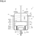
- Fig. 2 is a partial cross-sectional view of the reinforcing-fiber recovery reactor shown in Fig. 1 .
- a reinforcing-fiber recovery reactor 1 shown in Fig. 1 is used to recover reinforcing fibers from a fiber-reinforced resin material by a solvent method.
- the fiber-reinforced resin material is a resin material reinforced by embedded reinforcing fibers such as carbon fibers. Details of the fiber-reinforced resin material will be described later.
- a reinforcing-fiber recovery reactor 1 includes a reaction vessel 10, a lid 20, a fixing mechanism 30 and a support base 40. In the following description, each component of the reinforcing-fiber recovery reactor 1 will be specifically described in order.
- the reaction vessel 10 is capable of accommodating a fiber-reinforced resin material and a solvent. As shown in Fig. 2 , the reaction vessel 10 includes a reaction vessel body 11, a temperature control jacket 13, a drain port 15, a valve 17 and a flange 19.
- the reaction vessel body 11 is a bottomed cylindrical vessel having a bottom 113 at the bottom and an opening 115 at the top.
- the reaction vessel body 11 includes an accommodation space 111 capable of accommodating a fiber-reinforced resin material and a solvent. Materials required for reaction of a fiber-reinforced resin material, a solvent, and the like are introduced into the accommodation space 111 of the reaction vessel body 11 through the opening 115.
- the temperature control jacket 13 is disposed covering the outer peripheral side surface of the reaction vessel body 11.
- the temperature control jacket 13 is capable of controlling the temperature of the contents by heating and/or cooling the contents accommodated in the reaction vessel body 11.
- a heating medium such as water, is passed through the temperature control jacket 13 to exchange heat to thereby control the temperature of the contents.
- the temperature control jacket 13 may be a heating means such as an electric heater.
- the drain port 15 is provided in the bottom 113 of the reaction vessel body 11, and liquid such as a treatment solution can be discharged from the accommodation space 111 of the reaction vessel body 11 through the drain port 15. Further, a valve 17 is provided in the drain port 15, and opening and closing of the drain port 15 can be controlled by operating the valve 17.
- the flange 19 is a disk-shaped member that protrudes from the outer peripheral edge of the reaction vessel body 11 near the opening 115.
- the flange 19 is configured to abut a flange 27 of the lid 20, which will be described later, during reaction to prevent, together with the flange 27, leakage of the contents of the reaction vessel body 11. Further, by fixing the flange 19 and the flange 27 to each other, the lid 20 can be fixed to the reaction vessel body 11.
- the lid 20 is a detachable lid capable of opening and closing the reaction vessel 10, and can close the reaction vessel 10 by being disposed covering the opening 115.
- the lid 20 includes a lid body 21, an injection port 23, an exhaust port 25 and a flange 27.
- the lid body 21 is a main part of the lid 20, and has a shape of an inverted bowl.
- a through hole is formed in a center part of the lid body 21, and a control member 33 of the fixing mechanism 30, which will be described later, extends through the through hole.
- the injection port 23 and the exhaust port 25 are attached to the lid body 21.
- the injection port 23 is a pipe for injecting a treatment solution such as a solvent.
- the exhaust port 25 is a pipe for removing an excess gas, such as vapor, generated in use of the reaction vessel 10.
- the injection port 23 and the exhaust port 25 are provided on the top of the lid body 21.
- the present invention is not limited to the illustrated embodiment, and the injection port 23 and the exhaust port 25 can be attached to any position of the lid body 21 or any position of the reaction vessel 10.
- a plurality of injection ports 23 and exhaust ports 25 may be provided according to the application.
- the flange 27 is a disk-shaped member that protrudes from the outer peripheral edge of the lid body 21 on the side of the opening 115 of the reaction vessel 10.
- the flange 27 is configured to abut the flange 19 of the reaction vessel 10 during reaction to prevent, together with the flange 19, leakage of the contents of the reaction vessel body 11.
- the fixing mechanism 30 fixes the fiber-reinforced resin material by pressing it in use of the reinforcing-fiber recovery reactor 1.
- the fixing mechanism 30 includes a pressing member 31, a control member 33, a support member 35, an elastic member 37 and a regulating member 39.
- the pressing member 31 is disposed in the accommodation space 111 of the reaction vessel 10 in use of the reinforcing-fiber recovery reactor 1.
- the pressing member 31 has a plate shape having a pressing surface 311 for pressing the fiber-reinforced resin material.
- the pressing member 31 is disposed with the pressing surface 311 being horizontal and substantially parallel to a support surface 351 of the support member 35.
- the position of the pressing member 31 having the above configuration is controlled by the control member 33 so that the pressing surface 311 can be pressed against the fiber-reinforced resin material.
- the area of the pressing surface 311 of the pressing member 31 is not particularly limited, but may be, for example, 10% or more and 90% or less, preferably 30% or more and 50% or less, of the cross-sectional area of the accommodation space 111 parallel to the pressing surface 311. Accordingly, while the fiber-reinforced resin material is fixed by the pressing member 31, a treatment solution can easily flow in the accommodation space 111, which facilitates permeation of the treatment solution into the fiber-reinforced resin material.
- the control member 33 is a rod-shaped member with one end connected to the pressing member 31.
- the other end of the control member 33 penetrates the lid body 21 and is connected to a driving device (not shown).
- a driving device not shown.
- the control member 33 moves in a direction perpendicular to the pressing surface 311 (i.e., vertically in the drawing)
- the pressing member 31 can move in the direction perpendicular to the pressing surface 311.
- the support member 35 is disposed under the control member 33 in the accommodation space 111.
- the support member 35 has a plate shape and is disposed with the support surface 351 on one side facing the pressing surface 311.
- the support member 35 supports the fiber-reinforced resin material between the support surface 351 and the pressing member 31.
- the fiber-reinforced resin material can be fixed between the pressing member 31 and the support member 35.
- the area of the support surface 351 of the support member 35 is not particularly limited, but may be, for example, 10% or more and 90% or less, preferably 30% or more and 50% or less, of the cross-sectional area of the accommodation space 111 parallel to the support surface 351. Accordingly, while the fiber-reinforced resin material is fixed by the support member 35, a treatment solution can easily flow in the accommodation space 111, which facilitates permeation of the treatment solution into the fiber-reinforced resin material.
- the elastic member 37 is disposed between the support member 35 and the bottom 113 of the reaction vessel body 11 to support the support member 35.
- the elastic member 37 is a compression coil spring. Due to such an elastic member 37 supporting the support member 35, the support member 35 can move downward according to the pressing force from the pressing member 31. This prevents excessive pressure from being applied to the fiber-reinforced resin material, and suppresses damage to the reinforcing fibers in the fiber-reinforced resin material. Further, due to the elastic member 37 being provided, the support member 35 can reciprocate corresponding to reciprocation of the pressing member 31. As the pressing member 31 and the support member 35 reciprocate, the treatment solution in the accommodation space 111 is agitated.
- the regulating member 39 includes a regulating plate 391 and a connecting member that connects the regulating plate 391 to the bottom 113 of the reaction vessel body 11.
- the regulating plate 391 is fixed substantially parallel to the support member 35 between the support member 35 and the bottom 113 of the reaction vessel body 11.
- the support member 35 moves downward, it abuts the regulating plate 391 of the regulating member 39, whereby the downward movement of the support member 35 is regulated. That is, the regulating member 39 controls the position to which the support member 35 can move downward. Since the fixing mechanism 30 has the regulating member 39, it is possible to compress the fiber-reinforced resin material between the pressing member 31 and the support member 35 by moving the pressing member 31 downward.
- the support base 40 shown in Fig. 1 is a base supporting the reaction vessel 10.
- the support base 40 includes a support base body 41 and a rotary shaft 43.
- the support base body 41 has pillar-shaped legs and is placed on the ground.
- the rotary shaft 43 is rotatably connected to the upper part of the support base body 41 and the reaction vessel 10. This enables tilting of the reaction vessel 10. As a result, the opening 115 of the reaction vessel 10 can be tilted downward, which facilitates introduction of the fiber-reinforced resin material and removal of the reinforcing fibers after reaction.
- a reaction can be performed while the fixing mechanism 30 presses and fixes the fiber-reinforced resin material. Accordingly, when the fiber-reinforced resin material is subjected to treatment with the treatment solution containing the solvent, the shape of the reinforcing fibers in the fiber-reinforced resin material becomes less likely to be deformed. In particular, even after the resin component in the fiber-reinforced resin material is dissolved and the reinforcing fibers are exposed during treatment, the reinforcing fibers are less likely to be entangled since the reinforcing fibers are fixed by the fixing mechanism 30.
- the treatment solution can uniformly permeate through the reinforcing fibers in the fiber-reinforced resin material, and thus the dissolution reaction of the resin component can uniformly proceed.
- a reaction can be performed while the fixing mechanism 30 presses and fixes the fiber-reinforced resin material. Therefore, a variety of fiber-reinforced resin materials can be subjected to treatment regardless of the size and shape. For example, finely cut fiber-reinforced resin materials or large prepreg sheets can be subjected to treatment to recover recycled reinforcing fibers.
- the reinforcing-fiber recovery reactor 1 can also be used for washing and deliquoring the recovered recycled reinforcing fibers. Therefore, a plurality of steps for recovering recycled reinforcing fibers can be performed using the reinforcing-fiber recovery reactor 1 without changing the device.
- a treatment solution can be agitated as the pressing member 31 reciprocates.
- the support member 35 can reciprocate as the pressing member 31 reciprocates, agitation can be performed while the fiber-reinforced resin material is fixed.
- the method of producing recycled reinforcing fibers according to the present invention includes a dissolving step of subjecting a fiber-reinforced resin material containing reinforcing fibers and a resin component to treatment with a treatment solution containing a solvent to dissolve at least part of the resin component in the treatment solution, wherein the fiber-reinforced resin material is subjected to treatment with the treatment solution in the dissolving step while being pressed and fixed.
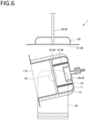
- Figs. 3 to 6 are partial cross-sectional views illustrating an example of operation of the reinforcing-fiber recovery reactor in the method of producing recycled reinforcing fibers according to the present embodiment. In the following description, each step in the method of producing recycled reinforcing fibers according to the present embodiment will be described.
- a fiber-reinforced resin material 100 used in the dissolving step is prepared.
- the fiber-reinforced resin material is a resin material reinforced by embedded reinforcing fibers.
- the fiber-reinforced resin material 100 include, but are not limited to, carbon fiber reinforced plastics (CFRP), glass fiber reinforced plastics (GFRP), glass-mat reinforced thermoplastics (GMT), aramid-fiber-reinforced plastics (AFRP), Kevlar fiber reinforced plastics (KFRP), Dyneema fiber-reinforced plastics (DFRP), basalt fiber reinforced plastics, boron fiber reinforced plastics, and prepregs thereof.
- CFRP carbon fiber reinforced plastics
- GFRP glass fiber reinforced plastics
- GTT glass-mat reinforced thermoplastics
- AFRP aramid-fiber-reinforced plastics
- KFRP Kevlar fiber reinforced plastics
- DFRP Dyneema fiber-reinforced plastics
- basalt fiber reinforced plastics boro
- the reinforcing fibers in the fiber-reinforced resin material 100 may be in the form of fiber bundles (tows) in which a plurality of reinforcing fibers are aligned in one direction, or in the form of a woven fabric or a non-woven fabric in which fiber bundles of reinforcing fibers are used as warp and weft, or the reinforcing fibers may be arranged at random positions and orientations.
- the method according to the present embodiment is suitable for recovering reinforcing fibers from the fiber-reinforced resin material containing reinforcing fibers in the form of a fiber bundle or a woven fabric.
- the reinforcing fibers may be in the form of chips, and examples thereof include chopped fibers obtained by cutting fiber bundles, chips of a woven fabric, and the like.
- the resin component contained in the fiber-reinforced resin material 100 is not particularly limited, and may be, for example, either a thermosetting resin or a thermoplastic resin.
- the thermosetting resin may be uncured or may be a cured product.
- thermosetting resin examples include, but are not limited to, epoxy resins, unsaturated polyester resins, vinyl ester resins, phenol resins, cyanate resins, polyimide resins, melamine resins, urethane resins, polycarbonate resins, polyacetal resins, and the like, and these can be used singly or in combination of two or more for the resin component.
- thermoplastic resin examples include, but are not limited to, polyamides, polyolefins, polyesters, polycarbonates, acrylic resins, acrylonitrile-butadiene-styrene copolymers, polyether ketones, polyphenylene sulfides, and the like, and these can be used singly or in combination of two or more for the resin component.
- the fiber-reinforced resin material 100 may have a sheet shape, or may be in the form of cut chips.
- the method according to the present embodiment can be suitably used for the sheet-shaped fiber-reinforced resin material 100, from which it has been difficult to recover reinforcing fibers.
- the size of the fiber-reinforced resin material 100 is not particularly limited as long as it can be accommodated in the accommodation space 111 of the reaction vessel 10.
- the length of each piece of the fiber-reinforced resin material 100 may be, for example, 100 mm or more, and preferably 500 mm or more and 3,000 mm or less. More specifically, as the fiber-reinforced resin material 100, for example, a fiber-reinforced resin material sheet having a laminate thickness of approximately 300 mm and a size of 1,000 mm ⁇ 500 mm can be used.
- the prepared fiber-reinforced resin material 100 is subjected to treatment with a treatment solution 200 containing a solvent so that at least part of a resin component is dissolved in the treatment solution 200.
- the fiber-reinforced resin material 100 and the treatment solution 200 are introduced into the accommodation space 111 of the reaction vessel 10 of the reinforcing-fiber recovery reactor 1 as shown in Figs. 3 and 4 , and subjected to treatment in the reaction vessel 10.
- the treatment solution 200 will be described first, and then a specific procedure will be described.
- the treatment solution 200 in this step contains at least a solvent, and at least part of the resin component in the fiber-reinforced resin material 100 is dissolved.
- the term "resin component is dissolved” as used herein means not only that the resin component itself directly dissolves in the treatment solution 200, but also that the resin component decomposes to produce a reaction product, and the reaction product dissolves in the treatment solution 200.
- the solvent is a main component of the treatment solution 200.
- the solvent is not particularly limited as long as it can dissolve the resin component of the fiber-reinforced resin material 100 or a reaction product in this step, and may be, for example, water and/or various organic solvents.
- organic solvents examples include, but are not limited to, alcohol-based solvents, ether-based solvents, ester-based solvents, ketone-based solvents, amide-based solvents, aromatic hydrocarbons, halogenated aromatic hydrocarbons, halogenated aliphatic hydrocarbons, and the like, and these can be used singly or in combination of two or more.
- alcohol-based solvents examples include aliphatic alcohol-based solvents, aromatic alcohol-based solvents, glycol-based solvents and other polyhydric alcohols such as glycerin.
- aliphatic alcohol-based solvents include acyclic aliphatic alcohols such as 1-butanol, 2-butanol, 2-methyl-1-propanol, 2-methyl-2-propanol, 1-pentanol, 2-pentanol, 3-pentanol, 2-methyl-1-butanol, 2-methyl-2-butanol, 3-methyl-1-butanol, 3-methyl-2-butanol, 2,2-dimethyl-1-propanol, 1-hexanol, 2-hexanol, 3-hexanol, 2-ethylhexanol, 2-methyl-1-pentanol, 4-methyl-2-pentanol, 2-ethyl-1-butanol, 1-heptanol, 2-heptanol, 3-heptanol, dodecanol, methanol and ethanol; and alicyclic alcohols such as cyclohexanol, 1-methylcyclohexanol, 2-methylcyclohexan
- aromatic alcohol-based solvents examples include phenol, cresol, benzyl alcohol and phenoxyethanol.
- glycol-based solvents examples include ethylene glycol, ethylene glycol monomethyl ether, ethylene glycol monoethyl ether, ethylene glycol monopropyl ether, ethylene glycol monobutyl ether, diethylene glycol, diethylene glycol monomethyl ether, diethylene glycol monoethyl ether, diethylene glycol monopropyl ether, diethylene glycol monobutyl ether, triethylene glycol, triethylene glycol monomethyl ether, triethylene glycol monoethyl ether, tetra ethylene glycol, polyethylene glycol (molecular weight 200 to 400), 1,2-propanediol, 1,3-propanediol, 1,2-butanediol, 1,3-butanediol, 1,4-butanediol, 2,3-butanediol, 1,5-pentanediol and dipropylene glycol.
- ether-based solvents examples include aliphatic ethers such as dimethyl ether, diethyl ether, ethyl methyl ether, dipropyl ether, diisopropyl ether, dibutyl ether and dihexyl ether; cyclic ethers such as 1,3-dioxolane, 1,4-dioxane, tetrahydrofuran and furan; and aromaticcontaining ethers such as anisole, phenetole, diphenyl ether and benzofuran.
- aliphatic ethers such as dimethyl ether, diethyl ether, ethyl methyl ether, dipropyl ether, diisopropyl ether, dibutyl ether and dihexyl ether
- cyclic ethers such as 1,3-dioxolane, 1,4-dioxane, tetrahydrofuran and furan
- aromaticcontaining ethers such as anisole
- ester-based solvents examples include methyl formate, ethyl formate, propyl formate, butyl formate, isobutyl formate, pentyl formate, methyl acetate, ethyl acetate, propyl acetate, isopropyl acetate, butyl acetate, isobutyl acetate, pentyl acetate, isopentyl acetate, 3-methoxybutyl acetate, 2-ethylbutyl acetate, 2-ethylhexyl acetate, cyclohexyl acetate, benzyl acetate, methyl propionate, ethyl propionate, butyl propionate, isopentyl propionate, methyl lactate, ethyl lactate, butyl lactate, methyl butyrate, ethyl butyrate, butyl butyrate, isopentyl butyrate, isobutyl
- ketone-based solvents examples include acetone, methyl ethyl ketone, 2-pentanone, 3-pentanone, 2-hexanone, methyl isobutyl ketone, 2-heptanone, 4-heptanone, diisobutyl ketone, cyclohexanone, methylcyclohexanone, phorone, isophorone, acetylacetone, acetophenone, diethylketone and diacetone alcohol.
- amide-based solvents examples include formamide, N-methylformamide, N,N-dimethylformamide, N,N-diethylformamide, acetamide, N-methylacetamide, N,N-dimethylacetamide, 2-pyrrolidone, N-methyl-2-pyrrolidone, caprolactam and carbamic acid ester.
- aromatic hydrocarbons examples include benzene, toluene and xylene.
- halogenated aromatic hydrocarbons examples include orthochlorophenol and orthodichlorobenzene.
- halogenated aliphatic hydrocarbons examples include chloroform and methylene chloride.
- the solvent content in the treatment solution 200 is not particularly limited, but may be, for example, 0.01 mass% or more and 100 mass% or less, preferably 40 mass% or more and 60 mass% or less, and more preferably 80 mass% or more and 100 mass% or less.
- the treatment solution 200 may contain a catalyst.
- the catalyst is not particularly limited as long as it catalyzes the dissolution of the resin component in the fiber-reinforced resin material 100, and examples thereof include acidic substances and basic substances. These substances can improve the solubility of the resin component in a solvent, for example, by adding a hydrogen ion, a hydroxide ion, or the like to a functional group of the resin component, or by decomposing the resin component.
- the solvent contains a protic solvent, especially water, the catalytic action of acidic substances and basic substances is further improved.
- Examples of the acidic substance include inorganic acids, organic acids, salts thereof, and mixtures thereof.
- Examples of the inorganic acids include nitric acid, sulfuric acid, hydrochloric acid and phosphoric acid, and these can be used singly or in combination of two or more.
- Examples of the phosphate include orthophosphate, metaphosphate, hypophosphate, phosphite, hypophosphite, pyrophosphate, trimetaphosphate, tetrametaphosphate and pyrophosphite.
- Examples of the organic acids include formic acid, acetic acid, citric acid, succinic acid and oxalic acid.
- salts of inorganic acids or organic acids include salts of alkali metals (for example, sodium, potassium, cesium, rubidium, or the like) and/or alkaline earth metals (for example, beryllium, magnesium, calcium, strontium, barium, or the like) of the inorganic acids or organic acids described above.
- alkali metals for example, sodium, potassium, cesium, rubidium, or the like
- alkaline earth metals for example, beryllium, magnesium, calcium, strontium, barium, or the like
- inorganic acids in particular, nitric acid, sulfuric acid, hydrochloric acid and phosphoric acid are preferred since they are easily available and tend to contribute to promotion of the dissolution of the resin component.
- the content of the acidic substance can be appropriately selected depending on the type of the acidic substance used, the type of the solvent in the treatment solution 200, and the resin component in the target fiber-reinforced resin material 100.
- the content of the acidic substance in the treatment solution 200 may be, for example, 0.01 mass% or more and 100 mass% or less, and in particular 10 mass% or more and 50 mass% or less.
- Examples of the basic substances include inorganic basic substances such as hydroxides, carbonates, hydrogen carbonates, sulfates, sulfites and nitrates of lithium, alkali metals and alkaline earth metals; and amine compounds such as dimethylamine and diethylamine, and these can be used singly or in combination of two or more.
- Examples of the alkali metals include sodium, potassium, cesium and rubidium.
- Examples of the alkaline earth metals include beryllium, magnesium, calcium, strontium and barium.
- the basic substance preferably contains one or more selected from the group consisting of sodium hydroxide, potassium hydroxide, sodium hydrogen carbonate, sodium carbonate, potassium hydrogen carbonate and potassium carbonate.
- the content of the basic substance can be appropriately selected depending on the type of the basic substance used, the type of the solvent in the treatment solution 200, and the resin component in the target fiber-reinforced resin material 100.
- the content of the basic substance in the treatment solution 200 may be, for example, 0.01 mass% or more and 100 mass% or less, and in particular 10 mass% or more and 50 mass% or less.
- the fiber-reinforced resin material 100 is introduced into the accommodation space 111 of the reaction vessel 10.
- the fiber-reinforced resin material 100 is disposed between the pressing member 31 and the support member 35 of the fixing mechanism 30.
- the treatment solution 200 is injected into the accommodation space 111 through the injection port 23.
- the treatment solution 200 may be collectively injected into the accommodation space 111, or the components constituting the treatment solution 200 may be separately injected into the accommodation space 111.
- the fixing mechanism 30 may not necessarily fix the fiber-reinforced resin material 100.
- the fiber-reinforced resin material 100 is subjected to treatment with the treatment solution.
- treatment with the treatment solution 200 is performed while the pressing member 31 of the fixing mechanism 30 presses and fixes the fiber-reinforced resin material 100.
- the pressure of the pressing surface 311 when the pressing member 31 presses the fiber-reinforced resin material 100 is not particularly limited, but may be, for example, 8.5 ⁇ 10 -5 Pa or more and 8.5 Pa or less, and preferably 8.5 ⁇ 10 -4 Pa or more and 8.5 -1 Pa or less.
- the pressing member 31 is preferably reciprocated vertically to agitate the treatment solution 200.
- the support member 35 supported by the elastic member 37 reciprocates in accordance with the reciprocation of the pressing member 31. Therefore, the fiber-reinforced resin material 100 is fixed between the pressing member 31 and the support member 35 of the fixing mechanism 30 even when the pressing member 31 is reciprocated.
- the treatment solution 200 can be agitated while the fiber-reinforced resin material 100 is fixed.
- a general agitating blade or the like is used to agitate a treatment solution, but in this case, the reinforcing fibers exposed from the fiber-reinforced resin material may be damaged by the agitating blade, or the reinforcing fibers may be entangled with the agitating blade. Therefore, it has been difficult to recover the reinforcing fibers while maintaining the shape and orientation of the reinforcing fibers.
- agitation is performed while the fixing mechanism 30 fixes the fiber-reinforced resin material 100 to thereby suppress the above problem. Accordingly, it is possible to recover the reinforcing fibers while maintaining the shape and orientation of the reinforcing fibers.
- the moving distance (one-way distance) of the pressing member 31 that reciprocates when agitating the treatment solution 200 using the fixing mechanism 30 is not particularly limited, but may be, for example, 5 mm or more and 1,000 mm or less, and preferably 50 mm or more and 300 mm or less.
- the temperature of the treatment solution 200 during treatment is not particularly limited and varies depending on the type of the treatment solution 200, and may be, for example, 30°C or more and 300°C or less, and preferably 50°C or more and 100°C or less.
- the temperature of the treatment solution 200 is adjusted by operating the temperature control jacket 13.
- the treatment time with the treatment solution 200 is not particularly limited, and may be 1 minute or more and 1,440 minutes or less, and preferably 10 minutes or more and 60 minutes or less after the target temperature is reached.
- the treatment with the treatment solution 200 may be performed under normal pressure, reduced pressure, or increased pressure.
- the pressure may be, for example, 0.11 MPa or more and 7.0 MPa or less, and in particular 0.11 MPa or more and 2.0 MPa or less.
- the treatment with the treatment solution 200 is preferably performed under normal pressure.
- valve 17 is operated to open the drain port 15, as shown in Fig. 5 , so that the treatment solution 200 is discharged from the drain port 15.
- the pressing member 31 preferably presses the fiber-reinforced resin material 100 to compress the fiber-reinforced resin material 100. This enables efficient deliquoring. Specifically, when the pressing member 31 moves downward, the support member 35 moves accordingly to a position where it abuts the regulating member 39. As the pressing member 31 further presses the fiber-reinforced resin material 100 with an appropriate pressure, deliquoring can be performed.
- washing is performed as necessary. Washing can be performed by exposing the fiber-reinforced resin material 100 to a cleaning solution. Specifically, washing can be performed by replacing the treatment solution 200 with a cleaning solution in the above dissolving step and deliquoring step. The temperature of the cleaning solution and the washing time during washing can be appropriately set.
- Washing can be performed while the fixing mechanism 30 fixes the fiber-reinforced resin material 100. Accordingly, it is possible to wash and recover the reinforcing fibers while maintaining the shape and orientation of the reinforcing fibers contained in the fiber-reinforced resin material 100.
- cleaning solution examples include water and various organic solvents described above as the solvent of the treatment solution 200, and these can be used singly or in combination of two or more.
- the cleaning solution may contain an acidic substance or a basic substance. These substances can be used to adjust the liquid properties so that a resin component remaining in the fiber-reinforced resin material 100 and a reaction product thereof can be removed.
- Each of the dissolving step, deliquoring step and washing step described above can be performed multiple times as necessary. For example, after the dissolving step and deliquoring step are repeated multiple times, the washing step may be performed. Alternatively, for example, after the dissolving step is performed multiple times, the deliquoring step may be performed, and then the washing step may be performed a required number of times. Alternatively, for example, the dissolving step, deliquoring step and washing step may be performed in this order a required number of times.
- the fiber-reinforced resin material 100 may be dried. Drying may be performed, for example, by circulating a gas in the accommodation space 111 of the reaction vessel 10 with an air supply means (not shown).
- the circulated gas is not particularly limited, but is preferably air or an inert gas such as nitrogen from the viewpoint of safety.
- the fiber-reinforced resin material 100 may be heated. This accelerates drying. Heating may be performed, for example, by using the temperature control jacket 13 or by introducing a heated gas into the reaction vessel 10.
- the temperature of the gas during heating may be, for example, 0°C or more and 400°C or less, and preferably 80°C or more and 110°C or less.
- Heating may be performed while the fixing mechanism 30 fixes the fiber-reinforced resin material 100. Accordingly, it is possible to dry the reinforcing fibers while maintaining the shape and orientation of the reinforcing fibers contained in the fiber-reinforced resin material 100.
- the reinforcing fibers are recovered from the fiber-reinforced resin material 100 to obtain recycled reinforcing fibers.
- the opening 115 of the reaction vessel 10 is tilted downward around the rotary shaft 43 of the support base 40 so that the recycled reinforcing fibers can be taken out easily.
- recycled reinforcing fibers can be obtained.
- the resin component in the fiber-reinforced resin material 100 is dissolved in the treatment solution 200 containing a solvent while the fixing mechanism 30 presses and fixes the fiber-reinforced resin material 100. Accordingly, when the fiber-reinforced resin material 100 is subjected to treatment with the treatment solution 200 containing the solvent, the shape of the reinforcing fibers in the fiber-reinforced resin material 100 becomes less likely to be deformed. In particular, even after the resin component in the fiber-reinforced resin material 100 is dissolved and the reinforcing fibers are exposed during treatment, the reinforcing fibers are less likely to be entangled since they are fixed.
- the treatment solution can uniformly permeate through the reinforcing fibers in the fiber-reinforced resin material 100, and thus the dissolution reaction of the resin component can uniformly proceed.
- a reaction can be performed while the fixing mechanism 30 presses and fixes the fiber-reinforced resin material. Therefore, a variety of fiber-reinforced resin materials 100 can be subjected to treatment regardless of the size and shape. For example, finely cut fiber-reinforced resin materials or large prepreg sheets can be subjected to treatment to recover recycled reinforcing fibers.
- the support member 35 supported by the elastic member 37 is provided, but the present invention is not limited thereto, and the support member 35 may be omitted, for example, as in a reinforcing-fiber recovery reactor 1A shown in Fig. 7 .
- the bottom 113 of the reaction vessel body 11 functions as a support member, and the pressing member 31, the control member 33 and the bottom 113 constitute a fixing mechanism 30A.
- the fixing mechanism 30 is configured such that the pressing member 31 and the support member 35 press and fix the fiber-reinforced resin material 100 in the vertical direction, but the present invention is not limited thereto, and the fixing mechanism may press and fix the fiber-reinforced resin material in any direction.
- the pressing member and the support member may be disposed to press and fix the fiber-reinforced resin material in the horizontal direction.
- the pressing member 31 and the support member 35 have a plate shape, but the present invention is not limited thereto.
- holes may be formed in the pressing member and the support member. This reduces the fluid resistance during agitation.
- the pressing member and the support member may be mesh sheets.
- agitation of the treatment solution 200 is performed by vertically reciprocating the pressing member 31 and the support member 35
- the reaction vessel may be provided with an agitating device at a position that does not come into contact with the fiber-reinforced resin material.
- agitation may be performed by moving the reaction vessel while fixing the position of the fixing mechanism.
- the mode of motion of the reaction vessel is not particularly limited, and may be, for example, a reciprocating motion in the vertical direction and/or horizontal direction or a rotary motion.
- the elastic member 37 is described as a compression coil spring, but the present invention is not limited thereto, and the elastic member may be formed of any elastic member.
- examples of such an elastic member include a leaf spring such as a laminated leaf spring and a thin leaf spring, a torsion spring, a volute spring, and a polymer elastic body such as rubber or elastomer.
- reaction vessel 10 and the reaction vessel body 11 are described as having a cylindrical shape, but the present invention is not limited thereto.
- the shape of the reaction vessel body 11 may be changed so that the accommodation space has a substantially rectangular parallelepipied shape.
Landscapes
- Engineering & Computer Science (AREA)
- Environmental & Geological Engineering (AREA)
- Mechanical Engineering (AREA)
- Health & Medical Sciences (AREA)
- Chemical & Material Sciences (AREA)
- Chemical Kinetics & Catalysis (AREA)
- General Chemical & Material Sciences (AREA)
- General Health & Medical Sciences (AREA)
- Toxicology (AREA)
- Separation, Recovery Or Treatment Of Waste Materials Containing Plastics (AREA)
Abstract
Description
- The present application claims the benefit of priority from
Japanese Patent Application No. 2020-200195, filed December 2, 2020 - The present invention relates to a reinforcing-fiber recovery reactor and a method of producing recycled reinforcing fibers.
- Fiber reinforced plastics (FRP) using fibers such as glass fibers as a reinforcing material are lightweight, high strength and high elasticity materials, and are widely used for members of small ships, automobiles, railway vehicles, and the like. In addition, carbon fiber reinforced plastics (CFRP) using carbon fibers as a reinforcing material have been developed for further reducing weight, increasing strength and increasing elasticity, and are used for members of aircraft, automobiles, and the like.
- In recent years, the amount of fiber reinforced plastic waste has tended to increase, and the development of recycling technology is being studied. Methods for recovering reinforcing fibers from fiber reinforced plastics mainly include a pyrolysis method, in which a resin component is thermally decomposed and removed by heat treatment to thereby recover reinforcing fibers, and a solvent method, in which a resin component is dissolved in a solvent and removed to thereby recover reinforcing fibers. Among these methods, the solvent method is advantageous from the viewpoint of resource recycling since the resin component can be easily recovered.
- An example of the solvent method is proposed in PTL 1. PTL 1 discloses a method including the steps of: obtaining cut pieces by cutting a block of composite material containing an inorganic material and an organic material; and obtaining crushed pieces by crushing the cut pieces. In PTL 1, as a method of separating the inorganic material and the organic material of the crushed pieces, a method of decomposing the organic material using a treatment solution capable of decomposing the organic material contained in the crushed pieces and recovering the inorganic material is proposed.
- [PTL1]
JP 2020-011482 A - However, in the solvent method, it is necessary to agitate the mixture of the solvent and the fiber-reinforced resin material in order to efficiently dissolve the resin component contained in the fiber-reinforced resin material. When the mixture is agitated, it is difficult to maintain the shape and orientation of fiber bundles of the reinforcing fibers present in the fiber-reinforced resin material. If the shape and orientation of fiber bundles of the reinforcing fibers cannot be maintained, the fiber directions of the recovered reinforcing fibers are not aligned, and the applications of the recovered reinforcing fibers are limited.
- Therefore, an object of the present invention is to provide a reinforcing-fiber recovery reactor and a method of producing recycled reinforcing fibers capable of maintaining the shape and orientation of reinforcing fiber bundles when the reinforcing fibers are separated from a fiber-reinforced resin material by a solvent method.
- The inventors of the present invention have studied how to maintain the shape and orientation of the reinforcing fibers in the fiber-reinforced resin material when using the solvent method, and found that the shape and orientation of the reinforcing fibers are maintained when the fiber-reinforced resin material itself can be fixed at a fixed position. The inventors of the present invention conducted further studies based on the above findings, and arrived at the present invention.
- The gist of the present invention is as follows.
- (1) A reinforcing-fiber recovery reactor used for recovering reinforcing fibers from a fiber-reinforced resin material by a solvent method, the reactor including:
- a reaction vessel that can accommodate the fiber-reinforced resin material and a solvent; and
- a fixing mechanism comprising a pressing member capable of pressing the fiber-reinforced resin material, the fixing mechanism being capable of fixing the accommodated fiber-reinforced resin material by pressing the fiber-reinforced resin material with the pressing member.
- (2) The reinforcing-fiber recovery reactor according to (1), wherein the pressing member has a plate shape.
- (3) The reinforcing-fiber recovery reactor according to (1) or (2), wherein the pressing member has a pressing surface configured to be pressed against the fiber-reinforced resin material, the pressing member being reciprocable in a direction perpendicular to the pressing surface.
- (4) The reinforcing-fiber recovery reactor according to any one of (1) to (3), wherein the fixing mechanism comprises a support member configured to support the fiber-reinforced resin material between the pressing member and the support member.
- (5) The reinforcing-fiber recovery reactor according to (4), wherein the support member has a plate shape.
- (6) The reinforcing-fiber recovery reactor according to (4) or (5), wherein the support member is reciprocable toward and away from the pressing member.
- (7) The reinforcing-fiber recovery reactor according to any one of (4) to (6), further including an elastic member that supports the support member.
- (8) The reinforcing-fiber recovery reactor according to (7), wherein the elastic member is a compression coil spring.
- (9) The reinforcing-fiber recovery reactor according to any one of (4) to (8), further including a regulating member that regulates movement of the support member.
- (10) The reinforcing-fiber recovery reactor according to any one of (1) to (9), wherein the reaction vessel has an opening for introducing the fiber-reinforced resin material, and the reaction vessel is configured to be tiltable to tilt the opening downward.
- (11) The reinforcing-fiber recovery reactor according to any one of (1) to (10), wherein the reinforcing fibers comprises carbon fibers.
- (12) A method of producing recycled reinforcing fibers, the method including
- a step of subjecting a fiber-reinforced resin material comprising reinforcing fibers and a resin component to treatment with a treatment solution comprising a solvent using the reinforcing-fiber recovery reactor according to any one of (1) to (11) to dissolve at least part of the resin component in the treatment solution, wherein
- the fiber-reinforced resin material is subjected to treatment with the treatment solution in the step while being fixed by the fixing mechanism.
- (13) A method of producing recycled reinforcing fibers, the method including
- a step of subjecting a fiber-reinforced resin material comprising reinforcing fibers and a resin component to treatment with a treatment solution comprising a solvent to dissolve at least part of the resin component in the treatment solution, wherein
- the fiber-reinforced resin material is subjected to treatment with the treatment solution in the step while being pressed and fixed.
- (14) The method of producing recycled reinforcing fibers according to (12) or (13), wherein the solvent is agitated in the step while the fiber-reinforced resin material is fixed.
- According to the above configuration, it is possible to provide a reinforcing-fiber recovery reactor and a method of producing recycled reinforcing fibers capable of maintaining the shape and orientation of reinforcing fiber bundles when the reinforcing fibers are separated from a fiber-reinforced resin material by a solvent method.
-
-
Fig. 1 is a perspective view schematically illustrating a reinforcing-fiber recovery reactor according to an embodiment of the present invention. -
Fig. 2 is a partial cross-sectional view of the reinforcing-fiber recovery reactor shown inFig. 1 . -
Fig. 3 is a partial cross-sectional view illustrating operation of the reinforcing-fiber recovery reactor shown inFig. 1 . -
Fig. 4 is a partial cross-sectional view illustrating operation of the reinforcing-fiber recovery reactor shown inFig. 1 . -
Fig. 5 is a partial cross-sectional view illustrating operation of the reinforcing-fiber recovery reactor shown inFig. 1 . -
Fig. 6 is a partial cross-sectional view illustrating operation of the reinforcing-fiber recovery reactor shown inFig. 1 . -
Fig. 7 is a perspective view schematically illustrating a reinforcing-fiber recovery reactor according to another embodiment of the present invention. - With reference to the drawings, preferred embodiments of the present invention will be described in detail. In the drawings, components that do not need to be described are omitted for ease of illustration. Further, the dimensions of each component in the drawings are appropriately enlarged or reduced for ease of illustration, and do not indicate any actual scale of each component.
-
Fig. 1 is a perspective view schematically illustrating a reinforcing-fiber recovery reactor according to an embodiment of the present invention, andFig. 2 is a partial cross-sectional view of the reinforcing-fiber recovery reactor shown inFig. 1 . - A reinforcing-fiber recovery reactor 1 shown in
Fig. 1 is used to recover reinforcing fibers from a fiber-reinforced resin material by a solvent method. The fiber-reinforced resin material is a resin material reinforced by embedded reinforcing fibers such as carbon fibers. Details of the fiber-reinforced resin material will be described later. - A reinforcing-fiber recovery reactor 1 includes a
reaction vessel 10, alid 20, afixing mechanism 30 and asupport base 40. In the following description, each component of the reinforcing-fiber recovery reactor 1 will be specifically described in order. - The
reaction vessel 10 is capable of accommodating a fiber-reinforced resin material and a solvent. As shown inFig. 2 , thereaction vessel 10 includes areaction vessel body 11, atemperature control jacket 13, adrain port 15, avalve 17 and aflange 19. - The
reaction vessel body 11 is a bottomed cylindrical vessel having a bottom 113 at the bottom and anopening 115 at the top. Thereaction vessel body 11 includes anaccommodation space 111 capable of accommodating a fiber-reinforced resin material and a solvent. Materials required for reaction of a fiber-reinforced resin material, a solvent, and the like are introduced into theaccommodation space 111 of thereaction vessel body 11 through theopening 115. - The
temperature control jacket 13 is disposed covering the outer peripheral side surface of thereaction vessel body 11. Thetemperature control jacket 13 is capable of controlling the temperature of the contents by heating and/or cooling the contents accommodated in thereaction vessel body 11. A heating medium, such as water, is passed through thetemperature control jacket 13 to exchange heat to thereby control the temperature of the contents. Alternatively, thetemperature control jacket 13 may be a heating means such as an electric heater. - The
drain port 15 is provided in thebottom 113 of thereaction vessel body 11, and liquid such as a treatment solution can be discharged from theaccommodation space 111 of thereaction vessel body 11 through thedrain port 15. Further, avalve 17 is provided in thedrain port 15, and opening and closing of thedrain port 15 can be controlled by operating thevalve 17. - The
flange 19 is a disk-shaped member that protrudes from the outer peripheral edge of thereaction vessel body 11 near theopening 115. Theflange 19 is configured to abut aflange 27 of thelid 20, which will be described later, during reaction to prevent, together with theflange 27, leakage of the contents of thereaction vessel body 11. Further, by fixing theflange 19 and theflange 27 to each other, thelid 20 can be fixed to thereaction vessel body 11. - The
lid 20 is a detachable lid capable of opening and closing thereaction vessel 10, and can close thereaction vessel 10 by being disposed covering theopening 115. Thelid 20 includes alid body 21, aninjection port 23, anexhaust port 25 and aflange 27. - The
lid body 21 is a main part of thelid 20, and has a shape of an inverted bowl. A through hole is formed in a center part of thelid body 21, and acontrol member 33 of thefixing mechanism 30, which will be described later, extends through the through hole. Theinjection port 23 and theexhaust port 25 are attached to thelid body 21. - The
injection port 23 is a pipe for injecting a treatment solution such as a solvent. Theexhaust port 25 is a pipe for removing an excess gas, such as vapor, generated in use of thereaction vessel 10. In the present embodiment, theinjection port 23 and theexhaust port 25 are provided on the top of thelid body 21. However, the present invention is not limited to the illustrated embodiment, and theinjection port 23 and theexhaust port 25 can be attached to any position of thelid body 21 or any position of thereaction vessel 10. Also, a plurality ofinjection ports 23 andexhaust ports 25 may be provided according to the application. - The
flange 27 is a disk-shaped member that protrudes from the outer peripheral edge of thelid body 21 on the side of theopening 115 of thereaction vessel 10. Theflange 27 is configured to abut theflange 19 of thereaction vessel 10 during reaction to prevent, together with theflange 19, leakage of the contents of thereaction vessel body 11. - The fixing
mechanism 30 fixes the fiber-reinforced resin material by pressing it in use of the reinforcing-fiber recovery reactor 1. The fixingmechanism 30 includes a pressingmember 31, acontrol member 33, asupport member 35, anelastic member 37 and a regulatingmember 39. - The pressing
member 31 is disposed in theaccommodation space 111 of thereaction vessel 10 in use of the reinforcing-fiber recovery reactor 1. The pressingmember 31 has a plate shape having apressing surface 311 for pressing the fiber-reinforced resin material. In the present embodiment, the pressingmember 31 is disposed with thepressing surface 311 being horizontal and substantially parallel to asupport surface 351 of thesupport member 35. The position of the pressingmember 31 having the above configuration is controlled by thecontrol member 33 so that thepressing surface 311 can be pressed against the fiber-reinforced resin material. - The area of the
pressing surface 311 of the pressingmember 31 is not particularly limited, but may be, for example, 10% or more and 90% or less, preferably 30% or more and 50% or less, of the cross-sectional area of theaccommodation space 111 parallel to thepressing surface 311. Accordingly, while the fiber-reinforced resin material is fixed by the pressingmember 31, a treatment solution can easily flow in theaccommodation space 111, which facilitates permeation of the treatment solution into the fiber-reinforced resin material. - The
control member 33 is a rod-shaped member with one end connected to the pressingmember 31. The other end of thecontrol member 33 penetrates thelid body 21 and is connected to a driving device (not shown). As thecontrol member 33 moves in a direction perpendicular to the pressing surface 311 (i.e., vertically in the drawing), the pressingmember 31 can move in the direction perpendicular to thepressing surface 311. - The
support member 35 is disposed under thecontrol member 33 in theaccommodation space 111. Thesupport member 35 has a plate shape and is disposed with thesupport surface 351 on one side facing thepressing surface 311. When the pressingmember 31 presses the fiber-reinforced resin material, thesupport member 35 supports the fiber-reinforced resin material between thesupport surface 351 and the pressingmember 31. Thus, while the fiber-reinforced resin material is pressed by the pressingmember 31, the fiber-reinforced resin material can be fixed between the pressingmember 31 and thesupport member 35. - The area of the
support surface 351 of thesupport member 35 is not particularly limited, but may be, for example, 10% or more and 90% or less, preferably 30% or more and 50% or less, of the cross-sectional area of theaccommodation space 111 parallel to thesupport surface 351. Accordingly, while the fiber-reinforced resin material is fixed by thesupport member 35, a treatment solution can easily flow in theaccommodation space 111, which facilitates permeation of the treatment solution into the fiber-reinforced resin material. - The
elastic member 37 is disposed between thesupport member 35 and thebottom 113 of thereaction vessel body 11 to support thesupport member 35. Theelastic member 37 is a compression coil spring. Due to such anelastic member 37 supporting thesupport member 35, thesupport member 35 can move downward according to the pressing force from the pressingmember 31. This prevents excessive pressure from being applied to the fiber-reinforced resin material, and suppresses damage to the reinforcing fibers in the fiber-reinforced resin material. Further, due to theelastic member 37 being provided, thesupport member 35 can reciprocate corresponding to reciprocation of the pressingmember 31. As the pressingmember 31 and thesupport member 35 reciprocate, the treatment solution in theaccommodation space 111 is agitated. - The regulating
member 39 includes a regulatingplate 391 and a connecting member that connects the regulatingplate 391 to thebottom 113 of thereaction vessel body 11. The regulatingplate 391 is fixed substantially parallel to thesupport member 35 between thesupport member 35 and thebottom 113 of thereaction vessel body 11. When thesupport member 35 moves downward, it abuts the regulatingplate 391 of the regulatingmember 39, whereby the downward movement of thesupport member 35 is regulated. That is, the regulatingmember 39 controls the position to which thesupport member 35 can move downward. Since thefixing mechanism 30 has the regulatingmember 39, it is possible to compress the fiber-reinforced resin material between the pressingmember 31 and thesupport member 35 by moving the pressingmember 31 downward. - The
support base 40 shown inFig. 1 is a base supporting thereaction vessel 10. Thesupport base 40 includes asupport base body 41 and arotary shaft 43. Thesupport base body 41 has pillar-shaped legs and is placed on the ground. Therotary shaft 43 is rotatably connected to the upper part of thesupport base body 41 and thereaction vessel 10. This enables tilting of thereaction vessel 10. As a result, theopening 115 of thereaction vessel 10 can be tilted downward, which facilitates introduction of the fiber-reinforced resin material and removal of the reinforcing fibers after reaction. - As described above, in the reinforcing-fiber recovery reactor 1 according to the present embodiment, a reaction can be performed while the
fixing mechanism 30 presses and fixes the fiber-reinforced resin material. Accordingly, when the fiber-reinforced resin material is subjected to treatment with the treatment solution containing the solvent, the shape of the reinforcing fibers in the fiber-reinforced resin material becomes less likely to be deformed. In particular, even after the resin component in the fiber-reinforced resin material is dissolved and the reinforcing fibers are exposed during treatment, the reinforcing fibers are less likely to be entangled since the reinforcing fibers are fixed by the fixingmechanism 30. As a result, it is possible to maintain the shape and fiber direction of the obtained recycled reinforcing fibers, and for example, maintain the fiber direction of the obtained recycled reinforcing fibers in one direction, which improves the physical properties, such as physical strength, of the fiber-reinforced resin material produced using the recycled reinforcing fibers. - In addition, since the reinforcing fibers are less likely to be entangled after the resin component in the fiber-reinforced resin material is dissolved and the reinforcing fiber bundles are exposed during treatment, the treatment solution can uniformly permeate through the reinforcing fibers in the fiber-reinforced resin material, and thus the dissolution reaction of the resin component can uniformly proceed.
- Furthermore, in the reinforcing-fiber recovery reactor 1 according to the present embodiment, a reaction can be performed while the
fixing mechanism 30 presses and fixes the fiber-reinforced resin material. Therefore, a variety of fiber-reinforced resin materials can be subjected to treatment regardless of the size and shape. For example, finely cut fiber-reinforced resin materials or large prepreg sheets can be subjected to treatment to recover recycled reinforcing fibers. - The reinforcing-fiber recovery reactor 1 according to the present embodiment can also be used for washing and deliquoring the recovered recycled reinforcing fibers. Therefore, a plurality of steps for recovering recycled reinforcing fibers can be performed using the reinforcing-fiber recovery reactor 1 without changing the device.
- Further, in the reinforcing-fiber recovery reactor 1 according to the present embodiment, in which the pressing
member 31 is configured to be reciprocable, a treatment solution can be agitated as the pressingmember 31 reciprocates. In the present embodiment, since thesupport member 35 can reciprocate as the pressingmember 31 reciprocates, agitation can be performed while the fiber-reinforced resin material is fixed. - Next, a method of producing recycled reinforcing fibers according to an embodiment of the present invention will be described. The method of producing recycled reinforcing fibers according to the present invention includes a dissolving step of subjecting a fiber-reinforced resin material containing reinforcing fibers and a resin component to treatment with a treatment solution containing a solvent to dissolve at least part of the resin component in the treatment solution, wherein the fiber-reinforced resin material is subjected to treatment with the treatment solution in the dissolving step while being pressed and fixed.
- The method of producing recycled reinforcing fibers according to the present invention may be carried out by any device, but in the following description, a representative example in which the above-mentioned reinforcing-fiber recovery reactor according to the present embodiment is used will be described in detail.
Figs. 3 to 6 are partial cross-sectional views illustrating an example of operation of the reinforcing-fiber recovery reactor in the method of producing recycled reinforcing fibers according to the present embodiment. In the following description, each step in the method of producing recycled reinforcing fibers according to the present embodiment will be described. - First, prior to the dissolving step, a fiber-reinforced
resin material 100 used in the dissolving step is prepared. As described above, the fiber-reinforced resin material is a resin material reinforced by embedded reinforcing fibers. Examples of the fiber-reinforcedresin material 100 include, but are not limited to, carbon fiber reinforced plastics (CFRP), glass fiber reinforced plastics (GFRP), glass-mat reinforced thermoplastics (GMT), aramid-fiber-reinforced plastics (AFRP), Kevlar fiber reinforced plastics (KFRP), Dyneema fiber-reinforced plastics (DFRP), basalt fiber reinforced plastics, boron fiber reinforced plastics, and prepregs thereof. Among these, a relatively large amount of carbon fiber reinforced plastics is used and a large amount of energy is consumed in production of carbon fibers, so it is desired to recover carbon fibers from the used carbon fiber reinforced plastics and/or prepregs thereof and reuse them. - In addition, the reinforcing fibers in the fiber-reinforced
resin material 100 may be in the form of fiber bundles (tows) in which a plurality of reinforcing fibers are aligned in one direction, or in the form of a woven fabric or a non-woven fabric in which fiber bundles of reinforcing fibers are used as warp and weft, or the reinforcing fibers may be arranged at random positions and orientations. In particular, when the reinforcing fibers in the form of a fiber bundle or a woven fabric are extracted by a solvent method, permeation of the treatment solution is difficult to proceed, and the shape and orientation of the reinforcing fibers tend to be misaligned. Therefore, the method according to the present embodiment is suitable for recovering reinforcing fibers from the fiber-reinforced resin material containing reinforcing fibers in the form of a fiber bundle or a woven fabric. - Further, the reinforcing fibers may be in the form of chips, and examples thereof include chopped fibers obtained by cutting fiber bundles, chips of a woven fabric, and the like.
- The resin component contained in the fiber-reinforced
resin material 100 is not particularly limited, and may be, for example, either a thermosetting resin or a thermoplastic resin. The thermosetting resin may be uncured or may be a cured product. - Examples of the thermosetting resin include, but are not limited to, epoxy resins, unsaturated polyester resins, vinyl ester resins, phenol resins, cyanate resins, polyimide resins, melamine resins, urethane resins, polycarbonate resins, polyacetal resins, and the like, and these can be used singly or in combination of two or more for the resin component.
- Examples of the thermoplastic resin include, but are not limited to, polyamides, polyolefins, polyesters, polycarbonates, acrylic resins, acrylonitrile-butadiene-styrene copolymers, polyether ketones, polyphenylene sulfides, and the like, and these can be used singly or in combination of two or more for the resin component.
- Further, the fiber-reinforced
resin material 100 may have a sheet shape, or may be in the form of cut chips. In particular, the method according to the present embodiment can be suitably used for the sheet-shaped fiber-reinforcedresin material 100, from which it has been difficult to recover reinforcing fibers. - The size of the fiber-reinforced
resin material 100 is not particularly limited as long as it can be accommodated in theaccommodation space 111 of thereaction vessel 10. However, in consideration of maintaining the direction of the reinforcing fibers in the fiber-reinforcedresin material 100, the length of each piece of the fiber-reinforcedresin material 100 may be, for example, 100 mm or more, and preferably 500 mm or more and 3,000 mm or less. More specifically, as the fiber-reinforcedresin material 100, for example, a fiber-reinforced resin material sheet having a laminate thickness of approximately 300 mm and a size of 1,000 mm × 500 mm can be used. - In this step, the prepared fiber-reinforced
resin material 100 is subjected to treatment with atreatment solution 200 containing a solvent so that at least part of a resin component is dissolved in thetreatment solution 200. In the present embodiment, specifically, the fiber-reinforcedresin material 100 and thetreatment solution 200 are introduced into theaccommodation space 111 of thereaction vessel 10 of the reinforcing-fiber recovery reactor 1 as shown inFigs. 3 and4 , and subjected to treatment in thereaction vessel 10. In the following description, thetreatment solution 200 will be described first, and then a specific procedure will be described. - The
treatment solution 200 in this step contains at least a solvent, and at least part of the resin component in the fiber-reinforcedresin material 100 is dissolved. The term "resin component is dissolved" as used herein means not only that the resin component itself directly dissolves in thetreatment solution 200, but also that the resin component decomposes to produce a reaction product, and the reaction product dissolves in thetreatment solution 200. - The solvent is a main component of the
treatment solution 200. The solvent is not particularly limited as long as it can dissolve the resin component of the fiber-reinforcedresin material 100 or a reaction product in this step, and may be, for example, water and/or various organic solvents. - Examples of the organic solvents include, but are not limited to, alcohol-based solvents, ether-based solvents, ester-based solvents, ketone-based solvents, amide-based solvents, aromatic hydrocarbons, halogenated aromatic hydrocarbons, halogenated aliphatic hydrocarbons, and the like, and these can be used singly or in combination of two or more.
- Examples of the alcohol-based solvents include aliphatic alcohol-based solvents, aromatic alcohol-based solvents, glycol-based solvents and other polyhydric alcohols such as glycerin.
- Examples of aliphatic alcohol-based solvents include acyclic aliphatic alcohols such as 1-butanol, 2-butanol, 2-methyl-1-propanol, 2-methyl-2-propanol, 1-pentanol, 2-pentanol, 3-pentanol, 2-methyl-1-butanol, 2-methyl-2-butanol, 3-methyl-1-butanol, 3-methyl-2-butanol, 2,2-dimethyl-1-propanol, 1-hexanol, 2-hexanol, 3-hexanol, 2-ethylhexanol, 2-methyl-1-pentanol, 4-methyl-2-pentanol, 2-ethyl-1-butanol, 1-heptanol, 2-heptanol, 3-heptanol, dodecanol, methanol and ethanol; and alicyclic alcohols such as cyclohexanol, 1-methylcyclohexanol, 2-methylcyclohexanol, 3-methylcyclohexanol and 4-methylcyclohexanol.
- Examples of the aromatic alcohol-based solvents include phenol, cresol, benzyl alcohol and phenoxyethanol.
- Examples of the glycol-based solvents include ethylene glycol, ethylene glycol monomethyl ether, ethylene glycol monoethyl ether, ethylene glycol monopropyl ether, ethylene glycol monobutyl ether, diethylene glycol, diethylene glycol monomethyl ether, diethylene glycol monoethyl ether, diethylene glycol monopropyl ether, diethylene glycol monobutyl ether, triethylene glycol, triethylene glycol monomethyl ether, triethylene glycol monoethyl ether, tetra ethylene glycol, polyethylene glycol (
molecular weight 200 to 400), 1,2-propanediol, 1,3-propanediol, 1,2-butanediol, 1,3-butanediol, 1,4-butanediol, 2,3-butanediol, 1,5-pentanediol and dipropylene glycol. - Examples of the ether-based solvents include aliphatic ethers such as dimethyl ether, diethyl ether, ethyl methyl ether, dipropyl ether, diisopropyl ether, dibutyl ether and dihexyl ether; cyclic ethers such as 1,3-dioxolane, 1,4-dioxane, tetrahydrofuran and furan; and aromaticcontaining ethers such as anisole, phenetole, diphenyl ether and benzofuran.
- Examples of the ester-based solvents include methyl formate, ethyl formate, propyl formate, butyl formate, isobutyl formate, pentyl formate, methyl acetate, ethyl acetate, propyl acetate, isopropyl acetate, butyl acetate, isobutyl acetate, pentyl acetate, isopentyl acetate, 3-methoxybutyl acetate, 2-ethylbutyl acetate, 2-ethylhexyl acetate, cyclohexyl acetate, benzyl acetate, methyl propionate, ethyl propionate, butyl propionate, isopentyl propionate, methyl lactate, ethyl lactate, butyl lactate, methyl butyrate, ethyl butyrate, butyl butyrate, isopentyl butyrate, isobutyl isobutyrate, ethyl isovalerate, isopentyl isovalerate, methyl benzoate, ethyl benzoate, propyl benzoate, butyl benzoate, γ-butyrolactone, diethyl oxalate, dibutyl oxalate, diethyl malonate, methyl salicylate, ethylene glycol diacetate, tributyl borate, trimethyl phosphate and triethyl phosphate.
- Examples of the ketone-based solvents include acetone, methyl ethyl ketone, 2-pentanone, 3-pentanone, 2-hexanone, methyl isobutyl ketone, 2-heptanone, 4-heptanone, diisobutyl ketone, cyclohexanone, methylcyclohexanone, phorone, isophorone, acetylacetone, acetophenone, diethylketone and diacetone alcohol.
- Examples of the amide-based solvents include formamide, N-methylformamide, N,N-dimethylformamide, N,N-diethylformamide, acetamide, N-methylacetamide, N,N-dimethylacetamide, 2-pyrrolidone, N-methyl-2-pyrrolidone, caprolactam and carbamic acid ester.
- Examples of the aromatic hydrocarbons include benzene, toluene and xylene.
- Examples of the halogenated aromatic hydrocarbons include orthochlorophenol and orthodichlorobenzene.
- Examples of the halogenated aliphatic hydrocarbons include chloroform and methylene chloride.
- The solvent content in the
treatment solution 200 is not particularly limited, but may be, for example, 0.01 mass% or more and 100 mass% or less, preferably 40 mass% or more and 60 mass% or less, and more preferably 80 mass% or more and 100 mass% or less. - Further, the
treatment solution 200 may contain a catalyst. The catalyst is not particularly limited as long as it catalyzes the dissolution of the resin component in the fiber-reinforcedresin material 100, and examples thereof include acidic substances and basic substances. These substances can improve the solubility of the resin component in a solvent, for example, by adding a hydrogen ion, a hydroxide ion, or the like to a functional group of the resin component, or by decomposing the resin component. In particular, when the solvent contains a protic solvent, especially water, the catalytic action of acidic substances and basic substances is further improved. - Examples of the acidic substance include inorganic acids, organic acids, salts thereof, and mixtures thereof. Examples of the inorganic acids include nitric acid, sulfuric acid, hydrochloric acid and phosphoric acid, and these can be used singly or in combination of two or more. Examples of the phosphate include orthophosphate, metaphosphate, hypophosphate, phosphite, hypophosphite, pyrophosphate, trimetaphosphate, tetrametaphosphate and pyrophosphite. Examples of the organic acids include formic acid, acetic acid, citric acid, succinic acid and oxalic acid.
- Examples of the salts of inorganic acids or organic acids include salts of alkali metals (for example, sodium, potassium, cesium, rubidium, or the like) and/or alkaline earth metals (for example, beryllium, magnesium, calcium, strontium, barium, or the like) of the inorganic acids or organic acids described above.
- Among these, inorganic acids, in particular, nitric acid, sulfuric acid, hydrochloric acid and phosphoric acid are preferred since they are easily available and tend to contribute to promotion of the dissolution of the resin component.
- Further, when the
treatment solution 200 contains an acidic substance as a catalyst, the content of the acidic substance can be appropriately selected depending on the type of the acidic substance used, the type of the solvent in thetreatment solution 200, and the resin component in the target fiber-reinforcedresin material 100. The content of the acidic substance in thetreatment solution 200 may be, for example, 0.01 mass% or more and 100 mass% or less, and in particular 10 mass% or more and 50 mass% or less. - Examples of the basic substances include inorganic basic substances such as hydroxides, carbonates, hydrogen carbonates, sulfates, sulfites and nitrates of lithium, alkali metals and alkaline earth metals; and amine compounds such as dimethylamine and diethylamine, and these can be used singly or in combination of two or more. Examples of the alkali metals include sodium, potassium, cesium and rubidium. Examples of the alkaline earth metals include beryllium, magnesium, calcium, strontium and barium.
- Among these, hydroxides, carbonates and hydrogen carbonates of alkali metals are preferred since they are easily available and tend to contribute to promotion of the dissolution of the resin component. More specifically, the basic substance preferably contains one or more selected from the group consisting of sodium hydroxide, potassium hydroxide, sodium hydrogen carbonate, sodium carbonate, potassium hydrogen carbonate and potassium carbonate.
- Further, when the
treatment solution 200 contains a basic substance as a catalyst, the content of the basic substance can be appropriately selected depending on the type of the basic substance used, the type of the solvent in thetreatment solution 200, and the resin component in the target fiber-reinforcedresin material 100. The content of the basic substance in thetreatment solution 200 may be, for example, 0.01 mass% or more and 100 mass% or less, and in particular 10 mass% or more and 50 mass% or less. - First, as shown in
Fig. 3 , the fiber-reinforcedresin material 100 is introduced into theaccommodation space 111 of thereaction vessel 10. In the present embodiment, the fiber-reinforcedresin material 100 is disposed between the pressingmember 31 and thesupport member 35 of thefixing mechanism 30. - Then, the
treatment solution 200 is injected into theaccommodation space 111 through theinjection port 23. Thetreatment solution 200 may be collectively injected into theaccommodation space 111, or the components constituting thetreatment solution 200 may be separately injected into theaccommodation space 111. In injection of thetreatment solution 200, the fixingmechanism 30 may not necessarily fix the fiber-reinforcedresin material 100. - Next, the fiber-reinforced
resin material 100 is subjected to treatment with the treatment solution. In this case, as shown inFig. 4 , treatment with thetreatment solution 200 is performed while the pressingmember 31 of thefixing mechanism 30 presses and fixes the fiber-reinforcedresin material 100. - The pressure of the
pressing surface 311 when the pressingmember 31 presses the fiber-reinforcedresin material 100 is not particularly limited, but may be, for example, 8.5×10⁻⁵ Pa or more and 8.5 Pa or less, and preferably 8.5×10⁻⁴ Pa or more and 8.5-1 Pa or less. - During treatment with the
treatment solution 200, the pressingmember 31 is preferably reciprocated vertically to agitate thetreatment solution 200. As the pressingmember 31 is reciprocated, thesupport member 35 supported by theelastic member 37 reciprocates in accordance with the reciprocation of the pressingmember 31. Therefore, the fiber-reinforcedresin material 100 is fixed between the pressingmember 31 and thesupport member 35 of thefixing mechanism 30 even when the pressingmember 31 is reciprocated. Thus, thetreatment solution 200 can be agitated while the fiber-reinforcedresin material 100 is fixed. - Conventionally, a general agitating blade or the like is used to agitate a treatment solution, but in this case, the reinforcing fibers exposed from the fiber-reinforced resin material may be damaged by the agitating blade, or the reinforcing fibers may be entangled with the agitating blade. Therefore, it has been difficult to recover the reinforcing fibers while maintaining the shape and orientation of the reinforcing fibers. On the other hand, according to the present embodiment, agitation is performed while the
fixing mechanism 30 fixes the fiber-reinforcedresin material 100 to thereby suppress the above problem. Accordingly, it is possible to recover the reinforcing fibers while maintaining the shape and orientation of the reinforcing fibers. - Further, the moving distance (one-way distance) of the pressing
member 31 that reciprocates when agitating thetreatment solution 200 using thefixing mechanism 30 is not particularly limited, but may be, for example, 5 mm or more and 1,000 mm or less, and preferably 50 mm or more and 300 mm or less. - The temperature of the
treatment solution 200 during treatment is not particularly limited and varies depending on the type of thetreatment solution 200, and may be, for example, 30°C or more and 300°C or less, and preferably 50°C or more and 100°C or less. The temperature of thetreatment solution 200 is adjusted by operating thetemperature control jacket 13. - The treatment time with the
treatment solution 200 is not particularly limited, and may be 1 minute or more and 1,440 minutes or less, and preferably 10 minutes or more and 60 minutes or less after the target temperature is reached. - In addition, the treatment with the
treatment solution 200 may be performed under normal pressure, reduced pressure, or increased pressure. When the treatment with thetreatment solution 200 is performed under increased pressure, the pressure may be, for example, 0.11 MPa or more and 7.0 MPa or less, and in particular 0.11 MPa or more and 2.0 MPa or less. In consideration of safety and economy, the treatment with thetreatment solution 200 is preferably performed under normal pressure. - Due to the treatment with the
treatment solution 200, at least part of the resin component is eluted from the fiber-reinforcedresin material 100 into the treatment solution, whereby the reinforcing fibers can be recovered. - After the treatment with the
treatment solution 200, thevalve 17 is operated to open thedrain port 15, as shown inFig. 5 , so that thetreatment solution 200 is discharged from thedrain port 15. - In this case, the pressing
member 31 preferably presses the fiber-reinforcedresin material 100 to compress the fiber-reinforcedresin material 100. This enables efficient deliquoring. Specifically, when the pressingmember 31 moves downward, thesupport member 35 moves accordingly to a position where it abuts the regulatingmember 39. As the pressingmember 31 further presses the fiber-reinforcedresin material 100 with an appropriate pressure, deliquoring can be performed. - Next, washing is performed as necessary. Washing can be performed by exposing the fiber-reinforced
resin material 100 to a cleaning solution. Specifically, washing can be performed by replacing thetreatment solution 200 with a cleaning solution in the above dissolving step and deliquoring step. The temperature of the cleaning solution and the washing time during washing can be appropriately set. - Washing can be performed while the
fixing mechanism 30 fixes the fiber-reinforcedresin material 100. Accordingly, it is possible to wash and recover the reinforcing fibers while maintaining the shape and orientation of the reinforcing fibers contained in the fiber-reinforcedresin material 100. - Examples of the cleaning solution include water and various organic solvents described above as the solvent of the
treatment solution 200, and these can be used singly or in combination of two or more. - The cleaning solution may contain an acidic substance or a basic substance. These substances can be used to adjust the liquid properties so that a resin component remaining in the fiber-reinforced
resin material 100 and a reaction product thereof can be removed. - Each of the dissolving step, deliquoring step and washing step described above can be performed multiple times as necessary. For example, after the dissolving step and deliquoring step are repeated multiple times, the washing step may be performed. Alternatively, for example, after the dissolving step is performed multiple times, the deliquoring step may be performed, and then the washing step may be performed a required number of times. Alternatively, for example, the dissolving step, deliquoring step and washing step may be performed in this order a required number of times.
- After the resin component is dissolved and removed from the fiber-reinforced
resin material 100 as described above, the fiber-reinforcedresin material 100 may be dried. Drying may be performed, for example, by circulating a gas in theaccommodation space 111 of thereaction vessel 10 with an air supply means (not shown). The circulated gas is not particularly limited, but is preferably air or an inert gas such as nitrogen from the viewpoint of safety. - Further, during drying, the fiber-reinforced
resin material 100 may be heated. This accelerates drying. Heating may be performed, for example, by using thetemperature control jacket 13 or by introducing a heated gas into thereaction vessel 10. The temperature of the gas during heating may be, for example, 0°C or more and 400°C or less, and preferably 80°C or more and 110°C or less. - Heating may be performed while the
fixing mechanism 30 fixes the fiber-reinforcedresin material 100. Accordingly, it is possible to dry the reinforcing fibers while maintaining the shape and orientation of the reinforcing fibers contained in the fiber-reinforcedresin material 100. - Through the above steps, the reinforcing fibers are recovered from the fiber-reinforced
resin material 100 to obtain recycled reinforcing fibers. In this step, as shown inFig. 6 , theopening 115 of thereaction vessel 10 is tilted downward around therotary shaft 43 of thesupport base 40 so that the recycled reinforcing fibers can be taken out easily. - Thus, recycled reinforcing fibers can be obtained. In the method of producing recycled reinforcing fibers according to the present embodiment, the resin component in the fiber-reinforced
resin material 100 is dissolved in thetreatment solution 200 containing a solvent while thefixing mechanism 30 presses and fixes the fiber-reinforcedresin material 100. Accordingly, when the fiber-reinforcedresin material 100 is subjected to treatment with thetreatment solution 200 containing the solvent, the shape of the reinforcing fibers in the fiber-reinforcedresin material 100 becomes less likely to be deformed. In particular, even after the resin component in the fiber-reinforcedresin material 100 is dissolved and the reinforcing fibers are exposed during treatment, the reinforcing fibers are less likely to be entangled since they are fixed. As a result, it is possible to maintain the shape and fiber direction of the obtained recycled reinforcing fibers, and for example, maintain the fiber direction of the obtained recycled reinforcing fibers in one direction, which improves the physical properties, such as physical strength, of the fiber-reinforced resin material produced using the recycled reinforcing fibers. - In addition, since the reinforcing fibers are less likely to be entangled after the resin component in the fiber-reinforced
resin material 100 is dissolved and the reinforcing fiber bundles are exposed during treatment, the treatment solution can uniformly permeate through the reinforcing fibers in the fiber-reinforcedresin material 100, and thus the dissolution reaction of the resin component can uniformly proceed. - Furthermore, in the method according to the present embodiment, a reaction can be performed while the
fixing mechanism 30 presses and fixes the fiber-reinforced resin material. Therefore, a variety of fiber-reinforcedresin materials 100 can be subjected to treatment regardless of the size and shape. For example, finely cut fiber-reinforced resin materials or large prepreg sheets can be subjected to treatment to recover recycled reinforcing fibers. - Next, some modified examples of the above embodiment of the present invention will be described. The following description will focus on the differences from the embodiment described above, and the description of the same components will be omitted.
- In the above embodiment, the
support member 35 supported by theelastic member 37 is provided, but the present invention is not limited thereto, and thesupport member 35 may be omitted, for example, as in a reinforcing-fiber recovery reactor 1A shown inFig. 7 . In this case, thebottom 113 of thereaction vessel body 11 functions as a support member, and the pressingmember 31, thecontrol member 33 and the bottom 113 constitute afixing mechanism 30A. - Further, in the above embodiment, the fixing
mechanism 30 is configured such that the pressingmember 31 and thesupport member 35 press and fix the fiber-reinforcedresin material 100 in the vertical direction, but the present invention is not limited thereto, and the fixing mechanism may press and fix the fiber-reinforced resin material in any direction. For example, the pressing member and the support member may be disposed to press and fix the fiber-reinforced resin material in the horizontal direction. - Further, in the above embodiment, the pressing
member 31 and thesupport member 35 have a plate shape, but the present invention is not limited thereto. For example, holes may be formed in the pressing member and the support member. This reduces the fluid resistance during agitation. Alternatively, the pressing member and the support member may be mesh sheets. - Further, in the above embodiment, agitation of the
treatment solution 200 is performed by vertically reciprocating the pressingmember 31 and thesupport member 35, the present invention is not limited thereto. For example, the reaction vessel may be provided with an agitating device at a position that does not come into contact with the fiber-reinforced resin material. Alternatively, agitation may be performed by moving the reaction vessel while fixing the position of the fixing mechanism. The mode of motion of the reaction vessel is not particularly limited, and may be, for example, a reciprocating motion in the vertical direction and/or horizontal direction or a rotary motion. - Further, for example, in the above embodiment, the
elastic member 37 is described as a compression coil spring, but the present invention is not limited thereto, and the elastic member may be formed of any elastic member. Examples of such an elastic member include a leaf spring such as a laminated leaf spring and a thin leaf spring, a torsion spring, a volute spring, and a polymer elastic body such as rubber or elastomer. - Further, for example, in the above embodiment, the
reaction vessel 10 and thereaction vessel body 11 are described as having a cylindrical shape, but the present invention is not limited thereto. For example, the shape of thereaction vessel body 11 may be changed so that the accommodation space has a substantially rectangular parallelepipied shape. - Further, for example, in the method of producing recycled reinforcing fibers according to the above embodiment, an example using the reinforcing-fiber recovery reactor according to the present embodiment has been described, but the present invention is not limited thereto, and the method of producing recycled reinforcing fibers according to the present invention may not necessarily use the reinforcing-fiber recovery reactor according to the present invention described above.
- Although the preferred embodiments of the present invention have been described in detail with reference to the accompanying drawings, the present invention is not limited to these examples. It is obvious that a person skilled in the art can conceive of various alterations or modifications within the scope of technical idea recited in the claims, and these should be construed as being within the technical scope of the present invention.
-
- 1
- Reinforcing-fiber recovery reactor
- 10
- Reaction vessel
- 11
- Reaction vessel body
- 13
- Temperature control jacket
- 15
- Drain port
- 17
- Valve
- 19
- Flange
- 20
- Lid
- 21
- Lid body
- 23
- Injection port
- 25
- Exhaust port
- 27
- Flange
- 30
- Fixing mechanism
- 31
- Pressing member
- 33
- Control member
- 35
- Support member
- 37
- Elastic member
- 39
- Regulating member
- 40
- Support base
- 41
- Support base body
- 43
- Rotary shaft
- 100
- Fiber-reinforced resin material
- 200
- Treatment solution
Claims (14)
- A reinforcing-fiber recovery reactor used for recovering reinforcing fibers from a fiber-reinforced resin material by a solvent method, the reactor comprising:a reaction vessel that can accommodate the fiber-reinforced resin material and a solvent; anda fixing mechanism comprising a pressing member capable of pressing the fiber-reinforced resin material, the fixing mechanism being capable of fixing the accommodated fiber-reinforced resin material by pressing the fiber-reinforced resin material with the pressing member.
- The reinforcing-fiber recovery reactor according to claim 1, wherein
the pressing member has a plate shape. - The reinforcing-fiber recovery reactor according to claim 1 or 2, wherein
the pressing member has a pressing surface configured to be pressed against the fiber-reinforced resin material, the pressing member being reciprocable in a direction perpendicular to the pressing surface. - The reinforcing-fiber recovery reactor according to any one of claims 1 to 3, wherein
the fixing mechanism comprises a support member configured to support the fiber-reinforced resin material between the pressing member and the support member. - The reinforcing-fiber recovery reactor according to claim 4, wherein
the support member has a plate shape. - The reinforcing-fiber recovery reactor according to claim 4 or 5, wherein
the support member is reciprocable toward and away from the pressing member. - The reinforcing-fiber recovery reactor according to any one of claims 4 to 6, further comprising
an elastic member that supports the support member. - The reinforcing-fiber recovery reactor according to claim 7, wherein
the elastic member is a compression coil spring. - The reinforcing-fiber recovery reactor according to any one of claims 4 to 8, further comprising
a regulating member that regulates movement of the support member. - The reinforcing-fiber recovery reactor according to any one of claims 1 to 9, wherein
the reaction vessel has an opening for introducing the fiber-reinforced resin material, and the reaction vessel is configured to be tiltable to tilt the opening downward. - The reinforcing-fiber recovery reactor according to any one of claims 1 to 10, wherein
the reinforcing fibers comprise carbon fibers. - A method of producing recycled reinforcing fibers, the method comprisinga step of subjecting a fiber-reinforced resin material comprising reinforcing fibers and a resin component to treatment with a treatment solution comprising a solvent using the reinforcing-fiber recovery reactor according to any one of claims 1 to 11 to dissolve at least part of the resin component in the treatment solution, whereinthe fiber-reinforced resin material is subjected to treatment with the treatment solution in the step while being fixed by the fixing mechanism.
- A method of producing recycled reinforcing fibers, the method comprisinga step of subjecting a fiber-reinforced resin material comprising reinforcing fibers and a resin component to treatment with a treatment solution comprising a solvent to dissolve at least part of the resin component in the treatment solution, whereinthe fiber-reinforced resin material is subjected to treatment with the treatment solution in the step while being pressed and fixed.
- The method of producing recycled reinforcing fibers according to claim 12 or 13, wherein the solvent is agitated in the step while the fiber-reinforced resin material is fixed.
Applications Claiming Priority (2)
| Application Number | Priority Date | Filing Date | Title |
|---|---|---|---|
| JP2020200195 | 2020-12-02 | ||
| PCT/JP2021/043454 WO2022118756A1 (en) | 2020-12-02 | 2021-11-26 | Reactor device for recovering reinforcing fibers and production method for recycled reinforcing fibers |
Publications (2)
| Publication Number | Publication Date |
|---|---|
| EP4257254A1 true EP4257254A1 (en) | 2023-10-11 |
| EP4257254A4 EP4257254A4 (en) | 2024-06-19 |
Family
ID=81853902
Family Applications (1)
| Application Number | Title | Priority Date | Filing Date |
|---|---|---|---|
| EP21900510.5A Pending EP4257254A4 (en) | 2020-12-02 | 2021-11-26 | REACTOR DEVICE FOR RECOVERING REINFORCEMENT FIBERS AND METHOD FOR PRODUCING RECYCLED REINFORCEMENT FIBERS |
Country Status (6)
| Country | Link |
|---|---|
| US (1) | US20240025084A1 (en) |
| EP (1) | EP4257254A4 (en) |
| JP (1) | JP7222154B2 (en) |
| KR (1) | KR102725685B1 (en) |
| CN (1) | CN116648314A (en) |
| WO (1) | WO2022118756A1 (en) |
Families Citing this family (2)
| Publication number | Priority date | Publication date | Assignee | Title |
|---|---|---|---|---|
| WO2024062960A1 (en) * | 2022-09-21 | 2024-03-28 | 株式会社イノアックコーポレーション | Polyurethane foam decomposition device and polyurethane foam decomposition method |
| CN116274258B (en) * | 2023-05-12 | 2024-04-19 | 江苏苏洁环卫装备有限公司 | Spray type garbage deodorizing equipment for garbage room |
Family Cites Families (19)
| Publication number | Priority date | Publication date | Assignee | Title |
|---|---|---|---|---|
| US4249562A (en) * | 1978-11-06 | 1981-02-10 | King Lloyd H Sr | Inline dispersal valve |
| JP3230196B2 (en) * | 1993-07-15 | 2001-11-19 | 弘次 青木 | Resin waste treatment equipment |
| CA2105142C (en) * | 1993-08-30 | 2001-03-13 | Shigetomi Komatsu | Method of recovering polystyrene waste materials and its apparatus for dissolving polystyrene waste materials |
| JP2001040134A (en) * | 1999-07-28 | 2001-02-13 | Bio Venture Bank Kk | Apparatus for reducing volume of expanded polystyrene |
| JP2001240697A (en) * | 2000-02-29 | 2001-09-04 | Sanesu:Kk | Method for collecting carbon fiber from carbon fiber- reinforced plastic by solvent catalyst method |
| JP3072696U (en) * | 2000-04-20 | 2000-10-24 | 株式会社阿部鉄工所 | Styrofoam dissolution / recovery equipment |
| JP4595847B2 (en) * | 2006-03-17 | 2010-12-08 | 日立化成工業株式会社 | Method for separating and collecting fibers and fillers contained in fiber reinforced plastic |
| JP5347056B2 (en) * | 2011-08-30 | 2013-11-20 | カーボンファイバーリサイクル工業株式会社 | Regenerated carbon fiber production apparatus and regenerated carbon fiber production method |
| JP5816898B2 (en) * | 2012-03-28 | 2015-11-18 | 国立大学法人静岡大学 | Recycled fiber manufacturing method and recycled fiber manufacturing system |
| WO2014058615A2 (en) * | 2012-10-09 | 2014-04-17 | Waters Technologies Corporation | Apparatus and method for analyte extraction |
| DE102013200482A1 (en) * | 2013-01-15 | 2014-07-17 | Siemens Aktiengesellschaft | Process for recovering reinforcing fibers from fiber-reinforced plastics |
| US20170081785A1 (en) * | 2015-09-22 | 2017-03-23 | Caterpillar Inc. | Carbon fiber reclamation from composite materials |
| WO2017052229A1 (en) * | 2015-09-23 | 2017-03-30 | 롯데케미칼 주식회사 | Method for recycling prepreg |
| KR101663796B1 (en) | 2015-09-23 | 2016-10-07 | 롯데케미칼 주식회사 | Fiber recovering apparatus and recovering method of prepreg using the same |
| KR101801788B1 (en) * | 2015-12-11 | 2017-11-28 | 한국과학기술연구원 | Method and apparatus for recovering fiber assembly from thermosetting resin composite materials and recovered fiber assembly |
| JP6694862B2 (en) * | 2017-11-09 | 2020-05-20 | 三菱重工業株式会社 | Reinforcing fiber regeneration method |
| JP7148109B2 (en) * | 2018-04-18 | 2022-10-05 | 株式会社ジンテク | Method for processing laminated chip-like or plate-like plastic composites |
| JP2020011482A (en) | 2018-07-20 | 2020-01-23 | 日立化成株式会社 | Method for producing recycled material, method for treating composite material, and carbon fiber |
| US11167451B2 (en) * | 2018-08-03 | 2021-11-09 | The Boeing Company | Lewis base-mediated recovery of fibers from fiber reinforced polymers |
-
2021
- 2021-11-26 JP JP2022566889A patent/JP7222154B2/en active Active
- 2021-11-26 KR KR1020237022201A patent/KR102725685B1/en active IP Right Grant
- 2021-11-26 EP EP21900510.5A patent/EP4257254A4/en active Pending
- 2021-11-26 CN CN202180079668.8A patent/CN116648314A/en active Pending
- 2021-11-26 WO PCT/JP2021/043454 patent/WO2022118756A1/en active Application Filing
- 2021-11-26 US US18/039,725 patent/US20240025084A1/en active Pending
Also Published As
| Publication number | Publication date |
|---|---|
| WO2022118756A1 (en) | 2022-06-09 |
| US20240025084A1 (en) | 2024-01-25 |
| KR20230107389A (en) | 2023-07-14 |
| KR102725685B1 (en) | 2024-11-05 |
| JP7222154B2 (en) | 2023-02-14 |
| EP4257254A4 (en) | 2024-06-19 |
| JPWO2022118756A1 (en) | 2022-06-09 |
| CN116648314A (en) | 2023-08-25 |
Similar Documents
| Publication | Publication Date | Title |
|---|---|---|
| EP4257254A1 (en) | Reactor device for recovering reinforcing fibers and production method for recycled reinforcing fibers | |
| Navarro et al. | A structural chemistry look at composites recycling | |
| EP3389972A1 (en) | Recycling carbon fiber based materials | |
| JP4686991B2 (en) | Separation method of carbon material / anhydride cured epoxy resin composite | |
| CN1324716A (en) | Method for treatment of fire retardant resin composition | |
| US10774194B2 (en) | Method of separating inorganic material, method of producing reprocessed material and method of removing organic substance | |
| WO2024075786A1 (en) | Method for manufacturing recycled reinforcing fibers | |
| JP7240567B2 (en) | Method for producing recycled reinforcing fiber | |
| CN108779286A (en) | The processing method of thermosetting resin cured matter | |
| US20180363178A1 (en) | Carbon fiber non-woven cloth, method of producing carbon fiber non-woven cloth, carbon fiber multi-layer cloth and composite material | |
| WO2017154099A1 (en) | Organic material removal device | |
| JP7470450B1 (en) | Manufacturing method of recycled reinforcing fiber | |
| CN103275350B (en) | The method of epoxy resin/fiber composite material pretreatment layering | |
| JP2017052865A (en) | Dissolution method of uncured epoxy resin composite material | |
| JP2019044100A (en) | Organic material removal device | |
| JP2015036394A (en) | Depolymerization method of unsaturated polyester and method for recovering raw ingredient of unsaturated polyester by using the same depolymerization method | |
| US10773422B2 (en) | Method of separating inorganic material, method of producing reprocessed material and method of removing organic substance | |
| WO2017154100A1 (en) | Organic material removal method and recycled material production method | |
| JP4978103B2 (en) | Regeneration method of transesterification catalyst | |
| Salmela | Chemical recycling of carbon fibre-reinforced epoxy composites | |
| JP4291126B2 (en) | Plastic disassembly method | |
| KR101836971B1 (en) | Method for recycling a waste CFRP | |
| WO2017052229A1 (en) | Method for recycling prepreg | |
| JP2019044101A (en) | Removal method of organic material and production method of reproduced material | |
| JP2020050783A (en) | Method for storing composite material, method for cutting sheet-shaped composite material, and method for manufacturing regenerated reinforced fiber |
Legal Events
| Date | Code | Title | Description |
|---|---|---|---|
| STAA | Information on the status of an ep patent application or granted ep patent |
Free format text: STATUS: THE INTERNATIONAL PUBLICATION HAS BEEN MADE |
|
| PUAI | Public reference made under article 153(3) epc to a published international application that has entered the european phase |
Free format text: ORIGINAL CODE: 0009012 |
|
| STAA | Information on the status of an ep patent application or granted ep patent |
Free format text: STATUS: REQUEST FOR EXAMINATION WAS MADE |
|
| 17P | Request for examination filed |
Effective date: 20230630 |
|
| AK | Designated contracting states |
Kind code of ref document: A1 Designated state(s): AL AT BE BG CH CY CZ DE DK EE ES FI FR GB GR HR HU IE IS IT LI LT LU LV MC MK MT NL NO PL PT RO RS SE SI SK SM TR |
|
| DAV | Request for validation of the european patent (deleted) | ||
| DAX | Request for extension of the european patent (deleted) | ||
| STAA | Information on the status of an ep patent application or granted ep patent |
Free format text: STATUS: EXAMINATION IS IN PROGRESS |
|
| A4 | Supplementary search report drawn up and despatched |
Effective date: 20240516 |
|
| RIC1 | Information provided on ipc code assigned before grant |
Ipc: B01L 3/00 20060101ALI20240511BHEP Ipc: B29B 17/00 20060101ALI20240511BHEP Ipc: B09B 3/70 20220101AFI20240511BHEP |
|
| 17Q | First examination report despatched |
Effective date: 20240529 |