EP4257226A1 - Capture device and method for removing co2 from air, and production system - Google Patents
Capture device and method for removing co2 from air, and production system Download PDFInfo
- Publication number
- EP4257226A1 EP4257226A1 EP22166694.4A EP22166694A EP4257226A1 EP 4257226 A1 EP4257226 A1 EP 4257226A1 EP 22166694 A EP22166694 A EP 22166694A EP 4257226 A1 EP4257226 A1 EP 4257226A1
- Authority
- EP
- European Patent Office
- Prior art keywords
- production site
- capture device
- air
- desorption
- bed
- Prior art date
- Legal status (The legal status is an assumption and is not a legal conclusion. Google has not performed a legal analysis and makes no representation as to the accuracy of the status listed.)
- Pending
Links
Images

Classifications
-
- B—PERFORMING OPERATIONS; TRANSPORTING
- B01—PHYSICAL OR CHEMICAL PROCESSES OR APPARATUS IN GENERAL
- B01D—SEPARATION
- B01D53/00—Separation of gases or vapours; Recovering vapours of volatile solvents from gases; Chemical or biological purification of waste gases, e.g. engine exhaust gases, smoke, fumes, flue gases, aerosols
- B01D53/02—Separation of gases or vapours; Recovering vapours of volatile solvents from gases; Chemical or biological purification of waste gases, e.g. engine exhaust gases, smoke, fumes, flue gases, aerosols by adsorption, e.g. preparative gas chromatography
- B01D53/04—Separation of gases or vapours; Recovering vapours of volatile solvents from gases; Chemical or biological purification of waste gases, e.g. engine exhaust gases, smoke, fumes, flue gases, aerosols by adsorption, e.g. preparative gas chromatography with stationary adsorbents
- B01D53/0462—Temperature swing adsorption
-
- A—HUMAN NECESSITIES
- A01—AGRICULTURE; FORESTRY; ANIMAL HUSBANDRY; HUNTING; TRAPPING; FISHING
- A01G—HORTICULTURE; CULTIVATION OF VEGETABLES, FLOWERS, RICE, FRUIT, VINES, HOPS OR SEAWEED; FORESTRY; WATERING
- A01G9/00—Cultivation in receptacles, forcing-frames or greenhouses; Edging for beds, lawn or the like
- A01G9/18—Greenhouses for treating plants with carbon dioxide or the like
-
- B—PERFORMING OPERATIONS; TRANSPORTING
- B01—PHYSICAL OR CHEMICAL PROCESSES OR APPARATUS IN GENERAL
- B01D—SEPARATION
- B01D53/00—Separation of gases or vapours; Recovering vapours of volatile solvents from gases; Chemical or biological purification of waste gases, e.g. engine exhaust gases, smoke, fumes, flue gases, aerosols
- B01D53/02—Separation of gases or vapours; Recovering vapours of volatile solvents from gases; Chemical or biological purification of waste gases, e.g. engine exhaust gases, smoke, fumes, flue gases, aerosols by adsorption, e.g. preparative gas chromatography
- B01D53/04—Separation of gases or vapours; Recovering vapours of volatile solvents from gases; Chemical or biological purification of waste gases, e.g. engine exhaust gases, smoke, fumes, flue gases, aerosols by adsorption, e.g. preparative gas chromatography with stationary adsorbents
-
- B—PERFORMING OPERATIONS; TRANSPORTING
- B01—PHYSICAL OR CHEMICAL PROCESSES OR APPARATUS IN GENERAL
- B01D—SEPARATION
- B01D53/00—Separation of gases or vapours; Recovering vapours of volatile solvents from gases; Chemical or biological purification of waste gases, e.g. engine exhaust gases, smoke, fumes, flue gases, aerosols
- B01D53/02—Separation of gases or vapours; Recovering vapours of volatile solvents from gases; Chemical or biological purification of waste gases, e.g. engine exhaust gases, smoke, fumes, flue gases, aerosols by adsorption, e.g. preparative gas chromatography
- B01D53/04—Separation of gases or vapours; Recovering vapours of volatile solvents from gases; Chemical or biological purification of waste gases, e.g. engine exhaust gases, smoke, fumes, flue gases, aerosols by adsorption, e.g. preparative gas chromatography with stationary adsorbents
- B01D53/047—Pressure swing adsorption
-
- B—PERFORMING OPERATIONS; TRANSPORTING
- B01—PHYSICAL OR CHEMICAL PROCESSES OR APPARATUS IN GENERAL
- B01D—SEPARATION
- B01D53/00—Separation of gases or vapours; Recovering vapours of volatile solvents from gases; Chemical or biological purification of waste gases, e.g. engine exhaust gases, smoke, fumes, flue gases, aerosols
- B01D53/34—Chemical or biological purification of waste gases
- B01D53/46—Removing components of defined structure
- B01D53/62—Carbon oxides
-
- B—PERFORMING OPERATIONS; TRANSPORTING
- B01—PHYSICAL OR CHEMICAL PROCESSES OR APPARATUS IN GENERAL
- B01D—SEPARATION
- B01D53/00—Separation of gases or vapours; Recovering vapours of volatile solvents from gases; Chemical or biological purification of waste gases, e.g. engine exhaust gases, smoke, fumes, flue gases, aerosols
- B01D53/34—Chemical or biological purification of waste gases
- B01D53/74—General processes for purification of waste gases; Apparatus or devices specially adapted therefor
- B01D53/81—Solid phase processes
- B01D53/82—Solid phase processes with stationary reactants
-
- B—PERFORMING OPERATIONS; TRANSPORTING
- B01—PHYSICAL OR CHEMICAL PROCESSES OR APPARATUS IN GENERAL
- B01J—CHEMICAL OR PHYSICAL PROCESSES, e.g. CATALYSIS OR COLLOID CHEMISTRY; THEIR RELEVANT APPARATUS
- B01J41/00—Anion exchange; Use of material as anion exchangers; Treatment of material for improving the anion exchange properties
- B01J41/08—Use of material as anion exchangers; Treatment of material for improving the anion exchange properties
- B01J41/12—Macromolecular compounds
-
- B—PERFORMING OPERATIONS; TRANSPORTING
- B01—PHYSICAL OR CHEMICAL PROCESSES OR APPARATUS IN GENERAL
- B01J—CHEMICAL OR PHYSICAL PROCESSES, e.g. CATALYSIS OR COLLOID CHEMISTRY; THEIR RELEVANT APPARATUS
- B01J49/00—Regeneration or reactivation of ion-exchangers; Apparatus therefor
- B01J49/05—Regeneration or reactivation of ion-exchangers; Apparatus therefor of fixed beds
- B01J49/07—Regeneration or reactivation of ion-exchangers; Apparatus therefor of fixed beds containing anionic exchangers
-
- A—HUMAN NECESSITIES
- A62—LIFE-SAVING; FIRE-FIGHTING
- A62B—DEVICES, APPARATUS OR METHODS FOR LIFE-SAVING
- A62B11/00—Devices for reconditioning breathing air in sealed rooms
-
- B—PERFORMING OPERATIONS; TRANSPORTING
- B01—PHYSICAL OR CHEMICAL PROCESSES OR APPARATUS IN GENERAL
- B01D—SEPARATION
- B01D2253/00—Adsorbents used in seperation treatment of gases and vapours
- B01D2253/20—Organic adsorbents
-
- B—PERFORMING OPERATIONS; TRANSPORTING
- B01—PHYSICAL OR CHEMICAL PROCESSES OR APPARATUS IN GENERAL
- B01D—SEPARATION
- B01D2253/00—Adsorbents used in seperation treatment of gases and vapours
- B01D2253/20—Organic adsorbents
- B01D2253/206—Ion exchange resins
-
- B—PERFORMING OPERATIONS; TRANSPORTING
- B01—PHYSICAL OR CHEMICAL PROCESSES OR APPARATUS IN GENERAL
- B01D—SEPARATION
- B01D2256/00—Main component in the product gas stream after treatment
- B01D2256/10—Nitrogen
-
- B—PERFORMING OPERATIONS; TRANSPORTING
- B01—PHYSICAL OR CHEMICAL PROCESSES OR APPARATUS IN GENERAL
- B01D—SEPARATION
- B01D2256/00—Main component in the product gas stream after treatment
- B01D2256/12—Oxygen
-
- B—PERFORMING OPERATIONS; TRANSPORTING
- B01—PHYSICAL OR CHEMICAL PROCESSES OR APPARATUS IN GENERAL
- B01D—SEPARATION
- B01D2257/00—Components to be removed
- B01D2257/50—Carbon oxides
- B01D2257/504—Carbon dioxide
-
- B—PERFORMING OPERATIONS; TRANSPORTING
- B01—PHYSICAL OR CHEMICAL PROCESSES OR APPARATUS IN GENERAL
- B01D—SEPARATION
- B01D2258/00—Sources of waste gases
- B01D2258/02—Other waste gases
- B01D2258/0275—Other waste gases from food processing plants or kitchens
-
- B—PERFORMING OPERATIONS; TRANSPORTING
- B01—PHYSICAL OR CHEMICAL PROCESSES OR APPARATUS IN GENERAL
- B01D—SEPARATION
- B01D2258/00—Sources of waste gases
- B01D2258/02—Other waste gases
- B01D2258/0283—Flue gases
-
- B—PERFORMING OPERATIONS; TRANSPORTING
- B01—PHYSICAL OR CHEMICAL PROCESSES OR APPARATUS IN GENERAL
- B01D—SEPARATION
- B01D2258/00—Sources of waste gases
- B01D2258/06—Polluted air
-
- B—PERFORMING OPERATIONS; TRANSPORTING
- B01—PHYSICAL OR CHEMICAL PROCESSES OR APPARATUS IN GENERAL
- B01D—SEPARATION
- B01D2259/00—Type of treatment
- B01D2259/40—Further details for adsorption processes and devices
- B01D2259/402—Further details for adsorption processes and devices using two beds
-
- F—MECHANICAL ENGINEERING; LIGHTING; HEATING; WEAPONS; BLASTING
- F24—HEATING; RANGES; VENTILATING
- F24F—AIR-CONDITIONING; AIR-HUMIDIFICATION; VENTILATION; USE OF AIR CURRENTS FOR SCREENING
- F24F8/00—Treatment, e.g. purification, of air supplied to human living or working spaces otherwise than by heating, cooling, humidifying or drying
- F24F8/10—Treatment, e.g. purification, of air supplied to human living or working spaces otherwise than by heating, cooling, humidifying or drying by separation, e.g. by filtering
- F24F8/15—Treatment, e.g. purification, of air supplied to human living or working spaces otherwise than by heating, cooling, humidifying or drying by separation, e.g. by filtering by chemical means
-
- Y—GENERAL TAGGING OF NEW TECHNOLOGICAL DEVELOPMENTS; GENERAL TAGGING OF CROSS-SECTIONAL TECHNOLOGIES SPANNING OVER SEVERAL SECTIONS OF THE IPC; TECHNICAL SUBJECTS COVERED BY FORMER USPC CROSS-REFERENCE ART COLLECTIONS [XRACs] AND DIGESTS
- Y02—TECHNOLOGIES OR APPLICATIONS FOR MITIGATION OR ADAPTATION AGAINST CLIMATE CHANGE
- Y02C—CAPTURE, STORAGE, SEQUESTRATION OR DISPOSAL OF GREENHOUSE GASES [GHG]
- Y02C20/00—Capture or disposal of greenhouse gases
- Y02C20/40—Capture or disposal of greenhouse gases of CO2
Definitions
- the invention relates to a capture device for removing carbon dioxide (CO2) from air. Further, the invention relates to a production system. In addition, the invention relates to a method for removing CO2 from air.
- CO2 carbon dioxide
- the invention is in particular applicable for the food industry like e.g. farming, food production and storage, breweries etc., but also for industrial applications, in particular in the chemical industry, like e.g. for producing components for industrial manufacturing.
- climate change is affecting the world in multiple ways.
- One problem is that climate change leads to high stress for food production by global warming and the shift of agricultural areas.
- one future challenge will be the food supply of the increasing global population under the additional stress of global warming and shifts in the agriculturally suitable areas.
- Greenhouse or indoor farming are potential solutions for sustainable food supply, like e.g. closed loop growing towers and next generation greenhouses.
- Common greenhouse CO2 supply is either provided via CO2 bottles or by direct utilisation of exhaust gases from combustion engines or from power plants.
- bottles need to be transported, leading to an increasing price, handling effort and CO2 footprint.
- the use of CO2 from local combustion engines is expensive as well and increases the CO2 footprint.
- the utilisation of CO2 from power plants limits the deployable radius of the greenhouse.
- CO2 scrubbing devices are used for removal of atmospheric CO2 or closed loop working environments such as submarines or space stations.
- Airbus Defense and Space has e. g. developed a carbon concentration assembly for the use on-board the international space station (ISS).
- the goal of the system is the removal of the human generated CO2 for a crew of 3 from the environment of the station.
- the same system has later been adapted for the use on-board of submarines for a crew size up to 70 sailors.
- EP 2 397 212 B1 describes a method for regenerating an adsorber on board a submarine, wherein the adsorber is present in the interior of the submarine for binding metabolically generated CO2-containing harmful gases.
- the thermal energy for regenerating the adsorber is generated by burning a hydrocarbon containing energy carrier with oxygen. At least one combustion product is transferred outboard via the compressor.
- EP 2 965 800 B1 discloses a method for processing biogas of a biogas plant, in which in a method step a membrane process or a reactive process is carried out and in at least one further method step an adsorption and/or absorption process is carried out.
- EP 2 977 093 B1 discloses a method for separating carbon dioxide from a gas mixture that consists of breathing air, with a life sustaining device in a submarine.
- a gas mixture is fed to an adsorption unit under at least one first pressure, wherein a pressure container is used as an adsorption unit.
- a gas mixture is conveyed out of the adsorption unit under a second pressure that is higher than the first pressure.
- Carbon dioxide is conveyed directly out of the submarine without subsequent densification and without using a compressor.
- EP 3 549 875 A1 describes a regenerative air renewal system for a manned spatial body, with at least one reaction device which is intended to recover oxygen from metabolic carbon dioxide in a cabin of the spatial body.
- the reaction device is provided for feeding at least part of a substance produced by means of the reaction device to a drive unit of the spatial body.
- EP 3 670 362 A1 discloses a closed environmental compartment with a life support system configured to remove metabolic carbon dioxide from the compartment's interior atmosphere, and with at least one work chamber, which is configured for a performance of an extraction and/or purification process with carbon dioxide as a solvent.
- the carbon dioxide required for the extraction and/or purification process in the work chamber is supplied by the life support system.
- the work chamber is connected via lines directly to a line system, in particular for the transport of carbon dioxide, of the life support system.
- the work chamber is coupled via lines and/or conditioning means directly to the life support system.
- the invention provides a capture device for removing CO2 from air, comprising at least one gas inlet for supplying air into the capture device, at least one bed connected to the gas inlet and comprising solid amine material, a flow generator for generating an air or gas flow through the bed, and at least one gas outlet connected to the bed, wherein the bed is operable in an adsorption mode (A) in which CO2 contained in the air or gas flow is adsorbed by the solid amine material, and in a desorption mode (B) in which CO2 is removed from the solid amine material, wherein the capture device is directly connected
- A adsorption mode
- B desorption mode
- the production site that consumes CO2 and/or the production site that produces CO2 is configured for agricultural production.
- it is for example a farming station or a greenhouse for producing plants, mushrooms, yeast, etc.
- the production site that consumes CO2 and/or the production site that produces CO2 may also be an industrial production site, in particular a chemical production site.
- both types of production sites can be combined to complement each other in a synergetic manner.
- the capture device comprises at least a second bed comprising solid amine material.
- the second bed is preferably operable in the adsorption mode and/or in the desorption mode.
- At least one of the beds is operable in the adsorption mode while at least another bed is operable in the desorption mode.
- the capture device is configured for locally providing CO2 lean air obtained in the adsorption mode to a working environment of people working close-by the production site and/or to the production site that produces CO2.
- the capture device comprises a resupply line resupply line for resupplying air from the production site that consumes CO2 to the capture device for further desorption and supplying CO2 enriched air to the production site that consumes CO2.
- the capture device is configured for desorption with a gas flow from the environment and/or with a purge gas.
- the capture device is configured for supplying the CO2 rich gas and/or the concentrated CO2 to a chemical industry plant when the capture device is providing CO2 lean air to the production site that produces CO2.
- the capture device is configured for receiving CO2 rich air from the production site that produces CO2 and supplying the CO2 rich gas to the bed operable in the adsorption mode.
- the capture device is configured for activating the desorption by temperature increase of the solid amine material to increase the partial pressure of bound CO2.
- the capture device is configured for activating the desorption by evacuation of the bed below the partial pressure of bound CO2.
- the invention provides a production system comprising a production site and a capture device according to one of the preceding claims, wherein one or more gas supply lines are directly connecting the production site to the capture device, for supplying CO2 rich gas from the capture device to the production site and/or for supplying CO2 rich gas from the production site to the capture device.
- the invention provides a method for removing CO2 from air, comprising: supplying air to a capture device comprising at least one bed comprising solid amine material; generating an air or gas flow through the bed; operating the bed in an adsorption mode in which CO2 contained in the air is adsorbed by the solid amine material, operating the bed in a desorption mode in which CO2 is removed from the solid amine material, locally supplying the CO2 obtained in the desorption mode to a production site that consumes CO2 and/or locally supplying CO2 lean air obtained by the adsorption to a production site that produces CO2.
- the method comprises locally providing CO2 lean air obtained in the adsorption mode to a working environment of people working within the production site and/or to the production site that produces CO2.
- the desorption is performed by using a gas flow from the environment and/or a purge gas.
- the CO2 rich gas and/or the concentrated CO2 is supplied to a chemical industry plant while CO2 lean air is supplied to the production site that produces CO2.
- the CO2 rich air is taken from the production site that produces CO2 and used for the adsorption to obtain CO2 lean air, wherein the obtained CO2 lean air is supplied to the production site that produces CO2 rich air.
- a thermal swing is performed and/or a pressure swing process is used for adsorption and/or for desorption.
- the desorption is activated by temperature increase of the solid amine material to increase the partial pressure of bound CO2.
- the desorption is activated by evacuation of the bed below the partial pressure of bound CO2.
- a thermal swing desorption is performed using one or more of the processes steam generation, microwave process, induction heating, fluid heating.
- a pressure swing process is performed for adsorption, using adsorption at increased pressure and desorption at ambient pressure.
- a pressure swing process is performed for desorption, using adsorption at ambient pressure and desorption at a reduced pressure.
- the capture device according to the invention and/or the production system according to the invention is used in the method.
- the proposed device and processes herein provides a two fold approach to tackle both problems by reducing atmospheric CO2 and improving plant growth.
- system can also be used to collect CO2 in particular from farming applications such as mushroom cultivation or fruit storage for utilisation in chemical processes to reduce the carbon footprint and close the carbon cycle.
- the invention reduces climate change and global warming, while providing sustainable food supply.
- the provision of CO2 to greenhouse according to the invention leads to higher yield.
- the invention provides CO2 removal and utilisation.
- the invention provides a combination of the greenhouse application with a CO2 capture device for performing Operation (A), which comprises scrubbing of atmospheric CO2 and supply to the greenhouse for improvement of plant growth and higher yield, and Operation (B), which comprises scrubbing of CO2 from farming application and provision of CO2 for further industrial application.
- Operation A
- Operation B
- Operation B
- the invention achieves the following advantages:
- Characteristics and advantages described in relation to the capture device and to the production system are also related to the method for removing CO2 from the air or from a gas.
- Fig. 1 shows a carbon dioxide (CO2) capture device 10 used according to a first embodiment of the invention.
- the CO2 capture device comprises a dedicated number of beds 11, 12 filled with a solid amine material formed by solid amine resin 13, in particular e.g. Astrine TM .
- the device 10 is equipped with a flow generator 14 formed by e.g. a fan 15 to provide a gas flow F1, F2 through the beds 11, 12.
- each fan 15 is assigned to one bed 11, 12 for providing the gas flow through that bed.
- Each bed 11, 12 is connected to an inlet flow channel 18 and to an outlet flow channel 20 having the appropriate sizing for the respective gas or air flow.
- Each bed 11, 12 is equipped with a thermal management not shown in the figure for temperature control of the bed. Additional process equipment like valves, hatches and sensors not shown in the figure are used to control and monitor the operation.
- Each bed 11, 12 comprises two modes of operation, namely an adsorption mode A and a desorption mode B.
- adsorption A in this example performed e.g. by bed 12
- a CO2 rich gas flow F2 is pushed through the bed 12 by the fan 15.
- the CO2 is adsorbed to the resin 13.
- desorption B in this example performed e.g. by bed 11, the CO2 is removed from the resin 13 and transported out of the device 10.
- a gas flow is applied during the adsorption phase A, wherein a CO2 rich gas flow F2 is entering the capture device 10 through inlet flow channel 18 of bed 12 and pushed through bed 12, a CO2 lean gas flow F4 is emanating from the device 10 through outlet flow channel 20 of bed 12.
- the desorption process B can be activated by two physical principles, or a combination of both. These are thermal swing comprising a temperature increase of the resin to increase the partial pressure of bound CO2, and pressure swing comprising the evacuation of the bed below the partial pressure of bound CO2.
- a gas flow is applied during the desorption phase B, wherein a CO2 lean gas flow F1 is entering the capture device 10 e.g. through inlet flow channel 18 of bed 11 and pushed through bed 11 in this example, a CO2 enriched gas flow F3 is emanating from the device 10 through outlet flow channel 20 of bed 11. If desorption B is performed without further gases, a concentrated CO2 flow F3 is achieved, which usually may have traces of residual gas from the bed volume.
- a number of at least 3 beds are provided.
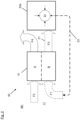
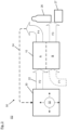
- Figs. 2 and 3 show a production system 40, 50 according to preferred embodiments of the invention.
- the production systems 40, 50 each comprise a CO2 capture device 10 as discussed herein and a production site 30a, 30b configured for farming of plants for food production in this specific example.
- the operational principles of CO2 capturing for farming are shown.
- the capture device 10 of production system 40 depicted in Fig. 2 shows CO2 supply with air from the environment (F2), while the capture device of production system 50 depicted in Fig. 3 shows CO2 extraction from air supplied from production site 30 (F2) for footprint reduction or further usage.
- the CO2 capture device 10 is combined with production site 30a, 30b and operates in two different modes of operation.
- a first operation mode M1 as shown in Fig. 2 , environmental CO2 scrubbing is performed, and supply of the CO2 to the production site 30a for support of plant growth.
- a second operation mode M2 as shown in Fig. 3 , CO2 scrubbing from production site 30b and provision of the CO2 for chemical industry usage is performed.
- the CO2 capture device 10 of production system 40 or at least one of bed thereof is operated in the adsorption mode A, with air supplied from the environment 17 received as air flow F2 through inlet flow channel 18.
- the air flow F2 is pushed by fan 15 through one of the beds 11, 12, e.g. through bed 12 in Fig. 1 .
- the CO2 is adsorbed to the resin 13, and resulting CO2 lean air is emanating as CO2 lean gas flow F4 from capture device 10, and provided to the working environment of employees working at or close to the production site 30a.
- a second bed e.g. bed 11 in Fig. 1
- the bed is supplied with air resupplied from production site 30a to the CO2 capture device 10 through resupply line 23, which directly connects production site 30a to capture device 10.
- the resupplied air enters as gas flow F1 through inlet flow channel 18 into capture device 10, where it is enriched with CO2 when flowing through bed 11.
- the resulting CO2 rich air is supplied as a CO2 rich air flow F3 through outlet channel 20 and a gas supply line 21, which is directly connecting CO2 capture device 10 to production site 30a which forms a CO2 sink 31. There it is consumed by growing plants. Equally, a desorption with a gas flow from the environment 17 or without additional flow and concentrated CO2 is possible.
- Certain farming applications such as mushroom cultivation or fruit storage produce CO2 are forming a CO2 well 32.
- the production system 50 in Fig. 3 comprises a capture device 10 as discussed herein and a production site 30b forming a CO2 well 32, directly connected to each other.
- CO2 rich air taken from the production site 30b is supplied as air flow F2 through inlet flow channel 18 and a gas supply line 22, which is directly connecting capture device 10 to production site 30b, to the adsorber bed, e.g. to bed 12 working or being operated in the adsorption mode A.
- the CO2 is adsorbed to the resin 13, and resulting CO2 lean air is provided through outlet channel 20 as a CO2 lean air flow F4.
- the CO2 lean air flow F4 is resupplied via resupply line 24, which is directly connecting farming application or station 30b with CO2 capture device 10, back to production site 30b and/or to the working environment of the employees working there.
- a second bed e.g. bed 11 in Fig. 1
- Desorbed CO2 taken from capture device 10 through outlet flow channel 20 is provided as a CO2 rich gas flow F3, which may be stored in concentrated form or even be purified by further process station.
- the CO2 may be stored in a storage device, e.g. formed as a bottle 26, and/or supplied to further industrial application, in particular to the chemical industry 27.
- a dedicated purge gas like e.g. hydrogen may be used as a gas flow F1 supplied to capture device 10 for mixing of the CO2 and provision to further processes such as generating power for the processes.
- One example is the use of hydrogen and the supply to a Sabatier reactor for the manufacturing of methane.
- the method according to the invention may comprise one or more of the following features:
Landscapes
- Chemical & Material Sciences (AREA)
- Engineering & Computer Science (AREA)
- Chemical Kinetics & Catalysis (AREA)
- Analytical Chemistry (AREA)
- General Chemical & Material Sciences (AREA)
- Oil, Petroleum & Natural Gas (AREA)
- Environmental & Geological Engineering (AREA)
- Health & Medical Sciences (AREA)
- Biomedical Technology (AREA)
- Organic Chemistry (AREA)
- Life Sciences & Earth Sciences (AREA)
- Environmental Sciences (AREA)
- Solid-Sorbent Or Filter-Aiding Compositions (AREA)
Abstract
Description
- The invention relates to a capture device for removing carbon dioxide (CO2) from air. Further, the invention relates to a production system. In addition, the invention relates to a method for removing CO2 from air.
- The invention is in particular applicable for the food industry like e.g. farming, food production and storage, breweries etc., but also for industrial applications, in particular in the chemical industry, like e.g. for producing components for industrial manufacturing.
- The reduction of CO2 emissions and even the removal of already existing CO2 from the atmosphere is a key driver in the fight against global warming and climate change. Climate change is affecting the world in multiple ways. One problem is that climate change leads to high stress for food production by global warming and the shift of agricultural areas. Thus, one future challenge will be the food supply of the increasing global population under the additional stress of global warming and shifts in the agriculturally suitable areas.
- Greenhouse or indoor farming are potential solutions for sustainable food supply, like e.g. closed loop growing towers and next generation greenhouses. Common greenhouse CO2 supply is either provided via CO2 bottles or by direct utilisation of exhaust gases from combustion engines or from power plants. However, bottles need to be transported, leading to an increasing price, handling effort and CO2 footprint. The use of CO2 from local combustion engines is expensive as well and increases the CO2 footprint. The utilisation of CO2 from power plants limits the deployable radius of the greenhouse.
- CO2 scrubbing devices are used for removal of atmospheric CO2 or closed loop working environments such as submarines or space stations.
- Airbus Defence and Space has e. g. developed a carbon concentration assembly for the use on-board the international space station (ISS). The goal of the system is the removal of the human generated CO2 for a crew of 3 from the environment of the station. The same system has later been adapted for the use on-board of submarines for a crew size up to 70 sailors.
- In the following, some known devices and methods for the removal of CO2 from the atmosphere are shortly discussed.
-
EP 2 397 212 B1 describes a method for regenerating an adsorber on board a submarine, wherein the adsorber is present in the interior of the submarine for binding metabolically generated CO2-containing harmful gases. The thermal energy for regenerating the adsorber is generated by burning a hydrocarbon containing energy carrier with oxygen. At least one combustion product is transferred outboard via the compressor. -
EP 2 965 800 B1 discloses a method for processing biogas of a biogas plant, in which in a method step a membrane process or a reactive process is carried out and in at least one further method step an adsorption and/or absorption process is carried out. -
EP 2 977 093 B1 discloses a method for separating carbon dioxide from a gas mixture that consists of breathing air, with a life sustaining device in a submarine. In a first method step the gas mixture is fed to an adsorption unit under at least one first pressure, wherein a pressure container is used as an adsorption unit. In a second method step a gas mixture is conveyed out of the adsorption unit under a second pressure that is higher than the first pressure. Carbon dioxide is conveyed directly out of the submarine without subsequent densification and without using a compressor. -
EP 3 549 875 A1 describes a regenerative air renewal system for a manned spatial body, with at least one reaction device which is intended to recover oxygen from metabolic carbon dioxide in a cabin of the spatial body. The reaction device is provided for feeding at least part of a substance produced by means of the reaction device to a drive unit of the spatial body. -
EP 3 670 362 A1 discloses a closed environmental compartment with a life support system configured to remove metabolic carbon dioxide from the compartment's interior atmosphere, and with at least one work chamber, which is configured for a performance of an extraction and/or purification process with carbon dioxide as a solvent. The carbon dioxide required for the extraction and/or purification process in the work chamber is supplied by the life support system. The work chamber is connected via lines directly to a line system, in particular for the transport of carbon dioxide, of the life support system. The work chamber is coupled via lines and/or conditioning means directly to the life support system. - It is the object of the invention to provide a method and a device for reducing atmospheric CO2 and improving food supply.
- According to a first aspect, the invention provides a capture device for removing CO2 from air, comprising at least one gas inlet for supplying air into the capture device, at least one bed connected to the gas inlet and comprising solid amine material, a flow generator for generating an air or gas flow through the bed, and at least one gas outlet connected to the bed, wherein the bed is operable in an adsorption mode (A) in which CO2 contained in the air or gas flow is adsorbed by the solid amine material, and in a desorption mode (B) in which CO2 is removed from the solid amine material, wherein the capture device is directly connected
- 1.1. to a production site that consumes CO2 for locally supplying the removed CO2 in the desorption mode, and/or
- 1.2. to a production site that produces CO2 for supplying CO2 lean air obtained in the adsorption mode.
- In particular, the production site that consumes CO2 and/or the production site that produces CO2 is configured for agricultural production. In that case it is for example a farming station or a greenhouse for producing plants, mushrooms, yeast, etc.
- However, the production site that consumes CO2 and/or the production site that produces CO2 may also be an industrial production site, in particular a chemical production site.
- In particular, both types of production sites can be combined to complement each other in a synergetic manner.
- Preferably, the capture device comprises at least a second bed comprising solid amine material.
- The second bed is preferably operable in the adsorption mode and/or in the desorption mode.
- Preferably, at least one of the beds is operable in the adsorption mode while at least another bed is operable in the desorption mode.
- Preferably, the capture device is configured for locally providing CO2 lean air obtained in the adsorption mode to a working environment of people working close-by the production site and/or to the production site that produces CO2.
- Preferably, the capture device comprises a resupply line resupply line for resupplying air from the production site that consumes CO2 to the capture device for further desorption and supplying CO2 enriched air to the production site that consumes CO2.
- Preferably, the capture device is configured for desorption with a gas flow from the environment and/or with a purge gas.
- Preferably, the capture device is configured for supplying the CO2 rich gas and/or the concentrated CO2 to a chemical industry plant when the capture device is providing CO2 lean air to the production site that produces CO2.
- Preferably, the capture device is configured for receiving CO2 rich air from the production site that produces CO2 and supplying the CO2 rich gas to the bed operable in the adsorption mode.
- Preferably, the capture device is configured for activating the desorption by temperature increase of the solid amine material to increase the partial pressure of bound CO2.
- Preferably, the capture device is configured for activating the desorption by evacuation of the bed below the partial pressure of bound CO2.
- According to a second aspect, the invention provides a production system comprising a production site and a capture device according to one of the preceding claims, wherein one or more gas supply lines are directly connecting the production site to the capture device, for supplying CO2 rich gas from the capture device to the production site and/or for supplying CO2 rich gas from the production site to the capture device.
- According to a third aspect, the invention provides a method for removing CO2 from air, comprising: supplying air to a capture device comprising at least one bed comprising solid amine material; generating an air or gas flow through the bed; operating the bed in an adsorption mode in which CO2 contained in the air is adsorbed by the solid amine material, operating the bed in a desorption mode in which CO2 is removed from the solid amine material, locally supplying the CO2 obtained in the desorption mode to a production site that consumes CO2 and/or locally supplying CO2 lean air obtained by the adsorption to a production site that produces CO2.
- Preferably, the method comprises locally providing CO2 lean air obtained in the adsorption mode to a working environment of people working within the production site and/or to the production site that produces CO2.
- Preferably, the desorption is performed by using a gas flow from the environment and/or a purge gas.
- Preferably, the CO2 rich gas and/or the concentrated CO2 is supplied to a chemical industry plant while CO2 lean air is supplied to the production site that produces CO2.
- Preferably, the CO2 rich air is taken from the production site that produces CO2 and used for the adsorption to obtain CO2 lean air, wherein the obtained CO2 lean air is supplied to the production site that produces CO2 rich air.
- Preferably, a thermal swing is performed and/or a pressure swing process is used for adsorption and/or for desorption.
- Preferably, the desorption is activated by temperature increase of the solid amine material to increase the partial pressure of bound CO2.
- Preferably, the desorption is activated by evacuation of the bed below the partial pressure of bound CO2.
- Preferably, a thermal swing desorption is performed using one or more of the processes steam generation, microwave process, induction heating, fluid heating.
- Preferably, a pressure swing process is performed for adsorption, using adsorption at increased pressure and desorption at ambient pressure.
- Preferably, a pressure swing process is performed for desorption, using adsorption at ambient pressure and desorption at a reduced pressure.
- Preferably, the capture device according to the invention and/or the production system according to the invention is used in the method.
- The proposed device and processes herein provides a two fold approach to tackle both problems by reducing atmospheric CO2 and improving plant growth.
- Additionally, the system can also be used to collect CO2 in particular from farming applications such as mushroom cultivation or fruit storage for utilisation in chemical processes to reduce the carbon footprint and close the carbon cycle.
- The invention reduces climate change and global warming, while providing sustainable food supply. The provision of CO2 to greenhouse according to the invention leads to higher yield. In addition, considering other agricultural applications which generate CO2 contributing to global warming, the invention provides CO2 removal and utilisation.
- In particular, the invention provides a combination of the greenhouse application with a CO2 capture device for performing Operation (A), which comprises scrubbing of atmospheric CO2 and supply to the greenhouse for improvement of plant growth and higher yield, and Operation (B), which comprises scrubbing of CO2 from farming application and provision of CO2 for further industrial application.
- In particular, the invention achieves the following advantages:
- Continuous, scalable local CO2 supply without need for CO2 transport or bottle handling.
- Increased degree of freedom, greenhouse location not restricted to spatial vicinity of CO2 generation.
- Provision of CO2 lean air to working environment.
- Capture of atmospheric CO2 and utilisation for plant growth
- Capture of agricultural CO2 and utilisation for chemical industry, closing of carbon cycle.
- Characteristics and advantages described in relation to the capture device and to the production system are also related to the method for removing CO2 from the air or from a gas.
- In the following, exemplary embodiments of the invention showing further advantages and characteristics are described in detail with reference to the figures, in which:
- Fig. 1
- shows a schematic sectional view of a CO2 capture device which may be used in a preferred embodiment of the invention;
- Fig. 2
- shows a schematic flow chart of the method according to a preferred example of the invention, wherein a production site forms a CO2 sink; and
- Fig. 3
- shows a schematic flow chart of the method according to another preferred example of the invention, wherein a production site forms a CO2 well.
- In the figures, similar or identical elements and features are designated by the same reference numbers. The features, functions and advantages discussed herein and shown in the embodiments can be achieved independently and combined in other embodiments. The method steps can be performed in a different order.
-
Fig. 1 shows a carbon dioxide (CO2)capture device 10 used according to a first embodiment of the invention. The CO2 capture device comprises a dedicated number ofbeds solid amine resin 13, in particular e.g. Astrine™. Thedevice 10 is equipped with aflow generator 14 formed by e.g. afan 15 to provide a gas flow F1, F2 through thebeds fan 15 is assigned to onebed - Each
bed inlet flow channel 18 and to anoutlet flow channel 20 having the appropriate sizing for the respective gas or air flow. Eachbed - Each
bed bed 12, a CO2 rich gas flow F2 is pushed through thebed 12 by thefan 15. The CO2 is adsorbed to theresin 13. During desorption B, in this example performed e.g. bybed 11, the CO2 is removed from theresin 13 and transported out of thedevice 10. - If a gas flow is applied during the adsorption phase A, wherein a CO2 rich gas flow F2 is entering the
capture device 10 throughinlet flow channel 18 ofbed 12 and pushed throughbed 12, a CO2 lean gas flow F4 is emanating from thedevice 10 throughoutlet flow channel 20 ofbed 12. - The desorption process B can be activated by two physical principles, or a combination of both. These are thermal swing comprising a temperature increase of the resin to increase the partial pressure of bound CO2, and pressure swing comprising the evacuation of the bed below the partial pressure of bound CO2.
- If a gas flow is applied during the desorption phase B, wherein a CO2 lean gas flow F1 is entering the
capture device 10 e.g. throughinlet flow channel 18 ofbed 11 and pushed throughbed 11 in this example, a CO2 enriched gas flow F3 is emanating from thedevice 10 throughoutlet flow channel 20 ofbed 11. If desorption B is performed without further gases, a concentrated CO2 flow F3 is achieved, which usually may have traces of residual gas from the bed volume. - For a continuous operation a number of at least 3 beds are provided.
-
Figs. 2 and3 show aproduction system production systems CO2 capture device 10 as discussed herein and aproduction site 30a, 30b configured for farming of plants for food production in this specific example. Here, the operational principles of CO2 capturing for farming are shown. - However, the principles shown here in detail are not limited to farming. Other embodiments comprise other industrial applications, in particular for the chemical industy.
- The
capture device 10 ofproduction system 40 depicted inFig. 2 shows CO2 supply with air from the environment (F2), while the capture device ofproduction system 50 depicted inFig. 3 shows CO2 extraction from air supplied from production site 30 (F2) for footprint reduction or further usage. - In both embodiments, the
CO2 capture device 10 is combined withproduction site 30a, 30b and operates in two different modes of operation. - In a first operation mode M1, as shown in
Fig. 2 , environmental CO2 scrubbing is performed, and supply of the CO2 to theproduction site 30a for support of plant growth. In a second operation mode M2, as shown inFig. 3 , CO2 scrubbing from production site 30b and provision of the CO2 for chemical industry usage is performed. - In the following, the operation modes M1 and M2 are described in more detail.
- The
CO2 capture device 10 ofproduction system 40 or at least one of bed thereof is operated in the adsorption mode A, with air supplied from theenvironment 17 received as air flow F2 throughinlet flow channel 18. In thecapture device 10, the air flow F2 is pushed byfan 15 through one of thebeds bed 12 inFig. 1 . The CO2 is adsorbed to theresin 13, and resulting CO2 lean air is emanating as CO2 lean gas flow F4 fromcapture device 10, and provided to the working environment of employees working at or close to theproduction site 30a. - A second bed,
e.g. bed 11 inFig. 1 , is operated in the desorption mode B. The bed is supplied with air resupplied fromproduction site 30a to theCO2 capture device 10 throughresupply line 23, which directly connectsproduction site 30a to capturedevice 10. The resupplied air enters as gas flow F1 throughinlet flow channel 18 intocapture device 10, where it is enriched with CO2 when flowing throughbed 11. - The resulting CO2 rich air is supplied as a CO2 rich air flow F3 through
outlet channel 20 and agas supply line 21, which is directly connectingCO2 capture device 10 toproduction site 30a which forms aCO2 sink 31. There it is consumed by growing plants. Equally, a desorption with a gas flow from theenvironment 17 or without additional flow and concentrated CO2 is possible. - Certain farming applications such as mushroom cultivation or fruit storage produce CO2 are forming a
CO2 well 32. Theproduction system 50 inFig. 3 comprises acapture device 10 as discussed herein and a production site 30b forming aCO2 well 32, directly connected to each other. - CO2 rich air taken from the production site 30b is supplied as air flow F2 through
inlet flow channel 18 and agas supply line 22, which is directly connectingcapture device 10 to production site 30b, to the adsorber bed, e.g. tobed 12 working or being operated in the adsorption mode A. There, the CO2 is adsorbed to theresin 13, and resulting CO2 lean air is provided throughoutlet channel 20 as a CO2 lean air flow F4. The CO2 lean air flow F4 is resupplied viaresupply line 24, which is directly connecting farming application or station 30b withCO2 capture device 10, back to production site 30b and/or to the working environment of the employees working there. - A second bed,
e.g. bed 11 inFig. 1 , is operated in desorption mode B. Desorbed CO2 taken fromcapture device 10 throughoutlet flow channel 20 is provided as a CO2 rich gas flow F3, which may be stored in concentrated form or even be purified by further process station. The CO2 may be stored in a storage device, e.g. formed as abottle 26, and/or supplied to further industrial application, in particular to thechemical industry 27. - A dedicated purge gas like e.g. hydrogen may be used as a gas flow F1 supplied to capture
device 10 for mixing of the CO2 and provision to further processes such as generating power for the processes. One example is the use of hydrogen and the supply to a Sabatier reactor for the manufacturing of methane. - The method according to the invention may comprise one or more of the following features:
- Use of steam generation process for thermal swing desorption.
- Use of microwave process for thermal swing desorption.
- Use of induction heating process for thermal swing desorption, wherein the solid amine resin is e.g. mixed with metal beads.
- Use of electrical heating process for thermal swing desorption.
- Use of thermal fluid heating process for thermal swing desorption.
- Use of pressure swing process for adsorption, adsorption at increased pressure and desorption at ambient pressure.
- Use of pressure swing process for desorption, adsorption at ambient pressure and desorption at reduced pressure.
- Dedicated use for specialised agricultural applications, like e.g. breweries, but also for other industrial applications.
- Particular benefits of the method described herein are:
- Continuous, scalable local CO2 supply without need for CO2 transport or bottle handling.
- Increased degree of freedom, greenhouse location not restricted to spatial vicinity of CO2 generation (e.g. power plant).
- Provision of CO2 lean air to working environment.
- Capture of atmospheric CO2 and utilisation plant growth of capture of agricultural CO2 and utilisation for chemical industry, closing of carbon cycle
-
- 10
- CO2 capture device
- 11, 12
- beds
- 13
- solid amine resin
- 14
- flow generator
- 15
- fan
- 17
- environment
- 18
- inlet flow channel
- 20
-
outlet flow channel 20 - 21
- gas supply line
- 22
- gas supply line
- 23
- resupply line
- 24
- resupply line
- 26
- bottle
- 27
- chemical industry
- 30
- production site
- 31
- CO2 sink
- 32
- CO2 well
- 40, 50
- production system
- A
- adsorption mode
- B
- desorption mode
- F1, F2
- gas flow in
- F3, F4
- gas flow out
- M1, M2
- Operations
Claims (15)
- Capture device for removing CO2 from air, comprisingat least one gas inlet (18) for supplying air into the capture device (10),at least one bed (11, 12) connected to the gas inlet and comprising solid amine material (13),a flow generator (14) for generating an air or gas flow (F1, F2) through the bed (11, 12), andat least one gas outlet (20) connected to the bed (11, 12),wherein the bed (11, 12) is operablein an adsorption mode (A) in which CO2 contained in the air is adsorbed by the solid amine material (13), andin a desorption mode (B) in which CO2 is removed from the solid amine material (13),wherein the capture device (10) is directly connected1.1. to a production site (30a) that consumes CO2 for locally supplying the removed CO2 in the desorption mode (B), and/or1.2. to a production site (30b) that produces CO2 for supplying CO2 lean air obtained in the adsorption mode (A).
- Capture device according to claim 1, characterized in that it comprises at least a second bed (11, 12) operable in the adsorption mode (A) and/or in the desorption mode (B), wherein at least one of the beds (11, 12) is operable in the adsorption mode (A) while at least another one of the beds (11, 12) is operable in the desorption mode (B).
- Capture device according to claim 1 or 2, characterized in that it is configured for locally providing CO2 lean air obtained in the adsorption mode (A) to a working environment of people working at the production site (30a; 30b) and/or to the production site that produces CO2.
- Capture device according to one of the preceding claims, characterized in that the production site (30a; 30b) that produces or consumes CO2 comprises an agricultural production site and/or a chemical production site.
- Capture device according to one of the preceding claims, characterized by a resupply line (23) for resupplying air from the production site (30a) that consumes CO2 to the capture device (10) for further desorption and supplying CO2 enriched air to the production site (30a) that consumes CO2.
- Capture device according to one of the preceding claims, characterized in that it is configured for6.1 desorption with gas flow (F1) from the environment and/or with a purge gas; and/or6.2 supplying the CO2 rich gas and/or the concentrated CO2 to a chemical industry plant (27) when the capture device is providing CO2 lean air to the production site (30b) that produces CO2.
- Capture device according to one of the preceding claims, characterized in that it is configured for receiving CO2 rich air from the production site that produces CO2 and supplying the CO2 rich air from farming to the bed (11, 12) operable in the adsorption mode (A).
- Production system, comprising a production site (30a; 30b) and a capture device (10) according to one of the preceding claims, wherein one or more gas supply lines (21, 23; 22, 24) are directly connecting the production site (30a; 30b) to the capture device (10), for supplying CO2 rich gas (F3) from the capture device (10) to the production site (30a) and/or for supplying CO2 rich gas (F2) from the production site (30b) to the capture device (10).
- Method for removing CO2 from air, comprising:- supplying air to a capture device (10) comprising at least one bed (11,12) comprising solid amine material (13);- generating an air or gas flow (F1, F2) through the bed (11, 12);- operating the bed (11, 12) in an adsorption mode (A) in which CO2 contained in the air is adsorbed by the solid amine material (13),- operating the bed (11, 12) in a desorption mode (B) in which CO2 is removed from the solid amine material (13),- locally supplying the CO2 obtained in the desorption mode (B) to a production site (30a) that consumes CO2 and/or locally supplying CO2 lean air obtained by the adsorption to a production site (30b) that produces CO2.
- Method according to claim 9, characterized by locally providing CO2 lean air obtained in the adsorption mode (A) to a working environment of people working at the production site (30a; 30b) and/or to the production site (30b) that produces CO2.
- Method according to claim 9 or 10, characterized in that the desorption is performed by using a gas flow (F1) from the environment and/or a purge gas.
- Method according to one of claims 9 to 11, characterized in that CO2 rich gas and/or the concentrated CO2 obtained in the desorption mode (B) is supplied to a chemical industry plant (27) while CO2 lean air is supplied to the production site that produces CO2.
- Method according to one of claims 9 to 12, characterized in that CO2 rich air13.1. is taken from the production site (30a) that produces CO2 and used in the adsorption mode (A) to obtain CO2 lean air, wherein the obtained CO2 lean air is resupplied to that production site (30a); and/or13.2. is taken from the production site (30b) that consumes CO2 and used in the desorption mode (B) to obtain the CO2 rich gas and/or concentrated CO2 for supplying it to industrial applications (27).
- Method according to one of claims 9 to 13, characterized in that14.1. the desorption is activated by temperature increase of the solid amine material (13) to increase the partial pressure of bound CO2, and/or14.2. the desorption is activated by evacuation of the bed (11, 12) below the partial pressure of bound CO2; and/or14.3. a thermal swing desorption is performed using one or more of the processes steam generation, microwave process, induction heating, fluid heating, and/or14.4. a pressure swing process is performed for adsorption, using adsorption at increased pressure and desorption at ambient pressure, and/or14.5. a pressure swing process is performed for desorption, using adsorption at ambient pressure and desorption at a reduced pressure.
- Method according to one of claims 9 to 14, characterized by using the capture device (10) according to one of claims 1 to 7 and/or the production system (30a; 30b) according to claim 8.
Priority Applications (1)
| Application Number | Priority Date | Filing Date | Title |
|---|---|---|---|
| EP22166694.4A EP4257226A1 (en) | 2022-04-05 | 2022-04-05 | Capture device and method for removing co2 from air, and production system |
Applications Claiming Priority (1)
| Application Number | Priority Date | Filing Date | Title |
|---|---|---|---|
| EP22166694.4A EP4257226A1 (en) | 2022-04-05 | 2022-04-05 | Capture device and method for removing co2 from air, and production system |
Publications (1)
| Publication Number | Publication Date |
|---|---|
| EP4257226A1 true EP4257226A1 (en) | 2023-10-11 |
Family
ID=81327984
Family Applications (1)
| Application Number | Title | Priority Date | Filing Date |
|---|---|---|---|
| EP22166694.4A Pending EP4257226A1 (en) | 2022-04-05 | 2022-04-05 | Capture device and method for removing co2 from air, and production system |
Country Status (1)
| Country | Link |
|---|---|
| EP (1) | EP4257226A1 (en) |
Citations (8)
| Publication number | Priority date | Publication date | Assignee | Title |
|---|---|---|---|---|
| EP2397212B1 (en) | 2010-06-15 | 2014-05-21 | Astrium GmbH | Method for regenerating an adsorber or absorber |
| WO2016037668A1 (en) * | 2014-09-12 | 2016-03-17 | Giaura Bv | Method and device for the reversible adsorption of carbon dioxide |
| EP2965800B1 (en) | 2014-07-08 | 2019-01-30 | Airbus Defence and Space GmbH | Method and device for treating gas |
| EP3549875A1 (en) | 2018-04-06 | 2019-10-09 | Airbus Defence and Space GmbH | Regenerative air renewal system for a manned spacecraft |
| EP3670362A1 (en) | 2018-12-21 | 2020-06-24 | Airbus Defence and Space | Closed environmental compartment to accommodate humans |
| US20210120750A1 (en) * | 2018-02-16 | 2021-04-29 | Carbon Sink, Inc. | Fluidized bed extractors for capture of co2 from ambient air |
| EP2977093B1 (en) | 2014-07-25 | 2021-05-05 | Airbus Defence and Space GmbH | Method for separating carbon dioxide from breathing air of a submarine |
| WO2022020634A1 (en) * | 2020-07-22 | 2022-01-27 | Matthew Atwood | Apparatus, method and system for direct air capture utilizing electromagnetic excitation radiation desorption of solid amine sorbents to release carbon dioxide |
-
2022
- 2022-04-05 EP EP22166694.4A patent/EP4257226A1/en active Pending
Patent Citations (8)
| Publication number | Priority date | Publication date | Assignee | Title |
|---|---|---|---|---|
| EP2397212B1 (en) | 2010-06-15 | 2014-05-21 | Astrium GmbH | Method for regenerating an adsorber or absorber |
| EP2965800B1 (en) | 2014-07-08 | 2019-01-30 | Airbus Defence and Space GmbH | Method and device for treating gas |
| EP2977093B1 (en) | 2014-07-25 | 2021-05-05 | Airbus Defence and Space GmbH | Method for separating carbon dioxide from breathing air of a submarine |
| WO2016037668A1 (en) * | 2014-09-12 | 2016-03-17 | Giaura Bv | Method and device for the reversible adsorption of carbon dioxide |
| US20210120750A1 (en) * | 2018-02-16 | 2021-04-29 | Carbon Sink, Inc. | Fluidized bed extractors for capture of co2 from ambient air |
| EP3549875A1 (en) | 2018-04-06 | 2019-10-09 | Airbus Defence and Space GmbH | Regenerative air renewal system for a manned spacecraft |
| EP3670362A1 (en) | 2018-12-21 | 2020-06-24 | Airbus Defence and Space | Closed environmental compartment to accommodate humans |
| WO2022020634A1 (en) * | 2020-07-22 | 2022-01-27 | Matthew Atwood | Apparatus, method and system for direct air capture utilizing electromagnetic excitation radiation desorption of solid amine sorbents to release carbon dioxide |
Non-Patent Citations (1)
| Title |
|---|
| GHIAT IKHLAS ET AL: "CO2 utilisation in agricultural greenhouses: A novel 'plant to plant' approach driven by bioenergy with carbon capture systems within the energy, water and food Nexus", ENERGY CONVERSION AND MANAGEMENT, ELSEVIER SCIENCE PUBLISHERS, OXFORD, GB, vol. 228, 29 November 2020 (2020-11-29), XP086438565, ISSN: 0196-8904, [retrieved on 20201129], DOI: 10.1016/J.ENCONMAN.2020.113668 * |
Similar Documents
| Publication | Publication Date | Title |
|---|---|---|
| US11655147B2 (en) | System and method for generating hydrogen through ammonia adsorption | |
| US9555360B2 (en) | Method of making a reformate from a gaseous VOC stream | |
| EP1639233B1 (en) | Using voc as fuel for an engine | |
| US20050109207A1 (en) | Method and apparatus for the recovery of volatile organic compounds and concentration thereof | |
| CA3033841C (en) | Method for recovering hydrogen from biomass pyrolysis gas | |
| US20200317526A1 (en) | Processes for converting carbon dioxide | |
| WO2022235664A3 (en) | Systems and processes for removal of carbon dioxide (co2) from co2-containing gases using alkali metal adsorbents | |
| CN103626177A (en) | System and method for processing greenhouse gases | |
| JP2021049482A (en) | Method for production of refined gas, and gas purifier | |
| EP3369703A1 (en) | Hydrogen recovery method | |
| EP0294036A3 (en) | Conditioning of the atmosphere over perishable goods | |
| Perry et al. | Air purification in closed environments: overview of spacecraft systems | |
| US10350537B2 (en) | High purity nitrogen/hydrogen production from an exhaust stream | |
| JP2000143204A (en) | Carbon separator for carbon-containing fuel | |
| US20150144364A1 (en) | Operator-Portable Power Supply of Maximum Specific Energy | |
| US20220177827A1 (en) | Biogas plant and biogas treatment | |
| Franco et al. | Study of Sabatier Catalyst Performance for a Mars ISRU Propellant Production Plant | |
| KR20240106114A (en) | Hydrogen Extraction System Using Ammonia with Improved System Efficiency | |
| Perry et al. | Atmosphere revitalization technology development for crewed space exploration | |
| JP2000072404A (en) | Production of hydrogen-nitrogen gaseous mixture and device therefor | |
| O’Sullivan et al. | Review of carbon dioxide removal and recycling in space | |
| WO2013090279A4 (en) | Devices and methods for reducing oxygen infiltration | |
| KR20260048867A (en) | Boil-off gas processing and inert gas supply system and liquefied gas carrier | |
| WO2024219979A1 (en) | Systems and methods relating to direct air capture of co2 | |
| Marshall et al. | Evaluation of an electrochemical N2/H2 gas separator |
Legal Events
| Date | Code | Title | Description |
|---|---|---|---|
| PUAI | Public reference made under article 153(3) epc to a published international application that has entered the european phase |
Free format text: ORIGINAL CODE: 0009012 |
|
| STAA | Information on the status of an ep patent application or granted ep patent |
Free format text: STATUS: THE APPLICATION HAS BEEN PUBLISHED |
|
| AK | Designated contracting states |
Kind code of ref document: A1 Designated state(s): AL AT BE BG CH CY CZ DE DK EE ES FI FR GB GR HR HU IE IS IT LI LT LU LV MC MK MT NL NO PL PT RO RS SE SI SK SM TR |
|
| STAA | Information on the status of an ep patent application or granted ep patent |
Free format text: STATUS: REQUEST FOR EXAMINATION WAS MADE |
|
| 17P | Request for examination filed |
Effective date: 20240411 |
|
| RBV | Designated contracting states (corrected) |
Designated state(s): AL AT BE BG CH CY CZ DE DK EE ES FI FR GB GR HR HU IE IS IT LI LT LU LV MC MK MT NL NO PL PT RO RS SE SI SK SM TR |
|
| RAP1 | Party data changed (applicant data changed or rights of an application transferred) |
Owner name: AIRBUS OPERATIONS GMBH |