EP2965800B1 - Verfahren und Vorrichtung zu einer Gasaufbereitung - Google Patents
Verfahren und Vorrichtung zu einer Gasaufbereitung Download PDFInfo
- Publication number
- EP2965800B1 EP2965800B1 EP14176209.6A EP14176209A EP2965800B1 EP 2965800 B1 EP2965800 B1 EP 2965800B1 EP 14176209 A EP14176209 A EP 14176209A EP 2965800 B1 EP2965800 B1 EP 2965800B1
- Authority
- EP
- European Patent Office
- Prior art keywords
- absorption
- adsorption
- gas
- plant
- power
- Prior art date
- Legal status (The legal status is an assumption and is not a legal conclusion. Google has not performed a legal analysis and makes no representation as to the accuracy of the status listed.)
- Active
Links
Images




Classifications
-
- B—PERFORMING OPERATIONS; TRANSPORTING
- B01—PHYSICAL OR CHEMICAL PROCESSES OR APPARATUS IN GENERAL
- B01D—SEPARATION
- B01D53/00—Separation of gases or vapours; Recovering vapours of volatile solvents from gases; Chemical or biological purification of waste gases, e.g. engine exhaust gases, smoke, fumes, flue gases, aerosols
- B01D53/02—Separation of gases or vapours; Recovering vapours of volatile solvents from gases; Chemical or biological purification of waste gases, e.g. engine exhaust gases, smoke, fumes, flue gases, aerosols by adsorption, e.g. preparative gas chromatography
- B01D53/04—Separation of gases or vapours; Recovering vapours of volatile solvents from gases; Chemical or biological purification of waste gases, e.g. engine exhaust gases, smoke, fumes, flue gases, aerosols by adsorption, e.g. preparative gas chromatography with stationary adsorbents
- B01D53/0462—Temperature swing adsorption
-
- C—CHEMISTRY; METALLURGY
- C07—ORGANIC CHEMISTRY
- C07C—ACYCLIC OR CARBOCYCLIC COMPOUNDS
- C07C1/00—Preparation of hydrocarbons from one or more compounds, none of them being a hydrocarbon
- C07C1/02—Preparation of hydrocarbons from one or more compounds, none of them being a hydrocarbon from oxides of a carbon
- C07C1/12—Preparation of hydrocarbons from one or more compounds, none of them being a hydrocarbon from oxides of a carbon from carbon dioxide with hydrogen
-
- B—PERFORMING OPERATIONS; TRANSPORTING
- B01—PHYSICAL OR CHEMICAL PROCESSES OR APPARATUS IN GENERAL
- B01D—SEPARATION
- B01D53/00—Separation of gases or vapours; Recovering vapours of volatile solvents from gases; Chemical or biological purification of waste gases, e.g. engine exhaust gases, smoke, fumes, flue gases, aerosols
- B01D53/02—Separation of gases or vapours; Recovering vapours of volatile solvents from gases; Chemical or biological purification of waste gases, e.g. engine exhaust gases, smoke, fumes, flue gases, aerosols by adsorption, e.g. preparative gas chromatography
- B01D53/04—Separation of gases or vapours; Recovering vapours of volatile solvents from gases; Chemical or biological purification of waste gases, e.g. engine exhaust gases, smoke, fumes, flue gases, aerosols by adsorption, e.g. preparative gas chromatography with stationary adsorbents
-
- B—PERFORMING OPERATIONS; TRANSPORTING
- B01—PHYSICAL OR CHEMICAL PROCESSES OR APPARATUS IN GENERAL
- B01D—SEPARATION
- B01D53/00—Separation of gases or vapours; Recovering vapours of volatile solvents from gases; Chemical or biological purification of waste gases, e.g. engine exhaust gases, smoke, fumes, flue gases, aerosols
- B01D53/02—Separation of gases or vapours; Recovering vapours of volatile solvents from gases; Chemical or biological purification of waste gases, e.g. engine exhaust gases, smoke, fumes, flue gases, aerosols by adsorption, e.g. preparative gas chromatography
- B01D53/04—Separation of gases or vapours; Recovering vapours of volatile solvents from gases; Chemical or biological purification of waste gases, e.g. engine exhaust gases, smoke, fumes, flue gases, aerosols by adsorption, e.g. preparative gas chromatography with stationary adsorbents
- B01D53/047—Pressure swing adsorption
-
- B—PERFORMING OPERATIONS; TRANSPORTING
- B01—PHYSICAL OR CHEMICAL PROCESSES OR APPARATUS IN GENERAL
- B01D—SEPARATION
- B01D53/00—Separation of gases or vapours; Recovering vapours of volatile solvents from gases; Chemical or biological purification of waste gases, e.g. engine exhaust gases, smoke, fumes, flue gases, aerosols
- B01D53/14—Separation of gases or vapours; Recovering vapours of volatile solvents from gases; Chemical or biological purification of waste gases, e.g. engine exhaust gases, smoke, fumes, flue gases, aerosols by absorption
- B01D53/1425—Regeneration of liquid absorbents
-
- B—PERFORMING OPERATIONS; TRANSPORTING
- B01—PHYSICAL OR CHEMICAL PROCESSES OR APPARATUS IN GENERAL
- B01D—SEPARATION
- B01D53/00—Separation of gases or vapours; Recovering vapours of volatile solvents from gases; Chemical or biological purification of waste gases, e.g. engine exhaust gases, smoke, fumes, flue gases, aerosols
- B01D53/14—Separation of gases or vapours; Recovering vapours of volatile solvents from gases; Chemical or biological purification of waste gases, e.g. engine exhaust gases, smoke, fumes, flue gases, aerosols by absorption
- B01D53/1431—Pretreatment by other processes
- B01D53/1443—Pretreatment by diffusion
-
- B—PERFORMING OPERATIONS; TRANSPORTING
- B01—PHYSICAL OR CHEMICAL PROCESSES OR APPARATUS IN GENERAL
- B01D—SEPARATION
- B01D53/00—Separation of gases or vapours; Recovering vapours of volatile solvents from gases; Chemical or biological purification of waste gases, e.g. engine exhaust gases, smoke, fumes, flue gases, aerosols
- B01D53/14—Separation of gases or vapours; Recovering vapours of volatile solvents from gases; Chemical or biological purification of waste gases, e.g. engine exhaust gases, smoke, fumes, flue gases, aerosols by absorption
- B01D53/1493—Selection of liquid materials for use as absorbents
-
- B—PERFORMING OPERATIONS; TRANSPORTING
- B01—PHYSICAL OR CHEMICAL PROCESSES OR APPARATUS IN GENERAL
- B01D—SEPARATION
- B01D53/00—Separation of gases or vapours; Recovering vapours of volatile solvents from gases; Chemical or biological purification of waste gases, e.g. engine exhaust gases, smoke, fumes, flue gases, aerosols
- B01D53/22—Separation of gases or vapours; Recovering vapours of volatile solvents from gases; Chemical or biological purification of waste gases, e.g. engine exhaust gases, smoke, fumes, flue gases, aerosols by diffusion
- B01D53/229—Integrated processes (Diffusion and at least one other process, e.g. adsorption, absorption)
-
- B—PERFORMING OPERATIONS; TRANSPORTING
- B01—PHYSICAL OR CHEMICAL PROCESSES OR APPARATUS IN GENERAL
- B01D—SEPARATION
- B01D63/00—Apparatus in general for separation processes using semi-permeable membranes
-
- C—CHEMISTRY; METALLURGY
- C07—ORGANIC CHEMISTRY
- C07C—ACYCLIC OR CARBOCYCLIC COMPOUNDS
- C07C7/00—Purification; Separation; Use of additives
- C07C7/11—Purification; Separation; Use of additives by absorption, i.e. purification or separation of gaseous hydrocarbons with the aid of liquids
-
- C—CHEMISTRY; METALLURGY
- C07—ORGANIC CHEMISTRY
- C07C—ACYCLIC OR CARBOCYCLIC COMPOUNDS
- C07C7/00—Purification; Separation; Use of additives
- C07C7/12—Purification; Separation; Use of additives by adsorption, i.e. purification or separation of hydrocarbons with the aid of solids, e.g. with ion-exchangers
-
- C—CHEMISTRY; METALLURGY
- C10—PETROLEUM, GAS OR COKE INDUSTRIES; TECHNICAL GASES CONTAINING CARBON MONOXIDE; FUELS; LUBRICANTS; PEAT
- C10L—FUELS NOT OTHERWISE PROVIDED FOR; NATURAL GAS; SYNTHETIC NATURAL GAS OBTAINED BY PROCESSES NOT COVERED BY SUBCLASSES C10G OR C10K; LIQUIFIED PETROLEUM GAS; USE OF ADDITIVES TO FUELS OR FIRES; FIRE-LIGHTERS
- C10L3/00—Gaseous fuels; Natural gas; Synthetic natural gas obtained by processes not covered by subclass C10G, C10K; Liquefied petroleum gas
- C10L3/06—Natural gas; Synthetic natural gas obtained by processes not covered by C10G, C10K3/02 or C10K3/04
- C10L3/08—Production of synthetic natural gas
-
- C—CHEMISTRY; METALLURGY
- C10—PETROLEUM, GAS OR COKE INDUSTRIES; TECHNICAL GASES CONTAINING CARBON MONOXIDE; FUELS; LUBRICANTS; PEAT
- C10L—FUELS NOT OTHERWISE PROVIDED FOR; NATURAL GAS; SYNTHETIC NATURAL GAS OBTAINED BY PROCESSES NOT COVERED BY SUBCLASSES C10G OR C10K; LIQUIFIED PETROLEUM GAS; USE OF ADDITIVES TO FUELS OR FIRES; FIRE-LIGHTERS
- C10L3/00—Gaseous fuels; Natural gas; Synthetic natural gas obtained by processes not covered by subclass C10G, C10K; Liquefied petroleum gas
- C10L3/06—Natural gas; Synthetic natural gas obtained by processes not covered by C10G, C10K3/02 or C10K3/04
- C10L3/10—Working-up natural gas or synthetic natural gas
- C10L3/101—Removal of contaminants
- C10L3/102—Removal of contaminants of acid contaminants
- C10L3/104—Carbon dioxide
-
- C—CHEMISTRY; METALLURGY
- C12—BIOCHEMISTRY; BEER; SPIRITS; WINE; VINEGAR; MICROBIOLOGY; ENZYMOLOGY; MUTATION OR GENETIC ENGINEERING
- C12M—APPARATUS FOR ENZYMOLOGY OR MICROBIOLOGY; APPARATUS FOR CULTURING MICROORGANISMS FOR PRODUCING BIOMASS, FOR GROWING CELLS OR FOR OBTAINING FERMENTATION OR METABOLIC PRODUCTS, i.e. BIOREACTORS OR FERMENTERS
- C12M47/00—Means for after-treatment of the produced biomass or of the fermentation or metabolic products, e.g. storage of biomass
- C12M47/18—Gas cleaning, e.g. scrubbers; Separation of different gases
-
- B—PERFORMING OPERATIONS; TRANSPORTING
- B01—PHYSICAL OR CHEMICAL PROCESSES OR APPARATUS IN GENERAL
- B01D—SEPARATION
- B01D53/00—Separation of gases or vapours; Recovering vapours of volatile solvents from gases; Chemical or biological purification of waste gases, e.g. engine exhaust gases, smoke, fumes, flue gases, aerosols
- B01D53/22—Separation of gases or vapours; Recovering vapours of volatile solvents from gases; Chemical or biological purification of waste gases, e.g. engine exhaust gases, smoke, fumes, flue gases, aerosols by diffusion
- B01D2053/221—Devices
-
- B—PERFORMING OPERATIONS; TRANSPORTING
- B01—PHYSICAL OR CHEMICAL PROCESSES OR APPARATUS IN GENERAL
- B01D—SEPARATION
- B01D2252/00—Absorbents, i.e. solvents and liquid materials for gas absorption
- B01D2252/20—Organic absorbents
- B01D2252/204—Amines
-
- B—PERFORMING OPERATIONS; TRANSPORTING
- B01—PHYSICAL OR CHEMICAL PROCESSES OR APPARATUS IN GENERAL
- B01D—SEPARATION
- B01D2253/00—Adsorbents used in seperation treatment of gases and vapours
- B01D2253/20—Organic adsorbents
-
- B—PERFORMING OPERATIONS; TRANSPORTING
- B01—PHYSICAL OR CHEMICAL PROCESSES OR APPARATUS IN GENERAL
- B01D—SEPARATION
- B01D2256/00—Main component in the product gas stream after treatment
- B01D2256/24—Hydrocarbons
- B01D2256/245—Methane
-
- B—PERFORMING OPERATIONS; TRANSPORTING
- B01—PHYSICAL OR CHEMICAL PROCESSES OR APPARATUS IN GENERAL
- B01D—SEPARATION
- B01D2257/00—Components to be removed
- B01D2257/50—Carbon oxides
- B01D2257/504—Carbon dioxide
-
- B—PERFORMING OPERATIONS; TRANSPORTING
- B01—PHYSICAL OR CHEMICAL PROCESSES OR APPARATUS IN GENERAL
- B01D—SEPARATION
- B01D2258/00—Sources of waste gases
- B01D2258/05—Biogas
-
- B—PERFORMING OPERATIONS; TRANSPORTING
- B01—PHYSICAL OR CHEMICAL PROCESSES OR APPARATUS IN GENERAL
- B01D—SEPARATION
- B01D2259/00—Type of treatment
- B01D2259/40—Further details for adsorption processes and devices
- B01D2259/40083—Regeneration of adsorbents in processes other than pressure or temperature swing adsorption
- B01D2259/40088—Regeneration of adsorbents in processes other than pressure or temperature swing adsorption by heating
-
- B—PERFORMING OPERATIONS; TRANSPORTING
- B01—PHYSICAL OR CHEMICAL PROCESSES OR APPARATUS IN GENERAL
- B01D—SEPARATION
- B01D2259/00—Type of treatment
- B01D2259/65—Employing advanced heat integration, e.g. Pinch technology
-
- B—PERFORMING OPERATIONS; TRANSPORTING
- B01—PHYSICAL OR CHEMICAL PROCESSES OR APPARATUS IN GENERAL
- B01D—SEPARATION
- B01D2313/00—Details relating to membrane modules or apparatus
- B01D2313/40—Adsorbents within the flow path
-
- B—PERFORMING OPERATIONS; TRANSPORTING
- B01—PHYSICAL OR CHEMICAL PROCESSES OR APPARATUS IN GENERAL
- B01D—SEPARATION
- B01D53/00—Separation of gases or vapours; Recovering vapours of volatile solvents from gases; Chemical or biological purification of waste gases, e.g. engine exhaust gases, smoke, fumes, flue gases, aerosols
- B01D53/02—Separation of gases or vapours; Recovering vapours of volatile solvents from gases; Chemical or biological purification of waste gases, e.g. engine exhaust gases, smoke, fumes, flue gases, aerosols by adsorption, e.g. preparative gas chromatography
- B01D53/04—Separation of gases or vapours; Recovering vapours of volatile solvents from gases; Chemical or biological purification of waste gases, e.g. engine exhaust gases, smoke, fumes, flue gases, aerosols by adsorption, e.g. preparative gas chromatography with stationary adsorbents
- B01D53/0407—Constructional details of adsorbing systems
- B01D53/0438—Cooling or heating systems
-
- Y—GENERAL TAGGING OF NEW TECHNOLOGICAL DEVELOPMENTS; GENERAL TAGGING OF CROSS-SECTIONAL TECHNOLOGIES SPANNING OVER SEVERAL SECTIONS OF THE IPC; TECHNICAL SUBJECTS COVERED BY FORMER USPC CROSS-REFERENCE ART COLLECTIONS [XRACs] AND DIGESTS
- Y02—TECHNOLOGIES OR APPLICATIONS FOR MITIGATION OR ADAPTATION AGAINST CLIMATE CHANGE
- Y02C—CAPTURE, STORAGE, SEQUESTRATION OR DISPOSAL OF GREENHOUSE GASES [GHG]
- Y02C20/00—Capture or disposal of greenhouse gases
- Y02C20/40—Capture or disposal of greenhouse gases of CO2
-
- Y—GENERAL TAGGING OF NEW TECHNOLOGICAL DEVELOPMENTS; GENERAL TAGGING OF CROSS-SECTIONAL TECHNOLOGIES SPANNING OVER SEVERAL SECTIONS OF THE IPC; TECHNICAL SUBJECTS COVERED BY FORMER USPC CROSS-REFERENCE ART COLLECTIONS [XRACs] AND DIGESTS
- Y02—TECHNOLOGIES OR APPLICATIONS FOR MITIGATION OR ADAPTATION AGAINST CLIMATE CHANGE
- Y02E—REDUCTION OF GREENHOUSE GAS [GHG] EMISSIONS, RELATED TO ENERGY GENERATION, TRANSMISSION OR DISTRIBUTION
- Y02E50/00—Technologies for the production of fuel of non-fossil origin
- Y02E50/30—Fuel from waste, e.g. synthetic alcohol or diesel
-
- Y—GENERAL TAGGING OF NEW TECHNOLOGICAL DEVELOPMENTS; GENERAL TAGGING OF CROSS-SECTIONAL TECHNOLOGIES SPANNING OVER SEVERAL SECTIONS OF THE IPC; TECHNICAL SUBJECTS COVERED BY FORMER USPC CROSS-REFERENCE ART COLLECTIONS [XRACs] AND DIGESTS
- Y02—TECHNOLOGIES OR APPLICATIONS FOR MITIGATION OR ADAPTATION AGAINST CLIMATE CHANGE
- Y02P—CLIMATE CHANGE MITIGATION TECHNOLOGIES IN THE PRODUCTION OR PROCESSING OF GOODS
- Y02P20/00—Technologies relating to chemical industry
- Y02P20/151—Reduction of greenhouse gas [GHG] emissions, e.g. CO2
-
- Y—GENERAL TAGGING OF NEW TECHNOLOGICAL DEVELOPMENTS; GENERAL TAGGING OF CROSS-SECTIONAL TECHNOLOGIES SPANNING OVER SEVERAL SECTIONS OF THE IPC; TECHNICAL SUBJECTS COVERED BY FORMER USPC CROSS-REFERENCE ART COLLECTIONS [XRACs] AND DIGESTS
- Y02—TECHNOLOGIES OR APPLICATIONS FOR MITIGATION OR ADAPTATION AGAINST CLIMATE CHANGE
- Y02P—CLIMATE CHANGE MITIGATION TECHNOLOGIES IN THE PRODUCTION OR PROCESSING OF GOODS
- Y02P20/00—Technologies relating to chemical industry
- Y02P20/50—Improvements relating to the production of bulk chemicals
- Y02P20/59—Biological synthesis; Biological purification
Definitions
- An object of the invention is in particular to provide a method with a high efficiency and / or a method which allows a compact device.
- the object is achieved by the features of claim 1, while advantageous embodiments and refinements of the invention can be taken from the dependent claims and an independent claim.
- a method for the treatment of biogas in a biogas plant in which a membrane process in a membrane unit is carried out in a process step for CO 2 separation from the biogas and in a further downstream process step an adsorption and / or absorption process in absorption units , for gas purification to achieve a methane purity of greater than 99.5 vol.% Is performed, wherein the adsorption and / or absorption process is carried out as a post-purification, wherein in the adsorption and / or absorption process, a solid state adsorber and / or a solid state absorber is used , a solid amine, wherein in a further process step, a reactive process in which in a power-to-gas plant in a catalytically activated chemical process, a methane-rich gas mixture is generated, is carried out, wherein in the power-to-gas plant electrical energy from a plant, in particular a wind turbine and / or a solar system, is used to produce hydrogen by means of electro
- adsorption and / or absorption process is carried out in a "further process step" should in this context be understood in particular to mean that an adsorption and / or absorption material is separated, in particular at a distance, in particular with a distance greater than 1 cm, from a diaphragm is arranged and / or that the method steps are also separately operable separately.
- a "reactive process” should be understood as meaning, in particular, a process in which, in particular, a catalytically activated chemical process or in a biological process, in particular with a nutrient substrate, a gas mixture is generated, in particular an at least methane-rich gas mixture.
- At least one methane-rich gas mixture is generated from a CO 2 source in the reactive process in a power-to-gas plant.
- Biogas is preferably used as CO 2 source.
- a "power-to-gas plant” is to be understood in particular as a plant in which electrical energy from a plant, such as in particular a wind turbine and / or a solar system, is used to produce hydrogen by means of electrolysis. This hydrogen is then used in particular to produce methane together with carbon dioxide, in particular from a biogas plant or from another CO 2 source, by means of a catalyst.
- the methane can, in particular after CO 2 gas purification with the adsorption and / or absorption unit and a methane drying, be fed into a natural gas network.
- the adsorption and / or absorption unit preferably also assumes the function of residual methane drying to very low dew point temperatures in the product gas methane, in addition to CO 2 gas purification.
- a particularly simple membrane module interconnection can be achieved, and particularly high gas qualities, in particular bio natural gas qualities, with a methane purity of greater than 99.5 vol.%, Can be achieved, in particular if the adsorption and / or absorption process is carried out as a post-purification is carried out, wherein the adsorption and / or absorption process is carried out in particular as a fine cleaning, in which preferably a depletion of a carbon dioxide concentration in the process gas to less than 0.3% by volume of CO 2 is performed.
- the adsorption and / or absorption process can be used to prepare the retentate and / or the permeate of a membrane module, ie with corresponding high or low pressures.
- bio natural gas should be understood in this context, in particular methane, which is not of fossil origin, but was produced from biogenic substances.
- a particularly high gas quality especially bio natural gas qualities with a methane purity of greater than 99.5 vol.%
- the reactive process as catalytic methanation process is carried out and the CO 2 contained in the bio natural gas with H 2 from a power-to-gas plant is catalytically converted to methane and water and then an adsorption and / or absorption process is carried out as a post-purification, wherein the adsorption and / or Absorption process is carried out in particular as a fine cleaning, in which preferably a depletion of a carbon dioxide concentration in the process gas to less than 0.3 vol .-% CO 2 is performed.
- various adsorber and / or absorber materials that appear appropriate to the person skilled in the art are conceivable, such as in particular liquid or gaseous adsorbent and / or absorber materials.
- at least one solid-state adsorber and / or one solid-state absorber very particularly preferably an absorber resin and / or adsorber resin.
- Particularly suitable is an amine, preferably a solid amine.
- the absorption and / or adsorption material preferably has a selectivity at standard conditions, ie at a temperature of 25 ° C. and a pressure of 1 bar abs , greater than 100, more preferably greater than 150 and more preferably greater than 200.
- a “selectivity” is to be understood as meaning a loading ratio, in particular a solid-amine loading ratio, in particular a loading ratio between CO 2 and CH 4 .
- the absorption and / or adsorption material is preferably used in the form of a bed.
- a "bed” is to be understood in particular as meaning that the material is present in a granular and / or else lumpy mixture which is present in a pourable form.
- a solid amine advantageously low regeneration temperatures can be achieved, which particularly advantageous waste heat of Other units, such as in particular a cogeneration unit (CHP), a membrane unit and / or a power-to-gas plant can be used.
- CHP cogeneration unit
- a membrane unit and / or a power-to-gas plant can be used.
- a long service life and a particularly high gas purity can be achieved.
- molecular sieves for example of activated carbon, etc., are also conceivable.
- At least one adsorption and / or absorption unit is cooled or heated in at least one method step, whereby the adsorption and / or absorption process and / or a regeneration process can be supported particularly advantageous.
- cooled or “heated” is to be understood in particular that actively, in particular with a third unit, heat dissipated or heat is supplied.
- a so-called temperature swing adsorption and / or absorption is carried out, in which at a low temperature adsorption and / or absorption is carried out and at a higher temperature regeneration is carried out.
- the adsorption and / or absorption takes place advantageously at a temperature less than 40 ° C, preferably less than 30 ° C and most preferably less than 20 ° C, while the regeneration advantageously at a temperature greater than 70 °, preferably at a Temperature greater than 80 ° C and most preferably greater than 90 ° C is performed. Preferably, however, the regeneration is carried out at a temperature lower than 120 ° C.
- a methane recovery is realized by means of a vacuum pump.
- heat energy is transferred from at least one adsorption and / or absorption unit to at least one further adsorption and / or absorption unit and / or pressure energy is transferred from at least one adsorption and / or absorption unit to at least one further adsorption and / or absorption unit
- can an advantageous heat integration or pressure integration saves energy and high efficiency can be achieved.
- several adsorption and / or absorption units are interconnected.
- the adsorption and / or absorption units are alternately printed or evacuated. It is advantageously carried out a so-called pressure swing adsorption and / or absorption, in which at a higher pressure adsorption and / or Absorption is performed and at a lower pressure regeneration is performed.
- exhaust heat is used for temperature control, ie cooling and / or heating, of an adsorption and / or absorption unit, in particular waste heat of a power plant, in particular of a combined heat and power plant, and / or waste heat of the membrane process and / or very particularly preferably from a power-to-gas plant, which in turn saves energy.
- the waste heat preferably an electrolyzer and / or released heat of reaction of the catalytic methanation can be used to regenerate an adsorber and absorber material.
- adsorption and / or absorption units interconnected and a heat integration of the adsorption and / or absorption units by means of a circulating heat transfer fluid with each other and / or in combination with a combined heat and power plant and / or with a membrane unit and / or with the power-to -Gas plant realized.
- An accumulating adsorption and / or absorption heat during CO 2 adsorption and / or absorption can advantageously be supplied to the biogas plant.
- At least one adsorption and / or absorption unit is supplied with hydrogen, in particular from a power-to-gas plant.
- the hydrogen is preferably introduced during a regeneration in the adsorption and / or absorption unit, whereby the regeneration can be carried out particularly efficiently, in particular due to an achievable improved thermal conductivity of an adsorption and / or absorption material under a H 2 atmosphere, and although preferably due to an improved thermal conductivity of an adsorption and / or Absorptionsharz thoroughlyung.
- Regeneration preferably takes place at elevated levels Pressure, ie in particular at a pressure greater than 2 bar abs . and particularly advantageously greater than 4 bar abs . and under a H2 atmosphere instead.
- the educts H 2 and CO 2 are preferably delivered at such a high pressure level at the end of a desorption to the power-to-gas plant, that in a subsequent methanation, the product gas methane can be fed directly into the natural gas without recompression.
- an increase in pressure prior to electrolysis within the power-to-gas system can be achieved in an especially energy-efficient manner.
- Regeneration without hydrogen supply to the adsorption and / or absorption unit preferably takes place at a pressure of less than 1.5 bar abs . instead of.
- the adsorption and / or absorption unit and in particular an adsorption and / or absorption resin bed located therein can advantageously assume a function of a CO 2 storage and a gas premix for a subsequent methanation in the power-to-gas system. Furthermore, the educts CO 2 and H 2 can be obtained for the methanization at elevated pressure, which has a favorable effect on an equilibrium position and an achievable conversion of the methanation.
- the regeneration of the adsorption and / or absorption unit and in particular the regeneration of an adsorption and / or Absorptionsharz intendedung under a hydrogen atmosphere is advantageously controlled via the hydrogen supply and a regeneration pressure and a temperature so that the reactants CO 2 and H 2 for a subsequent Methanization in the power-to-gas plant can be removed at least substantially in the stoichiometric ratio of the adsorption and / or absorption unit.
- a deviation of less than 20% and particularly preferably less than 10% is present.
- the device comprises at least one heating and / or cooling unit, whereby, as described above, advantageously an active heating and / or active cooling can be carried out.
- the heating and / or cooling unit comprises at least one heat exchanger
- a particularly effective heat transfer can be achieved, in particular if at least one adsorption and / or absorption element is integrated in the heat exchanger is.
- integrated is understood in particular to mean that parts of the heat exchanger are filled and / or coated with an adsorption and / or absorption material.
- the heat exchanger comprises at least one tube which is at least partially filled with an adsorption and / or absorption material, and particularly advantageously with a resin and very particularly preferably with a resin bed, in particular a solid-resin bed of resin.
- the biogas is preferably passed through the adsorption and / or absorption material, in particular through the resin bed in the tube.
- a heat transfer fluid is then preferably performed in a jacket space of the heat exchanger, which may be preferably designed as a tube bundle heat exchanger.
- the at least one tube has at least a first and a second wall and the adsorption and / or absorption material is at least partially disposed between the walls, whereby the adsorption and / or absorption material advantageously from the inside and the outside is heated.
- the tube may also have only one wall.
- FIG. 1 shows a simplified process representation or a simplified representation of a method according to the invention for a gas treatment, namely for a treatment of biogas 10a in a biogas plant 98a, in which in a process step 12a to a CO 2 separation from the biogas 10a a membrane process 14a in a Membrane unit 26a is performed and in a further, subsequent process step 16a an absorption process 18a in absorption units 22a, 22a ', 22a ", 22a'” is carried out (see. FIGS. 1 . 2 and 6 ).
- the membrane unit 26a non-illustrated hollow fiber membranes are used, in principle, other conceivable to those skilled in the useful membrane are conceivable.
- the biogas 10a is supplied by means of a compressor 66a of the membrane unit 26a, namely the biogas 10a is pumped through the hollow fiber membrane.
- the membrane process 14a which is formed in multiple stages by means of a recirculation 96a, is used as prepurification, in particular to deplete a CO 2 concentration in the biogas 10a from about 45% by volume to about 3% to 5% by volume CO 2 , before Absorption process 18a performed.
- the absorption process 18a then takes over a post-purification, in particular a fine cleaning, preferably with an enrichment of a bio natural gas 52a to a methane concentration greater than 99%.
- a retentate 44a of the membrane unit 26a is supplied to the absorption units 22a, 22a, 22a ", 22a '" for fine cleaning by means of the compressor 66a.
- the absorption units 22a, 22a ', 22a ", 22a'” could additionally or alternatively be used for processing a permeate 46a of the membrane unit 26a.
- the permeate 46a consists almost completely of CO 2 and a proportion CH 4 or methane less than 0.5 vol .-%.
- An inventive overall process uses advantageous different selectivities of the membrane unit 26a and the absorption units 22a, 22a ', 22a ", 22a'” to a CO 2 / CH 4 -Gastrennung from.
- the method can be operated alone together with a biogas plant 98a or can advantageously be operated with a combination of a biogas plant 98a with further plants that appear appropriate to the person skilled in the art, in particular particularly advantageously in combination with a power-to-gas plant 24a.
- the device according to the invention has a system connection 42a for connecting a reactive system, specifically for connection of the power-to-gas system 24a.
- the power-to-gas system 24a the water is supplied by means of a water pump 80a, uses electricity 54a, such as preferably from plants that produce electricity from renewable energy sources, such as in particular wind turbines, solar power plants, etc., in order by means of an electrolysis 56a H 2 and O 2 at elevated pressure, preferably at a pressure higher than 5 bar abs , in particular at a pressure of at least substantially 10 bar abs . to create.
- electricity 54a such as preferably from plants that produce electricity from renewable energy sources, such as in particular wind turbines, solar power plants, etc.
- an electrolysis 56a H 2 and O 2 at elevated pressure, preferably at a pressure higher than 5 bar abs , in particular at a pressure of at least substantially 10 bar abs .
- the power-to-gas system 24a is preferably supplied with a constant amount of current in order to achieve a long service life.
- the power-to-gas system 24a can be coupled to one or more systems.
- methane 62a is generated in a process step 102a in a reactive process 104a.
- the hydrogen is introduced into the absorption units 22a, 22a ', 22a “, 22a'” at elevated pressure during regeneration phases of the absorption units 22a, 22a ', 22a “, 22a'” and introduced into the absorption units 22a, 22a ', 22a “, 22a 'Absorbent material is thermally regenerated under H 2 atmosphere.
- a waste heat 58a of the power-to-gas plant 24a, from the electrolysis 56a performed by an electrolyzer and from a methanation 60a, is used to regenerate the absorbent material.
- a liberated CO 2 / H 2 gas mixture is then under pressure, preferably at least substantially 10 bar abs .
- a subsequent methanation 60a supplied in the power-to-gas plant 24a preferably takes place at a pressure level, so that no recompression of the methane 62a resulting from the methanation 60a is required for feeding into a natural gas network 64a. Before being fed into the natural gas network 64a, the methane 62a is dried.
- FIG. 2 shows a schematically illustrated section of a device according to the invention for carrying out the method.
- the device comprises the membrane unit 26a and the absorption units 22a, 22a ', 22a ", 22a'” as well as heating and cooling units 28a, 30a, 32a ( Figures 2 and 6 ).
- a solid-state absorber 20a is used, namely a solid amine.
- the solid amine is integrated into heatable and coolable apparatus, namely in heat exchangers of the heating and cooling units 32a, 32a ', 32a ", 32a"', thus absorption elements are integrated in the heat exchangers ( Figures 2 . 3 . 4 and 6 ).
- the absorption units 22a, 22a ', 22a ", 22a'” have a design that is comparable to that of a shell-and-tube heat exchanger.
- the solid amine is filled in tubes 34a in the form of a bed ( Figures 2 . 3 and 4 ).
- a heat transfer fluid 48a is guided on the shell side through the heat exchangers.
- the tubes 34a are pressure-resistant and made of metal, preferably made of stainless steel.
- An outer housing 50a of the heat exchangers or absorption units 22a, 22a ', 22a ", 22a'” does not have to be pressure-stable and is made of a plastic material. In principle, however, both for the tubes 34a as well as for the housing 50a other, the skilled person appear useful as materials conceivable.
- the absorption units 22a, 22a ', 22a ", 22a'” could also have tubes 36a which have first and second walls 38a, 40a, the solid amine being present in an annular gap between the two Walls 38a, 40a is arranged ( Fig. 4 ).
- the tubes 34a are surrounded by the heat transfer fluid 48a on the shell side, while the tubes 36a are surrounded by the heat transfer fluid 48a in operation on the shell side and in the interior.
- a design with the tubes 36a promises a particularly efficient and rapid regeneration of the absorption units 22a, 22a ', 22a ", 22a'" or of an absorption resin.
- a design with the tubes 34a can be made particularly easy.
- Process gas or the retentate 44a from the membrane unit 26a is conducted in the tubes 34a through the solid amine, which is in the form of a bed.
- the CO 2 highly selectively bound to the solid amine during the absorption process 18a and bio natural gas 52a can be recovered at outputs 78a of the absorption units 22a, 22a ', 22a ", 22a'" and fed into the natural gas network 64a.
- the absorption units 22a, 22a ', 22a ", 22a'” each have a plurality of valves V1, V2, V9 - V13 on one gas side and a plurality of valves V3 - V8 on a heat carrier fluid side ( Fig. 2 ). At the valves V1, V2, V9 - V13 and V3 - V8 pipe connections are provided.
- the valves V1, V2, V9, V10, V11, V13 on the gas side are needed to realize a PSA (Pressure Swing Absorption) process.
- the absorption of CO 2 on the solid amine takes place at a high pressure, preferably at a pressure between 4 bar abs . and 20 bar abs .
- the regeneration takes place in a total process without power-to-gas system 24a at a low pressure, preferably at a pressure between 0.1 bar abs . and 1.5 bar abs .
- In an overall process with the power-to-gas system 24a regeneration takes place at an elevated pressure, preferably at a pressure between 4 bar abs . and 20 bar abs .
- H 2 is thereby introduced into the tubes 34a of the absorption units 22a, 22a ', 22a ", 22a''during regeneration by means of a valve V13 and the regeneration of the solid amine is carried out under a hydrogen atmosphere at elevated pressure.
- valves V9 - V12 are required to realize methane recovery via a port 72a with a vacuum pump 68a at the end of an absorption phase and before the start of the regeneration of the solid amine and to extract methane 62a from a free gas phase of the resin bed and return it to the compressor 66a or Power-to-gas system 24a via the power-to-gas to supply system connection 42a ( FIGS. 1 and 2 ).
- the valves V9-V12 are also required to draw off CO 2 from the absorption units 22a, 22a ', 22a ", 22a'" during regeneration phases, in the case of operation without a power-to-gas system 24a.
- valves V9 - V12 are required to interconnect absorption units 22a, 22a ', 22a “, 22a'” in the PSA process and alternately fill or empty the absorption units 22a, 22a ', 22a “, 22a'” and thus operating times of the vacuum pump 68a and associated operating costs minimize. Between the valves V9 and V11, a connection 70a to another absorption unit 22a ', 22a ", 22a'" is provided.
- Valves V3 - V8 on the heat transfer fluid side are required to realize a TSA (Temperature Swing Absorption) process.
- the valves V3 - V5 are connected to a heat transfer fluid outlet 74a and the valves V6 - V8 are connected to a heat transfer fluid inlet 76a.
- the absorption of CO 2 on the solid amine takes place at low temperature and the regeneration at high temperature (max 110 ° C).
- an accumulating heat of absorption 82a is supplied to the solid amine via the heat transfer fluid outlet 74a of the biogas plant 98a during CO 2 absorption, as a result of which the absorption units 22a 22a ', 22a ", 22a'" or solid amine beds are cooled.
- the absorption units 22a, 22a ', 22a ", 22a'” are connected to one another via the valves V4-V7 in order to heat integration of the absorption units 22a, 22a ', 22a ", 22a'” with one another and optionally with a cogeneration unit, the membrane unit 26a and / or power-to-gas plant 24a to realize.
- the valves V3-V8 can be used for heating and cooling the absorption units 22a, 22a ', 22a ", 22a'” during the regeneration of the solid amine.
- the absorption units 22a, 22a ', 22a “, 22a'” each have, at their output 78a, a CO 2 sensor S1, S1 ', S1 ", S1'", with which a CO 2 concentration in the bio natural gas 52a is measured and exceeded the processes absorption and regeneration of the absorption units 22a, 22a ', 22a ", 22a'” are regulated in time.
- Temperature sensors T and pressure sensors P to the absorption units 22a, 22a ', 22a ", 22a'" are used in addition to a timing of the process steps during absorption and regeneration phases.
- the absorption process 18a with the CO 2 absorber resin comprises an absorption phase AP as a fine purification stage, in which the CO 2 on the absorption material, namely the solid amine, at a pressure between 1 bar abs . and 15 bar abs . tied and Absorption heat 82a is recovered.
- the absorption heat 82a is discharged from the absorption units 22a, 22a ', 22a ", 22a'" by means of the heat transfer fluid 48a, whereby the absorption material is cooled by the heat transfer fluid 48a.
- the absorption heat 82a is fed to the biogas plant 98a, in particular a fermenter.
- the bio natural gas 52a may be recovered at the output of the apparatus during this phase and fed into the natural gas network 64a.
- a cooling unit 28a is provided in the form of an absorption refrigeration system, wherein a residual heat coupling with the biogas plant 98a is carried out ( Fig. 6 ).
- a PSA process or a pressure change between the absorption units 22a, 22a ', 22a “, 22a'” is realized via the valves V1, V2, V9, V10, V11, V13.
- pressure energy 90a is transmitted from one absorption unit 22a, 22a ', 22a “, 22a'” to another absorption unit 22a, 22a ', 22a “, 22a'” in such a manner that a pressure increases at the beginning of the absorption phase AP and a pressure at the beginning of the regeneration phase RP is reduced.
- the absorption unit 22a and the absorption unit 22a "interconnected with each other and there are the absorption unit 22a 'and the absorption unit 22a'" interconnected.
- a flow sensor S2 and a CH 4 sensor S3 are arranged.
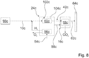
- FIGS. 7 and 8th further embodiments not according to the invention are shown.
- the following descriptions are essentially limited to the differences between the exemplary embodiments, reference being made to the description of the first exemplary embodiment with regard to components, features and functions that remain the same.
- the letters a, b and c are added to the reference numerals.
- identically designated components in particular with regard to components having the same reference numerals, it is also possible in principle to refer to the drawings and / or the description of the first exemplary embodiment in FIGS FIGS. 1 to 6 to get expelled.
- FIGS. 7 and 8th two further simplified process illustrations are shown, in which an absorption process 18b, 18c is used in unspecified absorption units for gas treatment, in particular for fine cleaning of a generated methane 62a, 62b of a power-to-gas plant 24b, 24c, whereby before feeding into a Natural gas network 64b, 64c a very high purity of methane 62b, 62c is achieved.
- the absorption units in the FIGS. 7 and 8th are corresponding to the absorption units 22a, 22a ', 22a ", 22a'" of the embodiment in the FIGS. 1 to 6 educated.
- the process in FIG. 7 shows a process in which the gas treatment is carried out in a biogas plant 98b with a membrane process 14b and the process in FIG. 8 shows a process by the gas treatment is performed in a biogas plant 98c without membrane process.
- a CO 2 or permeate 46b separated from the membrane process 14b is supplied to the power-to-gas plant 24b and the permeate 46b is converted into methane and water together with H 2 in a methanation 60b in a process step 102b in a reactive process 104b.
- the product gas after methanation 60b has purities greater than 90% by volume of methane.
- a gas fine cleaning is then carried out in an absorption process 18b in the absorption units, not shown, whereby the unreacted CO 2 is separated and the product gas is additionally dried.
- the separated CO 2 is preferably returned to the methanation 60b as a pure CO 2 or CO 2 / H 2 gas mixture.
- the CO 2 contained in the biogas 10 c is converted in a process step 102 c in a reactive process 104 c by a catalytic reaction with H 2 in a methanation unit 60 c. Subsequently, a gas fine cleaning of the product gas in a subsequent process step 16c in a Absorption process 18c in absorption units in an analogous manner as in the process in FIG. 7 carried out. Before the biogas 10c is supplied to the power-to-gas plant 24c, the biogas 10c is dried and pre-cleaned, in particular desulphurised.
Landscapes
- Chemical & Material Sciences (AREA)
- Engineering & Computer Science (AREA)
- Oil, Petroleum & Natural Gas (AREA)
- Organic Chemistry (AREA)
- Chemical Kinetics & Catalysis (AREA)
- General Chemical & Material Sciences (AREA)
- Analytical Chemistry (AREA)
- Life Sciences & Earth Sciences (AREA)
- Water Supply & Treatment (AREA)
- Health & Medical Sciences (AREA)
- Wood Science & Technology (AREA)
- Bioinformatics & Cheminformatics (AREA)
- Zoology (AREA)
- Biotechnology (AREA)
- Microbiology (AREA)
- Sustainable Development (AREA)
- Biomedical Technology (AREA)
- Biochemistry (AREA)
- General Engineering & Computer Science (AREA)
- General Health & Medical Sciences (AREA)
- Genetics & Genomics (AREA)
- Separation Using Semi-Permeable Membranes (AREA)
- Gas Separation By Absorption (AREA)
Description
- Aus der
EP 2 438 975 A1 sind bereits ein Verfahren und eine Vorrichtung bekannt, die einen Adsorber aus einem Adsorberharz aufweisen. In einer Adsorptionsphase wird Rohbiogas bei Umgebungsdruck durch den Adsorber geleitet. In einer Regenerationsphase wird der Adsorber mit einem Spülgas bei Temperaturen zwischen 20 - 100°C regeneriert. - Ferner sind aus der
DE 10 2011 103 430 A1 , derEP 2 682 450 A2 und derEP 2 532 729 A2 ebenfalls Verfahren zu einer Gasaufbereitung bekannt. - Eine Aufgabe der Erfindung besteht insbesondere darin, ein Verfahren mit einem hohen Wirkungsgrad bereitzustellen und/oder ein Verfahren, welches eine kompakte Vorrichtung ermöglicht. Die Aufgabe wird erfindungsgemäß durch die Merkmale des Patentanspruchs 1 gelöst, während vorteilhafte Ausgestaltungen und Weiterbildungen der Erfindung den Unteransprüchen und einem Nebenanspruch entnommen werden können.
- Es wird ein Verfahren zu einer Aufbereitung von Biogas einer Biogasanlage vorgeschlagen, bei dem in einem Verfahrensschritt zu einer CO2-Abtrennung aus dem Biogas ein Membranprozess in einer Membraneinheit durchgeführt wird und in einem weiteren, nachgeschalteten Verfahrensschritt ein Adsorptions- und/oder Absorptionsprozess in Absorptionseinheiten, zur Gasreinigung zur Erzielung einer Methanreinheit von größer als 99,5 Vol.% durchgeführt wird, wobei der Adsorptions- und/oder Absorptionsprozess als Nachreinigung durchgeführt wird, wobei in dem Adsorptions- und/oder Absorptionsprozess ein Festkörperadsorber und/oder ein Festkörperabsorber genutzt wird, und zwar ein Festamin, wobei in einem weiteren Verfahrensschritt ein reaktiver Prozess, bei dem in einer Power-to-Gas Anlage in einem katalytisch aktivierten chemischen Prozess ein methanreiches Gasgemisch erzeugt wird, durchgeführt wird, wobei bei der Power-to-Gas Anlage elektrische Energie aus einer Anlage, wie insbesondere einer Windkraftanlage und/oder einer Solaranlage, verwendet wird, um mittels Elektrolyse Wasserstoff zu erzeugen, wobei in der Power-to-Gas Anlage erzeugter Wasserstoff während der Regeneration der Adsorptions- und/oder Absorptionseinheit zugeführt wird und wobei die Adsorptions- und/oder Absorptionseinheit eine Funktion einer CO2-Speicherung und einer Gasvormischung für eine sich anschließende Methanisierung in der Power-to-Gas Anlage übernehmen, wobei der Wasserstoff während Regenerationsphasen der Absorptionseinheiten in die Absorptionseinheiten bei erhöhtem Druck eingeleitet wird und ein in den Absorptionseinheiten befindliches Absorptionsmaterial unter der H2-Atmosphäre thermisch regeneriert wird, wobei eine Abwärme der Power-to-Gas Anlage, und zwar von der Elektrolyse, die von einem Elektrolyseur durchgeführt wird, oder von einer Methanisierung, zur Regeneration des Absorptionsmaterials verwendet wird, wobei ein frei werdendes CO2/H2 Gasgemisch dann unter Druck einer sich anschließenden Methanisierung in der Power-to-Gas Anlage zugeführt wird. Darunter, dass der Adsorptions- und/oder Absorptionsprozess in einem "weiteren Verfahrensschritt" durchgeführt wird, soll in diesem Zusammenhang insbesondere verstanden werden, dass ein Adsorptions- und/oder Absorptionsmaterial getrennt, insbesondere beabstandet, insbesondere mit einem Abstand größer als 1 cm, von einer Membran angeordnet ist und/oder dass die Verfahrensschritte auch getrennt unabhängig voneinander betreibbar sind. Unter einem "reaktiven Prozess" soll in diesem Zusammenhang insbesondere ein Prozess verstanden werden, bei dem insbesondere in einem katalytisch aktivierten chemischen Prozess oder in einem biologischen Prozess, insbesondere mit einem Nährsubstrat, ein Gasgemisch erzeugt wird, wie insbesondere ein zumindest methanreiches Gasgemisch. Ganz besonders bevorzugt wird in dem reaktiven Prozess in einer Power-to-Gas Anlage zumindest ein methanreiches Gasgemisch aus einer CO2-Quelle erzeugt. Dabei wird vorzugsweise Biogas als CO2-Quelle genutzt. Unter einer "Power-to-Gas Anlage" soll dabei insbesondere eine Anlage verstanden werden, bei der elektrische Energie aus einer Anlage, wie insbesondere einer Windkraftanlage und/oder einer Solaranlage, verwendet wird, um mittels Elektrolyse Wasserstoff zu erzeugen. Dieser Wasserstoff wird dann insbesondere verwendet, um zusammen mit Kohlendioxid, wie insbesondere aus einer Biogasanlage oder aus einer anderen CO2-Quelle, mittels eines Katalysators Methan zu erzeugen. Das Methan kann, insbesondere nach einer CO2-Gasfeinreinigung mit der Adsorptions- und/oder Absorptionseinheit sowie einer Methantrocknung, in ein Erdgasnetz eingespeist werden. Die Adsorptions- und/oder Absorptionseinheit übernimmt neben der CO2-Gasfeinreinigung vorzugsweise ebenfalls die Funktion der Methanresttrocknung auf sehr niedrige Taupunkttemperaturen im Produktgas Methan.
- Es kann bei der Kombination der Verfahrensschritte eines Membranprozesses und eines Adorptions- und/oder Absorptionsprozesses eine Einsparung einer Membranstufe einer insbesondere mehrstufigen Membrananlage und damit eine erhebliche Membrananlagenverkleinerung erreicht werden, und zwar vorzugsweise um mehr als ein Drittel. Ferner kann eine besonders einfache Membranmodulverschaltung erreicht werden, und es können besonders hohe Gasqualitäten, insbesondere Bioerdgasqualitäten, mit einer Methanreinheit von größer als 99,5 Vol.%, erreicht werden, und zwar insbesondere, wenn der Adsorptions- und/oder Absorptionsprozess als Nachreinigung durchgeführt wird, wobei der Adsorptions- und/oder Absorptionsprozess insbesondere als Feinreinigung durchgeführt wird, bei der vorzugsweise eine Abreicherung von einer Kohlendioxidkonzentration im Prozessgas auf kleiner als 0,3 Vol.- % CO2 durchgeführt wird. Der Adsorptions- und/oder Absorptionsprozess kann dabei verwendet werden, um das Retentat und/oder das Permeat eines Membranmoduls aufzubereiten, d.h. mit entsprechenden hohen oder niedrigen Drücken. Zudem ist eine Absenkung eines Feeddrucks der Membrananlage möglich und damit eine Reduzierung von Anlagenbetriebskosten. Ferner ist eine Verkleinerung eines Wärmetauschers der Membrananlage möglich, der für eine Feedgas-Kühlung benötigt wird. Unter "Bioerdgas" soll in diesem Zusammenhang insbesondere Methan verstanden werden, das nicht fossilen Ursprungs ist, sondern aus biogenen Stoffen erzeugt wurde.
- Es kann bei der Kombination der Verfahrensschritte eines reaktiven Prozesses und eines Adsorptions- und/oder Absorptionsprozesses eine besonders hohe Gasqualität, insbesondere Bioerdgasqualitäten mit einer Methanreinheit von größer als 99,5 Vol.%, erreicht werden, und zwar insbesondere, wenn der reaktive Prozess als katalytischer Methanisierungsprozess ausgeführt wird und das im Bioerdgas enthaltene CO2 mit H2 aus einer Power-to-Gas Anlage katalytisch zu Methan und Wasser umgesetzt wird und anschließend ein Adsorptions- und/oder Absorptionsprozess als Nachreinigung durchgeführt wird, wobei der Adsorptions- und/oder Absorptionsprozess insbesondere als Feinreinigung durchgeführt wird, bei der vorzugsweise eine Abreicherung von einer Kohlendioxidkonzentration im Prozessgas auf kleiner als 0,3 Vol.-% CO2 durchgeführt wird. Es können jedoch auch ein Verfahrensschritt mit einem Membranprozess, ein Verfahrensschritt mit einem reaktiven Prozess und ein Verfahrensschritt mit einem Adsorptions- und/oder Absorptionsprozess in verschiedenen, dem Fachmann als sinnvoll erscheinenden Varianten kombiniert werden.
- Grundsätzlich sind verschiedene, dem Fachmann als sinnvoll erscheinende Adsorber- und/oder Absorbermaterialien denkbar, wie insbesondere flüssige oder gasförmige Adsorber- und/oder Absorbermaterialien. Besonders vorteilhaft wird jedoch zumindest ein Festkörperadsorber und/oder ein Festkörperabsorber genutzt, und zwar ganz besonders bevorzugt ein Absorber- und/oder Adsorberharz. Besonders eignet sich ein Amin, und zwar bevorzugt ein Festamin. Das Absorptions- und/oder Adsorptionsmaterial weist dabei vorzugsweise eine Selektivität bei Standardbedingungen, d.h. bei einer Temperatur von 25°C und einem Druck von 1 barabs, größer als 100, besonders bevorzugt größer als 150 und ganz bevorzugt größer als 200 auf. Unter einer "Selektivität" soll dabei ein Beladungsverhältnis, insbesondere ein Festamin-Beladungsverhältnis verstanden werden, insbesondere ein Beladungsverhältnis zwischen CO2 und CH4. Das Absorptions- und/oder Adsorptionsmaterial wird vorzugsweise in Form einer Schüttung verwendet. Unter einer "Schüttung" soll in diesem Zusammenhang insbesondere verstanden werden, dass das Material in einem körnigen und/oder auch stückigen Gemenge vorliegt, das in einer schüttfähigen Form vorliegt. Mit einem Festamin können vorteilhaft niedrige Regenerationstemperaturen erreicht werden, wodurch besonders vorteilhaft Abwärme von anderen Einheiten, wie insbesondere eines Blockheizkraftwerks (BHKWs), einer Membraneinheit und/oder einer Power-to-Gas Anlage genutzt werden kann. Ferner können eine hohe Lebensdauer und eine besonders hohe Gasreinheit erzielt werden. Alternativ zu einem Amin sind jedoch auch grundsätzlich Molekularsiebe, beispielsweise aus Aktivkohle usw., denkbar.
- In einer weiteren Ausgestaltung der Erfindung wird vorgeschlagen, dass zumindest eine Adsorptions- und/oder Absorptionseinheit in zumindest einem Verfahrensschritt gekühlt oder erwärmt wird, wodurch der Adsorptions- und/oder Absorptionsprozess und/oder ein Regenerationsprozess besonders vorteilhaft unterstützt werden kann. Unter "gekühlt" oder "erwärmt" soll dabei insbesondere verstanden werden, dass aktiv, insbesondere mit einer dritten Einheit, Wärme abgeführt oder Wärme zugeführt wird. Vorzugsweise wird eine sogenannte Temperatur Swing Adsorption- und/oder Absorption durchgeführt, bei der bei einer niedrigen Temperatur eine Adsorption und/oder Absorption durchgeführt wird und bei einer höheren Temperatur eine Regeneration durchgeführt wird. Die Adsorption und/oder Absorption findet dabei vorteilhaft bei einer Temperatur kleiner als 40°C, vorzugsweise kleiner als 30°C und ganz besonders bevorzugt kleiner als 20°C statt, während die Regeneration vorteilhaft bei einer Temperatur größer als 70°, vorzugsweise bei einer Temperatur größer als 80°C und ganz besonders bevorzugt größer als 90°C durchgeführt wird. Vorzugsweise wird die Regeneration jedoch bei einer Temperatur kleiner als 120°C durchgeführt.
- Vorzugsweise wird zu Beginn der Regeneration der Adsorptions- und/oder Absorptionseinheit eine Methanrückgewinnung mittels einer Vakuumpumpe realisiert.
- Wird Wärmeenergie von zumindest einer Adsorptions- und/oder Absorptionseinheit zu zumindest einer weiteren Adsorptions- und/oder Absorptionseinheit übertragen und/oder wird Druckenergie von zumindest einer Adsorptions- und/oder Absorptionseinheit zu zumindest einer weiteren Adsorptions- und/oder Absorptionseinheit übertragen, kann durch eine vorteilhafte Wärmeintegration bzw. Druckintegration Energie eingespart und ein hoher Wirkungsgrad erreicht werden. Vorzugsweise sind dabei mehrere Adsorptions- und/oder Absorptionseinheiten miteinander verschaltet. Vorzugsweise werden die Adsorptions- und/oder Absorptionseinheiten im Wechsel gegenseitig bedruckt oder evakuiert. Es wird vorteilhaft eine sogenannte Pressure Swing Adsorption- und/oder Absorption durchgeführt, bei der bei einem höheren Druck eine Adsorption und/oder Absorption durchgeführt wird und bei einem niedrigeren Druck eine Regeneration durchgeführt wird.
- Ferner wird vorgeschlagen, dass zu einer Temperierung, d.h. Kühlung und/oder Erwärmung, einer Adsorptions- und/oder Absorptionseinheit Abwärme genutzt wird, und zwar insbesondere Abwärme eines Kraftwerks, insbesondere eines Blockheizkraftwerks, und/oder Abwärme des Membranprozesses und/oder ganz besonders bevorzugt von einer Power-to-Gas Anlage, wodurch wiederum Energie eingespart werden kann. Bei einer Power-to-Gas Anlage kann die Abwärme bevorzugt eines Elektrolyseurs und/oder freiwerdende Reaktionswärme der katalytischen Methanisierung zu einer Regeneration eines Adsorber- und Absorbermaterials genutzt werden. Insbesondere kann zu einer Kühlung im Adsorptions- und/oder Absorptionsprozess eine Kälteanlage verwendet werden, welche Abwärme zur Kälteerzeugung verwendet. Besonders vorteilhaft sind mehrere Adsorptions- und/oder Absorptionseinheiten miteinander verschaltet und eine Wärmeintegration der Adsorptions- und/oder Absorptionseinheiten wird mittels eines umgewälzten Wärmeträgerfluids untereinander und/oder im Verbund mit einem Blockheizkraftwerk und/oder mit einer Membraneinheit und/oder mit der Power-to-Gas Anlage realisiert. Eine anfallende Adsorptions- und/oder Absorptionswärme während der CO2-Adsorption und/oder Absorption kann vorteilhaft der Biogasanlage zugeführt werden. Bei der Methanerzeugung (Methanisierung) in einer Power-to-Gas Anlage wird durch die exotherme Reaktion CO2+4H2 ↔ CH4 + 2H2O Wärme frei, die vorzugsweise in der Biogasanlage und/oder vorteilhaft in einem entsprechenden erfindungsgemäßen Verfahren, insbesondere zur Regeneration der Adsorptions- und/oder Absorptionseinheit genutzt werden kann.
- Erfindungsgemäß wird vorgeschlagen, dass zumindest einer Adsorptions- und/oder Absorptionseinheit Wasserstoff zugeführt wird, und zwar insbesondere von einer Power-to-Gas Anlage. Der Wasserstoff wird dabei vorzugsweise während einer Regeneration in die Adsorptions- und/oder Absorptionseinheit eingeleitet, wodurch die Regeneration besonders effizient durchgeführt werden kann, und zwar insbesondere aufgrund einer erzielbaren verbesserten Wärmeleitfähigkeit eines Adsorptions-und/oder Absorptionsmaterials unter einer H2-Atmosphäre, und zwar vorzugsweise aufgrund einer verbesserten Wärmeleitfähigkeit einer Adsorptions- und/oder Absorptionsharzschüttung. Die Regeneration findet vorzugsweise bei erhöhtem
Druck, d.h. insbesondere bei einem Druck größer als 2 barabs. und besonders vorteilhaft größer als 4 barabs. und unter einer H2-Atmosphäre statt. Die Edukte H2 und CO2 werden vorzugsweise bei einem so hohen Druckniveau am Ende einer Desorption an die Power-to-Gas Anlage abgegeben, dass in einer anschließenden Methanisierung das Produktgas Methan ohne Nachverdichtung direkt ins Erdgasnetz eingespeist werden kann. Hierdurch kann energetisch besonders günstig eine Druckerhöhung vor einer Elektrolyse innerhalb der Power-to-Gas Anlage erreicht werden. Eine Regeneration ohne Wasserstoffzufuhr in die Adsorptions- und/oder Absorptionseinheit findet vorzugsweise bei einem Druck kleiner als 1,5 barabs. statt. - Die Adsorptions- und/oder Absorptionseinheit und insbesondere eine darin befindliche Adsorptions- und/oder Absorptionsharzschüttung kann vorteilhaft eine Funktion einer CO2-Speicherung und einer Gasvormischung für eine sich anschließende Methanisierung in der Power-to-Gas Anlage übernehmen. Ferner können die Edukte CO2 und H2 für die Methanisierung bei erhöhtem Druck gewonnen werden, was sich günstig auf eine Gleichgewichtslage und einen erzielbaren Umsatz der Methanisierung auswirkt. Die Regeneration der Adsorptions- und/oder Absorptionseinheit und insbesondere die Regeneration einer Adsorptions- und/oder Absorptionsharzschüttung unter einer Wasserstoffatmosphäre, wird über die Wasserstoffzufuhr sowie einen Regenerationsdruck und eine Temperatur vorteilhaft so geregelt, dass die Edukte CO2 und H2 für eine sich anschließende Methanisierung in der Power-to-Gas Anlage zumindest im Wesentlichen im stöchiometrischen Verhältnis aus der Adsorptions- und/oder Absorptionseinheit abgeführt werden können. Unter zumindest im Wesentlichen soll dabei insbesondere verstanden werden, dass eine Abweichung kleiner als 20% und besonders bevorzugt kleiner als 10% vorliegt.
- Ferner wird in Anspruch 5 eine Vorrichtung zu einer Durchführung eines erfindungsgemäßen Verfahrens vorgeschlagen.
- Vorzugsweise umfasst die Vorrichtung zumindest eine Heiz- und/oder Kühleinheit, wodurch, wie oben beschrieben, vorteilhaft eine aktive Erwärmung und/oder aktive Kühlung durchgeführt werden kann.
- Umfasst die Heiz- und/oder Kühleinheit zumindest einen Wärmetauscher, kann eine besonders effektive Wärmeübertragung erreicht werden, und zwar insbesondere, wenn in den Wärmetauscher wenigstens ein Adsorptions- und/oder Absorptionselement integriert ist. Dabei soll unter "integriert" insbesondere verstanden werden, dass Teile des Wärmetauschers mit einem Adsorptions- und/oder Absorptionsmaterial befüllt und/oder beschichtet sind. Besonders vorteilhaft umfasst der Wärmetauscher wenigstens ein Rohr, welches zumindest teilweise mit einem Adsorptions- und/oder Absorptionsmaterial gefüllt ist, und zwar besonders vorteilhaft mit einem Harz und ganz besonders bevorzugt mit einer Harzschüttung, insbesondere einer Festamin-Harzschüttung. Das Biogas wird dabei vorzugsweise durch das Adsorptions- und/oder Absorptionsmaterial, insbesondere durch die Harzschüttung in dem Rohr, geleitet. In einem Mantelraum des Wärmetauschers, der vorzugsweise als Rohrbündelwärmetauscher ausgebildet sein kann, wird dann vorzugsweise ein Wärmeträgerfluid geführt.
- In einer weiteren Ausgestaltung wird vorgeschlagen, dass das wenigstens eine Rohr zumindest eine erste und eine zweite Wandung aufweist und das Adsorptions- und/oder Absorptionsmaterial zumindest teilweise zwischen den Wandungen angeordnet ist, wodurch das Adsorptions- und/oder Absorptionsmaterial vorteilhaft von innen und von außen beheizbar ist. Alternativ kann das Rohr jedoch auch nur eine Wandung aufweisen.
- Weitere Vorteile ergeben sich aus der folgenden Zeichnungsbeschreibung. In den Zeichnungen ist ein Ausführungsbeispiel der Erfindung dargestellt. Die Zeichnungen, die Beschreibung und die Ansprüche enthalten zahlreiche Merkmale in Kombination. Der Fachmann wird die Merkmale zweckmäßigerweise auch einzeln betrachten und zu sinnvollen weiteren Kombinationen zusammenfassen.
- Es zeigen:
- Fig. 1
- eine vereinfachte Prozessdarstellung mit einer Membraneinheit,
- Fig. 2
- einen schematisch dargestellten Ausschnitt einer erfindungsgemäßen Vorrichtung mit einer Absorptionseinheit,
- Fig. 3
- einen schematisch dargestellten Ausschnitt einer Schnittdarstellung durch die Absorptionseinheit aus
Fig. 2 , - Fig. 4
- einen schematisch dargestellten Ausschnitt einer Schnittdarstellung einer zu der in
Figur 2 dargestellten alternativen Absorptionseinheit, - Fig. 5
- vereinfacht dargestellte Prozessabläufe bei mehreren verschalteten Absorptionseinheiten und
- Fig. 6
- eine vereinfachte Darstellung eines Fließbilds der Vorrichtung,
- Fig. 7
- eine nicht erfindungsgemäße weitere vereinfachte Prozessdarstellung mit einer Membraneinheit und einer Power-to-Gas Anlage und
- Fig. 8
- eine nicht erfindungsgemäße weiter vereinfachte Prozessdarstellung mit einer Power-to-Gas Anlage und ohne Membraneinheit.
-
Figur 1 zeigt eine vereinfachte Prozessdarstellung bzw. eine vereinfachte Darstellung eines erfindungsgemäßen Verfahrens zu einer Gasaufbereitung, und zwar zu einer Aufbereitung von Biogas 10a in einer Biogasanlage 98a, bei dem in einem Verfahrensschritt 12a zu einer CO2-Abtrennung aus dem Biogas 10a ein Membranprozess 14a in einer Membraneinheit 26a durchgeführt wird und in einem weiteren, nachgeschalteten Verfahrensschritt 16a ein Absorptionsprozess 18a in Absorptionseinheiten 22a, 22a', 22a", 22a'" durchgeführt wird (vgl.Figuren 1 ,2 und6 ). In der Membraneinheit 26a werden nicht näher dargestellte Hohlfasermembrane eingesetzt, wobei grundsätzlich auch andere, dem Fachmann als sinnvoll erscheinende Membrane denkbar sind. Das Biogas 10a wird mittels eines Kompressors 66a der Membraneinheit 26a zugeführt, und zwar wird das Biogas 10a durch die Hohlfasermembrane gepumpt. Der Membranprozess 14a, welcher mittels einer Rückführung 96a mehrstufig ausgebildet ist, wird als Vorreinigung, insbesondere zu einer Abreicherung einer CO2-Konzentration im Biogas 10a von ca. 45 Vol.-% auf 3 - 5 Vol.-% CO2, vor dem Absorptionsprozess 18a durchgeführt. Der Absorptionsprozess 18a übernimmt im Anschluss eine Nachreinigung, und zwar insbesondere eine Feinreinigung, mit vorzugsweise einer Anreicherung eines Bioerdgases 52a auf eine Methankonzentration größer als 99%. Ein Retentat 44a der Membraneinheit 26a wird mittels des Kompressors 66a den Absorptionseinheiten 22a, 22a, 22a", 22a'" zur Feinreinigung zugeführt. Grundsätzlich könnten jedoch auch die Absorptionseinheiten 22a, 22a', 22a", 22a'" zusätzlich oder alternativ zu einer Aufbereitung eines Permeats 46a der Membraneinheit 26a eingesetzt werden. Das Permeat 46a besteht dabei nahezu vollständig aus CO2 und einem Anteil CH4 bzw. Methan kleiner 0,5 Vol.-%. Ein erfindungsgemäßer Gesamtprozess nutzt vorteilhaft unterschiedliche Selektivitäten der Membraneinheit 26a und der Absorptionseinheiten 22a, 22a', 22a", 22a'" zu einer CO2/CH4-Gastrennung aus. - Das Verfahren kann grundsätzlich allein gemeinsam mit einer Biogasanlage 98a betrieben werden oder kann vorteilhaft bei einer Kombination einer Biogasanlage 98a mit weiteren, dem Fachmann als sinnvoll erscheinenden Anlagen betrieben werden, wie insbesondere besonders vorteilhaft in Kombination mit einer Power-to-Gas Anlage 24a. Hierzu weist die erfindungsgemäße Vorrichtung einen Anlagenanschluss 42a zum Anschluss einer reaktiven Anlage, und zwar zum Anschluss der Power-to-Gas Anlage 24a auf. Die Power-to-Gas Anlage 24a, der Wasser mittels einer Wasserpumpe 80a zugeführt wird, nutzt Strom 54a, wie vorzugsweise aus Anlagen, die aus erneuerbaren Energiequellen Strom gewinnen, wie insbesondere Windkraftanlagen, Solaranlagen usw., um damit mittels einer Elektrolyse 56a H2 und O2 bei erhöhtem Druck, vorzugsweise bei einem Druck höher als 5 barabs, insbesondere bei einem Druck von zumindest im Wesentlichen 10 barabs. zu erzeugen. Unter zumindest im Wesentlichen soll dabei insbesondere verstanden werden, dass eine Abweichung kleiner als 20% und besonders bevorzugt kleiner als 10% vorliegt.
- Die Power-to-Gas Anlage 24a wird vorzugsweise mit einer konstanten Strommenge versorgt, um eine hohe Lebensdauer zu erzielen. Die Power-to-Gas Anlage 24a kann hierfür mit einer oder mehreren Anlagen gekoppelt sein. Grundsätzlich ist auch denkbar, dass bei der Power-to-Gas Anlage 24a Überschussenergie einer Anlage genutzt wird. In der Power-to-Gas Anlage 24a wird in einem Verfahrensschritt 102a in einem reaktiven Prozess 104a Methan 62a erzeugt.
- Der Wasserstoff wird während Regenerationsphasen der Absorptionseinheiten 22a, 22a', 22a", 22a'" in die Absorptionseinheiten 22a, 22a', 22a", 22a'" bei erhöhtem Druck eingeleitet und ein in den Absorptionseinheiten 22a, 22a', 22a", 22a'" befindliches Absorptionsmaterial wird unter H2-Atmosphäre thermisch regeneriert. Eine Abwärme 58a der Power-to-Gas Anlage 24a, und zwar von der Elektrolyse 56a, die von einem Elektrolyseur durchgeführt wird, und von einer Methanisierung 60a, wird zur Regeneration des Absorptionsmaterials verwendet. Ein frei werdendes CO2/H2 Gasgemisch wird dann unter Druck, vorzugsweise zumindest im Wesentlichen bei 10 barabs. und nahe bzw. zumindest im Wesentlichen bei einem stöchiometrischen Verhältnis ¼, einer sich anschließenden Methanisierung 60a in der Power-to-Gas Anlage 24a zugeführt. Die Methanisierung 60a erfolgt bevorzugt bei einem Druckniveau, sodass keine Nachverdichtung des sich aus der Methanisierung 60a ergebenden Methans 62a zur Einspeisung in ein Erdgasnetz 64a benötigt wird. Vor der Einspeisung in das Erdgasnetz 64a wird das Methan 62a getrocknet.
- Die
Figur 2 zeigt einen schematisch dargestellten Ausschnitt einer erfindungsgemäßen Vorrichtung zur Durchführung des Verfahrens. Die Vorrichtung umfasst die Membraneinheit 26a und die Absorptionseinheiten 22a, 22a', 22a", 22a'" sowie Heiz- und Kühleinheiten 28a, 30a, 32a (Figuren 2 und6 ). - Im Absorptionsprozess 18a wird ein Festkörperabsorber 20a genutzt, und zwar ein Festamin. Das Festamin ist in heiz- und kühlbare Apparate integriert, und zwar in Wärmetauscher der Heiz- und Kühleinheiten 32a, 32a', 32a", 32a"', somit sind Absorptionselemente in den Wärmetauschern integriert (
Figuren 2 ,3 ,4 und6 ). Die Absorptionseinheiten 22a, 22a', 22a", 22a'" weisen dabei eine Bauform auf, die vergleichbar ist, mit der eines Rohrbündelwärmetauschers. Das Festamin ist in Rohre 34a in Form einer Schüttung eingefüllt (Figuren 2 ,3 und 4 ). Ein Wärmeträgerfluid 48a wird mantelseitig durch die Wärmetauscher geleitet. Die Rohre 34a sind druckstabil ausgeführt und bestehen aus Metall, vorzugsweise aus Edelstahl. Ein äußeres Gehäuse 50a der Wärmetauscher bzw. der Absorptionseinheiten 22a, 22a', 22a", 22a'" muss nicht druckstabil sein und ist aus einem Kunststoffmaterial gefertigt. Grundsätzlich sind jedoch sowohl für die Rohre 34a als auch für das Gehäuse 50a andere, dem Fachmann als sinnvoll erscheinende Materialien denkbar. Alternativ zu den Rohren 34a, die einwandig ausgebildet sind, könnten die Absorptionseinheiten 22a, 22a', 22a", 22a'" auch Rohre 36a aufweisen, die eine erste und eine zweite Wandung 38a, 40a aufweisen, wobei das Festamin in einer Ringspalte zwischen den Wandungen 38a, 40a angeordnet ist (Fig. 4 ). Die Rohre 34a werden im Betrieb mantelseitig von dem Wärmeträgerfluid 48a umströmt, während die Rohre 36a im Betrieb mantelseitig und im Inneren von dem Wärmeträgerfluid 48a umströmt werden. Ein Design mit den Rohren 36a verspricht eine besonders effiziente und schnelle Regeneration der Absorptionseinheiten 22a, 22a', 22a", 22a'" bzw. eines Absorptionsharzes. Ein Design mit den Rohren 34a kann besonders einfach gefertigt werden. - Prozessgas bzw. das Retentat 44a aus der Membraneinheit 26a wird in den Rohren 34a durch das Festamin, das in Form einer Schüttung vorliegt, geleitet. Dabei wird das CO2 hochselektiv am Festamin während des Absorptionsprozesses 18a gebunden und Bioerdgas 52a kann an Ausgängen 78a der Absorptionseinheiten 22a, 22a', 22a", 22a'" gewonnen und in das Erdgasnetz 64a eingespeist werden.
- Die Absorptionseinheiten 22a, 22a', 22a", 22a'" weisen jeweils mehrere Ventile V1, V2, V9 - V13 auf einer Gasseite sowie mehrere Ventile V3 - V8 auf einer Wärmeträgerfluidseite auf (
Fig. 2 ). An den Ventilen V1, V2, V9 - V13 und V3 - V8 sind jeweils Rohranschlüsse vorgesehen. - Die Ventile V1, V2, V9, V10, V11, V13 auf der Gasseite werden benötigt, um einen PSA (Pressure Swing Absorption) Prozess realisieren zu können. Die Absorption des CO2 am Festamin erfolgt dabei bei einem hohen Druck, vorzugsweise bei einem Druck zwischen 4 barabs. und 20 barabs. Die Regeneration erfolgt bei einem Gesamtprozess ohne Power-to-Gas Anlage 24a bei einem niedrigen Druck, und zwar vorzugsweise bei einem Druck zwischen 0,1 barabs. und 1,5 barabs. Bei einem Gesamtprozess mit der Power-to-Gas Anlage 24a erfolgt die Regeneration bei einem erhöhten Druck, und zwar vorzugsweise bei einem Druck zwischen 4 barabs. und 20 barabs. Es wird dabei H2 während der Regeneration in die Rohre 34a der Absorptionseinheiten 22a, 22a', 22a", 22a'" mittels eines Ventils V13 eingeleitet und die Regeneration des Festamins wird unter Wasserstoffatmosphäre bei erhöhtem Druck durchgeführt. Die Wasserstoffzufuhr sowie die Regenerationstemperatur in den Rohren 34a wird dabei so geregelt, dass sich ein molares Mischungsverhältnis in der Gasphase von RH2/CO2 = 4 +/- 20 % einstellt.
- Die Ventile V9 - V12 werden dazu benötigt, eine Methanrückgewinnung über einen Anschluss 72a mit einer Vakuumpumpe 68a am Ende einer Absorptionsphase und vor Beginn der Regeneration des Festamins zu realisieren und Methan 62a aus einer freien Gasphase der Harzschüttung abzusaugen und dieses zum Kompressor 66a zurückzuführen oder der Power-to-Gas Anlage 24a über den Power-to-Gas Anlagenanschluss 42a zuzuführen (
Figuren 1 und2 ). Die Ventile V9 - V12 werden auch dazu benötigt, CO2 aus den Absorptionseinheiten 22a, 22a', 22a", 22a'" während Regenerationsphasen abzusaugen, und zwar im Falle eines Betriebs ohne Power-to-Gas Anlage 24a. Ferner werden die Ventile V9 - V12 dazu benötigt, Absorptionseinheiten 22a, 22a', 22a", 22a'" beim PSA Prozess miteinander zu verschalten und die Absorptionseinheiten 22a, 22a', 22a", 22a'" im Wechsel zu befüllen oder zu entleeren und damit Betriebszeiten der Vakuumpumpe 68a und damit verbundene Betriebskosten zu minimieren. Zwischen den Ventilen V9 und V11 ist ein Anschluss 70a zu einer weiteren Absorptionseinheit 22a', 22a", 22a'" vorgesehen. - Die Ventile V3 - V8 auf der Wärmeträgerfluidseite werden benötigt, um einen TSA (Temperature Swing Absorption) Prozess realisieren zu können. Die Ventile V3 - V5 sind dabei mit einem Wärmeträgerfluidausgang 74a und die Ventile V6 - V8 sind mit einem Wärmeträgerfluideingang 76a verschaltet. Die Absorption des CO2 am Festamin erfolgt dabei bei niedriger Temperatur und die Regeneration bei hoher Temperatur (max. 110°C). Dabei wird eine anfallende Absorptionswärme 82a während der CO2-Absorption am Festamin über den Wärmeträgerfluidausgang 74a der Biogasanlage 98a zugeführt, wodurch die Absorptionseinheiten 22a 22a', 22a", 22a'" bzw. Festaminschüttungen gekühlt werden. Ferner sind die Absorptionseinheiten 22a, 22a', 22a", 22a'" über die Ventile V4 - V7 miteinander verschaltet, um eine Wärmeintegration der Absorptionseinheiten 22a, 22a', 22a", 22a'" untereinander sowie gegebenenfalls mit einem Blockheizkraftwerk, der Membraneinheit 26a und/oder Power-to-Gas Anlage 24a zu realisieren. Ferner können die Ventile V3 - V8 zur Aufheizung und zur Kühlung der Absorptionseinheiten 22a, 22a', 22a", 22a'" während der Regeneration des Festamins genutzt werden.
- Die Absorptionseinheiten 22a, 22a', 22a", 22a'" weisen jeweils an ihrem Ausgang 78a einen CO2-Sensor S1, S1', S1", S1'" auf, mit dem eine CO2-Konzentration im Bioerdgas 52a gemessen und über den die Prozessabläufe Absorption und Regeneration der Absorptionseinheiten 22a, 22a', 22a", 22a'" zeitlich geregelt werden.
- Temperatursensoren T und Drucksensoren P an den Absorptionseinheiten 22a, 22a', 22a", 22a'" dienen zusätzlich zu einer zeitlichen Regelung der Prozessschritte während Absorptions- und Regenerationsphasen.
- Durch die mehreren Absorptionseinheiten 22a, 22a', 22a", 22a'" und eine Verschaltung derselben untereinander, kann ein quasikontinuierlicher Prozess erreicht werden, bei dem die Absorptionseinheiten 22a, 22a', 22a", 22a'" Absorptions- und Regenerationsphasen zeitversetzt durchlaufen (
Fig. 5 ). - Der Absorptionsprozess 18a mit dem CO2-Absorberharz umfasst eine Absorptionsphase AP als Feinreinigungsstufe, in der das CO2 am Absorptionsmaterial, und zwar am Festamin, bei einem Druck zwischen 1 barabs. und 15 barabs. gebunden und Absorptionswärme 82a gewonnen wird. Die Absorptionswärme 82a wird aus den Absorptionseinheiten 22a, 22a', 22a", 22a'" mittels des Wärmeträgerfluids 48a abgeführt, wodurch das Absorptionsmaterial mittels des Wärmeträgerfluids 48a gekühlt wird. Die Absorptionswärme 82a wird der Biogasanlage 98a, insbesondere einem Fermenter, zugeführt. Das Bioerdgas 52a kann während dieser Phase am Ausgang der Vorrichtung gewonnen und in das Erdgasnetz 64a eingespeist werden.
- Ferner umfasst der Absorptionsprozess 18a eine Regenerationsphase RP, in der das CO2 aus dem Absorptionsmaterial, und zwar aus dem Festamin, ausgetrieben wird, wobei sich die Regenerationsphase RP in weitere Phasen I - V aufgeteilt:
- I. Druckabsenkung/Evakuierung des Absorptionsmaterials und Methanrückgewinnung aus einem Leerraum der Absorptionseinheit 22a, 22a', 22a", 22a'".
Die Evakuierung findet dabei vorzugsweise isotherm statt. - II. Wasserstoffzufuhr aus der Power-to-Gas Anlage 24a (bevorzugt jedoch optional)
- III. Aufheizphase des Absorptionsmaterials mittels des Wärmeträgerfluids 48a, vorzugsweise auf eine Temperatur kleiner als 120°C. Hierbei kann Abwärme 84a eines BHKWs und/oder der Membraneinheit 26a und/oder der Power-to-Gas Anlage 24a und/oder einer der anderen Absorptionseinheiten 22a, 22a', 22a", 22a'" genutzt werden. Hierzu ist eine Heiz- und Kühleinheit 30a in Form eines Wärmetauschers vorgesehen (
Fig. 6 ). Eine CO2-Abfuhr findet dabei entweder unter Verwendung der Vakuumpumpe 68a (Prozess ohne Power-to-Gas Anlage 24a) und/oder unter Verwendung von H2 als Spülgas (Prozess mit Power-to-Gas Anlage 24a und direkter H2-Zufuhr) statt. Dabei wird das Spülgas vorzugsweise unter erhöhtem Druck zugeführt. In diesem Fall kann zumindest zeitweise auf einen Einsatz der Vakuumpumpe 68a oder auch vollständig auf die Vakuumpumpe 68a verzichtet werden. Für eine Zirkulation des Wärmeträgerfluids 48a sind zwei Pumpen 92a, 94a vorgesehen. - IV. Abkühlphase des Absorptionsmaterials mittels des Wärmeträgerfluids 48a und Wärmeintegration bzw. Realisierung des TSA Prozesses durch Übertragung einer Abwärme 86a an eine andere Absorptionseinheit 22a, 22a', 22a", 22a"', die sich in einer Aufheizphase III befindet. Eine Restabwärme 88a wird an die Biogasanlage 98a, und zwar vorzugsweise an den Fermenter, abgegeben.
- V. Befüllung/Bedruckung des Absorptionsmaterials mit Biogas 10a aus der Membraneinheit 26a.
- Zur Kühlung ist eine Kühleinheit 28a in Form einer Absorptionskälteanlage vorgesehen, wobei eine Restwärme-Kopplung mit der Biogasanlage 98a vorgenommen wird (
Fig. 6 ). - Wie zuvor ausgeführt, wird über die Ventile V1, V2, V9, V10, V11, V13 ein PSA Prozess bzw. ein Druckwechsel zwischen den Absorptionseinheiten 22a, 22a', 22a", 22a'" realisiert. Hierbei wird Druckenergie 90a von einer Absorptionseinheit 22a, 22a', 22a", 22a'" zu einer anderen Absorptionseinheit 22a, 22a', 22a", 22a'" übertragen, und zwar in der Weise, dass ein Druck zu Beginn der Absorptionsphase AP erhöht und ein Druck zu Beginn der Regenerationsphase RP reduziert wird. Im dargestellten Ausführungsbeispiel sind hierzu die Absorptionseinheit 22a und die Absorptionseinheit 22a" miteinander verschaltet und es sind die Absorptionseinheit 22a' und die Absorptionseinheit 22a'" miteinander verschaltet.
- Am Ausgang der Anlage sind ein Strömungssensor S2 und ein CH4-Sensor S3 angeordnet.
- In den
Figuren 7 und8 sind weitere nicht erfindungsgemäße Ausführungsbeispiele gezeigt. Die nachfolgenden Beschreibungen beschränken sich im Wesentlichen auf die Unterschiede zwischen den Ausführungsbeispielen, wobei bezüglich gleichbleibender Bauteile, Merkmale und Funktionen auf die Beschreibung des ersten Ausführungsbeispiels verwiesen werden kann. Zur Unterscheidung der Ausführungsbeispiele sind den Bezugszeichen die Buchstaben a, b und c hinzugefügt. Bezüglich gleich bezeichneter Bauteile, insbesondere in Bezug auf Bauteile mit gleichen Bezugszeichen, kann grundsätzlich auch auf die Zeichnungen und/oder die Beschreibung des ersten Ausführungsbeispiels in denFiguren 1 bis 6 verwiesen werden. - In den
Figuren 7 und8 sind zwei weitere vereinfachte Prozessdarstellungen gezeigt, in denen ein Absorptionsprozess 18b, 18c in nicht näher dargestellten Absorptionseinheiten zur Gasaufbereitung eingesetzt wird, insbesondere zur Feinreinigung eines erzeugten Methans 62a, 62b einer Power-to-Gas Anlage 24b, 24c, wodurch vor der Einspeisung in ein Erdgasnetz 64b, 64c eine sehr hohe Reinheit des Methans 62b, 62c erzielt wird. Die Absorptionseinheiten in denFiguren 7 und8 sind entsprechend den Absorptionseinheiten 22a, 22a', 22a", 22a'" des Ausführungsbeispiels in denFiguren 1 bis 6 ausgebildet. Der Prozess inFigur 7 zeigt dabei einen Prozess, indem die Gasaufbereitung in einer Biogasanlage 98b mit einem Membranprozess 14b durchgeführt wird und der Prozess inFigur 8 zeigt einen Prozess, indem die Gasaufbereitung in einer Biogasanlage 98c ohne Membranprozess ausgeführt ist. - Bei dem Prozess in
Figur 7 wird ein von dem Membranprozess 14b abgetrenntes CO2 bzw. Permeat 46b der Power-to-Gas Anlage 24b zugeführt und das Permeat 46b wird zusammen mit H2 in einer Methanisierung 60b in einem Verfahrensschritt 102b in einem reaktiven Prozess 104b zu Methan und Wasser umgesetzt. Das Produktgas nach der Methanisierung 60b weist Reinheiten größer 90 Vol.% Methan auf. In einem nachgeschalteten Verfahrensschritt 16b wird in einem Absorptionsprozess 18b in den nicht näher dargestellten Absorptionseinheiten dann eine Gasfeinreinigung durchgeführt, wodurch das nicht umgesetzte CO2 abgetrennt wird und das Produktgas zusätzlich getrocknet wird. Das abgetrennte CO2 wird bevorzugt der Methanisierung 60b als reines CO2 oder CO2/H2 Gasgemisch zurückgeführt. Es können mit dem Prozess nachFigur 7 sehr hohe Methanreinheiten im Gasstrom von bevorzugt größer 99,5 Vol.% Methan 62b erzielt werden. Im Anschluss wird das gewonnene Methan 62b in das Erdgasnetz 64b eingespeist. Ein sich aus dem Membranprozess 14b ergebendes hochreines Methan 100b, vorzugsweise mit einer Reinheit größer 99%, wird direkt in das Erdgasnetz 64b eingespeist. Alternativ könnte das Prozessgas des Membranprozesses 14b ebenfalls noch in einem Adsorptionsprozess und/oder Absorptionsprozess nachgereinigt werden. - Bei dem Prozess in
Figur 8 wird anstelle einer vorgeschalteten CO2 Abtrennung mittels eines Membranprozesses das im Biogas 10c enthaltene CO2 in einem Verfahrensschritt 102c in einem reaktiven Prozess 104c durch eine katalytische Reaktion mit H2 in einer Methanisierungseinheit 60c umgesetzt. Im Anschluss wird eine Gasfeinreinigung des Produktgases in einem nachgeschalteten Verfahrensschritt 16c in einem Absorptionsprozess 18c in Absorptionseinheiten in analoger Weise wie beim Prozess inFigur 7 durchgeführt. Bevor das Biogas 10c der Power-to-Gas Anlage 24c zugeführt wird, wird das Biogas 10c getrocknet und vorgereinigt, insbesondere entschwefelt.
Claims (11)
- Verfahren zu einer Aufbereitung von Biogas (10a) einer Biogasanlage (98a), bei dem in einem Verfahrensschritt (12a) zu einer CO2-Abtrennung aus dem Biogas (10a) ein Membranprozess (14a) in einer Membraneinheit (26a) durchgeführt wird und in einem weiteren, nachgeschalteten Verfahrensschritt (16a) ein Adsorptions- und/oder Absorptionsprozess (18a) in Absorptionseinheiten 22a, 22a', 22a", 22a'" zur Gasreinigung zur Erzielung einer Methanreinheit von größer als 99,5 Vol.% durchgeführt wird, wobei der Adsorptions- und/oder Absorptionsprozess (18a, 18b) als Nachreinigung durchgeführt wird, wobei in dem Adsorptions- und/oder Absorptionsprozess (18a) ein Festkörperadsorber und/oder ein Festkörperabsorber (20a) genutzt wird, und zwar ein Festamin, wobei in einem weiteren Verfahrensschritt (102a) ein reaktiver Prozess (104a), bei dem in einer Power-to-Gas Anlage (24a) in einem katalytisch aktivierten chemischen Prozess ein methanreiches Gasgemisch erzeugt wird, durchgeführt wird, wobei bei der Power-to-Gas Anlage (24a) elektrische Energie aus einer Anlage, wie insbesondere einer Windkraftanlage und/oder einer Solaranlage, verwendet wird, um mittels Elektrolyse Wasserstoff zu erzeugen, wobei in der Power-to-Gas Anlage (24a) erzeugter Wasserstoff während der Regeneration der Adsorptions- und/oder Absorptionseinheit (22a, 22a', 22a", 22a'") zugeführt wird und wobei die Adsorptions- und/oder Absorptionseinheit (22a, 22a', 22a", 22a'") eine Funktion einer CO2-Speicherung und einer Gasvormischung für eine sich anschließende Methanisierung (60a) in der Power-to-Gas Anlage (24a) übernehmen, wobei der Wasserstoff während Regenerationsphasen der Absorptionseinheiten (22a, 22a', 22a", 22a'") in die Absorptionseinheiten (22a, 22a', 22a", 22a'") bei erhöhtem Druck eingeleitet wird und ein in den Absorptionseinheiten (22a, 22a', 22a", 22a'") befindliches Absorptionsmaterial unter der H2-Atmosphäre thermisch regeneriert wird, wobei eine Abwärme (58a) der Power-to-Gas Anlage (24a), und zwar von der Elektrolyse (56a), die von einem Elektrolyseur durchgeführt wird, oder von einer Methanisierung (60a), zur Regeneration des Absorptionsmaterials verwendet wird, wobei ein frei werdendes CO2/H2 Gasgemisch dann unter Druck einer sich anschließenden Methanisierung (60a) in der Power-to-Gas Anlage (24a) zugeführt wird.
- Verfahren nach Anspruch 1, dadurch gekennzeichnet, dass zumindest eine Adsorptions- und/oder Absorptionseinheit (22a, 22a', 22a", 22a'") in zumindest einem Verfahrensschritt (12a, 16a) gekühlt oder erwärmt wird.
- Verfahren nach Anspruch 2, dadurch gekennzeichnet, dass Wärmeenergie von zumindest einer Adsorptions- und/oder Absorptionseinheit (22a, 22a', 22a", 22a'") zu zumindest einer weiteren Adsorptions- und/oder Absorptionseinheit (22a, 22a', 22a", 22a'") übertragen wird.
- Verfahren nach einem der vorhergehenden Ansprüche, dadurch gekennzeichnet, dass Druckenergie (90a) von zumindest einer Adsorptions- und/oder Absorptionseinheit (22a, 22a', 22a", 22a'") zu zumindest einer weiteren Adsorptions- und/oder Absorptionseinheit (22a, 22a', 22a", 22a'") übertragen wird.
- Vorrichtung zu einer Durchführung eines Verfahrens nach einem der vorhergehenden Ansprüche zu einer Aufbereitung von Biogas (10a) einer Biogasanlage (98a), mit einer Membraneinheit (26a), mit wenigstens einer ersten Adsorptions- und/oder Absorptionseinheit (22a, 22a', 22a", 22a'"), die ein Festkörperadsorber und/oder ein Festkörperabsorber (20a), und zwar ein Festamin, aufweist, und mit zumindest einem Anlagenanschluss (42a) an welchem eine reaktive Anlage, und zwar einer Power-to-Gas Anlage (24a) mit einem Elektrolyseur und mit einer Methanisierung (60a), derart angeschlossen ist, dass in der Power-to-Gas Anlage (24a) erzeugter Wasserstoff während der Regeneration der Adsorptions- und/oder Absorptionseinheit (22a, 22a', 22a", 22a'") zugeführt wird und frei werdendes CO2/H2 Gasgemisch unter Druck der Methanisierung (60a) in der Power-to-Gas Anlage (24a) zugeführt wird, wobei Mittel zur Nutzung einer freiwerdenden Reaktionswärme der Methanisierung (60a) oder Abwärme des Elektrolyseurs der Power-to-Gas Anlage (24a) bei der Adsorptions- und/oder Absorptionseinheit (22a, 22a', 22a", 22a'") bei einer Regeneration vorgesehen sind.
- Vorrichtung nach Anspruch 5, gekennzeichnet durch zumindest eine Heiz- und/oder Kühleinheit (28a, 30a, 32a, 32a', 32a", 32a'").
- Vorrichtung nach Anspruch 6, dadurch gekennzeichnet, dass die Heiz- und/oder Kühleinheit (28a, 30a, 32a, 32a', 32a", 32a'") zumindest einen Wärmetauscher umfasst.
- Vorrichtung nach Anspruch 7, dadurch gekennzeichnet, dass in den Wärmetauscher wenigstens ein Adsorptions- und/oder Absorptionselement integriert ist.
- Vorrichtung nach Anspruch 8, dadurch gekennzeichnet, dass der Wärmetauscher wenigstens ein Rohr (34a, 36a) umfasst, welches zumindest teilweise mit einem Adsorptions- und/oder Absorptionsmaterial gefüllt ist.
- Vorrichtung nach Anspruch 9, dadurch gekennzeichnet, dass das Rohr (36a) zumindest eine erste und eine zweite Wandung (38a, 40a) aufweist und das Adsorptions- und/oder Absorptionsmaterial zumindest teilweise zwischen den Wandungen (38a, 40a) angeordnet ist.
- Vorrichtung nach einem der Ansprüche 5 bis 10, gekennzeichnet durch zumindest eine zweite Adsorptions- und/oder Absorptionseinheit (22a, 22a', 22a", 22a'"), die mit der ersten Adsorptions- und/oder Absorptionseinheit (22a, 22a', 22a", 22a'") verschaltet ist.
Priority Applications (2)
| Application Number | Priority Date | Filing Date | Title |
|---|---|---|---|
| EP14176209.6A EP2965800B1 (de) | 2014-07-08 | 2014-07-08 | Verfahren und Vorrichtung zu einer Gasaufbereitung |
| US14/755,430 US9919982B2 (en) | 2014-07-08 | 2015-06-30 | Method and device for gas processing |
Applications Claiming Priority (1)
| Application Number | Priority Date | Filing Date | Title |
|---|---|---|---|
| EP14176209.6A EP2965800B1 (de) | 2014-07-08 | 2014-07-08 | Verfahren und Vorrichtung zu einer Gasaufbereitung |
Publications (2)
| Publication Number | Publication Date |
|---|---|
| EP2965800A1 EP2965800A1 (de) | 2016-01-13 |
| EP2965800B1 true EP2965800B1 (de) | 2019-01-30 |
Family
ID=51063374
Family Applications (1)
| Application Number | Title | Priority Date | Filing Date |
|---|---|---|---|
| EP14176209.6A Active EP2965800B1 (de) | 2014-07-08 | 2014-07-08 | Verfahren und Vorrichtung zu einer Gasaufbereitung |
Country Status (2)
| Country | Link |
|---|---|
| US (1) | US9919982B2 (de) |
| EP (1) | EP2965800B1 (de) |
Cited By (1)
| Publication number | Priority date | Publication date | Assignee | Title |
|---|---|---|---|---|
| EP4257226A1 (de) | 2022-04-05 | 2023-10-11 | Airbus (S.A.S.) | Auffangvorrichtung und verfahren zum entfernen von co2 aus luft und produktionssystem |
Families Citing this family (3)
| Publication number | Priority date | Publication date | Assignee | Title |
|---|---|---|---|---|
| MX359580B (es) * | 2013-05-10 | 2018-10-03 | Arstroma Co Ltd | Dispositivo para separar dioxido de carbono usando pelicula de separacion de silicona y metodo para fabricar la misma. |
| JP7263882B2 (ja) * | 2019-03-28 | 2023-04-25 | 株式会社豊田中央研究所 | 二酸化炭素回収装置、炭化水素製造装置、および、二酸化炭素回収方法 |
| PT117138B (pt) * | 2021-03-23 | 2025-07-16 | Univ Do Porto | Reator adsortivo cíclico e método para valorização de misturas de co2/ch4 |
Citations (2)
| Publication number | Priority date | Publication date | Assignee | Title |
|---|---|---|---|---|
| DE102009018126A1 (de) * | 2009-04-09 | 2010-10-14 | Zentrum für Sonnenenergie- und Wasserstoff-Forschung Baden-Württemberg | Energieversorgungssystem und Betriebsverfahren |
| EP2438975A1 (de) * | 2010-10-08 | 2012-04-11 | Astrium GmbH | Verfahren zur Abtrennung von Kohlendioxid in Biogasanlagen |
Family Cites Families (11)
| Publication number | Priority date | Publication date | Assignee | Title |
|---|---|---|---|---|
| US20090156875A1 (en) * | 2006-04-04 | 2009-06-18 | Takafumi Tomioka | Methane separation method, methane separation apparatus, and methane utilization system |
| EP2032710A2 (de) * | 2006-06-26 | 2009-03-11 | Novus Energy, LLC | Biologische wiederverwertung von kohlendioxid aus kraftwerken |
| US8093041B1 (en) * | 2007-01-23 | 2012-01-10 | Arrowhead Center, Inc. | Method and apparatus for membrane-based, two-stage gas production from solid biomaterials |
| WO2009083969A1 (en) * | 2007-12-27 | 2009-07-09 | Citrine-Renewable Energy Ltd. | Method and system for producing methane enriched biogas |
| US20120228553A1 (en) * | 2009-10-19 | 2012-09-13 | Lanxess Sybron Chemicals Inc. | Process and apparatus for carbon dioxide capture via ion exchange resins |
| US8221524B2 (en) * | 2009-10-23 | 2012-07-17 | Guild Associates, Inc. | Oxygen removal from contaminated gases |
| US20110185896A1 (en) * | 2010-02-02 | 2011-08-04 | Rustam Sethna | Gas purification processes |
| US20120160098A1 (en) * | 2010-12-22 | 2012-06-28 | Hamilton Sundstrand Corporation | Method and system for carbon dioxide removal |
| DE102011103430A1 (de) * | 2011-06-07 | 2012-12-13 | Solar Fuel Gmbh | Verfahren zur Bereitstellung eines Gases mit sehr hohem Methangehalt und dazu ausgelegte Anlage |
| DE102011103994A1 (de) * | 2011-06-10 | 2012-12-13 | Solar Fuel Gmbh | Verfahren zum Bereitstellen eines in ein Gasnetz einspeisbaren Gasgemisches und dafür geeignete Anlage |
| DE102012013258A1 (de) * | 2012-07-03 | 2014-01-09 | Etogas Gmbh | Verfahren zum katalytischen Methanisieren und Methanisierungsanlage |
-
2014
- 2014-07-08 EP EP14176209.6A patent/EP2965800B1/de active Active
-
2015
- 2015-06-30 US US14/755,430 patent/US9919982B2/en active Active
Patent Citations (2)
| Publication number | Priority date | Publication date | Assignee | Title |
|---|---|---|---|---|
| DE102009018126A1 (de) * | 2009-04-09 | 2010-10-14 | Zentrum für Sonnenenergie- und Wasserstoff-Forschung Baden-Württemberg | Energieversorgungssystem und Betriebsverfahren |
| EP2438975A1 (de) * | 2010-10-08 | 2012-04-11 | Astrium GmbH | Verfahren zur Abtrennung von Kohlendioxid in Biogasanlagen |
Cited By (1)
| Publication number | Priority date | Publication date | Assignee | Title |
|---|---|---|---|---|
| EP4257226A1 (de) | 2022-04-05 | 2023-10-11 | Airbus (S.A.S.) | Auffangvorrichtung und verfahren zum entfernen von co2 aus luft und produktionssystem |
Also Published As
| Publication number | Publication date |
|---|---|
| EP2965800A1 (de) | 2016-01-13 |
| US20160009608A1 (en) | 2016-01-14 |
| US9919982B2 (en) | 2018-03-20 |
Similar Documents
| Publication | Publication Date | Title |
|---|---|---|
| EP3390354B1 (de) | Verfahren zur bereitstellung von kohlendioxid für die synthese von harnstoff | |
| DE60010037T2 (de) | Druckwechseladsorptionsverfahren zum Entfernen von Kohlendioxid aus nassem Gas bei hoher Temperatur | |
| EP2965800B1 (de) | Verfahren und Vorrichtung zu einer Gasaufbereitung | |
| EP2288425A1 (de) | Verfahren und anlage zur reinigung von biogas zur gewinnung von methan | |
| EP2977093B1 (de) | Verfahren zu einer Abtrennung von Kohlendioxid aus Atemluft eines U-Boots | |
| WO1995027690A1 (de) | Membranreaktor für die umsetzung von gasförmigen ausgangsstoffen | |
| EP2402074A1 (de) | Verfahren zum selektiven Entfernen von Reaktionsprodukten aus einem Gassystem | |
| JP7157534B2 (ja) | メタン製造装置及び方法 | |
| EP4097051A1 (de) | Verfahren zur ammoniaksynthese und anlage zur herstellung von ammoniak | |
| DE102011016759A1 (de) | Verfahren zur Herstellung von NH3 | |
| WO2014121964A1 (de) | Gastrennung mit einer membrantrenneinheit | |
| CN219942763U (zh) | 一种二氧化碳加氢制甲醇系统 | |
| EP3356292B1 (de) | Verfahren zur reinigung eines co2-stroms | |
| EP2496519A1 (de) | Verfahren zur herstellung von salpetersäure mittels einer lastregelbaren produktionsanlage | |
| EP1647531B1 (de) | Methode zum Konzentrieren von Methan aus Klärschlamm und Methanlagerungsausstattung | |
| DE102019126114A1 (de) | Verfahren und Vorrichtung zur Luftzerlegung | |
| EP2794470B1 (de) | Verfahren und vorrichtung zur herstellung von salpetersäure | |
| EP2481705A1 (de) | Verfahren und Vorrichtung zur stofflichen und/oder energetischen Verwertung von biogenen Reststoffen | |
| DE102014209635A1 (de) | Herstellung von Synthesegas mit zwei autothermen Reformern | |
| JP2005023211A (ja) | バイオガスからのメタンガスの分離回収方法 | |
| EP3247483A1 (de) | Vorrichtung und verfahren zur abscheidung von kohlendioxid aus einem gasstrom | |
| AT515137B1 (de) | Verfahren zur Trennung, Aufreinigung und Aufkonzentration von Gasgemischen | |
| KR101499741B1 (ko) | 바이오 가스에서의 바이오메탄 고농축 정제장치 | |
| EP1961479A2 (de) | Verfahren und Vorrichtung zum binden von gasförmigem C02 im Zusammenhang mit Meerwasserentsalzung | |
| KR101840732B1 (ko) | 양방향성 고투과성기체 회수장치 및 방법 |
Legal Events
| Date | Code | Title | Description |
|---|---|---|---|
| PUAI | Public reference made under article 153(3) epc to a published international application that has entered the european phase |
Free format text: ORIGINAL CODE: 0009012 |
|
| AK | Designated contracting states |
Kind code of ref document: A1 Designated state(s): AL AT BE BG CH CY CZ DE DK EE ES FI FR GB GR HR HU IE IS IT LI LT LU LV MC MK MT NL NO PL PT RO RS SE SI SK SM TR |
|
| AX | Request for extension of the european patent |
Extension state: BA ME |
|
| 17P | Request for examination filed |
Effective date: 20160711 |
|
| RBV | Designated contracting states (corrected) |
Designated state(s): AL AT BE BG CH CY CZ DE DK EE ES FI FR GB GR HR HU IE IS IT LI LT LU LV MC MK MT NL NO PL PT RO RS SE SI SK SM TR |
|
| STAA | Information on the status of an ep patent application or granted ep patent |
Free format text: STATUS: EXAMINATION IS IN PROGRESS |
|
| 17Q | First examination report despatched |
Effective date: 20170630 |
|
| RAP1 | Party data changed (applicant data changed or rights of an application transferred) |
Owner name: AIRBUS DEFENCE AND SPACE GMBH |
|
| GRAP | Despatch of communication of intention to grant a patent |
Free format text: ORIGINAL CODE: EPIDOSNIGR1 |
|
| STAA | Information on the status of an ep patent application or granted ep patent |
Free format text: STATUS: GRANT OF PATENT IS INTENDED |
|
| INTG | Intention to grant announced |
Effective date: 20180810 |
|
| GRAS | Grant fee paid |
Free format text: ORIGINAL CODE: EPIDOSNIGR3 |
|
| GRAA | (expected) grant |
Free format text: ORIGINAL CODE: 0009210 |
|
| STAA | Information on the status of an ep patent application or granted ep patent |
Free format text: STATUS: THE PATENT HAS BEEN GRANTED |
|
| AK | Designated contracting states |
Kind code of ref document: B1 Designated state(s): AL AT BE BG CH CY CZ DE DK EE ES FI FR GB GR HR HU IE IS IT LI LT LU LV MC MK MT NL NO PL PT RO RS SE SI SK SM TR |
|
| REG | Reference to a national code |
Ref country code: GB Ref legal event code: FG4D Free format text: NOT ENGLISH |
|
| REG | Reference to a national code |
Ref country code: CH Ref legal event code: EP |
|
| REG | Reference to a national code |
Ref country code: AT Ref legal event code: REF Ref document number: 1092792 Country of ref document: AT Kind code of ref document: T Effective date: 20190215 |
|
| REG | Reference to a national code |
Ref country code: IE Ref legal event code: FG4D Free format text: LANGUAGE OF EP DOCUMENT: GERMAN |
|
| REG | Reference to a national code |
Ref country code: DE Ref legal event code: R096 Ref document number: 502014010692 Country of ref document: DE |
|
| REG | Reference to a national code |
Ref country code: LT Ref legal event code: MG4D |
|
| REG | Reference to a national code |
Ref country code: NL Ref legal event code: MP Effective date: 20190130 |
|
| PG25 | Lapsed in a contracting state [announced via postgrant information from national office to epo] |
Ref country code: FI Free format text: LAPSE BECAUSE OF FAILURE TO SUBMIT A TRANSLATION OF THE DESCRIPTION OR TO PAY THE FEE WITHIN THE PRESCRIBED TIME-LIMIT Effective date: 20190130 Ref country code: PT Free format text: LAPSE BECAUSE OF FAILURE TO SUBMIT A TRANSLATION OF THE DESCRIPTION OR TO PAY THE FEE WITHIN THE PRESCRIBED TIME-LIMIT Effective date: 20190530 Ref country code: NO Free format text: LAPSE BECAUSE OF FAILURE TO SUBMIT A TRANSLATION OF THE DESCRIPTION OR TO PAY THE FEE WITHIN THE PRESCRIBED TIME-LIMIT Effective date: 20190430 Ref country code: PL Free format text: LAPSE BECAUSE OF FAILURE TO SUBMIT A TRANSLATION OF THE DESCRIPTION OR TO PAY THE FEE WITHIN THE PRESCRIBED TIME-LIMIT Effective date: 20190130 Ref country code: NL Free format text: LAPSE BECAUSE OF FAILURE TO SUBMIT A TRANSLATION OF THE DESCRIPTION OR TO PAY THE FEE WITHIN THE PRESCRIBED TIME-LIMIT Effective date: 20190130 Ref country code: SE Free format text: LAPSE BECAUSE OF FAILURE TO SUBMIT A TRANSLATION OF THE DESCRIPTION OR TO PAY THE FEE WITHIN THE PRESCRIBED TIME-LIMIT Effective date: 20190130 Ref country code: LT Free format text: LAPSE BECAUSE OF FAILURE TO SUBMIT A TRANSLATION OF THE DESCRIPTION OR TO PAY THE FEE WITHIN THE PRESCRIBED TIME-LIMIT Effective date: 20190130 Ref country code: ES Free format text: LAPSE BECAUSE OF FAILURE TO SUBMIT A TRANSLATION OF THE DESCRIPTION OR TO PAY THE FEE WITHIN THE PRESCRIBED TIME-LIMIT Effective date: 20190130 |
|
| PG25 | Lapsed in a contracting state [announced via postgrant information from national office to epo] |
Ref country code: RS Free format text: LAPSE BECAUSE OF FAILURE TO SUBMIT A TRANSLATION OF THE DESCRIPTION OR TO PAY THE FEE WITHIN THE PRESCRIBED TIME-LIMIT Effective date: 20190130 Ref country code: HR Free format text: LAPSE BECAUSE OF FAILURE TO SUBMIT A TRANSLATION OF THE DESCRIPTION OR TO PAY THE FEE WITHIN THE PRESCRIBED TIME-LIMIT Effective date: 20190130 Ref country code: BG Free format text: LAPSE BECAUSE OF FAILURE TO SUBMIT A TRANSLATION OF THE DESCRIPTION OR TO PAY THE FEE WITHIN THE PRESCRIBED TIME-LIMIT Effective date: 20190430 Ref country code: IS Free format text: LAPSE BECAUSE OF FAILURE TO SUBMIT A TRANSLATION OF THE DESCRIPTION OR TO PAY THE FEE WITHIN THE PRESCRIBED TIME-LIMIT Effective date: 20190530 Ref country code: GR Free format text: LAPSE BECAUSE OF FAILURE TO SUBMIT A TRANSLATION OF THE DESCRIPTION OR TO PAY THE FEE WITHIN THE PRESCRIBED TIME-LIMIT Effective date: 20190501 Ref country code: LV Free format text: LAPSE BECAUSE OF FAILURE TO SUBMIT A TRANSLATION OF THE DESCRIPTION OR TO PAY THE FEE WITHIN THE PRESCRIBED TIME-LIMIT Effective date: 20190130 |
|
| PG25 | Lapsed in a contracting state [announced via postgrant information from national office to epo] |
Ref country code: EE Free format text: LAPSE BECAUSE OF FAILURE TO SUBMIT A TRANSLATION OF THE DESCRIPTION OR TO PAY THE FEE WITHIN THE PRESCRIBED TIME-LIMIT Effective date: 20190130 Ref country code: IT Free format text: LAPSE BECAUSE OF FAILURE TO SUBMIT A TRANSLATION OF THE DESCRIPTION OR TO PAY THE FEE WITHIN THE PRESCRIBED TIME-LIMIT Effective date: 20190130 Ref country code: SK Free format text: LAPSE BECAUSE OF FAILURE TO SUBMIT A TRANSLATION OF THE DESCRIPTION OR TO PAY THE FEE WITHIN THE PRESCRIBED TIME-LIMIT Effective date: 20190130 Ref country code: DK Free format text: LAPSE BECAUSE OF FAILURE TO SUBMIT A TRANSLATION OF THE DESCRIPTION OR TO PAY THE FEE WITHIN THE PRESCRIBED TIME-LIMIT Effective date: 20190130 Ref country code: AL Free format text: LAPSE BECAUSE OF FAILURE TO SUBMIT A TRANSLATION OF THE DESCRIPTION OR TO PAY THE FEE WITHIN THE PRESCRIBED TIME-LIMIT Effective date: 20190130 Ref country code: RO Free format text: LAPSE BECAUSE OF FAILURE TO SUBMIT A TRANSLATION OF THE DESCRIPTION OR TO PAY THE FEE WITHIN THE PRESCRIBED TIME-LIMIT Effective date: 20190130 Ref country code: CZ Free format text: LAPSE BECAUSE OF FAILURE TO SUBMIT A TRANSLATION OF THE DESCRIPTION OR TO PAY THE FEE WITHIN THE PRESCRIBED TIME-LIMIT Effective date: 20190130 |
|
| REG | Reference to a national code |
Ref country code: DE Ref legal event code: R097 Ref document number: 502014010692 Country of ref document: DE |
|
| PG25 | Lapsed in a contracting state [announced via postgrant information from national office to epo] |
Ref country code: SM Free format text: LAPSE BECAUSE OF FAILURE TO SUBMIT A TRANSLATION OF THE DESCRIPTION OR TO PAY THE FEE WITHIN THE PRESCRIBED TIME-LIMIT Effective date: 20190130 |
|
| PLBE | No opposition filed within time limit |
Free format text: ORIGINAL CODE: 0009261 |
|
| STAA | Information on the status of an ep patent application or granted ep patent |
Free format text: STATUS: NO OPPOSITION FILED WITHIN TIME LIMIT |
|
| 26N | No opposition filed |
Effective date: 20191031 |
|
| PG25 | Lapsed in a contracting state [announced via postgrant information from national office to epo] |
Ref country code: MC Free format text: LAPSE BECAUSE OF FAILURE TO SUBMIT A TRANSLATION OF THE DESCRIPTION OR TO PAY THE FEE WITHIN THE PRESCRIBED TIME-LIMIT Effective date: 20190130 Ref country code: SI Free format text: LAPSE BECAUSE OF FAILURE TO SUBMIT A TRANSLATION OF THE DESCRIPTION OR TO PAY THE FEE WITHIN THE PRESCRIBED TIME-LIMIT Effective date: 20190130 |
|
| REG | Reference to a national code |
Ref country code: CH Ref legal event code: PL |
|
| PG25 | Lapsed in a contracting state [announced via postgrant information from national office to epo] |
Ref country code: TR Free format text: LAPSE BECAUSE OF FAILURE TO SUBMIT A TRANSLATION OF THE DESCRIPTION OR TO PAY THE FEE WITHIN THE PRESCRIBED TIME-LIMIT Effective date: 20190130 |
|
| REG | Reference to a national code |
Ref country code: BE Ref legal event code: MM Effective date: 20190731 |
|
| PG25 | Lapsed in a contracting state [announced via postgrant information from national office to epo] |
Ref country code: LI Free format text: LAPSE BECAUSE OF NON-PAYMENT OF DUE FEES Effective date: 20190731 Ref country code: CH Free format text: LAPSE BECAUSE OF NON-PAYMENT OF DUE FEES Effective date: 20190731 Ref country code: LU Free format text: LAPSE BECAUSE OF NON-PAYMENT OF DUE FEES Effective date: 20190708 Ref country code: BE Free format text: LAPSE BECAUSE OF NON-PAYMENT OF DUE FEES Effective date: 20190731 |
|
| PG25 | Lapsed in a contracting state [announced via postgrant information from national office to epo] |
Ref country code: IE Free format text: LAPSE BECAUSE OF NON-PAYMENT OF DUE FEES Effective date: 20190708 |
|
| REG | Reference to a national code |
Ref country code: AT Ref legal event code: MM01 Ref document number: 1092792 Country of ref document: AT Kind code of ref document: T Effective date: 20190708 |
|
| PG25 | Lapsed in a contracting state [announced via postgrant information from national office to epo] |
Ref country code: AT Free format text: LAPSE BECAUSE OF NON-PAYMENT OF DUE FEES Effective date: 20190708 |
|
| PG25 | Lapsed in a contracting state [announced via postgrant information from national office to epo] |
Ref country code: CY Free format text: LAPSE BECAUSE OF FAILURE TO SUBMIT A TRANSLATION OF THE DESCRIPTION OR TO PAY THE FEE WITHIN THE PRESCRIBED TIME-LIMIT Effective date: 20190130 |
|
| PG25 | Lapsed in a contracting state [announced via postgrant information from national office to epo] |
Ref country code: HU Free format text: LAPSE BECAUSE OF FAILURE TO SUBMIT A TRANSLATION OF THE DESCRIPTION OR TO PAY THE FEE WITHIN THE PRESCRIBED TIME-LIMIT; INVALID AB INITIO Effective date: 20140708 Ref country code: MT Free format text: LAPSE BECAUSE OF FAILURE TO SUBMIT A TRANSLATION OF THE DESCRIPTION OR TO PAY THE FEE WITHIN THE PRESCRIBED TIME-LIMIT Effective date: 20190130 |
|
| PG25 | Lapsed in a contracting state [announced via postgrant information from national office to epo] |
Ref country code: MK Free format text: LAPSE BECAUSE OF FAILURE TO SUBMIT A TRANSLATION OF THE DESCRIPTION OR TO PAY THE FEE WITHIN THE PRESCRIBED TIME-LIMIT Effective date: 20190130 |
|
| PGFP | Annual fee paid to national office [announced via postgrant information from national office to epo] |
Ref country code: DE Payment date: 20250722 Year of fee payment: 12 |
|
| PGFP | Annual fee paid to national office [announced via postgrant information from national office to epo] |
Ref country code: GB Payment date: 20250722 Year of fee payment: 12 |
|
| PGFP | Annual fee paid to national office [announced via postgrant information from national office to epo] |
Ref country code: FR Payment date: 20250725 Year of fee payment: 12 |