EP4257224B1 - Spiralförmige mehrfachdurchgangs-maschensiebanordnung - Google Patents
Spiralförmige mehrfachdurchgangs-maschensiebanordnung Download PDFInfo
- Publication number
- EP4257224B1 EP4257224B1 EP23166534.0A EP23166534A EP4257224B1 EP 4257224 B1 EP4257224 B1 EP 4257224B1 EP 23166534 A EP23166534 A EP 23166534A EP 4257224 B1 EP4257224 B1 EP 4257224B1
- Authority
- EP
- European Patent Office
- Prior art keywords
- fog
- fog harvester
- housing
- harvester
- water extractor
- Prior art date
- Legal status (The legal status is an assumption and is not a legal conclusion. Google has not performed a legal analysis and makes no representation as to the accuracy of the status listed.)
- Active
Links
Images



Classifications
-
- B—PERFORMING OPERATIONS; TRANSPORTING
- B01—PHYSICAL OR CHEMICAL PROCESSES OR APPARATUS IN GENERAL
- B01D—SEPARATION
- B01D45/00—Separating dispersed particles from gases or vapours by gravity, inertia, or centrifugal forces
- B01D45/04—Separating dispersed particles from gases or vapours by gravity, inertia, or centrifugal forces by utilising inertia
- B01D45/08—Separating dispersed particles from gases or vapours by gravity, inertia, or centrifugal forces by utilising inertia by impingement against baffle separators
-
- B—PERFORMING OPERATIONS; TRANSPORTING
- B01—PHYSICAL OR CHEMICAL PROCESSES OR APPARATUS IN GENERAL
- B01D—SEPARATION
- B01D53/00—Separation of gases or vapours; Recovering vapours of volatile solvents from gases; Chemical or biological purification of waste gases, e.g. engine exhaust gases, smoke, fumes, flue gases, aerosols
- B01D53/26—Drying gases or vapours
- B01D53/265—Drying gases or vapours by refrigeration (condensation)
-
- B—PERFORMING OPERATIONS; TRANSPORTING
- B64—AIRCRAFT; AVIATION; COSMONAUTICS
- B64D—EQUIPMENT FOR FITTING IN OR TO AIRCRAFT; FLIGHT SUITS; PARACHUTES; ARRANGEMENT OR MOUNTING OF POWER PLANTS OR PROPULSION TRANSMISSIONS IN AIRCRAFT
- B64D13/00—Arrangements or adaptations of air-treatment apparatus for aircraft crew or passengers, or freight space
- B64D13/06—Arrangements or adaptations of air-treatment apparatus for aircraft crew or passengers, or freight space the air being conditioned
-
- B—PERFORMING OPERATIONS; TRANSPORTING
- B64—AIRCRAFT; AVIATION; COSMONAUTICS
- B64D—EQUIPMENT FOR FITTING IN OR TO AIRCRAFT; FLIGHT SUITS; PARACHUTES; ARRANGEMENT OR MOUNTING OF POWER PLANTS OR PROPULSION TRANSMISSIONS IN AIRCRAFT
- B64D13/00—Arrangements or adaptations of air-treatment apparatus for aircraft crew or passengers, or freight space
- B64D13/06—Arrangements or adaptations of air-treatment apparatus for aircraft crew or passengers, or freight space the air being conditioned
- B64D2013/0603—Environmental Control Systems
-
- B—PERFORMING OPERATIONS; TRANSPORTING
- B64—AIRCRAFT; AVIATION; COSMONAUTICS
- B64D—EQUIPMENT FOR FITTING IN OR TO AIRCRAFT; FLIGHT SUITS; PARACHUTES; ARRANGEMENT OR MOUNTING OF POWER PLANTS OR PROPULSION TRANSMISSIONS IN AIRCRAFT
- B64D13/00—Arrangements or adaptations of air-treatment apparatus for aircraft crew or passengers, or freight space
- B64D13/06—Arrangements or adaptations of air-treatment apparatus for aircraft crew or passengers, or freight space the air being conditioned
- B64D2013/0603—Environmental Control Systems
- B64D2013/0662—Environmental Control Systems with humidity control
Definitions
- Embodiments of the present disclosure relate to environmental control systems for a vehicle, and more particularly, to a water collector suitable for use in an environmental control system of an aircraft.
- a water collector suitable for use in an environmental control system of an aircraft.
- An example for a water extractor for an aircraft is disclosed in US2021/394910 .
- a water collector or water extractor may be provided within an environmental control system to capture or remove free moisture from an airflow.
- the water collector may include a separation device that directs the moisture present within the airflow to outer walls of the separation device and direct the free moisture towards a drain port. Often times the water collector may be substantially bulky and consume large amounts of space.
- a water extractor for use in an environmental control system includes a housing having an inlet end and an outlet end.
- a fog harvester assembly is mounted within the housing at a location between the inlet end and the outlet end.
- the fog harvester assembly includes at least one fog harvester insert having a condensing material including plurality of wires arranged in a wire array. At least one of the plurality of wires has a spiral configuration.
- the housing includes a diffuser, the fog harvester assembly being arranged at a downstream end of the diffuser.
- the fog harvester assembly includes a plurality of fog harvester inserts.
- the plurality of fog harvester inserts are separated from one another along an axis of the housing such that a medium is configured to pass through the plurality of fog harvester inserts in series.
- the plurality of wires of the wire array are arranged in at least two rows.
- spiral configuration of adjacent wires is varied.
- the condensing material of the at least one fog harvester insert is mounted to a frame.
- the plurality of wires have a vertical orientation relative to the frame.
- the condensing material of the at least one fog harvester insert is mounted to a frame.
- a bottom of the frame has one or more holes formed therein.
- An end plate is positioned in overlapping arrangement with the at least one fog harvester insert.
- the end plate has a bottom lip and a height of the bottom lip is extended relative to a height of the bottom of the frame.
- the end plate further comprises a plurality of fasteners for attaching the fog harvester assembly to the housing.
- the housing further comprises an internal flange and movement of the fog harvester assembly being restricted in a first direction by the internal flange.
- an environmental control system of a vehicle includes a component and a water extractor arranged downstream from and in fluid communication with the component relative to a flow of medium.
- the water extractor includes a housing having an inlet end and an outlet end and a fog harvester assembly mounted within the housing at a location between the inlet end and the outlet end.
- the fog harvester assembly includes at least one fog harvester insert having a condensing material including plurality of wires arranged in a wire array and at least one of the plurality of wires has a spiral configuration.
- the vehicle is an aircraft.
- the component is a turbine.
- the housing includes a diffuser and the fog harvester assembly is arranged at a downstream end of the diffuser.
- the fog harvester assembly includes a plurality of fog harvester inserts arranged in series relative to the flow of medium.
- spiral configuration of adjacent wires is varied.
- the environmental control system (ECS) 20 includes an air cycle machine 22 having a turbine 24, and in some embodiments includes one or more other components, such as a compressor 26 and a fan 28 operably coupled to the turbine 24 by a rotatable shaft 30 for example.
- the water extractor 32 is arranged downstream from the outlet of the turbine 24.
- the water extractor 32 is positioned downstream from any suitable component of the ECS 20 to receive a flow of medium or air A that is cool and has condensed water vapor entrained or suspended therein resulting in a fog-like consistency.
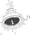
- the water extractor 32 includes a housing 34 having an inlet end 36 and an outlet end 38.
- the inlet end 36 may be configured to couple directly or indirectly to an outlet of a turbine.
- the outlet end 38 may be configured to couple the housing 34 with a downstream component (not shown) of the ECS 20, such as a heat exchanger or a converging outlet header for example.
- the outlet end 38 includes an outwardly extending flange 40 configured to facilitate a connection with the downstream component.
- the cross-sectional area of the housing 34 adjacent to or near the inlet end 36 is substantially smaller than the cross-sectional area of the housing at or adjacent to the outlet end 38.
- This change in the cross-sectional area is selected to cause a change in one or both of the pressure of the medium A and the speed of the medium A as is flows through the housing 34.
- the configuration of the housing 34 may be selected in part to achieve a flow at the outlet end 38 or upstream from the outlet end 38 having a desirable speed associated with one or more downstream components of the ECS 20.
- embodiments where the cross-sectional area at the outlet end 38 is substantially equal to or only slightly larger than the cross-sectional area at the inlet end 36 are also within the scope of the disclosure.
- the housing 34 may have a first portion 42 extending from the inlet end 36, and a second portion 44 extending from the outlet end 38, and a third portion 46 disposed between the first portion 42 and the second portion 44.
- the first portion 42 of the housing 34 has a substantially constant cross-sectional shape and area.
- the first portion 42 of the housing 34 is generally cylindrical; however, a first portion 42 having any suitable configuration is contemplated herein.
- a swirling mechanism may be arranged within the first portion 42 of the housing 34, such as at a location near the inlet end 36 for example. Such a swirling mechanism may be configured to impart a swirl or spin on the medium thereby enhancing the distribution of the medium A, and in particular the water within the medium A, across the entire area of the housing 34.
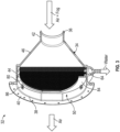
- the cross-sectional area and/or the cross-sectional shape of the third portion 46 of the housing 34 may vary over the axial length thereof. As a result of the change in the cross-sectional area of the third portion 46 along the axis, the third portion 46 may form a diffuser reducing the velocity and increasing the static pressure of the medium A.
- the third portion 46 of the housing 34 has a generally circular cross-section such that the third portion 46 is substantially frustoconical in shape.
- the second portion 44 of the housing 34 may have a generally constant cross-sectional shape and area. Although the second portion 44 of the housing 34 is illustrated as being generally cylindrical in shape it should be understood that a second portion 44 having another suitable configuration is contemplated herein. As best shown in FIG. 4 , in an embodiment, one or more sides of the circular wall that forms the second portion 44 may include one or more straight or linear sections 48. Although these straight sections are illustrated as being arranged at opposite lateral sides of the housing 34, embodiments where the at least one straight section is arranged elsewhere about the periphery of the second portion 44 are also contemplated herein.
- a fog harvester assembly 50 including at least one fog harvester insert 52.
- the fog harvester assembly 50 includes two fog harvester inserts 52.
- a fog harvester assembly 50 having any number of fog harvester inserts 52 including a single fog harvester insert, three fog harvester inserts, or more than three fog harvester inserts for example, are within the scope of the disclosure.
- the plurality of fog harvester inserts 52 are stacked relative to one another along the axis of the housing 34, such that the medium is configured to flow through the plurality of fog harvester inserts 52 in series. Further, in embodiments including multiple fog harvester inserts 52, the configuration of each of the plurality of fog harvester inserts 52 may be substantially identical, or alternatively, may be different.
- Each fog harvester insert 52 includes a frame 54 and a condensing material 56 installed about the frame 54.
- the frame 54 may be formed in any suitable manner including, but not limited to cast, injection molded, additively formed, and machined for example.
- the frame 54 is generally complementary to the corresponding portion of the housing 34 within which the fog harvester assembly 50 is received.
- the frame 54 defines a periphery of the fog harvester insert 52 and is generally circular in shape.
- the frame 54 may similarly include a straight section 58 positionable in alignment with the straight section 48 of the second portion 44 of the housing 34.
- the frame 54 is illustrated as only being arranged at a periphery of the fog harvester insert 52, embodiments where the frame 54 additionally includes at least one centrally located support extending between the sides of the frame 54 are also contemplated herein.
- one or more holes or elongated slots 60 are formed at or adjacent to the bottom surface 62 of the frame 54 to fluidly couple the bottom of the frame 54 with a sump or drain 64 formed in an adjacent surface of the housing 34.
- the at least one hole 60 includes a single slot extending about at least 20 degrees of the periphery, such as 30 degrees or more, or even 45 degrees or more.
- the slot 60 is shown as extending over only a portion of the width of the frame 54 (the slot is shown formed at a center of the frame 54), embodiments where the one or more holes 60 extend over a substantial entirety of the width of the frame 54 are also within the scope of the disclosure.
- the condensing material 56 includes a plurality of wires 72 arranged within an array, each wire has helical or spiral configuration.
- the wires 72 may be mounted relative to the frame 54 in a vertical orientation such that the wires 72 are parallel to one another and a first end of each wire 72 is coupled to a first end or top 66 of the frame 54 and a second end of each wire 72 is coupled to a second, opposite end or bottom 62 of the frame 54.
- embodiments where the wires 72 have another orientation are also contemplated herein.
- the plurality of wires 72 within the array may be made of any suitable material.
- suitable materials include, but are not limited to steel, steel alloys, copper, aluminum, other metals or metal alloys, composites, nylon, polyester, rayon, or another suitable polymer or plastic material, or any combination thereof.
- the wire array associated with each fog harvester insert 52 includes a plurality of rows of wires or strings 72 arranged in series relative to the flow through the housing 34. Although two rows of wires 72 are shown ( FIG. 6A-6C ), it should be understood that a fog harvester insert 52 having any number of rows of strings, including three rows, four rows, five rows, or more than five rows for example, are contemplated herein.
- Each row within the array includes one or more wires.
- the wires within each row may be positioned such that an outer periphery of the circular shape formed by the spiral of a first wire (in plan view) is directly adjacent to the circular shape formed by the spiral of a second wire (in plan view). Accordingly, the center of each spiral wire 72 is offset from the center of an adjacent spiral wire by a distance equal to an outer diameter of the circular shape of the spiral wires 72.
- the spirals of adjacent wires within a row are not configured to overlap or intertwine with one another.
- the spiral wires within adjacent rows such as the first wires of the plurality of rows for example, may also be arranged so as not to overlap or intertwine.
- spiral wires 72 within a row may also be arranged so as not to overlap or intertwine.
- the direction of the spiral of the wires 72, also referred to herein as the "spiral configuration" within a row is configured to vary.
- a first wire has a left-hand or clockwise configuration and a second wire, for example positioned directly adjacent to the first wire, has a right-hand or counter clockwise configuration.
- the first wire within adjacent rows may have alternating configurations.
- the plurality of fog harvester inserts 52 within the fog harvester assembly 50 are separated from one another by a distance.
- at least one spacer 74 such as a frame for example, may be arranged between adjacent fog harvester inserts 52.
- the spacer 74 is substantially identical to the frame 54 of a fog harvester insert 52.
- embodiments where a spacer 74 having a different configuration is used are also contemplated herein.
- the housing 34 is contoured or has an internal flange 76 (best shown in FIG. 3 ) arranged near the outlet end 38, for example near a downstream end of the third portion or diffuser 46 of the housing 34, and configured to support an internal end of the fog harvester assembly 50.
- the internal flange 76 restricts movement of the fog harvester assembly 50 in a first direction relative to the housing 34.
- the fog harvester assembly 50 may be sealed against the flange 76 such as via an O-ring type seal (not shown) for example.
- An end plate 80 is arranged in overlapping relationship with the most downstream fog harvester insert 52, located adjacent to the outlet end 38 of the housing 34.
- the end plate 80 has a substantially hollow center, similar to a frame 54 or spacer 74, to reduce interference with the flow output from the housing 34.
- a seal 82 such as an O-ring type seal for example, is positioned between the fog harvester assembly 50 and the end plate 80.
- a height (measured vertically) of a bottom lip 84 of the end plate 80 is greater than the vertical height of the bottom 62 of the frames 54 and/or spacers 74 of the fog harvester inserts 52.
- the enlarged bottom lip 84 of the end plate 80 prevents any condensation collected near the bottom of the frame of the fog harvester inserts from becoming entrained in the airflow at the outlet end 38.
- the condensing material 56 of the one or more fog harvester inserts 52 of the fog harvester assembly 50 extend generally vertically such that any moisture that collects on the wires 72 of the condensing material 56 will slide along the wires 60 towards the one or more holes 60 at the bottom 62 of the frame 54 in response to the gravity acting thereon.
- the fog harvester inserts 52 are generally described herein such that the condensing material 56 has a vertical orientation, embodiments where the condensing material 56 is arranged at a non-vertical angle relative to the longitudinal axis of the housing 34 are also within the scope of the disclosure.
- a plurality of fasteners may be used to couple the end plate 80 to a surface of the housing 34.
- a plurality of clips that use a threaded connection are illustrated in the FIGS., any suitable fastener is within the scope of the disclosure.
- the medium A is provided to the inlet end 36 of the water extractor 32.
- the medium A flows through the one or more fog harvester inserts 52 of the fog harvester assembly 50, water droplets collect on the surface of the wires 72 of the condensing material 56, or between adjacent layers of the condensing material 56, such as between two or more wires 72 for example.
- the medium A output from the water extractor 32 is dried or dehumidified compared to the inlet air.
- the gravitational force acting thereon will cause the droplets to slide down the condensing material 56 to the bottom of the frame 54.
- the water passes through the one or more holes 60 and drips from the end of the fog harvester insert 52 into the drain 64 disposed vertically underneath the fog harvester assembly 50. From the drain 64, the water can be exhausted overboard, or alternatively, can be redirected to another component of the ECS 20, or alternatively, to another system or component of the aircraft.
- water extractor 32 illustrated and described herein is intended to coalesce and collect the moisture within the medium A
- use of a water extractor 32 as described herein may minimize or even eliminate the need for a separate condenser located upstream from the water extractor 32 within the environmental control system.
Landscapes
- Engineering & Computer Science (AREA)
- Chemical & Material Sciences (AREA)
- Aviation & Aerospace Engineering (AREA)
- General Health & Medical Sciences (AREA)
- Pulmonology (AREA)
- Health & Medical Sciences (AREA)
- Chemical Kinetics & Catalysis (AREA)
- Physics & Mathematics (AREA)
- Thermal Sciences (AREA)
- Analytical Chemistry (AREA)
- General Chemical & Material Sciences (AREA)
- Oil, Petroleum & Natural Gas (AREA)
- Control Of Turbines (AREA)
- Extraction Or Liquid Replacement (AREA)
Claims (13)
- Wasserextraktor (32) zur Verwendung in einem Klimatisierungssystem, wobei der Wasserextraktor Folgendes umfasst:ein Gehäuse (34) mit einem Einlassende (36) und einem Auslassende (38); undeine Nebelfängeranordnung (50), die innerhalb des Gehäuses (34) an einer Stelle zwischen dem Einlassende (36) und dem Auslassende (38) montiert ist, wobei die Nebelfängeranordnung (50) mindestens einen Nebelfängereinsatz (52) mit einem kondensierenden Material (56) beinhaltet, das eine Vielzahl von Drähten (72) beinhaltet, die in einer Drahtanordnung angeordnet ist, wobei mindestens einer der Vielzahl von Drähten (72) eine spiralförmige Konfiguration aufweist;wobei das kondensierende Material (56) des mindestens einen Nebelfängereinsatzes an einem Rahmen (54) montiert ist, wobei in einer Unterseite des Rahmens (54) ein oder mehrere Löcher ausgebildet sind; und gekennzeichnet durch:
eine Endplatte (80), die in überlappender Anordnung mit dem mindestens einen Nebelfängereinsatz (52) positioniert ist, wobei die Endplatte (80) eine Unterlippe (84) aufweist, wobei eine Höhe der Unterlippe im Verhältnis zu einer Höhe der Unterseite des Rahmens (54) verlängert ist. - Wasserextraktor nach Anspruch 1, wobei das Gehäuse (34) einen Diffusor (46) beinhaltet, wobei die Nebelfängeranordnung an einem stromabwärtigen Ende des Diffusors angeordnet ist.
- Wasserextraktor nach Anspruch 1 oder 2, wobei die Nebelfängeranordnung (50) eine Vielzahl von Nebelfängereinsätzen (52) beinhaltet und wobei bevorzugt die Vielzahl von Nebelfängereinsätzen (52) entlang einer Achse des Gehäuses (34) voneinander getrennt ist, sodass ein Medium dazu konfiguriert ist, die Vielzahl von Nebelfängereinsätzen (52) nacheinander zu durchlaufen.
- Wasserextraktor nach Anspruch 3, ferner mindestens einen Abstandshalter (74) umfassend, der zwischen benachbarten Nebelfängereinsätzen (52) der Vielzahl von Nebelfängereinsätzen angeordnet ist.
- Wasserextraktor nach einem der vorhergehenden Ansprüche, wobei die Vielzahl von Drähten (72) der Drahtanordnung in mindestens zwei Reihen angeordnet ist.
- Wasserextraktor nach einem der vorhergehenden Ansprüche, wobei die spiralförmige Konfiguration benachbarter Drähte variiert.
- Wasserextraktor nach einem der vorhergehenden Ansprüche, wobei das kondensierende Material (56) des mindestens einen Nebelfängereinsatzes an einem Rahmen (54) montiert ist, wobei die Vielzahl von Drähten (72) relativ zu dem Rahmen (54) eine vertikale Ausrichtung aufweist.
- Wasserextraktor nach einem der vorhergehenden Ansprüche, wobei die Endplatte (80) ferner eine Vielzahl von Befestigungselementen (86) zum Befestigen der Nebelfängeranordnung (50) an dem Gehäuse (34) umfasst; und/oder ferner eine Dichtung (82), die zwischen der Endplatte (80) und dem mindestens einen Nebelfängereinsatz (52) positioniert ist, umfasst.
- Wasserextraktor nach einem der vorhergehenden Ansprüche, wobei das Gehäuse (34) ferner einen inneren Flansch (76) umfasst und die Bewegung der Nebelfängeranordnung in einer ersten Richtung durch den inneren Flansch eingeschränkt wird.
- Klimatisierungssystem eines Fahrzeugs, Folgendes umfassend:eine Komponente;den Wasserextraktor (32) nach einem der vorhergehenden Ansprüche, der stromabwärts der Komponente angeordnet ist und in Fluidkommunikation mit dieser relativ zu einem Medienfluss steht.
- Klimatisierungssystem nach Anspruch 10, wobei das Fahrzeug ein Luftfahrzeug ist.
- Klimatisierungssystem nach Anspruch 10 oder 11, wobei die Komponente eine Turbine ist.
- Klimatisierungssystem nach einem der Ansprüche 10-12 in Abhängigkeit von Anspruch 2, ferner einen in dem Gehäuse stromaufwärts des Diffusors montierten Wirbelmechanismus umfassend.
Applications Claiming Priority (1)
| Application Number | Priority Date | Filing Date | Title |
|---|---|---|---|
| US17/714,663 US12606311B2 (en) | 2022-04-06 | 2022-04-06 | Multi-pass spiral mesh screen assembly |
Publications (2)
| Publication Number | Publication Date |
|---|---|
| EP4257224A1 EP4257224A1 (de) | 2023-10-11 |
| EP4257224B1 true EP4257224B1 (de) | 2024-12-04 |
Family
ID=85873641
Family Applications (1)
| Application Number | Title | Priority Date | Filing Date |
|---|---|---|---|
| EP23166534.0A Active EP4257224B1 (de) | 2022-04-06 | 2023-04-04 | Spiralförmige mehrfachdurchgangs-maschensiebanordnung |
Country Status (2)
| Country | Link |
|---|---|
| US (1) | US12606311B2 (de) |
| EP (1) | EP4257224B1 (de) |
Families Citing this family (2)
| Publication number | Priority date | Publication date | Assignee | Title |
|---|---|---|---|---|
| US20260054215A1 (en) * | 2024-08-20 | 2026-02-26 | Hamilton Sundstrand Corporation | Rotating fog harp coalescer |
| US20250367573A1 (en) * | 2024-05-28 | 2025-12-04 | Hamilton Sundstrand Corporation | Architected lattice of lattice coalescer |
Family Cites Families (8)
| Publication number | Priority date | Publication date | Assignee | Title |
|---|---|---|---|---|
| DE257675C (de) * | 1910-12-31 | 1913-03-14 | Unger Arno | Apparat zum abscheiden flüssiger körper aus gasen und dämpfen mittels dicht beieinander, aufrecht hängend oderstehend in kammern angeordneter drähte |
| US3339349A (en) * | 1964-08-28 | 1967-09-05 | United Aircraft Corp | Coalescer |
| DE2753276A1 (de) | 1977-11-30 | 1979-05-31 | Otto Adelmann | Abscheider-vorrichtung |
| JP2014188409A (ja) | 2013-03-26 | 2014-10-06 | Toshiba Corp | 湿分分離器 |
| US10532311B2 (en) | 2017-06-30 | 2020-01-14 | Hamilton Sundstrand Corporation | Inert gas generation with dehumidification |
| FR3087878B1 (fr) | 2018-10-26 | 2020-10-09 | Liebherr Aerospace Toulouse Sas | Boucle d'extraction d'eau d'un systeme de conditionnement d'air d'une cabine d'un vehicule de transport aerien ou ferroviaire |
| US11154804B2 (en) * | 2018-12-07 | 2021-10-26 | Hamilton Sundstrand Corporation | Water extractors and methods of making water extractors |
| CN111408193A (zh) | 2020-04-07 | 2020-07-14 | 上海协升化工科技有限公司 | 一种管道在线气液分离器装置 |
-
2022
- 2022-04-06 US US17/714,663 patent/US12606311B2/en active Active
-
2023
- 2023-04-04 EP EP23166534.0A patent/EP4257224B1/de active Active
Also Published As
| Publication number | Publication date |
|---|---|
| US12606311B2 (en) | 2026-04-21 |
| US20230322391A1 (en) | 2023-10-12 |
| EP4257224A1 (de) | 2023-10-11 |
Similar Documents
| Publication | Publication Date | Title |
|---|---|---|
| EP4257224B1 (de) | Spiralförmige mehrfachdurchgangs-maschensiebanordnung | |
| US7779898B2 (en) | Heat transfer tube assembly with serpentine circuits | |
| EP4186579B1 (de) | Mitteldruckwassersammler für ein umgebungssteuerungssystem | |
| CN113227698B (zh) | 热交换器 | |
| US9016065B2 (en) | Coil arrangement for air intake system for gas turbine and methods | |
| EP3467392B1 (de) | Verbesserte hochdruck-wasserentnahmevorrichtung mit rasierkante, die eine niederdruckkammer speist, und interner spiralfunktion zur verbesserung der wasseraufnahme und -ableitung | |
| CN113227697A (zh) | 热交换器 | |
| CN1159565A (zh) | 具有整体式叠置通风冷凝器的蒸汽冷凝组件 | |
| KR950006505B1 (ko) | 핀이 설치된 액체입자 분리장치 | |
| CN101182965A (zh) | 制冷剂分配器和具有制冷剂分配器的空气调节器 | |
| KR102312111B1 (ko) | 원심력 및 충돌을 이용한 기액분리기 | |
| US11639800B2 (en) | Dehumidification drainage system with mist eliminator | |
| US20170045243A1 (en) | Water extractor device using scuppers | |
| CN117052672A (zh) | 油气分离装置及压缩机 | |
| US9476609B2 (en) | Water separator and system | |
| EP2673584B1 (de) | Vorrichtung zur gasbehandlung | |
| US20070125051A1 (en) | Duct wall water extractor | |
| JP2023162572A (ja) | 気液分離装置 | |
| US20260054206A1 (en) | Radial flow mid-pressure water separation for environmental control system | |
| EP4534173B1 (de) | Mitteldruck-wassertrennung für ein umgebungssteuerungssystem | |
| CN117006755B (en) | Oil separator and air conditioning unit | |
| EP4699935A1 (de) | Rotierender nebelkondensator | |
| US20240359123A1 (en) | Mid-pressure water collector (mpwc) with helical flow channel and radial scuppers | |
| CN117006755A (zh) | 油分离器及空调机组 | |
| NL8203971A (nl) | Gecombineerde dampvoorkoeler bij verdampingscondensors. |
Legal Events
| Date | Code | Title | Description |
|---|---|---|---|
| PUAI | Public reference made under article 153(3) epc to a published international application that has entered the european phase |
Free format text: ORIGINAL CODE: 0009012 |
|
| STAA | Information on the status of an ep patent application or granted ep patent |
Free format text: STATUS: THE APPLICATION HAS BEEN PUBLISHED |
|
| AK | Designated contracting states |
Kind code of ref document: A1 Designated state(s): AL AT BE BG CH CY CZ DE DK EE ES FI FR GB GR HR HU IE IS IT LI LT LU LV MC ME MK MT NL NO PL PT RO RS SE SI SK SM TR |
|
| STAA | Information on the status of an ep patent application or granted ep patent |
Free format text: STATUS: REQUEST FOR EXAMINATION WAS MADE |
|
| 17P | Request for examination filed |
Effective date: 20240408 |
|
| RBV | Designated contracting states (corrected) |
Designated state(s): AL AT BE BG CH CY CZ DE DK EE ES FI FR GB GR HR HU IE IS IT LI LT LU LV MC ME MK MT NL NO PL PT RO RS SE SI SK SM TR |
|
| GRAP | Despatch of communication of intention to grant a patent |
Free format text: ORIGINAL CODE: EPIDOSNIGR1 |
|
| STAA | Information on the status of an ep patent application or granted ep patent |
Free format text: STATUS: GRANT OF PATENT IS INTENDED |
|
| RIC1 | Information provided on ipc code assigned before grant |
Ipc: B64D 13/06 20060101ALI20240611BHEP Ipc: B01D 45/08 20060101AFI20240611BHEP |
|
| INTG | Intention to grant announced |
Effective date: 20240702 |
|
| GRAS | Grant fee paid |
Free format text: ORIGINAL CODE: EPIDOSNIGR3 |
|
| GRAA | (expected) grant |
Free format text: ORIGINAL CODE: 0009210 |
|
| STAA | Information on the status of an ep patent application or granted ep patent |
Free format text: STATUS: THE PATENT HAS BEEN GRANTED |
|
| AK | Designated contracting states |
Kind code of ref document: B1 Designated state(s): AL AT BE BG CH CY CZ DE DK EE ES FI FR GB GR HR HU IE IS IT LI LT LU LV MC ME MK MT NL NO PL PT RO RS SE SI SK SM TR |
|
| REG | Reference to a national code |
Ref country code: CH Ref legal event code: EP |
|
| REG | Reference to a national code |
Ref country code: DE Ref legal event code: R096 Ref document number: 602023001223 Country of ref document: DE |
|
| REG | Reference to a national code |
Ref country code: IE Ref legal event code: FG4D |
|
| REG | Reference to a national code |
Ref country code: LT Ref legal event code: MG9D |
|
| REG | Reference to a national code |
Ref country code: NL Ref legal event code: MP Effective date: 20241204 |
|
| PG25 | Lapsed in a contracting state [announced via postgrant information from national office to epo] |
Ref country code: HR Free format text: LAPSE BECAUSE OF FAILURE TO SUBMIT A TRANSLATION OF THE DESCRIPTION OR TO PAY THE FEE WITHIN THE PRESCRIBED TIME-LIMIT Effective date: 20241204 |
|
| PG25 | Lapsed in a contracting state [announced via postgrant information from national office to epo] |
Ref country code: FI Free format text: LAPSE BECAUSE OF FAILURE TO SUBMIT A TRANSLATION OF THE DESCRIPTION OR TO PAY THE FEE WITHIN THE PRESCRIBED TIME-LIMIT Effective date: 20241204 |
|
| PG25 | Lapsed in a contracting state [announced via postgrant information from national office to epo] |
Ref country code: BG Free format text: LAPSE BECAUSE OF FAILURE TO SUBMIT A TRANSLATION OF THE DESCRIPTION OR TO PAY THE FEE WITHIN THE PRESCRIBED TIME-LIMIT Effective date: 20241204 |
|
| PG25 | Lapsed in a contracting state [announced via postgrant information from national office to epo] |
Ref country code: ES Free format text: LAPSE BECAUSE OF FAILURE TO SUBMIT A TRANSLATION OF THE DESCRIPTION OR TO PAY THE FEE WITHIN THE PRESCRIBED TIME-LIMIT Effective date: 20241204 |
|
| PG25 | Lapsed in a contracting state [announced via postgrant information from national office to epo] |
Ref country code: NO Free format text: LAPSE BECAUSE OF FAILURE TO SUBMIT A TRANSLATION OF THE DESCRIPTION OR TO PAY THE FEE WITHIN THE PRESCRIBED TIME-LIMIT Effective date: 20250304 |
|
| PG25 | Lapsed in a contracting state [announced via postgrant information from national office to epo] |
Ref country code: GR Free format text: LAPSE BECAUSE OF FAILURE TO SUBMIT A TRANSLATION OF THE DESCRIPTION OR TO PAY THE FEE WITHIN THE PRESCRIBED TIME-LIMIT Effective date: 20250305 Ref country code: LV Free format text: LAPSE BECAUSE OF FAILURE TO SUBMIT A TRANSLATION OF THE DESCRIPTION OR TO PAY THE FEE WITHIN THE PRESCRIBED TIME-LIMIT Effective date: 20241204 |
|
| PG25 | Lapsed in a contracting state [announced via postgrant information from national office to epo] |
Ref country code: RS Free format text: LAPSE BECAUSE OF FAILURE TO SUBMIT A TRANSLATION OF THE DESCRIPTION OR TO PAY THE FEE WITHIN THE PRESCRIBED TIME-LIMIT Effective date: 20250304 |
|
| PG25 | Lapsed in a contracting state [announced via postgrant information from national office to epo] |
Ref country code: NL Free format text: LAPSE BECAUSE OF FAILURE TO SUBMIT A TRANSLATION OF THE DESCRIPTION OR TO PAY THE FEE WITHIN THE PRESCRIBED TIME-LIMIT Effective date: 20241204 |
|
| REG | Reference to a national code |
Ref country code: AT Ref legal event code: MK05 Ref document number: 1747565 Country of ref document: AT Kind code of ref document: T Effective date: 20241204 |
|
| PG25 | Lapsed in a contracting state [announced via postgrant information from national office to epo] |
Ref country code: SM Free format text: LAPSE BECAUSE OF FAILURE TO SUBMIT A TRANSLATION OF THE DESCRIPTION OR TO PAY THE FEE WITHIN THE PRESCRIBED TIME-LIMIT Effective date: 20241204 |
|
| PG25 | Lapsed in a contracting state [announced via postgrant information from national office to epo] |
Ref country code: PL Free format text: LAPSE BECAUSE OF FAILURE TO SUBMIT A TRANSLATION OF THE DESCRIPTION OR TO PAY THE FEE WITHIN THE PRESCRIBED TIME-LIMIT Effective date: 20241204 |
|
| PGFP | Annual fee paid to national office [announced via postgrant information from national office to epo] |
Ref country code: DE Payment date: 20250319 Year of fee payment: 3 |
|
| PG25 | Lapsed in a contracting state [announced via postgrant information from national office to epo] |
Ref country code: IS Free format text: LAPSE BECAUSE OF FAILURE TO SUBMIT A TRANSLATION OF THE DESCRIPTION OR TO PAY THE FEE WITHIN THE PRESCRIBED TIME-LIMIT Effective date: 20250404 |
|
| PG25 | Lapsed in a contracting state [announced via postgrant information from national office to epo] |
Ref country code: PT Free format text: LAPSE BECAUSE OF FAILURE TO SUBMIT A TRANSLATION OF THE DESCRIPTION OR TO PAY THE FEE WITHIN THE PRESCRIBED TIME-LIMIT Effective date: 20250404 |
|
| PG25 | Lapsed in a contracting state [announced via postgrant information from national office to epo] |
Ref country code: EE Free format text: LAPSE BECAUSE OF FAILURE TO SUBMIT A TRANSLATION OF THE DESCRIPTION OR TO PAY THE FEE WITHIN THE PRESCRIBED TIME-LIMIT Effective date: 20241204 |
|
| PG25 | Lapsed in a contracting state [announced via postgrant information from national office to epo] |
Ref country code: RO Free format text: LAPSE BECAUSE OF FAILURE TO SUBMIT A TRANSLATION OF THE DESCRIPTION OR TO PAY THE FEE WITHIN THE PRESCRIBED TIME-LIMIT Effective date: 20241204 Ref country code: AT Free format text: LAPSE BECAUSE OF FAILURE TO SUBMIT A TRANSLATION OF THE DESCRIPTION OR TO PAY THE FEE WITHIN THE PRESCRIBED TIME-LIMIT Effective date: 20241204 |
|
| PG25 | Lapsed in a contracting state [announced via postgrant information from national office to epo] |
Ref country code: SK Free format text: LAPSE BECAUSE OF FAILURE TO SUBMIT A TRANSLATION OF THE DESCRIPTION OR TO PAY THE FEE WITHIN THE PRESCRIBED TIME-LIMIT Effective date: 20241204 |
|
| PG25 | Lapsed in a contracting state [announced via postgrant information from national office to epo] |
Ref country code: CZ Free format text: LAPSE BECAUSE OF FAILURE TO SUBMIT A TRANSLATION OF THE DESCRIPTION OR TO PAY THE FEE WITHIN THE PRESCRIBED TIME-LIMIT Effective date: 20241204 |
|
| PG25 | Lapsed in a contracting state [announced via postgrant information from national office to epo] |
Ref country code: IT Free format text: LAPSE BECAUSE OF FAILURE TO SUBMIT A TRANSLATION OF THE DESCRIPTION OR TO PAY THE FEE WITHIN THE PRESCRIBED TIME-LIMIT Effective date: 20241204 |
|
| REG | Reference to a national code |
Ref country code: DE Ref legal event code: R097 Ref document number: 602023001223 Country of ref document: DE |
|
| PG25 | Lapsed in a contracting state [announced via postgrant information from national office to epo] |
Ref country code: SE Free format text: LAPSE BECAUSE OF FAILURE TO SUBMIT A TRANSLATION OF THE DESCRIPTION OR TO PAY THE FEE WITHIN THE PRESCRIBED TIME-LIMIT Effective date: 20241204 |
|
| PG25 | Lapsed in a contracting state [announced via postgrant information from national office to epo] |
Ref country code: DK Free format text: LAPSE BECAUSE OF FAILURE TO SUBMIT A TRANSLATION OF THE DESCRIPTION OR TO PAY THE FEE WITHIN THE PRESCRIBED TIME-LIMIT Effective date: 20241204 |
|
| PLBE | No opposition filed within time limit |
Free format text: ORIGINAL CODE: 0009261 |
|
| STAA | Information on the status of an ep patent application or granted ep patent |
Free format text: STATUS: NO OPPOSITION FILED WITHIN TIME LIMIT |
|
| 26N | No opposition filed |
Effective date: 20250905 |
|
| PG25 | Lapsed in a contracting state [announced via postgrant information from national office to epo] |
Ref country code: LU Free format text: LAPSE BECAUSE OF NON-PAYMENT OF DUE FEES Effective date: 20250404 |
|
| PG25 | Lapsed in a contracting state [announced via postgrant information from national office to epo] |
Ref country code: MC Free format text: LAPSE BECAUSE OF FAILURE TO SUBMIT A TRANSLATION OF THE DESCRIPTION OR TO PAY THE FEE WITHIN THE PRESCRIBED TIME-LIMIT Effective date: 20241204 |
|
| REG | Reference to a national code |
Ref country code: BE Ref legal event code: MM Effective date: 20250430 |
|
| PG25 | Lapsed in a contracting state [announced via postgrant information from national office to epo] |
Ref country code: BE Free format text: LAPSE BECAUSE OF NON-PAYMENT OF DUE FEES Effective date: 20250430 |
|
| PG25 | Lapsed in a contracting state [announced via postgrant information from national office to epo] |
Ref country code: IE Free format text: LAPSE BECAUSE OF NON-PAYMENT OF DUE FEES Effective date: 20250404 |
|
| PGFP | Annual fee paid to national office [announced via postgrant information from national office to epo] |
Ref country code: FR Payment date: 20260319 Year of fee payment: 4 |