EP4257090A2 - Shoulder prosthesis components and assemblies - Google Patents
Shoulder prosthesis components and assemblies Download PDFInfo
- Publication number
- EP4257090A2 EP4257090A2 EP23194764.9A EP23194764A EP4257090A2 EP 4257090 A2 EP4257090 A2 EP 4257090A2 EP 23194764 A EP23194764 A EP 23194764A EP 4257090 A2 EP4257090 A2 EP 4257090A2
- Authority
- EP
- European Patent Office
- Prior art keywords
- anchor
- humeral
- humeral anchor
- collar
- interior surface
- Prior art date
- Legal status (The legal status is an assumption and is not a legal conclusion. Google has not performed a legal analysis and makes no representation as to the accuracy of the status listed.)
- Pending
Links
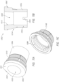
Images


















Classifications
-
- A—HUMAN NECESSITIES
- A61—MEDICAL OR VETERINARY SCIENCE; HYGIENE
- A61F—FILTERS IMPLANTABLE INTO BLOOD VESSELS; PROSTHESES; DEVICES PROVIDING PATENCY TO, OR PREVENTING COLLAPSING OF, TUBULAR STRUCTURES OF THE BODY, e.g. STENTS; ORTHOPAEDIC, NURSING OR CONTRACEPTIVE DEVICES; FOMENTATION; TREATMENT OR PROTECTION OF EYES OR EARS; BANDAGES, DRESSINGS OR ABSORBENT PADS; FIRST-AID KITS
- A61F2/00—Filters implantable into blood vessels; Prostheses, i.e. artificial substitutes or replacements for parts of the body; Appliances for connecting them with the body; Devices providing patency to, or preventing collapsing of, tubular structures of the body, e.g. stents
- A61F2/02—Prostheses implantable into the body
- A61F2/30—Joints
- A61F2/40—Joints for shoulders
- A61F2/4014—Humeral heads or necks; Connections of endoprosthetic heads or necks to endoprosthetic humeral shafts
-
- A—HUMAN NECESSITIES
- A61—MEDICAL OR VETERINARY SCIENCE; HYGIENE
- A61F—FILTERS IMPLANTABLE INTO BLOOD VESSELS; PROSTHESES; DEVICES PROVIDING PATENCY TO, OR PREVENTING COLLAPSING OF, TUBULAR STRUCTURES OF THE BODY, e.g. STENTS; ORTHOPAEDIC, NURSING OR CONTRACEPTIVE DEVICES; FOMENTATION; TREATMENT OR PROTECTION OF EYES OR EARS; BANDAGES, DRESSINGS OR ABSORBENT PADS; FIRST-AID KITS
- A61F2/00—Filters implantable into blood vessels; Prostheses, i.e. artificial substitutes or replacements for parts of the body; Appliances for connecting them with the body; Devices providing patency to, or preventing collapsing of, tubular structures of the body, e.g. stents
- A61F2/02—Prostheses implantable into the body
- A61F2/30—Joints
- A61F2/30721—Accessories
- A61F2/30749—Fixation appliances for connecting prostheses to the body
-
- A—HUMAN NECESSITIES
- A61—MEDICAL OR VETERINARY SCIENCE; HYGIENE
- A61F—FILTERS IMPLANTABLE INTO BLOOD VESSELS; PROSTHESES; DEVICES PROVIDING PATENCY TO, OR PREVENTING COLLAPSING OF, TUBULAR STRUCTURES OF THE BODY, e.g. STENTS; ORTHOPAEDIC, NURSING OR CONTRACEPTIVE DEVICES; FOMENTATION; TREATMENT OR PROTECTION OF EYES OR EARS; BANDAGES, DRESSINGS OR ABSORBENT PADS; FIRST-AID KITS
- A61F2/00—Filters implantable into blood vessels; Prostheses, i.e. artificial substitutes or replacements for parts of the body; Appliances for connecting them with the body; Devices providing patency to, or preventing collapsing of, tubular structures of the body, e.g. stents
- A61F2/02—Prostheses implantable into the body
- A61F2/30—Joints
- A61F2/30767—Special external or bone-contacting surface, e.g. coating for improving bone ingrowth
- A61F2/30771—Special external or bone-contacting surface, e.g. coating for improving bone ingrowth applied in original prostheses, e.g. holes or grooves
-
- A—HUMAN NECESSITIES
- A61—MEDICAL OR VETERINARY SCIENCE; HYGIENE
- A61F—FILTERS IMPLANTABLE INTO BLOOD VESSELS; PROSTHESES; DEVICES PROVIDING PATENCY TO, OR PREVENTING COLLAPSING OF, TUBULAR STRUCTURES OF THE BODY, e.g. STENTS; ORTHOPAEDIC, NURSING OR CONTRACEPTIVE DEVICES; FOMENTATION; TREATMENT OR PROTECTION OF EYES OR EARS; BANDAGES, DRESSINGS OR ABSORBENT PADS; FIRST-AID KITS
- A61F2/00—Filters implantable into blood vessels; Prostheses, i.e. artificial substitutes or replacements for parts of the body; Appliances for connecting them with the body; Devices providing patency to, or preventing collapsing of, tubular structures of the body, e.g. stents
- A61F2/02—Prostheses implantable into the body
- A61F2/30—Joints
- A61F2/40—Joints for shoulders
- A61F2/4003—Replacing only the epiphyseal or metaphyseal parts of the humerus, i.e. endoprosthesis not comprising an entire humeral shaft
-
- A—HUMAN NECESSITIES
- A61—MEDICAL OR VETERINARY SCIENCE; HYGIENE
- A61F—FILTERS IMPLANTABLE INTO BLOOD VESSELS; PROSTHESES; DEVICES PROVIDING PATENCY TO, OR PREVENTING COLLAPSING OF, TUBULAR STRUCTURES OF THE BODY, e.g. STENTS; ORTHOPAEDIC, NURSING OR CONTRACEPTIVE DEVICES; FOMENTATION; TREATMENT OR PROTECTION OF EYES OR EARS; BANDAGES, DRESSINGS OR ABSORBENT PADS; FIRST-AID KITS
- A61F2/00—Filters implantable into blood vessels; Prostheses, i.e. artificial substitutes or replacements for parts of the body; Appliances for connecting them with the body; Devices providing patency to, or preventing collapsing of, tubular structures of the body, e.g. stents
- A61F2/02—Prostheses implantable into the body
- A61F2/30—Joints
- A61F2/46—Special tools for implanting artificial joints
- A61F2/4603—Special tools for implanting artificial joints for insertion or extraction of endoprosthetic joints or of accessories thereof
- A61F2/4612—Special tools for implanting artificial joints for insertion or extraction of endoprosthetic joints or of accessories thereof of shoulders
-
- A—HUMAN NECESSITIES
- A61—MEDICAL OR VETERINARY SCIENCE; HYGIENE
- A61F—FILTERS IMPLANTABLE INTO BLOOD VESSELS; PROSTHESES; DEVICES PROVIDING PATENCY TO, OR PREVENTING COLLAPSING OF, TUBULAR STRUCTURES OF THE BODY, e.g. STENTS; ORTHOPAEDIC, NURSING OR CONTRACEPTIVE DEVICES; FOMENTATION; TREATMENT OR PROTECTION OF EYES OR EARS; BANDAGES, DRESSINGS OR ABSORBENT PADS; FIRST-AID KITS
- A61F2/00—Filters implantable into blood vessels; Prostheses, i.e. artificial substitutes or replacements for parts of the body; Appliances for connecting them with the body; Devices providing patency to, or preventing collapsing of, tubular structures of the body, e.g. stents
- A61F2/02—Prostheses implantable into the body
- A61F2/30—Joints
- A61F2002/30001—Additional features of subject-matter classified in A61F2/28, A61F2/30 and subgroups thereof
- A61F2002/30003—Material related properties of the prosthesis or of a coating on the prosthesis
- A61F2002/30004—Material related properties of the prosthesis or of a coating on the prosthesis the prosthesis being made from materials having different values of a given property at different locations within the same prosthesis
- A61F2002/30011—Material related properties of the prosthesis or of a coating on the prosthesis the prosthesis being made from materials having different values of a given property at different locations within the same prosthesis differing in porosity
-
- A—HUMAN NECESSITIES
- A61—MEDICAL OR VETERINARY SCIENCE; HYGIENE
- A61F—FILTERS IMPLANTABLE INTO BLOOD VESSELS; PROSTHESES; DEVICES PROVIDING PATENCY TO, OR PREVENTING COLLAPSING OF, TUBULAR STRUCTURES OF THE BODY, e.g. STENTS; ORTHOPAEDIC, NURSING OR CONTRACEPTIVE DEVICES; FOMENTATION; TREATMENT OR PROTECTION OF EYES OR EARS; BANDAGES, DRESSINGS OR ABSORBENT PADS; FIRST-AID KITS
- A61F2/00—Filters implantable into blood vessels; Prostheses, i.e. artificial substitutes or replacements for parts of the body; Appliances for connecting them with the body; Devices providing patency to, or preventing collapsing of, tubular structures of the body, e.g. stents
- A61F2/02—Prostheses implantable into the body
- A61F2/30—Joints
- A61F2002/30001—Additional features of subject-matter classified in A61F2/28, A61F2/30 and subgroups thereof
- A61F2002/30108—Shapes
- A61F2002/30199—Three-dimensional shapes
- A61F2002/30224—Three-dimensional shapes cylindrical
-
- A—HUMAN NECESSITIES
- A61—MEDICAL OR VETERINARY SCIENCE; HYGIENE
- A61F—FILTERS IMPLANTABLE INTO BLOOD VESSELS; PROSTHESES; DEVICES PROVIDING PATENCY TO, OR PREVENTING COLLAPSING OF, TUBULAR STRUCTURES OF THE BODY, e.g. STENTS; ORTHOPAEDIC, NURSING OR CONTRACEPTIVE DEVICES; FOMENTATION; TREATMENT OR PROTECTION OF EYES OR EARS; BANDAGES, DRESSINGS OR ABSORBENT PADS; FIRST-AID KITS
- A61F2/00—Filters implantable into blood vessels; Prostheses, i.e. artificial substitutes or replacements for parts of the body; Appliances for connecting them with the body; Devices providing patency to, or preventing collapsing of, tubular structures of the body, e.g. stents
- A61F2/02—Prostheses implantable into the body
- A61F2/30—Joints
- A61F2002/30001—Additional features of subject-matter classified in A61F2/28, A61F2/30 and subgroups thereof
- A61F2002/30316—The prosthesis having different structural features at different locations within the same prosthesis; Connections between prosthetic parts; Special structural features of bone or joint prostheses not otherwise provided for
- A61F2002/30329—Connections or couplings between prosthetic parts, e.g. between modular parts; Connecting elements
- A61F2002/30383—Connections or couplings between prosthetic parts, e.g. between modular parts; Connecting elements made by laterally inserting a protrusion, e.g. a rib into a complementarily-shaped groove
-
- A—HUMAN NECESSITIES
- A61—MEDICAL OR VETERINARY SCIENCE; HYGIENE
- A61F—FILTERS IMPLANTABLE INTO BLOOD VESSELS; PROSTHESES; DEVICES PROVIDING PATENCY TO, OR PREVENTING COLLAPSING OF, TUBULAR STRUCTURES OF THE BODY, e.g. STENTS; ORTHOPAEDIC, NURSING OR CONTRACEPTIVE DEVICES; FOMENTATION; TREATMENT OR PROTECTION OF EYES OR EARS; BANDAGES, DRESSINGS OR ABSORBENT PADS; FIRST-AID KITS
- A61F2/00—Filters implantable into blood vessels; Prostheses, i.e. artificial substitutes or replacements for parts of the body; Appliances for connecting them with the body; Devices providing patency to, or preventing collapsing of, tubular structures of the body, e.g. stents
- A61F2/02—Prostheses implantable into the body
- A61F2/30—Joints
- A61F2002/30001—Additional features of subject-matter classified in A61F2/28, A61F2/30 and subgroups thereof
- A61F2002/30316—The prosthesis having different structural features at different locations within the same prosthesis; Connections between prosthetic parts; Special structural features of bone or joint prostheses not otherwise provided for
- A61F2002/30329—Connections or couplings between prosthetic parts, e.g. between modular parts; Connecting elements
- A61F2002/30428—Connections or couplings between prosthetic parts, e.g. between modular parts; Connecting elements made by inserting a protrusion into a slot
-
- A—HUMAN NECESSITIES
- A61—MEDICAL OR VETERINARY SCIENCE; HYGIENE
- A61F—FILTERS IMPLANTABLE INTO BLOOD VESSELS; PROSTHESES; DEVICES PROVIDING PATENCY TO, OR PREVENTING COLLAPSING OF, TUBULAR STRUCTURES OF THE BODY, e.g. STENTS; ORTHOPAEDIC, NURSING OR CONTRACEPTIVE DEVICES; FOMENTATION; TREATMENT OR PROTECTION OF EYES OR EARS; BANDAGES, DRESSINGS OR ABSORBENT PADS; FIRST-AID KITS
- A61F2/00—Filters implantable into blood vessels; Prostheses, i.e. artificial substitutes or replacements for parts of the body; Appliances for connecting them with the body; Devices providing patency to, or preventing collapsing of, tubular structures of the body, e.g. stents
- A61F2/02—Prostheses implantable into the body
- A61F2/30—Joints
- A61F2002/30001—Additional features of subject-matter classified in A61F2/28, A61F2/30 and subgroups thereof
- A61F2002/30316—The prosthesis having different structural features at different locations within the same prosthesis; Connections between prosthetic parts; Special structural features of bone or joint prostheses not otherwise provided for
- A61F2002/30329—Connections or couplings between prosthetic parts, e.g. between modular parts; Connecting elements
- A61F2002/30476—Connections or couplings between prosthetic parts, e.g. between modular parts; Connecting elements locked by an additional locking mechanism
- A61F2002/30495—Connections or couplings between prosthetic parts, e.g. between modular parts; Connecting elements locked by an additional locking mechanism using a locking ring
-
- A—HUMAN NECESSITIES
- A61—MEDICAL OR VETERINARY SCIENCE; HYGIENE
- A61F—FILTERS IMPLANTABLE INTO BLOOD VESSELS; PROSTHESES; DEVICES PROVIDING PATENCY TO, OR PREVENTING COLLAPSING OF, TUBULAR STRUCTURES OF THE BODY, e.g. STENTS; ORTHOPAEDIC, NURSING OR CONTRACEPTIVE DEVICES; FOMENTATION; TREATMENT OR PROTECTION OF EYES OR EARS; BANDAGES, DRESSINGS OR ABSORBENT PADS; FIRST-AID KITS
- A61F2/00—Filters implantable into blood vessels; Prostheses, i.e. artificial substitutes or replacements for parts of the body; Appliances for connecting them with the body; Devices providing patency to, or preventing collapsing of, tubular structures of the body, e.g. stents
- A61F2/02—Prostheses implantable into the body
- A61F2/30—Joints
- A61F2002/30001—Additional features of subject-matter classified in A61F2/28, A61F2/30 and subgroups thereof
- A61F2002/30316—The prosthesis having different structural features at different locations within the same prosthesis; Connections between prosthetic parts; Special structural features of bone or joint prostheses not otherwise provided for
- A61F2002/30535—Special structural features of bone or joint prostheses not otherwise provided for
- A61F2002/30604—Special structural features of bone or joint prostheses not otherwise provided for modular
- A61F2002/30607—Kits of prosthetic parts to be assembled in various combinations for forming different prostheses
-
- A—HUMAN NECESSITIES
- A61—MEDICAL OR VETERINARY SCIENCE; HYGIENE
- A61F—FILTERS IMPLANTABLE INTO BLOOD VESSELS; PROSTHESES; DEVICES PROVIDING PATENCY TO, OR PREVENTING COLLAPSING OF, TUBULAR STRUCTURES OF THE BODY, e.g. STENTS; ORTHOPAEDIC, NURSING OR CONTRACEPTIVE DEVICES; FOMENTATION; TREATMENT OR PROTECTION OF EYES OR EARS; BANDAGES, DRESSINGS OR ABSORBENT PADS; FIRST-AID KITS
- A61F2/00—Filters implantable into blood vessels; Prostheses, i.e. artificial substitutes or replacements for parts of the body; Appliances for connecting them with the body; Devices providing patency to, or preventing collapsing of, tubular structures of the body, e.g. stents
- A61F2/02—Prostheses implantable into the body
- A61F2/30—Joints
- A61F2/30767—Special external or bone-contacting surface, e.g. coating for improving bone ingrowth
- A61F2/30771—Special external or bone-contacting surface, e.g. coating for improving bone ingrowth applied in original prostheses, e.g. holes or grooves
- A61F2002/30878—Special external or bone-contacting surface, e.g. coating for improving bone ingrowth applied in original prostheses, e.g. holes or grooves with non-sharp protrusions, for instance contacting the bone for anchoring, e.g. keels, pegs, pins, posts, shanks, stems, struts
- A61F2002/30884—Fins or wings, e.g. longitudinal wings for preventing rotation within the bone cavity
-
- A—HUMAN NECESSITIES
- A61—MEDICAL OR VETERINARY SCIENCE; HYGIENE
- A61F—FILTERS IMPLANTABLE INTO BLOOD VESSELS; PROSTHESES; DEVICES PROVIDING PATENCY TO, OR PREVENTING COLLAPSING OF, TUBULAR STRUCTURES OF THE BODY, e.g. STENTS; ORTHOPAEDIC, NURSING OR CONTRACEPTIVE DEVICES; FOMENTATION; TREATMENT OR PROTECTION OF EYES OR EARS; BANDAGES, DRESSINGS OR ABSORBENT PADS; FIRST-AID KITS
- A61F2/00—Filters implantable into blood vessels; Prostheses, i.e. artificial substitutes or replacements for parts of the body; Appliances for connecting them with the body; Devices providing patency to, or preventing collapsing of, tubular structures of the body, e.g. stents
- A61F2/02—Prostheses implantable into the body
- A61F2/30—Joints
- A61F2/30767—Special external or bone-contacting surface, e.g. coating for improving bone ingrowth
- A61F2002/3093—Special external or bone-contacting surface, e.g. coating for improving bone ingrowth for promoting ingrowth of bone tissue
-
- A—HUMAN NECESSITIES
- A61—MEDICAL OR VETERINARY SCIENCE; HYGIENE
- A61F—FILTERS IMPLANTABLE INTO BLOOD VESSELS; PROSTHESES; DEVICES PROVIDING PATENCY TO, OR PREVENTING COLLAPSING OF, TUBULAR STRUCTURES OF THE BODY, e.g. STENTS; ORTHOPAEDIC, NURSING OR CONTRACEPTIVE DEVICES; FOMENTATION; TREATMENT OR PROTECTION OF EYES OR EARS; BANDAGES, DRESSINGS OR ABSORBENT PADS; FIRST-AID KITS
- A61F2/00—Filters implantable into blood vessels; Prostheses, i.e. artificial substitutes or replacements for parts of the body; Appliances for connecting them with the body; Devices providing patency to, or preventing collapsing of, tubular structures of the body, e.g. stents
- A61F2/02—Prostheses implantable into the body
- A61F2/30—Joints
- A61F2/40—Joints for shoulders
- A61F2/4014—Humeral heads or necks; Connections of endoprosthetic heads or necks to endoprosthetic humeral shafts
- A61F2002/4018—Heads or epiphyseal parts of humerus
- A61F2002/4022—Heads or epiphyseal parts of humerus having a concave shape, e.g. hemispherical cups
-
- A—HUMAN NECESSITIES
- A61—MEDICAL OR VETERINARY SCIENCE; HYGIENE
- A61F—FILTERS IMPLANTABLE INTO BLOOD VESSELS; PROSTHESES; DEVICES PROVIDING PATENCY TO, OR PREVENTING COLLAPSING OF, TUBULAR STRUCTURES OF THE BODY, e.g. STENTS; ORTHOPAEDIC, NURSING OR CONTRACEPTIVE DEVICES; FOMENTATION; TREATMENT OR PROTECTION OF EYES OR EARS; BANDAGES, DRESSINGS OR ABSORBENT PADS; FIRST-AID KITS
- A61F2/00—Filters implantable into blood vessels; Prostheses, i.e. artificial substitutes or replacements for parts of the body; Appliances for connecting them with the body; Devices providing patency to, or preventing collapsing of, tubular structures of the body, e.g. stents
- A61F2/02—Prostheses implantable into the body
- A61F2/30—Joints
- A61F2/40—Joints for shoulders
- A61F2/4014—Humeral heads or necks; Connections of endoprosthetic heads or necks to endoprosthetic humeral shafts
- A61F2002/4051—Connections of heads directly to shafts
-
- A—HUMAN NECESSITIES
- A61—MEDICAL OR VETERINARY SCIENCE; HYGIENE
- A61F—FILTERS IMPLANTABLE INTO BLOOD VESSELS; PROSTHESES; DEVICES PROVIDING PATENCY TO, OR PREVENTING COLLAPSING OF, TUBULAR STRUCTURES OF THE BODY, e.g. STENTS; ORTHOPAEDIC, NURSING OR CONTRACEPTIVE DEVICES; FOMENTATION; TREATMENT OR PROTECTION OF EYES OR EARS; BANDAGES, DRESSINGS OR ABSORBENT PADS; FIRST-AID KITS
- A61F2/00—Filters implantable into blood vessels; Prostheses, i.e. artificial substitutes or replacements for parts of the body; Appliances for connecting them with the body; Devices providing patency to, or preventing collapsing of, tubular structures of the body, e.g. stents
- A61F2/02—Prostheses implantable into the body
- A61F2/30—Joints
- A61F2/40—Joints for shoulders
- A61F2/4059—Humeral shafts
- A61F2002/4062—Proximal or metaphyseal parts of shafts
-
- A—HUMAN NECESSITIES
- A61—MEDICAL OR VETERINARY SCIENCE; HYGIENE
- A61F—FILTERS IMPLANTABLE INTO BLOOD VESSELS; PROSTHESES; DEVICES PROVIDING PATENCY TO, OR PREVENTING COLLAPSING OF, TUBULAR STRUCTURES OF THE BODY, e.g. STENTS; ORTHOPAEDIC, NURSING OR CONTRACEPTIVE DEVICES; FOMENTATION; TREATMENT OR PROTECTION OF EYES OR EARS; BANDAGES, DRESSINGS OR ABSORBENT PADS; FIRST-AID KITS
- A61F2/00—Filters implantable into blood vessels; Prostheses, i.e. artificial substitutes or replacements for parts of the body; Appliances for connecting them with the body; Devices providing patency to, or preventing collapsing of, tubular structures of the body, e.g. stents
- A61F2/02—Prostheses implantable into the body
- A61F2/30—Joints
- A61F2/40—Joints for shoulders
- A61F2/4059—Humeral shafts
- A61F2002/4077—Distal or diaphyseal parts of shafts
-
- A—HUMAN NECESSITIES
- A61—MEDICAL OR VETERINARY SCIENCE; HYGIENE
- A61F—FILTERS IMPLANTABLE INTO BLOOD VESSELS; PROSTHESES; DEVICES PROVIDING PATENCY TO, OR PREVENTING COLLAPSING OF, TUBULAR STRUCTURES OF THE BODY, e.g. STENTS; ORTHOPAEDIC, NURSING OR CONTRACEPTIVE DEVICES; FOMENTATION; TREATMENT OR PROTECTION OF EYES OR EARS; BANDAGES, DRESSINGS OR ABSORBENT PADS; FIRST-AID KITS
- A61F2/00—Filters implantable into blood vessels; Prostheses, i.e. artificial substitutes or replacements for parts of the body; Appliances for connecting them with the body; Devices providing patency to, or preventing collapsing of, tubular structures of the body, e.g. stents
- A61F2/02—Prostheses implantable into the body
- A61F2/30—Joints
- A61F2/40—Joints for shoulders
- A61F2/4081—Glenoid components, e.g. cups
- A61F2002/4085—Glenoid components, e.g. cups having a convex shape, e.g. hemispherical heads
Definitions
- the present invention relates to a humeral anchor.
- the invention also relates to a kit comprising such a humeral anchor.
- the present application is directed to apparatuses and methods for reverse and anatomic shoulder prostheses.
- Arthroplasty is the standard of care for the treatment of shoulder joint arthritis.
- a typical anatomical shoulder joint replacement attempts to mimic anatomic conditions.
- a metallic humeral stem and a humeral head replacement are attached to the humerus of the arm and replace the humeral side of the arthritic shoulder joint.
- Such humeral head replacement can articulate with the native glenoid socket or with an opposing glenoid resurfacing device.
- a reverse shoulder prosthesis can be provided by securing a semi-spherical device (sometimes called a glenoid sphere) to the glenoid and implanting a humeral stem with a cavity capable of receiving the glenoid sphere.
- a semi-spherical device sometimes called a glenoid sphere
- humeral components, assemblies, and methods are needed to provide more flexibility in working with soft tissue around the shoulder joint. Such components may benefit from placement of at least a portion of the humeral anchor below a humerus resection plane. Such components may benefit from placement of at least a portion of the humeral anchor and also at least a locking portion of an articular assembly below a humerus resection plane.
- An object of the present invention is a humeral anchor as defined in claim 1.
- a humeral anchor in one embodiment, can include a first end and a second end.
- the humeral anchor can include an interior surface extending between the first end and the second end, the interior surface disposed about a recess disposed between the first end and the second end.
- the recess can be configured to secure a coupling of a shoulder articular body directly to the interior surface.
- a transverse surface can be configured to engage a humeral bone layer exposed by resection or other preparation when the humeral anchor is implanted to resist subsidence.
- the transverse surface can comprise a portion of a collar disposed at the first end of the humeral anchor.
- the transverse surface can comprise an anti-rotation feature disposed between the first end and the second end of the humeral anchor.
- the interior surface can comprise a tapered surface for engaging an articular assembly.
- the interior surface can be disposed about the interior surface comprises a slot for engaging an articular assembly.
- An exterior surface having a porous surface can be at least partially bounded by a non-porous edge, the non-porous edge being disposed between the porous surface and the second end.
- the interior surface can comprise a first taper disposed towards the first end and a second taper disposed towards the second end.
- An exterior surface having a first tapered portion can be disposed about the first end and a second tapered portion can be disposed about a portion of the humeral anchor between the first tapered portion and the second end of the humeral anchor, the second tapered portion being discontinuous from the first tapered portion.
- the first tapered portion can have a first angle away from an axis disposed from the first end to the second end and the second tapered portion can have a second angle away from the axis disposed from the first end to the second end, the second angle being greater than the first angle.
- the interior surface can comprise a groove configured to receive a locking ring of an articular body assembly.
- the humeral anchor can include a plurality of struts disposed about an exterior surface of the humeral anchor between the first end and the second end.
- a porous surface can be disposed between at least two struts of the plurality of struts.
- a plurality of struts can be disposed about an exterior surface of the humeral anchor.
- the exterior surface can have a first portion disposed about the first end and a second portion between the first portion and the second end of the humeral anchor, the struts being disposed about the first portion.
- a first plurality of struts can be disposed about the first portion and at least one strut is disposed about the second portion.
- the first plurality of struts can have twice as many struts as the second plurality of struts.
- the struts can be disposed about the second portion.
- the struts can be configured to reduce, minimize or eliminate rotation of the humeral anchor.
- a kit can include a first humeral comprising a first humeral anchor exterior surface and a first collar disposed at the first end thereof.
- the kit can include a second humeral anchor comprising a second humeral anchor exterior surface and a second collar disposed at the first end thereof.
- the first humeral anchor and the second humeral anchor can have identical interior surfaces.
- the first collar and the second collar can have the same outer perimeter dimensions.
- the second humeral anchor exterior surface can be larger than the first humeral anchor exterior surface.
- the humeral anchor can have at least one fin configured to reduce, minimize or eliminate rotation of the humeral anchor when the humeral anchor is implanted in bone of a humerus.
- the fin can be disposed at the second end of the humeral anchor.
- an array of fins can be disposed radially at the second end of the humeral anchor.
- a stemmed anchor can include the humeral anchor and a stem coupled with and extending from the second end of the humeral anchor.
- a kit can include the humeral anchor configured as a stemless anchor and the stemmed anchor.
- the humeral anchor portion of the stemmed anchor and the stemless humeral anchor can be identical.
- the first end can comprise a planar surface and the stem can be disposed along a longitudinal axis, the longitudinal axis being disposed at an angle of 135 degrees to the planar surface.
- the first end can comprise a planar surface and the stem is can be disposed along a longitudinal axis, the longitudinal axis being disposed at an angle of 145 degrees to the planar surface.
- an angle between a planar surface and a longitudinal axis of the stem is patient specific.
- a ratio between a diameter of the first end of the humeral anchor and a distal diameter of the stem is patient specific.
- the distance between a longitudinal axis of the humeral anchor and a longitudinal axis of the stem can be patient specific.
- a humeral implant assembly can comprise the humeral anchor and an articular assembly comprising an articular body and a locking component.
- the articular body can comprise at least one strut configured to engage at least one slot disposed in the interior surface of the humeral anchor.
- the at least one strut can comprise a first portion and a second portion, the locking component extending between the first and second portions of the strut.
- the locking component can comprise an undulating ring.
- a kit can comprise a first assembly having a first humeral anchor having a first interior surface with a first interior surface circumference adjacent to the first end thereof.
- the kit can include a second assembly having a second humeral anchor having a second interior surface with a second interior surface circumference adjacent to the first end thereof.
- the locking component of the first assembly and the locking component of the second assembly can be configured to provide uniform insertion force during advancement of articular assembly into respective humeral anchor.
- the recess is a first recess and the humeral anchor further comprises a second recess disposed between the first recess and the second end, wherein the second recess is configured to receive a coupler secured to or adapted to be secured to an anatomical articular body.
- the humeral anchor can include an exterior surface comprising a first cylindrical portion disposed about the first recess and a second cylindrical portion disposed about the second recess, and a plurality of rotation control features extending radially from the second cylindrical portion to the second end of the humeral anchor.
- the rotation control features can comprise fins extending radially outwardly from a central portion of the anchor.
- the second cylindrical portion can comprise an outer wall having a radius less than an inner radius of the first recess.
- a kit can include a humeral anchor comprising a stem and metaphysis portion having a metaphyseal profile and a stemless humeral anchor comprising an exterior surface.
- the exterior surface of the stemless humeral anchor can be configured to occupy less volume of a metaphysis of a patient than is the metaphyseal profile of the humeral anchor comprising the stem.
- the humeral anchor can comprise an exterior surface having a first cylindrical portion disposed around a first recess and a second portion disposed around a second recess.
- a humeral anchor insertion instrument can include an elongate shaft having a first end and a second end and a handle disposed at the first end of the elongate shaft.
- An expandable grip can be disposed at the second end of the elongate shaft.
- the handle can be configured to actuate the expandable grip to a first configuration to apply a radially outward force to an interior surface of a humeral anchor and to a second configuration to separate the expandable grip from the interior surface of the humeral anchor.
- the expandable grip can comprise an expansion disc having a peripheral surface configured to engage the interior surface of the humeral anchor and a slot configured to receive a wedge member to enlarge the peripheral surface in the first configuration.
- the expandable grip comprises a split collet in some embodiments.
- a method of manufacturing a joint anchor can include forming a blank component and at least one handle portion coupled to the blank component, the blank component having a shape configured to couple with a shoulder joint articular body.
- the method can include machining an exterior surface of the blank component to define exterior surface features of the joint anchor.
- the method can include removing the at least one handle portion.
- forming the blank component comprises using a three-dimensional (3D) printing technique to form the blank component.
- Figures 1A and 1B show two conventional approaches to total shoulder arthroplasty.
- Figure 1A shows an anatomic approach in which the humeral head is replaced with an articular body 64 having an convex articular surface 65.
- the glenoid of the scapula can be modified with an implant 67 providing a concave surface 68 for articulation of the humeral articular body 64
- the humeral articular body 64 is secured to the humerus H using a stemless anchor 4 that is dedicated for and only compatible with the anatomic articular body 64.
- Figure 1B shows a reverse approach in which the humerus H is fitted with an articular body 84 having a concave articular surface 85.
- the glenoid region of the scapula is fitted with a spherical articular body, commonly called a glenosphere 87.
- the concave articular surface 85 placed on the humerus articulates of the glenosphere 87, which is fixed relative to the scapula.
- the reverse articular body 84 is mounted to a tray 88 that is disposed between the reverse humeral articular body 84 and a stem anchor 83 that is surgically implanted in the humerus H.
- the humerus H is prepared by providing access to the medullary canal of the humerus H.
- the anatomic and reverse approaches generally use different hardware to secure the articular components. So, switching from an anatomic to a reverse configuration requires extraction of the stemless anchor 4. The bone stock that remains after such an extraction may or may not be suitable for supporting the stem anchor 83. Also, the presence of the tray 88 requires more of the joint space. Thus, the reverse configuration may only be suitable for some patients with large joint space or following more invasive preparation of the humerus and/or the scapula.
- a humeral stem anchor may be inserted into the patient's humerus and can be configured to engage with an articular body attached to the glenoid surface.
- Such a stemmed anchor may present long-term fixation issues, as well as undesirable radiologic signatures such as radiolucencies, spot welds, etc.
- stemless anchors can be used.
- stemless shoulder arthroplasty has become much more attractive to surgeons for a number of reasons, including shorter surgery time, less blood loss, fewer periprosthetic fractures, easier anatomic reconstructions, etc.
- Stemless shoulder arthroplasty has been largely limited to use in anatomic reconstructions, such that reverse reconstructions can be challenging.
- providing a stemless reverse reconstruction may not be as bone conserving as anatomic reconstructions.
- various embodiments disclosed herein disclose a reverse arthroplasty stemless device that can preserve as much bone volume as similar stemmed devices.
- the reverse arthroplasty stemless devices disclosed herein can be converted to anatomical devices in some embodiments.
- the stemless devices can be incorporated into one or more kits that include stemmed anchors, so that the clinician can select the appropriate prosthesis (e.g ., stemmed or stemless) in the operating room after observing the patient's degree of humeral damage.
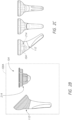
- Figure 2A is a schematic diagram of a total arthroplasty system comprising an arthroplasty kit 100 that can be used to perform anatomic or reverse arthroplasty, or to convert from one of anatomic to reverse or reverse to anatomic arthroplasty, according to various embodiments.
- the kit 100 can comprise one or a plurality of stemless humeral anchors 103, one or a plurality of stemmed humeral anchors 113, and one or a plurality of articular components 161.
- the kit 100 can include a plurality of bowl-shaped stemless humeral anchors 104 with finned distal portions.
- the stemless humeral anchors 104 can have a tapered profile in which a distal portion 105 of the anchor 104 tapers significantly compared with a proximal portion 107 of the anchor 104, such that the distal portion 105 is significantly laterally or radially narrower than the proximal portion 107.
- the relatively narrow distal portion 105 of the anchor 104 can beneficially preserve humeral bone volume by occupying less space within the humerus.
- the kit 100 may additionally, or alternatively, include a plurality of bowl-shaped stemless humeral anchors 108.
- the distal portion 105 of the bowl-shaped humeral anchors 108 may have a smaller taper as compared with the humeral anchors 104.
- the larger distal portion 105 of the humeral anchors 108 can serve a bone-filling function.
- a more voluminous distal portion 105 occupies more of the bone volume distal the humeral resection. This can be beneficial for example when the bone quality toward the center of the metaphysis would not sufficiently support the more tapered anchor 104 but the bone quality toward the cortical portion would sufficiently support the anchor 108.
- the stemless anchors 103 can be provided in a plurality of sizes to accommodate patients of different sizes, different degrees of bone damage to the humerus, etc.
- the lateral size of the stemless anchors 103 may vary so as to fit within different-sized resections of the humerus.
- a length I 1 of the stemless anchors 103 may also vary so as to extend into the humerus by a depth that the clinician selects based on the particular patient being treated.
- the kit 100 can also include one or a plurality of stemmed humeral anchors 113.
- the kit 100 can include one or more humeral stem anchors 112, each of which includes a proximal metaphysis portion 120 and an elongate diaphysis portion ( e.g ., stem portion) 116 extending therefrom.
- the kit 100 can also include a trauma or fracture stem anchor 140, which can be used in patients that have experienced a fracture of the humerus H.
- the stemmed humeral anchors 113 may be used in patients in which stemless anchors 103 may not be adequately secured to the humerus, for example, in patients that have experienced severe bone loss.
- the kit 100 can include stemmed anchors 113 having a plurality of different sizes, e.g. , different lateral sizes and/or different lengths I 2 .
- the stemmed humeral anchors 113 can have respective lengths I 2 that are longer than the lengths I 1 of the stemless anchors 103.
- the lengths I 2 of the stemmed humeral anchors can be in a range of 55 mm to 125 mm.
- the shorter lengths I 1 of the stemless humeral anchors 103 can be in a range of 16 mm to 28 mm.
- stemmed humeral anchors 113, 140 can be configured to reach into the intramedullary canal of the humerus H for additional anchorage.
- the kit 100 can comprise one or a plurality of shared humeral components that be used with either the stemless humeral implants 103 or the stemmed humeral implants 113, depending on which implant 103 or 113 would be more appropriate for a particular patient's humeral anatomy.
- the shared humeral components of the kit 100 can comprise a plurality of inserts 161 that can be used in conjunction with either the stemless implants 103 or the stemmed implants 113.
- the kit 100 can include an anatomic articular component 160 configured to mechanically couple to both the stemless humeral implants 103 and the stemmed humeral implants 113.
- the clinician may select the anatomic articular component 160 for procedures in which an anatomic reconstruction is suitable.
- the anatomic articular component 160 can comprise a coupler 168 and an articular body 164 (anatomical) configured to mechanically engage the coupler 168.
- the articular body 164 for the anatomic articular component 160 can comprise a rounded, convex surface configured to engage a glenoid surface of the patient.
- the coupler 168 can serve to mechanically connect the anatomical articular body 164 (e.g ., a rounded or essentially spherical surface) to either a stemmed humeral implant 103 or a stemmed humeral implant 113, depending on the patient's humeral bone structure.
- the articular body 164 and the coupler 168 can comprise a metal, such as cobalt, chrome, or titanium.
- the articular body comprises a pyrocarbon layer on at least the articular surface.
- the kit 100 can include anatomic articular components 160 having a plurality of sizes.
- the kit 100 can also include a reverse articular component 180 configured to mechanically couple to both the stemless humeral implants 103 and the stemmed humeral implants 113.
- the clinician may select the reverse articular component 180 for procedures in which a reverse anatomic reconstruction is suitable.
- the reverse articular component 180 can comprise a reverse articular body 184 and a locking device 188 configured to secure the reverse articular component 180 to a stemless humeral implant 103 or a stemmed humeral implant 113, depending on the clinician's recommendation during the procedure.
- the reverse articular body 184 can comprise a rounded concave surface (e.g ., essentially spherical) configured to engage with a glenosphere connected to the glenoid of the patient.
- the kit 100 can include a wear resistant reverse articular component 180A, which may be generally similar to the reverse articular component 180 but may further be formed to include vitamin E to promote long-term compatibility with the patient's bone structure.
- the reverse components 180, 180A can comprise a polymer, including, for example, ultra high molecular weight polyethylene.
- the kit 100 can include reverse articular components 180, 180A having a plurality of sizes.
- the clinician may inspect the bone structure of the humerus and/or the scapula to determine whether the anatomy is suitable for a stemless or stemmed humeral anchor, and whether the anatomy is suitable for an anatomical or reverse anatomical reconstruction.
- the kit 100 shown in Figure 2A can provide the clinician with a total arthroplasty system including components that are compatible with stemless or stemmed anchors, and with anatomical or reverse anatomical constructions.
- the clinician may observe that the patient has sufficient humeral bone structure so that a stemless anchor 103 may be used to reduce the damage to the patient's anatomy.
- the clinician can select a bowl-shaped anchor 104 or 108, and can select the corresponding size appropriate for the patient.
- the clinician may also elect whether to proceed with an anatomical reconstruction or a reverse construction, and can accordingly select either the anatomical articular component 160 or the reverse articular component 180, 180A.
- the clinician determines that the patient's bone structure is damaged or otherwise more suited to a stemmed anchor 113, then the clinician can select an appropriately sized stemmed anchor 113.
- the clinician can further select whether to proceed with an anatomical reconstruction or a reverse construction, and can accordingly select either the anatomical articular component 160 or the reverse articular component 180, 180A.
- the kit 100 of Figure 2A includes interchangeable or interoperable components that can be used in stemmed or stemless anchors, and with anatomical or reverse anatomical reconstructions.
- the clinician can make, or change, reconstruction decisions during surgery.
- the kit 100 can accordingly enable the clinician to quickly determine the reconstruction procedure most suitable for a patient and can provide the clinician with the components to be used for that reconstruction procedure.
- the kit 100 can also include one or more trauma stems 140.
- the coupler 168 can comprise a proximal extension 163A configured to connect to the articular body 164 and a distal extension 163B.
- the distal extension 163B for the fracture stem 140 can be received within a recess 217 of the fracture stem 140 for anatomical reconstructions.
- the disc or middle portion 162 disposed between the proximal extension 163A and the distal extension 163B can be eliminated since the recess 217 is elevated toward the resection plane.
- the recess 217 is recessed from ( e.g ., extends distally from) a distal end of the recess 216, similar to what is shown in FIGS. 7F and 7G .
- the disc or middle portion 162 provides a spacer function in use in the trauma stem 140. Additional details of trauma stems may be found throughout International Application No. PCT/US2015/065126, filed December 15, 2015 .
- Figure 2B is a schematic diagram of a total arthroplasty system comprising an arthroplasty kit 100A that can be used to perform anatomic or reverse arthroplasty, or to convert from one of anatomic to reverse or reverse to anatomic arthroplasty, according to another embodiment.
- Figure 2C is a schematic view showing a stemless humeral anchor 104 visually overlaid with a humeral stem anchor 112 (not physically disposed within the stem anchor 112).
- the components of the kit 100A can be generally similar to like-numbered components of Figure 2A , except reference numerals in Figures 2B and 2C have been appended with the letter "A.”
- the kit 100A can comprise a humeral stem anchor 112 and a stemless humeral anchor 104A.
- an exterior surface 214A of the stemless anchor 104A can occupy or define less volume than the metaphysis portion 120 of the stemmed anchor 112.
- the stemless anchor 104A may be inserted into the metaphyseal portion of the humerus. If the clinician determines that the bone structure is damaged such that the stemless anchor 104A is not adequately secured to the humerus, then the clinician can remove the stemless anchor 104A and insert the stemmed anchor 112A into the humerus. The clinician can enlarge the opening into the humerus to accommodate the wider metaphysis portion 120 of the stemmed anchor 112A.
- the clinician can have the ability to enlarge the resection without compromising the patient's humeral bone structure.
- the proximal end e.g ., the collar, which is described below
- the proximal ends may fit within the same size resection.
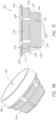
- FIGS 3-4E illustrate stemless anchor 103 comprising a stemless bowl-shaped humeral anchor 108B, according to one embodiment.
- the bowl-shaped humeral anchor 108B can have a distal portion in which at least a portion of the exterior surface has a curved ( e.g ., convex) profile.
- the distal portion of bowl-shaped humeral anchors may be wider than corresponding distal portions of finned humeral anchors.
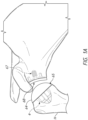
- Figure 3 is a schematic side view of the stemless humeral anchor 108B shown secured within the humerus H , with the humerus H illustrated as semi-transparent for ease of illustration. It should be appreciated that, although Figure 3 shows the stemless anchor 108B, any of the other stemless anchors 103 described herein may be similarly inserted into the humerus H as shown in Figure 3 . As explained herein, in the illustrated embodiment, the anchor 108B may be inserted into the humerus H by non-rotational, direct insertion into the humerus H.
- humeral anchors may be inserted into the humerus H using a rotational motion, for example, to thread, screw, or drill the anchor into the humerus H.
- a rotational motion for example, to thread, screw, or drill the anchor into the humerus H.
- the need to rotate the anchor may complicate the surgical process, such that the clinician must either manually rotate the anchor into position, or use other instruments to rotate the anchor into the humerus H.
- the disclosed embodiments may beneficially enable direct non-rotational insertion into the humerus H to simplify the replacement procedure.
- the stemless anchor 108B can include a collar 244B at a first or proximal end 204B of the anchor 108B.
- the collar 244B may be provided generally flush with the resection surface RS.
- the collar 244B may be provided slightly above the resection surface RS.
- the collar 244B may be provided slightly below the resection surface RS.
- An insert 161 (which is illustrated as a reverse articular component 180 in Figure 3 ) can be inserted into a recess 216B of the stemless anchor 108B.
- the reverse articular component 180 can be configured to engage with a glenoid sphere.
- portions of the recess 216B can be disposed below the resection surface RS.
- Providing portions of the insert 161 (e.g ., portions of the articular body 184, such as portions configured for engaging the recess 216B or even a portion of the concave surface) below the resection surface RS can beneficially improve the surgical reconstruction since the prosthesis may more closely match the natural anatomy of the humerus H.
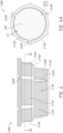
- Figure 4 is a schematic side view of the stemless humeral anchor 108B shown in Figure 3 .
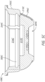
- Figure 4A is a sectional view of the anchor 108B shown with the insert 161 disposed within the anchor 108B of Figure 4 , taken along section 4A-4A.
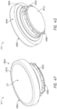
- Figure 4B is a schematic top perspective view of the anchor 108B of Figure 4A .
- Figure 4C is a schematic bottom perspective view of the anchor 108B of Figure 4A .
- Figure 4D is a schematic side sectional view of the anchor 108B of Figure 4A .
- the anchor 108B of Figures 3-4D can have a first end 204B and a second end 208B spaced from the first end 204B.
- the first end 204B can be a proximal end.
- the second end 208B can be a distal end.
- the anchor 108B can comprise a monolithic body.
- the anchor 108B can comprise a wall 213B having an exterior surface 214B facing outwardly from a central portion of the anchor 108B and an interior surface 212B facing inwardly toward the central portion of the anchor 108B.
- the interior surface 212B and the exterior surface 214B can extend between the first and second ends 204B, 208B of the anchor 108B.
- the inner surface 212B can be disposed about a recess 216B disposed between the first and second ends 204B, 208B.
- the recess 216B can be configured to secure a shoulder articular body or component (such as the reverse articular component 180) to the interior surface 212B.
- a collar 244B can be provided at or near the first end 204B.
- the collar 244B can comprise a transverse surface configured to engage a humeral bone layer exposed by resection ( e.g ., at or near the resection surface RS ) or other preparation when the humeral anchor 108B is implanted to resist subsidence.
- the interior surface 212B may comprise one or more tapered surfaces for engaging an articular assembly, such as any of the inserts 161 shown in Figure 2A .
- the interior surface 212B can comprise a first tapered surface 212B' disposed towards the first end 204B and a second tapered surface 212B" disposed towards the second end 208B.
- the first tapered surface 212B' can extend generally between the first end 204B and a shoulder 215B disposed laterally inward from the wall 213B.
- the first tapered surface 212B' can be angled or tapered to receive an insert 161 comprising a shoulder articular body, e.g ., the anatomical articular body 160 or the reverse articular body 180.
- the first tapered surface 212B' can be angled such that the recess 216B is wider at the first end 204B than at locations towards the second end 208B ( e.g ., than at the shoulder 215B).
- the second tapered surface 212B" can be angled or tapered to engage with an adaptor 460 (see Figure 4E ) for coupling the anchor 108B to a stemmed anchor 113.
- the second tapered surface 212B" can extend from the shoulder 215B to the second end 208B.
- the recess 216B can be wider (or can be approximately the same width) at the second end 208B than at the shoulder 215B. In other embodiments, the recess 216B can be wider at or near the shoulder 215B than at the second end 208B.
- the interior surface 212B can comprise one or a plurality of slots 264B sized and configured to engage an insert 161 (such as the articular components 160, 180).
- the slots 264B can engage or receive corresponding ridges 189A, 191A of the insert 161 (see, for example, Figure 4J ).
- the slots 264B can limit rotation of the insert 161 relative to the anchor 108B.
- the slots 264B can also guide the advancement of the insert 161 into an upper portion of the recess 216B.
- the slots 264B can be disposed vertically along the interior surface 264B and can be circumferentially spaced from one another.
- the slots 264B can extend from a location proximate the first end 204B towards the shoulder 215B.
- the interior surface 212B can comprise a groove 300B extending circumferentially about the recess 216B.
- the groove 300B can be sized and configured to receive a locking ring of an articular body assembly ( e.g ., any of the inserts 161 described herein).
- the exterior surface 214B can comprise a first tapered portion 292B disposed about the first end 204B and a second tapered portion 296B disposed about a portion of the humeral anchor 108B between the first tapered portion 292B and the second end 208B of the anchor 108B.
- the first tapered portion 292B can have a first angle disposed away from a longitudinal axis y extending through the first end 204B to the second end 208B.
- the second tapered portion 296B can have a second angle disposed away from the axis y. In some embodiments, the second angle can be greater than the first angle.
- the first and second tapered portions 292B, 296B can be discontinuous from one another.
- a lateral projection 248B can provide at least a portion of the discontinuity between the tapered portions 292B, 296B.
- the lateral projection 248B can assist in reducing subsidence.
- providing a multiple stage (e.g ., two-stage) taper using the tapered portions 292B, 296B can ease the insertion of the anchor 108B into the humerus H.
- the second tapered portion 296B has a lower profile than the first tapered portion 292B, the second tapered portion can be fit into a smaller space in the resected humerus. Such placement can be achieved with less reaming than were the second tapered portion 296B along the same taper as the first tapered portion 292B.
- the stemless humeral anchor 108B can comprise a porous surface 272B disposed on the exterior surface 214B.
- the porous surface 272B can be configured to foster the growth of bone into the porous surfaces 272B to improve integration of the anchor 108B into the anatomy.
- the porous surfaces 272B can be bounded by one or more non-porous edges 276B that can protect the porous surfaces 272B.
- an upper non-porous edge 276B can separate the porous surfaces 272B that are disposed on the tapered portions 292B, 296B, respectively.
- the upper non-porous edge 276B can be disposed between the porous surface 272B disposed on the tapered portion 292B and the second end 208B.
- a lower non-porous edge 276B can be disposed near the second end 208B.
- the non-porous edges 276B can protect the porous surfaces 272B during insertion of the anchor 108B into the bone.
- the portion of the anchor 108B underlying the non-porous surface 276B also can provide one or both of enhanced strength against load directed transverse thereto.
- the anchor 108B can also include a plurality of struts 304B disposed about or along the exterior surface 212.
- the struts 304B can be disposed vertically or along or generally aligned to the longitudinal axis y and can be disposed on the first tapered portion 292B of the anchor 108B.
- the struts 304B can have an external surface that is tapered as in the first tapered portion 292B.
- the struts 304B can extend from the first end 204B towards the second end 208B between the ends 204B, 208B ( e.g ., from the collar 244B to the lateral projection 248B).
- the struts 304B can be circumferentially spaced from one another with the porous surface 272B being disposed between adjacent struts 304B. There can be several porous surfaces 272B arrayed about the periphery of the first tapered portion 282B, with struts 304B disposed therebetween.
- the struts 304B can beneficially assist in reducing, minimizing, or eliminating rotation of the humeral anchor 108B.
- the struts 304B may be configured to improve the strength of the anchor 108B.
- the anchor 108B can include one or a plurality of fins 306B disposed along the exterior surface 212.
- the fins 306B can be circumferentially spaced from one another with the porous surface 272B intervening between adjacent fins 306B.
- the fins 306B can extend from the lateral projection 248B towards the second end 208B.
- the fins 306B can be angled so as to be thicker near the lateral projection 248B and thinner nearer the second end 208B.
- the fins 306B can beneficially assist in reducing rotation of the anchor 108B.
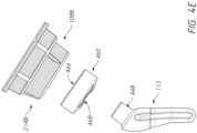
- Figure 4E illustrates an exploded view that shows the stemless anchor 108B configured to connect to an adaptor 460 for coupling to a stemmed anchor 113, 140.
- the adaptor 460 can comprise a first opening 466 at a first end and a second opening 468 at a second end.
- the second end 208B of the anchor 108B can be disposed around the outer periphery of the adaptor 460 to couple with the adaptor 460.
- the second opening 468 can be disposed about a joining member 448 (such as a projection or male joining member) of the stemmed anchor 113 to mechanically couple the stemless anchor 108B to the stemmed anchor 113.
- the stemless anchor 108B can be used in both stemless and stemmed reconstructions.
- a stem adaptor and kits including one or more stems, adaptors, and related components may be found throughout International Patent Application No. PCT/US2017/028470, filed on April 19, 2017 .
- the coupler 168 (and hence the articular body 164) may couple to the stemmed anchor to provide an anatomical reconstruction for the fracture stem. Additional details of using a fracture stem with components similar to the coupler 168 may be found throughout International Patent Application No. PCT/U S2015/065126 .
- Figures 4F-4K illustrate an embodiment of an insert 161 comprising a reverse articular component 180A configured to be used in a reverse shoulder prosthesis by coupling to a glenoid sphere or glenosphere.
- Figure 4F is a top perspective view of the reverse articular component 180A.
- Figure 4G is a bottom perspective view of the reverse articular component 180A shown in Figure 4F .
- Figure 4H is a schematic side view of the reverse articular component 180A shown in Figure 4F .
- Figure 4I is a schematic side sectional view of the reverse articular component 180A shown in Figure 4F .
- Figure 4J is a magnified perspective view of a portion of the reverse articular component 180A shown in Figure 4F .
- the reverse articular component 180A can comprise a reverse articular body 184A coupled to or formed with a locking device 188A configured to secure the articular component 180A to either a stemless anchor 103 or a stemmed anchor 113.
- the reverse articular body 184A can comprise a concave surface CV extending distally from a raised rim 187A.
- the concave surface CV can comprise a curved surface, which may be generally spherical and shaped to cooperate with a glenoid sphere coupled to a glenoid surface of the patient.
- at least a portion of the articular body 184A can be disposed below the resection surface RS.
- a connection portion and in some cases, a portion of the concave surface CV can be disposed below the resection surface RS.
- a pedestal portion 181A can extend distally from the upper portion of the articular body 184A.
- the pedestal portion 181A can be narrower than (or have a smaller diameter than) the raised rim 187A.
- a sloped surface 185A can extend between the pedestal portion 181A and a lower portion of the raised rim 187A. The sloped surface 185A can engage with the interior surface of the stemless or stemmed humeral anchors 103, 113 so as to be slidably inserted into a recess of a humeral anchor.
- the locking device 188A can be provided on the pedestal portion 181A and can comprise a snap ring 183A disposed within an outer annular groove 190A of the pedestal portion 181A.
- the pedestal portion 181A can comprise an upper ridge 189A spaced apart from a lower ridge 191A with the outer groove 190A disposed between the ridges 189A, 191A.
- the ridges 189A, 191A can engage and be received within the corresponding slots 264B to limit or prevent rotation of the insert 161 relative to the humeral anchor in which it is received.
- the ridges 189A, 191A can be disposed vertically ( e.g ., extending along the axis y ) and can be circumferentially spaced from one another.
- Figure 4K is a schematic top plan view of the snap ring 183A shown in Figures 4F-4J .
- Figure 4L is a schematic side sectional view of a portion of the snap ring 183A taken along section 4L-4L.
- the snap ring 183A can comprise a partially annular undulating ring.
- the ring 183A can comprise thicker portions 194A alternately disposed between laterally thinner portions 193A.
- the thinner portions 193A can comprise concave outer surfaces
- the thicker portions 194A can comprise convex outer surfaces, such that an inflection point or discontinuity is disposed between the portions 193A, 194A.
- a gap 195A can be disposed between opposing ends of the ring 183A to define the partially annular, undulating structure.
- a thickness t of the ring 183A may be generally constant across its path length in some embodiments.
- the undulating shape of the snap ring 183A can be configured to ensure a relatively constant insertion force upon insertion of the reverse articular body 184A into the anchor 108B across a range of sizes.
- a first humeral anchor 108B can have a recess 216B of a first size.
- a first snap ring 183A can be sized to engage the 300B of the first humeral anchor 108B.
- a second humeral anchor 108B can have a recess 216B of a second size larger than the first size.
- a second snap ring 183A can be sized to engage the 300B of the second humeral anchor 108B.
- the larger size snap ring would be more flexible and would be insertable under a lower force.
- the smaller snap ring would be more rigid and would requires a higher insertion force.
- the larger snap ring would be subject to dislodgement under a lower load than the smaller snap ring.
- the undulating design provides a more uniform insertion force for an insert 161 with a smaller snap ring and for an insert 161 with a larger snap ring.
- the undulating snap ring provides a more consistent dislodgement force for different sizes. This more uniform performance provides more consistency and familiarity among a kit of inserts 161.
- Figures 5A-5C another embodiment of a bowl-shaped stemless humeral anchor 108C is illustrated.
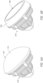
- Figure 5A is a schematic top perspective view of the bowl-shaped stemless humeral anchor 108C.
- Figure 5B is a schematic bottom perspective view of the anchor 108C of Figure 5A .
- Figure 5C is a schematic side sectional view of the anchor 108C of Figure 5A .
- the components of Figures 5A-5C may be the same as or generally similar to like numbered components of Figures 1A-4E , with the reference numerals appended with the letter "C.”
- the anchor 108C can comprise a bowl-shaped anchor.
- the anchor 108C can comprise a monolithic body. Unlike the embodiment of Figures 4-4E , however, the anchor 108C includes a second end portion 208C that is enclosed.
- a lower wall 311 can be provided at the second end portion 208C to enclose the anchor 108C such that bone is not disposed within the anchor 108C.
- the second end 208B comprises an opening. The opening in the second end 208B can be enclosed with a separate component.
- a plurality of second fins 307C can be provided proximal the second end 208B and disposed within a cavity 309C at the second end 208C.
- the fins 307C can be disposed radially outward (for example, in spoke-like fashion) from a central portion and can extend to an inner wall of the cavity 309C.
- the second fins 307C can provide further anti-rotation capabilities for the anchor 108C.
- the cavity 309C can provide space between adjacent fins 307C so as to enable bone ingrowth between the fins 307C.
- the second tapered portion 296C can be tapered at a higher angle as compared with the portion 296B, which can reduce the volume of bone to be removed.
- the tapered portion 296C can have a taper at an angle in a range of 1 to 15 degrees, or in a range of 2 to 10 degrees, e.g., about 5 degrees. This can simplify the procedure and also can preserve bone stock for subsequent procedures.
- the shoulder 215C can extend farther inwardly than the shoulder 215B, so as to define a second cavity 217C disposed below or distal the cavity 216C (also called a first cavity).
- the second cavity 217C can be sized and shaped to receive a portion of coupler 168A configured to enable the anchor 108C to convert from a reverse reconstruction to an anatomical reconstruction.
- a reverse articular component similar to the component 180A may be engaged with the interior surface 212C of the anchor 108C in a manner similar to that described above in connection with Figures 4-4K .
- Figures 5D-5H illustrate an embodiment in which the stemless anchor 108C can be configured for use with an anatomical articular component 160A.
- Figure 5D is a schematic side view of the anatomical articular component 160A connected to the stemless anchor 108C of Figures 5A-5C .
- Figure 5E is a schematic perspective sectional view of the component 160A of Figure 5D .
- Figure 5F is a schematic bottom perspective view of an articular body 164A, according to some embodiments.
- Figure 5G is a schematic top perspective view of a coupler 168A, according to some embodiments.
- Figure 5H is a schematic bottom perspective view of the coupler 168A of Figure 5G .
- components related to the articular component 160A may be the same as or generally similar to like-numbered components of Figure 2A , but appended with the letter "A.”
- the anchor 108C can be used in conjunction with a reverse anatomical articular component 180A, in a manner similar to that explained above.
- the anchor 108C may also be used in conjunction with an anatomical component 160A for use in an anatomical shoulder reconstruction.
- the anatomical articular component 160A can include an articular body 164A and a coupler 168A, which may be generally similar to the articular body 164 and coupler 168 of Figure 2A unless otherwise noted.
- the articular body 164A can comprise a spherical head portion 165 having a convex, generally spherical surface profile.
- the articular body 164A can further include an elongate member 166 extending from the spherical head portion 165.
- the coupler 168A can comprise a proximal surface 167, a distal surface 169, and a hole 163 extending from the proximal surface 167 towards the distal surface 169.
- the hole 163 comprises a through hole but in other embodiments the hole 163 can comprise a blind hole.
- the elongate member 166 of the articular body 164A can be inserted into the hole 163 to connect and align the articular body 164A with the coupler 168A.
- a locking device 188' can be used to connect the coupler 168A to corresponding interior surfaces 212C of the anchor 108C.
- a locking ring (not shown) may be disposed in an outer groove 190 to secure the coupler 168A to the anchor 108C.
- Upper and lower ridges 189, 191 can be used to engage with the corresponding slots of the anchor 108C, and can limit relative rotation between the coupler 168A and the anchor 108C.
- Figures 5I-5J one embodiment of a stemmed humeral anchor 112A is illustrated.
- Figure 5I is a front perspective view of the stemmed humeral anchor 112A, according to one embodiment.
- Figure 5J is a rear perspective view of the stemmed humeral anchor 112A of Figure 5I .
- the components of the stemmed humeral anchor 112A can be the same as or generally similar to the anchor 112 shown in Figure 2A , with the components appended with the letter "A.”
- the anchor 112A can comprise a diaphysis portion 116A (or stem) and a metaphysis portion 120A integrally and monolithically formed with the diaphysis portion 116A.
- the metaphysis portion 120A of the anchor 112A can have interior and exterior surfaces that are generally similar to the anchor 108C described and illustrated above.
- the inserts 161 shown in Figure 2A can be inserted to provide a full arthroplasty system for both reverse and anatomical shoulder replacement procedures, and for both stemless and stemmed reconstructions.
- both the anatomic articular component 160 and the reverse articular component 180 of Figure 2A can be inserted into the diaphysis portion 120A.
- the diaphysis portion 116A or stem can be disposed along a longitudinal axis disposed at an angle L to a planar surface 101 of an end of the metaphysis portion 120A.
- This angle L is sometimes referred to as inclination angle.
- the kit 100 of Figure 2A can comprise stemmed anchors 112A having a plurality of sizes, and a plurality different angles L.
- the stemmed anchors 112A can be disposed at an angle L in a range of 120 degrees to 150 degrees to the planar surface.
- the kit 100 can comprise at least one anchor 112A having an angle L in a range of 130 degrees to 140 degrees, e.g.
- the anchor 112A to be selected by the clinician can be patient-specific.
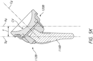
- Figure 5K is a schematic side view of a stemmed anchor 112B having a diaphysis portion 116B (or stem) and a metaphysis portion 120B integrally and monolithically formed with the diaphysis portion 116B.
- the stemmed anchor 112B can be similar to the stemmed anchor provided by assembling the components shown in Figure 4E .
- the metaphysis portion 120B can be configured to interact or support any of the inserts 161 and anchors disclosed herein. In various embodiments, depending on the size of the patient or the extent of bone injury, it may be desirable to provide pre-determined humeral offsets between the humerus H and various portions of the anchor, in order to accommodate different sizes for the implant.
- the stem or diaphysis portion 116B can comprise a longitudinal stem axis S y extending along a longitudinal axis of the diaphysis portion 116B.
- the metaphysis portion 120B can comprise interior surfaces similar to those described above in connection with the stemless anchors described above.
- the diaphysis portion 116B can comprise a concave surface CV and an axis A y passing through a central point on the concave surface CV.
- the diaphysis portion 116B may have a central axis C y passing perpendicular to the concave surface CV.
- a distance between the axes A y and S y can be based on the anatomy of the patient.
- the clinician can select a size of the anchors based at least in part on a distance between an axis of the stem ( S u ) and an axis ( A y ) that intersects the central axis C y of the anchor.
- the clinician can design the stemmed anchor 112B to provide a desired distance between an axis of the stem ( S u ) and an axis ( A y ) that intersects the central axis C y of the anchor.
- the clinician can select an anchor based at least in part on a distance between an axis of the stem ( S u ) and the central lower point of the concave surface (CV) of the device or based on an axis extending through a geometric center of the metaphysis portion 120B and perpendicular to a proximal plane thereof.
- Figures 6A-6F illustrate another embodiment of a stemless humeral anchor 104 configured for use in both anatomical and reverse anatomical shoulder arthroplasty procedures.
- the stemless humeral anchor 104 can comprise the same humeral anchor 104 as that shown in Figures 2A-2B .
- other components of Figures 6A-6F may be the same as or generally ( e.g. , functionally) similar to like-numbered components of Figures 3-5J , but without any letters appending the reference numerals.
- the anchor 104 of Figures 6A-6F can comprise a bowl-shaped stemless anchor with a finned distal portion which can beneficially be used in stemless procedures for reducing or minimizing bone less, as the diameter or width of the distal portion 105 may be less than the diameter or width of the proximal portion 107.
- Figure 6A is a schematic perspective view of a prosthesis comprising the humeral anchor 104 connected to an anatomical articular component 160 comprising an anatomical body 164 with a convex surface.
- the articular component 160 of Figure 6A can be used in an anatomical shoulder replacement procedure.
- the anatomical body 164 can engage with a concave surface coupled to the glenoid surface of the patient.
- Figure 6B is a schematic perspective view of a prosthesis comprising the humeral anchor 104 connected to a reverse articular component 180 comprising a reverse articular body 184 having a concave surface.
- the reverse articular component 180 of Figure 6B can be used in a reverse anatomical shoulder replacement procedure.
- the reverse articular body 184 can engage with a convex surface coupled to the glenoid surface of the patient.
- the anchor 104 can be used in both anatomical and reverse anatomical procedures.
- Figure 6C is a schematic perspective view of the humeral anchor 104 of Figures 6A-6B having a first size.
- Figure 6D is a schematic perspective view of the humeral anchor 104 having a second size different than ( e.g ., smaller than) the first size.
- Figure 6E is a top plan view of the humeral anchor 104 of Figures 6A-6B .
- Figure 6F is a schematic side sectional view of the humeral anchor 104, taken along section 6F-6F.
- the kit 100 can comprise a plurality of the anchors 104 in a corresponding plurality of different sizes.
- the anchor 104 shown in Figures 6C-6D can comprise an exterior surface 114 having a plurality of struts 304, a porous surface 272, one or more non-porous edges 276, and a collar 244, which may function in a generally similar manner to like-numbered components of Figures 3-4E .
- the anchor 104 can comprise a first portion 292 and a second portion 296 at the exterior surface 114.
- the first and second portions 292, 296 may not be tapered ( e.g ., may be generally cylindrical) or may be only slightly tapered.
- the first and second portions 292, 296 can be configured to engage with humeral bone layers upon insertion into the anatomy.
- the anchor 104 may comprise a finned anchor, as opposed to a bowl-shaped anchor 108.
- the lateral projection 248 can position the second portion 296 to be laterally inset from the first portion 292.
- One or a plurality of fins 306 can extend radially outwardly from the second portion 296.
- the fins 306 can be thicker near the lateral projection 248 that at or near the second end 208.
- the fins 306 can serve as anti-rotation features for the anchor 104.
- the anchor 104 can comprise one or more apertures 277.
- the apertures 277 can be used to remove the anchor 104 in the event of problems. For example, if the anchor 104 is to be removed, a tool can be inserted through the aperture(s) 277 to cut soft tissue disposed distal the aperture(s) 277 to assist in freeing the anchor 104 from the humerus H.
- the lateral projection 248 may serve to define a second distal recess 217 that is below or distal to the first recess 116.
- the first recess 216 may be wider and larger than the second recess 217.
- the first recess 216 may be defined by generally cylindrical or only slightly tapered walls.
- the second recess 217 may be defined by generally cylindrical or only slightly tapered walls.
- the second recess 217 can be sized and shaped to receive a portion of the coupler 160 to convert the reverse anatomical reconstruction device of Figure 6B to the anatomical reconstruction device of Figure 6A .
- a tapered surface 260 disposed on the exterior surface 114 can taper the diameter of the anchor 104 such that the diameter or width is smaller at the second end 208 than at the first end 204.
- Figures 7A-7E illustrate another embodiment of a stemless humeral anchor 108 configured for use in both anatomical and reverse anatomical shoulder arthroplasty procedures.
- the stemless humeral anchor 108 can comprise the same humeral anchor 108 as that shown in Figure 2A .
- other components of Figures 7A-7E may be the same as or generally ( e.g. , functionally) similar to like-numbered components of Figures 3-6F , but without any letters appending the reference numerals.
- the anchor 108 of Figures 7A-7E can comprise a bowl-shaped anchor in which the larger distal portion 105 of the humeral anchor 108 can serve a bone-filling function, as explained above.
- Figure 7A is a schematic perspective view of a prosthesis comprising the humeral anchor 108 connected to an anatomical articular component 160 comprising an anatomical body 164 with a convex surface.
- the articular component 160 of Figure 7A can be used in an anatomical shoulder replacement procedure.
- the anatomical body 164 can engage with a concave surface coupled to the glenoid surface of the patient.
- Figure 7B is a schematic perspective view of a prosthesis comprising the humeral anchor 108 connected to a reverse articular component 180 comprising a reverse articular body 184 having a concave surface.
- the reverse articular component 180 of Figure 6B can be used in a reverse anatomical shoulder replacement procedure.
- the reverse articular body 184 can engage with a convex surface coupled to the glenoid surface of the patient.
- the anchor 108 can be used in both anatomical and reverse anatomical procedures.
- Figure 7C is a schematic side view of the humeral anchor 108 of Figures 7A-7B .
- Figure 7D is a schematic top perspective view of the humeral anchor 108 of Figure 7C .
- Figure 7E is a schematic perspective side sectional view of the humeral anchor 108 of Figure 7C .
- the embodiment of Figures 7A-7E can include an exterior surface 114 that includes a plurality of struts 304, a porous surface 272, one or more non-porous edges 276, and a collar 244, which may function in a generally similar manner to like-numbered components of Figures 3-4E .
- the anchor 108 can comprise a first portion 292 and a second portion 296 at the exterior surface 114.
- the first and second portions 292, 296 may not be tapered ( e.g ., may be generally cylindrical) or may be only slightly tapered.
- the first and second portions 292, 296 can be configured to engage with humeral bone layers upon insertion into the anatomy as explained herein.
- a plurality of fins 306 can be disposed along the second portion 296.
- the fins 306 can be spaced circumferentially from one another.
- a plurality of second fins 307 can be disposed at the second end 208.
- the fins 306, 307 can serve to secure the anchor 108 to the bone tissue and to prevent rotation of the anchor 108.
- the second end 208 of the anchor 108 may be closed in some embodiments.
- the interior surface 212 can comprise the apertures 277 the groove 300, and the slots 264, as explained above.
- the anchor 108 can comprise a first recess 216 and a second recess 217 distal or below the first recess 216.
- the first recess 216 can be sized and shaped to receive an insert 161.
- the second recess 217 can be sized and shaped to receive a portion of a coupler 168 for converting the reverse anatomical device of Figure 7B to the anatomical device of Figure 7A .
- the portions 292, 296 may taper inwardly, such that the second end 208 is narrower than the first end 204.
- the second end 208 of the anchor 108 may be larger than the second end 208 of the anchor 104.
- FIGS 7F-7G one embodiment of a stemmed humeral anchor 112 is illustrated.
- the stemmed humeral anchor 112 of Figures 7F-7G may be the same as the stemmed humeral anchor 112 of Figure 2A .
- Figure 7F is a front perspective view of the stemmed humeral anchor 112, according to one embodiment.
- Figure 7G is a rear perspective view of the stemmed humeral anchor 112 of Figure 7F .
- the components of the stemmed humeral anchor 112A can be the same as or generally similar to the anchor 112 shown in Figure 2A , with the components appended with the letter "A.”
- the metaphysis portion 120 of the anchor 112 can have interior and exterior surfaces 112, 114 that are generally similar to the anchor 108 described and illustrated above, which can enable both stemmed and stemless solutions for the kit 100.
- the inserts 161 shown in Figure 2A can be inserted to provide a full arthroplasty system for both reverse and anatomical shoulder replacement procedures, and for both stemless and stemmed reconstructions.
- both the anatomic articular component 160 and the reverse articular component 180 of Figure 2A can be inserted into the diaphysis portion 120.
- the coupler 168 can comprise a bi-surface (e.g., a bi-cone) adaptor having a middle portion 162 and opposing portions or extensions 163A, 163B extending from opposite sides of the middle portion 162.
- the proximal extension 163A can be configured to connect to the articular body 164.
- the distal extension 163B can be configured to be inserted into the second recess 217 of the metaphysis portion 120A.
- the middle portion 162 can be received within the first recess 216.
- coupler 168 Further details of the coupler 168 and other variations of couplers including couplers with expandable disc portions for engaging the surface of the stemmed anchor 112 about the first recess 216 are set forth in U.S. Provisional Patent Application No. 62/740,342, filed on October 2, 2018 , entitled "MODULAR HUMERAL HEAD”.
- the locking device 188 which may comprise a snap ring 183 in some embodiments, can be received within the groove 30 to secure at least a portion of the component 180 within the first recess 216.
- the reverse and anatomical components 160, 180 of Figures 7F and 7G are illustrated with respect to the stemmed anchor 112, it should be appreciated that, as explained above, the same reverse and anatomical components 160, 180 can be used with the stemless anchors 104, 108.
- the stemless humeral anchors 104, 108, 108B, 108C described herein are configured to be able to receive a portion of an articular component 160, 180 below a humeral resection surface RS.
- the anchors described herein are configured to allow a surgeon to reverse the articular surfaces of the shoulder while accommodating soft tissue of a wide variety of patients.
- the humeral anchors 104, 108 108B, 108C enable a surgeon to adapt a patient or a surgical plan from a stemless anchor to a stemmed anchor.
- the stemmed anchor can be adapted to occupy the same or a larger volume of the cancellous bone beneath the resection surface RS.
- the anchors and the couplers described herein can be deployed in other orthopedic applications such as in implanting a glenosphere in a glenoid, a femoral articular body on an end of a femur (e.g., for hip or knee procedures) or for implanting a tibial articular body at an end of a tibia for a joint procedure.
- FIG. 8A illustrates a method 800 for performing a shoulder arthroplasty using the bowl-shaped stemless anchor 104 with finned distal portion described herein in conjunction with the anatomical articular component 160 described herein.
- the method 800 can include a step 801 of resecting a humerus H at a superior or proximal end thereof.
- the resection can be performed with a surgical guide 811 to create a generally planar surface through the humerus H .
- the guide 811 can be a generic guide that is supported on a side surface of the humerus H with rigid pins or bone screws.
- the guide 811 can be a patient specific guide, e.g., any of the patient specific guides disclosed in International Patent Application No.
- the resected surface RS can be protected with a plate member 812.
- the surgeon may be provided with one or more sizing disks 813 to determine a size of the metaphysis in a step 803.
- the sizing disks 813 can be configured to facilitate visualization of the space between the implant to be implanted and the cortical boundary of the bone.
- the sizing disk 813 can also have features that aid in referencing the diaphysis of the humerus H , e.g., one or more apertures for guide pins that assure that the reamed surface (see step 804) in the metaphysis is properly positioned. This is particularly useful if the stemmed anchor 112 is used. Further details of sizing disks 813 and related components to prepare the metaphysis with reference to the diaphysis are discussed in U.S. Provisional Patent Application No. 62/740,257, filed on October 2, 2018 , entitled "METAPHYSEAL REFERENCING TECHNIQUE AND INSTRUMENT".
- the method 800 can include selecting an appropriately sized reamer 814 for the resected humerus H.
- the reamer 814 is configured to produce a generally concave recessed surface S in the resected humerus H.
- the size of the reamer 814 can be selected to correspond to the width of the anchor 104 at or near the first end 204, such that the surface S can accommodate the widest portion of the anchor 104.
- the reamer 814 is guided over a guidewire 819.
- the guidewire 819 can be placed by any suitable technique.
- the sizing disk 813 can be used to assure that the guidewire 819 is in the correct position.
- the resection guide 811 can include or be coupled with a guide device for controlling placement of the guidewire 819. This is discussed in International Patent Application No. PCT/US2018/041531 .
- the method 800 can proceed to a step 805 in which a distal opening DO is drilled using an appropriate drilling tool 815.
- the distal opening DO can be sized and shaped to receive the second end 208 of the anchor 104, which may be smaller than the first end 204.
- the distal opening DO can be further prepared, e.g., blazed with an appropriate blazing tool 816.
- blazing involves forming radial channels that are configured to receive the fins 306 that extent outwardly from the anchor 104. The blazing can be performed only below the first recess 216 to form channels disposed below the first recess 216 in order to accommodate the fine 306.
- the exposed surface(s) of the humerus H can be planarized with a planarizing tool 817.
- an appropriately-sized anchor 104 can be selected for insertion into the prepared resected surface RS of the humerus H.
- components of the anchor or articular body can be inserted into the resected opening(s) of the humerus H in a trial step.
- the proper size anchor 104 can be inserted into the humerus H using a humeral anchor insertion instrument 900 (see also Figures 9A-10D ).
- the anchor 104 can be pushed directly into the humerus H with a non-rotational motion of the anchor 104, e.g ., such that the anchor does not rotate relative to the humerus H as it is being inserted.
- the bone below the resection surface RS is not milled or is only minimally disrupted by the process of inserting the anchor 104. This is consistent with preserving bone stock for future procedures.
- the anatomical articular component 160 can be impacted onto the anchor 104.
- An impactor 818 can be configured to engage the coupler 168 and the articular body 160 with the inserted anchor 104.
- the coupler can be any suitable coupler.
- the impactor 818 can impact the components of the such that the articular body 164 is flush against the resected surface RS of the resected humerus. Further details of the coupler 168 and variations thereof are discussed in U.S. Provisional Patent Application No. 62/740,342, filed on October 2, 2018 , entitled "MODULAR HUMERAL HEAD".
- Figure 8B illustrates a method 850 for performing a shoulder arthroplasty using the bowl-shaped stemless anchor 108 described herein in conjunction with the reverse anatomical articular component 180 described herein.
- Steps 801, 802, and 803 may be the same as or generally similar to like-numbered steps in Figure 8A .
- the reamer 814A may be selected to create a distal opening DO so as to accommodate the bowl-shaped structure of the second end 208 of the anchor 108.
- FIG. 8C is a schematic perspective view of the two-stage reamer 814A attached to a shaft 820, which the clinician can manipulate to engage the humerus H with the reamer 814A, according to some embodiments.
- the reamer 814A can be guided by a humeral guide 826, as shown.
- the guide 826 can include a portion 826A configured to be pinned to a side surface of the humerus H and a removable portion 826B configured to guide the reamer shaft 820 along an outside surface of the shaft thereof.
- the guide 826 can be patient specific in one or more aspects.
- FIG. 8D is a schematic perspective front view of the reamer 814A.
- Figure 8E is a schematic perspective rear view of the reamer 814A.
- the two stage reamer 814A can include a proximal body 821 and a distal body 822 formed with or coupled to the proximal body 821.
- a first plurality of cutting elements 824 can extend radially outward from the distal body 822.
- a second plurality of cutting elements 823 can extend radially outward from the proximal body 821.
- a guidewire lumen 825 can be provided through the reamer 814A, and can be sized and shaped to receive the guidewire 219 described above.
- a lateral dimension (e . g ., width, diameter, etc.) of the proximal body 821 can be larger than a lateral dimension of the distal body 822.
- the proximal body 821 can be wider than the distal body 822.
- the two-stage reamer can be used to define two differently sized openings in the humerus H, for example, to accommodate the varying diameter of the anchor 108.
- the distal body 822 can be configured to create the distal opening DO which receives the finned second portion 296 of the anchor 108.
- the larger proximal body 821 can be configured to create a larger proximal opening PO which receives the first portion 292 of the anchor 108.
- the humeral anchor insertion instrument 900 (which may be the same as or different from the instrument 900 shown in Figure 8A ) may be used to insert an appropriately-sized anchor 108 into the resection surface RS of the humerus H.
- sizers can be used to test the fit of the anchor 108 into the humerus H.
- an impactor 818A can be used to press the reverse articular component 180 onto the anchor 108.
- Figures 9A-9G illustrate an embodiment of a humeral anchor insertion instrument 900 comprising an expansion disc 906.
- the instrument 900 can be configured to reduce or eliminate torque applied to the humeral anchor upon release of the instrument from the anchor.
- Figure 9A is schematic cross-sectional view of a portion of the humeral anchor insertion instrument 900, according to one embodiment.
- Figure 9B is a schematic perspective view of the instrument 900 of Figure 9A .
- Figure 9C is an enlarged, schematic perspective view of a distal portion of the instrument 900 of Figure 9B .
- Figure 9D is a schematic top perspective view of a faceplate 909 for engaging a top, proximal or medial side of the anchor 108C.
- Figure 9E is a bottom perspective view of the faceplate 909 of Figure 9D .
- Figure 9F is a schematic side view of the faceplate 909.
- Figure 9G is a top plan view of an expansion disc 906 of the instrument 900.
- the stemless humeral anchors described herein can be inserted into the humerus H with an insertion motion that does not rotate the humeral anchor. It can be important to provide a secure grip on the humeral anchor during insertion, while ensuring that the anchor can be easily released after insertion without the need for applying excessive torque or other forces. Accordingly, the embodiment of Figures 9A-9G provide improved instrumentation for inserting humeral anchors into the anatomy and for removing the instrumentation from the anchor after insertion. In the illustrated embodiment, the bowl-shaped anchor 108B is shown in an example insertion configuration, but it should be appreciated that the instrument 900 can be used in conjunction with any of the humeral anchors disclosed herein.
- the instrument 900 can comprise a handle 901 that the clinician can grip during insertion and/or release.
- a rod 903 can be disposed within a lumen of the handle 901 and can be translate and rotate relative to the handle 901.
- the rod 903 can be coupled to or formed with a grip 902.
- the clinician can rotate the grip 902 to impart rotation to the rod 903.
- a distal portion of the rod 903 can comprise a tubular threaded portion 904 having internal threads 916B.
- the handle 901 can have a distal portion with external threads 910A configured to threadably engage with corresponding internal threads 910B of the faceplate 909 to mechanically connect the faceplate 909 and the handle 901.
- the faceplate 909 can comprise a central aperture 911 and a cavity 912 sized and shaped to receive the outer dimensions of the handle 901.
- a bolt 905 can extend through the central aperture 911 of the faceplate 909 and into the threaded portion 904 of the rod 903.
- Outer threads 916A of the bolt 905 can threadably engage with inner threads 916B of the threaded portion 904 of the rod 903.
- the distal end of the handle 901 can bear against the upper surface of the faceplate 909.
- the instrument 900 can further comprise an expansion disc 906 configured to expand radially outward and contract radially inward along a radial direction r.
- the expansion disc 906 can comprise a central opening 915, a slot 914 that passes through the central opening 915 and defines an outer gap in the disc 906, and a thinned torsional spring section 913.
- the bolt 905 can further pass through the central opening 915 of the expansion disc 906.
- a head 907 of the bolt 905 can bear against the distal or back surface of the expansion disc 906.
- the faceplate 909 can comprise one or a plurality of lugs 908 extending distally from the faceplate 909.
- the lugs 908 can comprise a thinned portion extending from the faceplate and a wider head at the distal end of the lugs 908.
- the lugs 908 can extend through the slot 914 of the expansion disc 906 with the wider head engaging the back side of the expansion disc 906.
- the expansion disc 906 can be configured to engage the interior surface 212B of the humeral anchor 108B to apply a radially outward gripping force when expanded in a first configuration of the instrument 900 and to disengage from and to not apply a radially outward force on the interior surface 212B of the humeral anchor 108B when in a relaxed or contracted state in a second configuration of the instrument 900.
- the clinician can rotate the grip 902 to impart rotation to the rod 903.
- Rotation of the rod 903 can in turn threadably engage with the bolt 905 to draw the head 907 of the bolt 905 proximally.
- Proximal movement of the bolt 905 can cause the head 907 to bear against the opening 915 to enlargen the slot 914.
- the thinned torsional hinge portion 913 can enable a reduced torque to cause expansion.
- An outermost edge 917 of the expansion disc 906 can engage with the groove 300B of the anchor 108B when the expansion disc 906 is suitably expanded in a radially outward direction.
- the clinician can insert the anchor 108B with a non-rotational insertion motion of the anchor. Once the anchor 108B is secured to the humerus H, the clinician can release the anchor 108B to remove the instrument by rotating the grip 902 in an opposite direction from what was used during insertion. Such a rotational motion can unthread the bolt 905 from the threaded portion 904 of the rod 903 to cause the bolt 905 to move distally. Distal movement of the bolt 905 can cause the expansion disc 906 to relax and the outermost edge 917 to move radially inward from the groove 300B. Once the outermost edge 917 is outside the groove 300B, the instrument 900 can be removed proximally.
- Figures 10A-10D illustrate another embodiment of a humeral anchor insertion instrument 900A configured to reduce or eliminate torque applied to the humeral anchor 108B upon release of the instrument 900A from the anchor 108B.
- Figures 10A-10D are illustrated in conjunction with the anchor 108B, any of the humeral anchors disclosed herein can be used with the instrument 900A.
- Figure 10A is a schematic perspective side sectional view of the instrument 900A.
- Figure 10B is an enlarged schematic side sectional view of a distal portion of the instrument 900A.
- Figure 10C is a side perspective view of a collet 925 of the instrument 900A.
- Figure 10D is a bottom perspective view of the collet 925 of Figure 10C .
- reference numerals in Figures 10A-10D may represent components that are the same as or similar to like-numbered components of Figures 9A-9G , with the reference numerals appended with the letter "A.”
- the instrument 900A can comprise a handle 901, a rod 903A disposed in the handle 901, and a grip 902A configured to impart rotation to the rod 903A.
- a distal portion of the rod 903A can comprise outer threads 916A configured to engage inner threads 916B of the collet 925.
- the collet 925 can comprise a wider proximal portion 927 and a narrower distal portion 926 formed with or coupled to the proximal portion 927.
- the collet 925 can comprise an opening 928 sized and shaped to receive the distal portion of the rod 903A.
- one or more slots 929 can extend in a cross-wise pattern through the distal portion 926 and can intersect with the hole 928.
- one or more anti-rotation recesses 930 can engage with corresponding features on the anchor 108B to limit rotation.
- the collet 925 can be configured to engage an interior surface 212B of the humeral anchor 108B to apply a radially outward gripping force when expanded in a first configuration of the instrument 900A and to disengage from and to not apply a radially outward force on the interior surface 212 of the humeral anchor 108B when in a relaxed or contracted state in a second configuration of the instrument 900A.
- it can be important to securely engage the anchor 108B during insertion of the anchor 108B into the humerus H and to provide an easy release of the instrument 900A from the anchor 108B after insertion.
- the clinician can rotate the grip 902A in a first direction to threadably engage the rod 903A with the threaded portion of the collet 925.
- Distal motion of a tapered surface 931 of the distal end of the rod 903A can engage the opening 928 and slots 929 to cause the collet 925 to expand radially outward.
- Radial outward expansion of the collet 925 can cause an outermost edge 933 of the distal portion 926 of the collet 925 to be disposed within the groove 300B.
- the clinician can insert the anchor 300B into the humerus H with a non-rotatable insertion motion.
- the clinician can release the instrument 900A from the anchor 108B by rotating the grip 902 in a second direction opposite the first used during insertion. Proximal movement of the rod 903A can retract the tapered surface 931 through the opening 928, causing the collet 925 to relax and contract radially. Once the outermost edge 933 is removed from the groove 300B, the clinician can remove the instrument 900A with proximal movement.
- Figures 11A-11C illustrate various components for improving the throughput and quality of manufacturing for the stemless humeral anchors disclosed herein.
- the humeral anchors described herein can be manufactured in any suitable way.
- various additive manufacturing techniques such as three-dimensional (3D) printing
- 3D printing can be very effective at manufacturing complex three-dimensional shapes, including shapes with cavities, grooves, rounded or angled surfaces, etc.
- the throughput of additive manufacturing techniques is generally quite low. Accordingly, it can be desirable to utilize high quality, high throughput manufacturing techniques for the humeral anchors disclosed herein.
- 3D printing may not yield a final article with suitable final dimensions, surface finish or other mechanical properties.
- other manufacturing processes may be combined with 3D printing to obtain a final, finished article.
- Figures 11A-11C are illustrated in connection with the manufacture of an anchor 108B, but the techniques and devices disclosed in Figures 11A-11B can be used for any of the stemless humeral anchors disclosed herein.
- Figure 11A is a schematic perspective view of a blank die 1001 supporting a blank component 1010 prior to a machining process.
- Figure 11B is a schematic side sectional view of the blank die 1001 of Figure 11A.
- Figure 11C is a schematic perspective view of a finished stemless humeral anchor 108B.
- the die 1001 shown in Figures 11A-11B can have an external surface 1014 sized and shaped to have the general contours and tapered surfaces corresponding to complementary interior surfaces 212B of the anchor 108B.
- the external surface 1014 can include an upper tapered portion and a lower tapered portion that may correspond to the inner tapers of the anchor 108B as described herein.
- the blank die 1001 can be formed using an additive manufacturing technique, such as 3D printing.
- the blank die 1001 and the blank component 1010 are both produced in the same additive manufacturing process from an initial layer, e.g., at an outer or proximal end (to the left in Figure 11A ), by adding layers toward the distal end (to the right in FIG. 11A ). As the layers are formed on top of the prior layer the die 1001 and the blank component 1010 are formed together.
- the blank die 1001 can have a notch 1002 at an outer portion of the blank die 1001 so that a manufacturing system (e.g., a computer numerical control, or CNC, machine) can automatically detect the orientation of the blank die 1001 and the blank component 1010 provided over the external surface 1014 of the blank die 1001.
- the notch 1002 also provides an engagement or gripping portion for securing the blank die 1001 in a machining apparatus.
- the blank die 1001 can comprise a central channel 1003 formed along a length of the die 1001 and defined by an inner wall 1012 of the blank die 1001.
- the notch 1002 can be formed in a first handle portion 1006 at the outer end.
- a second handle portion 1006' can be provided at the inner or distal end to improve manipulation of the die 1001 during machining.
- An anti-rotation feature 1005 can be provided at an inner or distal portion of the handle portion 1006' to limit rotation of the die during machining.
- the anti-rotation feature 1005 and the notch 1002 can
- a CNC machine or other automated manufacturing system can be activated to pattern or connect components onto the exterior surface 214B of the anchor 108B.
- the use of the blank die 1001 can cause the blank component 1010 to conform to the general geometry of the anchor 108B to enable the anchor to finished without significant additional processing of the exterior surface.
- Figure 11C illustrates the final anchor 108B produced using the machining techniques disclosed herein.
- the blank die 1001 is formed using additive manufacturing.
- the blank die 1001 is formed such that the external surface 1014 approximates the final exterior surface of the anchor 1008B.
- the external surface 1014 is finished, e.g., using turning, milling or lathing.
- the notch 1002 and the anti-rotation feature 1005 facilitate securing the blank die 1001 in a machining apparatus, e.g. a turning, milling, lathing process, or other similar process.
- the first and second handle portions 1006, 1006' can be removed after the external surface 1014 has been prepared.
- the central channel 1003 can be formed to have generally the same shape and size as the internal surface of the anchor 108B.
- FIG. 11B shows that the central channel 1003 may not have the groove 300B or slots 264B discussed above.
- the anchor 108C has a solid wall 311 enclosing a distal end of the cavity 217C.
- the anchor 108C (and the anchor 108) advantageously are enclosed at the solid wall 311 such that bone matter will be excluded from the interior of the anchor 108C as it is inserted into the humerus bone.
- the die blank 1001 and the blank component 1010 can comprise a pre-formed article for the anchor 108C (and the anchor 108) by forming a solid transverse wall at or near to the junction of the surface 1014 and the handle 1006'. When the handle 1006' is removed, the solid wall 311 can be provided at the inner or distal end of the blank component 1010.
- the solid wall 311 can be perforated in some cases while generally enclosing the distal end of the cavity of the anchor 108C (or the anchor 108).
- the transverse wall at the junction of the surface 1014 and the handle 1006' can be used to define the solid wall 311, and the anchor can be built up layer-by-layer as described above.
- the blank die 1001 can include an elongate stem-shaped profile and, as with the stemless anchors, the stem can be formed along the elongate stem-shaped profile of the die 1001. Still other methods of forming the stemmed anchor may be suitable.
- proximal and distal shall be defined from the perspective of the implant.
- proximal refers to the direction of the articular component
- distal refers to the direction of an anchor component, such as a stem of a humeral anchor or a thread or porous surface or other anchoring structure of a stemless anchor when the implant is assembled.
- a phrase referring to "at least one of' a list of items refers to any combination of those items, including single members.
- "at least one of: A, B, or C” is intended to cover: A, B, C, A and B, A and C, B and C, and A, B, and C.
- Conjunctive language such as the phrase "at least one of X, Y and Z," unless specifically stated otherwise, is otherwise understood with the context as used in general to convey that an item, term, etc. may be at least one of X, Y or Z. Thus, such conjunctive language is not generally intended to imply that certain embodiments require at least one of X, at least one of Y and at least one of Z to each be present.
- any methods disclosed herein need not be performed in the order recited.
- the methods disclosed herein include certain actions taken by a practitioner; however, they can also include any third-party instruction of those actions, either expressly or by implication.
- actions such as “coupling a glenoid guide with the glenoid rim” include “instructing coupling of a glenoid guide with a glenoid rim.”
Landscapes
- Health & Medical Sciences (AREA)
- Transplantation (AREA)
- Orthopedic Medicine & Surgery (AREA)
- Heart & Thoracic Surgery (AREA)
- Cardiology (AREA)
- Oral & Maxillofacial Surgery (AREA)
- Engineering & Computer Science (AREA)
- Biomedical Technology (AREA)
- Vascular Medicine (AREA)
- Life Sciences & Earth Sciences (AREA)
- Animal Behavior & Ethology (AREA)
- General Health & Medical Sciences (AREA)
- Public Health (AREA)
- Veterinary Medicine (AREA)
- Physical Education & Sports Medicine (AREA)
- Prostheses (AREA)
Abstract
Description
- The present invention relates to a humeral anchor. The invention also relates to a kit comprising such a humeral anchor.
- The present application is directed to apparatuses and methods for reverse and anatomic shoulder prostheses.
- Arthroplasty is the standard of care for the treatment of shoulder joint arthritis. A typical anatomical shoulder joint replacement attempts to mimic anatomic conditions. For example, a metallic humeral stem and a humeral head replacement are attached to the humerus of the arm and replace the humeral side of the arthritic shoulder joint. Such humeral head replacement can articulate with the native glenoid socket or with an opposing glenoid resurfacing device.
- For more severe cases of shoulder arthritis, the standard treatment is a reverse reconstruction, which includes reversing the kinematics of the shoulder joint. A reverse shoulder prosthesis can be provided by securing a semi-spherical device (sometimes called a glenoid sphere) to the glenoid and implanting a humeral stem with a cavity capable of receiving the glenoid sphere.
- As patient disease may progress after anatomic treatment, revision surgery may be necessary to perform a reverse reconstruction of the shoulder. In the known art, the change in the type of prosthesis is addressed either below the plane of resection or above the plane of resection. In prosthesis that are converted from anatomic to reverse by a modularity below the plane of resection, removal of anatomic devices that have integrated into the patient's bony anatomy proves to be difficult for the surgeon, and could potentially cause excessive patient bone loss . One advantage of such conversion is that the reverse insert could partially reside below the resection plane and therefore reduce the distance between the cavity and the lateral contour of the humerus. Such position has proven to be beneficial to a reversed kinematics. In contrary, in prosthesis that are converted from anatomic to reversed above the plane of resection thanks to an adaptor, reverse kinematic is altered as the position of the cavity is further push out of the humerus by the addition of the adaptor above the resection plane. Such construct are typically made of three (3) components that present an extra modularity in comparison to a two (2) component construct and could potentially cause disassembly or breakage of the construct. One possibility to limit the alteration of the kinematics and limit the modularity is to inverse the bearing surface material by having a harder cavity within the humerus and a softer semi-spherical device secured to the glenoid. But the proven clinical design and preferred embodiment is usually that the cavity is softer than the semi-spherical device.
- Improved humeral components, assemblies, and methods are needed to provide more flexibility in working with soft tissue around the shoulder joint. Such components may benefit from placement of at least a portion of the humeral anchor below a humerus resection plane. Such components may benefit from placement of at least a portion of the humeral anchor and also at least a locking portion of an articular assembly below a humerus resection plane. An object of the present invention is a humeral anchor as defined in
claim 1. - In one embodiment, a humeral anchor is disclosed. The humeral anchor can include a first end and a second end. The humeral anchor can include an interior surface extending between the first end and the second end, the interior surface disposed about a recess disposed between the first end and the second end. The recess can be configured to secure a coupling of a shoulder articular body directly to the interior surface.
- In some embodiments, a transverse surface can be configured to engage a humeral bone layer exposed by resection or other preparation when the humeral anchor is implanted to resist subsidence. The transverse surface can comprise a portion of a collar disposed at the first end of the humeral anchor. The transverse surface can comprise an anti-rotation feature disposed between the first end and the second end of the humeral anchor. The interior surface can comprise a tapered surface for engaging an articular assembly. The interior surface can be disposed about the interior surface comprises a slot for engaging an articular assembly. An exterior surface having a porous surface can be at least partially bounded by a non-porous edge, the non-porous edge being disposed between the porous surface and the second end. The interior surface can comprise a first taper disposed towards the first end and a second taper disposed towards the second end. An exterior surface having a first tapered portion can be disposed about the first end and a second tapered portion can be disposed about a portion of the humeral anchor between the first tapered portion and the second end of the humeral anchor, the second tapered portion being discontinuous from the first tapered portion. The first tapered portion can have a first angle away from an axis disposed from the first end to the second end and the second tapered portion can have a second angle away from the axis disposed from the first end to the second end, the second angle being greater than the first angle. The interior surface can comprise a groove configured to receive a locking ring of an articular body assembly. In some embodiments, the humeral anchor can include a plurality of struts disposed about an exterior surface of the humeral anchor between the first end and the second end. A porous surface can be disposed between at least two struts of the plurality of struts. A plurality of struts can be disposed about an exterior surface of the humeral anchor. The exterior surface can have a first portion disposed about the first end and a second portion between the first portion and the second end of the humeral anchor, the struts being disposed about the first portion. A first plurality of struts can be disposed about the first portion and at least one strut is disposed about the second portion. The first plurality of struts can have twice as many struts as the second plurality of struts. The struts can be disposed about the second portion. The struts can be configured to reduce, minimize or eliminate rotation of the humeral anchor.
- In some embodiments, a kit can include a first humeral comprising a first humeral anchor exterior surface and a first collar disposed at the first end thereof. The kit can include a second humeral anchor comprising a second humeral anchor exterior surface and a second collar disposed at the first end thereof. The first humeral anchor and the second humeral anchor can have identical interior surfaces. The first collar and the second collar can have the same outer perimeter dimensions. The second humeral anchor exterior surface can be larger than the first humeral anchor exterior surface.
- In some embodiments, the humeral anchor can have at least one fin configured to reduce, minimize or eliminate rotation of the humeral anchor when the humeral anchor is implanted in bone of a humerus. The fin can be disposed at the second end of the humeral anchor. In some embodiments, an array of fins can be disposed radially at the second end of the humeral anchor.
- In some embodiments, a stemmed anchor can include the humeral anchor and a stem coupled with and extending from the second end of the humeral anchor. In some embodiments, a kit can include the humeral anchor configured as a stemless anchor and the stemmed anchor. The humeral anchor portion of the stemmed anchor and the stemless humeral anchor can be identical. The first end can comprise a planar surface and the stem can be disposed along a longitudinal axis, the longitudinal axis being disposed at an angle of 135 degrees to the planar surface. The first end can comprise a planar surface and the stem is can be disposed along a longitudinal axis, the longitudinal axis being disposed at an angle of 145 degrees to the planar surface. In some embodiments, an angle between a planar surface and a longitudinal axis of the stem is patient specific. In some embodiments, a ratio between a diameter of the first end of the humeral anchor and a distal diameter of the stem is patient specific. The distance between a longitudinal axis of the humeral anchor and a longitudinal axis of the stem can be patient specific.
- In some embodiments, a humeral implant assembly is disclosed. The humeral implant assembly can comprise the humeral anchor and an articular assembly comprising an articular body and a locking component. The articular body can comprise at least one strut configured to engage at least one slot disposed in the interior surface of the humeral anchor. The at least one strut can comprise a first portion and a second portion, the locking component extending between the first and second portions of the strut. The locking component can comprise an undulating ring.
- In some embodiments, a kit can comprise a first assembly having a first humeral anchor having a first interior surface with a first interior surface circumference adjacent to the first end thereof. The kit can include a second assembly having a second humeral anchor having a second interior surface with a second interior surface circumference adjacent to the first end thereof. The locking component of the first assembly and the locking component of the second assembly can be configured to provide uniform insertion force during advancement of articular assembly into respective humeral anchor.
- In some embodiments, the recess is a first recess and the humeral anchor further comprises a second recess disposed between the first recess and the second end, wherein the second recess is configured to receive a coupler secured to or adapted to be secured to an anatomical articular body. The humeral anchor can include an exterior surface comprising a first cylindrical portion disposed about the first recess and a second cylindrical portion disposed about the second recess, and a plurality of rotation control features extending radially from the second cylindrical portion to the second end of the humeral anchor. The rotation control features can comprise fins extending radially outwardly from a central portion of the anchor. The second cylindrical portion can comprise an outer wall having a radius less than an inner radius of the first recess.
- In some embodiments, a kit can include a humeral anchor comprising a stem and metaphysis portion having a metaphyseal profile and a stemless humeral anchor comprising an exterior surface. The exterior surface of the stemless humeral anchor can be configured to occupy less volume of a metaphysis of a patient than is the metaphyseal profile of the humeral anchor comprising the stem. The humeral anchor can comprise an exterior surface having a first cylindrical portion disposed around a first recess and a second portion disposed around a second recess.
- In some embodiments, a humeral anchor insertion instrument can include an elongate shaft having a first end and a second end and a handle disposed at the first end of the elongate shaft. An expandable grip can be disposed at the second end of the elongate shaft. The handle can be configured to actuate the expandable grip to a first configuration to apply a radially outward force to an interior surface of a humeral anchor and to a second configuration to separate the expandable grip from the interior surface of the humeral anchor.
- In some embodiments, the expandable grip can comprise an expansion disc having a peripheral surface configured to engage the interior surface of the humeral anchor and a slot configured to receive a wedge member to enlarge the peripheral surface in the first configuration. The expandable grip comprises a split collet in some embodiments.
- In some embodiments, a method of manufacturing a joint anchor is disclosed. The method can include forming a blank component and at least one handle portion coupled to the blank component, the blank component having a shape configured to couple with a shoulder joint articular body. The method can include machining an exterior surface of the blank component to define exterior surface features of the joint anchor. The method can include removing the at least one handle portion.
- In some embodiments, forming the blank component comprises using a three-dimensional (3D) printing technique to form the blank component.
- These and other features, aspects and advantages are described below with reference to the drawings, which are intended for illustrative purposes and should in no way be interpreted as limiting the scope of the embodiments. Furthermore, various features of different disclosed embodiments can be combined to form additional embodiments, which are part of this disclosure. In the drawings, like reference characters denote corresponding features consistently throughout similar embodiments. The following is a brief description of each of the drawings.
-
Figure 1A shows an anatomic total shoulder arthroplasty system disposed in the humerus and the glenoid of a shoulder; -
Figure 1B shows a humeral implant assembly of the total shoulder system shown inFigure 1A ; -
Figure 2A is a schematic diagram of a total arthroplasty system comprising an arthroplasty kit that can be used to perform anatomic or reverse arthroplasty, or to convert from one of anatomic to reverse or reverse to anatomic arthroplasty, according to various embodiments; -
Figure 2B is a schematic diagram of a total arthroplasty system comprising an arthroplasty kit that can be used to perform anatomic or reverse arthroplasty, or to convert from one of anatomic to reverse or reverse to anatomic arthroplasty, according to another embodiment; -
Figure 2C is a schematic view showing a stemless humeral anchor overlaid with a stemmed humeral anchor; -
Figure 3 shows an exploded view of one embodiment of a stemless reverse humeral implant assembly; -
Figure 4 is a side view of the stemless humeral assembly ofFIG. 3 ; -
Figure 4A is a cross-sectional view of the stemless humeral assembly ofFigure 3 , the section taken at theplane 4A-4A; -
Figure 4B is a schematic top perspective view of the assembly ofFigure 4A ; -
Figure 4C is a schematic bottom perspective view of the assembly ofFigure 4A ; -
Figure 4D is a schematic side sectional view of the assembly ofFigure 4A ; -
Figure 4E illustrates an exploded view that shows the stemless anchor ofFigure 4A configured to connect to an adaptor for coupling to a stemmed anchor; -
Figure 4F is a top perspective view of the reverse articular component; -
Figure 4G is a bottom perspective view of the reverse articular component shown inFigure 4F ; -
Figure 4H is a schematic side view of the reverse articular component shown inFigure 4F ; -
Figure 4I is a schematic side sectional view of the reverse articular component shown inFigure 4F ; -
Figure 4J is a magnified perspective view of a portion of the reverse articular component shown inFigure 4F ; -
Figure 4K is a schematic top plan view of a snap ring shown inFigures 4F-4J ; -
Figure 4L is a schematic side sectional view of a portion of the snap ring taken alongsection 4L-4L; -
Figure 5A is a schematic top perspective view of a bowl-shaped stemless humeral anchor, according to another embodiment; -
Figure 5B is a schematic bottom perspective view of the anchor ofFigure 5A ; -
Figure 5C is a schematic side sectional view of the anchor ofFigure 5A ; -
Figure 5D is a schematic side view of the anatomical articular component connected to the stemless anchor ofFigures 5A-5C ; -
Figure 5E is a schematic perspective sectional view of the component ofFigure 5D ; -
Figure 5F is a schematic bottom perspective view of an articular body, according to some embodiments; -
Figure 5G is a schematic top perspective view of a coupler, according to some embodiments; -
Figure 5H is a schematic bottom perspective view of the coupler ofFigure 5G ; -
Figure 5I is a front perspective view of a stemmed humeral anchor, according to one embodiment; -
Figure 5J is a rear perspective view of the stemmed humeral anchor ofFigure 5I ; -
Figure 5K is a schematic side view of a stemmed anchor having a diaphysis portion and a metaphysis portion integrally and monolithically formed with the diaphysis portion; -
Figure 6A is a schematic perspective view of a prosthesis comprising the humeral anchor ofFigure 2A connected to an anatomical articular component; -
Figure 6B is a schematic perspective view of a prosthesis comprising the humeral anchor ofFigure 6A connected to a reverse articular component; -
Figure 6C is a schematic perspective view of the humeral anchor ofFigures 6A-6B having a first size; -
Figure 6D is a schematic perspective view of the humeral anchor having a second size different than the first size; -
Figure 6E is a top plan view of the humeral anchor ofFigures 6A-6B ; -
Figure 6F is a schematic side sectional view of the humeral anchor, taken alongsection 6F-6F; -
Figure 7A is a schematic perspective view of a prosthesis comprising the bowl-shaped humeral anchor ofFigure 2A connected to an anatomical articular component; -
Figure 7B is a schematic perspective view of a prosthesis comprising the bowl-shaped humeral anchor ofFigure 7A connected to a reverse articular component; -
Figure 7C is a schematic side view of the humeral anchor ofFigures 7A-7B ; -
Figure 7D is a schematic top perspective view of the humeral anchor ofFigure 7C ; -
Figure 7E is a schematic perspective side sectional view of the humeral anchor ofFigure 7C ; -
Figure 7F is a front perspective view of a stemmed humeral anchor, according to one embodiment; -
Figure 7G is a rear perspective view of the stemmed humeral anchor ofFigure 7F ; -
Figure 8A illustrates a method for performing a shoulder arthroplasty using a stemless anchor described herein in conjunction with an anatomical articular component; -
Figure 8B illustrates a method for performing a shoulder arthroplasty using a bowl-shaped stemless anchor in conjunction with a reverse anatomical articular component, according to another embodiment; -
Figure 8C is a schematic perspective view of a two-stage reamer guided by a patient specific humeral guide, according to some embodiments; -
Figure 8D is a schematic perspective front view of the reamer ofFigure 8C ; -
Figure 8E is a schematic perspective rear view of the reamer ofFigure 8C ; -
Figure 9A is schematic cross-sectional view of a portion of a humeral anchor insertion instrument, according to one embodiment; -
Figure 9B is a schematic perspective view of the instrument ofFigure 9A ; -
Figure 9C is an enlarged, schematic perspective view of a distal portion of the instrument ofFigure 9B ; -
Figure 9D is a schematic top perspective view of a faceplate for engaging a top, proximal or medial side of the humeral anchor; -
Figure 9E is a bottom perspective view of the faceplate ofFigure 9D ; -
Figure 9F is a schematic side view of the faceplate; -
Figure 9G is a top plan view of anexpansion disc 906 of the instrument shown inFigures 9A-9C ; -
Figure 10A is a schematic perspective side sectional view of a humeral anchor insertion instrument, according to another embodiment; -
Figure 10B is an enlarged schematic side sectional view of a distal portion of the instrument ofFigure 10A ; -
Figure 10C is a side perspective view of a collet of the instrument ofFigure 10A ; -
Figure 10D is a bottom perspective view of the collet ofFigure 10C ; -
Figure 11A is a schematic perspective view of a blank die supporting a blank component prior to a machining process; -
Figure 11B is a schematic side sectional view of the blank die ofFigure 11A ; and -
Figure 11C is a schematic perspective view of a finished stemless humeral anchor using the devices ofFigures 11A-11B . -
Figures 1A and1B show two conventional approaches to total shoulder arthroplasty.Figure 1A shows an anatomic approach in which the humeral head is replaced with anarticular body 64 having an convexarticular surface 65. The glenoid of the scapula can be modified with animplant 67 providing aconcave surface 68 for articulation of the humeralarticular body 64 The humeralarticular body 64 is secured to the humerus H using astemless anchor 4 that is dedicated for and only compatible with the anatomicarticular body 64. -
Figure 1B shows a reverse approach in which the humerus H is fitted with anarticular body 84 having a concavearticular surface 85. The glenoid region of the scapula is fitted with a spherical articular body, commonly called aglenosphere 87. In this case, the concavearticular surface 85 placed on the humerus articulates of theglenosphere 87, which is fixed relative to the scapula. The reversearticular body 84 is mounted to a tray 88 that is disposed between the reverse humeralarticular body 84 and astem anchor 83 that is surgically implanted in the humerus H. The humerus H is prepared by providing access to the medullary canal of the humerus H. - One can see that the anatomic and reverse approaches generally use different hardware to secure the articular components. So, switching from an anatomic to a reverse configuration requires extraction of the
stemless anchor 4. The bone stock that remains after such an extraction may or may not be suitable for supporting thestem anchor 83. Also, the presence of the tray 88 requires more of the joint space. Thus, the reverse configuration may only be suitable for some patients with large joint space or following more invasive preparation of the humerus and/or the scapula. - Various embodiments disclosed herein relate to shoulder prosthesis assemblies that can beneficially lead to improved patient outcomes, for example, by reducing the volume of bone removed from the patient's humerus, reducing surgery time, improving convertability between anatomical and reverse prostheses, providing adaptability with stemmed anchors, and improving reliability of the prosthesis. In some conventional shoulder arthroplasty techniques, a humeral stem anchor may be inserted into the patient's humerus and can be configured to engage with an articular body attached to the glenoid surface. Such a stemmed anchor may present long-term fixation issues, as well as undesirable radiologic signatures such as radiolucencies, spot welds, etc. To reduce fixation problems, radiologic signatures, and surgery times associated with traditional stemmed anchors, stemless anchors can be used.
- Indeed, stemless shoulder arthroplasty has become much more attractive to surgeons for a number of reasons, including shorter surgery time, less blood loss, fewer periprosthetic fractures, easier anatomic reconstructions, etc. Stemless shoulder arthroplasty has been largely limited to use in anatomic reconstructions, such that reverse reconstructions can be challenging. Moreover, providing a stemless reverse reconstruction may not be as bone conserving as anatomic reconstructions. Further, it may be challenging to insert stemless anchors in the anatomy in a way that adequately or easily secures the stemless anchor to the humerus. For example, some stemless anchors may be twisted or threaded into the anatomy.
- Beneficially, various embodiments disclosed herein disclose a reverse arthroplasty stemless device that can preserve as much bone volume as similar stemmed devices. Moreover, the reverse arthroplasty stemless devices disclosed herein can be converted to anatomical devices in some embodiments. In various embodiments, the stemless devices can be incorporated into one or more kits that include stemmed anchors, so that the clinician can select the appropriate prosthesis (e.g., stemmed or stemless) in the operating room after observing the patient's degree of humeral damage.
-
Figure 2A is a schematic diagram of a total arthroplasty system comprising anarthroplasty kit 100 that can be used to perform anatomic or reverse arthroplasty, or to convert from one of anatomic to reverse or reverse to anatomic arthroplasty, according to various embodiments. Thekit 100 can comprise one or a plurality of stemlesshumeral anchors 103, one or a plurality of stemmedhumeral anchors 113, and one or a plurality ofarticular components 161. For example, thekit 100 can include a plurality of bowl-shaped stemlesshumeral anchors 104 with finned distal portions. As explained herein, the stemlesshumeral anchors 104 can have a tapered profile in which adistal portion 105 of theanchor 104 tapers significantly compared with aproximal portion 107 of theanchor 104, such that thedistal portion 105 is significantly laterally or radially narrower than theproximal portion 107. The relatively narrowdistal portion 105 of theanchor 104 can beneficially preserve humeral bone volume by occupying less space within the humerus. Thekit 100 may additionally, or alternatively, include a plurality of bowl-shaped stemless humeral anchors 108. Thedistal portion 105 of the bowl-shapedhumeral anchors 108 may have a smaller taper as compared with the humeral anchors 104. The largerdistal portion 105 of thehumeral anchors 108 can serve a bone-filling function. A more voluminousdistal portion 105 occupies more of the bone volume distal the humeral resection. This can be beneficial for example when the bone quality toward the center of the metaphysis would not sufficiently support the moretapered anchor 104 but the bone quality toward the cortical portion would sufficiently support theanchor 108. - As shown in
Figure 2A , the stemless anchors 103 can be provided in a plurality of sizes to accommodate patients of different sizes, different degrees of bone damage to the humerus, etc. In some embodiments, the lateral size of the stemless anchors 103 may vary so as to fit within different-sized resections of the humerus. In some embodiments, a length I1 of the stemless anchors 103 may also vary so as to extend into the humerus by a depth that the clinician selects based on the particular patient being treated. - The
kit 100 can also include one or a plurality of stemmedhumeral anchors 113. Thekit 100 can include one or more humeral stem anchors 112, each of which includes aproximal metaphysis portion 120 and an elongate diaphysis portion (e.g., stem portion) 116 extending therefrom. In some embodiments, thekit 100 can also include a trauma orfracture stem anchor 140, which can be used in patients that have experienced a fracture of the humerus H. The stemmedhumeral anchors 113 may be used in patients in which stemless anchors 103 may not be adequately secured to the humerus, for example, in patients that have experienced severe bone loss. As with the stemless anchors 103, thekit 100 can include stemmedanchors 113 having a plurality of different sizes, e.g., different lateral sizes and/or different lengths I2 . For example, as shown inFigure 2A , the stemmedhumeral anchors 113 can have respective lengths I2 that are longer than the lengths I1 of the stemless anchors 103. In various embodiments, the lengths I2 of the stemmed humeral anchors can be in a range of 55 mm to 125 mm. By contrast, the shorter lengths I1 of the stemlesshumeral anchors 103 can be in a range of 16 mm to 28 mm. In various embodiments, stemmedhumeral anchors - Beneficially, the
kit 100 can comprise one or a plurality of shared humeral components that be used with either the stemlesshumeral implants 103 or the stemmedhumeral implants 113, depending on which implant 103 or 113 would be more appropriate for a particular patient's humeral anatomy. For example, the shared humeral components of thekit 100 can comprise a plurality ofinserts 161 that can be used in conjunction with either thestemless implants 103 or the stemmedimplants 113. - For example, the
kit 100 can include an anatomicarticular component 160 configured to mechanically couple to both the stemlesshumeral implants 103 and the stemmedhumeral implants 113. The clinician may select the anatomicarticular component 160 for procedures in which an anatomic reconstruction is suitable. The anatomicarticular component 160 can comprise acoupler 168 and an articular body 164 (anatomical) configured to mechanically engage thecoupler 168. As shown inFigure 2A , thearticular body 164 for the anatomicarticular component 160 can comprise a rounded, convex surface configured to engage a glenoid surface of the patient. As explained herein, thecoupler 168 can serve to mechanically connect the anatomical articular body 164 (e.g., a rounded or essentially spherical surface) to either a stemmedhumeral implant 103 or a stemmedhumeral implant 113, depending on the patient's humeral bone structure. Thearticular body 164 and thecoupler 168 can comprise a metal, such as cobalt, chrome, or titanium. In some embodiments, the articular body comprises a pyrocarbon layer on at least the articular surface. In various embodiments, thekit 100 can include anatomicarticular components 160 having a plurality of sizes. - The
kit 100 can also include a reversearticular component 180 configured to mechanically couple to both the stemlesshumeral implants 103 and the stemmedhumeral implants 113. The clinician may select the reversearticular component 180 for procedures in which a reverse anatomic reconstruction is suitable. The reversearticular component 180 can comprise a reversearticular body 184 and alocking device 188 configured to secure the reversearticular component 180 to a stemlesshumeral implant 103 or a stemmedhumeral implant 113, depending on the clinician's recommendation during the procedure. As shown, the reversearticular body 184 can comprise a rounded concave surface (e.g., essentially spherical) configured to engage with a glenosphere connected to the glenoid of the patient. In addition, in some embodiments, thekit 100 can include a wear resistant reversearticular component 180A, which may be generally similar to the reversearticular component 180 but may further be formed to include vitamin E to promote long-term compatibility with the patient's bone structure. Thereverse components kit 100 can include reversearticular components - During an arthroplasty procedure, the clinician may inspect the bone structure of the humerus and/or the scapula to determine whether the anatomy is suitable for a stemless or stemmed humeral anchor, and whether the anatomy is suitable for an anatomical or reverse anatomical reconstruction. Beneficially, the
kit 100 shown inFigure 2A can provide the clinician with a total arthroplasty system including components that are compatible with stemless or stemmed anchors, and with anatomical or reverse anatomical constructions. For example, during a procedure, the clinician may observe that the patient has sufficient humeral bone structure so that astemless anchor 103 may be used to reduce the damage to the patient's anatomy. The clinician can select a bowl-shapedanchor articular component 160 or the reversearticular component - Similarly, if during a shoulder arthroplasty procedure, the clinician determines that the patient's bone structure is damaged or otherwise more suited to a stemmed
anchor 113, then the clinician can select an appropriately sized stemmedanchor 113. The clinician can further select whether to proceed with an anatomical reconstruction or a reverse construction, and can accordingly select either the anatomicalarticular component 160 or the reversearticular component kit 100 ofFigure 2A includes interchangeable or interoperable components that can be used in stemmed or stemless anchors, and with anatomical or reverse anatomical reconstructions. Because the shared humeral inserts 161 (e.g., anatomical or reverse anatomical articular bodies) can be used with either the stemless or stemmedanchors kit 100 can accordingly enable the clinician to quickly determine the reconstruction procedure most suitable for a patient and can provide the clinician with the components to be used for that reconstruction procedure. - As explained above, for humeral fractures, the
kit 100 can also include one or more trauma stems 140. As explained herein in connection withFigures 7F-7G , thecoupler 168 can comprise aproximal extension 163A configured to connect to thearticular body 164 and adistal extension 163B. Thedistal extension 163B for thefracture stem 140 can be received within arecess 217 of thefracture stem 140 for anatomical reconstructions. The disc ormiddle portion 162 disposed between theproximal extension 163A and thedistal extension 163B can be eliminated since therecess 217 is elevated toward the resection plane. In a modified embodiment, therecess 217 is recessed from (e.g., extends distally from) a distal end of therecess 216, similar to what is shown inFIGS. 7F and 7G . In those embodiments, the disc ormiddle portion 162 provides a spacer function in use in thetrauma stem 140. Additional details of trauma stems may be found throughout International Application No.PCT/US2015/065126, filed December 15, 2015 . -
Figure 2B is a schematic diagram of a total arthroplasty system comprising anarthroplasty kit 100A that can be used to perform anatomic or reverse arthroplasty, or to convert from one of anatomic to reverse or reverse to anatomic arthroplasty, according to another embodiment.Figure 2C is a schematic view showing a stemlesshumeral anchor 104 visually overlaid with a humeral stem anchor 112 (not physically disposed within the stem anchor 112). Unless otherwise noted, the components of thekit 100A can be generally similar to like-numbered components ofFigure 2A , except reference numerals inFigures 2B and 2C have been appended with the letter "A." As shown in Figure 100A, thekit 100A can comprise ahumeral stem anchor 112 and a stemless humeral anchor 104A. As shown in the overlay ofFigure 2C , an exterior surface 214A of the stemless anchor 104A can occupy or define less volume than themetaphysis portion 120 of the stemmedanchor 112. - Accordingly, during a procedure, the stemless anchor 104A may be inserted into the metaphyseal portion of the humerus. If the clinician determines that the bone structure is damaged such that the stemless anchor 104A is not adequately secured to the humerus, then the clinician can remove the stemless anchor 104A and insert the stemmed
anchor 112A into the humerus. The clinician can enlarge the opening into the humerus to accommodate thewider metaphysis portion 120 of the stemmedanchor 112A. Beneficially, because the exterior surface 214A of the stemless anchor 104A occupies a relatively small volume (e.g., less volume of the metaphyseal profile of the humerus than themetaphysis portion 120 occupies), the clinician can have the ability to enlarge the resection without compromising the patient's humeral bone structure. It should be appreciated that, although themetaphysis portion 120 of thestem anchor 112A is wider than the finned portion of the stemless anchor 104A, the proximal end (e.g., the collar, which is described below) may have substantially the same diameter or width, such that the proximal ends may fit within the same size resection. -
Figures 3-4E illustratestemless anchor 103 comprising a stemless bowl-shapedhumeral anchor 108B, according to one embodiment. The bowl-shapedhumeral anchor 108B can have a distal portion in which at least a portion of the exterior surface has a curved (e.g., convex) profile. The distal portion of bowl-shaped humeral anchors may be wider than corresponding distal portions of finned humeral anchors. Unless otherwise noted, reference numerals inFigures 3-4E illustrate components similar to those shown inFigures 1A-2C , except the reference numerals are appended with the letter "B."Figure 3 is a schematic side view of the stemlesshumeral anchor 108B shown secured within the humerus H, with the humerus H illustrated as semi-transparent for ease of illustration. It should be appreciated that, althoughFigure 3 shows thestemless anchor 108B, any of the other stemless anchors 103 described herein may be similarly inserted into the humerus H as shown inFigure 3 . As explained herein, in the illustrated embodiment, theanchor 108B may be inserted into the humerus H by non-rotational, direct insertion into the humerus H. In other reconstruction systems, humeral anchors may be inserted into the humerus H using a rotational motion, for example, to thread, screw, or drill the anchor into the humerus H. In such systems, the need to rotate the anchor may complicate the surgical process, such that the clinician must either manually rotate the anchor into position, or use other instruments to rotate the anchor into the humerus H. Accordingly, the disclosed embodiments may beneficially enable direct non-rotational insertion into the humerus H to simplify the replacement procedure. - Furthermore, as shown in
Figure 3 , and as explained below, thestemless anchor 108B can include acollar 244B at a first orproximal end 204B of theanchor 108B. As shown inFigure 3 , thecollar 244B may be provided generally flush with the resection surface RS. In other embodiments, thecollar 244B may be provided slightly above the resection surface RS. In still other embodiments, thecollar 244B may be provided slightly below the resection surface RS. An insert 161 (which is illustrated as a reversearticular component 180 inFigure 3 ) can be inserted into arecess 216B of thestemless anchor 108B. As explained above, the reversearticular component 180 can be configured to engage with a glenoid sphere. In the illustrated embodiment, at least portions of therecess 216B (see below) and portions of theinsert 161 can be disposed below the resection surface RS. Providing portions of the insert 161 (e.g., portions of thearticular body 184, such as portions configured for engaging therecess 216B or even a portion of the concave surface) below the resection surface RS can beneficially improve the surgical reconstruction since the prosthesis may more closely match the natural anatomy of the humerus H. -
Figure 4 is a schematic side view of the stemlesshumeral anchor 108B shown inFigure 3 .Figure 4A is a sectional view of theanchor 108B shown with theinsert 161 disposed within theanchor 108B ofFigure 4 , taken alongsection 4A-4A.Figure 4B is a schematic top perspective view of theanchor 108B ofFigure 4A .Figure 4C is a schematic bottom perspective view of theanchor 108B ofFigure 4A .Figure 4D is a schematic side sectional view of theanchor 108B ofFigure 4A . - The
anchor 108B ofFigures 3-4D can have afirst end 204B and asecond end 208B spaced from thefirst end 204B. Thefirst end 204B can be a proximal end. Thesecond end 208B can be a distal end. Theanchor 108B can comprise a monolithic body. Theanchor 108B can comprise awall 213B having anexterior surface 214B facing outwardly from a central portion of theanchor 108B and aninterior surface 212B facing inwardly toward the central portion of theanchor 108B. Theinterior surface 212B and theexterior surface 214B can extend between the first and second ends 204B, 208B of theanchor 108B. Theinner surface 212B can be disposed about arecess 216B disposed between the first and second ends 204B, 208B. Therecess 216B can be configured to secure a shoulder articular body or component (such as the reverse articular component 180) to theinterior surface 212B. As explained above, acollar 244B can be provided at or near thefirst end 204B. Thecollar 244B can comprise a transverse surface configured to engage a humeral bone layer exposed by resection (e.g., at or near the resection surface RS) or other preparation when thehumeral anchor 108B is implanted to resist subsidence. - As shown in
Figure 4D , theinterior surface 212B may comprise one or more tapered surfaces for engaging an articular assembly, such as any of theinserts 161 shown inFigure 2A . In the embodiment ofFigure 4D , for example, theinterior surface 212B can comprise a firsttapered surface 212B' disposed towards thefirst end 204B and a secondtapered surface 212B" disposed towards thesecond end 208B. As illustrated inFigure 4D , the firsttapered surface 212B' can extend generally between thefirst end 204B and ashoulder 215B disposed laterally inward from thewall 213B. In various embodiments, the firsttapered surface 212B' can be angled or tapered to receive aninsert 161 comprising a shoulder articular body, e.g., the anatomicalarticular body 160 or the reversearticular body 180. InFigure 4D , the firsttapered surface 212B' can be angled such that therecess 216B is wider at thefirst end 204B than at locations towards thesecond end 208B (e.g., than at theshoulder 215B). The secondtapered surface 212B" can be angled or tapered to engage with an adaptor 460 (seeFigure 4E ) for coupling theanchor 108B to a stemmedanchor 113. InFigure 4D , the secondtapered surface 212B" can extend from theshoulder 215B to thesecond end 208B. In some embodiments, therecess 216B can be wider (or can be approximately the same width) at thesecond end 208B than at theshoulder 215B. In other embodiments, therecess 216B can be wider at or near theshoulder 215B than at thesecond end 208B. - As shown in
Figures 4B and4D , theinterior surface 212B can comprise one or a plurality ofslots 264B sized and configured to engage an insert 161 (such as thearticular components 160, 180). As explained below, for example, theslots 264B can engage or receive correspondingridges Figure 4J ). As explained herein, theslots 264B can limit rotation of theinsert 161 relative to theanchor 108B. Theslots 264B can also guide the advancement of theinsert 161 into an upper portion of therecess 216B. Theslots 264B can be disposed vertically along theinterior surface 264B and can be circumferentially spaced from one another. In the embodiment ofFigures 4B and4D , theslots 264B can extend from a location proximate thefirst end 204B towards theshoulder 215B. Further, theinterior surface 212B can comprise agroove 300B extending circumferentially about therecess 216B. Thegroove 300B can be sized and configured to receive a locking ring of an articular body assembly (e.g., any of theinserts 161 described herein). - As shown in
Figures 4 ,4C , and4D , theexterior surface 214B can comprise a firsttapered portion 292B disposed about thefirst end 204B and a secondtapered portion 296B disposed about a portion of thehumeral anchor 108B between the firsttapered portion 292B and thesecond end 208B of theanchor 108B. The firsttapered portion 292B can have a first angle disposed away from a longitudinal axis y extending through thefirst end 204B to thesecond end 208B. The secondtapered portion 296B can have a second angle disposed away from the axis y. In some embodiments, the second angle can be greater than the first angle. In the illustrated embodiment, the first and secondtapered portions Figures 4C and4D , alateral projection 248B can provide at least a portion of the discontinuity between thetapered portions lateral projection 248B can assist in reducing subsidence. Also, providing a multiple stage (e.g., two-stage) taper using the taperedportions anchor 108B into the humerus H. For example because the secondtapered portion 296B has a lower profile than the firsttapered portion 292B, the second tapered portion can be fit into a smaller space in the resected humerus. Such placement can be achieved with less reaming than were the secondtapered portion 296B along the same taper as the firsttapered portion 292B. - In addition, the stemless
humeral anchor 108B can comprise aporous surface 272B disposed on theexterior surface 214B. Theporous surface 272B can be configured to foster the growth of bone into theporous surfaces 272B to improve integration of theanchor 108B into the anatomy. Further, theporous surfaces 272B can be bounded by one or morenon-porous edges 276B that can protect theporous surfaces 272B. InFigure 4A , for example, an uppernon-porous edge 276B can separate theporous surfaces 272B that are disposed on thetapered portions non-porous edge 276B can be disposed between theporous surface 272B disposed on the taperedportion 292B and thesecond end 208B. A lowernon-porous edge 276B can be disposed near thesecond end 208B. Beneficially, thenon-porous edges 276B can protect theporous surfaces 272B during insertion of theanchor 108B into the bone. The portion of theanchor 108B underlying thenon-porous surface 276B also can provide one or both of enhanced strength against load directed transverse thereto. - The
anchor 108B can also include a plurality ofstruts 304B disposed about or along theexterior surface 212. For example, as shown inFigure 4C , thestruts 304B can be disposed vertically or along or generally aligned to the longitudinal axis y and can be disposed on the firsttapered portion 292B of theanchor 108B. Thestruts 304B can have an external surface that is tapered as in the firsttapered portion 292B. As shown inFigure 4C , thestruts 304B can extend from thefirst end 204B towards thesecond end 208B between theends collar 244B to thelateral projection 248B). Thestruts 304B can be circumferentially spaced from one another with theporous surface 272B being disposed betweenadjacent struts 304B. There can be severalporous surfaces 272B arrayed about the periphery of the first tapered portion 282B, withstruts 304B disposed therebetween. Thestruts 304B can beneficially assist in reducing, minimizing, or eliminating rotation of thehumeral anchor 108B. In some embodiments, thestruts 304B may be configured to improve the strength of theanchor 108B. - In addition, as shown in
Figures 4 and4C , theanchor 108B can include one or a plurality offins 306B disposed along theexterior surface 212. As shown inFigure 4C , thefins 306B can be circumferentially spaced from one another with theporous surface 272B intervening betweenadjacent fins 306B. As shown, thefins 306B can extend from thelateral projection 248B towards thesecond end 208B. Thefins 306B can be angled so as to be thicker near thelateral projection 248B and thinner nearer thesecond end 208B. Thefins 306B can beneficially assist in reducing rotation of theanchor 108B. -
Figure 4E illustrates an exploded view that shows thestemless anchor 108B configured to connect to anadaptor 460 for coupling to a stemmedanchor adaptor 460 can comprise afirst opening 466 at a first end and asecond opening 468 at a second end. Thesecond end 208B of theanchor 108B can be disposed around the outer periphery of theadaptor 460 to couple with theadaptor 460. Thesecond opening 468 can be disposed about a joining member 448 (such as a projection or male joining member) of the stemmedanchor 113 to mechanically couple thestemless anchor 108B to the stemmedanchor 113. Accordingly, in various embodiments, thestemless anchor 108B can be used in both stemless and stemmed reconstructions. Additional embodiments of a stem adaptor and kits including one or more stems, adaptors, and related components may be found throughout International Patent Application No.PCT/US2017/028470, filed on April 19, 2017 . Furthermore, in various embodiments, the coupler 168 (and hence the articular body 164) may couple to the stemmed anchor to provide an anatomical reconstruction for the fracture stem. Additional details of using a fracture stem with components similar to thecoupler 168 may be found throughout International Patent Application No.PCT/U S2015/065126 . -
Figures 4F-4K illustrate an embodiment of aninsert 161 comprising a reversearticular component 180A configured to be used in a reverse shoulder prosthesis by coupling to a glenoid sphere or glenosphere. For example,Figure 4F is a top perspective view of the reversearticular component 180A.Figure 4G is a bottom perspective view of the reversearticular component 180A shown inFigure 4F .Figure 4H is a schematic side view of the reversearticular component 180A shown inFigure 4F .Figure 4I is a schematic side sectional view of the reversearticular component 180A shown inFigure 4F .Figure 4J is a magnified perspective view of a portion of the reversearticular component 180A shown inFigure 4F . Unless otherwise noted, the components ofFigures 4F-4K may be the same as or generally similar to like numbered components ofFigure 2A , but with the reference numerals appended with the letter "A." As explained above in connection withFigure 2A , the reversearticular component 180A can comprise a reversearticular body 184A coupled to or formed with alocking device 188A configured to secure thearticular component 180A to either astemless anchor 103 or a stemmedanchor 113. - The reverse
articular body 184A can comprise a concave surface CV extending distally from a raisedrim 187A. The concave surface CV can comprise a curved surface, which may be generally spherical and shaped to cooperate with a glenoid sphere coupled to a glenoid surface of the patient. When theinsert 161 is secured within the humerus, at least a portion of thearticular body 184A can be disposed below the resection surface RS. For example, in some embodiments, a connection portion and in some cases, a portion of the concave surface CV can be disposed below the resection surface RS. As an example, at least a distalmost portion of the concave surface CV can be disposed below the resection surface RS. Apedestal portion 181A can extend distally from the upper portion of thearticular body 184A. Thepedestal portion 181A can be narrower than (or have a smaller diameter than) the raisedrim 187A. Furthermore, as shown inFigures 4H and 4I , asloped surface 185A can extend between thepedestal portion 181A and a lower portion of the raisedrim 187A. Thesloped surface 185A can engage with the interior surface of the stemless or stemmedhumeral anchors - The
locking device 188A can be provided on thepedestal portion 181A and can comprise asnap ring 183A disposed within an outerannular groove 190A of thepedestal portion 181A. As shown inFigure 4J , thepedestal portion 181A can comprise anupper ridge 189A spaced apart from alower ridge 191A with theouter groove 190A disposed between theridges Figure 4A , theridges slots 264B to limit or prevent rotation of theinsert 161 relative to the humeral anchor in which it is received. As shown, theridges -
Figure 4K is a schematic top plan view of thesnap ring 183A shown inFigures 4F-4J .Figure 4L is a schematic side sectional view of a portion of thesnap ring 183A taken alongsection 4L-4L. As shown inFigure 4K , thesnap ring 183A can comprise a partially annular undulating ring. For example, thering 183A can comprisethicker portions 194A alternately disposed between laterallythinner portions 193A. As shown, thethinner portions 193A can comprise concave outer surfaces, and thethicker portions 194A can comprise convex outer surfaces, such that an inflection point or discontinuity is disposed between theportions gap 195A can be disposed between opposing ends of thering 183A to define the partially annular, undulating structure. As shown inFigure 4L , a thickness t of thering 183A may be generally constant across its path length in some embodiments. - Beneficially, the undulating shape of the
snap ring 183A can be configured to ensure a relatively constant insertion force upon insertion of the reversearticular body 184A into theanchor 108B across a range of sizes. For example, a firsthumeral anchor 108B can have arecess 216B of a first size. Afirst snap ring 183A can be sized to engage the 300B of the firsthumeral anchor 108B. A secondhumeral anchor 108B can have arecess 216B of a second size larger than the first size. Asecond snap ring 183A can be sized to engage the 300B of the secondhumeral anchor 108B. In a typical annular snap-ring, the larger size snap ring would be more flexible and would be insertable under a lower force. The smaller snap ring would be more rigid and would requires a higher insertion force. Similarly, the larger snap ring would be subject to dislodgement under a lower load than the smaller snap ring. The undulating design provides a more uniform insertion force for aninsert 161 with a smaller snap ring and for aninsert 161 with a larger snap ring. Similarly, the undulating snap ring provides a more consistent dislodgement force for different sizes. This more uniform performance provides more consistency and familiarity among a kit ofinserts 161. - Turning to
Figures 5A-5C , another embodiment of a bowl-shaped stemlesshumeral anchor 108C is illustrated.Figure 5A is a schematic top perspective view of the bowl-shaped stemlesshumeral anchor 108C.Figure 5B is a schematic bottom perspective view of theanchor 108C ofFigure 5A .Figure 5C is a schematic side sectional view of theanchor 108C ofFigure 5A . Unless otherwise noted, the components ofFigures 5A-5C may be the same as or generally similar to like numbered components ofFigures 1A-4E , with the reference numerals appended with the letter "C." For example, as withFigures 4-4E , theanchor 108C can comprise a bowl-shaped anchor. As withFigures 4-4E , theanchor 108C can comprise a monolithic body. Unlike the embodiment ofFigures 4-4E , however, theanchor 108C includes asecond end portion 208C that is enclosed. For example, as shown inFigure 5B , alower wall 311 can be provided at thesecond end portion 208C to enclose theanchor 108C such that bone is not disposed within theanchor 108C. InFigures 4-4E , thesecond end 208B comprises an opening. The opening in thesecond end 208B can be enclosed with a separate component. As shown inFigure 5B , a plurality ofsecond fins 307C can be provided proximal thesecond end 208B and disposed within acavity 309C at thesecond end 208C. As shown, thefins 307C can be disposed radially outward (for example, in spoke-like fashion) from a central portion and can extend to an inner wall of thecavity 309C. Thesecond fins 307C can provide further anti-rotation capabilities for theanchor 108C. Furthermore, thecavity 309C can provide space betweenadjacent fins 307C so as to enable bone ingrowth between thefins 307C. As compared with theanchor 108B ofFigures 4-4E , inFigures 5A-5C , the secondtapered portion 296C can be tapered at a higher angle as compared with theportion 296B, which can reduce the volume of bone to be removed. In various embodiments, for example, the taperedportion 296C can have a taper at an angle in a range of 1 to 15 degrees, or in a range of 2 to 10 degrees, e.g., about 5 degrees. This can simplify the procedure and also can preserve bone stock for subsequent procedures. - Moreover, as shown in
Figure 5C , theshoulder 215C can extend farther inwardly than theshoulder 215B, so as to define asecond cavity 217C disposed below or distal thecavity 216C (also called a first cavity). As explained in more detail herein, thesecond cavity 217C can be sized and shaped to receive a portion ofcoupler 168A configured to enable theanchor 108C to convert from a reverse reconstruction to an anatomical reconstruction. Although not illustrated, a reverse articular component similar to thecomponent 180A may be engaged with theinterior surface 212C of theanchor 108C in a manner similar to that described above in connection withFigures 4-4K . -
Figures 5D-5H illustrate an embodiment in which thestemless anchor 108C can be configured for use with an anatomicalarticular component 160A. In particular,Figure 5D is a schematic side view of the anatomicalarticular component 160A connected to thestemless anchor 108C ofFigures 5A-5C .Figure 5E is a schematic perspective sectional view of thecomponent 160A ofFigure 5D .Figure 5F is a schematic bottom perspective view of anarticular body 164A, according to some embodiments.Figure 5G is a schematic top perspective view of acoupler 168A, according to some embodiments.Figure 5H is a schematic bottom perspective view of thecoupler 168A ofFigure 5G . Unless otherwise noted, components related to thearticular component 160A may be the same as or generally similar to like-numbered components ofFigure 2A , but appended with the letter "A." - As explained above, the
anchor 108C can be used in conjunction with a reverse anatomicalarticular component 180A, in a manner similar to that explained above. Beneficially, theanchor 108C may also be used in conjunction with ananatomical component 160A for use in an anatomical shoulder reconstruction. For example, the anatomicalarticular component 160A can include anarticular body 164A and acoupler 168A, which may be generally similar to thearticular body 164 andcoupler 168 ofFigure 2A unless otherwise noted. As shown inFigures 5E and5F , thearticular body 164A can comprise aspherical head portion 165 having a convex, generally spherical surface profile. Thearticular body 164A can further include anelongate member 166 extending from thespherical head portion 165. - Turning to
Figures 5G and 5H , thecoupler 168A can comprise aproximal surface 167, a distal surface 169, and ahole 163 extending from theproximal surface 167 towards the distal surface 169. In the illustrated embodiment, thehole 163 comprises a through hole but in other embodiments thehole 163 can comprise a blind hole. As shown inFigure 5E , theelongate member 166 of thearticular body 164A can be inserted into thehole 163 to connect and align thearticular body 164A with thecoupler 168A. Moreover, as shown inFigures 5G-5H , in some embodiments, a locking device 188' can be used to connect thecoupler 168A to correspondinginterior surfaces 212C of theanchor 108C. For example, a locking ring (not shown) may be disposed in anouter groove 190 to secure thecoupler 168A to theanchor 108C. Upper andlower ridges anchor 108C, and can limit relative rotation between thecoupler 168A and theanchor 108C. - Turning to
Figures 5I-5J , one embodiment of a stemmedhumeral anchor 112A is illustrated.Figure 5I is a front perspective view of the stemmedhumeral anchor 112A, according to one embodiment.Figure 5J is a rear perspective view of the stemmedhumeral anchor 112A ofFigure 5I . The components of the stemmedhumeral anchor 112A can be the same as or generally similar to theanchor 112 shown inFigure 2A , with the components appended with the letter "A." For example, as withFigure 2A , theanchor 112A can comprise adiaphysis portion 116A (or stem) and ametaphysis portion 120A integrally and monolithically formed with thediaphysis portion 116A. Beneficially themetaphysis portion 120A of theanchor 112A can have interior and exterior surfaces that are generally similar to theanchor 108C described and illustrated above. Thus, because the interior and exterior surfaces of themetaphysis portion 120A may be similar to the surfaces of theanchor 108C, theinserts 161 shown inFigure 2A can be inserted to provide a full arthroplasty system for both reverse and anatomical shoulder replacement procedures, and for both stemless and stemmed reconstructions. For example, both the anatomicarticular component 160 and the reversearticular component 180 ofFigure 2A can be inserted into thediaphysis portion 120A. - In various embodiments, the
diaphysis portion 116A or stem can be disposed along a longitudinal axis disposed at an angle L to aplanar surface 101 of an end of themetaphysis portion 120A. This angle L is sometimes referred to as inclination angle. Thekit 100 ofFigure 2A can comprise stemmedanchors 112A having a plurality of sizes, and a plurality different angles L. For example, in some embodiments, the stemmed anchors 112A can be disposed at an angle L in a range of 120 degrees to 150 degrees to the planar surface. For example, thekit 100 can comprise at least oneanchor 112A having an angle L in a range of 130 degrees to 140 degrees, e.g., about 135 degrees, and at least anotheranchor 112A having an angle L in a range of 140 degrees to 150 degrees, e.g., about 145 degrees. In some embodiments, theanchor 112A to be selected by the clinician can be patient-specific. -
Figure 5K is a schematic side view of a stemmedanchor 112B having adiaphysis portion 116B (or stem) and ametaphysis portion 120B integrally and monolithically formed with thediaphysis portion 116B. The stemmedanchor 112B can be similar to the stemmed anchor provided by assembling the components shown inFigure 4E . As shown inFigure 5K , themetaphysis portion 120B can be configured to interact or support any of theinserts 161 and anchors disclosed herein. In various embodiments, depending on the size of the patient or the extent of bone injury, it may be desirable to provide pre-determined humeral offsets between the humerus H and various portions of the anchor, in order to accommodate different sizes for the implant. - As shown in
Figure 5K , for example, the stem ordiaphysis portion 116B can comprise a longitudinal stem axis Sy extending along a longitudinal axis of thediaphysis portion 116B. Themetaphysis portion 120B can comprise interior surfaces similar to those described above in connection with the stemless anchors described above. Thediaphysis portion 116B can comprise a concave surface CV and an axis Ay passing through a central point on the concave surface CV. Thediaphysis portion 116B may have a central axis Cy passing perpendicular to the concave surface CV. A distance between the axes Ay and Sy can be based on the anatomy of the patient. Thus, in various embodiments, the clinician can select a size of the anchors based at least in part on a distance between an axis of the stem (Su ) and an axis (Ay ) that intersects the central axis Cy of the anchor. In various embodiments, the clinician can design the stemmedanchor 112B to provide a desired distance between an axis of the stem (Su ) and an axis (Ay ) that intersects the central axis Cy of the anchor. In some embodiments, the clinician can select an anchor based at least in part on a distance between an axis of the stem (Su ) and the central lower point of the concave surface (CV) of the device or based on an axis extending through a geometric center of themetaphysis portion 120B and perpendicular to a proximal plane thereof. -
Figures 6A-6F illustrate another embodiment of a stemlesshumeral anchor 104 configured for use in both anatomical and reverse anatomical shoulder arthroplasty procedures. The stemlesshumeral anchor 104 can comprise the samehumeral anchor 104 as that shown inFigures 2A-2B . Further, unless otherwise noted, other components ofFigures 6A-6F may be the same as or generally (e.g., functionally) similar to like-numbered components ofFigures 3-5J , but without any letters appending the reference numerals. As explained above in connection withFigure 2A , theanchor 104 ofFigures 6A-6F can comprise a bowl-shaped stemless anchor with a finned distal portion which can beneficially be used in stemless procedures for reducing or minimizing bone less, as the diameter or width of thedistal portion 105 may be less than the diameter or width of theproximal portion 107. -
Figure 6A is a schematic perspective view of a prosthesis comprising thehumeral anchor 104 connected to an anatomicalarticular component 160 comprising ananatomical body 164 with a convex surface. As explained above, thearticular component 160 ofFigure 6A can be used in an anatomical shoulder replacement procedure. In such procedures, theanatomical body 164 can engage with a concave surface coupled to the glenoid surface of the patient. - By contrast,
Figure 6B is a schematic perspective view of a prosthesis comprising thehumeral anchor 104 connected to a reversearticular component 180 comprising a reversearticular body 184 having a concave surface. As explained above, the reversearticular component 180 ofFigure 6B can be used in a reverse anatomical shoulder replacement procedure. In such procedures, the reversearticular body 184 can engage with a convex surface coupled to the glenoid surface of the patient. Accordingly, theanchor 104 can be used in both anatomical and reverse anatomical procedures. -
Figure 6C is a schematic perspective view of thehumeral anchor 104 ofFigures 6A-6B having a first size.Figure 6D is a schematic perspective view of thehumeral anchor 104 having a second size different than (e.g., smaller than) the first size.Figure 6E is a top plan view of thehumeral anchor 104 ofFigures 6A-6B .Figure 6F is a schematic side sectional view of thehumeral anchor 104, taken alongsection 6F-6F. Thekit 100 can comprise a plurality of theanchors 104 in a corresponding plurality of different sizes. Theanchor 104 shown inFigures 6C-6D can comprise anexterior surface 114 having a plurality ofstruts 304, aporous surface 272, one or morenon-porous edges 276, and acollar 244, which may function in a generally similar manner to like-numbered components ofFigures 3-4E . Similarly, theanchor 104 can comprise afirst portion 292 and asecond portion 296 at theexterior surface 114. In some embodiments, the first andsecond portions second portions - Unlike the embodiment of
Figures 3-4E , however, theanchor 104 may comprise a finned anchor, as opposed to a bowl-shapedanchor 108. As shown inFigures 6C-6D , for example, thelateral projection 248 can position thesecond portion 296 to be laterally inset from thefirst portion 292. One or a plurality offins 306 can extend radially outwardly from thesecond portion 296. As shown thefins 306 can be thicker near thelateral projection 248 that at or near thesecond end 208. Thefins 306 can serve as anti-rotation features for theanchor 104. Further, theanchor 104 can comprise one ormore apertures 277. Theapertures 277 can be used to remove theanchor 104 in the event of problems. For example, if theanchor 104 is to be removed, a tool can be inserted through the aperture(s) 277 to cut soft tissue disposed distal the aperture(s) 277 to assist in freeing theanchor 104 from the humerus H. - Turning to
Figures 6E and 6F , thelateral projection 248 may serve to define a seconddistal recess 217 that is below or distal to the first recess 116. As shown inFigure 6F , for example, thefirst recess 216 may be wider and larger than thesecond recess 217. As explained above, in some embodiments, thefirst recess 216 may be defined by generally cylindrical or only slightly tapered walls. Similarly , thesecond recess 217 may be defined by generally cylindrical or only slightly tapered walls. As explained herein, in some embodiments, thesecond recess 217 can be sized and shaped to receive a portion of thecoupler 160 to convert the reverse anatomical reconstruction device ofFigure 6B to the anatomical reconstruction device ofFigure 6A . Atapered surface 260 disposed on theexterior surface 114 can taper the diameter of theanchor 104 such that the diameter or width is smaller at thesecond end 208 than at thefirst end 204. -
Figures 7A-7E illustrate another embodiment of a stemlesshumeral anchor 108 configured for use in both anatomical and reverse anatomical shoulder arthroplasty procedures. The stemlesshumeral anchor 108 can comprise the samehumeral anchor 108 as that shown inFigure 2A . Further, unless otherwise noted, other components ofFigures 7A-7E may be the same as or generally (e.g., functionally) similar to like-numbered components ofFigures 3-6F , but without any letters appending the reference numerals. As explained above in connection withFigure 2A , theanchor 108 ofFigures 7A-7E can comprise a bowl-shaped anchor in which the largerdistal portion 105 of thehumeral anchor 108 can serve a bone-filling function, as explained above. -
Figure 7A is a schematic perspective view of a prosthesis comprising thehumeral anchor 108 connected to an anatomicalarticular component 160 comprising ananatomical body 164 with a convex surface. As explained above, thearticular component 160 ofFigure 7A can be used in an anatomical shoulder replacement procedure. In such procedures, theanatomical body 164 can engage with a concave surface coupled to the glenoid surface of the patient. - By contrast,
Figure 7B is a schematic perspective view of a prosthesis comprising thehumeral anchor 108 connected to a reversearticular component 180 comprising a reversearticular body 184 having a concave surface. As explained above, the reversearticular component 180 ofFigure 6B can be used in a reverse anatomical shoulder replacement procedure. In such procedures, the reversearticular body 184 can engage with a convex surface coupled to the glenoid surface of the patient. Accordingly, theanchor 108 can be used in both anatomical and reverse anatomical procedures. -
Figure 7C is a schematic side view of thehumeral anchor 108 ofFigures 7A-7B .Figure 7D is a schematic top perspective view of thehumeral anchor 108 ofFigure 7C .Figure 7E is a schematic perspective side sectional view of thehumeral anchor 108 ofFigure 7C . As with the embodiment ofFigures 3-6F , the embodiment ofFigures 7A-7E can include anexterior surface 114 that includes a plurality ofstruts 304, aporous surface 272, one or morenon-porous edges 276, and acollar 244, which may function in a generally similar manner to like-numbered components ofFigures 3-4E . Similarly, theanchor 108 can comprise afirst portion 292 and asecond portion 296 at theexterior surface 114. In some embodiments, the first andsecond portions second portions - Furthermore, a plurality of
fins 306 can be disposed along thesecond portion 296. Thefins 306 can be spaced circumferentially from one another. In addition, a plurality ofsecond fins 307 can be disposed at thesecond end 208. Thefins anchor 108 to the bone tissue and to prevent rotation of theanchor 108. As shown inFigure 7C , thesecond end 208 of theanchor 108 may be closed in some embodiments. Furthermore, inFigure 7D , theinterior surface 212 can comprise theapertures 277 thegroove 300, and theslots 264, as explained above. In addition, as with the embodiment ofFigures 6A-6F , theanchor 108 can comprise afirst recess 216 and asecond recess 217 distal or below thefirst recess 216. As explained above, thefirst recess 216 can be sized and shaped to receive aninsert 161. Thesecond recess 217 can be sized and shaped to receive a portion of acoupler 168 for converting the reverse anatomical device ofFigure 7B to the anatomical device ofFigure 7A . Theportions second end 208 is narrower than thefirst end 204. As compared with theanchor 104, however, thesecond end 208 of theanchor 108 may be larger than thesecond end 208 of theanchor 104. - Turning to
Figures 7F-7G , one embodiment of a stemmedhumeral anchor 112 is illustrated. The stemmedhumeral anchor 112 ofFigures 7F-7G may be the same as the stemmedhumeral anchor 112 ofFigure 2A .Figure 7F is a front perspective view of the stemmedhumeral anchor 112, according to one embodiment.Figure 7G is a rear perspective view of the stemmedhumeral anchor 112 ofFigure 7F . The components of the stemmedhumeral anchor 112A can be the same as or generally similar to theanchor 112 shown inFigure 2A , with the components appended with the letter "A." As withFigure 2A , themetaphysis portion 120 of theanchor 112 can have interior andexterior surfaces anchor 108 described and illustrated above, which can enable both stemmed and stemless solutions for thekit 100. Thus, because the interior andexterior surfaces metaphysis portion 120A may be similar to the surfaces of theanchor 108C, theinserts 161 shown inFigure 2A can be inserted to provide a full arthroplasty system for both reverse and anatomical shoulder replacement procedures, and for both stemless and stemmed reconstructions. For example, both the anatomicarticular component 160 and the reversearticular component 180 ofFigure 2A can be inserted into thediaphysis portion 120. - With respect to the anatomical stemmed device of
Figure 7F , thecoupler 168 can comprise a bi-surface (e.g., a bi-cone) adaptor having amiddle portion 162 and opposing portions orextensions middle portion 162. Theproximal extension 163A can be configured to connect to thearticular body 164. Thedistal extension 163B can be configured to be inserted into thesecond recess 217 of themetaphysis portion 120A. Themiddle portion 162 can be received within thefirst recess 216. Further details of thecoupler 168 and other variations of couplers including couplers with expandable disc portions for engaging the surface of the stemmedanchor 112 about thefirst recess 216 are set forth inU.S. Provisional Patent Application No. 62/740,342, filed on October 2, 2018 - As shown in
Figure 7G , for the reverseanatomical component 180, thelocking device 188, which may comprise a snap ring 183 in some embodiments, can be received within the groove 30 to secure at least a portion of thecomponent 180 within thefirst recess 216. Although the reverse andanatomical components Figures 7F and 7G are illustrated with respect to the stemmedanchor 112, it should be appreciated that, as explained above, the same reverse andanatomical components - The stemless
humeral anchors articular component humeral anchors -
Figure 8A illustrates amethod 800 for performing a shoulder arthroplasty using the bowl-shapedstemless anchor 104 with finned distal portion described herein in conjunction with the anatomicalarticular component 160 described herein. Themethod 800 can include astep 801 of resecting a humerus H at a superior or proximal end thereof. The resection can be performed with asurgical guide 811 to create a generally planar surface through the humerus H. Theguide 811 can be a generic guide that is supported on a side surface of the humerus H with rigid pins or bone screws. Theguide 811 can be a patient specific guide, e.g., any of the patient specific guides disclosed in International Patent Application No.PCT/US2018/041531 . In astep 802, the resected surface RS can be protected with aplate member 812. The surgeon may be provided with one ormore sizing disks 813 to determine a size of the metaphysis in astep 803. The sizingdisks 813 can be configured to facilitate visualization of the space between the implant to be implanted and the cortical boundary of the bone. - The
sizing disk 813 can also have features that aid in referencing the diaphysis of the humerus H ,e.g., one or more apertures for guide pins that assure that the reamed surface (see step 804) in the metaphysis is properly positioned. This is particularly useful if the stemmedanchor 112 is used. Further details of sizingdisks 813 and related components to prepare the metaphysis with reference to the diaphysis are discussed inU.S. Provisional Patent Application No. 62/740,257, filed on October 2, 2018 - In a
step 804, themethod 800 can include selecting an appropriatelysized reamer 814 for the resected humerus H. As illustrated inFigure 8A , thereamer 814 is configured to produce a generally concave recessed surface S in the resected humerus H. For example, in some embodiments, the size of thereamer 814 can be selected to correspond to the width of theanchor 104 at or near thefirst end 204, such that the surface S can accommodate the widest portion of theanchor 104. - The
reamer 814 is guided over aguidewire 819. Theguidewire 819 can be placed by any suitable technique. As noted above, thesizing disk 813 can be used to assure that theguidewire 819 is in the correct position. Theresection guide 811 can include or be coupled with a guide device for controlling placement of theguidewire 819. This is discussed in International Patent Application No.PCT/US2018/041531 . - The
method 800 can proceed to astep 805 in which a distal opening DO is drilled using anappropriate drilling tool 815. The distal opening DO can be sized and shaped to receive thesecond end 208 of theanchor 104, which may be smaller than thefirst end 204. In astep 806, the distal opening DO can be further prepared, e.g., blazed with an appropriateblazing tool 816. In one form, blazing involves forming radial channels that are configured to receive thefins 306 that extent outwardly from theanchor 104. The blazing can be performed only below thefirst recess 216 to form channels disposed below thefirst recess 216 in order to accommodate the fine 306. In a step 807, the exposed surface(s) of the humerus H can be planarized with aplanarizing tool 817. After reaming, an appropriately-sized anchor 104 can be selected for insertion into the prepared resected surface RS of the humerus H. Moving to astep 808, components of the anchor or articular body can be inserted into the resected opening(s) of the humerus H in a trial step. - If the sizing in the trial step is suitable or after the proper size has been determined, in a
step 809, theproper size anchor 104 can be inserted into the humerus H using a humeral anchor insertion instrument 900 (see alsoFigures 9A-10D ). As explained herein, theanchor 104 can be pushed directly into the humerus H with a non-rotational motion of theanchor 104, e.g., such that the anchor does not rotate relative to the humerus H as it is being inserted. This has several benefits. The bone below the resection surface RS is not milled or is only minimally disrupted by the process of inserting theanchor 104. This is consistent with preserving bone stock for future procedures. - In a
step 810, the anatomicalarticular component 160 can be impacted onto theanchor 104. Animpactor 818 can be configured to engage thecoupler 168 and thearticular body 160 with the insertedanchor 104. The coupler can be any suitable coupler. As discussed herein, as the insertedanchor 104 has a receiving portion that is below the resected surface RS of the resected humerus, theimpactor 818 can impact the components of the such that thearticular body 164 is flush against the resected surface RS of the resected humerus. Further details of thecoupler 168 and variations thereof are discussed inU.S. Provisional Patent Application No. 62/740,342, filed on October 2, 2018 -
Figure 8B illustrates amethod 850 for performing a shoulder arthroplasty using the bowl-shapedstemless anchor 108 described herein in conjunction with the reverse anatomicalarticular component 180 described herein.Steps Figure 8A . Instep 851, however, thereamer 814A may be selected to create a distal opening DO so as to accommodate the bowl-shaped structure of thesecond end 208 of theanchor 108. - A convenient reaming step can be employed in which the
reamer 814A is a two stage reamer.Figure 8C is a schematic perspective view of the two-stage reamer 814A attached to ashaft 820, which the clinician can manipulate to engage the humerus H with thereamer 814A, according to some embodiments. Thereamer 814A can be guided by a humeral guide 826, as shown. The guide 826 can include aportion 826A configured to be pinned to a side surface of the humerus H and aremovable portion 826B configured to guide thereamer shaft 820 along an outside surface of the shaft thereof. The guide 826 can be patient specific in one or more aspects. Further details of embodiments of the guide 826 are set forth in International Patent Application No.PCT/US2018/041531 . The guide 826 can be patient specific.Figure 8D is a schematic perspective front view of thereamer 814A.Figure 8E is a schematic perspective rear view of thereamer 814A. The twostage reamer 814A can include aproximal body 821 and adistal body 822 formed with or coupled to theproximal body 821. A first plurality of cuttingelements 824 can extend radially outward from thedistal body 822. A second plurality of cuttingelements 823 can extend radially outward from theproximal body 821. Aguidewire lumen 825 can be provided through thereamer 814A, and can be sized and shaped to receive the guidewire 219 described above. - As shown in
Figures 8D-8E , a lateral dimension (e.g., width, diameter, etc.) of theproximal body 821 can be larger than a lateral dimension of thedistal body 822. For example, as shown inFigures 8D-8E , theproximal body 821 can be wider than thedistal body 822. The two-stage reamer can be used to define two differently sized openings in the humerus H, for example, to accommodate the varying diameter of theanchor 108. For example, in some embodiments, thedistal body 822 can be configured to create the distal opening DO which receives the finnedsecond portion 296 of theanchor 108. The largerproximal body 821 can be configured to create a larger proximal opening PO which receives thefirst portion 292 of theanchor 108. - In
step 852, the humeral anchor insertion instrument 900 (which may be the same as or different from theinstrument 900 shown inFigure 8A ) may be used to insert an appropriately-sized anchor 108 into the resection surface RS of the humerus H. As inFigure 8A , in astep 853 sizers can be used to test the fit of theanchor 108 into the humerus H. In astep 854, animpactor 818A can be used to press the reversearticular component 180 onto theanchor 108. -
Figures 9A-9G illustrate an embodiment of a humeralanchor insertion instrument 900 comprising anexpansion disc 906. Theinstrument 900 can be configured to reduce or eliminate torque applied to the humeral anchor upon release of the instrument from the anchor.Figure 9A is schematic cross-sectional view of a portion of the humeralanchor insertion instrument 900, according to one embodiment.Figure 9B is a schematic perspective view of theinstrument 900 ofFigure 9A .Figure 9C is an enlarged, schematic perspective view of a distal portion of theinstrument 900 ofFigure 9B .Figure 9D is a schematic top perspective view of afaceplate 909 for engaging a top, proximal or medial side of theanchor 108C.Figure 9E is a bottom perspective view of thefaceplate 909 ofFigure 9D .Figure 9F is a schematic side view of thefaceplate 909.Figure 9G is a top plan view of anexpansion disc 906 of theinstrument 900. - As explained in connection with
Figures 8A-8B , the stemless humeral anchors described herein can be inserted into the humerus H with an insertion motion that does not rotate the humeral anchor. It can be important to provide a secure grip on the humeral anchor during insertion, while ensuring that the anchor can be easily released after insertion without the need for applying excessive torque or other forces. Accordingly, the embodiment ofFigures 9A-9G provide improved instrumentation for inserting humeral anchors into the anatomy and for removing the instrumentation from the anchor after insertion. In the illustrated embodiment, the bowl-shapedanchor 108B is shown in an example insertion configuration, but it should be appreciated that theinstrument 900 can be used in conjunction with any of the humeral anchors disclosed herein. - Turning to
Figures 9A-9C , theinstrument 900 can comprise ahandle 901 that the clinician can grip during insertion and/or release. Arod 903 can be disposed within a lumen of thehandle 901 and can be translate and rotate relative to thehandle 901. Therod 903 can be coupled to or formed with agrip 902. The clinician can rotate thegrip 902 to impart rotation to therod 903. As shown inFigure 9A , a distal portion of therod 903 can comprise a tubular threadedportion 904 havinginternal threads 916B. Thehandle 901 can have a distal portion withexternal threads 910A configured to threadably engage with correspondinginternal threads 910B of thefaceplate 909 to mechanically connect thefaceplate 909 and thehandle 901. - As shown in
Figures 9D-9F , thefaceplate 909 can comprise acentral aperture 911 and acavity 912 sized and shaped to receive the outer dimensions of thehandle 901. Abolt 905 can extend through thecentral aperture 911 of thefaceplate 909 and into the threadedportion 904 of therod 903.Outer threads 916A of thebolt 905 can threadably engage withinner threads 916B of the threadedportion 904 of therod 903. As shown inFigure 9A , the distal end of thehandle 901 can bear against the upper surface of thefaceplate 909. - As shown in
Figures 9A and9G , theinstrument 900 can further comprise anexpansion disc 906 configured to expand radially outward and contract radially inward along a radial direction r. Theexpansion disc 906 can comprise acentral opening 915, aslot 914 that passes through thecentral opening 915 and defines an outer gap in thedisc 906, and a thinnedtorsional spring section 913. As shown inFigure 9A , thebolt 905 can further pass through thecentral opening 915 of theexpansion disc 906. Ahead 907 of thebolt 905 can bear against the distal or back surface of theexpansion disc 906. Furthermore, thefaceplate 909 can comprise one or a plurality oflugs 908 extending distally from thefaceplate 909. Thelugs 908 can comprise a thinned portion extending from the faceplate and a wider head at the distal end of thelugs 908. Thelugs 908 can extend through theslot 914 of theexpansion disc 906 with the wider head engaging the back side of theexpansion disc 906. - The
expansion disc 906 can be configured to engage theinterior surface 212B of thehumeral anchor 108B to apply a radially outward gripping force when expanded in a first configuration of theinstrument 900 and to disengage from and to not apply a radially outward force on theinterior surface 212B of thehumeral anchor 108B when in a relaxed or contracted state in a second configuration of theinstrument 900. For example, when theanchor 108B is to be inserted into the humerus H, the clinician can rotate thegrip 902 to impart rotation to therod 903. Rotation of therod 903 can in turn threadably engage with thebolt 905 to draw thehead 907 of thebolt 905 proximally. Proximal movement of thebolt 905 can cause thehead 907 to bear against theopening 915 to enlargen theslot 914. The thinnedtorsional hinge portion 913 can enable a reduced torque to cause expansion. Anoutermost edge 917 of theexpansion disc 906 can engage with thegroove 300B of theanchor 108B when theexpansion disc 906 is suitably expanded in a radially outward direction. - The clinician can insert the
anchor 108B with a non-rotational insertion motion of the anchor. Once theanchor 108B is secured to the humerus H, the clinician can release theanchor 108B to remove the instrument by rotating thegrip 902 in an opposite direction from what was used during insertion. Such a rotational motion can unthread thebolt 905 from the threadedportion 904 of therod 903 to cause thebolt 905 to move distally. Distal movement of thebolt 905 can cause theexpansion disc 906 to relax and theoutermost edge 917 to move radially inward from thegroove 300B. Once theoutermost edge 917 is outside thegroove 300B, theinstrument 900 can be removed proximally. -
Figures 10A-10D illustrate another embodiment of a humeralanchor insertion instrument 900A configured to reduce or eliminate torque applied to thehumeral anchor 108B upon release of theinstrument 900A from theanchor 108B. AlthoughFigures 10A-10D are illustrated in conjunction with theanchor 108B, any of the humeral anchors disclosed herein can be used with theinstrument 900A.Figure 10A is a schematic perspective side sectional view of theinstrument 900A.Figure 10B is an enlarged schematic side sectional view of a distal portion of theinstrument 900A.Figure 10C is a side perspective view of acollet 925 of theinstrument 900A.Figure 10D is a bottom perspective view of thecollet 925 ofFigure 10C . Unless otherwise noted, reference numerals inFigures 10A-10D may represent components that are the same as or similar to like-numbered components ofFigures 9A-9G , with the reference numerals appended with the letter "A." - For example, as with the embodiment of
Figures 9A-9G , theinstrument 900A can comprise ahandle 901, arod 903A disposed in thehandle 901, and agrip 902A configured to impart rotation to therod 903A. As shown inFigure 10B , however, a distal portion of therod 903A can compriseouter threads 916A configured to engageinner threads 916B of thecollet 925. As shown inFigures 10B-10D , thecollet 925 can comprise a widerproximal portion 927 and a narrowerdistal portion 926 formed with or coupled to theproximal portion 927. Thecollet 925 can comprise anopening 928 sized and shaped to receive the distal portion of therod 903A. Further, one ormore slots 929 can extend in a cross-wise pattern through thedistal portion 926 and can intersect with thehole 928. Further, one or moreanti-rotation recesses 930 can engage with corresponding features on theanchor 108B to limit rotation. - The
collet 925 can be configured to engage aninterior surface 212B of thehumeral anchor 108B to apply a radially outward gripping force when expanded in a first configuration of theinstrument 900A and to disengage from and to not apply a radially outward force on theinterior surface 212 of thehumeral anchor 108B when in a relaxed or contracted state in a second configuration of theinstrument 900A. For example, as explained above, it can be important to securely engage theanchor 108B during insertion of theanchor 108B into the humerus H and to provide an easy release of theinstrument 900A from theanchor 108B after insertion. During insertion, the clinician can rotate thegrip 902A in a first direction to threadably engage therod 903A with the threaded portion of thecollet 925. Distal motion of atapered surface 931 of the distal end of therod 903A can engage theopening 928 andslots 929 to cause thecollet 925 to expand radially outward. Radial outward expansion of thecollet 925 can cause anoutermost edge 933 of thedistal portion 926 of thecollet 925 to be disposed within thegroove 300B. The clinician can insert theanchor 300B into the humerus H with a non-rotatable insertion motion. - After inserting the
anchor 108B into the humerus H, the clinician can release theinstrument 900A from theanchor 108B by rotating thegrip 902 in a second direction opposite the first used during insertion. Proximal movement of therod 903A can retract the taperedsurface 931 through theopening 928, causing thecollet 925 to relax and contract radially. Once theoutermost edge 933 is removed from thegroove 300B, the clinician can remove theinstrument 900A with proximal movement. -
Figures 11A-11C illustrate various components for improving the throughput and quality of manufacturing for the stemless humeral anchors disclosed herein. - The humeral anchors described herein can be manufactured in any suitable way. For example, various additive manufacturing techniques, such as three-dimensional (3D) printing, can be very effective at manufacturing complex three-dimensional shapes, including shapes with cavities, grooves, rounded or angled surfaces, etc. However, the throughput of additive manufacturing techniques is generally quite low. Accordingly, it can be desirable to utilize high quality, high throughput manufacturing techniques for the humeral anchors disclosed herein. Also, 3D printing may not yield a final article with suitable final dimensions, surface finish or other mechanical properties. As such, other manufacturing processes may be combined with 3D printing to obtain a final, finished article. It should be appreciated that
Figures 11A-11C are illustrated in connection with the manufacture of ananchor 108B, but the techniques and devices disclosed inFigures 11A-11B can be used for any of the stemless humeral anchors disclosed herein. -
Figure 11A is a schematic perspective view of ablank die 1001 supporting ablank component 1010 prior to a machining process.Figure 11B is a schematic side sectional view of theblank die 1001 ofFigure 11A. Figure 11C is a schematic perspective view of a finished stemlesshumeral anchor 108B. Thedie 1001 shown inFigures 11A-11B can have anexternal surface 1014 sized and shaped to have the general contours and tapered surfaces corresponding to complementaryinterior surfaces 212B of theanchor 108B. For example, theexternal surface 1014 can include an upper tapered portion and a lower tapered portion that may correspond to the inner tapers of theanchor 108B as described herein. To accommodate accurate and repeatable manufacturing, theblank die 1001 can be formed using an additive manufacturing technique, such as 3D printing. - In one variation the
blank die 1001 and theblank component 1010 are both produced in the same additive manufacturing process from an initial layer, e.g., at an outer or proximal end (to the left inFigure 11A ), by adding layers toward the distal end (to the right inFIG. 11A ). As the layers are formed on top of the prior layer thedie 1001 and theblank component 1010 are formed together. - The
blank die 1001 can have anotch 1002 at an outer portion of theblank die 1001 so that a manufacturing system (e.g., a computer numerical control, or CNC, machine) can automatically detect the orientation of theblank die 1001 and theblank component 1010 provided over theexternal surface 1014 of theblank die 1001. Thenotch 1002 also provides an engagement or gripping portion for securing theblank die 1001 in a machining apparatus. Theblank die 1001 can comprise acentral channel 1003 formed along a length of thedie 1001 and defined by aninner wall 1012 of theblank die 1001. Thenotch 1002 can be formed in afirst handle portion 1006 at the outer end. A second handle portion 1006' can be provided at the inner or distal end to improve manipulation of thedie 1001 during machining. Ananti-rotation feature 1005 can be provided at an inner or distal portion of the handle portion 1006' to limit rotation of the die during machining. Theanti-rotation feature 1005 and thenotch 1002 can enable theblank die 1001 to be securely held during manufacturing. - A CNC machine or other automated manufacturing system can be activated to pattern or connect components onto the
exterior surface 214B of theanchor 108B. The use of theblank die 1001 can cause theblank component 1010 to conform to the general geometry of theanchor 108B to enable the anchor to finished without significant additional processing of the exterior surface.Figure 11C illustrates thefinal anchor 108B produced using the machining techniques disclosed herein. - In one technique, the
blank die 1001 is formed using additive manufacturing. Theblank die 1001 is formed such that theexternal surface 1014 approximates the final exterior surface of the anchor 1008B. In certain techniques, theexternal surface 1014 is finished, e.g., using turning, milling or lathing. Thenotch 1002 and theanti-rotation feature 1005 facilitate securing theblank die 1001 in a machining apparatus, e.g. a turning, milling, lathing process, or other similar process. The first andsecond handle portions 1006, 1006' can be removed after theexternal surface 1014 has been prepared. Thecentral channel 1003 can be formed to have generally the same shape and size as the internal surface of theanchor 108B.FIG. 11B shows that thecentral channel 1003 may not have thegroove 300B orslots 264B discussed above. These and other features of theinterior surface 212B can be formed in a subsequent machining process. - As discussed above, the
anchor 108C has asolid wall 311 enclosing a distal end of thecavity 217C. Theanchor 108C (and the anchor 108) advantageously are enclosed at thesolid wall 311 such that bone matter will be excluded from the interior of theanchor 108C as it is inserted into the humerus bone. The die blank 1001 and theblank component 1010 can comprise a pre-formed article for theanchor 108C (and the anchor 108) by forming a solid transverse wall at or near to the junction of thesurface 1014 and the handle 1006'. When the handle 1006' is removed, thesolid wall 311 can be provided at the inner or distal end of theblank component 1010. Thesolid wall 311 can be perforated in some cases while generally enclosing the distal end of the cavity of theanchor 108C (or the anchor 108). For stemless anchors (such as theanchors solid wall 311 to enclose the anchors, the transverse wall at the junction of thesurface 1014 and the handle 1006' can be used to define thesolid wall 311, and the anchor can be built up layer-by-layer as described above. Once theexterior surfaces 214 of the anchor are formed, finishing processes can be used but the porous regions and struts and other non-porous regions are formed by in 3D printing process. For stemmed designs, theblank die 1001 can include an elongate stem-shaped profile and, as with the stemless anchors, the stem can be formed along the elongate stem-shaped profile of thedie 1001. Still other methods of forming the stemmed anchor may be suitable. - These methods are applicable to the stemless anchors described herein. The approaches apply most directly to the components described herein that are at least partially rotationally symmetric.
- Although certain embodiments have been described herein, the implants and methods described herein can interchangeably use any articular component, as the context may dictate.
- As used herein, the relative terms "proximal" and "distal" shall be defined from the perspective of the implant. Thus, proximal refers to the direction of the articular component and distal refers to the direction of an anchor component, such as a stem of a humeral anchor or a thread or porous surface or other anchoring structure of a stemless anchor when the implant is assembled.
- Conditional language, such as "can," "could," "might," or "may," unless specifically stated otherwise, or otherwise understood within the context as used, is generally intended to convey that certain embodiments include, while other embodiments do not include, certain features, elements, and/or steps. Thus, such conditional language is not generally intended to imply that features, elements, and/or steps are in any way required for one or more embodiments.
- The terms "comprising," "including," "having," and the like are synonymous and are used inclusively, in an open-ended fashion, and do not exclude additional elements, features, acts, operations, and so forth. Also, the term "or" is used in its inclusive sense (and not in its exclusive sense) so that when used, for example, to connect a list of elements, the term "or" means one, some, or all of the elements in the list. In addition, the articles "a," "an," and "the" as used in this application and the appended claims are to be construed to mean "one or more" or "at least one" unless specified otherwise.
- The ranges disclosed herein also encompass any and all overlap, sub-ranges, and combinations thereof. Language such as "up to," "at least," "greater than," "less than," "between," and the like includes the number recited. Numbers preceded by a term such as "about" or "approximately" include the recited numbers and should be interpreted based on the circumstances (e.g., as accurate as reasonably possible under the circumstances, for example ±5%, ±10%, ±15%, etc.). For example, "about 1" includes "1." Phrases preceded by a term such as "substantially," "generally," and the like include the recited phrase and should be interpreted based on the circumstances (e.g., as much as reasonably possible under the circumstances). For example, "substantially spherical" includes "spherical." Unless stated otherwise, all measurements are at standard conditions including temperature and pressure.
- As used herein, a phrase referring to "at least one of' a list of items refers to any combination of those items, including single members. As an example, "at least one of: A, B, or C" is intended to cover: A, B, C, A and B, A and C, B and C, and A, B, and C. Conjunctive language such as the phrase "at least one of X, Y and Z," unless specifically stated otherwise, is otherwise understood with the context as used in general to convey that an item, term, etc. may be at least one of X, Y or Z. Thus, such conjunctive language is not generally intended to imply that certain embodiments require at least one of X, at least one of Y and at least one of Z to each be present.
- Although certain embodiments and examples have been described herein, it should be emphasized that many variations and modifications may be made to the humeral head assembly shown and described in the present disclosure, the elements of which are to be understood as being differently combined and/or modified to form still further embodiments or acceptable examples. All such modifications and variations are intended to be included herein within the scope of this disclosure. A wide variety of designs and approaches are possible. No feature, structure, or step disclosed herein is essential or indispensable.
- Some embodiments have been described in connection with the accompanying drawings. However, it should be understood that the figures are not drawn to scale. Distances, angles, etc. are merely illustrative and do not necessarily bear an exact relationship to actual dimensions and layout of the devices illustrated. Components can be added, removed, and/or rearranged. Further, the disclosure herein of any particular feature, aspect, method, property, characteristic, quality, attribute, element, or the like in connection with various embodiments can be used in all other embodiments set forth herein. Additionally, it will be recognized that any methods described herein may be practiced using any device suitable for performing the recited steps.
- For purposes of this disclosure, certain aspects, advantages, and novel features are described herein. It is to be understood that not necessarily all such advantages may be achieved in accordance with any particular embodiment. Thus, for example, those skilled in the art will recognize that the disclosure may be embodied or carried out in a manner that achieves one advantage or a group of advantages as taught herein without necessarily achieving other advantages as may be taught or suggested herein.
- Moreover, while illustrative embodiments have been described herein, it will be understood by those skilled in the art that the scope of the inventions extends beyond the specifically disclosed embodiments to any and all embodiments having equivalent elements, modifications, omissions, combinations or sub-combinations of the specific features and aspects of the embodiments (e.g., of aspects across various embodiments), adaptations and/or alterations, and uses of the inventions as would be appreciated by those in the art based on the present disclosure. The limitations in the claims are to be interpreted broadly based on the language employed in the claims and not limited to the examples described in the present specification or during the prosecution of the application, which examples are to be construed as non-exclusive. Further, the actions of the disclosed processes and methods may be modified in any manner, including by reordering actions and/or inserting additional actions and/or deleting actions. It is intended, therefore, that the specification and examples be considered as illustrative only, with a true scope being indicated by the claims and their full scope of equivalents.
- Any methods disclosed herein need not be performed in the order recited. The methods disclosed herein include certain actions taken by a practitioner; however, they can also include any third-party instruction of those actions, either expressly or by implication. For example, actions such as "coupling a glenoid guide with the glenoid rim" include "instructing coupling of a glenoid guide with a glenoid rim."
Claims (15)
- A humeral anchor (108B) comprising:a first end (204B) including a collar (244B);a second end (208B);an interior surface (212B) extending between the first end and the second end, the interior surface defining a recess (216B) that extends through an entirety of the humeral anchor between the first end and the second end;an exterior surface (214B) including a first tapered portion (292B) extending from the collar (244B) to a lateral projection (248B) and a second tapered portion (296B) extending from the lateral projection to the second end, the lateral projection defining a discontinuity between the first tapered portion and the second tapered portion; anda slot (264B) extending along the interior surface between the collar and the lateral projection and configured to engage a corresponding ridge (189A, 191A) of a coupling (188A) of a shoulder articular body (184A),wherein the recess (216B) is configured to secure the coupling of the shoulder articular body directly to the interior surface,and wherein the slot has a length that extends between the collar and the lateral projection and a width that extends circumferentially along the interior surface, the length being longer than the width.
- The humeral anchor of Claim 1, wherein the collar (244B) includes a transverse surface configured to engage a humeral bone layer exposed by resection or other preparation when the humeral anchor is implanted to resist subsidence.
- The humeral anchor of Claim 2, wherein the transverse surface extends an entire width of the collar (244B), and/or the transverse surface comprises an anti-rotation feature (306B) disposed between the first end and the second end of the humeral anchor.
- The humeral anchor of any one of the preceding Claims, wherein the interior surface (212B) comprises a tapered surface (212B) for engaging an articular assembly, and/or the exterior surface (214B) further includes a porous surface (272B) at least partially bounded by a non-porous edge (276B), the non-porous edge being between the porous surface and the second end.
- The humeral anchor of any one of the preceding Claims, wherein the interior surface (212B) comprises a first taper (212B') disposed towards the first end (204B) and a second taper (212B") disposed towards the second end (208B).
- The humeral anchor of any one of the preceding Claims, wherein a diameter of the first tapered portion (212B') at the exterior surface (214B) is greater than a diameter of the second tapered portion at the exterior surface.
- The humeral anchor of any one of the preceding Claims, wherein the first tapered portion (212B') has a first angle away from an axis disposed from the first end (204B) to the second end (208B) and the second tapered portion (212B") has a second angle away from the axis disposed from the first end to the second end, the second angle being greater than the first angle.
- The humeral anchor of any one of the preceding Claims, wherein the interior surface (212B) comprises a groove (300B) configured to receive a locking ring of an articular body assembly.
- The humeral anchor of any one of the preceding Claims, further comprising a plurality of struts (304B) extending along the exterior surface (214B) between the collar (244B) and the lateral projection (248B), wherein the plurality of struts are configured to reduce, minimize or eliminate rotation of the humeral anchor.
- The humeral anchor of Claim 9, further comprising a porous surface (272B) being disposed between at least two struts of the plurality of struts (304B).
- The humeral anchor of any one of Claims 1 to 8, further comprising a plurality of first struts (304B) extending along a portion of the exterior surface (214B), wherein the plurality of struts are configured to reduce, minimize or eliminate rotation of the humeral anchor.
- The humeral anchor of Claim 11, wherein the plurality of first struts are located on the first tapered portion (292B).
- The humeral anchor of Claim 12, wherein a plurality of second struts (306B) are located on the second tapered portion (296B), wherein the plurality of second struts are configured to reduce, minimize or eliminate rotation of the humeral anchor, and wherein a number of the plurality of first struts is twice as many struts as a number of the plurality of second struts.
- The humeral anchor of any one of the preceding Claims, wherein the humeral anchor further comprises a fin (306B) on the exterior surface (214B) and extending between the lateral projection (248B) and the second end of the humeral anchor, the fin being configured to reduce, minimize or eliminate rotation of the humeral anchor when the humeral anchor is implanted in bone of a humerus.
- A kit comprising:- the humeral anchor (108B) of any one of the preceding Claims, said humeral anchor being a first humeral anchor of the kit, the collar (244B) of said humeral anchor being a first collar of the first humeral anchor, the interior surface (212B) of said humeral anchor being a first interior surface of the first humeral anchor, the exterior surface of said humeral anchor being a first exterior surface of the first humeral anchor, and the slot of said humeral anchor being a first slot of the first humeral anchor; and- a second humeral anchor including:a first end including a second collar,a second end,a second interior surface extending between the first end and the second end of the second humeral anchor, the second interior surface defining a recess that extends through an entirety of the second humeral anchor between the first end and the second end of the second humeral anchor,a second exterior surface including a first tapered portion extending from the second collar to a second lateral projection and a second tapered portion extending from the second lateral projection to the second end of the second humeral anchor, the second lateral projection defining a discontinuity between the first tapered portion and the second tapered portion of the second humeral anchor, anda second slot extending along the second interior surface between the second collar and the second lateral projection and configured to engage a corresponding ridge of a coupling of a shoulder articular body,wherein the recess of the second humeral anchor is configured to secure a coupling of a shoulder articular body directly to the second interior surface,wherein the second slot has a length that extends between the second collar and the second lateral projection and a width that extends circumferentially along the second interior surface, the length of the second slot being longer than the width of the second slot,wherein the first interior surface is identical to the second interior surface,wherein the first collar and the second collar have the same outer perimeter dimensions,and wherein the second exterior surface is larger than the first exterior surface.
Applications Claiming Priority (3)
| Application Number | Priority Date | Filing Date | Title |
|---|---|---|---|
| US201862740333P | 2018-10-02 | 2018-10-02 | |
| EP19787553.7A EP3860521B1 (en) | 2018-10-02 | 2019-10-01 | Shoulder prosthesis components and assemblies |
| PCT/US2019/054005 WO2020072452A1 (en) | 2018-10-02 | 2019-10-01 | Shoulder prosthesis components and assemblies |
Related Parent Applications (2)
| Application Number | Title | Priority Date | Filing Date |
|---|---|---|---|
| EP19787553.7A Division-Into EP3860521B1 (en) | 2018-10-02 | 2019-10-01 | Shoulder prosthesis components and assemblies |
| EP19787553.7A Division EP3860521B1 (en) | 2018-10-02 | 2019-10-01 | Shoulder prosthesis components and assemblies |
Publications (2)
| Publication Number | Publication Date |
|---|---|
| EP4257090A2 true EP4257090A2 (en) | 2023-10-11 |
| EP4257090A3 EP4257090A3 (en) | 2023-12-13 |
Family
ID=68242886
Family Applications (3)
| Application Number | Title | Priority Date | Filing Date |
|---|---|---|---|
| EP19787553.7A Active EP3860521B1 (en) | 2018-10-02 | 2019-10-01 | Shoulder prosthesis components and assemblies |
| EP19787554.5A Withdrawn EP3860522A2 (en) | 2018-10-02 | 2019-10-01 | Shoulder prosthesis components and assemblies |
| EP23194764.9A Pending EP4257090A3 (en) | 2018-10-02 | 2019-10-01 | Shoulder prosthesis components and assemblies |
Family Applications Before (2)
| Application Number | Title | Priority Date | Filing Date |
|---|---|---|---|
| EP19787553.7A Active EP3860521B1 (en) | 2018-10-02 | 2019-10-01 | Shoulder prosthesis components and assemblies |
| EP19787554.5A Withdrawn EP3860522A2 (en) | 2018-10-02 | 2019-10-01 | Shoulder prosthesis components and assemblies |
Country Status (6)
| Country | Link |
|---|---|
| US (5) | US11364127B2 (en) |
| EP (3) | EP3860521B1 (en) |
| JP (2) | JP7197842B2 (en) |
| AU (6) | AU2019352591B2 (en) |
| CA (1) | CA3114808A1 (en) |
| WO (2) | WO2020072452A1 (en) |
Families Citing this family (22)
| Publication number | Priority date | Publication date | Assignee | Title |
|---|---|---|---|---|
| EP3068317B1 (en) | 2013-11-13 | 2018-08-22 | Tornier | Shoulder patient specific instrument |
| EP3777777B1 (en) * | 2014-01-03 | 2023-04-05 | Howmedica Osteonics Corp. | Glenoid implant for a shoulder prosthesis |
| US10456264B2 (en) | 2014-01-24 | 2019-10-29 | Tornier, Inc. | Humeral implant anchor system |
| WO2017105815A1 (en) | 2015-12-16 | 2017-06-22 | Tornier, Inc. | Patient specific instruments and methods for joint prosthesis |
| EP3685804A1 (en) | 2016-03-25 | 2020-07-29 | Tornier | Joint prosthesis spacer |
| US10463499B2 (en) | 2016-03-25 | 2019-11-05 | Tornier, Inc. | Stemless shoulder implant with fixation components |
| WO2018022227A1 (en) | 2016-07-28 | 2018-02-01 | Tornier, Inc. | Stemless prosthesis anchor component |
| EP3651662B1 (en) | 2017-07-11 | 2025-07-02 | Howmedica Osteonics Corp. | Patient specific humeral cutting guides |
| WO2019060780A2 (en) | 2017-09-25 | 2019-03-28 | Tornier, Inc. | Patient specific stemless prosthesis anchor components |
| US11399948B2 (en) | 2017-12-11 | 2022-08-02 | Howmedica Osteonics Corp. | Stemless prosthesis anchor components and kits |
| EP3731783A1 (en) * | 2017-12-29 | 2020-11-04 | Tornier, Inc. | Patient specific humeral implant components |
| EP3833277A1 (en) | 2018-08-10 | 2021-06-16 | Tornier, Inc. | Guides and instruments for improving accuracy of glenoid implant placement |
| AU2019352591B2 (en) * | 2018-10-02 | 2021-08-12 | Howmedica Osteonics Corp. | Shoulder prosthesis components and assemblies |
| ES2978726T3 (en) * | 2019-04-25 | 2024-09-18 | Encore Medical L P D/B/A Djo Surgical | Glenoid Implant Systems |
| US11589998B2 (en) * | 2019-04-25 | 2023-02-28 | Encore Medical, L.P. | Glenoid implant |
| US11426285B2 (en) * | 2019-09-05 | 2022-08-30 | Howmedica Osteonics Corp. | Truss glenoid augment |
| CN114502106A (en) | 2019-10-01 | 2022-05-13 | 赫迈迪卡奥斯特尼克斯公司 | Shoulder prosthesis components and assemblies |
| AU2021202801A1 (en) * | 2020-05-07 | 2021-11-25 | Howmedica Osteonics Corp. | Stemless metaphyseal humeral implant |
| KR102876356B1 (en) * | 2020-06-18 | 2025-10-24 | 앙코르 메디컬, 엘.피.(디/비/에이 디제이오 서지컬) | Bone-preserving humeral implant and related methods |
| US20240041608A1 (en) * | 2020-12-22 | 2024-02-08 | Universiteit Gent | Prosthetic elbow joint implant and kit |
| WO2023076398A1 (en) * | 2021-10-28 | 2023-05-04 | Encore Medical, L.P. (D/B/A/ Djo Surgical) | Stemless reverse humeral implant systems |
| WO2023086853A1 (en) * | 2021-11-11 | 2023-05-19 | Arthrex, Inc. | Arthroplasty implant systems with stemless implants |
Family Cites Families (341)
| Publication number | Priority date | Publication date | Assignee | Title |
|---|---|---|---|---|
| CA211530A (en) | 1921-05-17 | Gange Harvey | Railway switch | |
| US448126A (en) | 1891-03-10 | William b | ||
| US1123730A (en) | 1912-09-13 | 1915-01-05 | Edwin J Greenfield | Annular bone-saw. |
| US1065456A (en) | 1912-11-04 | 1913-06-24 | Sherman L Lowrey | Weed-extracting tool. |
| US2444099A (en) | 1945-06-26 | 1948-06-29 | Camloc Fastener Corp | Hole-cutting saw |
| US2886081A (en) | 1956-02-06 | 1959-05-12 | American Saw And Tool Company | Drill elements |
| US3523395A (en) | 1969-03-03 | 1970-08-11 | Johns Manville | Furnace construction system |
| US3609056A (en) | 1969-06-05 | 1971-09-28 | Everett D Hougen | Hole cutter |
| US3738217A (en) | 1970-10-08 | 1973-06-12 | Omark Industries Inc | Insulation hanger |
| GB1528471A (en) | 1975-03-13 | 1978-10-11 | Nat Res Dev | Prosthetic shoulder joint devices |
| US4147464A (en) | 1978-03-16 | 1979-04-03 | American Olean Tile Company, Inc. | Hole cutter for hard materials such as ceramic tile |
| US4250600A (en) | 1978-11-29 | 1981-02-17 | Dzus Fastener Co., Inc. | Slotted fastener |
| US4261062A (en) | 1979-03-22 | 1981-04-14 | The Regents Of The University Of California | Natural shoulder joint prosthesis |
| US4406023A (en) | 1982-04-19 | 1983-09-27 | Harris William H | Stemmed femoral component for the human hip |
| US4623353A (en) | 1984-01-26 | 1986-11-18 | Buechel Frederick F | Stem-type femoral prosthesis including a collar provided with access slots for bone resectioning means |
| US4681589A (en) | 1984-06-01 | 1987-07-21 | Tronzo Raymond G | Adjustable acetabular cup prosthesis as part of a total cup replacement system |
| US4550450A (en) | 1984-07-24 | 1985-11-05 | Kinnett James G | Total shoulder prosthesis system |
| US4632111A (en) | 1985-03-21 | 1986-12-30 | Minnesota Mining And Manufacturing Company | Acetabular cup positioning apparatus |
| US4601289A (en) | 1985-04-02 | 1986-07-22 | Dow Corning Wright | Femoral trial prosthesis/rasp assembly |
| CA1290099C (en) | 1986-01-21 | 1991-10-08 | Thomas H. Mallory | Porous-coated artificial joints |
| USD296714S (en) | 1986-01-23 | 1988-07-12 | Osteonics Corp. | Acetabular shell |
| DE3725387A1 (en) | 1987-01-03 | 1989-02-09 | Kallabis Manfred | A hip joint prosthesis |
| US4865605A (en) | 1988-02-02 | 1989-09-12 | Dines David M | Modular shoulder prosthesis |
| US5080673A (en) | 1988-02-03 | 1992-01-14 | Intermedics Orthopedics, Inc. | Glenoid prosthesis and method of use |
| US4919670A (en) | 1988-02-03 | 1990-04-24 | Intermedics Orthopedics, Inc. | Modular humeral prosthesis |
| US4964865A (en) | 1988-02-03 | 1990-10-23 | Intermedics Orthopedics, Inc. | Glenoid prosthesis and method of use |
| EP0427754B1 (en) | 1988-07-29 | 1995-02-08 | ROGER, Gregory James | Further improved method and apparatus for removing prosthetic cement |
| US4961740B1 (en) | 1988-10-17 | 1997-01-14 | Surgical Dynamics Inc | V-thread fusion cage and method of fusing a bone joint |
| US4986833A (en) | 1989-05-05 | 1991-01-22 | Worland Richard L | Glenoid component for an artificial shoulder joint |
| US5032132A (en) | 1990-01-22 | 1991-07-16 | Boehringer Mannheim Corporation | Glenoid component |
| US5044393A (en) | 1990-04-24 | 1991-09-03 | Jiles Stephen L | Shell cutter |
| US5112338A (en) | 1991-02-11 | 1992-05-12 | Anspach Iii William E | Surgical instrument for removing artificial acetabular cups |
| FR2674122A1 (en) | 1991-03-21 | 1992-09-25 | Super Patrick | Joint prosthesis, in particular for a joint of the enarthroidal type |
| US5163964A (en) | 1991-06-26 | 1992-11-17 | Zimmer, Inc. | Orthopaedic prosthesis with access in collar |
| FR2685633B1 (en) | 1991-12-27 | 1998-02-27 | Tornier Sa | MODULAR HUMER PROSTHESIS. |
| US5257995A (en) | 1992-03-13 | 1993-11-02 | Midas Rex Pneumatic Tools, Inc. | Apparatus for removing a prosthesis from a bone |
| DE4220217C2 (en) | 1992-06-20 | 1995-02-23 | S & G Implants Gmbh | Endoprosthesis |
| US5282865A (en) | 1992-06-22 | 1994-02-01 | Osteonics Corp. | Humeral shoulder prosthesis |
| DE4238832C1 (en) | 1992-11-17 | 1994-08-11 | Plus Endoprothetik Ag | Shoulder joint endoprosthesis |
| US5489309A (en) | 1993-01-06 | 1996-02-06 | Smith & Nephew Richards Inc. | Modular humeral component system |
| US5383938A (en) * | 1993-02-12 | 1995-01-24 | Zimmer, Inc. | Locking ring for an acetabular cup |
| US5540697A (en) | 1993-02-12 | 1996-07-30 | U.S. Medical Products, Inc. | Prosthetic socket installation apparatus and method |
| US5443471A (en) | 1993-02-16 | 1995-08-22 | Howmedica, Inc. | Quick release handle assembly |
| ES2134833T3 (en) | 1993-04-07 | 1999-10-16 | Sulzer Orthopadie Ag | SCOPINE AND COUPLABLE HANDLE FOR THE PREPARATION OF THE SPINAL CANAL OF A BONE INTENDED TO RECEIVE A PROSTHESIS. |
| DE4332872C1 (en) | 1993-09-27 | 1995-04-06 | Zsolt Szabo | Removal tool for joint prostheses |
| US5954727A (en) | 1993-10-29 | 1999-09-21 | Howmedica Inc. | Acetabular cup positioning tool and method of positioning an acetabular cup |
| US5507817A (en) | 1994-02-22 | 1996-04-16 | Kirschner Medical Corporation | Modular humeral prosthesis for reconstruction of the humerus |
| US5489310A (en) | 1994-06-27 | 1996-02-06 | Mikhail; W. E. Michael | Universal glenoid shoulder prosthesis and method for implanting |
| US5514136A (en) | 1994-09-06 | 1996-05-07 | Wright Medical Technology, Inc. | Surgical instrument for driving and rotating a long bone prosthesis |
| US5681134A (en) | 1994-11-19 | 1997-10-28 | Wolfcraft Gmbh | Device for cutting frustoconical plugs from a board |
| US5683391A (en) | 1995-06-07 | 1997-11-04 | Danek Medical, Inc. | Anterior spinal instrumentation and method for implantation and revision |
| FR2743492B1 (en) | 1996-01-15 | 1998-04-10 | Landanger Landos | HUMER HEAD PROSTHESES GAME |
| US5776194A (en) | 1996-04-25 | 1998-07-07 | Nuvana Medical Innovations, Llc | Intermedullary rod apparatus and methods of repairing proximal humerus fractures |
| US5820315A (en) | 1996-06-11 | 1998-10-13 | Collard; Bobby J. | Hole saw roller guide |
| US5810524A (en) | 1996-08-01 | 1998-09-22 | Woodworker's Supply, Inc. | Plug cutter with radial relief |
| US5804436A (en) | 1996-08-02 | 1998-09-08 | Axiom Biotechnologies, Inc. | Apparatus and method for real-time measurement of cellular response |
| US20020072805A1 (en) | 1996-08-21 | 2002-06-13 | Sullivan John Martin Patrick | Joint replacement prosthesis |
| FR2755603B1 (en) | 1996-11-12 | 1999-02-26 | Jacques Preaut | ASSEMBLY OF ANCILLARS FOR LAYING HIP PROSTHESIS COTYLS, AND READY-TO-FIT COTYL PROSTHETIC ASSEMBLY |
| CA2225375A1 (en) | 1996-12-23 | 1998-06-23 | Mark Manasas | Alignment guide for insertion of fluted or keyed orthopedic components |
| US6099214A (en) | 1997-01-23 | 2000-08-08 | Lee Valley Tools, Ltd. | Cutter for use in forming dowels, plugs, and tenons |
| US5800551A (en) | 1997-03-10 | 1998-09-01 | Biomet, Inc. | Apparatus and method for shoulder arthroplasty |
| GB2323036B (en) | 1997-03-14 | 2001-04-11 | Finsbury | Prosthetic implant and surgical tool |
| GB9707371D0 (en) | 1997-04-11 | 1997-05-28 | Minnesota Mining & Mfg | A modular humeral prosthesis |
| US5830215A (en) | 1997-06-06 | 1998-11-03 | Incavo; Stephen J. | Removal apparatus and method |
| US5849015A (en) | 1997-09-11 | 1998-12-15 | Bristol-Myers Squibb Company | Orthopaedic stem inserter with quick release lever and ratchet |
| US6132469A (en) | 1997-11-07 | 2000-10-17 | Biomet, Inc. | Acetabular liner extractor |
| GB9804473D0 (en) | 1998-03-02 | 1998-04-29 | Benoist Girard & Cie | Prosthesis inserter |
| US6113605A (en) | 1998-03-02 | 2000-09-05 | Benoist Girard & Cie | Prosthesis inserter |
| US7189261B2 (en) | 1998-04-03 | 2007-03-13 | Smith & Nephew, Inc. | Modular humeral prosthesis and method |
| US6666874B2 (en) | 1998-04-10 | 2003-12-23 | Endicor Medical, Inc. | Rotational atherectomy system with serrated cutting tip |
| US6264657B1 (en) | 1998-04-21 | 2001-07-24 | Depuy Acromed, Inc. | Method for removing devices from bone |
| US6322564B1 (en) | 1998-06-18 | 2001-11-27 | Depuy Orthopaedics, Inc. | Proximal alignment insertion guide and method therefor |
| US6045582A (en) | 1998-09-25 | 2000-04-04 | Sulzer Orthopedics Inc. | Implantable humeral shoulder prosthesis having extended articular surface |
| US6264699B1 (en) | 1998-11-23 | 2001-07-24 | Depuy Orthopaedics, Inc. | Modular stem and sleeve prosthesis |
| US6306171B1 (en) | 1998-12-09 | 2001-10-23 | Iowa State University Research Foundation, Inc. | Total elbow arthroplasty system |
| JP3775935B2 (en) | 1999-01-19 | 2006-05-17 | 武藤工業株式会社 | Method for deleting dots in an ink jet printer |
| US6146423A (en) | 1999-01-28 | 2000-11-14 | Implex Corporation | Patella replacement apparatus |
| US6368353B1 (en) | 1999-02-24 | 2002-04-09 | Michel A. Arcand | Shoulder prosthesis apparatus and methods |
| US6063124A (en) | 1999-03-01 | 2000-05-16 | Amstutz; Harlan C. | Acetabular cup prosthesis insertion and removal assembly and technique |
| WO2000051530A1 (en) | 1999-03-03 | 2000-09-08 | Smith & Nephew, Inc. | Methods, systems, and instruments for inserting prosthetic implants |
| US6120541A (en) | 1999-03-23 | 2000-09-19 | Johnson; Lanny L. | Apparatus for use in grafting articular cartilage |
| EP1043001A3 (en) | 1999-04-07 | 2000-10-18 | Depuy Orthopaedics, Inc. | Collarless shoulder arthroplasty prosthesis |
| US6187012B1 (en) | 1999-07-08 | 2001-02-13 | Medidea, Llc | Prosthetic element removal apparatus and methods |
| US6368271B1 (en) | 2000-09-01 | 2002-04-09 | Minnesota Scientific, Inc. | Method for humerus retraction |
| FR2802799B1 (en) | 1999-12-23 | 2002-08-16 | Depuy France | SHOULDER PROSTHESIS KIT |
| IT1317744B1 (en) | 2000-01-28 | 2003-07-15 | Cremascoli Ortho S A | ENDOPROTESIS OF THE SHOULDER FOR FRACTURES OF THE UPPER HUMERUM END. |
| US6709458B2 (en) | 2000-02-04 | 2004-03-23 | Gary Karlin Michelson | Expandable push-in arcuate interbody spinal fusion implant with tapered configuration during insertion |
| WO2001067988A2 (en) | 2000-03-16 | 2001-09-20 | Eugene M. Wolf M.D. Inc | Total shoulder arthroplasty apparatus |
| US6911047B2 (en) | 2000-03-17 | 2005-06-28 | Depuy Orthopaedics, Inc. | Apparatus and method for securing a cementless glenoid component to a glenoid surface of a scapula |
| US6409730B1 (en) | 2000-05-31 | 2002-06-25 | Synthes (Usa) | Humeral spiral blade |
| AU2001286968A1 (en) | 2000-09-01 | 2002-03-13 | Eugene M. Wolf | Facile total shoulder arthroplasty apparatus and method |
| US6620197B2 (en) | 2001-01-23 | 2003-09-16 | Depuy Orthopaedics, Inc. | Method and apparatus for performing a shoulder replacement procedure in the treatment of cuff tear arthropathy |
| US6565575B2 (en) | 2001-02-16 | 2003-05-20 | Randall J. Lewis | Method and apparatus for removing an acetabular cup |
| US20020156534A1 (en) | 2001-04-19 | 2002-10-24 | Grusin N. Kelley | Modular humeral head with eccentric connector |
| US6942699B2 (en) | 2001-07-11 | 2005-09-13 | Biomet, Inc. | Shoulder prosthesis |
| US6364910B1 (en) | 2001-07-11 | 2002-04-02 | Biomet, Inc. | Method and apparatus for use of a glenoid component |
| US8795379B2 (en) | 2001-07-11 | 2014-08-05 | Biomet Manufacturing, Llc | Variable prosthesis |
| US6783549B1 (en) | 2001-07-27 | 2004-08-31 | Biomet, Inc. | Modular humeral head resurfacing system |
| US8753402B2 (en) | 2001-07-27 | 2014-06-17 | Biomet Manufacturing, Llc | Modular humeral head resurfacing system |
| US8317871B2 (en) | 2001-07-27 | 2012-11-27 | Biomet Manufacturing Corp. | Modular humeral head resurfacing system |
| US6599065B2 (en) | 2001-08-10 | 2003-07-29 | Mibro Partners | Tapered plug cutter |
| US6786684B1 (en) | 2001-08-15 | 2004-09-07 | Robert J. Ecker | Tubular hole cutter |
| US7140087B1 (en) | 2001-09-06 | 2006-11-28 | Reconnx, Inc. | Methods for extracting fasteners from a host material |
| DE20120241U1 (en) | 2001-12-14 | 2003-04-24 | KERAMED Medizintechnik GmbH, 07646 Mörsdorf | Endoprosthesis |
| US7097663B1 (en) | 2001-12-17 | 2006-08-29 | Smith & Nephew, Inc. | Modular prosthesis system with novel locking mechanism |
| US6797006B2 (en) | 2002-06-18 | 2004-09-28 | Zimmer Technology, Inc. | Porous unicondylar knee |
| US6736851B2 (en) | 2002-06-28 | 2004-05-18 | Depuy Orthopaedics, Inc. | Modular shoulder prosthesis |
| US8062376B2 (en) | 2002-07-10 | 2011-11-22 | Biomet Manufacturing Corp. | Shoulder implant assembly |
| US7175663B1 (en) | 2003-10-08 | 2007-02-13 | Biomet Manufacturing Corp. | Shoulder implant assembly |
| US7037311B2 (en) | 2002-07-12 | 2006-05-02 | Zimmer Technology, Inc. | Tool for gripping an orthopedic implant |
| DE10233204A1 (en) | 2002-07-17 | 2004-01-29 | Merete Medical Gmbh | Hip joint prosthesis consists of shaft inserted into proximal femur, cap as socket-head, air inlets and outlets and vacuum system connections |
| US7204854B2 (en) | 2002-08-15 | 2007-04-17 | Arthrex, Inc. | Metal back prosthetic glenoid component with cemented pegs and hollow metal cage screw |
| US20040049270A1 (en) | 2002-09-10 | 2004-03-11 | Gewirtz Robert J. | Bone graft device |
| US7476228B2 (en) | 2002-10-11 | 2009-01-13 | Abdou M Samy | Distraction screw for skeletal surgery and method of use |
| GB0302409D0 (en) | 2003-02-03 | 2003-03-05 | Depuy Int Ltd | A cup component of an orthopaedics joint prosthesis |
| US7344565B2 (en) | 2003-02-04 | 2008-03-18 | Wright Medical Technology, Inc. | Acetabular component insertion and extraction tool for use therewith, and method of locking an acetabular component to an insertion and extraction tool |
| US7887544B2 (en) | 2003-03-10 | 2011-02-15 | Tornier Sas | Ancillary tool for positioning a glenoid implant |
| US7517364B2 (en) | 2003-03-31 | 2009-04-14 | Depuy Products, Inc. | Extended articulation orthopaedic implant and associated method |
| US20040193276A1 (en) | 2003-03-31 | 2004-09-30 | Maroney Brian J. | Modular articulating surface replacement prosthesis |
| US20040193278A1 (en) | 2003-03-31 | 2004-09-30 | Maroney Brian J. | Articulating surface replacement prosthesis |
| ITUD20030092A1 (en) | 2003-04-30 | 2004-11-01 | Lima Lto Spa | PROSTHESIS FOR THE JOINT OF THE SHOULDER. |
| ITUD20030094A1 (en) | 2003-04-30 | 2004-11-01 | Lima Lto Spa | REVERSE PROSTHESIS FOR THE JOINT OF THE SHOULDER. |
| US20040243136A1 (en) | 2003-05-30 | 2004-12-02 | Parag Gupta | Dual cut surgical saw blade |
| CA2527778C (en) | 2003-06-13 | 2011-11-08 | Tyco Healthcare Group Lp | Multiple member interconnect for surgical instrument and absorbable screw fastener |
| US20040254646A1 (en) | 2003-06-16 | 2004-12-16 | Stone Kevin T. | Provisional coupling mechanism |
| US7615080B2 (en) | 2003-06-30 | 2009-11-10 | Depuy Products, Inc. | Joint prosthesis having infinitely adjustable head |
| JP2006528515A (en) | 2003-07-24 | 2006-12-21 | テコメット・インコーポレーテッド | Spongy structure |
| GB0320287D0 (en) | 2003-08-29 | 2003-10-01 | Stanmore Implants Worldwide | Shoulder joint prosthetic system |
| US7585327B2 (en) | 2003-09-24 | 2009-09-08 | Biomet Manufacturing Corp. | Extended articular surface resurfacing head |
| US20050072937A1 (en) | 2003-10-02 | 2005-04-07 | Konica Minolta Medical & Graphic, Inc. | Radiation image conversion panel and preparation method thereof |
| US8657824B2 (en) | 2003-11-18 | 2014-02-25 | Smith & Nephew, Inc. | Universal double offset surgical instrument |
| FR2863865B1 (en) | 2003-12-19 | 2006-10-06 | Tornier Sa | SHOULDER OR HIP PROSTHESIS AND METHOD OF MOUNTING |
| US8419798B2 (en) | 2003-12-30 | 2013-04-16 | Depuy Products, Inc. | Joint prosthesis with infinitely positionable head |
| EP1706074B1 (en) | 2004-01-22 | 2012-12-26 | SQ Products AG | Shoulder joint prosthesis without shaft |
| US8628581B2 (en) | 2004-02-11 | 2014-01-14 | Osteomed Llc | Conical, threaded subtalar implant |
| US7879042B2 (en) | 2004-03-05 | 2011-02-01 | Depuy Products, Inc. | Surface replacement extractor device and associated method |
| US20050203539A1 (en) | 2004-03-08 | 2005-09-15 | Grimm James E. | Navigated stemmed orthopaedic implant inserter |
| DE102004017369A1 (en) | 2004-04-08 | 2005-11-03 | Nutrinova Nutrition Specialties & Food Ingredients Gmbh | Screening method for the identification of PUFA-PKS in samples |
| EP1598034B1 (en) | 2004-05-19 | 2011-03-30 | Zimmer GmbH | Glenoidal anchorage |
| US7892290B2 (en) * | 2004-05-28 | 2011-02-22 | Smith & Nephew, Inc. | Fluted sleeve hip prosthesis for modular stem |
| EP1607069B1 (en) | 2004-06-15 | 2009-12-23 | Tornier | Inverse-type total shoulder prosthesis |
| US7476253B1 (en) | 2004-08-11 | 2009-01-13 | Biomet Manufacturing Corporation | Humeral head preserving implant |
| US7740661B2 (en) | 2004-08-23 | 2010-06-22 | Integra Lifesciences Corporation | Radial head implant apparatuses and methods |
| DE102004042502A1 (en) | 2004-08-31 | 2006-03-02 | Hörmansdörfer, Gerd | Shoulder joint endoprothesis for human shoulders has an inlet side formed as a base in the structure of a rotation-symmetrical body |
| US7641695B2 (en) | 2004-09-08 | 2010-01-05 | Arthrex, Inc. | Modular system for replacement of radial head |
| GB0420348D0 (en) | 2004-09-13 | 2004-10-13 | Finsbury Dev Ltd | Cap and activaton tool |
| US7922769B2 (en) | 2004-09-27 | 2011-04-12 | Depuy Products, Inc. | Modular glenoid prosthesis and associated method |
| US20060079963A1 (en) | 2004-10-07 | 2006-04-13 | Regan Hansen | Semiconstrained shoulder prosthetic for treatment of rotator cuff arthropathy |
| US20060089656A1 (en) | 2004-10-22 | 2006-04-27 | Sdgi Holdings, Inc. | Revision instruments |
| CH697839B1 (en) | 2005-01-28 | 2009-02-27 | Gen East Licence Kft | Set of rasp and introducer-extractor device. |
| US7744602B2 (en) | 2005-01-28 | 2010-06-29 | Steven M. Teeny | Acetabular shell removal tool |
| US7763031B2 (en) | 2005-03-01 | 2010-07-27 | Howmedica Osteonics Corp. | Acetabular shell removal instrument |
| US7445638B2 (en) | 2005-03-03 | 2008-11-04 | Biomet France | Humeral implant for shoulder prosthesis |
| US8052758B1 (en) | 2005-03-09 | 2011-11-08 | Biomet Manufacturing Corp. | Method and apparatus for trialing a modular humeral head |
| US7189036B1 (en) | 2005-04-29 | 2007-03-13 | Forest City Tool, Inc. | Coring bit |
| DE602006016671D1 (en) | 2005-05-12 | 2010-10-21 | Finsbury Dev Ltd | Cap and activating tool |
| CA2610672C (en) | 2005-06-03 | 2013-09-17 | Depuy Ireland Limited | Instrument for use in a joint replacement procedure |
| US7927376B2 (en) | 2005-06-30 | 2011-04-19 | Depuy Products, Inc. | Expandable acetabular liner extraction device, cup assembly and associated method |
| US7785331B2 (en) | 2005-06-30 | 2010-08-31 | Depuy Products, Inc. | Acetabular liner extraction device, kit and associated method |
| US7473055B2 (en) | 2005-07-27 | 2009-01-06 | Geostorage Corporation | Water retention system |
| US7179084B1 (en) | 2005-08-16 | 2007-02-20 | Kometas Athas N | Apparatus and method to remove dental implant |
| US20070055380A1 (en) | 2005-09-08 | 2007-03-08 | Biomet Manufacturing Corp | Method and apparatus for a glenoid prosthesis |
| DE202005014270U1 (en) | 2005-09-09 | 2007-01-11 | Waldemar Link Gmbh & Co. Kg | Insertion aid for femur implant, comprises guiding unit for striker and particularly safe holding arrangement |
| WO2007031575A1 (en) | 2005-09-16 | 2007-03-22 | Zimmer Gmbh | Insert and shell of a joint ball receptacle |
| GB0519994D0 (en) | 2005-10-01 | 2005-11-09 | Depuy Ireland Ltd | Humeral component of a shoulder joint prosthesis |
| WO2007041879A1 (en) | 2005-10-13 | 2007-04-19 | Plus Orthopedics Ag | Inverse design of endoprosthesis for shoulder joints |
| US7744616B2 (en) | 2005-10-15 | 2010-06-29 | Stryker Ireland, Ltd. | Surgical sagittal saw blade with angled teeth and chip catchment and reciprocating saw blade with broached teeth |
| GB0521173D0 (en) | 2005-10-18 | 2005-11-23 | Finsbury Dev Ltd | Tool |
| GB2431354A (en) | 2005-10-24 | 2007-04-25 | Benoist Girard Sas | A prosthetic glenoid component with soft bearing surface |
| US20070123909A1 (en) | 2005-10-27 | 2007-05-31 | Rupp Glenn A | Extractor For Broken Bone Screws |
| ITUD20050185A1 (en) | 2005-11-03 | 2007-05-04 | Lima Lto Spa | ADDITIONAL FIXING ELEMENT FOR A PROSTHESIS FOR THE ARTICULATION OF THE SHOULDER |
| US20070123890A1 (en) | 2005-11-04 | 2007-05-31 | X-Sten, Corp. | Tissue retrieval devices and methods |
| US7854768B2 (en) | 2006-01-20 | 2010-12-21 | Zimmer Technology, Inc. | Shoulder arthroplasty system |
| US7637703B2 (en) | 2006-03-10 | 2009-12-29 | Milwaukee Electric Tool Corporation | Cutting tool |
| US8192453B2 (en) | 2006-03-16 | 2012-06-05 | Valla Joseph R | Surgical cutting tool and system |
| US7727282B2 (en) | 2006-03-17 | 2010-06-01 | Biomet Manufacturing Corp. | Method and apparatus for implanting a prosthesis |
| EP1996125B1 (en) | 2006-03-21 | 2013-05-15 | Tornier, Inc. | Glenoid component with improved fixation stability |
| WO2007109752A2 (en) | 2006-03-22 | 2007-09-27 | Ascension Orthopedics, Inc. | Prosthetic implant and assembly method |
| CA2646995C (en) | 2006-03-23 | 2015-06-23 | Exactech, Inc. | Reverse shoulder prosthesis |
| US20070288096A1 (en) | 2006-06-02 | 2007-12-13 | Gabriel Surma | System and method for inserting an implant |
| DE102006028136A1 (en) | 2006-06-16 | 2007-12-20 | Implantcast Gmbh | Surface replacement prosthesis for the humeral head |
| FR2902993B1 (en) | 2006-06-28 | 2008-09-05 | Trois S Ortho Sa | SHOULDER PROSTHESIS AND INSTRUMENT SET FOR THE IMPLANTATION OF THIS PROSTHESIS |
| US7931691B2 (en) | 2006-06-28 | 2011-04-26 | Xue Li | External proximal femoral prosthesis for total hip arthroplasty |
| US20080021564A1 (en) | 2006-07-20 | 2008-01-24 | Gunther Stephen B | Humeral head resurfacing implant and methods of use thereof |
| WO2008036951A2 (en) | 2006-09-21 | 2008-03-27 | Pioneer Surgical Technology, Inc. | Annulus cutting tools and methods |
| US8308806B2 (en) | 2007-01-11 | 2012-11-13 | Depuy Products, Inc. | Orthopaedic stem with protrusion and associated surgical procedure |
| US20090287309A1 (en) | 2007-01-30 | 2009-11-19 | Tornier Sas | Intra-articular joint replacement |
| FR2911773B1 (en) | 2007-01-30 | 2009-03-27 | Tornier Sas | METHOD AND ASSEMBLY OF SURGICAL INSTRUMENTATION FOR POSITIONING A TOTAL REVERSE SHOULDER PROSTHESIS, AND CORRESPONDING PROSTHESIS |
| US7998146B2 (en) | 2007-02-12 | 2011-08-16 | Innomed, Inc. | Apparatus and method for hip cup extraction |
| GB0702945D0 (en) * | 2007-02-15 | 2007-03-28 | Depuy Ireland Ltd | An instrument for gripping a cup component of a joint prosthesis |
| US8262667B1 (en) | 2007-02-23 | 2012-09-11 | Holmed Corporation | Multi-diameter implant forceps |
| US8162947B2 (en) | 2007-04-04 | 2012-04-24 | Arthrex, Inc. | Dome shaped implant and inserter |
| US8974537B2 (en) | 2007-05-01 | 2015-03-10 | Arthrex, Inc. | Method for an articulating humeral head prosthesis |
| US8591592B2 (en) | 2007-05-01 | 2013-11-26 | Arthrex, Inc. | Method of implanting partial humeral head prosthesis |
| ITUD20070089A1 (en) | 2007-05-25 | 2008-11-26 | Lima Lto S P A | HOMERAL PROSTHESIS FOR THE ARTICULATION OF THE SHOULDER |
| US8221037B2 (en) | 2007-08-13 | 2012-07-17 | Milwaukee Electric Tool Corporation | Cutting tool |
| US8257363B2 (en) | 2007-10-12 | 2012-09-04 | Howmedica Osteonics Corp. | Expandable reverse shoulder trial |
| US8556912B2 (en) | 2007-10-30 | 2013-10-15 | DePuy Synthes Products, LLC | Taper disengagement tool |
| GB0724141D0 (en) | 2007-12-11 | 2008-01-23 | C4 Carbides Ltd | Cutting apparatus |
| BRPI0914212A2 (en) | 2008-07-08 | 2015-11-03 | Smith & Nephew Inc | minimally invasive surgical tools for hip prosthesis |
| US9616205B2 (en) | 2008-08-13 | 2017-04-11 | Smed-Ta/Td, Llc | Drug delivery implants |
| WO2010059360A1 (en) | 2008-10-30 | 2010-05-27 | Biomet Manufacturing Corporation | Modular implant for joint prosthesis |
| CA3064646C (en) | 2009-04-17 | 2023-01-03 | Arthrosurface Incorporated | Glenoid resurfacing system and method |
| FR2944694B1 (en) | 2009-04-22 | 2012-05-18 | Tornier Sa | DEVICE FOR FIXING THE GLENE OF A GLENOIDAL ARTICULAR COMPONENT FOR A SHOULDER PROSTHESIS AND CORRESPONDING SHOULDER PROSTHESIS |
| FR2947169B1 (en) | 2009-06-30 | 2012-04-27 | Xnov | HALF RING HOLDER WITH MOBILE JAW |
| USD643926S1 (en) | 2009-09-15 | 2011-08-23 | Corin Limited | Orthopedic implant |
| EP2482748B1 (en) | 2009-10-01 | 2020-12-30 | Mako Surgical Corp. | Robotic system for multi-functional tool |
| US8246687B2 (en) | 2009-11-18 | 2012-08-21 | Biomet Manufacturing Corp. | Shoulder prosthetic |
| EP2512383B1 (en) | 2009-12-14 | 2016-04-13 | Ascension Orthopedics, Inc. | Humeral head resurfacing implant |
| US8657833B2 (en) | 2010-03-05 | 2014-02-25 | Greatbatch Medical S.A. | Double offset surgical tool handle assembly to provide greater offset from the coronal plane |
| US20110224673A1 (en) | 2010-03-11 | 2011-09-15 | The Curators Of The University Of Missouri | Joint implant and prosthesis and method |
| US8882845B2 (en) | 2010-05-05 | 2014-11-11 | DePuy Synthes Products, LLC | Mobile bearing glenoid prosthesis |
| USD668331S1 (en) | 2010-06-09 | 2012-10-02 | Medline Industries, Inc. | Surgical bowl |
| USD685474S1 (en) | 2010-07-06 | 2013-07-02 | Tornier, Inc. | Prosthesis anchor |
| FR2964858B1 (en) | 2010-09-17 | 2013-07-05 | Marc Duport | VIS-CAGE FOR ATTACHING A SHOULDER PROSTHESIS CUP |
| FR2964857B1 (en) | 2010-09-17 | 2013-07-05 | Marc Duport | MODULAR CUP OF SHOULDER PROSTHESIS |
| US8632603B2 (en) | 2010-09-21 | 2014-01-21 | Tornier, Inc. | Implant positioning systems for orienting prosthesis |
| PL2474288T3 (en) | 2011-01-11 | 2014-02-28 | Arthrex Inc | Stemless shoulder implant |
| EP2665447B1 (en) | 2011-01-17 | 2016-10-05 | Zimmer, Inc. | Adapter for explant system |
| FR2971144A1 (en) | 2011-02-08 | 2012-08-10 | Tornier Sa | GLENOIDAL IMPLANT FOR SHOULDER PROSTHESIS AND SURGICAL KIT |
| US8936603B2 (en) | 2011-03-07 | 2015-01-20 | Frederic Mani | Pneumatic surgical instrument and corresponding methods for penetrating, resecting and microfracturing bone |
| CN202051851U (en) | 2011-03-18 | 2011-11-30 | 北京百慕航材高科技股份有限公司 | Artificial humerus head prosthesis |
| ES2494192T3 (en) | 2011-03-25 | 2014-09-15 | Zimmer Gmbh | Shoulder prosthesis |
| US20120265319A1 (en) | 2011-04-13 | 2012-10-18 | Total Joint Orthopedics | Total hip arthroplasty |
| US8721728B2 (en) | 2011-04-27 | 2014-05-13 | Biomet Manufacturing, Llc | Modular glenoid prosthesis |
| USD691710S1 (en) | 2011-05-23 | 2013-10-15 | Abbott Diabetes Care Inc. | Medical device inserter |
| US9220611B2 (en) | 2011-07-12 | 2015-12-29 | Zimmer, Inc. | Femoral component instrument |
| US8506638B2 (en) | 2011-07-13 | 2013-08-13 | Biomets Manufacturing, LLC | Shoulder prosthesis |
| US20130018476A1 (en) | 2011-07-13 | 2013-01-17 | Biomet Manufacturing Corp. | Shoulder prosthesis |
| FR2978912A1 (en) | 2011-08-10 | 2013-02-15 | Tornier Inc | ANCILLARY EXTRACTION OF A PROSTHESIS |
| US8702800B2 (en) | 2011-08-23 | 2014-04-22 | Linares Medical Devices, Llc | Multi-component shoulder implant assembly with dual articulating surfaces |
| GB2494388A (en) | 2011-08-31 | 2013-03-13 | Rangan Implants & Procedures Ltd | Stemless shoulder implant assembly |
| US9351834B2 (en) | 2011-09-12 | 2016-05-31 | Biomet Manufacturing, Llc | Negative-positive pressurizable implant |
| FR2980685B1 (en) * | 2011-09-29 | 2013-10-04 | Fx Solutions | HUMERAL IMPLANT OF SHOULDER PROSTHESIS AND SET OF ASSEMBLED ELEMENTS FOR THE CONSTITUTION OF THE SAME |
| EP2604226A1 (en) | 2011-10-31 | 2013-06-19 | Tornier Orthopedics Ireland Ltd. | Modular reverse shoulder prosthesis |
| US10039556B2 (en) | 2011-11-10 | 2018-08-07 | David Michael Burt | Arthroscopic total shoulder arthroplasty |
| US8449617B1 (en) | 2011-11-16 | 2013-05-28 | Biomet Manufacturing Corp. | Convertible glenoid implant |
| US9439768B2 (en) * | 2011-12-08 | 2016-09-13 | Imds Llc | Glenoid vault fixation |
| WO2013103499A1 (en) | 2012-01-04 | 2013-07-11 | Biomet Manufacturing Corp. | Shoulder prosthesis |
| US20130190882A1 (en) | 2012-01-20 | 2013-07-25 | Shoulder Options, Inc. | Humeral Head Prosthesis |
| US20130261626A1 (en) | 2012-03-29 | 2013-10-03 | Jason M. Chavarria | Orthopaedic surgical instrument for removing an implanted humeral stem component and method of using the same |
| US10034777B2 (en) | 2012-03-30 | 2018-07-31 | DePuy Synthes Products, Inc. | Implant insertion tool for use in a surgical procedure to implant a stemless humeral component |
| ES2627254T3 (en) | 2012-04-23 | 2017-07-27 | Zimmer, Inc. | Glenoidal implant |
| US8663334B2 (en) | 2012-05-31 | 2014-03-04 | Howmedica Osteonics Corp. | Lateral entry insert for cup trial |
| US8900245B2 (en) | 2012-06-07 | 2014-12-02 | Howmedica Osteonics Corp. | Glenosphere inserter and impactor |
| EP3345576B1 (en) | 2012-06-29 | 2020-09-30 | DePuy Synthes Products, LLC | Lateral insertion spinal implant |
| JP6064043B2 (en) | 2012-07-05 | 2017-01-18 | リマコルポラテ エッセピアRimacorporate Spa | Humeral implant for shoulder prosthesis |
| GB2524668A (en) | 2012-09-10 | 2015-09-30 | Acumed Llc | Radial head prosthesis with floating articular member |
| US20140081270A1 (en) | 2012-09-14 | 2014-03-20 | Depuy Products, Inc. | Bone graft shaper for reverse glenoid |
| NL2009592C2 (en) | 2012-10-09 | 2014-04-14 | Cornelis Pieter Jan Visser | A medical device for the operative treatment of a proximal humerus fracture. |
| FR2997290B1 (en) | 2012-10-26 | 2015-11-06 | Aston Medical | HUMERAL IMPLANT FOR REVERSE JOINT PROSTHESIS OF THE SHOULDER |
| CN104755047B (en) | 2012-10-29 | 2017-05-24 | 东尼尔矫形爱尔兰有限公司 | Systems for Reverse Shoulder Implants |
| EP2767262B1 (en) | 2013-02-15 | 2018-09-26 | Arthrex, Inc. | Humeral prosthesis |
| US9668873B2 (en) | 2013-03-08 | 2017-06-06 | Biomet Manufacturing, Llc | Modular glenoid base plate with augments |
| US11071635B2 (en) | 2013-03-08 | 2021-07-27 | Mayo Foundation For Medical Education And Research | Shoulder prosthesis with variable inclination humeral head component |
| AU2014235490B2 (en) | 2013-03-15 | 2016-08-11 | The Cleveland Clinic Foundation | Prosthetic articulation surface mounting |
| FR3004331B1 (en) | 2013-04-11 | 2015-04-17 | Maurice Marle Ets | REMOVABLE HAND WITH A DISMANTLING ASSEMBLY DEVICE |
| EP2815726B1 (en) | 2013-06-19 | 2015-08-12 | Arthrex, Inc. | Humerus implant |
| ITMI20131127A1 (en) | 2013-07-04 | 2015-01-05 | Medacta Int Sa | PROSTHESIS FOR ANATOMIC OR REVERSE RECONSTRUCTION OF THE SHOULDER ARTICULATION |
| EP2873392B1 (en) | 2013-11-14 | 2016-03-30 | Arthrex, Inc. | Shoulder implant with stem |
| WO2015103313A1 (en) | 2013-12-30 | 2015-07-09 | Shoulder Options, Inc. | Instruments and techniques for orienting prosthesis components for joint prostheses |
| US10433969B2 (en) | 2013-12-30 | 2019-10-08 | United Orthopedic Corp. | Arthroplasty implants and methods for orienting joint prosthesis |
| GB2522045A (en) | 2014-01-10 | 2015-07-15 | Biomet Uk Healthcare Ltd | Instrument for manipulating an implant |
| US12023253B2 (en) | 2014-01-24 | 2024-07-02 | Howmedica Osteonics Corp. | Humeral implant anchor system |
| WO2015112307A1 (en) | 2014-01-24 | 2015-07-30 | Tornier Inc. | Stemless humeral anchor |
| US10456264B2 (en) | 2014-01-24 | 2019-10-29 | Tornier, Inc. | Humeral implant anchor system |
| US9931219B2 (en) | 2014-03-07 | 2018-04-03 | Arthrosurface Incorporated | Implant and anchor assembly |
| US20150289984A1 (en) | 2014-04-15 | 2015-10-15 | Matthew D. BUDGE | Total Shoulder Arthroplasty Prosthesis |
| US9681960B2 (en) | 2014-05-16 | 2017-06-20 | Howmedica Osteonics Corp. | Guides for fracture system |
| WO2015187876A1 (en) | 2014-06-03 | 2015-12-10 | The Regents Of The University Of California | Objective, real-time acoustic measurement and feedback for proper fit and fill of hip implants |
| FR3023471B1 (en) | 2014-07-10 | 2018-07-13 | Evolutis | ANCHOR BASE FOR JOINT ORTHOPEDIC IMPLANT |
| FR3029769A1 (en) | 2014-12-10 | 2016-06-17 | Tornier Sa | KIT FOR A PROSTHESIS OF SHOULDER |
| AU2016206702A1 (en) | 2015-01-15 | 2017-06-29 | DePuy Synthes Products, Inc. | Assembly tool |
| WO2017019325A1 (en) | 2015-07-27 | 2017-02-02 | Hip Innovation Technology, LLC | Tool and method for separating a femoral cup from an acetabular ball in an implanted hip prosthesis |
| CN114848240A (en) | 2015-08-27 | 2022-08-05 | 捷迈有限公司 | Direction-locking reverse shoulder prosthesis and system |
| EP3361994B1 (en) | 2015-10-15 | 2019-12-18 | Zimmer, Inc. | Stemless shoulder implant |
| US11458028B2 (en) | 2016-01-11 | 2022-10-04 | Kambiz Behzadi | Prosthesis installation and assembly |
| US11484401B2 (en) | 2016-02-01 | 2022-11-01 | Medos International Sarl | Tissue augmentation scaffolds for use in soft tissue fixation repair |
| US10172714B2 (en) | 2016-02-28 | 2019-01-08 | Consortium Of Focused Orthopedists, Llc | Shoulder arthroplasty implant system |
| US10463499B2 (en) | 2016-03-25 | 2019-11-05 | Tornier, Inc. | Stemless shoulder implant with fixation components |
| WO2017184792A1 (en) * | 2016-04-19 | 2017-10-26 | Imascap Sas | Pre-operatively planned humeral implant and planning method |
| EP3474753B1 (en) | 2016-06-22 | 2023-08-16 | McCulloch, Kenneth | Articulating surgical tool |
| EP3260087B1 (en) | 2016-06-24 | 2019-08-07 | Tornier | Set for a glenoid implant |
| US10398569B2 (en) | 2016-07-26 | 2019-09-03 | Zimmer, Inc. | Impactor-extractor |
| WO2018022227A1 (en) | 2016-07-28 | 2018-02-01 | Tornier, Inc. | Stemless prosthesis anchor component |
| EP4032506B1 (en) | 2016-08-24 | 2023-07-26 | Howmedica Osteonics Corp. | Humeral head implant system |
| US10335285B2 (en) | 2016-10-13 | 2019-07-02 | Howmedica Osteonics Corp. | Reviseable stemless prostheses and methods |
| US10188408B2 (en) | 2016-10-18 | 2019-01-29 | Fournitures Hospitalieres Industrie | Glenoid cavity bone preparation set for setting a shoulder prosthesis, and method for implanting a shoulder prosthesis |
| US10898348B2 (en) | 2016-12-13 | 2021-01-26 | Tornier | Surgical shoulder articulation replacement method |
| JP7158106B2 (en) | 2017-01-19 | 2022-10-21 | エンコア メディカル エル ピー | shoulder implant components |
| DE102017101191A1 (en) | 2017-01-23 | 2018-07-26 | Aesculap Ag | Hüftgelenkendoprothesensystem |
| US10751070B2 (en) | 2017-01-25 | 2020-08-25 | Shenzhen Rider Thinking Technologies Co., Ltd. | Femoral hip stem explant system and methods of using the same |
| USD831218S1 (en) | 2017-03-08 | 2018-10-16 | Knetik, Lda. | Polishing piece for ophthalmic lenses |
| US11076962B2 (en) | 2017-03-22 | 2021-08-03 | Howmedica Osteonics Corp. | Stemless metaphyseal humeral implant |
| WO2018175897A1 (en) | 2017-03-24 | 2018-09-27 | Mayo Foundation For Medical Education And Research | Method for modeling humeral anatomy and optimization of component design |
| WO2018183484A1 (en) | 2017-03-31 | 2018-10-04 | Tornier, Inc. | Modular humeral head |
| US10945862B2 (en) | 2017-05-19 | 2021-03-16 | Biomet Manufacturing, Llc | Joint reaming devices and methods |
| WO2019060780A2 (en) | 2017-09-25 | 2019-03-28 | Tornier, Inc. | Patient specific stemless prosthesis anchor components |
| FR3074036B1 (en) | 2017-11-28 | 2019-11-29 | Shoulder Friends Institute | HUMERAL ANCHORING COMPONENT WITHOUT ROD FOR HUMERAL IMPLANT OF SHOULDER PROSTHESIS |
| US11399948B2 (en) | 2017-12-11 | 2022-08-02 | Howmedica Osteonics Corp. | Stemless prosthesis anchor components and kits |
| EP3731783A1 (en) | 2017-12-29 | 2020-11-04 | Tornier, Inc. | Patient specific humeral implant components |
| EP3520738B1 (en) | 2018-01-31 | 2021-01-06 | Tornier | Prosthesis for a fractured long bone |
| US10596011B2 (en) | 2018-01-31 | 2020-03-24 | Depuy Ireland Unlimited Company | Orthopaedic surgical instrument and method for positioning an acetabular prosthetic component |
| US12465496B2 (en) | 2018-03-01 | 2025-11-11 | Kris ALDEN | Prosthetic componenet extractor |
| USD875936S1 (en) | 2018-04-27 | 2020-02-18 | Fx Shoulder Usa Inc | Cup for a prosthetic joint |
| US20190328536A1 (en) | 2018-04-27 | 2019-10-31 | FX Shoulder USA Inc. | Reversed Joint Prosthetic With Cup Having a Centered and Aligned Post |
| DE202018103170U1 (en) | 2018-06-06 | 2018-06-13 | Erich Johann Müller | Modular surgical instrument |
| US11678990B2 (en) | 2018-07-10 | 2023-06-20 | Adler Ortho S.P.A. | Device for facilitating the formation of new bone tissue |
| USD908874S1 (en) | 2018-07-11 | 2021-01-26 | Edwards Lifesciences Corporation | Collapsible heart valve sizer |
| US12295853B2 (en) | 2018-07-27 | 2025-05-13 | Depuy Ireland Unlimited Company | Implants, systems and methods of using the same |
| CN112804963B (en) | 2018-07-27 | 2024-07-05 | 德普伊爱尔兰无限公司 | Implants, systems, and methods of use thereof |
| EP3829494B1 (en) | 2018-07-27 | 2024-08-07 | DePuy Ireland Unlimited Company | Implants |
| US12370052B2 (en) | 2018-10-02 | 2025-07-29 | Howmedica Osteonics Corp. | Modular humeral head |
| EP3860473B1 (en) | 2018-10-02 | 2024-07-03 | Howmedica Osteonics Corp. | Metaphyseal referencing instrument |
| AU2019352591B2 (en) * | 2018-10-02 | 2021-08-12 | Howmedica Osteonics Corp. | Shoulder prosthesis components and assemblies |
| CA3113978C (en) | 2018-10-02 | 2023-10-24 | Tornier, Inc. | Modular humeral head |
| US11612501B2 (en) | 2018-10-19 | 2023-03-28 | Tightline Development, LLC. | Hip and knee joint stem explant system and methods of using the same |
| KR102210434B1 (en) | 2018-12-12 | 2021-02-02 | 주식회사 비트러스트메디텍 | Animal Knee Joint Implant Reflecting Anatomical Structure of Animal |
| CN113286567B (en) | 2019-01-09 | 2024-08-02 | 舒克拉医疗 | Implant extractor |
| US11399961B2 (en) | 2019-01-15 | 2022-08-02 | Shukla Medical | Implant extractor tool |
| GB201901589D0 (en) | 2019-02-05 | 2019-03-27 | Smith & Nephew Orthopaedics Ag | Calcar grinder |
| GB201901590D0 (en) | 2019-02-05 | 2019-03-27 | Smith & Nephew Orthopaedics Ag | Robust impactor |
| US11938032B2 (en) | 2019-06-05 | 2024-03-26 | Simplex Designs, Llc | Prosthetic implant removal tool and associated method |
| IT201900009015A1 (en) | 2019-06-14 | 2020-12-14 | Limacorporate Spa | Improved glenoidal adapter for shoulder joint prosthesis |
| US11207197B2 (en) | 2019-08-01 | 2021-12-28 | DePuy Synthes Products, Inc. | Orthopaedic surgical instrument for total hip arthroplasty and associated orthopaedic surgical method of use |
| US11986401B2 (en) | 2019-08-13 | 2024-05-21 | Howmedica Osteonics Corp. | Shoulder implant impactor with stabilization features |
| CN114502106A (en) | 2019-10-01 | 2022-05-13 | 赫迈迪卡奥斯特尼克斯公司 | Shoulder prosthesis components and assemblies |
| USD951449S1 (en) | 2019-10-01 | 2022-05-10 | Howmedica Osteonics Corp. | Humeral implant |
| US11576690B2 (en) | 2019-11-05 | 2023-02-14 | Michael Bahk | Posterior shoulder arthroplasty implants, systems, and methods |
| US12109130B2 (en) | 2020-01-14 | 2024-10-08 | Shukla Medical | Surgical extractor |
| US12109129B2 (en) | 2020-01-14 | 2024-10-08 | Shukla Medical | Surgical extractor |
| US11813170B2 (en) | 2020-01-29 | 2023-11-14 | Arthrosurface Incorporated | Humeral and glenoid articular surface implant systems and methods |
| US11426243B2 (en) | 2020-02-12 | 2022-08-30 | DePuy Synthes Products, Inc. | Technologies for monitoring and predicting impaction state of an orthopaedic surgical implement during an orthopaedic surgical procedure |
| US11969175B2 (en) | 2020-02-19 | 2024-04-30 | Howmedica Osteonics Corp. | Shoulder prosthesis components and assemblies |
| US12383413B2 (en) | 2020-03-19 | 2025-08-12 | Shukla Medical | Implant extractor |
| USD938034S1 (en) | 2020-03-31 | 2021-12-07 | Howmedica Osteonics Corp. | Humeral implant |
| US11779468B2 (en) | 2020-04-14 | 2023-10-10 | Shukla Medical | Implant extractor |
| US11617660B2 (en) | 2020-06-12 | 2023-04-04 | Tri-Sphere Holdings, LLC | Femoral component extractor |
| KR102876356B1 (en) | 2020-06-18 | 2025-10-24 | 앙코르 메디컬, 엘.피.(디/비/에이 디제이오 서지컬) | Bone-preserving humeral implant and related methods |
| US20220023071A1 (en) | 2020-07-21 | 2022-01-27 | Shukla Medical | Handle assembly for a medical device instrument |
| JP7739617B2 (en) | 2021-11-11 | 2025-09-16 | アースレックス インコーポレイテッド | Modular stemless implants for arthroplasty implant systems |
-
2019
- 2019-10-01 AU AU2019352591A patent/AU2019352591B2/en active Active
- 2019-10-01 US US17/250,964 patent/US11364127B2/en active Active
- 2019-10-01 EP EP19787553.7A patent/EP3860521B1/en active Active
- 2019-10-01 WO PCT/US2019/054005 patent/WO2020072452A1/en not_active Ceased
- 2019-10-01 EP EP19787554.5A patent/EP3860522A2/en not_active Withdrawn
- 2019-10-01 AU AU2019355854A patent/AU2019355854B2/en not_active Withdrawn - After Issue
- 2019-10-01 CA CA3114808A patent/CA3114808A1/en active Pending
- 2019-10-01 JP JP2021518159A patent/JP7197842B2/en active Active
- 2019-10-01 EP EP23194764.9A patent/EP4257090A3/en active Pending
- 2019-10-01 WO PCT/US2019/054007 patent/WO2020072454A2/en not_active Ceased
- 2019-10-01 JP JP2021518174A patent/JP7275256B2/en active Active
- 2019-10-01 US US17/281,683 patent/US12232969B2/en active Active
-
2021
- 2021-10-18 AU AU2021250994A patent/AU2021250994B2/en active Active
-
2022
- 2022-05-23 US US17/664,435 patent/US12167966B2/en active Active
- 2022-11-03 AU AU2022263534A patent/AU2022263534B2/en active Active
-
2024
- 2024-07-02 AU AU2024204577A patent/AU2024204577B2/en active Active
- 2024-11-04 US US18/935,750 patent/US20250057659A1/en active Pending
-
2025
- 2025-01-17 US US19/027,377 patent/US20250161062A1/en active Pending
-
2026
- 2026-04-29 AU AU2026203249A patent/AU2026203249A1/en active Pending
Also Published As
Similar Documents
| Publication | Publication Date | Title |
|---|---|---|
| AU2022263534B2 (en) | Shoulder prosthesis components and assemblies | |
| US11642223B2 (en) | Shoulder prosthesis components and assemblies | |
| US12433754B2 (en) | Method of use for stemless prosthesis anchor components | |
| US11969175B2 (en) | Shoulder prosthesis components and assemblies | |
| US20130289567A1 (en) | Proximal reamer | |
| CA3114804C (en) | Shoulder prosthesis components and assemblies |
Legal Events
| Date | Code | Title | Description |
|---|---|---|---|
| PUAI | Public reference made under article 153(3) epc to a published international application that has entered the european phase |
Free format text: ORIGINAL CODE: 0009012 |
|
| STAA | Information on the status of an ep patent application or granted ep patent |
Free format text: STATUS: THE APPLICATION HAS BEEN PUBLISHED |
|
| AC | Divisional application: reference to earlier application |
Ref document number: 3860521 Country of ref document: EP Kind code of ref document: P |
|
| AK | Designated contracting states |
Kind code of ref document: A2 Designated state(s): AL AT BE BG CH CY CZ DE DK EE ES FI FR GB GR HR HU IE IS IT LI LT LU LV MC MK MT NL NO PL PT RO RS SE SI SK SM TR |
|
| PUAL | Search report despatched |
Free format text: ORIGINAL CODE: 0009013 |
|
| AK | Designated contracting states |
Kind code of ref document: A3 Designated state(s): AL AT BE BG CH CY CZ DE DK EE ES FI FR GB GR HR HU IE IS IT LI LT LU LV MC MK MT NL NO PL PT RO RS SE SI SK SM TR |
|
| RIC1 | Information provided on ipc code assigned before grant |
Ipc: A61F 2/40 20060101AFI20231109BHEP |
|
| RAP3 | Party data changed (applicant data changed or rights of an application transferred) |
Owner name: HOWMEDICA OSTEONICS CORP. |
|
| STAA | Information on the status of an ep patent application or granted ep patent |
Free format text: STATUS: REQUEST FOR EXAMINATION WAS MADE |
|
| 17P | Request for examination filed |
Effective date: 20240603 |
|
| RBV | Designated contracting states (corrected) |
Designated state(s): AL AT BE BG CH CY CZ DE DK EE ES FI FR GB GR HR HU IE IS IT LI LT LU LV MC MK MT NL NO PL PT RO RS SE SI SK SM TR |
|
| STAA | Information on the status of an ep patent application or granted ep patent |
Free format text: STATUS: EXAMINATION IS IN PROGRESS |
|
| 17Q | First examination report despatched |
Effective date: 20250520 |