EP3361994B1 - Stemless shoulder implant - Google Patents
Stemless shoulder implant Download PDFInfo
- Publication number
- EP3361994B1 EP3361994B1 EP16787980.8A EP16787980A EP3361994B1 EP 3361994 B1 EP3361994 B1 EP 3361994B1 EP 16787980 A EP16787980 A EP 16787980A EP 3361994 B1 EP3361994 B1 EP 3361994B1
- Authority
- EP
- European Patent Office
- Prior art keywords
- component
- glenoid
- humeral
- articulation
- shoulder prosthesis
- Prior art date
- Legal status (The legal status is an assumption and is not a legal conclusion. Google has not performed a legal analysis and makes no representation as to the accuracy of the status listed.)
- Active
Links
- 239000007943 implant Substances 0.000 title description 24
- 241001653121 Glenoides Species 0.000 claims description 231
- 210000002758 humerus Anatomy 0.000 claims description 50
- 210000000988 bone and bone Anatomy 0.000 claims description 40
- 229910052751 metal Inorganic materials 0.000 claims description 34
- 239000002184 metal Substances 0.000 claims description 34
- 239000002639 bone cement Substances 0.000 claims description 16
- GVJHHUAWPYXKBD-UHFFFAOYSA-N (±)-α-Tocopherol Chemical compound OC1=C(C)C(C)=C2OC(CCCC(C)CCCC(C)CCCC(C)C)(C)CCC2=C1C GVJHHUAWPYXKBD-UHFFFAOYSA-N 0.000 claims description 14
- 238000002513 implantation Methods 0.000 claims description 12
- 210000003205 muscle Anatomy 0.000 claims description 12
- 210000000852 deltoid muscle Anatomy 0.000 claims description 10
- 229930003427 Vitamin E Natural products 0.000 claims description 7
- 239000000919 ceramic Substances 0.000 claims description 7
- WIGCFUFOHFEKBI-UHFFFAOYSA-N gamma-tocopherol Natural products CC(C)CCCC(C)CCCC(C)CCCC1CCC2C(C)C(O)C(C)C(C)C2O1 WIGCFUFOHFEKBI-UHFFFAOYSA-N 0.000 claims description 7
- 229940046009 vitamin E Drugs 0.000 claims description 7
- 235000019165 vitamin E Nutrition 0.000 claims description 7
- 239000011709 vitamin E Substances 0.000 claims description 7
- 239000004698 Polyethylene Substances 0.000 claims description 6
- -1 polyethylene Polymers 0.000 claims description 6
- 229920000573 polyethylene Polymers 0.000 claims description 6
- 229910000684 Cobalt-chrome Inorganic materials 0.000 claims description 5
- 239000010952 cobalt-chrome Substances 0.000 claims description 5
- 210000000513 rotator cuff Anatomy 0.000 claims description 5
- 210000002659 acromion Anatomy 0.000 claims description 3
- 229910010293 ceramic material Inorganic materials 0.000 claims description 3
- 238000001356 surgical procedure Methods 0.000 description 25
- 210000003041 ligament Anatomy 0.000 description 20
- 210000002435 tendon Anatomy 0.000 description 17
- 239000000463 material Substances 0.000 description 14
- 238000000034 method Methods 0.000 description 9
- 239000011148 porous material Substances 0.000 description 9
- 210000001099 axilla Anatomy 0.000 description 8
- 210000001991 scapula Anatomy 0.000 description 8
- 210000000323 shoulder joint Anatomy 0.000 description 8
- 210000001519 tissue Anatomy 0.000 description 8
- 210000000281 joint capsule Anatomy 0.000 description 7
- 239000000843 powder Substances 0.000 description 7
- 239000011800 void material Substances 0.000 description 7
- 229920000642 polymer Polymers 0.000 description 6
- 239000000758 substrate Substances 0.000 description 6
- 238000011882 arthroplasty Methods 0.000 description 5
- 210000000062 pectoralis major Anatomy 0.000 description 5
- 229910052715 tantalum Inorganic materials 0.000 description 5
- GUVRBAGPIYLISA-UHFFFAOYSA-N tantalum atom Chemical compound [Ta] GUVRBAGPIYLISA-UHFFFAOYSA-N 0.000 description 5
- 238000007667 floating Methods 0.000 description 4
- 210000004095 humeral head Anatomy 0.000 description 4
- 230000013011 mating Effects 0.000 description 4
- 150000002739 metals Chemical class 0.000 description 4
- 238000000110 selective laser sintering Methods 0.000 description 4
- 238000005229 chemical vapour deposition Methods 0.000 description 3
- 239000000945 filler Substances 0.000 description 3
- 208000014674 injury Diseases 0.000 description 3
- 210000004872 soft tissue Anatomy 0.000 description 3
- 230000008733 trauma Effects 0.000 description 3
- 241001260012 Bursa Species 0.000 description 2
- 229910001362 Ta alloys Inorganic materials 0.000 description 2
- 239000000654 additive Substances 0.000 description 2
- 230000000996 additive effect Effects 0.000 description 2
- 210000003484 anatomy Anatomy 0.000 description 2
- 210000000845 cartilage Anatomy 0.000 description 2
- 230000009969 flowable effect Effects 0.000 description 2
- 239000012530 fluid Substances 0.000 description 2
- 238000003384 imaging method Methods 0.000 description 2
- 239000011159 matrix material Substances 0.000 description 2
- 239000000203 mixture Substances 0.000 description 2
- 239000010955 niobium Substances 0.000 description 2
- GUCVJGMIXFAOAE-UHFFFAOYSA-N niobium atom Chemical compound [Nb] GUCVJGMIXFAOAE-UHFFFAOYSA-N 0.000 description 2
- 230000000399 orthopedic effect Effects 0.000 description 2
- 239000010935 stainless steel Substances 0.000 description 2
- 229910001220 stainless steel Inorganic materials 0.000 description 2
- OKTJSMMVPCPJKN-UHFFFAOYSA-N Carbon Chemical compound [C] OKTJSMMVPCPJKN-UHFFFAOYSA-N 0.000 description 1
- 229910001257 Nb alloy Inorganic materials 0.000 description 1
- 229910001069 Ti alloy Inorganic materials 0.000 description 1
- RTAQQCXQSZGOHL-UHFFFAOYSA-N Titanium Chemical compound [Ti] RTAQQCXQSZGOHL-UHFFFAOYSA-N 0.000 description 1
- WAIPAZQMEIHHTJ-UHFFFAOYSA-N [Cr].[Co] Chemical compound [Cr].[Co] WAIPAZQMEIHHTJ-UHFFFAOYSA-N 0.000 description 1
- MTHLBYMFGWSRME-UHFFFAOYSA-N [Cr].[Co].[Mo] Chemical compound [Cr].[Co].[Mo] MTHLBYMFGWSRME-UHFFFAOYSA-N 0.000 description 1
- 238000013459 approach Methods 0.000 description 1
- 238000000149 argon plasma sintering Methods 0.000 description 1
- 206010003246 arthritis Diseases 0.000 description 1
- 229920000249 biocompatible polymer Polymers 0.000 description 1
- 239000012620 biological material Substances 0.000 description 1
- 230000033558 biomineral tissue development Effects 0.000 description 1
- 239000000316 bone substitute Substances 0.000 description 1
- 210000003109 clavicle Anatomy 0.000 description 1
- 239000011248 coating agent Substances 0.000 description 1
- 238000000576 coating method Methods 0.000 description 1
- 230000003247 decreasing effect Effects 0.000 description 1
- 201000010099 disease Diseases 0.000 description 1
- 208000037265 diseases, disorders, signs and symptoms Diseases 0.000 description 1
- 239000003814 drug Substances 0.000 description 1
- 238000010894 electron beam technology Methods 0.000 description 1
- 238000005516 engineering process Methods 0.000 description 1
- 239000006260 foam Substances 0.000 description 1
- 229910021397 glassy carbon Inorganic materials 0.000 description 1
- 238000002347 injection Methods 0.000 description 1
- 239000007924 injection Substances 0.000 description 1
- 238000002844 melting Methods 0.000 description 1
- 230000008018 melting Effects 0.000 description 1
- 239000012528 membrane Substances 0.000 description 1
- 229910052758 niobium Inorganic materials 0.000 description 1
- 238000010883 osseointegration Methods 0.000 description 1
- 239000012254 powdered material Substances 0.000 description 1
- 238000002360 preparation method Methods 0.000 description 1
- 230000001737 promoting effect Effects 0.000 description 1
- 238000011084 recovery Methods 0.000 description 1
- 239000000126 substance Substances 0.000 description 1
- 239000010936 titanium Substances 0.000 description 1
- 229910052719 titanium Inorganic materials 0.000 description 1
Images


Classifications
-
- A—HUMAN NECESSITIES
- A61—MEDICAL OR VETERINARY SCIENCE; HYGIENE
- A61F—FILTERS IMPLANTABLE INTO BLOOD VESSELS; PROSTHESES; DEVICES PROVIDING PATENCY TO, OR PREVENTING COLLAPSING OF, TUBULAR STRUCTURES OF THE BODY, e.g. STENTS; ORTHOPAEDIC, NURSING OR CONTRACEPTIVE DEVICES; FOMENTATION; TREATMENT OR PROTECTION OF EYES OR EARS; BANDAGES, DRESSINGS OR ABSORBENT PADS; FIRST-AID KITS
- A61F2/00—Filters implantable into blood vessels; Prostheses, i.e. artificial substitutes or replacements for parts of the body; Appliances for connecting them with the body; Devices providing patency to, or preventing collapsing of, tubular structures of the body, e.g. stents
- A61F2/02—Prostheses implantable into the body
- A61F2/30—Joints
- A61F2/40—Joints for shoulders
- A61F2/4081—Glenoid components, e.g. cups
-
- A—HUMAN NECESSITIES
- A61—MEDICAL OR VETERINARY SCIENCE; HYGIENE
- A61F—FILTERS IMPLANTABLE INTO BLOOD VESSELS; PROSTHESES; DEVICES PROVIDING PATENCY TO, OR PREVENTING COLLAPSING OF, TUBULAR STRUCTURES OF THE BODY, e.g. STENTS; ORTHOPAEDIC, NURSING OR CONTRACEPTIVE DEVICES; FOMENTATION; TREATMENT OR PROTECTION OF EYES OR EARS; BANDAGES, DRESSINGS OR ABSORBENT PADS; FIRST-AID KITS
- A61F2/00—Filters implantable into blood vessels; Prostheses, i.e. artificial substitutes or replacements for parts of the body; Appliances for connecting them with the body; Devices providing patency to, or preventing collapsing of, tubular structures of the body, e.g. stents
- A61F2/02—Prostheses implantable into the body
- A61F2/30—Joints
- A61F2/40—Joints for shoulders
- A61F2/4003—Replacing only the epiphyseal or metaphyseal parts of the humerus, i.e. endoprosthesis not comprising an entire humeral shaft
-
- A—HUMAN NECESSITIES
- A61—MEDICAL OR VETERINARY SCIENCE; HYGIENE
- A61F—FILTERS IMPLANTABLE INTO BLOOD VESSELS; PROSTHESES; DEVICES PROVIDING PATENCY TO, OR PREVENTING COLLAPSING OF, TUBULAR STRUCTURES OF THE BODY, e.g. STENTS; ORTHOPAEDIC, NURSING OR CONTRACEPTIVE DEVICES; FOMENTATION; TREATMENT OR PROTECTION OF EYES OR EARS; BANDAGES, DRESSINGS OR ABSORBENT PADS; FIRST-AID KITS
- A61F2/00—Filters implantable into blood vessels; Prostheses, i.e. artificial substitutes or replacements for parts of the body; Appliances for connecting them with the body; Devices providing patency to, or preventing collapsing of, tubular structures of the body, e.g. stents
- A61F2/02—Prostheses implantable into the body
- A61F2/30—Joints
- A61F2/40—Joints for shoulders
- A61F2/4014—Humeral heads or necks; Connections of endoprosthetic heads or necks to endoprosthetic humeral shafts
-
- A—HUMAN NECESSITIES
- A61—MEDICAL OR VETERINARY SCIENCE; HYGIENE
- A61F—FILTERS IMPLANTABLE INTO BLOOD VESSELS; PROSTHESES; DEVICES PROVIDING PATENCY TO, OR PREVENTING COLLAPSING OF, TUBULAR STRUCTURES OF THE BODY, e.g. STENTS; ORTHOPAEDIC, NURSING OR CONTRACEPTIVE DEVICES; FOMENTATION; TREATMENT OR PROTECTION OF EYES OR EARS; BANDAGES, DRESSINGS OR ABSORBENT PADS; FIRST-AID KITS
- A61F2/00—Filters implantable into blood vessels; Prostheses, i.e. artificial substitutes or replacements for parts of the body; Appliances for connecting them with the body; Devices providing patency to, or preventing collapsing of, tubular structures of the body, e.g. stents
- A61F2/02—Prostheses implantable into the body
- A61F2/30—Joints
- A61F2002/30001—Additional features of subject-matter classified in A61F2/28, A61F2/30 and subgroups thereof
- A61F2002/30621—Features concerning the anatomical functioning or articulation of the prosthetic joint
- A61F2002/30639—Features concerning the anatomical functioning or articulation of the prosthetic joint having rolling elements between both articulating surfaces
- A61F2002/30642—Features concerning the anatomical functioning or articulation of the prosthetic joint having rolling elements between both articulating surfaces having a single rolling (or sliding) ball articulating between two cups
-
- A—HUMAN NECESSITIES
- A61—MEDICAL OR VETERINARY SCIENCE; HYGIENE
- A61F—FILTERS IMPLANTABLE INTO BLOOD VESSELS; PROSTHESES; DEVICES PROVIDING PATENCY TO, OR PREVENTING COLLAPSING OF, TUBULAR STRUCTURES OF THE BODY, e.g. STENTS; ORTHOPAEDIC, NURSING OR CONTRACEPTIVE DEVICES; FOMENTATION; TREATMENT OR PROTECTION OF EYES OR EARS; BANDAGES, DRESSINGS OR ABSORBENT PADS; FIRST-AID KITS
- A61F2/00—Filters implantable into blood vessels; Prostheses, i.e. artificial substitutes or replacements for parts of the body; Appliances for connecting them with the body; Devices providing patency to, or preventing collapsing of, tubular structures of the body, e.g. stents
- A61F2/02—Prostheses implantable into the body
- A61F2/30—Joints
- A61F2/40—Joints for shoulders
- A61F2/4014—Humeral heads or necks; Connections of endoprosthetic heads or necks to endoprosthetic humeral shafts
- A61F2002/4018—Heads or epiphyseal parts of humerus
- A61F2002/4022—Heads or epiphyseal parts of humerus having a concave shape, e.g. hemispherical cups
-
- A—HUMAN NECESSITIES
- A61—MEDICAL OR VETERINARY SCIENCE; HYGIENE
- A61F—FILTERS IMPLANTABLE INTO BLOOD VESSELS; PROSTHESES; DEVICES PROVIDING PATENCY TO, OR PREVENTING COLLAPSING OF, TUBULAR STRUCTURES OF THE BODY, e.g. STENTS; ORTHOPAEDIC, NURSING OR CONTRACEPTIVE DEVICES; FOMENTATION; TREATMENT OR PROTECTION OF EYES OR EARS; BANDAGES, DRESSINGS OR ABSORBENT PADS; FIRST-AID KITS
- A61F2/00—Filters implantable into blood vessels; Prostheses, i.e. artificial substitutes or replacements for parts of the body; Appliances for connecting them with the body; Devices providing patency to, or preventing collapsing of, tubular structures of the body, e.g. stents
- A61F2/02—Prostheses implantable into the body
- A61F2/30—Joints
- A61F2/40—Joints for shoulders
- A61F2/4081—Glenoid components, e.g. cups
- A61F2002/4085—Glenoid components, e.g. cups having a convex shape, e.g. hemispherical heads
-
- A—HUMAN NECESSITIES
- A61—MEDICAL OR VETERINARY SCIENCE; HYGIENE
- A61F—FILTERS IMPLANTABLE INTO BLOOD VESSELS; PROSTHESES; DEVICES PROVIDING PATENCY TO, OR PREVENTING COLLAPSING OF, TUBULAR STRUCTURES OF THE BODY, e.g. STENTS; ORTHOPAEDIC, NURSING OR CONTRACEPTIVE DEVICES; FOMENTATION; TREATMENT OR PROTECTION OF EYES OR EARS; BANDAGES, DRESSINGS OR ABSORBENT PADS; FIRST-AID KITS
- A61F2/00—Filters implantable into blood vessels; Prostheses, i.e. artificial substitutes or replacements for parts of the body; Appliances for connecting them with the body; Devices providing patency to, or preventing collapsing of, tubular structures of the body, e.g. stents
- A61F2/02—Prostheses implantable into the body
- A61F2/30—Joints
- A61F2/40—Joints for shoulders
- A61F2002/4088—Acromial components
-
- A—HUMAN NECESSITIES
- A61—MEDICAL OR VETERINARY SCIENCE; HYGIENE
- A61F—FILTERS IMPLANTABLE INTO BLOOD VESSELS; PROSTHESES; DEVICES PROVIDING PATENCY TO, OR PREVENTING COLLAPSING OF, TUBULAR STRUCTURES OF THE BODY, e.g. STENTS; ORTHOPAEDIC, NURSING OR CONTRACEPTIVE DEVICES; FOMENTATION; TREATMENT OR PROTECTION OF EYES OR EARS; BANDAGES, DRESSINGS OR ABSORBENT PADS; FIRST-AID KITS
- A61F2310/00—Prostheses classified in A61F2/28 or A61F2/30 - A61F2/44 being constructed from or coated with a particular material
- A61F2310/00005—The prosthesis being constructed from a particular material
- A61F2310/00011—Metals or alloys
- A61F2310/00029—Cobalt-based alloys, e.g. Co-Cr alloys or Vitallium
-
- A—HUMAN NECESSITIES
- A61—MEDICAL OR VETERINARY SCIENCE; HYGIENE
- A61F—FILTERS IMPLANTABLE INTO BLOOD VESSELS; PROSTHESES; DEVICES PROVIDING PATENCY TO, OR PREVENTING COLLAPSING OF, TUBULAR STRUCTURES OF THE BODY, e.g. STENTS; ORTHOPAEDIC, NURSING OR CONTRACEPTIVE DEVICES; FOMENTATION; TREATMENT OR PROTECTION OF EYES OR EARS; BANDAGES, DRESSINGS OR ABSORBENT PADS; FIRST-AID KITS
- A61F2310/00—Prostheses classified in A61F2/28 or A61F2/30 - A61F2/44 being constructed from or coated with a particular material
- A61F2310/00005—The prosthesis being constructed from a particular material
- A61F2310/00011—Metals or alloys
- A61F2310/00035—Other metals or alloys
- A61F2310/00131—Tantalum or Ta-based alloys
-
- A—HUMAN NECESSITIES
- A61—MEDICAL OR VETERINARY SCIENCE; HYGIENE
- A61F—FILTERS IMPLANTABLE INTO BLOOD VESSELS; PROSTHESES; DEVICES PROVIDING PATENCY TO, OR PREVENTING COLLAPSING OF, TUBULAR STRUCTURES OF THE BODY, e.g. STENTS; ORTHOPAEDIC, NURSING OR CONTRACEPTIVE DEVICES; FOMENTATION; TREATMENT OR PROTECTION OF EYES OR EARS; BANDAGES, DRESSINGS OR ABSORBENT PADS; FIRST-AID KITS
- A61F2310/00—Prostheses classified in A61F2/28 or A61F2/30 - A61F2/44 being constructed from or coated with a particular material
- A61F2310/00005—The prosthesis being constructed from a particular material
- A61F2310/00179—Ceramics or ceramic-like structures
Definitions
- the present disclosure relates to surgical implant systems, including implants, for performing a total shoulder arthroplasty, a hemi shoulder arthroplasty, or a reverse total shoulder arthroplasty.
- the closest prior art is document US 2009/0287309 A1 , which defines the preamble of claim 1.
- the proximal humerus is generally ball-shaped, and articulates within a socket, called the glenoid, formed by the scapula to form the shoulder joint.
- Conventional implant systems for the total replacement of the shoulder joint due to disease or trauma i.e., a total shoulder arthroplasty, generally replicate the natural anatomy of the shoulder, and typically include a humeral component having a stem which fits within the humeral canal, and an articulating head which articulates within the socket of a glenoid component implanted within the glenoid of the scapula.
- An implant system for the replacement of only the humeral component of the shoulder joint typically includes only a humeral component which articulates within the natural glenoid socket of the scapula.
- reverse type implant systems have been developed in which the conventional ball-and-socket configuration that replicates the natural anatomy of the shoulder is reversed, such that a concave recessed articulating component is provided at the proximal end of the humeral component that articulates against a convex portion of the glenoid component.
- Such reverse shoulder implant systems are thought to provide an increased range of motion for treatment of glenohumeral arthritis associated with irreparable rotator cuff damage, for example, by moving the center of rotation between the humeral component and the glenoid component to allow the deltoid muscles to exert a greater lever arm on the humerus.
- Anterior and posterior mean nearer the front or nearer the rear of the body, respectively; proximal and distal mean nearer to or further from the root of a structure, respectively; and medial and lateral mean nearer the sagittal plane or further from the sagittal plane, respectively.
- the sagittal plane is an imaginary vertical plane through the middle of the body that divides the body into right and left halves.
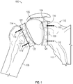
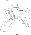
- FIG. 1 shows a stemless shoulder implant 100 in accordance with at least one example of the present application.
- Stemless shoulder implant 100 can include a humeral component 102, a glenoid component 104, and an articulation component 106.
- Humeral component 102 can be attached to a humerus 108 and glenoid component 104 can be attached to a glenoid cavity 110 of a scapula 112.
- the interface between humerus 108 and humeral component 102 and the interface between glenoid cavity 110 and glenoid component 104 can be resected bone.
- Bone cement 114, bone screws 116, and/or other fasteners can be used to attach humeral component 102 to humerus 108 and glenoid component 104 to glenoid cavity 110.
- humeral component 102 and glenoid component 104 can each include one or more through holes 202.
- the through holes 202 can allow for bone screws 116 to pass through humeral component 102 and glenoid component 104 and into humerus 108 and glenoid cavity 110, respectively.
- bone cement 114 can be placed at various locations or coat the distal sides of humeral component 102 and glenoid component 104. Bone cement 114 can be used with or without bone screws 116 to attach humeral component 102 to humerus 108 and glenoid component 104 to glenoid cavity 110.
- Humeral component 102 can include a humeral peg 118 and glenoid component 104 can include a glenoid peg 120 that extends from a distal side of each component. Humeral peg 118 and glenoid peg 120 can be received within a recess located within humerus 108 and glenoid cavity 110, respectively.
- the proximal side of humeral component 102 can include a humeral articulation layer 122 and the proximal side of glenoid component 104 can include a glenoid articulation layer 124.
- Articulation component 106 can be "free floating" and disposed between, but not attached to, humeral articulation layer 122 and glenoid articulation layer 124. As discussed herein, humeral component 102 and glenoid component 104 each can include a concave portion. Articulation component 106 can be ovoid or circular in shape and can rest between the concave portions of humeral component 102 and glenoid component 104. As will be discussed below, during articulation component 106 can be inserted via an incision in an axilla region of a patient or deltopectoris or deltoid splitting. After implantation, articulation component 106 can be held in place by a joint capsule of the shoulder.
- humeral articulation layer 122 can be a separate component from humeral component 102 and glenoid articulation layer 124 can be separate component from glenoid component 104.
- Glenoid peg 120 and humeral peg 118 can also be separate components. As such, a surgeon can select the appropriate components during a surgery.
- a surgeon may decide to use a concave glenoid component 104 without glenoid articulation layer 124 and a convex humeral component (such as a humeral component 402 described below) with a humeral articulation layer (such as a humeral articulation layer 422 described below).
- a convex humeral component such as a humeral component 402 described below
- a humeral articulation layer such as a humeral articulation layer 422 described below.
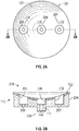
- FIGS. 2A-2C show a glenoid component or a humeral component having concave articular surfaces, in accordance with at least one example of the present application.
- FIGS. 2A-2C will be referenced with respect to humeral component 102.
- the discussion of FIGS. 2A-2C also applies to glenoid component 104 as well.
- Humeral component 102 can include a component body 204 that can include holes 202. Each of holes 202 can also include a recess 206. The recess 206 can allow a fastener, such as a bone screw 116, to be recessed into humeral component 102. Recess 206 can be filled with a plug or other filler (not shown) after humeral component 102 has been attached to humerus 108. Humeral component 102 can also include humeral peg 118, which can have a hole 202. Humeral peg 118 can also be fluted. Humeral component 102 can be formed of one or more materials. For example, humeral component 102 can be formed of a ceramic. In addition, humeral component 102 can be formed partially of a porous metal, such as tantalum, and partially of a non-porous metal such as stainless steel or cobalt chrome.
- Humeral component 102 can be formed of a highly porous, three-dimensional metallic structure.
- a highly porous, three-dimensional metallic structure can incorporate one or more of a variety of biocompatible metals such as but not limited to titanium, a titanium alloy, cobalt chromium, cobalt chromium molybdenum, tantalum, a tantalum alloy, niobium, or alloys of tantalum and niobium with one another or with other metals.
- Such structures are particularly suited for contacting bone and/or soft tissue, and in this regard, can be useful as bone substitutes and other implants and implant components that are receptive to cell and tissue ingrowth, for example, by allowing bony tissue or other tissue to grow into the porous structure over time to enhance fixation (e.g., osseointegration) between the structure and surrounding bodily structures.
- an open porous metal structure, or a portion thereof may have a bulk porosity as low as 55%, 65%, or 75% or as high as 80%, 85%, or 90%, or within any range defined between any pair of the foregoing values, and in this regard, such structures can provide lightweight, yet strong porous implants.
- porous metal structures are capable of withstanding extreme mechanical loads at the time of implantation and over long periods of time, for example, where a highly porous, three-dimensional metallic structure is forcefully impacted and press fit into a bone, by itself or connected to another implant, and maintains its shape during impaction and following many months or years of service in the body.
- Such structures can be manufactured according to any suitable technique or process.
- An example of an open porous metal structure is produced using Trabecular MetalTM Technology available from Zimmer, Inc., of Warsaw, Indiana. Trabecular MetalTM is a trademark of Zimmer, Inc.
- Such a material may be formed from a reticulated vitreous carbon foam substrate which is infiltrated and coated with a biocompatible metal, such as tantalum, by a chemical vapor deposition ("CVD") process in the manner disclosed in detail in U.S. Patent No. 5,282,861 and in Levine, B.R., et al., "Experimental and Clinical Performance of Porous Tantalum in Orthopedic Surgery", Biomaterials 27 (2006) 4671-4681 .
- CVD chemical vapor deposition
- a highly porous, three-dimensional metallic structure will be fabricated using a selective laser sintering (SLS) or other additive manufacturing-type process such as direct metal laser sintering or electron beam melting.
- SLS selective laser sintering
- a three-dimensional porous article is produced in layer-wise fashion from a laser-fusible powder, e.g., a single-component metal powder, which is deposited one layer at a time. The powder is fused, remelted or sintered, by the application of laser energy that is directed to portions of the powder layer corresponding to a cross section of the article.
- a laser selectively fuses powdered material by scanning cross-sections generated from a 3-D digital description of the article, e.g., from a CAD file or scan data, on the surface of a powder bed. Complex geometries can be created using such techniques, and in some instances, net shape and near net shape implants are constructed.
- a non-porous or essentially non-porous base substrate will provide a foundation upon which a three-dimensional porous structure will be built and fused thereto using a selective laser sintering (SLS) or other additive manufacturing-type process.
- SLS selective laser sintering
- Such substrates can incorporate one or more of a variety of biocompatible metals such as any of those disclosed herein.
- a highly porous, three-dimensional metallic structure will include a large plurality of ligaments that define open voids (e.g., pores) or channels between the ligaments.
- the open spaces between the ligaments form a matrix of continuous channels having few or no dead ends, such that growth of soft tissue and/or bone through the open porous metal is substantially uninhibited.
- exterior surfaces of an open porous metal structure can feature terminating ends of the above-described ligaments. Such terminating ends can be referred to as struts, and they can generate a high coefficient of friction along an exposed porous metal surface.
- Such features can impart an enhanced affixation ability to an exposed porous metal surface for adhering to bone and soft tissue.
- a small percentage of the substrate may be in direct contact with the ligaments of the highly porous structure, for example, approximately 15%, 20%, or 25%, of the surface area of the substrate may be in direct contact with the ligaments of the highly porous structure.
- a highly porous, three-dimensional metallic structure may be fabricated such that it comprises a variety of densities in order to selectively tailor the structure for particular orthopedic applications, for example, by matching the structure to surrounding natural tissue in order to provide an improved matrix for tissue ingrowth and mineralization.
- Such structures can be isotropic or anisotropic.
- an open porous metal structure may be fabricated to have a substantially uniform porosity, density, void (pore) size, pore shape, and/or pore orientation throughout, or to have one or more features such as porosity, density, void (pore) size, pore shape, and/or pore orientation being varied within the structure, or within a portion thereof.
- an open porous metal structure may have a different pore size, pore shape, and/or porosity at different regions, layers, and surfaces of the structure.
- the ability to selectively tailor the structural properties of the open porous metal enables, for example, tailoring of the structure for distributing stress loads throughout the surrounding tissue and promoting specific tissue ingrown within the open porous metal.
- a highly porous, three-dimensional metallic structure, once formed, will be infiltrated and coated with one or more coating materials such as biocompatible metals such as any of those disclosed herein.
- a distal side 208 can include humeral peg 118.
- distal side 208 can be shaped to engage a resected portion of humerus 108.
- Distal side 208 can be flat, concave, or convex.
- distal side 208 can have a custom profile. For example, using imaging techniques such as CT or MRI, humeral component 102 can be custom designed for a specific patient. As such, a physician can request that distal side 208 have a mixture of flat, concave, and convex portions to assist with mating humeral component 102 to humerus 108.
- Humeral component 102 can also include a proximal side 210.
- Proximal side 210 can be concave in shape.
- the profile of proximal side 210 can correspond to a profile of articulation component 106. Having corresponding mating surfaces can allow humeral component 102 to move freely along articulation component 106.
- Humeral articulation layer 122 can be attached to humeral component 102.
- Humeral articulation layer 122 can be formed on humeral component 102 via chemical vapor deposition.
- Humeral articulation layer 122 can be formed of a ceramic material.
- Humeral articulation layer 122 can also be formed of a polymer such as, but not limited to, a vitamin E stabilized polyethylene, sometimes referred to as a Vitamin E poly.
- a portion of humeral component 102 can also form humeral articulation layer 122.
- a portion of humeral component 102 can be a polished metal that mates with a convex portion of articulation component 106.
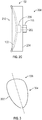
- FIG. 3 shows an articulation component 106 in accordance with at least one example of the present application.
- Articulation component 106 can be generally spherical in shape.
- articulation component 106 can be generally ovoid or circular in shape.
- Articulation component 106 can include an outer surface that includes a first portion 302 that can be convex in shape.
- First portion 302 can be configured to mate with concave portion of proximal side 210 of humeral component 102.
- the outer surface of articulation component 106 can also include a second portion 304 that can be convex in shape.
- Second portion 304 can be configured to mate with a concave portion of glenoid component 104.
- first portion 302 can be convex and second portion 304 can be concave to mate with corresponding concave and convex portions on humeral component 102 and glenoid component 104, respectively.
- first portion 302 can be concave and second portion 304 can be convex to mate with corresponding convex and concave portions on humeral component 102 and glenoid component 104, respectively.
- Articulation component 106 can be formed of a polymer such as a vitamin E stabilized polyethylene. Articulation component 106 can be formed of a ceramic or metal, such as cobalt chrome. In an example, articulation component 106 can be formed of combinations of a polymer, ceramic, or metal. In an example, articulation component 106 can be formed from a balloon.
- Articulation component 106 also can be formed using an inflatable membrane.
- articulation component 106 can be formed of a pliable material such as, but not limited to, a vitamin E stabilized polyethylene or a biocompatible polymer.
- the pliable material can define a cavity into which a fluid or other flowable substance can be injected. Upon injection of the fluid, the cavity defined by the flowable material can inflate to fill a void defined by the glenoid component 104 and the humeral component 102.
- the glenoid component 104 and the humeral component 102 can define a void to receive the articulation component 106. Filling of the articulation component 106 after it is received within the void defined by the glenoid component 104 and the humeral component 102 can allow the articulation component to be custom sized by a surgeon during a surgical procedure. In addition, by inflating the pliable material within the void, trauma to the shoulder muscles, tendons, and ligaments can be minimized.
- the articulation component 106 can have a reduced size when inserted into the void defined by the glenoid component 104 and the humeral component 102, stretching or otherwise disturbing muscles, tendons, and ligaments proximate the surgical site can be minimized as compared to inserting a fully formed articulation component 106. Furthermore, during a revision, the pliable material can be removed without damage to the glenoid component 104, the humeral component 102, or surrounding tissue.
- FIG. 4 shows another stemless shoulder implant 400 in accordance with at least one example of the present application.
- Stemless shoulder implant 400 can include a humeral component 402, a glenoid component 404, and an articulation component 406.
- Humeral component 402 can be attached to a humerus 408 and glenoid component 404 can be attached to a glenoid cavity 410 of a scapula 412.
- the interface between humerus 408 and humeral component 402 and the interface between glenoid cavity 410 and glenoid component 404 can be resected bone.
- Bone cement 414, bone screws 416, or other fasteners can be used to attach humeral component 402 to humerus 408 and glenoid component 404 to glenoid cavity 410.
- humeral component 402 and glenoid component 404 can each include one or more through holes 502.
- the through holes 502 can allow for fasteners, such as bone screws 416, to pass through humeral component 402 and glenoid component 404 and into humerus 408 and glenoid cavity 410, respectively.
- bone cement 414 can be placed at various location or coat the distal sides of humeral component 402 and glenoid component 404. Bone cement 414 can be used with or without bone screws 416 to attach humeral component 402 to humerus 408 and glenoid component 404 to glenoid cavity 410.
- Humeral component 402 can include a humeral peg 418 and glenoid component 404 can include a glenoid peg 420 that extends from a distal side of each component. Humeral peg 418 and glenoid peg 420 can be received within a recess located within humerus 408 and glenoid cavity 410, respectively.
- the proximal side of humeral component 402 can include a humeral articulation layer 422 and the proximal side of glenoid component 404 can include a glenoid articulation layer 424.
- Articulation component 406 can be "free floating" and disposed between, but not attached to, humeral articulation layer 422 and glenoid articulation layer 424.
- humeral component 402 and glenoid component 404 each can include a convex portion.
- Articulation component 406 can be ovoid or circular in shape and have corresponding concave portions. Articulation component 406 can rest between the convex portions of humeral component 402 and glenoid component 404.
- articulation component 406 can be inserted via an incision in an axilla region of a patient. After implantation, articulation component 406 can be held in place by a joint capsule of the shoulder.
- articulation component 406 can be made of a pliable material and inflated within a cavity defined by the humeral component 402 and the glenoid component 404.
- humeral articulation layer 422 can be a separate component from humeral component 402 and glenoid articulation layer 424 can be separate component from glenoid component 404.
- Glenoid peg 420 and humeral peg 418 can also be separate components.
- a surgeon can select the appropriate components during a surgery. For instance, during surgery a surgeon may decide to use a convex glenoid component 404 with glenoid articulation layer 424 and a concave humeral component (such as humeral component 102 described above) without a humeral articulation layer.
- FIGS. 5A-5C show a glenoid component or a humeral component having convex articular surfaces, in accordance with at least one example of the present application.
- FIGS. 5A-5C will be referenced with respect to glenoid component 404.
- the discussion of FIGS. 5A-5C also applies to humeral component 402 as well.
- Glenoid component 404 can include a component body 504 that can include holes 502. Each of holes 502 can also include a recess 506. The recess 506 can allow screws 416 to be recessed into glenoid component 404. Recess 506 can be filled with a plug or other filler (not shown) after glenoid component 404 has been attached to glenoid cavity 410. Glenoid component 404 can also include glenoid peg 420, which can have a hole 502. Glenoid peg 420 can also be fluted. Glenoid component 404 can be formed of one or more materials.
- glenoid component 404 can be formed partially of a porous metal, such as tantalum, and partially of a non-porous metal such as stainless steel. Glenoid component 404 can also be formed of a ceramic. Glenoid component 404 can be formed of a highly porous, three-dimensional metallic structure as described with respect to humeral component 102.
- a distal side 508 (sometimes referred to as a medial side) can include glenoid peg 420.
- distal side 508 can be shaped to engage a resected portion of glenoid cavity 410.
- Distal side 508 can be flat, concave, or convex.
- distal side 508 can have a custom profile. For example, using imaging techniques such as CT or MRI, glenoid component 404 can be custom designed for a specific patient. As such, a physician can request that distal side 508 have a mixture of flat, concave, and convex portions to assist with mating glenoid component 404 to glenoid cavity 410.
- Glenoid component 404 can also include a proximal side 510 (sometimes referred to as a lateral side).
- Proximal side 510 can be convex in shape.
- the profile of proximal side 510 can correspond to a profile of articulation component 406. Having corresponding mating surfaces can allow glenoid component 404 to move freely along articulation component 406.
- Glenoid articulation layer 424 can be attached to glenoid component 404. Glenoid articulation layer 424 can be formed on glenoid component 404 via chemical vapor deposition. Glenoid articulation layer 424 can be formed of a ceramic material. Glenoid articulation layer 424 can also be formed of a polymer such as, but not limited to, a vitamin E stabilized polyethylene. A portion of glenoid component 404 can also form glenoid articulation layer 424. For example, a portion of glenoid component 404 can be a polished metal that mates with a concave portion of articulation component 406.
- FIG. 6 shows another articulation component 406 in accordance with at least one example of the present application.
- Articulation component 406 can include an outer surface that includes a first portion 602 that can be concave in shape.
- First portion 602 can be configured to mate with a convex portion of humeral component 402.
- the outer surface of articulation component 406 can also include a second portion 604 that can be convex in shape.
- Second portion 604 can be configured to mate with convex portion of proximal side 510 of glenoid component 404.
- first portion 602 can be convex and second portion 604 can be concave to mate with corresponding concave and convex portions on humeral component 402 and glenoid component 404, respectively.
- first portion 602 can be concave and second portion 604 can be convex to mate with corresponding convex and concave portions on humeral component 402 and glenoid component 404, respectively.
- Articulation component 406 can be formed of a polymer such as a vitamin E stabilized polyethylene. Articulation component 406 can be formed of a ceramic or metal, such as cobalt chrome. In an example, articulation component 406 can be formed of combinations of a polymer, ceramic, or metal. In an example, articulation component 406 can be formed from a balloon.
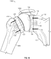
- FIG. 9 shows another stemless shoulder implant 900 in accordance with at least one example of the present application.
- Stemless shoulder implant 900 can include a humeral component 102, a glenoid component 404, and an articulation component 902.
- Humeral component 102 can be attached to a humerus 108 and glenoid component 404 can be attached to a glenoid cavity 410 of a scapula 412.
- the interface between humerus 108 and humeral component 102 and the interface between glenoid cavity 410 and glenoid component 404 can be resected bone.
- Bone cement 414, bone screws 416 and 116, or other fasteners can be used to attach humeral component 102 to humerus 108 and glenoid component 404 to glenoid cavity 410.
- humeral component 102 and glenoid component 404 can each include one or more through holes 202 and 502.
- the through holes 202 and 502 can allow for fasteners, such as bone screws 116 and 416, to pass through humeral component 102 and glenoid component 404 and into humerus 108 and glenoid cavity 410, respectively.
- bone cement 114 and 414 can be placed at various location or coat the distal sides of humeral component 102 and glenoid component 404. Bone cement 114 and 414 can be used with or without bone screws 116 and 416 to attach humeral component 102 to humerus 108 and glenoid component 404 to glenoid cavity 410.
- Humeral component 102 can include a humeral peg 118 and glenoid component 404 can include a glenoid peg 420 that extends from a distal side of each component. Humeral peg 118 and glenoid peg 420 can be received within a recess located within humerus 108 and glenoid cavity 410, respectively.
- the proximal side of humeral component 102 can include a humeral articulation layer 122 and the proximal side of glenoid component 404 can include a glenoid articulation layer 424.
- Articulation component 902 can be "free floating" and disposed between, but not attached to, humeral articulation layer 122 and glenoid articulation layer 424. As discussed herein, humeral component 102 and glenoid component 404 each can include a concave and convex portions. Articulation component 902 can be ovoid or circular in shape and have corresponding convex and concave portions. Articulation component 902 can rest between the concave and convex portions of humeral component 102 and glenoid component 404. As will be discussed below, during implantation articulation component 902 can be inserted via an incision in an axilla region of a patient.
- articulation component 902 can be held in place by a joint capsule of the shoulder.
- articulation component 902 can be made of a pliable material and inflated within a cavity defined by the humeral component 102 and the glenoid component 404.
- humeral articulation layer 122 can be a separate component from humeral component 102 and glenoid articulation layer 424 can be separate component from glenoid component 404.
- Glenoid peg 420 and humeral peg 118 can also be separate components.
- a surgeon can select the appropriate components during a surgery. For instance, during surgery a surgeon may decide to use a convex glenoid component 404 with glenoid articulation layer 424 and a concave humeral component 102 without a humeral articulation layer.
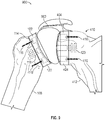
- FIG. 10 shows another stemless shoulder implant 1000 in accordance with at least one example of the present application.
- Stemless shoulder implant 1000 can include a humeral component 402, a glenoid component 104, and an articulation component 1002.
- Humeral component 402 can be attached to a humerus 408 and glenoid component 104 can be attached to a glenoid cavity 110 of a scapula 112.
- the interface between humerus 408 and humeral component 402 and the interface between glenoid cavity 110 and glenoid component 104 can be resected bone.
- Bone cement 114 and 414, bone screws 116 and 416, or other fasteners can be used to attach humeral component 402 to humerus 408 and glenoid component 104 to glenoid cavity 110.
- humeral component 402 and glenoid component 404 can each include one or more through holes 202 and 502.
- the through holes 202 and 502 can allow for fasteners, such as bone screws 116 and 416, to pass through humeral component 402 and glenoid component 104 and into humerus 408 and glenoid cavity 110, respectively.
- bone cement 114 and 414 can be placed at various location or coat the distal sides of humeral component 402 and glenoid component 104. Bone cement 114 and 414 can be used with or without bone screws 116 and 416 to attach humeral component 402 to humerus 408 and glenoid component 104 to glenoid cavity 110.
- Humeral component 402 can include a humeral peg 418 and glenoid component 104 can include a glenoid peg 120 that extends from a distal side of each component. Humeral peg 418 and glenoid peg 120 can be received within a recess located within humerus 408 and glenoid cavity 110, respectively.
- the proximal side of humeral component 402 can include a humeral articulation layer 422 and the proximal side of glenoid component 104 can include a glenoid articulation layer 124.
- Articulation component 1002 can be "free floating" and disposed between, but not attached to, humeral articulation layer 422 and glenoid articulation layer 124. As discussed herein, humeral component 402 and glenoid component 104 each can include a convex portion. Articulation component 1002 can be ovoid or circular in shape and have corresponding convex and concave portions. Articulation component 1002 can rest between the convex and concave portions of humeral component 402 and glenoid component 104. As will be discussed below, during implantation articulation component 1002 can be inserted via an incision in an axilla region of a patient.
- articulation component 1002 can be held in place by a joint capsule of the shoulder.
- articulation component 1002 can be made of a pliable material and inflated within a cavity defined by the humeral component 402 and the glenoid component 104.
- humeral articulation layer 422 can be a separate component from humeral component 402 and glenoid articulation layer 124 can be separate component from glenoid component 104.
- Glenoid peg 420 and humeral peg 118 can also be separate components.
- a surgeon can select the appropriate components during a surgery. For instance, during surgery a surgeon may decide to use a concave glenoid component 404 with glenoid articulation layer 424 and a convex humeral component 102 without a humeral articulation layer.
- FIGS. 7A and 7B show a deltopectoral surgical technique in accordance with at least one example of the present application.
- a patient can lie on his or her back with his or her chest 702 facing up.
- a surgeon can make an incision along an incision line 704.
- Incision line 704 can extend from proximal a clavicle 706 and extend across the acromion 708 and past a humerus 710.
- a deltoid muscle 712 and a pectoralis major muscle 714 can be retracted using a first retractor 716 and a second retractor 718, respectively.
- a humeral head 724 and glenoid 726 can be resected.
- a humeral component such as humeral component 102 or 402
- a glenoid component such as glenoid component 104 or 404
- a glenoid component can be attached to the resected glenoid cavity.
- the glenoid component and the humeral component can be attached to the glenoid cavity and humerus, respectively, using bone cement, bone fasteners, or a combination thereof.
- the glenoid component and the humeral component can each have a peg, such as peg 118, 120, 418, or 420, that can be inserted into a recess cut or drilled into the glenoid cavity or the humerus.
- the peg can be fluted.
- an articulation component such as articulation component 106 or 406 can be inserted between the glenoid component and the humeral component.
- the articulation component can free float between the glenoid component and the humeral component.
- the articulation component can be implanted such that it is not attached to either the glenoid component or the humeral component.
- a rotator cuff, deltoid muscle 712, pectoralis major muscle 714, as well as other tendons and ligaments that make up the joint capsule can hold the articulation component in place between the glenoid component and the humeral component.
- subscapularis tendon 720 and anterior joint capsule 722 can be repaired with sutures.
- Deltoid muscle 712 and pectoralis major muscle 714 can be released by removing first retractor 716 and second retractor 718 and the incision closed with sutures or staples.
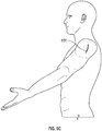
- FIGS. 8A and 8B show an axillary recess surgical technique in accordance with at least one example of the present application.
- the shoulder joint 800 can include an axillary recess 802, a humerus 804, a scapula 806 having a glenoid cavity 808, a corocoid process 810, an acromion 812, a glenohumeral ligament 814, a supraspinatus tendon 816, a subdeltoid bursa 818, and a deltoid muscle 820.
- FIG. 8A the shoulder joint 800 can include an axillary recess 802, a humerus 804, a scapula 806 having a glenoid cavity 808, a corocoid process 810, an acromion 812, a glenohumeral ligament 814, a supraspinatus tendon 816, a subdeltoid bursa 8
- shoulder joint 800 can also include an anterior band 822, an inferior glenohumeral ligament 824, middle glenohumeral ligament 826, subscapularis tendon 828, superior glenohumeral ligament 830, a biceps brachit tendon 832, a coracoacromial ligament 834, an infraspinatus tendon 836, glenoid cavity cartilage 838, a teres minor tendon 840, and a posterior band 842.
- a surgeon can make an incision in an axilla region, such as in axillary recess 802. Once the axilla region has been incised, a portion of humerus 804 and glenoid cavity 808 can be resected through the incision. Additional material, such as for example, glenoid cavity cartilage 838, can be removed from shoulder joint 800 as needed via the incision.
- a humeral component such as humeral component 102 or 402 can be inserted through the incision.
- the humeral component can include a bone contacting surface and an opposing articular surface.
- the humeral component can be attached, via the bone contacting surface of the humeral component to the resected portion of humerus 804.
- the bone contacting surface of the humeral component can be shaped to mate with the resected portion of humerus 804.
- the bone contacting surfaces of the humeral component can be at least partially formed from a porous metal.
- the porous metal can facilitate bone ingrowth after implantation of the humeral component. The bone ingrowth can help solidify attachment of the humeral component to the resected portion of humerus 804.
- the humeral component can be attached to the resected portion of humerus 804 by applying bone cement to the bone contacting surface of the humeral component, the resected portion of humerus 804, or both.
- the humeral component can be attached to the resected portion of humerus 804 by inserting a bone fastener, such as screws 116 or 416, through the humeral component and into humerus 804.
- a glenoid component such as glenoid component 104 or 404, can be inserted through the incision.
- the glenoid component can include a bone contacting surface and an opposing articular surface.
- the glenoid component can be attached, via the bone contacting surface of the glenoid component to the resected portion of glenoid cavity 808.
- the bone contacting surface of the glenoid component can be shaped to mate with the resected portion of glenoid cavity 808.
- the glenoid component can be attached to the resected portion of glenoid cavity 808 by applying bone cement to the bone contacting surface of the glenoid component, the resected portion of glenoid cavity 808, or both.
- the glenoid component can be attached to the resected portion of glenoid cavity 808 by inserting a bone fastener, such as screws 116 or 416, through the glenoid component and into glenoid cavity 808.
- the bone contacting surfaces of the glenoid component can be at least partially formed from a porous metal.
- the porous metal can facilitate bone ingrowth after implantation of the glenoid component.
- the bone ingrowth can help solidity attachment of the glenoid component to the resected portion of glenoid cavity 808.
- an articulation component such as articulation component 106 or 406, can be inserted through the incision and between articular surfaces of the humeral component and the glenoid component.
- the articulation component can be held in between the humeral component and the glenoid component by at least deltoid muscle 820 and a rotator cuff, which can include teres minor tendon 840, infraspinatus tendon 836, and subdeltoid bursa 816.
- the surgical technique shown and described with regards to FIGS. 8A and 8B can have advantages over other surgical techniques.
- the surgical technique shown and described with regards to FIGS. 8A and 8B may not require disturbance of major muscle groups such as, but not limited to, the deltoid muscle, the pectoralis major muscles, and the rotator cuff muscles.
- the surgical technique shown and described with regards to FIGS. 8A and 8B may not require incisions in tendons or other ligaments such as, but not limited to, inferior glenohumeral ligament, middle glenohumeral ligament, subscapularis tendon, superior glenohumeral ligament, or biceps brachit tendon. Not disturbing major muscle groups or incising ligaments and tendons can lead to decreased recovery times because the major muscle groups, ligaments, and tendons may suffer less trauma or damage during surgery.
- the glenoid cavity 808 and humerus 804 can be accessed via an incision 850.
- an incision 850 the pectoralis, anterior deltoid, and middle deltoid muscles can be retracted to access glenoid cavity 808 and humerus 804 via deltoid splitting.
- the humerus and glenoid cavity can be prepared using reamers and/or saws.
- a sport's medicine arthroscopic cutter can be used to shape the humerus and the glenoid cavity.
- fillers such as balloons
- fillers can be used to fill gaps created during preparations.
Description
- The present disclosure relates to surgical implant systems, including implants, for performing a total shoulder arthroplasty, a hemi shoulder arthroplasty, or a reverse total shoulder arthroplasty. The closest prior art is document
US 2009/0287309 A1 , which defines the preamble ofclaim 1. - In a healthy shoulder, the proximal humerus is generally ball-shaped, and articulates within a socket, called the glenoid, formed by the scapula to form the shoulder joint. Conventional implant systems for the total replacement of the shoulder joint due to disease or trauma, i.e., a total shoulder arthroplasty, generally replicate the natural anatomy of the shoulder, and typically include a humeral component having a stem which fits within the humeral canal, and an articulating head which articulates within the socket of a glenoid component implanted within the glenoid of the scapula. An implant system for the replacement of only the humeral component of the shoulder joint, i.e., a hemi shoulder arthroplasty, typically includes only a humeral component which articulates within the natural glenoid socket of the scapula.
- In addition, "reverse" type implant systems have been developed in which the conventional ball-and-socket configuration that replicates the natural anatomy of the shoulder is reversed, such that a concave recessed articulating component is provided at the proximal end of the humeral component that articulates against a convex portion of the glenoid component. Such reverse shoulder implant systems are thought to provide an increased range of motion for treatment of glenohumeral arthritis associated with irreparable rotator cuff damage, for example, by moving the center of rotation between the humeral component and the glenoid component to allow the deltoid muscles to exert a greater lever arm on the humerus.
- The invention is defined in
claim 1 and preferred embodiments are defined in the dependant claims. - The above-mentioned and other features and advantages of this disclosure, and the manner of attaining them, will become more apparent and the disclosure itself will be better understood by reference to the following description of embodiments taken in conjunction with the accompanying drawings, wherein:
-
FIG. 1 shows an example of a stemless shoulder implant implanted within a shoulder; -
FIG. 2A shows a front view of an example humeral component having a concave articular surface; -
FIG. 2B shows a cross-sectional view of an example humeral component having a concave articular surface; -
FIG. 2C shows a side view of an example humeral component having a concave articular surface; -
FIG. 3 shows an example articulation component having convex portions; -
FIG. 4 shows an example of a stemless shoulder implant implanted within a shoulder; -
FIG. 5A shows a front view of an example glenoid component having a convex articular surface; -
FIG. 5B shows a cross-sectional view of an example glenoid component having a convex articular surface; -
FIG. 5C shows a side view of an example glenoid component having a convex articular surface; -
FIG. 6 shows an example articulation component having concave portions; -
FIG. 7A shows a schematic of a shoulder surgery site using a deltopectoral surgical technique; -
FIG. 7B shows a cross-section of a shoulder joint during a deltopectoral surgical technique; -
FIG. 8A shows a schematic of a shoulder surgery site using an axilla region surgical technique; -
FIG. 8B shows a cross-section of a shoulder joint during an axilla region surgical technique; -
FIG. 8C shows a schematic of a shoulder surgery site using a deltoid splitting technique; -
FIG. 9 shows an example of a stemless shoulder implant implanted within a shoulder; and -
FIG. 10 shows an example of a stemless shoulder implant implanted within a shoulder. - Corresponding reference characters indicate corresponding parts throughout the several views. The exemplifications set out herein illustrate example embodiments, and such examples are not to be construed as limiting the scope of the disclosure in any manner.
- As used herein, the following directional definitions apply. Anterior and posterior mean nearer the front or nearer the rear of the body, respectively; proximal and distal mean nearer to or further from the root of a structure, respectively; and medial and lateral mean nearer the sagittal plane or further from the sagittal plane, respectively. The sagittal plane is an imaginary vertical plane through the middle of the body that divides the body into right and left halves.
- Referring now to the figures,
FIG. 1 shows astemless shoulder implant 100 in accordance with at least one example of the present application.Stemless shoulder implant 100 can include ahumeral component 102, aglenoid component 104, and anarticulation component 106.Humeral component 102 can be attached to ahumerus 108 andglenoid component 104 can be attached to aglenoid cavity 110 of ascapula 112. The interface betweenhumerus 108 andhumeral component 102 and the interface betweenglenoid cavity 110 andglenoid component 104 can be resected bone. -
Bone cement 114,bone screws 116, and/or other fasteners can be used to attachhumeral component 102 tohumerus 108 andglenoid component 104 toglenoid cavity 110. For example, and as shown inFIGS. 2A-2C ,humeral component 102 andglenoid component 104 can each include one or more throughholes 202. The throughholes 202 can allow forbone screws 116 to pass throughhumeral component 102 andglenoid component 104 and intohumerus 108 andglenoid cavity 110, respectively. Furthermore,bone cement 114 can be placed at various locations or coat the distal sides ofhumeral component 102 andglenoid component 104.Bone cement 114 can be used with or withoutbone screws 116 to attachhumeral component 102 tohumerus 108 andglenoid component 104 toglenoid cavity 110. -
Humeral component 102 can include ahumeral peg 118 andglenoid component 104 can include aglenoid peg 120 that extends from a distal side of each component.Humeral peg 118 andglenoid peg 120 can be received within a recess located withinhumerus 108 andglenoid cavity 110, respectively. The proximal side ofhumeral component 102 can include ahumeral articulation layer 122 and the proximal side ofglenoid component 104 can include aglenoid articulation layer 124. -
Articulation component 106 can be "free floating" and disposed between, but not attached to,humeral articulation layer 122 andglenoid articulation layer 124. As discussed herein,humeral component 102 andglenoid component 104 each can include a concave portion.Articulation component 106 can be ovoid or circular in shape and can rest between the concave portions ofhumeral component 102 andglenoid component 104. As will be discussed below, duringimplantation articulation component 106 can be inserted via an incision in an axilla region of a patient or deltopectoris or deltoid splitting. After implantation,articulation component 106 can be held in place by a joint capsule of the shoulder. - The various components can be modular and part of a kit of components. For example, as discussed herein,
humeral articulation layer 122 can be a separate component fromhumeral component 102 andglenoid articulation layer 124 can be separate component fromglenoid component 104.Glenoid peg 120 andhumeral peg 118 can also be separate components. As such, a surgeon can select the appropriate components during a surgery. For instance, during surgery a surgeon may decide to use a concaveglenoid component 104 withoutglenoid articulation layer 124 and a convex humeral component (such as ahumeral component 402 described below) with a humeral articulation layer (such as ahumeral articulation layer 422 described below). -
FIGS. 2A-2C show a glenoid component or a humeral component having concave articular surfaces, in accordance with at least one example of the present application. For simplicity,FIGS. 2A-2C will be referenced with respect tohumeral component 102. However, the discussion ofFIGS. 2A-2C also applies toglenoid component 104 as well. -
Humeral component 102 can include acomponent body 204 that can includeholes 202. Each ofholes 202 can also include arecess 206. Therecess 206 can allow a fastener, such as abone screw 116, to be recessed intohumeral component 102. Recess 206 can be filled with a plug or other filler (not shown) afterhumeral component 102 has been attached tohumerus 108.Humeral component 102 can also includehumeral peg 118, which can have ahole 202.Humeral peg 118 can also be fluted.Humeral component 102 can be formed of one or more materials. For example,humeral component 102 can be formed of a ceramic. In addition,humeral component 102 can be formed partially of a porous metal, such as tantalum, and partially of a non-porous metal such as stainless steel or cobalt chrome. -
Humeral component 102 can be formed of a highly porous, three-dimensional metallic structure. A highly porous, three-dimensional metallic structure can incorporate one or more of a variety of biocompatible metals such as but not limited to titanium, a titanium alloy, cobalt chromium, cobalt chromium molybdenum, tantalum, a tantalum alloy, niobium, or alloys of tantalum and niobium with one another or with other metals. Such structures are particularly suited for contacting bone and/or soft tissue, and in this regard, can be useful as bone substitutes and other implants and implant components that are receptive to cell and tissue ingrowth, for example, by allowing bony tissue or other tissue to grow into the porous structure over time to enhance fixation (e.g., osseointegration) between the structure and surrounding bodily structures. According to certain embodiments of the present disclosure, an open porous metal structure, or a portion thereof may have a bulk porosity as low as 55%, 65%, or 75% or as high as 80%, 85%, or 90%, or within any range defined between any pair of the foregoing values, and in this regard, such structures can provide lightweight, yet strong porous implants. Certain porous metal structures, despite having such high porosities, are capable of withstanding extreme mechanical loads at the time of implantation and over long periods of time, for example, where a highly porous, three-dimensional metallic structure is forcefully impacted and press fit into a bone, by itself or connected to another implant, and maintains its shape during impaction and following many months or years of service in the body. Such structures can be manufactured according to any suitable technique or process. An example of an open porous metal structure is produced using Trabecular Metal™ Technology available from Zimmer, Inc., of Warsaw, Indiana. Trabecular Metal™ is a trademark of Zimmer, Inc. Such a material may be formed from a reticulated vitreous carbon foam substrate which is infiltrated and coated with a biocompatible metal, such as tantalum, by a chemical vapor deposition ("CVD") process in the manner disclosed in detail inU.S. Patent No. 5,282,861 and in Levine, B.R., et al., "Experimental and Clinical Performance of Porous Tantalum in Orthopedic Surgery", Biomaterials 27 (2006) 4671-4681. - In some instances, a highly porous, three-dimensional metallic structure will be fabricated using a selective laser sintering (SLS) or other additive manufacturing-type process such as direct metal laser sintering or electron beam melting. In one example, a three-dimensional porous article is produced in layer-wise fashion from a laser-fusible powder, e.g., a single-component metal powder, which is deposited one layer at a time. The powder is fused, remelted or sintered, by the application of laser energy that is directed to portions of the powder layer corresponding to a cross section of the article. After the fusing of the powder in each layer, an additional layer of powder is deposited, and a further fusing step is carried out, with fused portions or lateral layers fusing so as to fuse portions of previous laid layers until a three-dimensional article is complete. In certain embodiments, a laser selectively fuses powdered material by scanning cross-sections generated from a 3-D digital description of the article, e.g., from a CAD file or scan data, on the surface of a powder bed. Complex geometries can be created using such techniques, and in some instances, net shape and near net shape implants are constructed. In some embodiments, a non-porous or essentially non-porous base substrate will provide a foundation upon which a three-dimensional porous structure will be built and fused thereto using a selective laser sintering (SLS) or other additive manufacturing-type process. Such substrates can incorporate one or more of a variety of biocompatible metals such as any of those disclosed herein.
- Generally, a highly porous, three-dimensional metallic structure will include a large plurality of ligaments that define open voids (e.g., pores) or channels between the ligaments. The open spaces between the ligaments form a matrix of continuous channels having few or no dead ends, such that growth of soft tissue and/or bone through the open porous metal is substantially uninhibited. According to some aspects of the present disclosure, exterior surfaces of an open porous metal structure can feature terminating ends of the above-described ligaments. Such terminating ends can be referred to as struts, and they can generate a high coefficient of friction along an exposed porous metal surface. Such features can impart an enhanced affixation ability to an exposed porous metal surface for adhering to bone and soft tissue. Also, when such highly porous metal structures are coupled to an underlying substrate, a small percentage of the substrate may be in direct contact with the ligaments of the highly porous structure, for example, approximately 15%, 20%, or 25%, of the surface area of the substrate may be in direct contact with the ligaments of the highly porous structure.
- A highly porous, three-dimensional metallic structure may be fabricated such that it comprises a variety of densities in order to selectively tailor the structure for particular orthopedic applications, for example, by matching the structure to surrounding natural tissue in order to provide an improved matrix for tissue ingrowth and mineralization. Such structures can be isotropic or anisotropic. In this regard, according to certain embodiments, an open porous metal structure may be fabricated to have a substantially uniform porosity, density, void (pore) size, pore shape, and/or pore orientation throughout, or to have one or more features such as porosity, density, void (pore) size, pore shape, and/or pore orientation being varied within the structure, or within a portion thereof. For example, an open porous metal structure may have a different pore size, pore shape, and/or porosity at different regions, layers, and surfaces of the structure. The ability to selectively tailor the structural properties of the open porous metal enables, for example, tailoring of the structure for distributing stress loads throughout the surrounding tissue and promoting specific tissue ingrown within the open porous metal. In some instances, a highly porous, three-dimensional metallic structure, once formed, will be infiltrated and coated with one or more coating materials such as biocompatible metals such as any of those disclosed herein.
- A
distal side 208 can includehumeral peg 118. In addition,distal side 208 can be shaped to engage a resected portion ofhumerus 108.Distal side 208 can be flat, concave, or convex. In addition,distal side 208 can have a custom profile. For example, using imaging techniques such as CT or MRI,humeral component 102 can be custom designed for a specific patient. As such, a physician can request thatdistal side 208 have a mixture of flat, concave, and convex portions to assist with matinghumeral component 102 tohumerus 108. -
Humeral component 102 can also include aproximal side 210.Proximal side 210 can be concave in shape. The profile ofproximal side 210 can correspond to a profile ofarticulation component 106. Having corresponding mating surfaces can allowhumeral component 102 to move freely alongarticulation component 106. -
Humeral articulation layer 122 can be attached tohumeral component 102.Humeral articulation layer 122 can be formed onhumeral component 102 via chemical vapor deposition.Humeral articulation layer 122 can be formed of a ceramic material.Humeral articulation layer 122 can also be formed of a polymer such as, but not limited to, a vitamin E stabilized polyethylene, sometimes referred to as a Vitamin E poly. A portion ofhumeral component 102 can also formhumeral articulation layer 122. For example, a portion ofhumeral component 102 can be a polished metal that mates with a convex portion ofarticulation component 106. -
FIG. 3 shows anarticulation component 106 in accordance with at least one example of the present application.Articulation component 106 can be generally spherical in shape. In addition,articulation component 106 can be generally ovoid or circular in shape. -
Articulation component 106 can include an outer surface that includes afirst portion 302 that can be convex in shape.First portion 302 can be configured to mate with concave portion ofproximal side 210 ofhumeral component 102. The outer surface ofarticulation component 106 can also include asecond portion 304 that can be convex in shape.Second portion 304 can be configured to mate with a concave portion ofglenoid component 104. In an example,first portion 302 can be convex andsecond portion 304 can be concave to mate with corresponding concave and convex portions onhumeral component 102 andglenoid component 104, respectively. In another example,first portion 302 can be concave andsecond portion 304 can be convex to mate with corresponding convex and concave portions onhumeral component 102 andglenoid component 104, respectively. -
Articulation component 106 can be formed of a polymer such as a vitamin E stabilized polyethylene.Articulation component 106 can be formed of a ceramic or metal, such as cobalt chrome. In an example,articulation component 106 can be formed of combinations of a polymer, ceramic, or metal. In an example,articulation component 106 can be formed from a balloon. -
Articulation component 106 also can be formed using an inflatable membrane. For example,articulation component 106 can be formed of a pliable material such as, but not limited to, a vitamin E stabilized polyethylene or a biocompatible polymer. The pliable material can define a cavity into which a fluid or other flowable substance can be injected. Upon injection of the fluid, the cavity defined by the flowable material can inflate to fill a void defined by theglenoid component 104 and thehumeral component 102. - As disclosed herein, the
glenoid component 104 and thehumeral component 102 can define a void to receive thearticulation component 106. Filling of thearticulation component 106 after it is received within the void defined by theglenoid component 104 and thehumeral component 102 can allow the articulation component to be custom sized by a surgeon during a surgical procedure. In addition, by inflating the pliable material within the void, trauma to the shoulder muscles, tendons, and ligaments can be minimized. For instance, because thearticulation component 106 can have a reduced size when inserted into the void defined by theglenoid component 104 and thehumeral component 102, stretching or otherwise disturbing muscles, tendons, and ligaments proximate the surgical site can be minimized as compared to inserting a fully formedarticulation component 106. Furthermore, during a revision, the pliable material can be removed without damage to theglenoid component 104, thehumeral component 102, or surrounding tissue. -
FIG. 4 shows anotherstemless shoulder implant 400 in accordance with at least one example of the present application.Stemless shoulder implant 400 can include ahumeral component 402, aglenoid component 404, and anarticulation component 406.Humeral component 402 can be attached to ahumerus 408 andglenoid component 404 can be attached to aglenoid cavity 410 of ascapula 412. The interface betweenhumerus 408 andhumeral component 402 and the interface betweenglenoid cavity 410 andglenoid component 404 can be resected bone. -
Bone cement 414, bone screws 416, or other fasteners can be used to attachhumeral component 402 tohumerus 408 andglenoid component 404 toglenoid cavity 410. For example, and as shown inFIGS. 5A-5C humeral component 402 andglenoid component 404 can each include one or more throughholes 502. The throughholes 502 can allow for fasteners, such as bone screws 416, to pass throughhumeral component 402 andglenoid component 404 and intohumerus 408 andglenoid cavity 410, respectively. Furthermore,bone cement 414 can be placed at various location or coat the distal sides ofhumeral component 402 andglenoid component 404.Bone cement 414 can be used with or without bone screws 416 to attachhumeral component 402 tohumerus 408 andglenoid component 404 toglenoid cavity 410. -
Humeral component 402 can include ahumeral peg 418 andglenoid component 404 can include aglenoid peg 420 that extends from a distal side of each component.Humeral peg 418 andglenoid peg 420 can be received within a recess located withinhumerus 408 andglenoid cavity 410, respectively. The proximal side ofhumeral component 402 can include ahumeral articulation layer 422 and the proximal side ofglenoid component 404 can include aglenoid articulation layer 424. -
Articulation component 406 can be "free floating" and disposed between, but not attached to,humeral articulation layer 422 andglenoid articulation layer 424. As discussed herein,humeral component 402 andglenoid component 404 each can include a convex portion.Articulation component 406 can be ovoid or circular in shape and have corresponding concave portions.Articulation component 406 can rest between the convex portions ofhumeral component 402 andglenoid component 404. As will be discussed below, duringimplantation articulation component 406 can be inserted via an incision in an axilla region of a patient. After implantation,articulation component 406 can be held in place by a joint capsule of the shoulder. In addition, as described above regardingarticulation component 106,articulation component 406 can be made of a pliable material and inflated within a cavity defined by thehumeral component 402 and theglenoid component 404. - As described herein, the various components can be modular and part of a kit of components. For example, as discussed herein,
humeral articulation layer 422 can be a separate component fromhumeral component 402 andglenoid articulation layer 424 can be separate component fromglenoid component 404.Glenoid peg 420 andhumeral peg 418 can also be separate components. As such, a surgeon can select the appropriate components during a surgery. For instance, during surgery a surgeon may decide to use a convexglenoid component 404 withglenoid articulation layer 424 and a concave humeral component (such ashumeral component 102 described above) without a humeral articulation layer. -
FIGS. 5A-5C show a glenoid component or a humeral component having convex articular surfaces, in accordance with at least one example of the present application. For simplicity,FIGS. 5A-5C will be referenced with respect toglenoid component 404. However, the discussion ofFIGS. 5A-5C also applies tohumeral component 402 as well. -
Glenoid component 404 can include acomponent body 504 that can includeholes 502. Each ofholes 502 can also include arecess 506. Therecess 506 can allowscrews 416 to be recessed intoglenoid component 404. Recess 506 can be filled with a plug or other filler (not shown) afterglenoid component 404 has been attached toglenoid cavity 410.Glenoid component 404 can also includeglenoid peg 420, which can have ahole 502.Glenoid peg 420 can also be fluted.Glenoid component 404 can be formed of one or more materials. For example,glenoid component 404 can be formed partially of a porous metal, such as tantalum, and partially of a non-porous metal such as stainless steel.Glenoid component 404 can also be formed of a ceramic.Glenoid component 404 can be formed of a highly porous, three-dimensional metallic structure as described with respect tohumeral component 102. - A distal side 508 (sometimes referred to as a medial side) can include
glenoid peg 420. In addition,distal side 508 can be shaped to engage a resected portion ofglenoid cavity 410.Distal side 508 can be flat, concave, or convex. In addition,distal side 508 can have a custom profile. For example, using imaging techniques such as CT or MRI,glenoid component 404 can be custom designed for a specific patient. As such, a physician can request thatdistal side 508 have a mixture of flat, concave, and convex portions to assist with matingglenoid component 404 toglenoid cavity 410. -
Glenoid component 404 can also include a proximal side 510 (sometimes referred to as a lateral side).Proximal side 510 can be convex in shape. The profile ofproximal side 510 can correspond to a profile ofarticulation component 406. Having corresponding mating surfaces can allowglenoid component 404 to move freely alongarticulation component 406. -
Glenoid articulation layer 424 can be attached toglenoid component 404.Glenoid articulation layer 424 can be formed onglenoid component 404 via chemical vapor deposition.Glenoid articulation layer 424 can be formed of a ceramic material.Glenoid articulation layer 424 can also be formed of a polymer such as, but not limited to, a vitamin E stabilized polyethylene. A portion ofglenoid component 404 can also formglenoid articulation layer 424. For example, a portion ofglenoid component 404 can be a polished metal that mates with a concave portion ofarticulation component 406. -
FIG. 6 shows anotherarticulation component 406 in accordance with at least one example of the present application. -
Articulation component 406 can include an outer surface that includes afirst portion 602 that can be concave in shape.First portion 602 can be configured to mate with a convex portion ofhumeral component 402. The outer surface ofarticulation component 406 can also include asecond portion 604 that can be convex in shape.Second portion 604 can be configured to mate with convex portion ofproximal side 510 ofglenoid component 404. In an example,first portion 602 can be convex andsecond portion 604 can be concave to mate with corresponding concave and convex portions onhumeral component 402 andglenoid component 404, respectively. In another example,first portion 602 can be concave andsecond portion 604 can be convex to mate with corresponding convex and concave portions onhumeral component 402 andglenoid component 404, respectively. -
Articulation component 406 can be formed of a polymer such as a vitamin E stabilized polyethylene.Articulation component 406 can be formed of a ceramic or metal, such as cobalt chrome. In an example,articulation component 406 can be formed of combinations of a polymer, ceramic, or metal. In an example,articulation component 406 can be formed from a balloon. -
FIG. 9 shows anotherstemless shoulder implant 900 in accordance with at least one example of the present application.Stemless shoulder implant 900 can include ahumeral component 102, aglenoid component 404, and anarticulation component 902.Humeral component 102 can be attached to ahumerus 108 andglenoid component 404 can be attached to aglenoid cavity 410 of ascapula 412. The interface betweenhumerus 108 andhumeral component 102 and the interface betweenglenoid cavity 410 andglenoid component 404 can be resected bone. -
Bone cement 414, bone screws 416 and 116, or other fasteners can be used to attachhumeral component 102 tohumerus 108 andglenoid component 404 toglenoid cavity 410. For example, and as shown inFIGS. 2A-2C andFIGS. 5A-5C humeral component 102 andglenoid component 404 can each include one or more throughholes holes humeral component 102 andglenoid component 404 and intohumerus 108 andglenoid cavity 410, respectively. Furthermore,bone cement humeral component 102 andglenoid component 404.Bone cement humeral component 102 tohumerus 108 andglenoid component 404 toglenoid cavity 410. -
Humeral component 102 can include ahumeral peg 118 andglenoid component 404 can include aglenoid peg 420 that extends from a distal side of each component.Humeral peg 118 andglenoid peg 420 can be received within a recess located withinhumerus 108 andglenoid cavity 410, respectively. The proximal side ofhumeral component 102 can include ahumeral articulation layer 122 and the proximal side ofglenoid component 404 can include aglenoid articulation layer 424. -
Articulation component 902 can be "free floating" and disposed between, but not attached to,humeral articulation layer 122 andglenoid articulation layer 424. As discussed herein,humeral component 102 andglenoid component 404 each can include a concave and convex portions.Articulation component 902 can be ovoid or circular in shape and have corresponding convex and concave portions.Articulation component 902 can rest between the concave and convex portions ofhumeral component 102 andglenoid component 404. As will be discussed below, duringimplantation articulation component 902 can be inserted via an incision in an axilla region of a patient. After implantation,articulation component 902 can be held in place by a joint capsule of the shoulder. In addition, as described above regardingarticulation component 106,articulation component 902 can be made of a pliable material and inflated within a cavity defined by thehumeral component 102 and theglenoid component 404. - As described herein, the various components can be modular and part of a kit of components. For example, as discussed herein,
humeral articulation layer 122 can be a separate component fromhumeral component 102 andglenoid articulation layer 424 can be separate component fromglenoid component 404.Glenoid peg 420 andhumeral peg 118 can also be separate components. As such, a surgeon can select the appropriate components during a surgery. For instance, during surgery a surgeon may decide to use a convexglenoid component 404 withglenoid articulation layer 424 and a concavehumeral component 102 without a humeral articulation layer. -
FIG. 10 shows anotherstemless shoulder implant 1000 in accordance with at least one example of the present application.Stemless shoulder implant 1000 can include ahumeral component 402, aglenoid component 104, and anarticulation component 1002.Humeral component 402 can be attached to ahumerus 408 andglenoid component 104 can be attached to aglenoid cavity 110 of ascapula 112. The interface betweenhumerus 408 andhumeral component 402 and the interface betweenglenoid cavity 110 andglenoid component 104 can be resected bone. -
Bone cement humeral component 402 tohumerus 408 andglenoid component 104 toglenoid cavity 110. For example, and as shown inFigures 2A-2C and5A-5C humeral component 402 andglenoid component 404 can each include one or more throughholes holes humeral component 402 andglenoid component 104 and intohumerus 408 andglenoid cavity 110, respectively. Furthermore,bone cement humeral component 402 andglenoid component 104.Bone cement humeral component 402 tohumerus 408 andglenoid component 104 toglenoid cavity 110. -
Humeral component 402 can include ahumeral peg 418 andglenoid component 104 can include aglenoid peg 120 that extends from a distal side of each component.Humeral peg 418 andglenoid peg 120 can be received within a recess located withinhumerus 408 andglenoid cavity 110, respectively. The proximal side ofhumeral component 402 can include ahumeral articulation layer 422 and the proximal side ofglenoid component 104 can include aglenoid articulation layer 124. -
Articulation component 1002 can be "free floating" and disposed between, but not attached to,humeral articulation layer 422 andglenoid articulation layer 124. As discussed herein,humeral component 402 andglenoid component 104 each can include a convex portion.Articulation component 1002 can be ovoid or circular in shape and have corresponding convex and concave portions.Articulation component 1002 can rest between the convex and concave portions ofhumeral component 402 andglenoid component 104. As will be discussed below, duringimplantation articulation component 1002 can be inserted via an incision in an axilla region of a patient. After implantation,articulation component 1002 can be held in place by a joint capsule of the shoulder. In addition, as described above regardingarticulation component 106,articulation component 1002 can be made of a pliable material and inflated within a cavity defined by thehumeral component 402 and theglenoid component 104. - As described herein, the various components can be modular and part of a kit of components. For example, as discussed herein,
humeral articulation layer 422 can be a separate component fromhumeral component 402 andglenoid articulation layer 124 can be separate component fromglenoid component 104.Glenoid peg 420 andhumeral peg 118 can also be separate components. As such, a surgeon can select the appropriate components during a surgery. For instance, during surgery a surgeon may decide to use a concaveglenoid component 404 withglenoid articulation layer 424 and a convexhumeral component 102 without a humeral articulation layer. -
FIGS. 7A and 7B show a deltopectoral surgical technique in accordance with at least one example of the present application. A patient can lie on his or her back with his or herchest 702 facing up. A surgeon can make an incision along an incision line 704. Incision line 704 can extend from proximal aclavicle 706 and extend across theacromion 708 and past ahumerus 710. Once the incision has been made adeltoid muscle 712 and a pectoralismajor muscle 714 can be retracted using afirst retractor 716 and asecond retractor 718, respectively. - Once
deltoid muscle 712 and pectoralismajor muscle 714 have been retracted, an incision can be made in asubscapularis tendon 720 and an anteriorjoint capsule 722 to access ahumeral head 724 and a glenoid 726. Oncehumeral head 724 and glenoid 726 have been accessed,humeral head 724 and glenoid 726 can be resected. After resectinghumeral head 724, a humeral component, such ashumeral component glenoid component - The glenoid component and the humeral component can be attached to the glenoid cavity and humerus, respectively, using bone cement, bone fasteners, or a combination thereof. In addition, the glenoid component and the humeral component can each have a peg, such as
peg - Once the glenoid component and the humeral component have been attached to their respective bones, an articulation component, such as
articulation component deltoid muscle 712, pectoralismajor muscle 714, as well as other tendons and ligaments that make up the joint capsule can hold the articulation component in place between the glenoid component and the humeral component. - Once the articulation component is positioned,
subscapularis tendon 720 and anteriorjoint capsule 722 can be repaired with sutures.Deltoid muscle 712 and pectoralismajor muscle 714 can be released by removingfirst retractor 716 andsecond retractor 718 and the incision closed with sutures or staples. -
FIGS. 8A and 8B show an axillary recess surgical technique in accordance with at least one example of the present application. As shown inFIG. 8A theshoulder joint 800 can include anaxillary recess 802, ahumerus 804, ascapula 806 having aglenoid cavity 808, acorocoid process 810, anacromion 812, aglenohumeral ligament 814, asupraspinatus tendon 816, asubdeltoid bursa 818, and adeltoid muscle 820. In addition, and as shown inFIG. 8B ,shoulder joint 800 can also include ananterior band 822, an inferiorglenohumeral ligament 824, middleglenohumeral ligament 826,subscapularis tendon 828, superiorglenohumeral ligament 830, abiceps brachit tendon 832, acoracoacromial ligament 834, aninfraspinatus tendon 836,glenoid cavity cartilage 838, a teresminor tendon 840, and aposterior band 842. - During surgery, a surgeon can make an incision in an axilla region, such as in
axillary recess 802. Once the axilla region has been incised, a portion ofhumerus 804 andglenoid cavity 808 can be resected through the incision. Additional material, such as for example,glenoid cavity cartilage 838, can be removed from shoulder joint 800 as needed via the incision. - After
humerus 804 has been resected, a humeral component, such ashumeral component - The humeral component can be attached, via the bone contacting surface of the humeral component to the resected portion of
humerus 804. The bone contacting surface of the humeral component can be shaped to mate with the resected portion ofhumerus 804. The bone contacting surfaces of the humeral component can be at least partially formed from a porous metal. The porous metal can facilitate bone ingrowth after implantation of the humeral component. The bone ingrowth can help solidify attachment of the humeral component to the resected portion ofhumerus 804. - The humeral component can be attached to the resected portion of
humerus 804 by applying bone cement to the bone contacting surface of the humeral component, the resected portion ofhumerus 804, or both. Alternatively or in addition, the humeral component can be attached to the resected portion ofhumerus 804 by inserting a bone fastener, such asscrews humerus 804. - After
glenoid cavity 808 has been resected, a glenoid component, such asglenoid component - The glenoid component can be attached, via the bone contacting surface of the glenoid component to the resected portion of
glenoid cavity 808. The bone contacting surface of the glenoid component can be shaped to mate with the resected portion ofglenoid cavity 808. - The glenoid component can be attached to the resected portion of
glenoid cavity 808 by applying bone cement to the bone contacting surface of the glenoid component, the resected portion ofglenoid cavity 808, or both. Alternatively or in addition, the glenoid component can be attached to the resected portion ofglenoid cavity 808 by inserting a bone fastener, such asscrews glenoid cavity 808. The bone contacting surfaces of the glenoid component can be at least partially formed from a porous metal. The porous metal can facilitate bone ingrowth after implantation of the glenoid component. The bone ingrowth can help solidity attachment of the glenoid component to the resected portion ofglenoid cavity 808. - Once the humeral component and the glenoid component have been installed, an articulation component, such as
articulation component deltoid muscle 820 and a rotator cuff, which can include teresminor tendon 840,infraspinatus tendon 836, andsubdeltoid bursa 816. Once the articulation component has been inserted, the incision can be closed. - The surgical technique shown and described with regards to
FIGS. 8A and 8B can have advantages over other surgical techniques. For example, the surgical technique shown and described with regards toFIGS. 8A and 8B , sometimes referred to as sub-scap sparing, may not require disturbance of major muscle groups such as, but not limited to, the deltoid muscle, the pectoralis major muscles, and the rotator cuff muscles. In addition, the surgical technique shown and described with regards toFIGS. 8A and 8B may not require incisions in tendons or other ligaments such as, but not limited to, inferior glenohumeral ligament, middle glenohumeral ligament, subscapularis tendon, superior glenohumeral ligament, or biceps brachit tendon. Not disturbing major muscle groups or incising ligaments and tendons can lead to decreased recovery times because the major muscle groups, ligaments, and tendons may suffer less trauma or damage during surgery. - As shown in
FIG. 8C , in addition to accessingglenoid cavity 808 andhumerus 804 via theaxillary recess 802, they can be accessed via anincision 850. Viaincision 850 the pectoralis, anterior deltoid, and middle deltoid muscles can be retracted to accessglenoid cavity 808 andhumerus 804 via deltoid splitting. During the various surgical approaches described herein, the humerus and glenoid cavity can be prepared using reamers and/or saws. For example, a sport's medicine arthroscopic cutter can be used to shape the humerus and the glenoid cavity. In addition, fillers, such as balloons, can be used to fill gaps created during preparations. It will be readily understood to those skilled in the art that various other changes in the details, material, and arrangements of the parts and method stages which have been described and illustrated in order to explain the nature of the disclosed subject matter may be made without departing from the invention, which is defined by the claims.
Claims (13)
- A shoulder prosthesis (100, 400, 900, 1000) comprising:a glenoid component (104, 404) including a glenoid body (504) having a proximal side (510) and a distal side (508), the distal side shaped to engage with a resected portion of a glenoid cavity (110);a humeral component (102, 402) including a humeral body (204) having a proximal side (210) and a distal side (208), the distal side shaped to engage with a resected portion of a humerus (108); andan articulation component (106, 406, 902, 1002) positionable between the proximal side of the glenoid component and the proximal side of the humeral component, the articulation component configured to be maintained between the glenoid and humeral components, after implantation, by at least a deltoid muscle and a rotator cuff muscle,characterised in that the articulation component includes a first portion having a first radius of curvature and a second portion located opposite the first portion and having a second radius of curvature, the first radius of curvature being larger than the second radius of curvature, and the first portion located proximate an acromion bone when implanted.
- The shoulder prosthesis of claim 1, wherein the glenoid component further includes a glenoid articular layer (124, 424) on the proximal side of the glenoid body, and wherein the humeral component further includes a humeral articular layer (122, 422) on the proximal side of the humeral body.
- The shoulder prosthesis of claim 2, wherein the glenoid body and the humeral body are at least partially formed from a porous metal.
- The shoulder prosthesis of either of claims 2 or 3, wherein at least one of the glenoid articular layer and the humeral articular layer comprises a ceramic material.
- The shoulder prosthesis of any of the preceding claims, wherein the glenoid component and the humeral component are attachable to the resected portion of the glenoid cavity and the resected portion of the humerus, respectively, using bone cement (114, 414).
- The shoulder prosthesis of any of the preceding claims, wherein the glenoid component and the humeral component are attachable to the resected portion of the glenoid cavity and the resected portion of the humerus, respectively, using one or more fasteners (116, 416).
- The shoulder prosthesis of any of the preceding claims, wherein at least one of the glenoid component and the humeral component includes a peg (118, 418, 120, 420) extending from the distal side and configured to be received within a bone recess.
- The shoulder prosthesis of claim 7, wherein the peg comprises a fluted peg.
- The shoulder prosthesis of any of claims 2-8, wherein the glenoid articular layer (124) and the humeral articular layer (122) each include a concave articular surface.
- The shoulder prosthesis of claim 9, wherein the articulation component (106) includes an outer surface having at least a first convex portion (304) configured to mate with the concave articular surface of the glenoid articular layer (124) and a second convex portion (302) configured to mate with the concave articular surface of the humeral articular layer (122).
- The shoulder prosthesis of any of claims 2-8, wherein the glenoid articular layer (424) and the humeral articular layer (422) each include a convex articular surface.
- The shoulder prosthesis of claim 11, wherein the articulation component (406) includes an outer surface having at least a first concave portion (604) configured to mate with the convex articular surface of the glenoid articular layer (424) and a second concave portion (602) configured to mate with the convex articular surface of the humeral articular layer (422).
- The shoulder prosthesis of any of the preceding claims, wherein at least one of the glenoid articular layer, the humeral articular layer, and the articulation component is at least partially formed from a ceramic, a vitamin E stabilized polyethylene, or a cobalt chrome.
Applications Claiming Priority (2)
| Application Number | Priority Date | Filing Date | Title |
|---|---|---|---|
| US201562241858P | 2015-10-15 | 2015-10-15 | |
| PCT/US2016/056935 WO2017066504A1 (en) | 2015-10-15 | 2016-10-14 | Stemless shoulder implant |
Publications (2)
| Publication Number | Publication Date |
|---|---|
| EP3361994A1 EP3361994A1 (en) | 2018-08-22 |
| EP3361994B1 true EP3361994B1 (en) | 2019-12-18 |
Family
ID=57208383
Family Applications (1)
| Application Number | Title | Priority Date | Filing Date |
|---|---|---|---|
| EP16787980.8A Active EP3361994B1 (en) | 2015-10-15 | 2016-10-14 | Stemless shoulder implant |
Country Status (7)
| Country | Link |
|---|---|
| US (3) | US10828169B2 (en) |
| EP (1) | EP3361994B1 (en) |
| JP (1) | JP6585841B2 (en) |
| CN (1) | CN108697509B (en) |
| AU (1) | AU2016339995B2 (en) |
| CA (1) | CA3001838C (en) |
| WO (1) | WO2017066504A1 (en) |
Families Citing this family (27)
| Publication number | Priority date | Publication date | Assignee | Title |
|---|---|---|---|---|
| FR2932674B1 (en) | 2008-06-20 | 2011-11-18 | Tornier Sa | METHOD FOR MODELING A GLENOIDAL SURFACE OF AN OMOPLATE, DEVICE FOR IMPLANTING A GLENOIDAL COMPONENT OF A SHOULDER PROSTHESIS, AND METHOD FOR MANUFACTURING SUCH COMPOUND |
| USD685474S1 (en) | 2010-07-06 | 2013-07-02 | Tornier, Inc. | Prosthesis anchor |
| FR2978912A1 (en) | 2011-08-10 | 2013-02-15 | Tornier Inc | ANCILLARY EXTRACTION OF A PROSTHESIS |
| EP2749255A1 (en) | 2012-12-27 | 2014-07-02 | Zimmer GmbH | Shoulder prosthesis and components thereof |
| EP3068317B1 (en) | 2013-11-13 | 2018-08-22 | Tornier | Shoulder patient specific instrument |
| US10456264B2 (en) | 2014-01-24 | 2019-10-29 | Tornier, Inc. | Humeral implant anchor system |
| US10383710B2 (en) * | 2015-02-10 | 2019-08-20 | Zimmer, Inc. | Configurations for the connection of dental restorations with abutments |
| US10064730B2 (en) * | 2015-03-13 | 2018-09-04 | Patrick Birmingham | Method and device for joint replacement |
| AU2016339995B2 (en) | 2015-10-15 | 2018-12-20 | Zimmer, Inc. | Stemless shoulder implant |
| AU2016371425B2 (en) | 2015-12-16 | 2021-09-02 | Howmedica Osteonics Corp. | Patient specific instruments and methods for joint prosthesis |
| US10463499B2 (en) | 2016-03-25 | 2019-11-05 | Tornier, Inc. | Stemless shoulder implant with fixation components |
| WO2018022227A1 (en) | 2016-07-28 | 2018-02-01 | Tornier, Inc. | Stemless prosthesis anchor component |
| EP3332749B1 (en) | 2016-12-06 | 2020-09-02 | Tornier | Shoulder prosthesis comprising a glenohumeral component |
| CN107184293A (en) * | 2017-05-16 | 2017-09-22 | 北京市春立正达医疗器械股份有限公司 | Invert artificial shoulder joint prosthesis |
| US10959742B2 (en) | 2017-07-11 | 2021-03-30 | Tornier, Inc. | Patient specific humeral cutting guides |
| CA3069517A1 (en) | 2017-07-11 | 2019-01-17 | Tornier, Inc. | Guides and instruments for improving accuracy of glenoid implant placement |
| EP3687454A2 (en) * | 2017-09-25 | 2020-08-05 | Tornier, Inc. | Patient specific stemless prosthesis anchor components |
| US11399948B2 (en) | 2017-12-11 | 2022-08-02 | Howmedica Osteonics Corp. | Stemless prosthesis anchor components and kits |
| CN108652792B (en) * | 2018-04-17 | 2020-07-28 | 延安大学附属医院 | Prosthesis for treating glenoid defect caused by shoulder joint dislocation |
| CN112804963A (en) | 2018-07-27 | 2021-05-14 | Ignite骨科有限责任公司 | Implants, systems, and methods of use thereof |
| CA3114808A1 (en) | 2018-10-02 | 2020-04-09 | Tornier, Inc. | Shoulder prosthesis components and assemblies |
| AT521922B1 (en) * | 2018-11-23 | 2022-04-15 | Peter Schuller Goetzburg Dr | glenoid prosthesis |
| US20210145596A1 (en) * | 2018-12-04 | 2021-05-20 | Beijing Chunlizhengda Medical Instruments Co., Ltd | Toe joint prosthesis and manufacturing method therefor |
| US11571310B2 (en) | 2019-04-03 | 2023-02-07 | Catalyst Orthoscience Inc. | Stemmed implant |
| WO2021067497A1 (en) | 2019-10-01 | 2021-04-08 | Tornier, Inc. | Shoulder prosthesis components and assemblies |
| USD951449S1 (en) | 2019-10-01 | 2022-05-10 | Howmedica Osteonics Corp. | Humeral implant |
| KR20220155580A (en) * | 2020-06-18 | 2022-11-23 | 앙코르 메디컬, 엘.피.(디/비/에이 디제이오 서지컬) | Bone marrow preservation humeral implant and related methods |
Family Cites Families (29)
| Publication number | Priority date | Publication date | Assignee | Title |
|---|---|---|---|---|
| US4003095A (en) | 1976-04-29 | 1977-01-18 | Howmedica, Inc. | Trispherical prosthetic shoulder device |
| DE3908958C2 (en) | 1989-03-18 | 1996-09-12 | Kubein Meesenburg Dietmar | Artificial joint |
| US5282861A (en) | 1992-03-11 | 1994-02-01 | Ultramet | Open cell tantalum structures for cancellous bone implants and cell and tissue receptors |
| DE4238832C1 (en) | 1992-11-17 | 1994-08-11 | Plus Endoprothetik Ag | Shoulder joint endoprosthesis |
| JP3164675B2 (en) | 1992-12-28 | 2001-05-08 | 京セラ株式会社 | Joint component |
| US5593445A (en) | 1995-03-24 | 1997-01-14 | Waits; C. Thomas | Bi-axial prosthetic joint |
| FR2757764B1 (en) | 1996-12-30 | 1999-01-29 | Aesculap Sa | HUMER PROSTHESIS WITH MOBILE HEAD |
| US8753402B2 (en) | 2001-07-27 | 2014-06-17 | Biomet Manufacturing, Llc | Modular humeral head resurfacing system |
| FR2841768B1 (en) | 2002-07-05 | 2005-05-06 | Tornier Sa | SHOULDER OR HIP PROSTHESIS FACILITATING ABDUCTION |
| DE50205821D1 (en) | 2002-08-30 | 2006-04-20 | Zimmer Gmbh Winterthur | operation system |
| DE60336002D1 (en) | 2002-10-07 | 2011-03-24 | Conformis Inc | MINIMALLY INVASIVE JOINT IMPLANT WITH A THREE-DIMENSIONAL GEOMETRY TAILORED TO THE JOINTS |
| ITUD20030094A1 (en) * | 2003-04-30 | 2004-11-01 | Lima Lto Spa | REVERSE PROSTHESIS FOR THE JOINT OF THE SHOULDER. |
| EP1598034B1 (en) | 2004-05-19 | 2011-03-30 | Zimmer GmbH | Glenoidal anchorage |
| US7241314B1 (en) | 2004-09-16 | 2007-07-10 | Biomet Manufacturing Corp. | Reverse shoulder prosthesis |
| ITUD20040195A1 (en) | 2004-10-20 | 2005-01-20 | Lima Lto Spa | REVERSE PROSTHESIS FOR THE ARTICULATION OF THE SHOULDER |
| EP1787603A1 (en) | 2005-11-18 | 2007-05-23 | Zimmer GmbH | Basis-platform for an artificial joint |
| JP4963838B2 (en) | 2006-02-06 | 2012-06-27 | 京セラメディカル株式会社 | Low wear sliding member and artificial joint using the same |
| US8425614B2 (en) * | 2006-03-20 | 2013-04-23 | Biomet Manufacturing Corp. | Modular center pegged glenoid |
| WO2007109291A2 (en) * | 2006-03-21 | 2007-09-27 | Axiom Orthopaedics, Inc. | Non-spherical articulating surfaces in shoulder and hip prosthesis |
| FR2900045B1 (en) | 2006-04-21 | 2009-01-16 | Tornier Sas | PROSTHESIS OF SHOULDER OR HIP |
| US20090287309A1 (en) | 2007-01-30 | 2009-11-19 | Tornier Sas | Intra-articular joint replacement |
| US8246687B2 (en) * | 2009-11-18 | 2012-08-21 | Biomet Manufacturing Corp. | Shoulder prosthetic |
| US9408652B2 (en) * | 2010-04-27 | 2016-08-09 | Tornier Sas | Intra-articular joint replacement and method |
| US20130116794A1 (en) * | 2010-08-04 | 2013-05-09 | Shaul Shohat | Shoulder implant |
| WO2012125704A2 (en) | 2011-03-14 | 2012-09-20 | Topsfield Medical Gmbh | Implantable glenoid prostheses |
| US20150335440A1 (en) * | 2011-08-23 | 2015-11-26 | Linares Medical Devices, Llc | Multi-component implant assembly with dual articulating and/or rotating surfaces |
| US20130053969A1 (en) | 2011-08-23 | 2013-02-28 | Miguel A. Linares | Multi-component implant assembly with dual articulating and/or rotating surfaces |
| EP2749255A1 (en) * | 2012-12-27 | 2014-07-02 | Zimmer GmbH | Shoulder prosthesis and components thereof |
| AU2016339995B2 (en) | 2015-10-15 | 2018-12-20 | Zimmer, Inc. | Stemless shoulder implant |
-
2016
- 2016-10-14 AU AU2016339995A patent/AU2016339995B2/en active Active
- 2016-10-14 JP JP2018519286A patent/JP6585841B2/en active Active
- 2016-10-14 WO PCT/US2016/056935 patent/WO2017066504A1/en active Application Filing
- 2016-10-14 US US15/293,373 patent/US10828169B2/en active Active
- 2016-10-14 EP EP16787980.8A patent/EP3361994B1/en active Active
- 2016-10-14 CN CN201680069210.3A patent/CN108697509B/en active Active
- 2016-10-14 CA CA3001838A patent/CA3001838C/en active Active
-
2020
- 2020-08-10 US US16/989,432 patent/US11666450B2/en active Active
-
2023
- 2023-04-21 US US18/137,714 patent/US20230255782A1/en active Pending
Non-Patent Citations (1)
| Title |
|---|
| None * |
Also Published As
| Publication number | Publication date |
|---|---|
| CN108697509A (en) | 2018-10-23 |
| EP3361994A1 (en) | 2018-08-22 |
| CA3001838C (en) | 2021-03-23 |
| US20170105843A1 (en) | 2017-04-20 |
| US11666450B2 (en) | 2023-06-06 |
| WO2017066504A1 (en) | 2017-04-20 |
| CA3001838A1 (en) | 2017-04-20 |
| AU2016339995B2 (en) | 2018-12-20 |
| JP2018530397A (en) | 2018-10-18 |
| US20230255782A1 (en) | 2023-08-17 |
| CN108697509B (en) | 2021-11-16 |
| US20200368033A1 (en) | 2020-11-26 |
| US10828169B2 (en) | 2020-11-10 |
| JP6585841B2 (en) | 2019-10-02 |
| AU2016339995A1 (en) | 2018-05-10 |
Similar Documents
| Publication | Publication Date | Title |
|---|---|---|
| US11666450B2 (en) | Method for installing a stemless shoulder implant | |
| EP3570787B1 (en) | Modular augment component | |
| US11806239B2 (en) | Methods for attaching acetabular augments together or to acetabular shells | |
| EP3071153B1 (en) | Augment system for an implant | |
| US20160113645A1 (en) | Implant with suture anchor fixation capability | |
| US20210346166A1 (en) | Stemless Metaphyseal Humeral Implant | |
| US20160262898A1 (en) | Tibial implant for use in knee arthroplasty | |
| WO2018185278A1 (en) | Total shoulder prosthesis |
Legal Events
| Date | Code | Title | Description |
|---|---|---|---|
| STAA | Information on the status of an ep patent application or granted ep patent |
Free format text: STATUS: UNKNOWN |
|
| STAA | Information on the status of an ep patent application or granted ep patent |
Free format text: STATUS: THE INTERNATIONAL PUBLICATION HAS BEEN MADE |
|
| PUAI | Public reference made under article 153(3) epc to a published international application that has entered the european phase |
Free format text: ORIGINAL CODE: 0009012 |
|
| STAA | Information on the status of an ep patent application or granted ep patent |
Free format text: STATUS: REQUEST FOR EXAMINATION WAS MADE |
|
| 17P | Request for examination filed |
Effective date: 20180515 |
|
| AK | Designated contracting states |
Kind code of ref document: A1 Designated state(s): AL AT BE BG CH CY CZ DE DK EE ES FI FR GB GR HR HU IE IS IT LI LT LU LV MC MK MT NL NO PL PT RO RS SE SI SK SM TR |
|
| AX | Request for extension of the european patent |
Extension state: BA ME |
|
| DAV | Request for validation of the european patent (deleted) | ||
| DAX | Request for extension of the european patent (deleted) | ||
| GRAP | Despatch of communication of intention to grant a patent |
Free format text: ORIGINAL CODE: EPIDOSNIGR1 |
|
| STAA | Information on the status of an ep patent application or granted ep patent |
Free format text: STATUS: GRANT OF PATENT IS INTENDED |
|
| INTG | Intention to grant announced |
Effective date: 20190703 |
|
| GRAS | Grant fee paid |
Free format text: ORIGINAL CODE: EPIDOSNIGR3 |
|
| GRAA | (expected) grant |
Free format text: ORIGINAL CODE: 0009210 |
|
| STAA | Information on the status of an ep patent application or granted ep patent |
Free format text: STATUS: THE PATENT HAS BEEN GRANTED |
|
| AK | Designated contracting states |
Kind code of ref document: B1 Designated state(s): AL AT BE BG CH CY CZ DE DK EE ES FI FR GB GR HR HU IE IS IT LI LT LU LV MC MK MT NL NO PL PT RO RS SE SI SK SM TR |
|
| REG | Reference to a national code |
Ref country code: CH Ref legal event code: EP Ref country code: CH Ref legal event code: NV Representative=s name: MICHELI AND CIE SA, CH |
|
| REG | Reference to a national code |
Ref country code: IE Ref legal event code: FG4D |
|
| REG | Reference to a national code |
Ref country code: DE Ref legal event code: R096 Ref document number: 602016026540 Country of ref document: DE |
|
| REG | Reference to a national code |
Ref country code: AT Ref legal event code: REF Ref document number: 1213751 Country of ref document: AT Kind code of ref document: T Effective date: 20200115 |
|
| REG | Reference to a national code |
Ref country code: NL Ref legal event code: MP Effective date: 20191218 |
|
| PG25 | Lapsed in a contracting state [announced via postgrant information from national office to epo] |
Ref country code: LT Free format text: LAPSE BECAUSE OF FAILURE TO SUBMIT A TRANSLATION OF THE DESCRIPTION OR TO PAY THE FEE WITHIN THE PRESCRIBED TIME-LIMIT Effective date: 20191218 Ref country code: SE Free format text: LAPSE BECAUSE OF FAILURE TO SUBMIT A TRANSLATION OF THE DESCRIPTION OR TO PAY THE FEE WITHIN THE PRESCRIBED TIME-LIMIT Effective date: 20191218 Ref country code: BG Free format text: LAPSE BECAUSE OF FAILURE TO SUBMIT A TRANSLATION OF THE DESCRIPTION OR TO PAY THE FEE WITHIN THE PRESCRIBED TIME-LIMIT Effective date: 20200318 Ref country code: LV Free format text: LAPSE BECAUSE OF FAILURE TO SUBMIT A TRANSLATION OF THE DESCRIPTION OR TO PAY THE FEE WITHIN THE PRESCRIBED TIME-LIMIT Effective date: 20191218 Ref country code: NO Free format text: LAPSE BECAUSE OF FAILURE TO SUBMIT A TRANSLATION OF THE DESCRIPTION OR TO PAY THE FEE WITHIN THE PRESCRIBED TIME-LIMIT Effective date: 20200318 Ref country code: GR Free format text: LAPSE BECAUSE OF FAILURE TO SUBMIT A TRANSLATION OF THE DESCRIPTION OR TO PAY THE FEE WITHIN THE PRESCRIBED TIME-LIMIT Effective date: 20200319 Ref country code: FI Free format text: LAPSE BECAUSE OF FAILURE TO SUBMIT A TRANSLATION OF THE DESCRIPTION OR TO PAY THE FEE WITHIN THE PRESCRIBED TIME-LIMIT Effective date: 20191218 |
|
| REG | Reference to a national code |
Ref country code: LT Ref legal event code: MG4D |
|
| PG25 | Lapsed in a contracting state [announced via postgrant information from national office to epo] |
Ref country code: RS Free format text: LAPSE BECAUSE OF FAILURE TO SUBMIT A TRANSLATION OF THE DESCRIPTION OR TO PAY THE FEE WITHIN THE PRESCRIBED TIME-LIMIT Effective date: 20191218 Ref country code: HR Free format text: LAPSE BECAUSE OF FAILURE TO SUBMIT A TRANSLATION OF THE DESCRIPTION OR TO PAY THE FEE WITHIN THE PRESCRIBED TIME-LIMIT Effective date: 20191218 |
|
| PG25 | Lapsed in a contracting state [announced via postgrant information from national office to epo] |
Ref country code: AL Free format text: LAPSE BECAUSE OF FAILURE TO SUBMIT A TRANSLATION OF THE DESCRIPTION OR TO PAY THE FEE WITHIN THE PRESCRIBED TIME-LIMIT Effective date: 20191218 |
|
| PG25 | Lapsed in a contracting state [announced via postgrant information from national office to epo] |
Ref country code: PT Free format text: LAPSE BECAUSE OF FAILURE TO SUBMIT A TRANSLATION OF THE DESCRIPTION OR TO PAY THE FEE WITHIN THE PRESCRIBED TIME-LIMIT Effective date: 20200513 Ref country code: EE Free format text: LAPSE BECAUSE OF FAILURE TO SUBMIT A TRANSLATION OF THE DESCRIPTION OR TO PAY THE FEE WITHIN THE PRESCRIBED TIME-LIMIT Effective date: 20191218 Ref country code: RO Free format text: LAPSE BECAUSE OF FAILURE TO SUBMIT A TRANSLATION OF THE DESCRIPTION OR TO PAY THE FEE WITHIN THE PRESCRIBED TIME-LIMIT Effective date: 20191218 Ref country code: CZ Free format text: LAPSE BECAUSE OF FAILURE TO SUBMIT A TRANSLATION OF THE DESCRIPTION OR TO PAY THE FEE WITHIN THE PRESCRIBED TIME-LIMIT Effective date: 20191218 Ref country code: NL Free format text: LAPSE BECAUSE OF FAILURE TO SUBMIT A TRANSLATION OF THE DESCRIPTION OR TO PAY THE FEE WITHIN THE PRESCRIBED TIME-LIMIT Effective date: 20191218 |
|
| PG25 | Lapsed in a contracting state [announced via postgrant information from national office to epo] |
Ref country code: SK Free format text: LAPSE BECAUSE OF FAILURE TO SUBMIT A TRANSLATION OF THE DESCRIPTION OR TO PAY THE FEE WITHIN THE PRESCRIBED TIME-LIMIT Effective date: 20191218 Ref country code: SM Free format text: LAPSE BECAUSE OF FAILURE TO SUBMIT A TRANSLATION OF THE DESCRIPTION OR TO PAY THE FEE WITHIN THE PRESCRIBED TIME-LIMIT Effective date: 20191218 Ref country code: IS Free format text: LAPSE BECAUSE OF FAILURE TO SUBMIT A TRANSLATION OF THE DESCRIPTION OR TO PAY THE FEE WITHIN THE PRESCRIBED TIME-LIMIT Effective date: 20200418 |
|
| REG | Reference to a national code |
Ref country code: DE Ref legal event code: R097 Ref document number: 602016026540 Country of ref document: DE |
|
| REG | Reference to a national code |
Ref country code: AT Ref legal event code: MK05 Ref document number: 1213751 Country of ref document: AT Kind code of ref document: T Effective date: 20191218 |
|
| REG | Reference to a national code |
Ref country code: DE Ref legal event code: R082 Ref document number: 602016026540 Country of ref document: DE Representative=s name: VENNER SHIPLEY GERMANY LLP, DE Ref country code: DE Ref legal event code: R082 Ref document number: 602016026540 Country of ref document: DE Representative=s name: VENNER SHIPLEY LLP, DE |
|
| PLBE | No opposition filed within time limit |
Free format text: ORIGINAL CODE: 0009261 |
|
| STAA | Information on the status of an ep patent application or granted ep patent |
Free format text: STATUS: NO OPPOSITION FILED WITHIN TIME LIMIT |
|
| PG25 | Lapsed in a contracting state [announced via postgrant information from national office to epo] |
Ref country code: DK Free format text: LAPSE BECAUSE OF FAILURE TO SUBMIT A TRANSLATION OF THE DESCRIPTION OR TO PAY THE FEE WITHIN THE PRESCRIBED TIME-LIMIT Effective date: 20191218 Ref country code: ES Free format text: LAPSE BECAUSE OF FAILURE TO SUBMIT A TRANSLATION OF THE DESCRIPTION OR TO PAY THE FEE WITHIN THE PRESCRIBED TIME-LIMIT Effective date: 20191218 |
|
| 26N | No opposition filed |
Effective date: 20200921 |
|
| PG25 | Lapsed in a contracting state [announced via postgrant information from national office to epo] |
Ref country code: AT Free format text: LAPSE BECAUSE OF FAILURE TO SUBMIT A TRANSLATION OF THE DESCRIPTION OR TO PAY THE FEE WITHIN THE PRESCRIBED TIME-LIMIT Effective date: 20191218 Ref country code: SI Free format text: LAPSE BECAUSE OF FAILURE TO SUBMIT A TRANSLATION OF THE DESCRIPTION OR TO PAY THE FEE WITHIN THE PRESCRIBED TIME-LIMIT Effective date: 20191218 |
|
| PG25 | Lapsed in a contracting state [announced via postgrant information from national office to epo] |
Ref country code: IT Free format text: LAPSE BECAUSE OF FAILURE TO SUBMIT A TRANSLATION OF THE DESCRIPTION OR TO PAY THE FEE WITHIN THE PRESCRIBED TIME-LIMIT Effective date: 20191218 |
|
| PG25 | Lapsed in a contracting state [announced via postgrant information from national office to epo] |
Ref country code: PL Free format text: LAPSE BECAUSE OF FAILURE TO SUBMIT A TRANSLATION OF THE DESCRIPTION OR TO PAY THE FEE WITHIN THE PRESCRIBED TIME-LIMIT Effective date: 20191218 |
|
| PG25 | Lapsed in a contracting state [announced via postgrant information from national office to epo] |
Ref country code: LU Free format text: LAPSE BECAUSE OF NON-PAYMENT OF DUE FEES Effective date: 20201014 Ref country code: MC Free format text: LAPSE BECAUSE OF FAILURE TO SUBMIT A TRANSLATION OF THE DESCRIPTION OR TO PAY THE FEE WITHIN THE PRESCRIBED TIME-LIMIT Effective date: 20191218 |
|
| REG | Reference to a national code |
Ref country code: BE Ref legal event code: MM Effective date: 20201031 |
|
| PG25 | Lapsed in a contracting state [announced via postgrant information from national office to epo] |
Ref country code: BE Free format text: LAPSE BECAUSE OF NON-PAYMENT OF DUE FEES Effective date: 20201031 |
|
| PG25 | Lapsed in a contracting state [announced via postgrant information from national office to epo] |
Ref country code: IE Free format text: LAPSE BECAUSE OF NON-PAYMENT OF DUE FEES Effective date: 20201014 |
|
| PG25 | Lapsed in a contracting state [announced via postgrant information from national office to epo] |
Ref country code: TR Free format text: LAPSE BECAUSE OF FAILURE TO SUBMIT A TRANSLATION OF THE DESCRIPTION OR TO PAY THE FEE WITHIN THE PRESCRIBED TIME-LIMIT Effective date: 20191218 Ref country code: MT Free format text: LAPSE BECAUSE OF FAILURE TO SUBMIT A TRANSLATION OF THE DESCRIPTION OR TO PAY THE FEE WITHIN THE PRESCRIBED TIME-LIMIT Effective date: 20191218 Ref country code: CY Free format text: LAPSE BECAUSE OF FAILURE TO SUBMIT A TRANSLATION OF THE DESCRIPTION OR TO PAY THE FEE WITHIN THE PRESCRIBED TIME-LIMIT Effective date: 20191218 |
|
| PG25 | Lapsed in a contracting state [announced via postgrant information from national office to epo] |
Ref country code: MK Free format text: LAPSE BECAUSE OF FAILURE TO SUBMIT A TRANSLATION OF THE DESCRIPTION OR TO PAY THE FEE WITHIN THE PRESCRIBED TIME-LIMIT Effective date: 20191218 |
|
| P01 | Opt-out of the competence of the unified patent court (upc) registered |
Effective date: 20230525 |
|
| PGFP | Annual fee paid to national office [announced via postgrant information from national office to epo] |
Ref country code: GB Payment date: 20230921 Year of fee payment: 8 |
|
| PGFP | Annual fee paid to national office [announced via postgrant information from national office to epo] |
Ref country code: FR Payment date: 20231011 Year of fee payment: 8 Ref country code: DE Payment date: 20230918 Year of fee payment: 8 Ref country code: CH Payment date: 20231102 Year of fee payment: 8 |