EP2767262B1 - Humeral prosthesis - Google Patents
Humeral prosthesis Download PDFInfo
- Publication number
- EP2767262B1 EP2767262B1 EP14155167.1A EP14155167A EP2767262B1 EP 2767262 B1 EP2767262 B1 EP 2767262B1 EP 14155167 A EP14155167 A EP 14155167A EP 2767262 B1 EP2767262 B1 EP 2767262B1
- Authority
- EP
- European Patent Office
- Prior art keywords
- stem
- suture
- humeral
- holes
- inclination
- Prior art date
- Legal status (The legal status is an assumption and is not a legal conclusion. Google has not performed a legal analysis and makes no representation as to the accuracy of the status listed.)
- Active
Links
- 230000008439 repair process Effects 0.000 claims description 53
- 230000008878 coupling Effects 0.000 claims description 13
- 238000010168 coupling process Methods 0.000 claims description 13
- 238000005859 coupling reaction Methods 0.000 claims description 13
- 210000002758 humerus Anatomy 0.000 claims description 13
- 210000004872 soft tissue Anatomy 0.000 claims description 13
- 230000017423 tissue regeneration Effects 0.000 claims description 6
- 238000000034 method Methods 0.000 description 18
- 210000002435 tendon Anatomy 0.000 description 9
- 239000007943 implant Substances 0.000 description 8
- 241001653121 Glenoides Species 0.000 description 7
- 239000000463 material Substances 0.000 description 7
- 208000027418 Wounds and injury Diseases 0.000 description 6
- 210000004095 humeral head Anatomy 0.000 description 5
- 238000011882 arthroplasty Methods 0.000 description 4
- 210000003484 anatomy Anatomy 0.000 description 3
- 238000013461 design Methods 0.000 description 3
- 239000000835 fiber Substances 0.000 description 3
- 210000000323 shoulder joint Anatomy 0.000 description 3
- 229920010741 Ultra High Molecular Weight Polyethylene (UHMWPE) Polymers 0.000 description 2
- 230000008901 benefit Effects 0.000 description 2
- 230000006835 compression Effects 0.000 description 2
- 238000007906 compression Methods 0.000 description 2
- 238000002513 implantation Methods 0.000 description 2
- 238000012986 modification Methods 0.000 description 2
- 230000004048 modification Effects 0.000 description 2
- 201000008482 osteoarthritis Diseases 0.000 description 2
- 230000009467 reduction Effects 0.000 description 2
- 238000002271 resection Methods 0.000 description 2
- 230000008685 targeting Effects 0.000 description 2
- 210000001519 tissue Anatomy 0.000 description 2
- 229920000785 ultra high molecular weight polyethylene Polymers 0.000 description 2
- CBVWMGCJNPPAAR-HJWRWDBZSA-N (nz)-n-(5-methylheptan-3-ylidene)hydroxylamine Chemical compound CCC(C)C\C(CC)=N/O CBVWMGCJNPPAAR-HJWRWDBZSA-N 0.000 description 1
- 0 *CC1CCCC1 Chemical compound *CC1CCCC1 0.000 description 1
- 208000006157 Rotator Cuff Tear Arthropathy Diseases 0.000 description 1
- 239000004699 Ultra-high molecular weight polyethylene Substances 0.000 description 1
- 230000001154 acute effect Effects 0.000 description 1
- 239000002775 capsule Substances 0.000 description 1
- 230000008859 change Effects 0.000 description 1
- 239000003086 colorant Substances 0.000 description 1
- 230000000295 complement effect Effects 0.000 description 1
- 230000001010 compromised effect Effects 0.000 description 1
- 239000002657 fibrous material Substances 0.000 description 1
- 230000023597 hemostasis Effects 0.000 description 1
- 230000003116 impacting effect Effects 0.000 description 1
- 238000011065 in-situ storage Methods 0.000 description 1
- 208000014674 injury Diseases 0.000 description 1
- 238000003780 insertion Methods 0.000 description 1
- 230000037431 insertion Effects 0.000 description 1
- 230000003993 interaction Effects 0.000 description 1
- 210000001503 joint Anatomy 0.000 description 1
- 230000003278 mimic effect Effects 0.000 description 1
- 210000003205 muscle Anatomy 0.000 description 1
- 210000000062 pectoralis major Anatomy 0.000 description 1
- 230000002980 postoperative effect Effects 0.000 description 1
- 230000001012 protector Effects 0.000 description 1
- 210000000513 rotator cuff Anatomy 0.000 description 1
- 210000001991 scapula Anatomy 0.000 description 1
- 238000001228 spectrum Methods 0.000 description 1
- 238000007920 subcutaneous administration Methods 0.000 description 1
- 238000006467 substitution reaction Methods 0.000 description 1
- 238000001356 surgical procedure Methods 0.000 description 1
- 239000003356 suture material Substances 0.000 description 1
- 238000012360 testing method Methods 0.000 description 1
- 238000002560 therapeutic procedure Methods 0.000 description 1
- 230000008733 trauma Effects 0.000 description 1
Images


Classifications
-
- A—HUMAN NECESSITIES
- A61—MEDICAL OR VETERINARY SCIENCE; HYGIENE
- A61F—FILTERS IMPLANTABLE INTO BLOOD VESSELS; PROSTHESES; DEVICES PROVIDING PATENCY TO, OR PREVENTING COLLAPSING OF, TUBULAR STRUCTURES OF THE BODY, e.g. STENTS; ORTHOPAEDIC, NURSING OR CONTRACEPTIVE DEVICES; FOMENTATION; TREATMENT OR PROTECTION OF EYES OR EARS; BANDAGES, DRESSINGS OR ABSORBENT PADS; FIRST-AID KITS
- A61F2/00—Filters implantable into blood vessels; Prostheses, i.e. artificial substitutes or replacements for parts of the body; Appliances for connecting them with the body; Devices providing patency to, or preventing collapsing of, tubular structures of the body, e.g. stents
- A61F2/02—Prostheses implantable into the body
- A61F2/30—Joints
- A61F2/40—Joints for shoulders
- A61F2/4014—Humeral heads or necks; Connections of endoprosthetic heads or necks to endoprosthetic humeral shafts
-
- A—HUMAN NECESSITIES
- A61—MEDICAL OR VETERINARY SCIENCE; HYGIENE
- A61F—FILTERS IMPLANTABLE INTO BLOOD VESSELS; PROSTHESES; DEVICES PROVIDING PATENCY TO, OR PREVENTING COLLAPSING OF, TUBULAR STRUCTURES OF THE BODY, e.g. STENTS; ORTHOPAEDIC, NURSING OR CONTRACEPTIVE DEVICES; FOMENTATION; TREATMENT OR PROTECTION OF EYES OR EARS; BANDAGES, DRESSINGS OR ABSORBENT PADS; FIRST-AID KITS
- A61F2/00—Filters implantable into blood vessels; Prostheses, i.e. artificial substitutes or replacements for parts of the body; Appliances for connecting them with the body; Devices providing patency to, or preventing collapsing of, tubular structures of the body, e.g. stents
- A61F2/02—Prostheses implantable into the body
- A61F2/30—Joints
- A61F2/40—Joints for shoulders
- A61F2/4059—Humeral shafts
-
- A—HUMAN NECESSITIES
- A61—MEDICAL OR VETERINARY SCIENCE; HYGIENE
- A61F—FILTERS IMPLANTABLE INTO BLOOD VESSELS; PROSTHESES; DEVICES PROVIDING PATENCY TO, OR PREVENTING COLLAPSING OF, TUBULAR STRUCTURES OF THE BODY, e.g. STENTS; ORTHOPAEDIC, NURSING OR CONTRACEPTIVE DEVICES; FOMENTATION; TREATMENT OR PROTECTION OF EYES OR EARS; BANDAGES, DRESSINGS OR ABSORBENT PADS; FIRST-AID KITS
- A61F2/00—Filters implantable into blood vessels; Prostheses, i.e. artificial substitutes or replacements for parts of the body; Appliances for connecting them with the body; Devices providing patency to, or preventing collapsing of, tubular structures of the body, e.g. stents
- A61F2/02—Prostheses implantable into the body
- A61F2/30—Joints
- A61F2/46—Special tools or methods for implanting or extracting artificial joints, accessories, bone grafts or substitutes, or particular adaptations therefor
- A61F2/4603—Special tools or methods for implanting or extracting artificial joints, accessories, bone grafts or substitutes, or particular adaptations therefor for insertion or extraction of endoprosthetic joints or of accessories thereof
- A61F2/4612—Special tools or methods for implanting or extracting artificial joints, accessories, bone grafts or substitutes, or particular adaptations therefor for insertion or extraction of endoprosthetic joints or of accessories thereof of shoulders
-
- A—HUMAN NECESSITIES
- A61—MEDICAL OR VETERINARY SCIENCE; HYGIENE
- A61B—DIAGNOSIS; SURGERY; IDENTIFICATION
- A61B17/00—Surgical instruments, devices or methods, e.g. tourniquets
- A61B17/56—Surgical instruments or methods for treatment of bones or joints; Devices specially adapted therefor
- A61B17/58—Surgical instruments or methods for treatment of bones or joints; Devices specially adapted therefor for osteosynthesis, e.g. bone plates, screws, setting implements or the like
- A61B17/68—Internal fixation devices, including fasteners and spinal fixators, even if a part thereof projects from the skin
- A61B17/84—Fasteners therefor or fasteners being internal fixation devices
- A61B17/842—Flexible wires, bands or straps
-
- A—HUMAN NECESSITIES
- A61—MEDICAL OR VETERINARY SCIENCE; HYGIENE
- A61F—FILTERS IMPLANTABLE INTO BLOOD VESSELS; PROSTHESES; DEVICES PROVIDING PATENCY TO, OR PREVENTING COLLAPSING OF, TUBULAR STRUCTURES OF THE BODY, e.g. STENTS; ORTHOPAEDIC, NURSING OR CONTRACEPTIVE DEVICES; FOMENTATION; TREATMENT OR PROTECTION OF EYES OR EARS; BANDAGES, DRESSINGS OR ABSORBENT PADS; FIRST-AID KITS
- A61F2/00—Filters implantable into blood vessels; Prostheses, i.e. artificial substitutes or replacements for parts of the body; Appliances for connecting them with the body; Devices providing patency to, or preventing collapsing of, tubular structures of the body, e.g. stents
- A61F2/02—Prostheses implantable into the body
- A61F2/30—Joints
- A61F2002/30001—Additional features of subject-matter classified in A61F2/28, A61F2/30 and subgroups thereof
- A61F2002/30316—The prosthesis having different structural features at different locations within the same prosthesis; Connections between prosthetic parts; Special structural features of bone or joint prostheses not otherwise provided for
- A61F2002/30329—Connections or couplings between prosthetic parts, e.g. between modular parts; Connecting elements
- A61F2002/30331—Connections or couplings between prosthetic parts, e.g. between modular parts; Connecting elements made by longitudinally pushing a protrusion into a complementarily-shaped recess, e.g. held by friction fit
- A61F2002/30332—Conically- or frustoconically-shaped protrusion and recess
-
- A—HUMAN NECESSITIES
- A61—MEDICAL OR VETERINARY SCIENCE; HYGIENE
- A61F—FILTERS IMPLANTABLE INTO BLOOD VESSELS; PROSTHESES; DEVICES PROVIDING PATENCY TO, OR PREVENTING COLLAPSING OF, TUBULAR STRUCTURES OF THE BODY, e.g. STENTS; ORTHOPAEDIC, NURSING OR CONTRACEPTIVE DEVICES; FOMENTATION; TREATMENT OR PROTECTION OF EYES OR EARS; BANDAGES, DRESSINGS OR ABSORBENT PADS; FIRST-AID KITS
- A61F2/00—Filters implantable into blood vessels; Prostheses, i.e. artificial substitutes or replacements for parts of the body; Appliances for connecting them with the body; Devices providing patency to, or preventing collapsing of, tubular structures of the body, e.g. stents
- A61F2/02—Prostheses implantable into the body
- A61F2/30—Joints
- A61F2002/30001—Additional features of subject-matter classified in A61F2/28, A61F2/30 and subgroups thereof
- A61F2002/30316—The prosthesis having different structural features at different locations within the same prosthesis; Connections between prosthetic parts; Special structural features of bone or joint prostheses not otherwise provided for
- A61F2002/30329—Connections or couplings between prosthetic parts, e.g. between modular parts; Connecting elements
- A61F2002/30383—Connections or couplings between prosthetic parts, e.g. between modular parts; Connecting elements made by laterally inserting a protrusion, e.g. a rib into a complementarily-shaped groove
- A61F2002/30387—Dovetail connection
-
- A—HUMAN NECESSITIES
- A61—MEDICAL OR VETERINARY SCIENCE; HYGIENE
- A61F—FILTERS IMPLANTABLE INTO BLOOD VESSELS; PROSTHESES; DEVICES PROVIDING PATENCY TO, OR PREVENTING COLLAPSING OF, TUBULAR STRUCTURES OF THE BODY, e.g. STENTS; ORTHOPAEDIC, NURSING OR CONTRACEPTIVE DEVICES; FOMENTATION; TREATMENT OR PROTECTION OF EYES OR EARS; BANDAGES, DRESSINGS OR ABSORBENT PADS; FIRST-AID KITS
- A61F2/00—Filters implantable into blood vessels; Prostheses, i.e. artificial substitutes or replacements for parts of the body; Appliances for connecting them with the body; Devices providing patency to, or preventing collapsing of, tubular structures of the body, e.g. stents
- A61F2/02—Prostheses implantable into the body
- A61F2/30—Joints
- A61F2002/30001—Additional features of subject-matter classified in A61F2/28, A61F2/30 and subgroups thereof
- A61F2002/30316—The prosthesis having different structural features at different locations within the same prosthesis; Connections between prosthetic parts; Special structural features of bone or joint prostheses not otherwise provided for
- A61F2002/30329—Connections or couplings between prosthetic parts, e.g. between modular parts; Connecting elements
- A61F2002/30471—Connections or couplings between prosthetic parts, e.g. between modular parts; Connecting elements connected by a hinged linkage mechanism, e.g. of the single-bar or multi-bar linkage type
-
- A—HUMAN NECESSITIES
- A61—MEDICAL OR VETERINARY SCIENCE; HYGIENE
- A61F—FILTERS IMPLANTABLE INTO BLOOD VESSELS; PROSTHESES; DEVICES PROVIDING PATENCY TO, OR PREVENTING COLLAPSING OF, TUBULAR STRUCTURES OF THE BODY, e.g. STENTS; ORTHOPAEDIC, NURSING OR CONTRACEPTIVE DEVICES; FOMENTATION; TREATMENT OR PROTECTION OF EYES OR EARS; BANDAGES, DRESSINGS OR ABSORBENT PADS; FIRST-AID KITS
- A61F2/00—Filters implantable into blood vessels; Prostheses, i.e. artificial substitutes or replacements for parts of the body; Appliances for connecting them with the body; Devices providing patency to, or preventing collapsing of, tubular structures of the body, e.g. stents
- A61F2/02—Prostheses implantable into the body
- A61F2/30—Joints
- A61F2002/30001—Additional features of subject-matter classified in A61F2/28, A61F2/30 and subgroups thereof
- A61F2002/30316—The prosthesis having different structural features at different locations within the same prosthesis; Connections between prosthetic parts; Special structural features of bone or joint prostheses not otherwise provided for
- A61F2002/30329—Connections or couplings between prosthetic parts, e.g. between modular parts; Connecting elements
- A61F2002/30476—Connections or couplings between prosthetic parts, e.g. between modular parts; Connecting elements locked by an additional locking mechanism
- A61F2002/30507—Connections or couplings between prosthetic parts, e.g. between modular parts; Connecting elements locked by an additional locking mechanism using a threaded locking member, e.g. a locking screw or a set screw
-
- A—HUMAN NECESSITIES
- A61—MEDICAL OR VETERINARY SCIENCE; HYGIENE
- A61F—FILTERS IMPLANTABLE INTO BLOOD VESSELS; PROSTHESES; DEVICES PROVIDING PATENCY TO, OR PREVENTING COLLAPSING OF, TUBULAR STRUCTURES OF THE BODY, e.g. STENTS; ORTHOPAEDIC, NURSING OR CONTRACEPTIVE DEVICES; FOMENTATION; TREATMENT OR PROTECTION OF EYES OR EARS; BANDAGES, DRESSINGS OR ABSORBENT PADS; FIRST-AID KITS
- A61F2/00—Filters implantable into blood vessels; Prostheses, i.e. artificial substitutes or replacements for parts of the body; Appliances for connecting them with the body; Devices providing patency to, or preventing collapsing of, tubular structures of the body, e.g. stents
- A61F2/02—Prostheses implantable into the body
- A61F2/30—Joints
- A61F2002/30001—Additional features of subject-matter classified in A61F2/28, A61F2/30 and subgroups thereof
- A61F2002/30316—The prosthesis having different structural features at different locations within the same prosthesis; Connections between prosthetic parts; Special structural features of bone or joint prostheses not otherwise provided for
- A61F2002/30535—Special structural features of bone or joint prostheses not otherwise provided for
- A61F2002/30537—Special structural features of bone or joint prostheses not otherwise provided for adjustable
- A61F2002/30538—Special structural features of bone or joint prostheses not otherwise provided for adjustable for adjusting angular orientation
- A61F2002/3054—Special structural features of bone or joint prostheses not otherwise provided for adjustable for adjusting angular orientation about a connection axis or implantation axis for selecting any one of a plurality of radial orientations between two modular parts, e.g. Morse taper connections, at discrete positions, angular positions or continuous positions
-
- A—HUMAN NECESSITIES
- A61—MEDICAL OR VETERINARY SCIENCE; HYGIENE
- A61F—FILTERS IMPLANTABLE INTO BLOOD VESSELS; PROSTHESES; DEVICES PROVIDING PATENCY TO, OR PREVENTING COLLAPSING OF, TUBULAR STRUCTURES OF THE BODY, e.g. STENTS; ORTHOPAEDIC, NURSING OR CONTRACEPTIVE DEVICES; FOMENTATION; TREATMENT OR PROTECTION OF EYES OR EARS; BANDAGES, DRESSINGS OR ABSORBENT PADS; FIRST-AID KITS
- A61F2/00—Filters implantable into blood vessels; Prostheses, i.e. artificial substitutes or replacements for parts of the body; Appliances for connecting them with the body; Devices providing patency to, or preventing collapsing of, tubular structures of the body, e.g. stents
- A61F2/02—Prostheses implantable into the body
- A61F2/30—Joints
- A61F2002/30001—Additional features of subject-matter classified in A61F2/28, A61F2/30 and subgroups thereof
- A61F2002/30316—The prosthesis having different structural features at different locations within the same prosthesis; Connections between prosthetic parts; Special structural features of bone or joint prostheses not otherwise provided for
- A61F2002/30535—Special structural features of bone or joint prostheses not otherwise provided for
- A61F2002/30537—Special structural features of bone or joint prostheses not otherwise provided for adjustable
- A61F2002/30553—Special structural features of bone or joint prostheses not otherwise provided for adjustable for adjusting a position by translation along an axis
-
- A—HUMAN NECESSITIES
- A61—MEDICAL OR VETERINARY SCIENCE; HYGIENE
- A61F—FILTERS IMPLANTABLE INTO BLOOD VESSELS; PROSTHESES; DEVICES PROVIDING PATENCY TO, OR PREVENTING COLLAPSING OF, TUBULAR STRUCTURES OF THE BODY, e.g. STENTS; ORTHOPAEDIC, NURSING OR CONTRACEPTIVE DEVICES; FOMENTATION; TREATMENT OR PROTECTION OF EYES OR EARS; BANDAGES, DRESSINGS OR ABSORBENT PADS; FIRST-AID KITS
- A61F2/00—Filters implantable into blood vessels; Prostheses, i.e. artificial substitutes or replacements for parts of the body; Appliances for connecting them with the body; Devices providing patency to, or preventing collapsing of, tubular structures of the body, e.g. stents
- A61F2/02—Prostheses implantable into the body
- A61F2/30—Joints
- A61F2/30767—Special external or bone-contacting surface, e.g. coating for improving bone ingrowth
- A61F2/30771—Special external or bone-contacting surface, e.g. coating for improving bone ingrowth applied in original prostheses, e.g. holes or grooves
- A61F2002/30772—Apertures or holes, e.g. of circular cross section
- A61F2002/30784—Plurality of holes
-
- A—HUMAN NECESSITIES
- A61—MEDICAL OR VETERINARY SCIENCE; HYGIENE
- A61F—FILTERS IMPLANTABLE INTO BLOOD VESSELS; PROSTHESES; DEVICES PROVIDING PATENCY TO, OR PREVENTING COLLAPSING OF, TUBULAR STRUCTURES OF THE BODY, e.g. STENTS; ORTHOPAEDIC, NURSING OR CONTRACEPTIVE DEVICES; FOMENTATION; TREATMENT OR PROTECTION OF EYES OR EARS; BANDAGES, DRESSINGS OR ABSORBENT PADS; FIRST-AID KITS
- A61F2/00—Filters implantable into blood vessels; Prostheses, i.e. artificial substitutes or replacements for parts of the body; Appliances for connecting them with the body; Devices providing patency to, or preventing collapsing of, tubular structures of the body, e.g. stents
- A61F2/02—Prostheses implantable into the body
- A61F2/30—Joints
- A61F2/40—Joints for shoulders
- A61F2/4014—Humeral heads or necks; Connections of endoprosthetic heads or necks to endoprosthetic humeral shafts
- A61F2002/4029—Necks
-
- A—HUMAN NECESSITIES
- A61—MEDICAL OR VETERINARY SCIENCE; HYGIENE
- A61F—FILTERS IMPLANTABLE INTO BLOOD VESSELS; PROSTHESES; DEVICES PROVIDING PATENCY TO, OR PREVENTING COLLAPSING OF, TUBULAR STRUCTURES OF THE BODY, e.g. STENTS; ORTHOPAEDIC, NURSING OR CONTRACEPTIVE DEVICES; FOMENTATION; TREATMENT OR PROTECTION OF EYES OR EARS; BANDAGES, DRESSINGS OR ABSORBENT PADS; FIRST-AID KITS
- A61F2/00—Filters implantable into blood vessels; Prostheses, i.e. artificial substitutes or replacements for parts of the body; Appliances for connecting them with the body; Devices providing patency to, or preventing collapsing of, tubular structures of the body, e.g. stents
- A61F2/02—Prostheses implantable into the body
- A61F2/30—Joints
- A61F2/40—Joints for shoulders
- A61F2/4014—Humeral heads or necks; Connections of endoprosthetic heads or necks to endoprosthetic humeral shafts
- A61F2002/4037—Connections of heads to necks
-
- A—HUMAN NECESSITIES
- A61—MEDICAL OR VETERINARY SCIENCE; HYGIENE
- A61F—FILTERS IMPLANTABLE INTO BLOOD VESSELS; PROSTHESES; DEVICES PROVIDING PATENCY TO, OR PREVENTING COLLAPSING OF, TUBULAR STRUCTURES OF THE BODY, e.g. STENTS; ORTHOPAEDIC, NURSING OR CONTRACEPTIVE DEVICES; FOMENTATION; TREATMENT OR PROTECTION OF EYES OR EARS; BANDAGES, DRESSINGS OR ABSORBENT PADS; FIRST-AID KITS
- A61F2/00—Filters implantable into blood vessels; Prostheses, i.e. artificial substitutes or replacements for parts of the body; Appliances for connecting them with the body; Devices providing patency to, or preventing collapsing of, tubular structures of the body, e.g. stents
- A61F2/02—Prostheses implantable into the body
- A61F2/30—Joints
- A61F2/40—Joints for shoulders
- A61F2/4014—Humeral heads or necks; Connections of endoprosthetic heads or necks to endoprosthetic humeral shafts
- A61F2002/4044—Connections of necks to shafts
Definitions
- the present invention relates to a shoulder arthroplasty system for surgical reconstitution of the shoulder and, in particular, to prosthetic replacement of the humerus.
- the humeral head may be replaced by first resecting the humeral head from the humerus and then installing a humeral prosthetic at the resection.
- a shoulder prosthesis for example, includes a stem to be anchored in the humeral canal and a hemispherical head to be positioned within the glenoid cavity of the scapula.
- the more-recently devised shoulder prostheses generally are modular systems which may include an articulating member (articulating inclination block component) that allows flexibility with respect to either the tilt angle or the radial offset between the head and stem.
- the features of the preamble of claim 1 are known from US 8 323 347 B2 .
- a shoulder arthroplasty system with suture holes provided in the articulating member (inclination piece or articulating inclination block component). Also needed is a fenestrated humeral prosthesis with suture holes that are provided in a shorter, fenestrated stem for soft tissue and fracture repairs. Also needed are methods of addressing the non-bony reattachment of the subscapularis and lesser tuberosity during a total shoulder arthroplasty.
- An improved modular shoulder arthroplasty system that is designed to address any or all of osteoarthritis, trauma and cuff tear arthropathy is also needed.
- the present invention provides a novel prosthetic assembly for prosthetic and surgical methods for reconstitution of a joint, with special applications to the shoulder joint.
- the prosthetic assembly includes a fenestrated humeral prosthesis provided with a short stem having a stem body and inclination block with a plurality of holes (fenestrations or multiple suture eyelets) for subscapularis, supraspinatus and lesser tuberosity repairs.
- the fenestrated humeral prosthesis includes an inclination block (an articulating inclination block component) of the humeral stem that is provided with a plurality of holes (suture holes or suture eyelets).
- the stem is also provided with suture holes in the proximal body for soft tissue repair and subscapularis closure.
- the unique configuration of the suture holes/eyelets provides the user (surgeon) with more optimal and anatomical locations for subscapularis and lesser tuberosity attachment.
- the present invention provides a prosthetic assembly for prosthetic and surgical methods for reconstitution of a joint, with special applications to the shoulder joint.
- the prosthetic assembly includes a fenestrated humeral prosthesis provided with a short stem having a stem body with a plurality of holes or fenestrations (first suture holes or suture eyelets) for subscapularis and supraspinatus repairs incorporated into the short stem.
- the suture holes provided in the stem body preferably address soft tissue repairs and not fracture repairs.
- the fenestrated humeral prosthesis also includes an inclination block (an articulating inclination block component) of the humeral stem that is provided with another plurality of holes or fenestrations (second suture holes or suture eyelets).
- the unique configuration of the suture holes provides the user (surgeon) with more optimal and anatomical locations for subscapularis and lesser tuberosity attachment.
- the present description also discloses a method of conducting surgery by providing a prosthetic assembly comprising a fenestrated humeral prosthesis with attachment points (suture holes) for flexible material (for example, suture, suture tape, suture chain or FiberWire® suture) provided within the body of the stem and within the articulating inclination block.
- a SABER shoulder repair (Subscapularis Apex Bridge Repair or SABER technique) has been developed to take advantage of these suture eyelets (holes) and to incorporate subscapularis, supraspinatus and/or biceps repairs with shoulder arthoplasty.
- FIGS. 1(a)-7(b) illustrate an exemplary humeral prosthesis 200, 200a with humeral component 100 according to exemplary embodiments of the present invention.
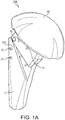
- Humeral component 100 is part of a modular humeral prosthesis 200 shown in FIG. 1(a) in the final assembly with a spherical head 50.
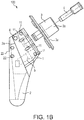
- Humeral component 100 is detailed in FIGS. 1(b)-3(e) and includes stem 2 (stem module 2), inclination piece 1 (neck 1), trunion 3 (coupling adapter 3), version locking screw 4, inclination locking screw 5 and pin 6. Details of at least some of the elements of humeral component 100 of FIG. 1(b) are provided, for example, in U.S. Patent 8,323,347 issued December 4, 2012 .
- stem 2 is adapted to be introduced into a patient's humerus, the stem having a body with a length L and a width W, and a first plurality of through holes 22 (suture eyelets 22) provided laterally within the body and along the length.
- the inclination component 1 includes a first opening to provide access to a screw to set and fix a position of the inclination component at an inclination angle, the inclination component further including a second plurality of holes 11 (suture eyelets 11) provided within the inclination component.
- the coupling adapter 3 includes means for setting a version.
- the spherical head 50 including means for setting and fixing a radial offset, wherein the stem interfaces with the coupling adapter, and the coupling adapter interfaces with the spherical head.
- Stem 2 features a shank (body) with a longitudinal axis 2b and a length L ( FIG. 1(c) ) and having an upper shank portion 2a and a pin 6 that hinges inclination component or inclination piece 1 (neck 1) to the rest of the stem module 2.
- Inclination component 1 fits over the upper shank portion and pivots on the pin through an inclination angle a as detailed and explained in U.S. Patent 8,323,347 .
- Stem 2 is also provided with a first plurality of through holes 22 (first openings or fenestrations or eyelets 22) located within the upper shank portion 2a and disposed in a direction about parallel to the longitudinal axis 2b of the stem.
- the first plurality of through holes 22 includes two lateral holes 22 (as shown in FIGS. 1(a)-1(d) ) that allow passing of a flexible material (for example, suture) therethrough.
- the first plurality of holes 22 includes suture holes or eyelets that allow suture to pass therethrough and form a suture bridge of a reinforced subscapularis repair, as detailed below with reference to FIGS. 5(a)-5(c) .
- the inclination component 1 (neck 1) includes an opening that provides access to a screw (shown in dotted line in FIG. 1(b) as inclination screw 5).
- the screw is advanced and locked in frictional engagement with opposing inside surfaces of the inclination component 1.
- the screw is advanced by turning sufficiently to fix the position of the inclination component 1 at a desired inclination angle.
- the inclination component 1 (neck 1) also includes an opening for engaging trunion 3 (coupling adapter 3) with version locking screw 4.
- the inclination component 1 (neck 1) is further provided with a second plurality of through holes 11 (second openings or fenestrations or eyelets 11) located within the neck, as shown in FIGS. 1(a) and 1(d) , and extending in a direction about parallel to longitudinal axis 1b of the inclination component 1.
- the second plurality of through holes 11 includes four holes 11 that allow passing of a flexible material (for example, four suture strands) therethrough.
- the second plurality of holes 11 includes suture holes that, together with the first plurality of suture holes 22, allow multiple sutures to pass therethrough and in between and form a suture bridge of reinforced subscapularis repairs, as detailed below with reference to FIGS. 5(a)-5(c) .
- Humeral component 100 also includes coupling adapter or trunion 3.
- the trunion or coupling adapter 3 is paired with the inclination component 1.
- the coupling adapter 3 includes an adapter plate 3a (shown in FIG. 1(b) ).
- An access opening through the adapter plate 3a provides access to the inclination-angle locking screw 5.
- a male Morse taper 3b ( FIG. 1(b) ) extends from one side of adapter plate 3a. Morse taper 3b locks into a female Morse taper formed in spherical head 50 ( FIG. 1(a) ). Version is adjusted by pivoting adapter plate 3a with respect to inclination component 1.
- Radial offset is adjusted by rotating the spherical head 50 around male Morse taper 3b with respect to trunion 3 (coupling adapter 3). The components will pivot through different angles of retroversion and anteversion. The radial offset is fixed in position by the locking interaction of the complementary Morse taper features.
- stem 2 provided with the first plurality of through holes 22 is a mini stem (short stem) that provides a stable subscapularis repair when is inserted into a resected humerus.
- the mini stem 2 has a length L ( FIG. 1(c) ) of about 60mm with two suture holes 22 for subscapularis repair and supraspinatus repair incorporated into the stem.
- the mini stem is designed to facilitate ease of revision and to provide a universal platform to restore/accommodate proximal humeral anatomy, as detailed below.
- a method of exemplary shoulder and soft tissue repair with the prosthesis 200 is detailed with reference to FIGS. 4(a)-5(c) below.
- the humeral component 100 has a design that allows it to account for anatomical variations of the proximal humerus commonly encountered by the surgeon. Variable adjustment with respect to the inclination angle, version and head offset are features critical to reconstruction of the proximal humerus.
- the simplified design of the humeral component allows the surgeon to adapt the humeral stem and articular surface to the position that best represents the patient's normal anatomy. All of the adjustments can be made intraoperatively with the implant in the humeral canal. This unique feature allows the surgeon to more accurately recreate the normal anatomical relationships of the shoulder joint. With anatomic restoration of the humerus and glenoid, soft tissue balancing of the rotator cuff is more accurate, allowing for improved functional outcome.
- humeral stem length accounts for various anatomical and revision scenarios that may be encountered.
- the implant provides at least the following features: variable inclination, version and offset; package-to-canal design (anatomic restoration in situ); eccentric humeral heads; multiple head diameters and heights for precise anatomic reconstruction; removable trunion for simplified revision; multiple suture eyelets for subscapularis and lesser tuberosity repair techniques.
- a method of shoulder arthoplasty comprises inter alia the steps of: perform a free cut by the surgeon along the margins of the proximal humerus articular surface while maintaining the patient's articular inclination and version; release the subscapularis; release the anterior and inferior glenohumeral capsule; resect the humeral head; expose the glenoid; prepare the humeral head; prepare the glenoid and implant the keel glenoid implant; prepare the glenoid and implant the pegged glenoid; implant the humeral stem; and close the wound by attaching soft tissue to the humeral stem and inclination component (employing eyelets 11, 22).
- FIGS. 4(a)-4(j) illustrate exemplary steps of a method of implanting the humeral stem and inclination component of the system 200 of the present invention (and prior to wound closure):
- FIGS. 4(a)-4(c) Once the resection protector has been removed, the humeral implant 100 is manually opened to its maximum position ( FIG. 4(b) ) and the stem 2 is inserted into the humeral canal of resected humerus 250 ( FIG. 4(c) ).
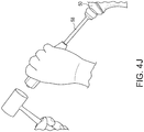
- FIG. 4(d) A pointed stem impactor 51 is placed into the dimple on the lateral portion of the stem 2. The stem is impacted as far as possible; change to the angled morse taper stem impactor.
- FIGS. 4(e) and 4(f) An angled morse taper stem impactor 53 is placed over the morse taper and impaction is completed. The inclination angle remains free while the stem 2 is impacted into the humerus 250 ( FIG. 4(f) ). The inclination angle is established when the flange contacts the humeral surface and is fully seated. For cemented application, the surgeon may select a humeral stem one size smaller than the canal preparation.
- FIG. 4(g) The inferior locking screw 31 located on the medial portion of the trunion 3 is tightened.
- the inferior (inclination) locking screw should be locked before the superior (version) screw is locked.
- FIGS. 4(h) and 4 (h') A torque driver 54 is used to lock the version (superior) screw 33 located on the morse taper of the humeral stem. The surgeon should ensure that the set screw is properly tightened by visually confirming that the "SUP" mark 56 ( FIG. 4 (h')) is rotated to the indicator line on the torque driver 54.
- FIG. 4(j) After the trial reduction, the trial head 57 is removed and an implant head 50 is impacted onto the humeral stem 2 using the head impactor 58.
- wound closure is conducted (for example, by a Subscapularis Apex Bridge Repair (SABER) technique) to employ the suture holes in the proximal body of the stem (for soft tissue repair and subscapularis closure).
- SABER Subscapularis Apex Bridge Repair
- Wound closure begins by removing any remaining soft tissue or bony debris. Hemostasis may be obtained with electrocautery.
- the initial focus of wound closure is the repair of the subscapularis tendon 80.
- the first step of the repair is reattaching the superior lateral edge of the subscapularis to the anterior lateral edge of the supraspinatus directly over the bicipital groove. This is performed with a plurality of flexible strands such as #2 FiberWire® sutures.
- the tendon is held in an anatomic position.
- a total of eight sutures, four #2 FiberWire® sutures for the tendon-to-tendon repair, and four #5 FiberWire® sutures for a tendon-to-bone repair are used for a secure subscapularis repair. This will allow for an early range of motion program and minimize the risk of subscapularis rupture.
- the deltoid and pectoralis major muscle may be repaired with a side-to-side closure using another flexible strand such as a #1 absorbable suture.
- the subcutaneous layer is repaired with an absorbable suture and, finally, another suture is used for the skin closure.
- FIGS. 5(a)-5(c) illustrate schematic steps of tying sutures through the suture eyelets 11, 22 of the prosthesis 200 of the present invention and according to an exemplary SABER technique to obtain final repair 300 ( FIG. 5(c) ).
- Trial heads 57 verify proper head size, head offset, shoulder motion, and stability prior to impacting the actual head component.
- the repair 300 is then evaluated by externally rotating the arm with the arm adducted.
- the degree of external rotation achieved without stressing the repair is noted for post-operative therapy limitations.
- the humeral component 100 of the present invention which is provided with suture holes 22, 11 incorporated into stem 2 and inclination component 1 may be employed for exemplary subscapularis and supraspinatus repairs, and SST repairs.
- the stem has a length of about 60 mm.
- suture eyelets for subscapularis and supraspinatus repairs are incorporated at least into the inclination components (and preferably both into the inclination component and also the stem).
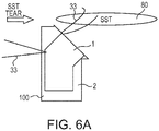
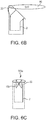
- FIGS. 6(a)-6(c) illustrate exemplary schematic steps of a method of suture bridge repair with humeral prosthesis 100 with lateral holes 22 and medial holes 11 and flexible strand 33 (suture 33).
- the steps refer to an SST repair 300a (Simple Shoulder Test repair 300a) with a schematic humeral component 100 and illustrate how the SST repair is conducted with suture bridge configuration 133 ( FIG. 6(c) ) using anterior and posterior superior-lateral holes.
- FIG. 6(c) shows a lateral view of the final, completed SST repair 300.
- Multiple suture eyelets 11, 22 allow passing of flexible strands 33 (suture strands 33) and more optimal and anatomical locations and repairs for subscapularis and lesser tuberosity attachment.
- the repair may have vertical, horizontal and crossed sutures 33 for compression of soft tissue 80.
- FIGS. 7(a) and 7(b) illustrate prosthetic 200a with another mini stem (short stem) 220 of the present invention that provides a stable subscapularis repair and is inserted into resected humerus 250.
- Stem 220 is provided with a plurality of suture anchor screw holes 222 incorporated into the stem (into upper shank portion 220a of the stem) for receiving a suture anchor to attach tissue.
- FIG. 7(a) also shows an X box/bridge type repair 300b (a suturing pattern with an X configuration) of the subscapularis 80 with two exemplary rows of compression using fixation devices 55 (for example, anchors 55) with suture 33 (for example, #2 FiberWire® suture 33).
- This embodiment allows at least part of the holes to be used with suture anchors to attach at least one flexible strand (at least one suture strand, for example) and tissue.
- Mini stem 2, 220 of the present invention may be reusable, may be used with osteotomy, tenotomy and/or labral repairs and may peel off (take down).
- the flexible material 33 may be employed for additional biceps repairs as well and if desired.
- the mini stem 2, 220 is designed to facilitate ease of revision and to provide a universal platform to restore/accommodate proximal humeral anatomy, as detailed below.
- An exemplary method of shoulder repair with short stem 220 of FIGS. 7(a) and 7(b) includes inter alia the steps of: (i) use a targeting device placed on the Morse taper 3b to insert screw; (ii) anchor targeting device into screw holes for version/inclination; and (iii) drill guide and insertion guide for screws (anchors 55).
- the technique may be used to revise failed subscapularis repairs.
- Any type of flexible material or suture may be passed through the eyelets 11, 22 to complete the various soft tissue repairs.
- Flexible strands or cords 33 may be made of any known suture construct, such as multifilament, braided, knitted, woven suture, or including fibers of ultrahigh molecular weight polyethylene (UHMWPE) or the FiberWire® suture (disclosed in U.S. Patent No. 6,716,234 ).
- FiberWire® suture is formed of an advanced, high-strength fiber material, namely ultrahigh molecular weight polyethylene (UHMWPE), sold under the tradenames Spectra (Honeywell) and Dyneema (DSM), braided with at least one other fiber, natural or synthetic, to form lengths of suture material.
- the preferred FiberWire® suture includes a core within a hollow braided construct, the core being a twisted yarn of UHMWPE.
- the strands may be also formed of a stiff material, or combination of stiff and flexible materials, depending on the intended application.
- the strands may be also coated and/or provided in different colors.
Description
- The present invention relates to a shoulder arthroplasty system for surgical reconstitution of the shoulder and, in particular, to prosthetic replacement of the humerus.
- Instability and other maladies of human joints, such as arthrosis or fracture, can be sufficiently acute that prosthetic replacement of compromised joint features may be indicated. For example, in shoulder reconstruction, the humeral head may be replaced by first resecting the humeral head from the humerus and then installing a humeral prosthetic at the resection.
- Various prostheses have been designed to mimic a portion of the joint, or joint region, being replaced. A shoulder prosthesis, for example, includes a stem to be anchored in the humeral canal and a hemispherical head to be positioned within the glenoid cavity of the scapula. The more-recently devised shoulder prostheses generally are modular systems which may include an articulating member (articulating inclination block component) that allows flexibility with respect to either the tilt angle or the radial offset between the head and stem. The features of the preamble of
claim 1 are known fromUS 8 323 347 B2 . - There is a need for a shoulder arthroplasty system with suture holes provided in the articulating member (inclination piece or articulating inclination block component). Also needed is a fenestrated humeral prosthesis with suture holes that are provided in a shorter, fenestrated stem for soft tissue and fracture repairs. Also needed are methods of addressing the non-bony reattachment of the subscapularis and lesser tuberosity during a total shoulder arthroplasty. An improved modular shoulder arthroplasty system that is designed to address any or all of osteoarthritis, trauma and cuff tear arthropathy is also needed.
- The present invention provides a novel prosthetic assembly for prosthetic and surgical methods for reconstitution of a joint, with special applications to the shoulder joint. The prosthetic assembly includes a fenestrated humeral prosthesis provided with a short stem having a stem body and inclination block with a plurality of holes (fenestrations or multiple suture eyelets) for subscapularis, supraspinatus and lesser tuberosity repairs.
- In an exemplary embodiment, the fenestrated humeral prosthesis includes an inclination block (an articulating inclination block component) of the humeral stem that is provided with a plurality of holes (suture holes or suture eyelets). The stem is also provided with suture holes in the proximal body for soft tissue repair and subscapularis closure. The unique configuration of the suture holes/eyelets provides the user (surgeon) with more optimal and anatomical locations for subscapularis and lesser tuberosity attachment.
- Other features and advantages of the present invention will become apparent from the following description of the invention which refers to the accompany drawings.
-
-
FIG. 1(a) illustrates an exemplary shoulder prosthesis of the present invention (provided with suture holes incorporated into stem and inclination block, for subscapularis, supraspinatus, biceps and lesser tuberosity repairs). -
FIG. 1(b) illustrates an expanded view of the humeral component of the shoulder prosthesis ofFIG. 1(a) . -
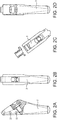
FIG. 1(c) illustrates a side view of the stem and inclination piece of the humeral component ofFIG. 1(b) . -
FIG. 1(d) illustrates a lateral view of the stem and inclination piece ofFIG. 1(b) . -
FIGS. 2(a)-2(d) illustrate additional views of the humeral stem of the prosthesis ofFIG. 1(a) . -
FIGS. 3(a)-3(e) illustrate additional views of the inclination piece of the prosthesis ofFIG. 1(a) . -
FIGS. 4(a)-4(j) illustrate subsequent steps of a method of shoulder repair with the humeral component ofFIG. 1(b) . -
FIGS. 5(a)-5(c) illustrate a SABER repair (Subscapularis Apex Bridge Repair or SABER technique) with subscapularis repair and with the exemplary humeral component ofFIG. 1(b) and after the humeral stem implantation. -
FIGS. 6(a)-6(c) illustrate exemplary schematic steps of a method of suture bridge repair according to another embodiment of the present invention. -
FIG. 7(a) illustrates a short stem (mini stem) humeral prosthesis according to another embodiment of the present invention (and attached to humerus). -
FIG. 7(b) illustrates a schematic view of the short stem prosthesis ofFIG. 7(a) . - In the following detailed description, reference is made to various specific embodiments in which the invention may be practiced. These embodiments are described with sufficient detail to enable those skilled in the art to practice the invention, and it is to be understood that other embodiments may be employed, and that structural and logical changes may be made without departing from the present invention.
- The present invention provides a prosthetic assembly for prosthetic and surgical methods for reconstitution of a joint, with special applications to the shoulder joint. The prosthetic assembly includes a fenestrated humeral prosthesis provided with a short stem having a stem body with a plurality of holes or fenestrations (first suture holes or suture eyelets) for subscapularis and supraspinatus repairs incorporated into the short stem. The suture holes provided in the stem body preferably address soft tissue repairs and not fracture repairs. The fenestrated humeral prosthesis also includes an inclination block (an articulating inclination block component) of the humeral stem that is provided with another plurality of holes or fenestrations (second suture holes or suture eyelets). The unique configuration of the suture holes provides the user (surgeon) with more optimal and anatomical locations for subscapularis and lesser tuberosity attachment.
- The present description also discloses a method of conducting surgery by providing a prosthetic assembly comprising a fenestrated humeral prosthesis with attachment points (suture holes) for flexible material (for example, suture, suture tape, suture chain or FiberWire® suture) provided within the body of the stem and within the articulating inclination block. In an exemplary embodiment, a SABER shoulder repair (Subscapularis Apex Bridge Repair or SABER technique) has been developed to take advantage of these suture eyelets (holes) and to incorporate subscapularis, supraspinatus and/or biceps repairs with shoulder arthoplasty.
- Referring now to the drawings, where like elements are designated by like reference numerals,
FIGS. 1(a)-7(b) illustrate an exemplaryhumeral prosthesis humeral component 100 according to exemplary embodiments of the present invention. -
Humeral component 100 is part of a modularhumeral prosthesis 200 shown inFIG. 1(a) in the final assembly with aspherical head 50.Humeral component 100 is detailed inFIGS. 1(b)-3(e) and includes stem 2 (stem module 2), inclination piece 1 (neck 1), trunion 3 (coupling adapter 3),version locking screw 4,inclination locking screw 5 andpin 6. Details of at least some of the elements ofhumeral component 100 ofFIG. 1(b) are provided, for example, inU.S. Patent 8,323,347 issued December 4, 2012 . - As detailed below with reference to
FIGS. 4(a)-4(j) ,stem 2 is adapted to be introduced into a patient's humerus, the stem having a body with a length L and a width W, and a first plurality of through holes 22 (suture eyelets 22) provided laterally within the body and along the length. Theinclination component 1 includes a first opening to provide access to a screw to set and fix a position of the inclination component at an inclination angle, the inclination component further including a second plurality of holes 11 (suture eyelets 11) provided within the inclination component. Thecoupling adapter 3 includes means for setting a version. Thespherical head 50 including means for setting and fixing a radial offset, wherein the stem interfaces with the coupling adapter, and the coupling adapter interfaces with the spherical head. -
Stem 2 features a shank (body) with a longitudinal axis 2b and a length L (FIG. 1(c) ) and having anupper shank portion 2a and apin 6 that hinges inclination component or inclination piece 1 (neck 1) to the rest of thestem module 2.Inclination component 1 fits over the upper shank portion and pivots on the pin through an inclination angle a as detailed and explained inU.S. Patent 8,323,347 . -
Stem 2 is also provided with a first plurality of through holes 22 (first openings or fenestrations or eyelets 22) located within theupper shank portion 2a and disposed in a direction about parallel to the longitudinal axis 2b of the stem. In an exemplary-only embodiment, the first plurality of throughholes 22 includes two lateral holes 22 (as shown inFIGS. 1(a)-1(d) ) that allow passing of a flexible material (for example, suture) therethrough. In an exemplary-only embodiment, the first plurality ofholes 22 includes suture holes or eyelets that allow suture to pass therethrough and form a suture bridge of a reinforced subscapularis repair, as detailed below with reference toFIGS. 5(a)-5(c) . - The inclination component 1 (neck 1) includes an opening that provides access to a screw (shown in dotted line in
FIG. 1(b) as inclination screw 5). The screw is advanced and locked in frictional engagement with opposing inside surfaces of theinclination component 1. The screw is advanced by turning sufficiently to fix the position of theinclination component 1 at a desired inclination angle. The inclination component 1 (neck 1) also includes an opening for engaging trunion 3 (coupling adapter 3) withversion locking screw 4. - The inclination component 1 (neck 1) is further provided with a second plurality of through holes 11 (second openings or fenestrations or eyelets 11) located within the neck, as shown in
FIGS. 1(a) and1(d) , and extending in a direction about parallel tolongitudinal axis 1b of theinclination component 1. In an exemplary-only embodiment, the second plurality of throughholes 11 includes fourholes 11 that allow passing of a flexible material (for example, four suture strands) therethrough. In an exemplary-only embodiment, the second plurality ofholes 11 includes suture holes that, together with the first plurality ofsuture holes 22, allow multiple sutures to pass therethrough and in between and form a suture bridge of reinforced subscapularis repairs, as detailed below with reference toFIGS. 5(a)-5(c) . -
Humeral component 100 also includes coupling adapter ortrunion 3. The trunion orcoupling adapter 3 is paired with theinclination component 1. Thecoupling adapter 3 includes anadapter plate 3a (shown inFIG. 1(b) ). An access opening through theadapter plate 3a provides access to the inclination-angle locking screw 5. Amale Morse taper 3b (FIG. 1(b) ) extends from one side ofadapter plate 3a.Morse taper 3b locks into a female Morse taper formed in spherical head 50 (FIG. 1(a) ). Version is adjusted by pivotingadapter plate 3a with respect toinclination component 1. Radial offset is adjusted by rotating thespherical head 50 aroundmale Morse taper 3b with respect to trunion 3 (coupling adapter 3). The components will pivot through different angles of retroversion and anteversion. The radial offset is fixed in position by the locking interaction of the complementary Morse taper features. - In a preferred embodiment,
stem 2 provided with the first plurality of throughholes 22 is a mini stem (short stem) that provides a stable subscapularis repair when is inserted into a resected humerus. In an exemplary embodiment, themini stem 2 has a length L (FIG. 1(c) ) of about 60mm with twosuture holes 22 for subscapularis repair and supraspinatus repair incorporated into the stem. The mini stem is designed to facilitate ease of revision and to provide a universal platform to restore/accommodate proximal humeral anatomy, as detailed below. - A method of exemplary shoulder and soft tissue repair with the
prosthesis 200 is detailed with reference toFIGS. 4(a)-5(c) below. - The
humeral component 100 has a design that allows it to account for anatomical variations of the proximal humerus commonly encountered by the surgeon. Variable adjustment with respect to the inclination angle, version and head offset are features critical to reconstruction of the proximal humerus. The simplified design of the humeral component allows the surgeon to adapt the humeral stem and articular surface to the position that best represents the patient's normal anatomy. All of the adjustments can be made intraoperatively with the implant in the humeral canal. This unique feature allows the surgeon to more accurately recreate the normal anatomical relationships of the shoulder joint. With anatomic restoration of the humerus and glenoid, soft tissue balancing of the rotator cuff is more accurate, allowing for improved functional outcome. In addition, humeral stem length accounts for various anatomical and revision scenarios that may be encountered. - The implant provides at least the following features: variable inclination, version and offset; package-to-canal design (anatomic restoration in situ); eccentric humeral heads; multiple head diameters and heights for precise anatomic reconstruction; removable trunion for simplified revision; multiple suture eyelets for subscapularis and lesser tuberosity repair techniques.
- A method of shoulder arthoplasty comprises inter alia the steps of: perform a free cut by the surgeon along the margins of the proximal humerus articular surface while maintaining the patient's articular inclination and version; release the subscapularis; release the anterior and inferior glenohumeral capsule; resect the humeral head; expose the glenoid; prepare the humeral head; prepare the glenoid and implant the keel glenoid implant; prepare the glenoid and implant the pegged glenoid; implant the humeral stem; and close the wound by attaching soft tissue to the humeral stem and inclination component (employing
eyelets 11, 22). -
FIGS. 4(a)-4(j) illustrate exemplary steps of a method of implanting the humeral stem and inclination component of thesystem 200 of the present invention (and prior to wound closure): -
FIGS. 4(a)-4(c) : Once the resection protector has been removed, thehumeral implant 100 is manually opened to its maximum position (FIG. 4(b) ) and thestem 2 is inserted into the humeral canal of resected humerus 250 (FIG. 4(c) ). -
FIG. 4(d) : A pointed stem impactor 51 is placed into the dimple on the lateral portion of thestem 2. The stem is impacted as far as possible; change to the angled morse taper stem impactor. -
FIGS. 4(e) and 4(f) : An angled morse taper stemimpactor 53 is placed over the morse taper and impaction is completed. The inclination angle remains free while thestem 2 is impacted into the humerus 250 (FIG. 4(f) ). The inclination angle is established when the flange contacts the humeral surface and is fully seated. For cemented application, the surgeon may select a humeral stem one size smaller than the canal preparation. -
FIG. 4(g) : Theinferior locking screw 31 located on the medial portion of thetrunion 3 is tightened. The inferior (inclination) locking screw should be locked before the superior (version) screw is locked. -
FIGS. 4(h) and4 (h'): Atorque driver 54 is used to lock the version (superior)screw 33 located on the morse taper of the humeral stem. The surgeon should ensure that the set screw is properly tightened by visually confirming that the "SUP" mark 56 (FIG. 4 (h')) is rotated to the indicator line on thetorque driver 54. -
FIGS. 4(i) and4 (i'): Anappropriate trial head 57 is attached and the trial driver is used to adjust offset. A trial reduction is performed. The position of maximum offset is designated by a line on the surface of the trial head. -
FIG. 4(j) : After the trial reduction, thetrial head 57 is removed and animplant head 50 is impacted onto thehumeral stem 2 using thehead impactor 58. - Subsequent to the humeral stem implantation, wound closure is conducted (for example, by a Subscapularis Apex Bridge Repair (SABER) technique) to employ the suture holes in the proximal body of the stem (for soft tissue repair and subscapularis closure).
- Wound closure begins by removing any remaining soft tissue or bony debris. Hemostasis may be obtained with electrocautery. The initial focus of wound closure is the repair of the
subscapularis tendon 80. To ensure that the subscapularis tendon is repaired to its anatomic position, the first step of the repair is reattaching the superior lateral edge of the subscapularis to the anterior lateral edge of the supraspinatus directly over the bicipital groove. This is performed with a plurality of flexible strands such as #2 FiberWire® sutures. By securing the superior lateral edge of thesubscapularis 80 at the beginning of the repair, the tendon is held in an anatomic position. - Four flexible strands (for example, four braided #5 FiberWire® sutures) which were placed at the rim of the osteotomy site are individually passed through the
subscapularis tendon 80 separated by approximately 1 cm. The sutures can be passed with a Mason-Allen configuration to improve security of the suture in the tendon. The sutures are tied beginning superiorly and proceeding inferiorly.Additional # 2 FiberWire® sutures are placed in between each of the #5 FiberWire® sutures for a tendon-to-tendon repair, reattaching the subscapularis tendon to the remaining fibers in the lesser tuberosity. A total of eight sutures, four #2 FiberWire® sutures for the tendon-to-tendon repair, and four #5 FiberWire® sutures for a tendon-to-bone repair are used for a secure subscapularis repair. This will allow for an early range of motion program and minimize the risk of subscapularis rupture. - The deltoid and pectoralis major muscle may be repaired with a side-to-side closure using another flexible strand such as a #1 absorbable suture. The subcutaneous layer is repaired with an absorbable suture and, finally, another suture is used for the skin closure.
-
FIGS. 5(a)-5(c) illustrate schematic steps of tying sutures through the suture eyelets 11, 22 of theprosthesis 200 of the present invention and according to an exemplary SABER technique to obtain final repair 300 (FIG. 5(c) ). -
- 1) Two holes are drilled vertically in the biceps groove for passage of the lateral suture limbs.
- 2) Two flexible strands (for example, #2 FiberWire® sutures) are passed through the lateral holes yielding four suture limbs labeled A through D from superior to inferior.
- 3) Four flexible strands (for example, #2 FiberWire® sutures) are passed through the medial holes yielding eight suture limbs labeled 1 through 8 from superior to inferior.
- 4) Limbs A&B are passed through the superior hole from the intramedullary canal out. Likewise, limbs C&D are passed through the inferior hole from the intramedullary canal out.
- 5) All strands are held out to length on tension as the stem is implanted and impacted with the straight impactor followed by the trunion impactor which places the trunion flush to the osteotomy surface.
- The inclination (inferior) and version (superior) screws 31, 33 are then tightened with the torque driver.
- Trial heads 57 verify proper head size, head offset, shoulder motion, and stability prior to impacting the actual head component.
-
- 6)
Suture limbs 1 through 8 are evenly placed through the medial aspect of thesubscapularis tendon 80 from superior to inferior. - 7) The sutures are then tied in the follow sequence (
FIG. 5(c) ):- a. 1 to A
- b. 8 to D
- c. 4 to C
- d. 5 to B
- e. 2 to 3 (these sutures will compress the tendon repair to the LT)
- f. 6 to 7 (these sutures will compress the tendon repair to the LT)
- The
repair 300 is then evaluated by externally rotating the arm with the arm adducted. The degree of external rotation achieved without stressing the repair is noted for post-operative therapy limitations. - In summary, as described above, the
humeral component 100 of the present invention which is provided withsuture holes stem 2 andinclination component 1 may be employed for exemplary subscapularis and supraspinatus repairs, and SST repairs. The stem has a length of about 60 mm. As detailed above, suture eyelets for subscapularis and supraspinatus repairs are incorporated at least into the inclination components (and preferably both into the inclination component and also the stem). -
FIGS. 6(a)-6(c) illustrate exemplary schematic steps of a method of suture bridge repair withhumeral prosthesis 100 withlateral holes 22 andmedial holes 11 and flexible strand 33 (suture 33). The steps refer to anSST repair 300a (SimpleShoulder Test repair 300a) with a schematichumeral component 100 and illustrate how the SST repair is conducted with suture bridge configuration 133 (FIG. 6(c) ) using anterior and posterior superior-lateral holes.FIG. 6(c) shows a lateral view of the final, completedSST repair 300. Multiple suture eyelets 11, 22 allow passing of flexible strands 33 (suture strands 33) and more optimal and anatomical locations and repairs for subscapularis and lesser tuberosity attachment. The repair may have vertical, horizontal and crossedsutures 33 for compression ofsoft tissue 80. -
FIGS. 7(a) and 7(b) illustrate prosthetic 200a with another mini stem (short stem) 220 of the present invention that provides a stable subscapularis repair and is inserted into resectedhumerus 250.Stem 220 is provided with a plurality of suture anchor screw holes 222 incorporated into the stem (intoupper shank portion 220a of the stem) for receiving a suture anchor to attach tissue.FIG. 7(a) also shows an X box/bridge type repair 300b (a suturing pattern with an X configuration) of thesubscapularis 80 with two exemplary rows of compression using fixation devices 55 (for example, anchors 55) with suture 33 (for example, #2 FiberWire® suture 33). This embodiment allows at least part of the holes to be used with suture anchors to attach at least one flexible strand (at least one suture strand, for example) and tissue. -
Mini stem mini stem - An exemplary method of shoulder repair with
short stem 220 ofFIGS. 7(a) and 7(b) includes inter alia the steps of: (i) use a targeting device placed on theMorse taper 3b to insert screw; (ii) anchor targeting device into screw holes for version/inclination; and (iii) drill guide and insertion guide for screws (anchors 55). The technique may be used to revise failed subscapularis repairs. - Any type of flexible material or suture (such as FiberWire®, FiberTape®, FiberChain®, etc.) may be passed through the
eyelets - Flexible strands or
cords 33 may be made of any known suture construct, such as multifilament, braided, knitted, woven suture, or including fibers of ultrahigh molecular weight polyethylene (UHMWPE) or the FiberWire® suture (disclosed inU.S. Patent No. 6,716,234 ). FiberWire® suture is formed of an advanced, high-strength fiber material, namely ultrahigh molecular weight polyethylene (UHMWPE), sold under the tradenames Spectra (Honeywell) and Dyneema (DSM), braided with at least one other fiber, natural or synthetic, to form lengths of suture material. The preferred FiberWire® suture includes a core within a hollow braided construct, the core being a twisted yarn of UHMWPE. - The strands may be also formed of a stiff material, or combination of stiff and flexible materials, depending on the intended application. The strands may be also coated and/or provided in different colors.
- Although the present invention has been described in relation to particular embodiments thereof, many other variations and modifications and other uses will become apparent to those skilled in the art. While the present embodiments are described herein with reference to illustrative figures for particular applications, it should be understood that the embodiments are not limited thereto. Those having ordinary skill in the art and access to the teachings provided herein will recognize additional modifications, applications, embodiments and substitution of equivalents falling within the scope of the presented embodiments. Accordingly, the embodiments are not to be considered as limited by the foregoing description, but by the appended claims.
Claims (9)
- A humeral prosthetic, comprising:a stem (2) adapted to be introduced into a patient's humerus, the stem (2) having a body with a longitudinal axis (2b);an inclination component (1) including a first opening to provide access to a screw to set and fix a position of the inclination component (1) at an inclination angle;a coupling adapter (3) including means for setting a version; anda spherical head (50) including means for setting and fixing a radial offset, wherein the stem (2) interfaces with the coupling adapter (3),and the coupling adapter (3) interfaces with the spherical head (50);said humeral prosthetic being characterized in that; the inclination component (1) further includes a second plurality of holes (11) provided within the inclination component (1), extending in a direction about parallel to a longitudinal axis (1b) of the inclination component (1) and employable for subscapularis, supraspinatus and biceps repairs,and in that the humeral prosthetic comprises a first plurality of through holes (22) provided laterally within an upper portion of the body and about parallel to the longitudinal axis (2b) of the body of the stem (2) and employable for soft tissue repairs and not for fracture repairs.
- The humeral prosthetic of claim 1, wherein the stem (2) has a length of about 60 mm.
- The humeral prosthetic of claim 1, wherein the first plurality of holes (22) are employable for lesser tuberosity repairs.
- The humeral prosthetic of claim 1, wherein the coupling adaptor comprises a trunion and a version locking screw (4).
- The humeral prosthetic of claim 4, wherein the trunion has a component designed to frictionally engage at least one wall of an opening provided within the inclination component (1).
- The humeral prosthetic of claim 1, wherein the humeral stem (2) comprises a shank with an upper shank portion (2a) and the first plurality of holes or openings (22) provided within the upper shank portion (2a) and incorporated within the stem (2), the plurality of holes or openings (22) being configured to receive a plurality of fixation devices to attach a flexible strand to soft tissue.
- The humeral prosthetic of claim 6, wherein the fixation devices are suture anchors, the flexible strand is suture, and the soft tissue is at least one of subscapularis, supraspinatus or biceps.
- The humeral prosthetic of claim 7, wherein the fixation devices are suture anchors and the flexible strand is suture, and wherein the suture anchors and the suture form a suture pattern repair having an X configuration.
- The humeral prosthetic of claim 6, wherein the shank has a length of about 60 mm.
Applications Claiming Priority (1)
| Application Number | Priority Date | Filing Date | Title |
|---|---|---|---|
| US201361765160P | 2013-02-15 | 2013-02-15 |
Publications (3)
| Publication Number | Publication Date |
|---|---|
| EP2767262A2 EP2767262A2 (en) | 2014-08-20 |
| EP2767262A3 EP2767262A3 (en) | 2014-09-10 |
| EP2767262B1 true EP2767262B1 (en) | 2018-09-26 |
Family
ID=50101775
Family Applications (1)
| Application Number | Title | Priority Date | Filing Date |
|---|---|---|---|
| EP14155167.1A Active EP2767262B1 (en) | 2013-02-15 | 2014-02-14 | Humeral prosthesis |
Country Status (2)
| Country | Link |
|---|---|
| US (1) | US9402730B2 (en) |
| EP (1) | EP2767262B1 (en) |
Families Citing this family (33)
| Publication number | Priority date | Publication date | Assignee | Title |
|---|---|---|---|---|
| US7896883B2 (en) | 2000-05-01 | 2011-03-01 | Arthrosurface, Inc. | Bone resurfacing system and method |
| US6610067B2 (en) | 2000-05-01 | 2003-08-26 | Arthrosurface, Incorporated | System and method for joint resurface repair |
| US6520964B2 (en) | 2000-05-01 | 2003-02-18 | Std Manufacturing, Inc. | System and method for joint resurface repair |
| US8388624B2 (en) | 2003-02-24 | 2013-03-05 | Arthrosurface Incorporated | Trochlear resurfacing system and method |
| EP1845890A4 (en) | 2003-11-20 | 2010-06-09 | Arthrosurface Inc | System and method for retrograde procedure |
| JP2008504107A (en) | 2004-06-28 | 2008-02-14 | アースロサーフィス・インコーポレーテッド | Joint surface replacement system |
| US7828853B2 (en) | 2004-11-22 | 2010-11-09 | Arthrosurface, Inc. | Articular surface implant and delivery system |
| US20110213375A1 (en) | 2006-07-17 | 2011-09-01 | Arthrosurface, Inc. | Tibial Resurfacing System and Method |
| US9358029B2 (en) | 2006-12-11 | 2016-06-07 | Arthrosurface Incorporated | Retrograde resection apparatus and method |
| EP2429429B1 (en) | 2009-04-17 | 2018-07-25 | Arthrosurface Incorporated | Glenoid resurfacing system |
| WO2016154393A1 (en) | 2009-04-17 | 2016-09-29 | Arthrosurface Incorporated | Glenoid repair system and methods of use thereof |
| WO2010121250A1 (en) | 2009-04-17 | 2010-10-21 | Arthrosurface Incorporated | Glenoid resurfacing system and method |
| US9066716B2 (en) | 2011-03-30 | 2015-06-30 | Arthrosurface Incorporated | Suture coil and suture sheath for tissue repair |
| WO2013096746A1 (en) | 2011-12-22 | 2013-06-27 | Arthrosurface Incorporated | System and method for bone fixation |
| DE112013003358T5 (en) | 2012-07-03 | 2015-03-19 | Arthrosurface, Inc. | System and procedure for joint surface replacement and repair |
| WO2014138061A1 (en) | 2013-03-08 | 2014-09-12 | Mayo Foundation For Medical Education And Research | Shoulder prosthesis with variable inclination humeral head component |
| US11071635B2 (en) | 2013-03-08 | 2021-07-27 | Mayo Foundation For Medical Education And Research | Shoulder prosthesis with variable inclination humeral head component |
| US9492200B2 (en) | 2013-04-16 | 2016-11-15 | Arthrosurface Incorporated | Suture system and method |
| US10456264B2 (en) | 2014-01-24 | 2019-10-29 | Tornier, Inc. | Humeral implant anchor system |
| US11607319B2 (en) | 2014-03-07 | 2023-03-21 | Arthrosurface Incorporated | System and method for repairing articular surfaces |
| US10624748B2 (en) | 2014-03-07 | 2020-04-21 | Arthrosurface Incorporated | System and method for repairing articular surfaces |
| US20150250472A1 (en) | 2014-03-07 | 2015-09-10 | Arthrosurface Incorporated | Delivery System for Articular Surface Implant |
| WO2017147618A1 (en) | 2016-02-28 | 2017-08-31 | Consortium Of Focused Orthopedists, Llc | Shoulder arthroplasty implant system |
| US11833055B2 (en) | 2016-02-28 | 2023-12-05 | Integrated Shoulder Collaboration, Inc. | Shoulder arthroplasty implant system |
| US10463499B2 (en) | 2016-03-25 | 2019-11-05 | Tornier, Inc. | Stemless shoulder implant with fixation components |
| US10588752B2 (en) * | 2016-03-29 | 2020-03-17 | Biomet Manufacturing, Llc | Modular bone model |
| WO2018022227A1 (en) | 2016-07-28 | 2018-02-01 | Tornier, Inc. | Stemless prosthesis anchor component |
| CA3108761A1 (en) | 2017-08-04 | 2019-02-07 | Arthrosurface Incorporated | Multicomponent articular surface implant |
| US10898338B1 (en) * | 2018-01-17 | 2021-01-26 | Matthew Budge | Reverse shoulder prosthesis |
| US11000360B2 (en) | 2018-09-14 | 2021-05-11 | Onkos Surgical, Inc. | Systems and methods for attaching soft tissue to an implant |
| US11478358B2 (en) | 2019-03-12 | 2022-10-25 | Arthrosurface Incorporated | Humeral and glenoid articular surface implant systems and methods |
| EP4037617A1 (en) * | 2019-10-01 | 2022-08-10 | Howmedica Osteonics Corporation | Shoulder prosthesis components and assemblies |
| AU2022229902A1 (en) * | 2021-03-04 | 2023-09-21 | Shoulder Innovations, Inc. | Implant with suture retention structure |
Family Cites Families (9)
| Publication number | Priority date | Publication date | Assignee | Title |
|---|---|---|---|---|
| FR2703241B1 (en) | 1993-03-30 | 1995-05-19 | Landanger Landos | Head for modular shoulder and hip prosthesis. |
| IT1317744B1 (en) | 2000-01-28 | 2003-07-15 | Cremascoli Ortho S A | ENDOPROTESIS OF THE SHOULDER FOR FRACTURES OF THE UPPER HUMERUM END. |
| US6398812B1 (en) * | 2000-02-10 | 2002-06-04 | Medidea, Llc | Shoulder prosthesis with anatomic reattachment features |
| US6716234B2 (en) | 2001-09-13 | 2004-04-06 | Arthrex, Inc. | High strength suture material |
| WO2005082291A1 (en) * | 2004-02-05 | 2005-09-09 | Exactech, Inc. | Shoulder prosthesis with humeral fracture stem |
| US20060069445A1 (en) * | 2004-09-27 | 2006-03-30 | Ondrla Jeffrey M | Extended articulation prosthesis adaptor and associated method |
| EP1764065B1 (en) * | 2005-08-25 | 2019-08-14 | Arthrex, Inc. | Shoulder prosthesis |
| GB2440911A (en) * | 2006-08-14 | 2008-02-20 | Keith Borowsky | Shoulder replacement |
| EP2474289A1 (en) * | 2011-01-11 | 2012-07-11 | Arthrex, Inc. | Humeral component of a shoulder prosthesis |
-
2014
- 2014-02-14 EP EP14155167.1A patent/EP2767262B1/en active Active
- 2014-02-14 US US14/181,015 patent/US9402730B2/en active Active
Non-Patent Citations (1)
| Title |
|---|
| None * |
Also Published As
| Publication number | Publication date |
|---|---|
| EP2767262A2 (en) | 2014-08-20 |
| US9402730B2 (en) | 2016-08-02 |
| US20140288657A1 (en) | 2014-09-25 |
| EP2767262A3 (en) | 2014-09-10 |
Similar Documents
| Publication | Publication Date | Title |
|---|---|---|
| EP2767262B1 (en) | Humeral prosthesis | |
| US11911276B2 (en) | Rotatable collar for a prosthesis | |
| US10070967B2 (en) | Orthopaedic implant and method of installing same | |
| US9474618B2 (en) | Method and apparatus for restoring a joint, including the provision and use of a longitudinally-adjustable and rotationally-adjustable joint prosthesis | |
| US10010424B2 (en) | Implant | |
| US20060079963A1 (en) | Semiconstrained shoulder prosthetic for treatment of rotator cuff arthropathy | |
| US8246621B2 (en) | Reamer guide for revision procedure | |
| AU2014262278A1 (en) | Rotatable collar for a prosthesis | |
| Scuderi et al. | Minimally invasive approach for shoulder arthroplasty | |
| CN103025273B (en) | Rotatable collar for prosthese |
Legal Events
| Date | Code | Title | Description |
|---|---|---|---|
| PUAL | Search report despatched |
Free format text: ORIGINAL CODE: 0009013 |
|
| PUAI | Public reference made under article 153(3) epc to a published international application that has entered the european phase |
Free format text: ORIGINAL CODE: 0009012 |
|
| 17P | Request for examination filed |
Effective date: 20140214 |
|
| AK | Designated contracting states |
Kind code of ref document: A2 Designated state(s): AL AT BE BG CH CY CZ DE DK EE ES FI FR GB GR HR HU IE IS IT LI LT LU LV MC MK MT NL NO PL PT RO RS SE SI SK SM TR |
|
| AX | Request for extension of the european patent |
Extension state: BA ME |
|
| AK | Designated contracting states |
Kind code of ref document: A3 Designated state(s): AL AT BE BG CH CY CZ DE DK EE ES FI FR GB GR HR HU IE IS IT LI LT LU LV MC MK MT NL NO PL PT RO RS SE SI SK SM TR |
|
| AX | Request for extension of the european patent |
Extension state: BA ME |
|
| RIC1 | Information provided on ipc code assigned before grant |
Ipc: A61F 2/40 20060101AFI20140801BHEP |
|
| R17P | Request for examination filed (corrected) |
Effective date: 20150306 |
|
| RBV | Designated contracting states (corrected) |
Designated state(s): AL AT BE BG CH CY CZ DE DK EE ES FI FR GB GR HR HU IE IS IT LI LT LU LV MC MK MT NL NO PL PT RO RS SE SI SK SM TR |
|
| GRAP | Despatch of communication of intention to grant a patent |
Free format text: ORIGINAL CODE: EPIDOSNIGR1 |
|
| INTG | Intention to grant announced |
Effective date: 20160818 |
|
| RIN1 | Information on inventor provided before grant (corrected) |
Inventor name: LEDERMAN, EVAN S. Inventor name: GOBEZIE, REUBEN Inventor name: GUEDERIAN, GREGORY A. |
|
| GRAJ | Information related to disapproval of communication of intention to grant by the applicant or resumption of examination proceedings by the epo deleted |
Free format text: ORIGINAL CODE: EPIDOSDIGR1 |
|
| STAA | Information on the status of an ep patent application or granted ep patent |
Free format text: STATUS: REQUEST FOR EXAMINATION WAS MADE |
|
| STAA | Information on the status of an ep patent application or granted ep patent |
Free format text: STATUS: EXAMINATION IS IN PROGRESS |
|
| INTC | Intention to grant announced (deleted) | ||
| 17Q | First examination report despatched |
Effective date: 20170202 |
|
| GRAP | Despatch of communication of intention to grant a patent |
Free format text: ORIGINAL CODE: EPIDOSNIGR1 |
|
| STAA | Information on the status of an ep patent application or granted ep patent |
Free format text: STATUS: GRANT OF PATENT IS INTENDED |
|
| INTG | Intention to grant announced |
Effective date: 20171213 |
|
| GRAJ | Information related to disapproval of communication of intention to grant by the applicant or resumption of examination proceedings by the epo deleted |
Free format text: ORIGINAL CODE: EPIDOSDIGR1 |
|
| STAA | Information on the status of an ep patent application or granted ep patent |
Free format text: STATUS: EXAMINATION IS IN PROGRESS |
|
| INTC | Intention to grant announced (deleted) | ||
| GRAP | Despatch of communication of intention to grant a patent |
Free format text: ORIGINAL CODE: EPIDOSNIGR1 |
|
| STAA | Information on the status of an ep patent application or granted ep patent |
Free format text: STATUS: GRANT OF PATENT IS INTENDED |
|
| INTG | Intention to grant announced |
Effective date: 20180530 |
|
| GRAS | Grant fee paid |
Free format text: ORIGINAL CODE: EPIDOSNIGR3 |
|
| GRAA | (expected) grant |
Free format text: ORIGINAL CODE: 0009210 |
|
| STAA | Information on the status of an ep patent application or granted ep patent |
Free format text: STATUS: THE PATENT HAS BEEN GRANTED |
|
| AK | Designated contracting states |
Kind code of ref document: B1 Designated state(s): AL AT BE BG CH CY CZ DE DK EE ES FI FR GB GR HR HU IE IS IT LI LT LU LV MC MK MT NL NO PL PT RO RS SE SI SK SM TR |
|
| REG | Reference to a national code |
Ref country code: GB Ref legal event code: FG4D |
|
| REG | Reference to a national code |
Ref country code: CH Ref legal event code: EP |
|
| REG | Reference to a national code |
Ref country code: AT Ref legal event code: REF Ref document number: 1045121 Country of ref document: AT Kind code of ref document: T Effective date: 20181015 |
|
| REG | Reference to a national code |
Ref country code: IE Ref legal event code: FG4D |
|
| REG | Reference to a national code |
Ref country code: DE Ref legal event code: R096 Ref document number: 602014032888 Country of ref document: DE |
|
| REG | Reference to a national code |
Ref country code: NL Ref legal event code: MP Effective date: 20180926 |
|
| PG25 | Lapsed in a contracting state [announced via postgrant information from national office to epo] |
Ref country code: LT Free format text: LAPSE BECAUSE OF FAILURE TO SUBMIT A TRANSLATION OF THE DESCRIPTION OR TO PAY THE FEE WITHIN THE PRESCRIBED TIME-LIMIT Effective date: 20180926 Ref country code: RS Free format text: LAPSE BECAUSE OF FAILURE TO SUBMIT A TRANSLATION OF THE DESCRIPTION OR TO PAY THE FEE WITHIN THE PRESCRIBED TIME-LIMIT Effective date: 20180926 Ref country code: FI Free format text: LAPSE BECAUSE OF FAILURE TO SUBMIT A TRANSLATION OF THE DESCRIPTION OR TO PAY THE FEE WITHIN THE PRESCRIBED TIME-LIMIT Effective date: 20180926 Ref country code: SE Free format text: LAPSE BECAUSE OF FAILURE TO SUBMIT A TRANSLATION OF THE DESCRIPTION OR TO PAY THE FEE WITHIN THE PRESCRIBED TIME-LIMIT Effective date: 20180926 Ref country code: GR Free format text: LAPSE BECAUSE OF FAILURE TO SUBMIT A TRANSLATION OF THE DESCRIPTION OR TO PAY THE FEE WITHIN THE PRESCRIBED TIME-LIMIT Effective date: 20181227 Ref country code: BG Free format text: LAPSE BECAUSE OF FAILURE TO SUBMIT A TRANSLATION OF THE DESCRIPTION OR TO PAY THE FEE WITHIN THE PRESCRIBED TIME-LIMIT Effective date: 20181226 Ref country code: NO Free format text: LAPSE BECAUSE OF FAILURE TO SUBMIT A TRANSLATION OF THE DESCRIPTION OR TO PAY THE FEE WITHIN THE PRESCRIBED TIME-LIMIT Effective date: 20181226 |
|
| REG | Reference to a national code |
Ref country code: LT Ref legal event code: MG4D |
|
| PG25 | Lapsed in a contracting state [announced via postgrant information from national office to epo] |
Ref country code: HR Free format text: LAPSE BECAUSE OF FAILURE TO SUBMIT A TRANSLATION OF THE DESCRIPTION OR TO PAY THE FEE WITHIN THE PRESCRIBED TIME-LIMIT Effective date: 20180926 Ref country code: AL Free format text: LAPSE BECAUSE OF FAILURE TO SUBMIT A TRANSLATION OF THE DESCRIPTION OR TO PAY THE FEE WITHIN THE PRESCRIBED TIME-LIMIT Effective date: 20180926 Ref country code: LV Free format text: LAPSE BECAUSE OF FAILURE TO SUBMIT A TRANSLATION OF THE DESCRIPTION OR TO PAY THE FEE WITHIN THE PRESCRIBED TIME-LIMIT Effective date: 20180926 |
|
| REG | Reference to a national code |
Ref country code: AT Ref legal event code: MK05 Ref document number: 1045121 Country of ref document: AT Kind code of ref document: T Effective date: 20180926 |
|
| PG25 | Lapsed in a contracting state [announced via postgrant information from national office to epo] |
Ref country code: CZ Free format text: LAPSE BECAUSE OF FAILURE TO SUBMIT A TRANSLATION OF THE DESCRIPTION OR TO PAY THE FEE WITHIN THE PRESCRIBED TIME-LIMIT Effective date: 20180926 Ref country code: ES Free format text: LAPSE BECAUSE OF FAILURE TO SUBMIT A TRANSLATION OF THE DESCRIPTION OR TO PAY THE FEE WITHIN THE PRESCRIBED TIME-LIMIT Effective date: 20180926 Ref country code: IT Free format text: LAPSE BECAUSE OF FAILURE TO SUBMIT A TRANSLATION OF THE DESCRIPTION OR TO PAY THE FEE WITHIN THE PRESCRIBED TIME-LIMIT Effective date: 20180926 Ref country code: AT Free format text: LAPSE BECAUSE OF FAILURE TO SUBMIT A TRANSLATION OF THE DESCRIPTION OR TO PAY THE FEE WITHIN THE PRESCRIBED TIME-LIMIT Effective date: 20180926 Ref country code: NL Free format text: LAPSE BECAUSE OF FAILURE TO SUBMIT A TRANSLATION OF THE DESCRIPTION OR TO PAY THE FEE WITHIN THE PRESCRIBED TIME-LIMIT Effective date: 20180926 Ref country code: RO Free format text: LAPSE BECAUSE OF FAILURE TO SUBMIT A TRANSLATION OF THE DESCRIPTION OR TO PAY THE FEE WITHIN THE PRESCRIBED TIME-LIMIT Effective date: 20180926 Ref country code: PL Free format text: LAPSE BECAUSE OF FAILURE TO SUBMIT A TRANSLATION OF THE DESCRIPTION OR TO PAY THE FEE WITHIN THE PRESCRIBED TIME-LIMIT Effective date: 20180926 Ref country code: EE Free format text: LAPSE BECAUSE OF FAILURE TO SUBMIT A TRANSLATION OF THE DESCRIPTION OR TO PAY THE FEE WITHIN THE PRESCRIBED TIME-LIMIT Effective date: 20180926 Ref country code: IS Free format text: LAPSE BECAUSE OF FAILURE TO SUBMIT A TRANSLATION OF THE DESCRIPTION OR TO PAY THE FEE WITHIN THE PRESCRIBED TIME-LIMIT Effective date: 20190126 |
|
| PG25 | Lapsed in a contracting state [announced via postgrant information from national office to epo] |
Ref country code: PT Free format text: LAPSE BECAUSE OF FAILURE TO SUBMIT A TRANSLATION OF THE DESCRIPTION OR TO PAY THE FEE WITHIN THE PRESCRIBED TIME-LIMIT Effective date: 20190126 Ref country code: SK Free format text: LAPSE BECAUSE OF FAILURE TO SUBMIT A TRANSLATION OF THE DESCRIPTION OR TO PAY THE FEE WITHIN THE PRESCRIBED TIME-LIMIT Effective date: 20180926 Ref country code: SM Free format text: LAPSE BECAUSE OF FAILURE TO SUBMIT A TRANSLATION OF THE DESCRIPTION OR TO PAY THE FEE WITHIN THE PRESCRIBED TIME-LIMIT Effective date: 20180926 |
|
| REG | Reference to a national code |
Ref country code: DE Ref legal event code: R097 Ref document number: 602014032888 Country of ref document: DE |
|
| PG25 | Lapsed in a contracting state [announced via postgrant information from national office to epo] |
Ref country code: DK Free format text: LAPSE BECAUSE OF FAILURE TO SUBMIT A TRANSLATION OF THE DESCRIPTION OR TO PAY THE FEE WITHIN THE PRESCRIBED TIME-LIMIT Effective date: 20180926 |
|
| PLBE | No opposition filed within time limit |
Free format text: ORIGINAL CODE: 0009261 |
|
| STAA | Information on the status of an ep patent application or granted ep patent |
Free format text: STATUS: NO OPPOSITION FILED WITHIN TIME LIMIT |
|
| 26N | No opposition filed |
Effective date: 20190627 |
|
| REG | Reference to a national code |
Ref country code: CH Ref legal event code: PL |
|
| PG25 | Lapsed in a contracting state [announced via postgrant information from national office to epo] |
Ref country code: LU Free format text: LAPSE BECAUSE OF NON-PAYMENT OF DUE FEES Effective date: 20190214 Ref country code: MC Free format text: LAPSE BECAUSE OF FAILURE TO SUBMIT A TRANSLATION OF THE DESCRIPTION OR TO PAY THE FEE WITHIN THE PRESCRIBED TIME-LIMIT Effective date: 20180926 Ref country code: SI Free format text: LAPSE BECAUSE OF FAILURE TO SUBMIT A TRANSLATION OF THE DESCRIPTION OR TO PAY THE FEE WITHIN THE PRESCRIBED TIME-LIMIT Effective date: 20180926 |
|
| REG | Reference to a national code |
Ref country code: BE Ref legal event code: MM Effective date: 20190228 |
|
| REG | Reference to a national code |
Ref country code: IE Ref legal event code: MM4A |
|
| PG25 | Lapsed in a contracting state [announced via postgrant information from national office to epo] |
Ref country code: LI Free format text: LAPSE BECAUSE OF NON-PAYMENT OF DUE FEES Effective date: 20190228 Ref country code: CH Free format text: LAPSE BECAUSE OF NON-PAYMENT OF DUE FEES Effective date: 20190228 |
|
| PG25 | Lapsed in a contracting state [announced via postgrant information from national office to epo] |
Ref country code: IE Free format text: LAPSE BECAUSE OF NON-PAYMENT OF DUE FEES Effective date: 20190214 |
|
| PG25 | Lapsed in a contracting state [announced via postgrant information from national office to epo] |
Ref country code: BE Free format text: LAPSE BECAUSE OF NON-PAYMENT OF DUE FEES Effective date: 20190228 |
|
| PG25 | Lapsed in a contracting state [announced via postgrant information from national office to epo] |
Ref country code: TR Free format text: LAPSE BECAUSE OF FAILURE TO SUBMIT A TRANSLATION OF THE DESCRIPTION OR TO PAY THE FEE WITHIN THE PRESCRIBED TIME-LIMIT Effective date: 20180926 |
|
| PG25 | Lapsed in a contracting state [announced via postgrant information from national office to epo] |
Ref country code: MT Free format text: LAPSE BECAUSE OF NON-PAYMENT OF DUE FEES Effective date: 20190214 |
|
| PG25 | Lapsed in a contracting state [announced via postgrant information from national office to epo] |
Ref country code: CY Free format text: LAPSE BECAUSE OF FAILURE TO SUBMIT A TRANSLATION OF THE DESCRIPTION OR TO PAY THE FEE WITHIN THE PRESCRIBED TIME-LIMIT Effective date: 20180926 |
|
| PG25 | Lapsed in a contracting state [announced via postgrant information from national office to epo] |
Ref country code: HU Free format text: LAPSE BECAUSE OF FAILURE TO SUBMIT A TRANSLATION OF THE DESCRIPTION OR TO PAY THE FEE WITHIN THE PRESCRIBED TIME-LIMIT; INVALID AB INITIO Effective date: 20140214 |
|
| PG25 | Lapsed in a contracting state [announced via postgrant information from national office to epo] |
Ref country code: MK Free format text: LAPSE BECAUSE OF FAILURE TO SUBMIT A TRANSLATION OF THE DESCRIPTION OR TO PAY THE FEE WITHIN THE PRESCRIBED TIME-LIMIT Effective date: 20180926 |
|
| PGFP | Annual fee paid to national office [announced via postgrant information from national office to epo] |
Ref country code: DE Payment date: 20221220 Year of fee payment: 10 |
|
| PGFP | Annual fee paid to national office [announced via postgrant information from national office to epo] |
Ref country code: GB Payment date: 20231221 Year of fee payment: 11 |
|
| PGFP | Annual fee paid to national office [announced via postgrant information from national office to epo] |
Ref country code: FR Payment date: 20231212 Year of fee payment: 11 |