EP4256659B1 - Wellenlängenabstimmbare quelle gepulster laserstrahlung für vis-nir-spektroskopie - Google Patents
Wellenlängenabstimmbare quelle gepulster laserstrahlung für vis-nir-spektroskopie Download PDFInfo
- Publication number
- EP4256659B1 EP4256659B1 EP21810435.4A EP21810435A EP4256659B1 EP 4256659 B1 EP4256659 B1 EP 4256659B1 EP 21810435 A EP21810435 A EP 21810435A EP 4256659 B1 EP4256659 B1 EP 4256659B1
- Authority
- EP
- European Patent Office
- Prior art keywords
- resonator
- pulses
- pump
- pulse
- radiation
- Prior art date
- Legal status (The legal status is an assumption and is not a legal conclusion. Google has not performed a legal analysis and makes no representation as to the accuracy of the status listed.)
- Active
Links
Images



Classifications
-
- G—PHYSICS
- G01—MEASURING; TESTING
- G01J—MEASUREMENT OF INTENSITY, VELOCITY, SPECTRAL CONTENT, POLARISATION, PHASE OR PULSE CHARACTERISTICS OF INFRARED, VISIBLE OR ULTRAVIOLET LIGHT; COLORIMETRY; RADIATION PYROMETRY
- G01J3/00—Spectrometry; Spectrophotometry; Monochromators; Measuring colours
- G01J3/02—Details
- G01J3/10—Arrangements of light sources specially adapted for spectrometry or colorimetry
- G01J3/108—Arrangements of light sources specially adapted for spectrometry or colorimetry for measurement in the infrared range
-
- G—PHYSICS
- G02—OPTICS
- G02F—OPTICAL DEVICES OR ARRANGEMENTS FOR THE CONTROL OF LIGHT BY MODIFICATION OF THE OPTICAL PROPERTIES OF THE MEDIA OF THE ELEMENTS INVOLVED THEREIN; NON-LINEAR OPTICS; FREQUENCY-CHANGING OF LIGHT; OPTICAL LOGIC ELEMENTS; OPTICAL ANALOGUE/DIGITAL CONVERTERS
- G02F1/00—Devices or arrangements for the control of the intensity, colour, phase, polarisation or direction of light arriving from an independent light source, e.g. switching, gating or modulating; Non-linear optics
- G02F1/35—Non-linear optics
- G02F1/3501—Constructional details or arrangements of non-linear optical devices, e.g. shape of non-linear crystals
- G02F1/3503—Structural association of optical elements, e.g. lenses, with the non-linear optical device
-
- G—PHYSICS
- G02—OPTICS
- G02F—OPTICAL DEVICES OR ARRANGEMENTS FOR THE CONTROL OF LIGHT BY MODIFICATION OF THE OPTICAL PROPERTIES OF THE MEDIA OF THE ELEMENTS INVOLVED THEREIN; NON-LINEAR OPTICS; FREQUENCY-CHANGING OF LIGHT; OPTICAL LOGIC ELEMENTS; OPTICAL ANALOGUE/DIGITAL CONVERTERS
- G02F1/00—Devices or arrangements for the control of the intensity, colour, phase, polarisation or direction of light arriving from an independent light source, e.g. switching, gating or modulating; Non-linear optics
- G02F1/35—Non-linear optics
- G02F1/3501—Constructional details or arrangements of non-linear optical devices, e.g. shape of non-linear crystals
- G02F1/3507—Arrangements comprising two or more nonlinear optical devices
-
- G—PHYSICS
- G02—OPTICS
- G02F—OPTICAL DEVICES OR ARRANGEMENTS FOR THE CONTROL OF LIGHT BY MODIFICATION OF THE OPTICAL PROPERTIES OF THE MEDIA OF THE ELEMENTS INVOLVED THEREIN; NON-LINEAR OPTICS; FREQUENCY-CHANGING OF LIGHT; OPTICAL LOGIC ELEMENTS; OPTICAL ANALOGUE/DIGITAL CONVERTERS
- G02F1/00—Devices or arrangements for the control of the intensity, colour, phase, polarisation or direction of light arriving from an independent light source, e.g. switching, gating or modulating; Non-linear optics
- G02F1/35—Non-linear optics
- G02F1/3526—Non-linear optics using two-photon emission or absorption processes
-
- G—PHYSICS
- G02—OPTICS
- G02F—OPTICAL DEVICES OR ARRANGEMENTS FOR THE CONTROL OF LIGHT BY MODIFICATION OF THE OPTICAL PROPERTIES OF THE MEDIA OF THE ELEMENTS INVOLVED THEREIN; NON-LINEAR OPTICS; FREQUENCY-CHANGING OF LIGHT; OPTICAL LOGIC ELEMENTS; OPTICAL ANALOGUE/DIGITAL CONVERTERS
- G02F1/00—Devices or arrangements for the control of the intensity, colour, phase, polarisation or direction of light arriving from an independent light source, e.g. switching, gating or modulating; Non-linear optics
- G02F1/35—Non-linear optics
- G02F1/39—Non-linear optics for parametric generation or amplification of light, infrared or ultraviolet waves
- G02F1/392—Parametric amplification
-
- H—ELECTRICITY
- H01—ELECTRIC ELEMENTS
- H01S—DEVICES USING THE PROCESS OF LIGHT AMPLIFICATION BY STIMULATED EMISSION OF RADIATION [LASER] TO AMPLIFY OR GENERATE LIGHT; DEVICES USING STIMULATED EMISSION OF ELECTROMAGNETIC RADIATION IN WAVE RANGES OTHER THAN OPTICAL
- H01S3/00—Lasers, i.e. devices using stimulated emission of electromagnetic radiation in the infrared, visible or ultraviolet wave range
- H01S3/09—Processes or apparatus for excitation, e.g. pumping
- H01S3/091—Processes or apparatus for excitation, e.g. pumping using optical pumping
- H01S3/094—Processes or apparatus for excitation, e.g. pumping using optical pumping by coherent light
- H01S3/094076—Pulsed or modulated pumping
-
- H—ELECTRICITY
- H01—ELECTRIC ELEMENTS
- H01S—DEVICES USING THE PROCESS OF LIGHT AMPLIFICATION BY STIMULATED EMISSION OF RADIATION [LASER] TO AMPLIFY OR GENERATE LIGHT; DEVICES USING STIMULATED EMISSION OF ELECTROMAGNETIC RADIATION IN WAVE RANGES OTHER THAN OPTICAL
- H01S3/00—Lasers, i.e. devices using stimulated emission of electromagnetic radiation in the infrared, visible or ultraviolet wave range
- H01S3/10—Controlling the intensity, frequency, phase, polarisation or direction of the emitted radiation, e.g. switching, gating, modulating or demodulating
- H01S3/11—Mode locking; Q-switching; Other giant-pulse techniques, e.g. cavity dumping
- H01S3/1106—Mode locking
-
- H—ELECTRICITY
- H01—ELECTRIC ELEMENTS
- H01S—DEVICES USING THE PROCESS OF LIGHT AMPLIFICATION BY STIMULATED EMISSION OF RADIATION [LASER] TO AMPLIFY OR GENERATE LIGHT; DEVICES USING STIMULATED EMISSION OF ELECTROMAGNETIC RADIATION IN WAVE RANGES OTHER THAN OPTICAL
- H01S3/00—Lasers, i.e. devices using stimulated emission of electromagnetic radiation in the infrared, visible or ultraviolet wave range
- H01S3/14—Lasers, i.e. devices using stimulated emission of electromagnetic radiation in the infrared, visible or ultraviolet wave range characterised by the material used as the active medium
- H01S3/16—Solid materials
- H01S3/1601—Solid materials characterised by an active (lasing) ion
- H01S3/1603—Solid materials characterised by an active (lasing) ion rare earth
- H01S3/1611—Solid materials characterised by an active (lasing) ion rare earth neodymium
-
- H—ELECTRICITY
- H01—ELECTRIC ELEMENTS
- H01S—DEVICES USING THE PROCESS OF LIGHT AMPLIFICATION BY STIMULATED EMISSION OF RADIATION [LASER] TO AMPLIFY OR GENERATE LIGHT; DEVICES USING STIMULATED EMISSION OF ELECTROMAGNETIC RADIATION IN WAVE RANGES OTHER THAN OPTICAL
- H01S3/00—Lasers, i.e. devices using stimulated emission of electromagnetic radiation in the infrared, visible or ultraviolet wave range
- H01S3/23—Arrangements of two or more lasers not provided for in groups H01S3/02 - H01S3/22, e.g. tandem arrangements of separate active media
- H01S3/2308—Amplifier arrangements, e.g. MOPA
- H01S3/2325—Multi-pass amplifiers, e.g. regenerative amplifiers
- H01S3/235—Regenerative amplifiers
-
- G—PHYSICS
- G02—OPTICS
- G02F—OPTICAL DEVICES OR ARRANGEMENTS FOR THE CONTROL OF LIGHT BY MODIFICATION OF THE OPTICAL PROPERTIES OF THE MEDIA OF THE ELEMENTS INVOLVED THEREIN; NON-LINEAR OPTICS; FREQUENCY-CHANGING OF LIGHT; OPTICAL LOGIC ELEMENTS; OPTICAL ANALOGUE/DIGITAL CONVERTERS
- G02F1/00—Devices or arrangements for the control of the intensity, colour, phase, polarisation or direction of light arriving from an independent light source, e.g. switching, gating or modulating; Non-linear optics
- G02F1/35—Non-linear optics
- G02F1/355—Non-linear optics characterised by the materials used
- G02F1/3551—Crystals
-
- G—PHYSICS
- G02—OPTICS
- G02F—OPTICAL DEVICES OR ARRANGEMENTS FOR THE CONTROL OF LIGHT BY MODIFICATION OF THE OPTICAL PROPERTIES OF THE MEDIA OF THE ELEMENTS INVOLVED THEREIN; NON-LINEAR OPTICS; FREQUENCY-CHANGING OF LIGHT; OPTICAL LOGIC ELEMENTS; OPTICAL ANALOGUE/DIGITAL CONVERTERS
- G02F2203/00—Function characteristic
- G02F2203/11—Function characteristic involving infrared radiation
-
- H—ELECTRICITY
- H01—ELECTRIC ELEMENTS
- H01S—DEVICES USING THE PROCESS OF LIGHT AMPLIFICATION BY STIMULATED EMISSION OF RADIATION [LASER] TO AMPLIFY OR GENERATE LIGHT; DEVICES USING STIMULATED EMISSION OF ELECTROMAGNETIC RADIATION IN WAVE RANGES OTHER THAN OPTICAL
- H01S2302/00—Amplification / lasing wavelength
-
- H—ELECTRICITY
- H01—ELECTRIC ELEMENTS
- H01S—DEVICES USING THE PROCESS OF LIGHT AMPLIFICATION BY STIMULATED EMISSION OF RADIATION [LASER] TO AMPLIFY OR GENERATE LIGHT; DEVICES USING STIMULATED EMISSION OF ELECTROMAGNETIC RADIATION IN WAVE RANGES OTHER THAN OPTICAL
- H01S2303/00—Pumping wavelength
-
- H—ELECTRICITY
- H01—ELECTRIC ELEMENTS
- H01S—DEVICES USING THE PROCESS OF LIGHT AMPLIFICATION BY STIMULATED EMISSION OF RADIATION [LASER] TO AMPLIFY OR GENERATE LIGHT; DEVICES USING STIMULATED EMISSION OF ELECTROMAGNETIC RADIATION IN WAVE RANGES OTHER THAN OPTICAL
- H01S3/00—Lasers, i.e. devices using stimulated emission of electromagnetic radiation in the infrared, visible or ultraviolet wave range
- H01S3/005—Optical devices external to the laser cavity, specially adapted for lasers, e.g. for homogenisation of the beam or for manipulating laser pulses, e.g. pulse shaping
-
- H—ELECTRICITY
- H01—ELECTRIC ELEMENTS
- H01S—DEVICES USING THE PROCESS OF LIGHT AMPLIFICATION BY STIMULATED EMISSION OF RADIATION [LASER] TO AMPLIFY OR GENERATE LIGHT; DEVICES USING STIMULATED EMISSION OF ELECTROMAGNETIC RADIATION IN WAVE RANGES OTHER THAN OPTICAL
- H01S3/00—Lasers, i.e. devices using stimulated emission of electromagnetic radiation in the infrared, visible or ultraviolet wave range
- H01S3/14—Lasers, i.e. devices using stimulated emission of electromagnetic radiation in the infrared, visible or ultraviolet wave range characterised by the material used as the active medium
- H01S3/16—Solid materials
- H01S3/163—Solid materials characterised by a crystal matrix
- H01S3/164—Solid materials characterised by a crystal matrix garnet
- H01S3/1643—YAG
-
- H—ELECTRICITY
- H01—ELECTRIC ELEMENTS
- H01S—DEVICES USING THE PROCESS OF LIGHT AMPLIFICATION BY STIMULATED EMISSION OF RADIATION [LASER] TO AMPLIFY OR GENERATE LIGHT; DEVICES USING STIMULATED EMISSION OF ELECTROMAGNETIC RADIATION IN WAVE RANGES OTHER THAN OPTICAL
- H01S3/00—Lasers, i.e. devices using stimulated emission of electromagnetic radiation in the infrared, visible or ultraviolet wave range
- H01S3/14—Lasers, i.e. devices using stimulated emission of electromagnetic radiation in the infrared, visible or ultraviolet wave range characterised by the material used as the active medium
- H01S3/16—Solid materials
- H01S3/163—Solid materials characterised by a crystal matrix
- H01S3/1671—Solid materials characterised by a crystal matrix vanadate, niobate, tantalate
- H01S3/1673—YVO4 [YVO]
Definitions
- the invention relates to laser sources, particularly to sources of pulsed radiation of tunable wavelength and narrow bandwidth.
- the invention relates to high efficiency and stability laser sources for VIS-NIR spectroscopy with a pulse repetition rate of (1-10) kHz.
- Visible and near-infrared (VIS-NIR) laser radiation is required in many fields of science, medicine, and industry.
- Spectroscopic applications material identification, analysis of chemical composition, etc.
- One of the most important parameters in spectroscopy is a spectral resolution, which determines the narrowest spectral line that can be identified.
- Gas detection requires very narrowband ( ⁇ 1 cm -1 ) radiation, which can only be obtained with continuous-wave or long-pulse lasers.
- a spectral bandwidth of (1-10) cm -1 is suitable.
- a commercial laser source must be compact, easily serviceable and reliable, as well as efficient, cost-effective and must provide output parameters necessary for the application.
- Time-resolved spectroscopy needs pulses shorter than a few tens of picoseconds. It follows that the laser source for spectroscopy should generate wavelength-tunable radiation with an optimal pulse duration, with which fast processes can be studied, but not too short for not to lose the spectral resolution. With the development of optoelectronic signal recording and processing systems, as well as opto-mechanical light beam scanning systems, there is a need for laser systems that generate wavelength-tunable pulses at high repetition rate. This allows creation of spectroscopic and analytical instruments able to perform a significantly higher number of measurements per unit time.
- Optical parametric amplification devices are typical sources of wavelength-tunable radiation. Parametric generation and amplification strongly depend on parameters of the pump laser. In spectroscopic applications, which do not need high pulse energy, the most important criterion for the pump laser is a set of parameters ensuring efficient parametric conversion. Efficient conversion is required not only for the overall energy efficiency of the system, but also for stability. In the case of a very efficient interaction - the so-called gain saturation regime - energy variation of the pump laser has a weak effect on the energy of the parametrically generated radiation. Therefore, there must be a good combination of intensity of the pump radiation (pulse duration, energy, beam size) and of an interaction time.
- Nanosecond lasers are among the most common and simplest lasers by design. In addition, they lead to a narrow spectral line of parametrically generated radiation. Due to simplicity, reliability and low cost they are most suitable for integration into analytical devices. However, they must meet the basic requirement - intensity of pulses they generate is sufficient for efficient optical parametric generation in a wide spectral range. For nanosecond lasers, said requirement becomes difficult to implement when pulse repetition rate increases. A reason of that is the decreasing energy (as an inverse of the pulse repetition rate) and the increasing duration of laser pulses that are generated.
- intensity of the pump pulses decreases which in turn degrades the efficiency and stability of the tunable laser source based on parametric interaction.
- the energy stability of the nanosecond laser itself deteriorates, since population inversion (excitation energy) accumulated for generation of each nanosecond pulse decreases.
- the parametric interaction is a nonlinear process, so the energy instability of the pump pulses results in an even greater energy instability of the parametrically generated pulses.
- the intensity of the pump pulses should be increased in proportion to the decreasing pulse energy. This means that, when the pulse repetition rate is increased, for example, by 10 times, the pulse duration should be reduced by 10 times as well.
- Optical parametric amplification devices pumped by nanosecond lasers are also sensitive to thermal effects due to absorbed pump and parametric radiation.
- nanosecond pulses from Q-switched or cavity dumped lasers possess an amplitude modulation of a temporal envelope of the pulse because of a mode-beating of longitudinal modes, and said amplitude modulation does not repeat from pulse to pulse due to resonator length fluctuations and since pulses originate from noise.
- High pulse repetition rate (1 kHz and higher) nanosecond laser beams have to be sharply focused to ensure efficient nonlinear interaction. The resulting temperature gradients can cause a rupture of the nonlinear crystal.
- Optical parametric amplification devices also use ultrafast pump sources - mode-locked lasers.
- the mode-locked lasers generate continuous trains or long sequences of picosecond or femtosecond pulses. Repetition rate of the pulses within said trains or sequences is determined by a resonator length of the laser oscillator. Without an additional amplifier, the energy of the generated pulses from mode-locked laser oscillators is small: of the order of picojoules (pJ) from fiber oscillators, from a few to a few tens of nanojoules (nJ) from solid-state oscillators.
- Typical pulse durations of mode-locked lasers range from tens of femtoseconds to tens of picoseconds. In order to achieve a narrow spectral line - narrower than 1 cm -1 - of parametric radiation, it is optimal to use picosecond pump pulses and additional spectral narrowing means in the OPO resonator.
- the extremely short parametric interaction time can be compensated by implementing a synchronous pumping as described, for example, in H. M. van Driel, Applied Physics B 60, 411-420 (1995 ).
- Pulses of parametric and pump radiation must exactly overlap inside the nonlinear crystal. This means that the parametric pulse, after making a roundtrip in the OPO resonator, must exactly coincide with the next pulse from the pump pulse sequence.
- the matching of the OPO resonator roundtrip time with the pulse period in the sequence of pump pulses is ensured by adjusting the length of the OPO resonator.
- the pulse repetition rate of (50-200) MHz of pump pulses results in a rather long resonator from 0.75 to 6 meters.
- the length of the OPO resonator In the case of synchronous pumping with the continuous train and long sequence of picosecond pump pulses, the length of the OPO resonator must be maintained with an accuracy of a few or a few tens of micrometers. Technically, this is a difficult task with long resonators.
- the whole combination - the pump laser and the synchronously pumped OPO - has a considerable size and is therefore sensitive to external, thermal and mechanical impacts.
- QSML Q-switched mode-locked
- Such oscillators emit a sequence of pulses with different amplitudes. All or a part of said sequence can be used to pump the OPO, as described by P. J. Wegner and M. D. Feit, Applied Optics 35, 890-902 (1996 ) and US9099837 patent ( E . Miesak ).
- a QSML pump laser has several disadvantages: stable operation usually requires not only a passive but also an active optical modulator; the amplitude of the picosecond pulses under the sequence envelope varies in a wide range of values, so the parametric conversion occurs only with the most intense pulses.
- Picosecond pump pulses with higher energy and peak power can be obtained with the help of a laser amplifier.
- a regenerative amplifier with a gain of 10 3 to 10 6 times is used, the repetition rate of the pump pulses is significantly reduced, for example, down to 1 kHz. It is impossible to construct an OPO resonator corresponding the 1 kHz repetition rate of pump pulses.
- WO2010136761 (D. T. Reid et al. ) describes utilization of a multi-pass mirror system, such as a Heriot cell, inside an OPO resonator to increase an optical length of the resonator up to the required length for synchronous pumping and to maintain a geometric compactness of the OPO.
- a theoretical possibility of using a pump pulse source of 1 MHz pulse repetition rate was provided, i. e. the optical length of the OPO resonator is extended up to 150 meters in the multi-pass mirror system, however most probably the loss of the mirrors would exceed the parametric gain.
- OPO-OPA parametric oscillator-amplifier
- Pulses of high repetition rate - from 50 MHz to 200 MHz - from a laser oscillator pump an OPO and generate weak pulses of signal wave, which are then amplified by a single-pass or double-pass OPA.
- Pulses of lower repetition rate - 1 kHz - from a regenerative amplifier are used to pump the optical parametric amplifier.
- the regenerative amplifier is seeded by pulses from the same laser oscillator. See, e. g., G. R. Holtom et al., JOSA B 12, 1723-1731 (1995 ).
- a regenerative amplifier is absent. The beginning of a sequence of pulses from the QSML laser pumps the OPO, while the end of said sequence pumps the OPA.
- L.-J. He et al., Optics Letters 43, 539-542 (2018 ) describes a high-energy optical parametric amplification laser system consisting of a Nd:YVO 4 mode-locked laser, a Nd:YAG regenerative amplifier, and an OPO.
- the regenerative amplifier and the OPO have a common resonator section.
- a KTA nonlinear crystal is placed in said common resonator section, therefore a pulse circulating in the resonator of the regenerative amplifier travels through the nonlinear crystal.
- a resonator length of the regenerative amplifier is calculated for a 1064 nm wavelength, and that of the OPO resonator - for a 1.5 ⁇ m wavelength (signal wave) so that sizes of fundamental transverse modes for both wavelengths are the same.
- the polarization of the radiation is rotated by 90 degrees, and radiation exits the resonator through the polarizer.
- One pulse per cycle is emitted from the OPO resonator when highest energy is achieved.
- a train of pulses of 10 kHz pulse repetition rate is produced at the output.
- Energy of 7 ps-width pulses is 30 ⁇ J, and a bandwidth is about 4 cm -1 .
- Approximately 4 MW peak power is achieved, and a pump-to-signal conversion efficiency - 18%.
- efficient generation of multiple wavelengths or continuous wavelength tuning is not intended by this prior art solution.
- said solution cannot provide a method for generating wavelengths in the visible spectral region.
- a short resonator of the synchronously pumped OPO can be realized with pump pulses having pulse repetition rate higher than 200 MHz.
- the source of pump pulses comprises a fiber laser oscillator and stages for forming and amplifying bursts of pulses.
- the fiber laser oscillator generates a continuous train of picosecond seed pulses at a repetition rate of 2.72 MHz.
- the stage of forming the bursts of pulses comprises three fiber loops, the lengths of which are tied as follows: the second loop is 2 times shorter than the first one, and the third loop is 2 times shorter than the second one.
- a burst of 13 pulses is formed from each oscillator pulse; pulses inside the burst repeat at a second repetition rate of about 800 MHz, which is determined by the length of the shortest fiber loop.
- After forming the bursts they are further amplified in two fiber amplification stages (total amplification factor equals to 1800).
- total amplification factor equals to 1800).
- the burst of pump pulses is not optimized for synchronous pumping of OPOs.
- MgO:PPLN magnesium-oxide doped lithium niobate crystal
- the conversion efficiency from pump radiation (1.067 ⁇ m) to the idler wave (3.45 ⁇ m) did not exceed 10%. This corresponds to energy of bursts of output pulses not higher than 1.5 ⁇ J and maximum 75 nJ energy of individual pulses.
- the resonator output mirror In order to have both idler and signal waves at the output, the resonator output mirror should be partially transmissive for the signal wave. However, stable operation was not achieved when the reflectance of the output mirror was reduced to 78%. Thus, said solution is not adapted to generate multiple-wavelength or wavelength-tunable radiation.
- the disadvantage associated with the formation of pulse bursts can be remedied by the method described in a patent application no. PCT/IB2019/058167 , in which a burst of pulses of any desired length, identical pulse period and of a controlled profile can be formed.
- US9531151 D. Fuchs et al. ) describes a method for forming bursts of a few pulses using a regenerative amplifier.
- the electro-optical switch of the amplifier used to change polarization of the circulating pulse is driven by a voltage that has several values.
- a burst of three pulses of equal amplitudes is ejected from the regenerative amplifier. This is accomplished as follows: when the pulse energy circulating inside the regenerative amplifier reaches a maximum, voltage of the electro-optical switch is reduced to a value less than a quarter-wave voltage U ⁇ /4 but greater than 0V. The voltage is then steadily reduced to 0V.
- a burst of four pulses of different amplitudes is ejected from the regenerative amplifier.
- the resonator output mirror should be partially transmissive for the signal wave. This would reduce the proportion of signal wave energy circulating inside the resonator and worsen the parametric gain conditions.
- said solution is not adapted to generate multiple wavelengths or wavelength-tunable radiation.
- Y. Wu et al., OSA Continuum 3, 2741-2748 (2020 ) describes a wavelength-tunable system with an ability to control peak power.
- the mid-IR parametric amplification laser system consists of a hybrid pump pulse source and the compact OPO. Bursts of pump pulses are generated as follows: a laser diode operating at 1.5 GHz pulse repetition rate is used, then an electro-optical modulator (1 MHz) forms the bursts and three ytterbium-doped fiber amplifiers amplify the radiation. Due to the high repetition rate of pulses from the oscillator, there was no need to increase it.
- a 40mm-long PPLN nonlinear crystal was placed inside a two-mirror OPO resonator.
- a 15 cm geometrical length of the oscillator met a condition of subharmonic synchronous pumping, i. e. the resonator was twice as long as defined by the period of pump pulses.
- the nonlinear crystal is placed in the middle of the resonator, therefore every pump pulse overlaps with both - signal wave pulse traveling forwards and signal wave pulse traveling backwards. The overlapping of two signal pulses undoubtedly improves the conditions of the nonlinear process and accelerates the development of parametric radiation.
- the PPLN nonlinear crystal had five regions with different poling periods, which allowed the generation of five narrow (of about 1 cm -1 in width) spectral lines in the idler wave tuning range from 2260 nm to 3573 nm.
- the discrete poling regions of the nonlinear crystal did not allow continuous wavelength tuning, and the output of the signal wave radiation from the resonator was not intended.
- Nd-ion doped solid-state amplifiers are best suited to achieve a narrow spectral line and high energy of pump radiation. High energy and peak power of pump radiation ensure good conversion in the harmonic module and, later, in the optical parametric oscillator.
- the discussed solutions show that systems (with quantum or parametric amplifiers) generating microjoule-level energy and >10 kW peak power picosecond pulses of wavelength-tunable radiation are not compact. In other solutions (without quantum or parametric amplifiers), the systems are more compact, but energies of individual output pulses are less than 1 ⁇ J and the peak power is ⁇ 10 kW. Furthermore, solutions, where pump sources are weak, usually require nonlinear crystals of quasi-phase matching (periodically poled), which are expensive and have a low damage threshold. None of the solutions mentioned above can offer a wavelength-tunable laser source for VIS-NIR spectroscopy featuring high efficiency and stability and operating at (1-10) kHz pulse repetition rate.
- the aim of this invention is to provide a laser for VIS-NIR spectroscopy, which meets the following requirements:
- a wavelength-tunable source of pulsed laser radiation for VIS-NIR spectroscopy comprising a pump pulse source and an optical parametric oscillator, wherein said pump pulse source comprises:
- the resonator of said regenerative amplifier has one electro-optical switch controlled by a two-level voltage signal U 3 (t).
- the module for pulse bursts formation and amplification also comprises a solid-state linear amplifier; an overall gain of the regenerative amplifier and the linear amplifier is not less than 10 4 .
- the laser oscillator is a solid-state Nd:YVO 4 or Nd:YAG mode-locked oscillator generating (1-10) nJ energy picosecond pulses at the repetition rate f 1 equal to 80 MHz;
- the regenerative amplifier is a regenerative amplifier of Nd:YVO 4 or Nd:YAG medium, which forms pulse bursts with energy exceeding 20 ⁇ J, when the repetition rate f 3 of the bursts is equal to 10 kHz;
- the linear amplifier is a single-pass or a double-pass amplifier of Nd:YVO 4 or Nd:YAG medium, at an output of which energy of pulse bursts exceeds 1 mJ at f 3 equal to 10 kHz.
- a pair of the wavelengths ⁇ S , ⁇ I generated during the parametric interaction is changed by: 1) rotating said at least one optical parametric amplification nonlinear crystal with respect to its optical axis, 2) changing a temperature of the nonlinear crystal, or 3) changing a transmission or reflection wavelength of a spectrally selective element.
- the pump radiation beam propagates collinearly to the resonator axis of the optical parametric oscillator; said at least one optical parametric amplification nonlinear crystal is a pair of crystals selected from BBO, BIBO, LBO, KTA, KTP, MgO:LiNbO 3 , ZnO:LiNbO 3 or other nonlinear crystals transparent in the VIS-NIR region; the wavelength tuning is performed by symmetrically rotating both crystals of said pair of crystal in opposite directions with respect to the optical axes of the crystals and/or by changing the temperature of the crystals.
- the wavelength of pump radiation is in the range from 250 nm to 1340 nm.
- the wavelength tuning range of the output radiation is from 395 nm to 2600 nm or from 1350 nm to 5000 nm.
- the bandwidth of the output radiation does not exceed 3 cm -1 .
- a full width at half maximum amplitude level of the bursts of pump pulses is in the (5-10) ns range, and the amplitude of the pump pulses with a peak power exceeding 800 kW differs by no more than 20%.
- One mirror of said at least two mirrors forming the optical resonator is partially transmissive for the wavelength ⁇ S of signal wave and highly transmissive for the wavelength ⁇ I of idler wave.
- Said matching of the roundtrip time of the resonator of the optical parametric oscillator with the time interval 1/ f 2 between adjacent pump pulses is performed by adjusting the length L 2 of the resonator or the length L 1 of the resonator of the regenerative amplifier.
- the length L 2 of the optical parametric oscillator resonator is adjusted; the length adjustment is performed according to the highest value of the average power of the output radiation.
- the wavelength-tunable laser source of this invention has higher conversion efficiency compared to optical parametric devices that use nanosecond pulses for pumping.
- the laser source of this invention is more compact.
- the pulse repetition rate of the order of GHz results in a small size of the OPO: geometrical length of the OPO resonator equals to a few tens of centimeters.
- requirements for the length stability are significantly relaxed.
- Resonator elongation of 1 mm can be tolerated.
- the whole combination - the pump laser and the synchronously pumped OPO - is also rather compact, since the resonator of the regenerative amplifier is also short.
- a footprint of the whole laser system is very important for integration into analytical instruments.
- High pump pulse energies are achieved because radiation amplification is done in solid-state laser amplifiers. Firstly, it allows to use a harmonic module that extends the limits of the tuning range to the visible spectral range. Secondly, conventional bulk nonlinear crystals can be used in the OPO resonator. Bursts of pump pulses containing at least 7 consecutive pulses with a peak power exceeding 500 kW, preferably >800 kW, can be formed. High peak power of pump pulses not only provides microjoule-level energy of individual pulses of the parametrically generated radiation over a wide tuning range, but also is the means to ensure high efficiency and stability of the parametric interaction.
- bursts of pulses gives a good ratio of average and peak powers, allowing nonlinear crystals to operate at higher pulse repetition rates without damage.
- Increasing the repetition rate by the means of forming pulse bursts improves the overall energy efficiency of the system.
- a shape of the bursts that pump the OPO can be varied: it is controlled by selecting the beginning time, duration and level of the partial transmission of the regenerative amplifier. It is possible to achieve that a profile of the burst is similar to a rectangular nanosecond pulse and the amplitude variation of the most intense pulses does not exceed 20%.
- narrowband active media in the oscillator and amplifiers and/or spectral narrowing means in the optical parametric oscillator ensures a narrow spectral line.
- Pumping the optical parametric oscillator with narrowband (of a few inverse centimeters) picosecond radiation gives less than 10 cm -1 bandwidth of the generated wavelength-tunable radiation in the entire tuning range.
- the using of bulk crystals or their pairs ensures durability, continuous angular or temperature wavelength-tuning, high output beam quality and lower cost of the system.
- Fig.1A-1B block diagrams illustrate essential features of the laser source of this invention.
- the source consists of a pump pulse source 1 and a synchronously pumped optical parametric oscillator (OPO) 2.
- the pump pulse source 1 comprises a laser oscillator 3 and a pulse bursts formation and amplification module 4.
- the laser oscillator 3 generates a continuous train 11 of picosecond seed pulses 5-10.
- Pulse repetition rate f 1 within said train 11 of seed pulses is in the range from 10 kHz to 100 MHz.
- the pump pulse source 1 generates a sequence 14 of pump pulse bursts 12, 13. Each burst 12, 13 of pump pulses consists of picosecond pulses 15-17, 18-20.
- Pulses wihin the bursts repeat at ultra-high repetition rate f 2 in the range from 200 MHz to 2 GHz, while repetition rate f 3 of bursts 12, 13 is in the range from 500 MHz to 10 GHz.
- Duration of bursts 12, 13 is from 5 ns to 10 ns (full width at half-maximum), and there are at least five consecutive pump pulses with energy exceeding 10 ⁇ J. Sum energy of each pump pulse burst 12, 13 is not less than 300 ⁇ J.
- the optical parametric oscillator 2 comprises at least two mirrors, which form an optical resonator, with one or more nonlinear crystals placed inside.
- the nonlinear crystals feature optical parametric amplification nonlinearity, and two photons of lower energy are generated from a single photon of pump radiation of wavelength ⁇ P : a signal wave photon of wavelength ⁇ S and an idler wave photon of wavelength ⁇ I .
- ⁇ P a signal wave photon of wavelength ⁇ S and an idler wave photon of wavelength ⁇ I .
- a roundtrip time of the OPO resonator is equal to the time interval 1/ f 2 between adjacent pump pulses 15, 16, thus ensuring the condition of synchronous pumping. Since there is no seed radiation, the first pulses 15 and 18 of each pump pulse burst 12, 13, respectively, amplify only quantum noise, i. e. spontaneous parametric fluorescence occurs. The part of the signal or idler wave radiation generated during the parametric amplification that is reflected back to the resonator and for which the resonance condition is satisfied becomes a seed radiation at the next resonator roundtrip when the next pump pulse enters the nonlinear crystal of the OPO. Pump pulses after one or two passes through the nonlinear crystal are ejected from the OPO resonator.
- a sequence of output pulse bursts 22, 23 exits the optical parametric oscillator 2, where each output pulse burst 22, 23 consists of picosecond signal and/or idler wave pulses 25-27 and 28-30, respectively.
- a duration of the output pulse bursts 22, 23 is from 3 ns to 8 ns (full width at half maximum).
- An essential feature of the source of the present invention is the high-energy burst of pump pulses of nanosecond duration filled with picosecond pulses.
- the picosecond duration of the pump pulse results in a high peak power, which significantly increases the strength of the nonlinear interaction.
- a nanosecond-width burst of pump pulses composed of picosecond pulses results in higher power conversion efficiency when compared to an OPO pumped by a nanosecond pulse of the same duration and energy.
- the nanosecond burst of pump pulses is composed of pulses with similar amplitudes. This enables to achieve the efficiency of parametric interaction as high as possible without exceeding the damage threshold of the OPO components.
- f 3 is equal to 10 kHz
- the pump pulse bursts 12, 13 contain from 5 to 15 consecutive pulses with a peak power exceeding 800 kW and amplitude variation not higher than 20%.
- the laser oscillator 3 can be selected from a large number of low energy - of the order of picojoules or nanojoules - pulsed laser sources present on the market. These can be high-pulse-repetition-rate and low energy fiber or solid-state mode-locked lasers or laser diodes. Pulse energy of the pulses generated by typical fiber oscillators is at pJ level, and the pulse repetition rate is the range from several tens of MHz to several GHz. Pulse energies of free space solid-state laser oscillators such as Nd:YVO 4 , Nd:YAG, Nd:YAP, Nd:KGW, etc. or broadband Yb:YAG, Yb:KGW, Yb:CALGO typically exceed 1 nJ.
- the pulse repetition rate of standard solid-state laser oscillators is in the order of several tens of MHz. (80-100) MHz is a typical pulse repetition rate of commercial solid-state mode-locked lasers which generate a continuous train of pulses of stable amplitude.
- the repetition rate f 1 of pulses in the pulse train 11 is equal to 80 MHz, and the energy of each pulse 5-10 is about 15 nJ.
- the width of the spectrum of pulses generated by the oscillator of such parameters is approximately 0.1 nm at 1064 nm wavelength, or - ⁇ 1 cm -1 .
- Possible laser oscillators that could also be used as the laser oscillator 3 for the source of the present invention are semiconductor laser diodes emitting narrowband radiation and with a wide range of pulse repetition rates - from several hundred Hz to several hundred MHz.
- Characteristics of pump radiation for the OPO are formed in the module 4, which performs the function of forming and amplifying pulse bursts. If necessary, generation of harmonics is also performed.
- Module 4 may include a pulse picking device which reduces pulse repetition rate of the oscillator down to f 3 (selects pulses 5 and 10 from the train 11 which will further be amplified and from which pulse bursts 12 and 13 will be formed).
- a pulse picking device which reduces pulse repetition rate of the oscillator down to f 3 (selects pulses 5 and 10 from the train 11 which will further be amplified and from which pulse bursts 12 and 13 will be formed).
- bursts of high pulse repetition rate There are several ways to form bursts of high pulse repetition rate.
- a solid-state regenerative amplifier is used to form bursts of high energy and with duration of (5-10) ns.
- a wavelength of the pump radiation is from 250 nm to 1340 nm.
- the wavelength tuning range of the source of the present invention covers visible and near-infrared spectral range from 395 nm to 5000 nm.
- a continuous tuning range can be from 395 nm to 2600 nm, from 600 nm to 4000 nm or from 1350 nm to 5000 nm.
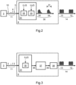
- Fig.2 illustrates an idea of forming pulse bursts with a regenerative amplifier.
- the module 4 comprises a regenerative amplifier 31 with one or two optical switches 32, 33 in the resonator, which together act as a valve to inject a pulse from the oscillator and to maintain resonator closed (high resonator quality) for the intended number of resonator roundtrips for regenerative amplification.
- Said optical switches 32, 33 also execute a resonator dumping during a time interval ⁇ t which is longer than the resonator roundtrip time.
- the resonator is partially transmissive - only a part of the energy of the pulse circulating in the resonator is ejected during one roundtrip, and thus bursts 34, 35 of pulses are formed (sequence 36). Finally, the optical switches 32, 33 open the resonator completely (low resonator quality).
- the optical switches 32, 33 are electro-optical switches (Pockels cells), driven by voltage signals U 1 ( t ) and U 2 ( t ), respectively, control the quality of the resonator and the dumping level through a polarizer placed in the resonator.
- the initial state of the resonator is when the resonator is completely closed (no voltage on the electro-optical switches is applied). Neither generation nor amplification occurs due to high losses caused by the quarter-wave plate.
- a voltage is applied to the electro-optical switches to compensate for the effect of the waveplates and to minimize losses. The amplification of the pulse trapped in the resonator begins.
- the pulse passes many times through an active medium and is amplified from 10 2 to 10 4 times during the closed resonator stage. After some number of resonator roundtrips, voltage on the electro-optical switches is reduced for the time interval ⁇ t . In this way, a part of the amplified pulse is ejected from the resonator and the rest is further amplified. The moment at which the resonator is partially opened, is selected depending on a desired temporal profile of the pulse bursts 34, 35.
- the pulse repetition rate f 2 of the pulses ejected from the resonator is inversely proportional to the resonator roundtrip time. After the time interval ⁇ t , the resonator is fully opened in order to completely dump it.
- the regenerative amplifier 31 operating in this mode performs both amplification and burst forming functions. And this is one of the distinctive features of the present invention.
- the aim is to form such a temporal profile of the bursts 34, 35 that pump pulse bursts 12, 13 at the output of the whole module 4 have amplitude variation of the most intense pulses not exceeding 20%.
- the module 4 may have additional amplification stages.
- the small resonator length of the regenerative amplifier results in a short roundtrip time, which determines the pulse repetition rate f 2 inside the bursts 34, 35.
- a resonator of about 30 cm is required to obtain 500 MHz, and a resonator of about 15 cm for 1 GHz. It is not easy to form a very short resonator with two electro-optical switches, so it is better to use one electro-optical switch (see a preferable realization below, in Fig.3 and Fig.4 ).
- Fig.3 shows a structure of the pulse bursts formation and amplification module 4 in the preferable embodiment of the present invention.
- the module 4 includes a short-resonator solid-state regenerative amplifier 31, a solid-state linear amplifier 37 and a harmonics generation device 38.
- the regenerative amplifier 31 contains only one electro-optical switch 32 driven by a multi-level voltage signal U 3 (t).
- the wavelength of the pump radiation must be in the visible region of the spectrum. Therefore, the second, third or fourth harmonic radiation is generated from the fundamental radiation of the amplifiers. It is possible to generate pump radiation in the spectral region between 250 nm and 750 nm.
- OPO with a BBO nonlinear crystal pumped by 355 nm radiation has an extremely wide continuous tuning range from 395 nm to 2600 nm.
- the tuning range of BBO pumped at 532 nm is narrower, from 670 nm to 2600 nm, since absorption of the crystal increases from 2600 nm.
- the BIBO nonlinear crystal has a narrower tuning range than the BBO, but the nonlinear gain is higher, and the spectral line of the parametrically amplified radiation is narrower than that from the BBO.
- KTA and KTP crystals pumped with 532 nm radiation can cover the range from 610 nm to 4000 nm.
- Lithium niobate crystals are transparent up to 5000 nm.
- the highest repetition rate f 3 at which the regenerative amplifier can operate stably and with repeatable characteristics depends on the energy of the seed pulse and the lifetime of the excited state of the active medium.
- a regenerative amplifier with the Nd:YVO 4 active medium providing a few tens of nJ of pulse energy, operates stably up to 10 kHz pulse repetition rate f 3 .
- the Nd:YAG medium has a longer lifetime of the excited state, thus the amplifier would operate stably up to 5 kHz.
- Up to f 3 5 kHz, any of Nd:YAG and Nd:YVO 4 or other Nd-ion doped active media can be used in the LD-pumped regenerative amplifier of this invention laser source.
- the upper limit of the repetition rate of the pulse bursts can be extended to 20 kHz. There is no limit into the low rates side, but repetition rates of at least 500 Hz are preferable for contemporary spectroscopic applications.
- pulse bursts are formed by the regenerative amplifier and then amplified in the linear amplifier, it is important to take into account a saturation of the amplifier. This means that the beginning of the pulse burst envelope must be of a rising shape. Therefore, the rising-envelope bursts 34, 35 (shown in Fig.2 ) from the regenerative amplifier 31 are suitable for providing flat-top bursts at the output of the amplifier 37 (sequence 39). High peak power pulses from the amplifier 37 are then efficiently converted to harmonic radiation in the device 38. Amplitudes of the pulses in the bursts 12, 13 differ by no more than 20% after the generation of harmonics.
- the total amplification factor of the regenerative amplifier 31 and the linear amplifier 37 must be at least 10 4 , as well as the efficiency of the harmonic generator 38 must be at least 25% to meet the requirement that the peak power of 5 to 15 pump pulses is 800 kW or higher and sum energy of the pump pulse bursts 12, 13 attains hundreds of microjoules.
- the moment of turning on a partial transmission of the resonator of the regenerative amplifier 31 is when the energy of the pulse circulating inside the resonator achieves 1 ⁇ J.
- Nd:YVO 4 active media were used in both the regenerative and linear amplifiers 31, 37, and BBO and LBO second and third harmonic crystals were used in the harmonics generation device 38.
- f 3 10 kHz
- 330 ⁇ J sum energy of bursts at 355 nm was obtained.
- a bandwidth of the pump pulses 15-17 and 18-20 did not exceed 1.4 cm -1 , and a duration was 40 ps.
- Fig.4 shows an optical layout of one of the possible embodiments of a compact regenerative amplifier suitable for fulfilling the pulse bursts formation and amplification module 4 according to Fig.3 .
- Mirrors 40, 41 and polarizers 42, 43 form a resonator 44 of the regenerative amplifier 31 with an optical length L 1 .
- the mirror 40 is high-reflective for the amplified radiation
- the mirror 41 is dichroic - transmissive for the pump radiation 45 and high-reflective for the amplified radiation.
- the resonator 44 contains an active element 46, a Pockels cell 32, and a quarter-wave plate 47. With no voltage applied to the Pockels cell 32, a double pass through the quarter-wave plate 47 changes radiation polarization to orthogonal.
- a pulse picker 48 reduces the pulse repetition rate of the seed pulse train 11 - selects only those pulses which are intended to be amplified. It transmits pulses from the train 11 which repeat at a rate f 3 and reflects other pulses to the side.
- the picked pulse 5 (selected for the amplification) passes an optical isolator 49 consisting of a Faraday rotator, a half-wave plate and a polarizer or a pair of polarizers.
- the isolator 49 protects the source of seed pulses from back-returning reflected radiation or spontaneous emission of the amplifier active element.
- Seed pulse of p polarization enters the resonator 44 of the regenerative amplifier 31 through the polarizer 42.
- polarization of radiation - which passes the quarter-wave plate 47, is reflected by the mirror 40 and passes the quarter-wave plate 47 for the second time - is rotated by 90 degrees.
- the pulse of s polarization is now reflected by the polarizer 42.
- Trapping of the seed pulse in the regenerative amplifier occurs by applying a quarter-wave voltage U ⁇ /4 between electrodes of the Pockels cell 32. If a quarter-wave phase delay is established ( U ⁇ /4 voltage grows up) before the pulse passes through the Pockels cell 32 for the second time, the quarter-wave plate 47 and the Pockels cell 32 act together as a half-wave plate. Pulses making a double pass would not experience any polarization change, thus after reflection from the polarizer 42 would stay the resonator. The moment of tuning on the voltage on the Pockels cell is chosen in such a way that to ensure the most stable operation of the amplifier, even if only a part of the seed pulse is injected into the resonator.
- the accuracy of the voltage switching moment ensures energy stability of the output pulses by at least 1%.
- the pulse After the pulse is amplified up to a desired level, part of its energy is outcoupled from the resonator 44 in the following way: a double pass through the quarter-wave plate 47 and the Pockels cell 32 to which a lower than U ⁇ /4 voltage is applied changes polarization of radiation. It is partially transmitted by the polarizer 42.
- the optical isolator 49 directs it to a direction other than the initial direction of the seed pulse.
- a mirror 50 further directs it to the output port of the amplifier 31. If the voltage were turned off completely, the phase of partial transmittance of the resonator would last only as long as a trailing edge of the voltage signal lasts.
- the phase of partial transmittance of the resonator lasts longer.
- the pulse circulating inside the resonator 44 makes many roundtrips, and a part of its energy is outcoupled from the resonator on each roundtrip.
- This forms a burst 34 of pulses of a desired duration and energy, and consisting of 5 to 15 pulses (counting at half-maximum-amplitude level of the burst).
- the voltage on the Pockels cell drops to 0V, all energy of the pulse is ejected from the resonator. It is best to completely open the resonator when the required duration and energy burst is formed.
- Pumping and accumulation of inversion in the active element 46 for the new amplification cycle can be started immediately after emptying the resonator.
- the first high-voltage source 52 supplies a positive potential, and a key 53, which is controlled by a synchronization pulse S 1 , generates a voltage pulse U 1 ( t ) applied to the first electrode of the Pockels cell.
- the second high-voltage source 54 supplies a negative potential, and a key 55, which is controlled by a synchronization pulse S 2 , generates a pulse U 2 ( t ) , applied to the second electrode of the Pockels cell.
- both keys 53, 55 begin to open.
- the first key 53 begins to close.
- the second key 55 begins to close.
- the Pockels cell 32 is still exposed to the potential difference, so the resonator is still partially transmissive.
- the moments t 1 and t 2 of switching the high voltage off are selected so that the total time when the resonator has partial transmittance is about 10 ns.
- Figs.6A-6D are modelling results of how the shape and energy of the pulse burst 34 at the output of the regenerative amplifier 31 is controlled by varying the moments of switching on and switching off the resonator partial transmittance and by changing the potential difference on the electrodes of the Pockels cell.
- a time scale corresponds to a number of roundtrips N .
- the resonator dumping level is shown as the coefficient R ( N ) of reflection back to the resonator.
- U 3 '( N ), U 3 "( N ), U 3 *( N ), U 3 **( N ) are Pockels cell driving voltage functions, where time is expressed as the number of resonator roundtrips N.
- Fig.6A and Fig.6B illustrate how the shape of the regenerative amplifier pulse burst depends on the beginning time of the resonator partial transmission.
- a longer burst 59" of pulses with increasing amplitudes can be formed ( Fig.6B ).
- a short flat-top pulse burst 59' can be formed ( Fig.6A ).
- Fig.6C and Fig.6D illustrate how the shape of the regenerative amplifier pulse burst depends on the partial transmission level 60 and 61 when N t1 and N t2 are fixed.
- Figs.7A-7C depict various possible embodiments of the synchronously pumped OPO 2.
- Mirrors 62 and 63 form a linear resonator 64 of an optical length L 2 .
- the mirrors are flat or concave.
- the OPO of Fig.7A and Fig.7B comprises a pair of collinearly pumped nonlinear crystals 65, 66, a pump radiation input separator 67 and several additional elements placed in the resonator along its optical axis.
- Separator 67 reflects the pump radiation, e. g. 355 nm, and completely transmits the parametrically generated radiation.
- a telescope 68 focuses the pump radiation into the nonlinear crystals.
- Element 70 is a spectral filter, if necessary.
- the wavelength tuning of the OPO is performed by varying an angle between the optical axis of the crystal and the pump radiation direction (and thus the resonator axis). Physically, this is done by rotating the nonlinear crystals 65, 66 (angular tuning). Using the pair of nonlinear crystals, the parallel beam shift is compensated, and, by symmetrically aligning, the aperture effect is compensated. A symmetric beam of parametrically generated radiation is obtained. Temperature tuning is also applicable, but in this case, it is not possible to realize a fast change of wavelengths.
- the optical length L 2 of the resonator 64 must be equal to the optical length L 1 of the resonator 44 of the regenerative amplifier. This condition can be satisfied by adjusting both the length of the OPO resonator 64 and the length of the regenerative amplifier resonator 44.
- the length adjustment of the resonator 64 is implemented by using compensators 71 and 72 (parallel transparent plates), which are rotated.
- the rotation of the compensators 71 and 72 is synchronized with the rotation of the nonlinear crystals 65, 66. Rotation changes optical thicknesses of the plates and this compensates for changes in the optical thicknesses of nonlinear crystals when the wavelength of the generated radiation is tuned. Holders of the resonator end mirrors 62, 63 are fixed.
- Fig.7B is a variant of the length adjustment of the resonator 64 realized by moving one of the end mirrors: a holder of the mirror 62 is mounted on a positioning table, the change of position of which is synchronized with the rotation of the nonlinear crystals 65, 66.
- spectral narrowing e. g. an etalon 73 or a diffraction grating instead of the mirror 62.
- phase-matching is ensured for a relatively narrow spectral range of the signal and idler waves, thus the spectral narrowing element can be omitted.
- the bandwidth of the parametrically generated radiation is typically larger than the bandwidth of the pump radiation.
- the bandwidth of the output radiation also depends on the signal and idler wavelengths ⁇ S and ⁇ I .
- the bandwidth of the pump radiation at 355 nm is less than 1.4 cm -1
- the bandwidth of the parametric radiation 24 generated in the BBO crystals will not exceed 10 cm -1 over the entire tuning range in a flat-mirror resonator 62, 63; and will not exceed 8 cm -1 if using the diffraction grating.
- the resonance condition is satisfied for the signal wave: the length of the resonator 64 is equal to an integer number of signal wavelengths ⁇ S , and the mirror 63 is highly-transmissive for the idler wave and partially transmissive for the signal wave.
- An optimal reflection coefficient of the mirror 63 for the signal wavelengths in the (395-709) nm range is 50%.
- the reflection coefficient up to 75% may also be used for the mirror 63, which will return a larger portion of the signal wave energy to the resonator, thereby accelerating the build up of parametric radiation in the resonator 64. Since the resonator 64 is short, the beam spot of radiation is small and the beam diverges rapidly.
- a collimating lens 74 is present near the output of the OPO (in front of or behind the filter 70).
- the polarization selective element 75 shown in Fig.7A, Fig.7B preferably is a Rochon prism. Depending on the orientation of the Rochon prism 75, either signal or idler wave radiation is transmitted to the output port. The other portion of the radiation 76 is directed to a beam dump, or to an additional output port.
- Fig.7C shows an embodiment of non-collinear phase-matching OPO 2.
- the signal or idler wave propagate along a cutting axis of the nonlinear crystal.
- Non-collinear interactions can be realized using a single nonlinear crystal 77 without rotating it, and the resonator can be extremely compact.
- the pump radiation is directed at an angle to the nonlinear crystal 77 (the unabsorbed part, after one pass, is absorbed in the beam dump 79).
- the gain bandwidth is extremely wide, so spectral filters and/or etalons 80 are necessary for the wavelength tuning and narrowing of the spectrum.
- Ring resonator OPO configurations consisting of three or four mirrors can also be made. However, they become impractical for constructing OPO of a short resonator.
- Fig.8 shows another embodiment of the present invention.
- the pulse bursts formation and amplification module consists of the regenerative amplifier 31 and the linear power amplifier 37, but there the harmonics generation device is absent.
- pump radiation 14 is the fundamental radiation of the active medium of amplifiers.
- the wavelength-tunable radiation with a variable repetition rate of bursts may be needed. Therefore, the pump laser may provide picosecond-pulse bursts at a variable repetition rate, and pulse bursts of wavelength-tunable radiation are generated only when the pump pulse bursts arrive to the optical parametric oscillator.
- the variable burst repetition rate of the pump laser can be accomplished in several ways. First, the laser oscillator for seeding the pump laser is selected from oscillators that have an ability to emit pulses on demand. Second, there is an additional optical switch at the output of the pump laser, which selects only required bursts from the generated sequence of bursts.
- amplitude of oscillator pulses is modulated so that their gain and evolution in the bursts formation and amplification module is different. Due to the reduced peak power of the pump pulses, the parametric generation will only occur from the high-energy pump pulse bursts.
- the OPO of the present invention pumped with ns-long bursts of picosecond pulses results in high efficiency: the exact temporal coincidence of the pump pulse and the generated parametric pulse on every roundtrip leads to conversion efficiency of at least 10%.
- the regular temporal structure of the pump pulse bursts as compared to the noisy structure of the multimode nanosecond pulse, is the main reason of high nonlinear conversion efficiency.
- the duration of the peaks present in the nanosecond pulse is of the same order as the duration of the picosecond pump pulses of this invention.
- nanosecond OPOs, with the same pump pulse energy are several times less efficient than the OPO of the present invention.
- the bandwidth of the wavelength-tunable radiation generated in the OPO, which is pumped with several-ns-long burst of picosecond pulses, is identical to that of the ns-pulse pumped OPO.
- the duration of the generated parametric output pulse burst is identical to the pulse duration obtained by the ns-pulse pumped OPO.
- the proposed wavelength-tunable laser source has a capability to cover a very wide spectral range from UV to NIR, from ⁇ 400 nm to -5000 nm. If sum or difference frequency generation with the residual pump radiation is additionally realized, the tuning range extends to the UV range down to 190 nm and to the mid-IR range up to 16 ⁇ m. Periodically poled nonlinear crystals can also be used; temperature tuning is then preferable.
- the described wavelength-tunable source of pulsed laser radiation of the present invention is compact, easily serviceable and reliable. Due to the short resonator, which corresponds to a pulse repetition rate from 200 MHz to 2 GHz, all the configurations of the optical parametric oscillator described above are very compact and therefore weakly respond to external factors. Requirements for the resonator length stabilization feedback system, which adjusts the optical lengths of the regenerative amplifier and the OPO resonators, are easy to implement. The synchronous pumping in a time interval of several nanoseconds allows to achieve a greater than 10% efficiency of parametric light generation in bulk nonlinear crystals in the entire tuning range. The energy of individual parametrically generated pulses is of the order of microjoules.
- the tuning range from 200 nm to 5000 nm can be covered by selecting a proper pumping wavelength and nonlinear crystal material. After additional sum or difference frequency generation, the tuning range covers from 200 nm to 16 ⁇ m.
- the radiation of ns-long picosecond pulse bursts with a spectral width not exceeding 3 cm -1 and high burst repetition rate is highly suitable for spectroscopic applications.
Landscapes
- Physics & Mathematics (AREA)
- Nonlinear Science (AREA)
- Optics & Photonics (AREA)
- Electromagnetism (AREA)
- General Physics & Mathematics (AREA)
- Engineering & Computer Science (AREA)
- Plasma & Fusion (AREA)
- Spectroscopy & Molecular Physics (AREA)
- Chemical & Material Sciences (AREA)
- Crystallography & Structural Chemistry (AREA)
- Optical Modulation, Optical Deflection, Nonlinear Optics, Optical Demodulation, Optical Logic Elements (AREA)
- Lasers (AREA)
Claims (15)
- Wellenlängenabstimmbare Quelle gepulster Laserstrahlung für VIS-NIR-Spektroskopie, die eine Pumppulsquelle (1) und einen optisch-parametrischen Oszillator (2) umfasst, wobeidie Pumppulsquelle (1) umfasst:∘ einen Laseroszillator (3), der eine kontinuierliche Folge (11) von Pikosekunden-Seed-Pulsen (5-10) erzeugt, die durch eine erste Wiederholungsrate f 1 im Bereich von 10 kHz bis 100 MHz definiert sind;∘ ein Modul (4) zur Bildung und Verstärkung von Pulsbursts, das eine Folge (14) von Bursts (12, 13) von Pumppulsen bereitstellt, wobei jeder Burst (12, 13) von Pumppulsen aus Pikosekunden-Pumppulsen (15-17), (18-20) besteht, die sich mit einer zweiten Wiederholungsrate f 2 wiederholen, die höher als die erste Wiederholungsrate f 1 ist und im Bereich von 200 MHz bis 2 GHz liegt; wobei ein Zeitintervall zwischen benachbarten Bursts (12, 13) von Pumppulsen einer dritten Wiederholungsrate f 3 entspricht, die niedriger als die zweite Wiederholungsrate f 2 und niedriger als die oder gleich der ersten Wiederholungsrate f 1 ist;der optisch-parametrische Oszillator (2) umfasst:∘ mindestens einen nichtlinearen optisch-parametrischen Verstärkungskristall, der in einem optischen Resonator (64) angeordnet ist, wobei aus einem Strahlungsphoton der Pumpwellenlänge λP zwei Photonen niedrigerer Energie erzeugt werden: ein Signalwellenphoton der Wellenlänge λS und ein Idlerwellenphoton der Wellenlänge λI;∘ mindestens zwei Spiegel (62, 63), die den optischen Resonator (64) mit einer Länge L 2 bilden;wobei die Pumppulsquelle (1) und der optisch-parametrische Oszillator (2) so aneinander angepasst sind, dass eine Umlaufzeit des Resonators (64) des optisch-parametrischen Oszillators (2) gleich einem Zeitintervall 1/f 2 zwischen benachbarten Pumppulsen (15, 16) ist;wobei der optisch-parametrische Oszillator (2) eine Folge (24) von Bursts (22, 23) von Ausgangspulsen bereitstellt, wobei jeder Burst (22, 23) von Ausgangspulsen aus Pikosekundenpulsen (25-27), (28-30) einer Signal- und/oder Idlerwelle besteht,dadurch gekennzeichnet, dass• das Modul (4) zur Bildung und Verstärkung von Pulsbursts einen festkörper regenerativen Verstärker (31) mit einem oder zwei optischen Schaltern (32, 33) in seinem Resonator (44) umfasst; wobei∘ die optischen Schalter (32, 33) so konfiguriert sind, dass durch Anlegen einer Spannung an beide oder einen der optischen Schalter (32, 33) Seedpulse (5, 10), die um ein Zeitintervall 1/f 3 voneinander beabstandet sind, in dem Resonator (44) gefangen werden; wobei die Genauigkeit eines Zeitpunkts t 0 beim Einschalten der Spannung eine Energiestabilität der Ausgangspulse von mindestens 1% gewährleistet;∘ durch Abschalten der Spannung an einem der optischen Schalter (32, 33) oder Reduzieren der Spannung an beiden oder einem der optischen Schalter (32, 33) zu einem Zeitpunkt t 1 eine teilweise Durchlässigkeit des Resonators (44) für ein Zeitintervall Δt erzeugt wird, das länger als eine Umlaufzeit des Resonators (44) ist, und ein Teil der Energie eines in dem Resonator zirkulierenden Pulses ausgekoppelt wird;∘ die Dauer der Bursts (12, 13) von Pumppulsen gleich dem Zeitintervall Δt ist;• die dritte Wiederholungsrate f 3 im Bereich von 500 Hz bis 10 kHz liegt;• jeder Burst (12, 13) von Pumppulsen 7 bis 15 aufeinanderfolgende Pumppulse mit einer Spitzenleistung von über 800 kW enthält, während die Summenenergie jedes Bursts (12, 13) von Pumppulsen nicht weniger als 300 µJ beträgt;• eine Bandbreite der Pumppulse (15-17), (18-20) 1 cm-1 nicht überschreitet, während eine Dauer von 15 ps bis 70 ps ist;• für die Pumpwellenlänge λP eine Phasenanpassungsbedingung für eine optisch-parametrische Verstärkung in dem nichtlinearen Kristall über den gesamten Transparenzbereich des nichtlinearen Kristalls erfüllt ist;• die Umwandlungseffizienz von der Folge (14) der Bursts von Pumppulsen in die Folge (24) der Bursts von Ausgangspulsen in einem gesamten Wellenlängenabstimmungsbereich mindestens 10% beträgt;• jeder Burst (22, 23) von Ausgangspulsen 5 bis 10 aufeinanderfolgende Ausgangspulse mit einer Spitzenleistung von über 10 kW in dem gesamten Wellenlängenabstimmbereich aufweist;• eine Bandbreite der Ausgangsstrahlung (24) 10 cm-1 nicht überschreitet;• beim Pumpen mit Nahinfrarot-Laserstrahlung oder deren Harmonischen der Wellenlängenabstimmungsbereich der Ausgangsstrahlung (24) über den sichtbaren und den Nahinfrarot-Spektralbereich abdeckt.
- Quelle nach Anspruch 1, dadurch gekennzeichnet, dass
der Resonator (44) des regenerativen Verstärkers (31) einen elektrooptischen Schalter (32) aufweist, der durch ein Zweipegel-Spannungssignal U 3 (t) gesteuert wird. - Quelle nach Anspruch 1 oder 2, dadurch gekennzeichnet, dass
der Zeitpunkt t 1, zu dem eine teilweise Durchlässigkeit des Resonators des regenerativen Verstärkers (31) erzeugt wird, der Zeitpunkt ist, zu dem die Energie des in dem Resonator zirkulierenden Pulses den Wert von 1 µJ erreicht. - Quelle nach einem der vorhergehenden Ansprüche, dadurch gekennzeichnet, dass
das Modul (4) zur Bildung und Verstärkung von Pulsbursts einen festkörper linearen Verstärker (37) auch umfasst; wobei eine Gesamtverstärkung des regenerativen Verstärkers (31) und des linearen Verstärkers (37) nicht weniger als 104 beträgt. - Quelle nach Anspruch 4, dadurch gekennzeichnet, dass• der Laseroszillator (3) ein modengekoppelter Nd:YVO4- oder Nd:YAG-Festkörper-Oszillator ist, der Pikosekundenpulse mit einer Energie von (1-10) nJ bei einer Wiederholungsrate f 1 von 80 MHz erzeugt;• der regenerative Verstärker (31) ein regenerativer Verstärker aus Nd:YVO4- oder Nd:YAG-Medium ist, der Pulsbursts (34, 35) mit einer Energie von über 20 µJ bildet, wenn die Wiederholungsrate f 3 der Bursts 10 kHz beträgt;• der lineare Verstärker (37) ein Single-Pass- oder Double-Pass-Verstärker aus Nd:YVO4- oder Nd:YAG-Medium ist, an dessen Ausgang die Energie von Pulsbursts 1 mJ bei f 3 gleich 10 kHz übersteigt.
- Quelle nach einem der vorhergehenden Ansprüche, dadurch gekennzeichnet, dass
ein Paar der während der parametrischen Wechselwirkung erzeugten Wellenlängen λ S, λ I geändert wird durch: 1) Drehen des mindestens einen nichtlinearen optisch-parametrischen Verstärkungskristalls in Bezug auf seine optische Achse, 2) Ändern einer Temperatur des nichtlinearen Kristalls oder 3) Ändern einer Transmissions- oder Reflexions-Wellenlänge eines spektral selektiven Elements. - Quelle nach einem der vorhergehenden Ansprüche, dadurch gekennzeichnet, dass• sich der Pumpstrahlungsstrahl kollinear zur Achse des Resonators (64) des optisch-parametrischen Oszillators (2) ausbreitet;• der mindestens eine nichtlineare optisch-parametrische Verstärkungskristall ein Kristallpaar (65, 66) ist, ausgewählt aus BBO, BIBO, LBO, KTA, KTP, MgO:LiNbO3, ZnO:LiNbO3 oder anderen nichtlinearen Kristallen, die im VIS-NIR-Bereich transparent sind;• die Wellenlängenabstimmung durch symmetrisches Drehen beider Kristalle des Kristallpaars (65, 66) in entgegengesetzte Richtungen in Bezug auf die optischen Achsen der Kristalle und/oder durch Ändern der Temperatur der Kristalle (65, 66) durchgeführt wird.
- Quelle nach einem der vorhergehenden Ansprüche, dadurch gekennzeichnet, dass
die Wellenlänge der Pumpstrahlung im Bereich von 250 nm bis 1340 nm liegt. - Quelle nach einem der vorhergehenden Ansprüche, dadurch gekennzeichnet, dass
der Wellenlängenabstimmungsbereich der Ausgangsstrahlung (24) von 395 nm bis 2600 nm ist. - Quelle nach einem der Ansprüche 1 bis 8, dadurch gekennzeichnet, dass der Wellenlängenabstimmungsbereich der Ausgangsstrahlung (24) von 1350 nm bis 5000 nm ist.
- Quelle nach einem der vorhergehenden Ansprüche, dadurch gekennzeichnet, dass
die Bandbreite der Ausgangsstrahlung (24) 3 cm-1 nicht überschreitet. - Quelle nach einem der vorhergehenden Ansprüche, dadurch gekennzeichnet, dasseine volle Breite auf Halbmaximum-Amplitude der Bursts (12, 13) von Pumppulsen im Bereich von 5 ns bis 10 ns liegt, unddie Amplitude der Pumppulse mit einer Spitzenleistung von über 800 kW um nicht mehr als 20% unterscheidet.
- Quelle nach einem der vorhergehenden Ansprüche, dadurch gekennzeichnet, dass
ein Spiegel (63) der mindestens zwei Spiegel, die den optischen Resonator (64) bilden, für die Wellenlänge λ S der Signalwelle teilweise durchlässig und für die Wellenlänge λ I der Idlerwelle hoch durchlässig ist. - Quelle nach einem der vorhergehenden Ansprüche, dadurch gekennzeichnet, dass
das Anpassen der Umlaufzeit des Resonators (64) des optisch-parametrischen Oszillators (2) an das Zeitintervall 1/f 2 zwischen benachbarten Pumppulsen (15, 16) durch Einstellen der Länge L2 des Resonators (64) oder der Länge L1 des Resonators (44) des regenerativen Verstärkers (31) durchgeführt wird. - Quelle nach einem der vorhergehenden Ansprüche, dadurch gekennzeichnet, dass
während einer Drehung des mindestens einen optisch-parametrischen nichtlinearen Kristalls relativ zu seiner optischen Achse oder seiner Temperaturänderung zur Wellenlängenabstimmung die Länge L 2 des optisch-parametrischen Oszillatorresonators (64) eingestellt wird; wobei die Längeneinstellung entsprechend dem höchsten Wert der Durchschnittsleistung der Ausgangsstrahlung (24) durchgeführt wird.
Applications Claiming Priority (2)
| Application Number | Priority Date | Filing Date | Title |
|---|---|---|---|
| LT2020559A LT6919B (lt) | 2020-12-02 | 2020-12-02 | Derinamo bangos ilgio impulsinės lazerinės spinduliuotės šaltinis vis-nir spektroskopijai |
| PCT/IB2021/060557 WO2022118120A1 (en) | 2020-12-02 | 2021-11-15 | Wavelength-tunable source of pulsed laser radiation for vis-nir spectroscopy |
Publications (3)
| Publication Number | Publication Date |
|---|---|
| EP4256659A1 EP4256659A1 (de) | 2023-10-11 |
| EP4256659C0 EP4256659C0 (de) | 2024-09-18 |
| EP4256659B1 true EP4256659B1 (de) | 2024-09-18 |
Family
ID=75108707
Family Applications (1)
| Application Number | Title | Priority Date | Filing Date |
|---|---|---|---|
| EP21810435.4A Active EP4256659B1 (de) | 2020-12-02 | 2021-11-15 | Wellenlängenabstimmbare quelle gepulster laserstrahlung für vis-nir-spektroskopie |
Country Status (4)
| Country | Link |
|---|---|
| US (1) | US12455492B2 (de) |
| EP (1) | EP4256659B1 (de) |
| LT (1) | LT6919B (de) |
| WO (1) | WO2022118120A1 (de) |
Families Citing this family (7)
| Publication number | Priority date | Publication date | Assignee | Title |
|---|---|---|---|---|
| DE112021006831T5 (de) * | 2021-01-18 | 2023-11-02 | Sony Semiconductor Solutions Corporation | Fotodetektionsvorrichtung und fotodetektionssystem |
| CN115377786B (zh) * | 2022-10-27 | 2023-02-14 | 武汉中科锐择光电科技有限公司 | 一种提高激光脉冲时域对比度的系统及方法 |
| US20240361457A1 (en) * | 2023-04-26 | 2024-10-31 | Aeva, Inc. | Techniques for rapid soa modulation |
| TWI907076B (zh) * | 2024-09-18 | 2025-12-01 | 亞勝開發有限公司 | 鎖模雷射檢測裝置及方法 |
| CN119864702B (zh) * | 2024-12-31 | 2025-11-14 | 武汉光至科技有限公司 | 一种陡峭边沿超快脉冲串激光控制装置及使用方法 |
| CN119726338B (zh) * | 2025-03-03 | 2025-05-06 | 西安电子科技大学 | 一种高功率多GHz重复频率的飞秒光参量振荡器 |
| CN121602215B (zh) * | 2026-01-28 | 2026-04-07 | 山东大学 | 基于泵浦脉冲时域调制的opo光束质量优化方法及系统 |
Family Cites Families (7)
| Publication number | Priority date | Publication date | Assignee | Title |
|---|---|---|---|---|
| US20080273559A1 (en) * | 2007-05-04 | 2008-11-06 | Ekspla Ltd. | Multiple Output Repetitively Pulsed Laser |
| GB0909295D0 (en) | 2009-05-29 | 2009-07-15 | Univ Heriot Watt | Optical apparatus |
| JP5933591B2 (ja) | 2010-12-30 | 2016-06-15 | ロッキード・マーチン・コーポレーション | 光学的にロックされた高エネルギーopo−opa |
| EP3018774A1 (de) | 2014-11-04 | 2016-05-11 | High Q Laser GmbH | Verfahren zur Erzeugung eines Burst-Modus mittels Schaltens einer Pockelszelle |
| GB2562236A (en) * | 2017-05-08 | 2018-11-14 | Uab Mgf Sviesos Konversija | Device and method for generation of high repetition rate laser pulse bursts |
| US10464453B2 (en) | 2017-09-19 | 2019-11-05 | Kiekert Ag | Motor vehicle seat, in particular a motor vehicle rear seat |
| US12438325B2 (en) | 2019-09-26 | 2025-10-07 | Uab ,,Ekspla″ | Method for generating gigahertz bursts of pulses and laser apparatus thereof |
-
2020
- 2020-12-02 LT LT2020559A patent/LT6919B/lt not_active IP Right Cessation
-
2021
- 2021-11-15 US US18/255,737 patent/US12455492B2/en active Active
- 2021-11-15 WO PCT/IB2021/060557 patent/WO2022118120A1/en not_active Ceased
- 2021-11-15 EP EP21810435.4A patent/EP4256659B1/de active Active
Also Published As
| Publication number | Publication date |
|---|---|
| LT6919B (lt) | 2022-06-27 |
| EP4256659C0 (de) | 2024-09-18 |
| US20240027873A1 (en) | 2024-01-25 |
| WO2022118120A1 (en) | 2022-06-09 |
| EP4256659A1 (de) | 2023-10-11 |
| LT2020559A (lt) | 2022-06-10 |
| US12455492B2 (en) | 2025-10-28 |
Similar Documents
| Publication | Publication Date | Title |
|---|---|---|
| EP4256659B1 (de) | Wellenlängenabstimmbare quelle gepulster laserstrahlung für vis-nir-spektroskopie | |
| US6580732B1 (en) | Multiple mode laser | |
| US10014652B2 (en) | Broadly tunable optical parametric oscillator | |
| CN100483871C (zh) | 具有稳定频率的辐射的生成 | |
| US20120263196A1 (en) | Ultrafast raman laser systems and methods of operation | |
| US20120044959A1 (en) | Terahertz source | |
| CN107863683B (zh) | 一种光学参量振荡器 | |
| US7907644B2 (en) | High-repetition laser system for generating ultra-short pulses according to the principle of cavity dumping | |
| EP2244339B1 (de) | Modengekoppelte Festkörperlaservorrichtung | |
| Sirotkin et al. | New lasers based on c-cut vanadat crystals | |
| Ebrahimzadeh et al. | Temperature‐tuned noncritically phase‐matched picosecond LiB3O5 optical parameter oscillator | |
| Mølster et al. | Precisely tunable narrowband mid-infrared mJ pulses from a backward wave optical parametric oscillator | |
| Liu et al. | All-solid-state subnanosecond tunable ultraviolet laser sources based on Ce 3+-activated fluoride crystals | |
| Basiev et al. | Solid-state Raman lasers | |
| US6928090B1 (en) | Device and process for mode-locking a laser | |
| Rahm et al. | Widely tunable narrow-linewidth nanosecond optical parametric generator with self-injection seeding | |
| Debuisschert et al. | Nanosecond optical parametric oscillators | |
| Tang et al. | Optical parametric processes and broadly tunable femtosecond sources | |
| Rustad et al. | High pulse energy and symmetrical far field from an optical parametric oscillator in the red spectral range | |
| Reekie et al. | Difference frequency generation with a synchronously mode-locked cw dye laser system | |
| Novák et al. | Parametric Mid-IR Source Pumped by a High Power Picosecond Thin-Disk Laser | |
| CN119297714A (zh) | 基于脉冲种子注入式太赫兹参量源生成装置 | |
| Roissé et al. | Walk-off and phase-compensated resonantly enhanced frequency-doubling of picosecond pulses using type II nonlinear crystal | |
| Henrich et al. | Concepts and technologies of advanced RGB sources | |
| Mildren et al. | All-solid-state parametric anti-Stokes Raman laser at 508 nm |
Legal Events
| Date | Code | Title | Description |
|---|---|---|---|
| STAA | Information on the status of an ep patent application or granted ep patent |
Free format text: STATUS: UNKNOWN |
|
| STAA | Information on the status of an ep patent application or granted ep patent |
Free format text: STATUS: THE INTERNATIONAL PUBLICATION HAS BEEN MADE |
|
| PUAI | Public reference made under article 153(3) epc to a published international application that has entered the european phase |
Free format text: ORIGINAL CODE: 0009012 |
|
| STAA | Information on the status of an ep patent application or granted ep patent |
Free format text: STATUS: REQUEST FOR EXAMINATION WAS MADE |
|
| 17P | Request for examination filed |
Effective date: 20230414 |
|
| AK | Designated contracting states |
Kind code of ref document: A1 Designated state(s): AL AT BE BG CH CY CZ DE DK EE ES FI FR GB GR HR HU IE IS IT LI LT LU LV MC MK MT NL NO PL PT RO RS SE SI SK SM TR |
|
| DAV | Request for validation of the european patent (deleted) | ||
| DAX | Request for extension of the european patent (deleted) | ||
| GRAP | Despatch of communication of intention to grant a patent |
Free format text: ORIGINAL CODE: EPIDOSNIGR1 |
|
| STAA | Information on the status of an ep patent application or granted ep patent |
Free format text: STATUS: GRANT OF PATENT IS INTENDED |
|
| INTG | Intention to grant announced |
Effective date: 20240612 |
|
| GRAS | Grant fee paid |
Free format text: ORIGINAL CODE: EPIDOSNIGR3 |
|
| GRAA | (expected) grant |
Free format text: ORIGINAL CODE: 0009210 |
|
| STAA | Information on the status of an ep patent application or granted ep patent |
Free format text: STATUS: THE PATENT HAS BEEN GRANTED |
|
| AK | Designated contracting states |
Kind code of ref document: B1 Designated state(s): AL AT BE BG CH CY CZ DE DK EE ES FI FR GB GR HR HU IE IS IT LI LT LU LV MC MK MT NL NO PL PT RO RS SE SI SK SM TR |
|
| REG | Reference to a national code |
Ref country code: GB Ref legal event code: FG4D |
|
| REG | Reference to a national code |
Ref country code: CH Ref legal event code: EP |
|
| REG | Reference to a national code |
Ref country code: IE Ref legal event code: FG4D |
|
| REG | Reference to a national code |
Ref country code: DE Ref legal event code: R096 Ref document number: 602021019070 Country of ref document: DE |
|
| U01 | Request for unitary effect filed |
Effective date: 20240918 |
|
| U07 | Unitary effect registered |
Designated state(s): AT BE BG DE DK EE FI FR IT LT LU LV MT NL PT RO SE SI Effective date: 20241010 |
|
| U20 | Renewal fee for the european patent with unitary effect paid |
Year of fee payment: 4 Effective date: 20241029 |
|
| PG25 | Lapsed in a contracting state [announced via postgrant information from national office to epo] |
Ref country code: NO Free format text: LAPSE BECAUSE OF FAILURE TO SUBMIT A TRANSLATION OF THE DESCRIPTION OR TO PAY THE FEE WITHIN THE PRESCRIBED TIME-LIMIT Effective date: 20241218 |
|
| PG25 | Lapsed in a contracting state [announced via postgrant information from national office to epo] |
Ref country code: GR Free format text: LAPSE BECAUSE OF FAILURE TO SUBMIT A TRANSLATION OF THE DESCRIPTION OR TO PAY THE FEE WITHIN THE PRESCRIBED TIME-LIMIT Effective date: 20241219 |
|
| PG25 | Lapsed in a contracting state [announced via postgrant information from national office to epo] |
Ref country code: HR Free format text: LAPSE BECAUSE OF FAILURE TO SUBMIT A TRANSLATION OF THE DESCRIPTION OR TO PAY THE FEE WITHIN THE PRESCRIBED TIME-LIMIT Effective date: 20240918 |
|
| PG25 | Lapsed in a contracting state [announced via postgrant information from national office to epo] |
Ref country code: RS Free format text: LAPSE BECAUSE OF FAILURE TO SUBMIT A TRANSLATION OF THE DESCRIPTION OR TO PAY THE FEE WITHIN THE PRESCRIBED TIME-LIMIT Effective date: 20241218 |
|
| PG25 | Lapsed in a contracting state [announced via postgrant information from national office to epo] |
Ref country code: RS Free format text: LAPSE BECAUSE OF FAILURE TO SUBMIT A TRANSLATION OF THE DESCRIPTION OR TO PAY THE FEE WITHIN THE PRESCRIBED TIME-LIMIT Effective date: 20241218 Ref country code: NO Free format text: LAPSE BECAUSE OF FAILURE TO SUBMIT A TRANSLATION OF THE DESCRIPTION OR TO PAY THE FEE WITHIN THE PRESCRIBED TIME-LIMIT Effective date: 20241218 Ref country code: HR Free format text: LAPSE BECAUSE OF FAILURE TO SUBMIT A TRANSLATION OF THE DESCRIPTION OR TO PAY THE FEE WITHIN THE PRESCRIBED TIME-LIMIT Effective date: 20240918 Ref country code: GR Free format text: LAPSE BECAUSE OF FAILURE TO SUBMIT A TRANSLATION OF THE DESCRIPTION OR TO PAY THE FEE WITHIN THE PRESCRIBED TIME-LIMIT Effective date: 20241219 |
|
| PG25 | Lapsed in a contracting state [announced via postgrant information from national office to epo] |
Ref country code: IS Free format text: LAPSE BECAUSE OF FAILURE TO SUBMIT A TRANSLATION OF THE DESCRIPTION OR TO PAY THE FEE WITHIN THE PRESCRIBED TIME-LIMIT Effective date: 20250118 |
|
| PG25 | Lapsed in a contracting state [announced via postgrant information from national office to epo] |
Ref country code: SM Free format text: LAPSE BECAUSE OF FAILURE TO SUBMIT A TRANSLATION OF THE DESCRIPTION OR TO PAY THE FEE WITHIN THE PRESCRIBED TIME-LIMIT Effective date: 20240918 |
|
| PG25 | Lapsed in a contracting state [announced via postgrant information from national office to epo] |
Ref country code: ES Free format text: LAPSE BECAUSE OF FAILURE TO SUBMIT A TRANSLATION OF THE DESCRIPTION OR TO PAY THE FEE WITHIN THE PRESCRIBED TIME-LIMIT Effective date: 20240918 |
|
| PG25 | Lapsed in a contracting state [announced via postgrant information from national office to epo] |
Ref country code: CZ Free format text: LAPSE BECAUSE OF FAILURE TO SUBMIT A TRANSLATION OF THE DESCRIPTION OR TO PAY THE FEE WITHIN THE PRESCRIBED TIME-LIMIT Effective date: 20240918 Ref country code: PL Free format text: LAPSE BECAUSE OF FAILURE TO SUBMIT A TRANSLATION OF THE DESCRIPTION OR TO PAY THE FEE WITHIN THE PRESCRIBED TIME-LIMIT Effective date: 20240918 |
|
| PG25 | Lapsed in a contracting state [announced via postgrant information from national office to epo] |
Ref country code: SK Free format text: LAPSE BECAUSE OF FAILURE TO SUBMIT A TRANSLATION OF THE DESCRIPTION OR TO PAY THE FEE WITHIN THE PRESCRIBED TIME-LIMIT Effective date: 20240918 |
|
| REG | Reference to a national code |
Ref country code: CH Ref legal event code: PL |
|
| PG25 | Lapsed in a contracting state [announced via postgrant information from national office to epo] |
Ref country code: MC Free format text: LAPSE BECAUSE OF FAILURE TO SUBMIT A TRANSLATION OF THE DESCRIPTION OR TO PAY THE FEE WITHIN THE PRESCRIBED TIME-LIMIT Effective date: 20240918 |
|
| REG | Reference to a national code |
Ref country code: CH Ref legal event code: PL |
|
| PG25 | Lapsed in a contracting state [announced via postgrant information from national office to epo] |
Ref country code: CH Free format text: LAPSE BECAUSE OF NON-PAYMENT OF DUE FEES Effective date: 20241130 |
|
| PLBE | No opposition filed within time limit |
Free format text: ORIGINAL CODE: 0009261 |
|
| STAA | Information on the status of an ep patent application or granted ep patent |
Free format text: STATUS: NO OPPOSITION FILED WITHIN TIME LIMIT |
|
| 26N | No opposition filed |
Effective date: 20250619 |
|
| PG25 | Lapsed in a contracting state [announced via postgrant information from national office to epo] |
Ref country code: IE Free format text: LAPSE BECAUSE OF NON-PAYMENT OF DUE FEES Effective date: 20241115 |
|
| U20 | Renewal fee for the european patent with unitary effect paid |
Year of fee payment: 5 Effective date: 20251104 |
|
| PGFP | Annual fee paid to national office [announced via postgrant information from national office to epo] |
Ref country code: GB Payment date: 20251104 Year of fee payment: 5 |
|
| PG25 | Lapsed in a contracting state [announced via postgrant information from national office to epo] |
Ref country code: HU Free format text: LAPSE BECAUSE OF FAILURE TO SUBMIT A TRANSLATION OF THE DESCRIPTION OR TO PAY THE FEE WITHIN THE PRESCRIBED TIME-LIMIT; INVALID AB INITIO Effective date: 20211115 |
|
| PG25 | Lapsed in a contracting state [announced via postgrant information from national office to epo] |
Ref country code: CY Free format text: LAPSE BECAUSE OF FAILURE TO SUBMIT A TRANSLATION OF THE DESCRIPTION OR TO PAY THE FEE WITHIN THE PRESCRIBED TIME-LIMIT; INVALID AB INITIO Effective date: 20211115 |