EP4255355B1 - Vorrichtung zum greifen eines prothesenelements wie etwa eines bechers und verfahren zur verwendung einer greifvorrichtung als versuchseinsatz - Google Patents
Vorrichtung zum greifen eines prothesenelements wie etwa eines bechers und verfahren zur verwendung einer greifvorrichtung als versuchseinsatz Download PDFInfo
- Publication number
- EP4255355B1 EP4255355B1 EP21840648.6A EP21840648A EP4255355B1 EP 4255355 B1 EP4255355 B1 EP 4255355B1 EP 21840648 A EP21840648 A EP 21840648A EP 4255355 B1 EP4255355 B1 EP 4255355B1
- Authority
- EP
- European Patent Office
- Prior art keywords
- prosthetic element
- mechanical interface
- gripping
- preformed
- cup
- Prior art date
- Legal status (The legal status is an assumption and is not a legal conclusion. Google has not performed a legal analysis and makes no representation as to the accuracy of the status listed.)
- Active
Links
Images


Classifications
-
- A—HUMAN NECESSITIES
- A61—MEDICAL OR VETERINARY SCIENCE; HYGIENE
- A61F—FILTERS IMPLANTABLE INTO BLOOD VESSELS; PROSTHESES; DEVICES PROVIDING PATENCY TO, OR PREVENTING COLLAPSING OF, TUBULAR STRUCTURES OF THE BODY, e.g. STENTS; ORTHOPAEDIC, NURSING OR CONTRACEPTIVE DEVICES; FOMENTATION; TREATMENT OR PROTECTION OF EYES OR EARS; BANDAGES, DRESSINGS OR ABSORBENT PADS; FIRST-AID KITS
- A61F2/00—Filters implantable into blood vessels; Prostheses, i.e. artificial substitutes or replacements for parts of the body; Appliances for connecting them with the body; Devices providing patency to, or preventing collapsing of, tubular structures of the body, e.g. stents
- A61F2/02—Prostheses implantable into the body
- A61F2/30—Joints
- A61F2/46—Special tools for implanting artificial joints
- A61F2/4603—Special tools for implanting artificial joints for insertion or extraction of endoprosthetic joints or of accessories thereof
- A61F2/4609—Special tools for implanting artificial joints for insertion or extraction of endoprosthetic joints or of accessories thereof of acetabular cups
-
- A—HUMAN NECESSITIES
- A61—MEDICAL OR VETERINARY SCIENCE; HYGIENE
- A61F—FILTERS IMPLANTABLE INTO BLOOD VESSELS; PROSTHESES; DEVICES PROVIDING PATENCY TO, OR PREVENTING COLLAPSING OF, TUBULAR STRUCTURES OF THE BODY, e.g. STENTS; ORTHOPAEDIC, NURSING OR CONTRACEPTIVE DEVICES; FOMENTATION; TREATMENT OR PROTECTION OF EYES OR EARS; BANDAGES, DRESSINGS OR ABSORBENT PADS; FIRST-AID KITS
- A61F2/00—Filters implantable into blood vessels; Prostheses, i.e. artificial substitutes or replacements for parts of the body; Appliances for connecting them with the body; Devices providing patency to, or preventing collapsing of, tubular structures of the body, e.g. stents
- A61F2/02—Prostheses implantable into the body
- A61F2/30—Joints
- A61F2/46—Special tools for implanting artificial joints
- A61F2/4684—Trial or dummy prostheses
-
- A—HUMAN NECESSITIES
- A61—MEDICAL OR VETERINARY SCIENCE; HYGIENE
- A61F—FILTERS IMPLANTABLE INTO BLOOD VESSELS; PROSTHESES; DEVICES PROVIDING PATENCY TO, OR PREVENTING COLLAPSING OF, TUBULAR STRUCTURES OF THE BODY, e.g. STENTS; ORTHOPAEDIC, NURSING OR CONTRACEPTIVE DEVICES; FOMENTATION; TREATMENT OR PROTECTION OF EYES OR EARS; BANDAGES, DRESSINGS OR ABSORBENT PADS; FIRST-AID KITS
- A61F2/00—Filters implantable into blood vessels; Prostheses, i.e. artificial substitutes or replacements for parts of the body; Appliances for connecting them with the body; Devices providing patency to, or preventing collapsing of, tubular structures of the body, e.g. stents
- A61F2/02—Prostheses implantable into the body
- A61F2/30—Joints
- A61F2002/30001—Additional features of subject-matter classified in A61F2/28, A61F2/30 and subgroups thereof
- A61F2002/30316—The prosthesis having different structural features at different locations within the same prosthesis; Connections between prosthetic parts; Special structural features of bone or joint prostheses not otherwise provided for
- A61F2002/30329—Connections or couplings between prosthetic parts, e.g. between modular parts; Connecting elements
- A61F2002/30476—Connections or couplings between prosthetic parts, e.g. between modular parts; Connecting elements locked by an additional locking mechanism
- A61F2002/30484—Mechanically expandable devices located on the first prosthetic part for locking into or onto the second prosthetic part
-
- A—HUMAN NECESSITIES
- A61—MEDICAL OR VETERINARY SCIENCE; HYGIENE
- A61F—FILTERS IMPLANTABLE INTO BLOOD VESSELS; PROSTHESES; DEVICES PROVIDING PATENCY TO, OR PREVENTING COLLAPSING OF, TUBULAR STRUCTURES OF THE BODY, e.g. STENTS; ORTHOPAEDIC, NURSING OR CONTRACEPTIVE DEVICES; FOMENTATION; TREATMENT OR PROTECTION OF EYES OR EARS; BANDAGES, DRESSINGS OR ABSORBENT PADS; FIRST-AID KITS
- A61F2/00—Filters implantable into blood vessels; Prostheses, i.e. artificial substitutes or replacements for parts of the body; Appliances for connecting them with the body; Devices providing patency to, or preventing collapsing of, tubular structures of the body, e.g. stents
- A61F2/02—Prostheses implantable into the body
- A61F2/30—Joints
- A61F2/46—Special tools for implanting artificial joints
- A61F2/4603—Special tools for implanting artificial joints for insertion or extraction of endoprosthetic joints or of accessories thereof
- A61F2002/4625—Special tools for implanting artificial joints for insertion or extraction of endoprosthetic joints or of accessories thereof with relative movement between parts of the instrument during use
- A61F2002/4628—Special tools for implanting artificial joints for insertion or extraction of endoprosthetic joints or of accessories thereof with relative movement between parts of the instrument during use with linear motion along or rotating motion about an axis transverse to the instrument axis or to the implantation direction, e.g. clamping
-
- A—HUMAN NECESSITIES
- A61—MEDICAL OR VETERINARY SCIENCE; HYGIENE
- A61F—FILTERS IMPLANTABLE INTO BLOOD VESSELS; PROSTHESES; DEVICES PROVIDING PATENCY TO, OR PREVENTING COLLAPSING OF, TUBULAR STRUCTURES OF THE BODY, e.g. STENTS; ORTHOPAEDIC, NURSING OR CONTRACEPTIVE DEVICES; FOMENTATION; TREATMENT OR PROTECTION OF EYES OR EARS; BANDAGES, DRESSINGS OR ABSORBENT PADS; FIRST-AID KITS
- A61F2/00—Filters implantable into blood vessels; Prostheses, i.e. artificial substitutes or replacements for parts of the body; Appliances for connecting them with the body; Devices providing patency to, or preventing collapsing of, tubular structures of the body, e.g. stents
- A61F2/02—Prostheses implantable into the body
- A61F2/30—Joints
- A61F2/46—Special tools for implanting artificial joints
- A61F2002/4681—Special tools for implanting artificial joints by applying mechanical shocks, e.g. by hammering
Definitions
- the present invention relates to a device for gripping prosthetic elements such as cups and in particular to adaptations making it possible to ensure this gripping in the best conditions and to adapt this gripping in order to simplify the intraoperative testing phases.
- the closest prior art is the document WO 2018/109371 A1 , which defines the preamble of claim 1.
- Acetabular prostheses are well known in the orthopedic field. They are composed of a metal cup with a more or less hemispherical external shape, sometimes extended by a truncated or entire cylinder.
- the cup has an external surface which may or may not extend beyond the equator, a continuous or partially conical hemispherical concave internal surface, with or without a threaded pole hole for connecting an instrument.
- This cup can be a dual mobility cup with a smooth, polished, hemispherical internal surface, or a single mobility cup whose internal surface includes a wedging cone with a specific roughness, extended by more or less spherical caps.
- the interior of the cup can be of variable shape: hemispherical, hemispherical extended by a cylinder, partially conical.
- This cup is intended to be implanted in the bony cotyte of a patient.
- An insert is then assembled inside the cup forming the joint in which a femoral prosthetic head is placed.
- the interior surface conditions can vary: for a metal/polyethylene friction pair, it is polished, for a pair with a ceramic insert, the conical surface has a roughness suitable for assembly.
- the device comprises a gripper which is a separate subassembly from the handle.
- This gripper comprises teeth capable of engaging with the rims of the acetabular cup.
- the gripper comprises a movable pusher, capable, during its movement, of exerting a thrust on the acetabular cup along the axis of revolution of said acetabular cup, so as to disengage the rims of the acetabular cup from their engagement with the teeth included by the gripper.
- the gripping device comprises an actuating device for actuating the movable pusher,
- Such a device is intended for gripping sterile or non-sterile implants, prosthetic components, acetabular, glenoid, trial pieces, trial cups, trial inserts.
- a mechanical interface inserted into the interior volume of a prosthetic element such as a cup is particularly advantageous in that it increases, by fitting said interior volume, the adhesion surface for gripping purposes without making the resulting assembly more voluminous.
- the radiating lamella configuration provides the necessary elasticity to the interface to allow it to be held in position in the prosthetic element.
- the radiating lamella configuration provides the necessary elasticity to the interface to allow it to be held in position in the prosthetic element.
- the configuration of the radiating lamellae integrates the stress sectors that transmit the force on several congruent contact surfaces in the internal equatorial zone of the prosthetic element.
- the cutting into angular portions promotes and allows the functional clearances necessary for the realization by molding of the mechanical interface.
- the number of lamellae contributes to containing the volumes of the elements of the expansion axis.
- the convex outer surface formed by the outer surface of said lamellae is preformed with a peripheral groove formed between a convex surface portion positioned at the bottom of the inner volume of the prosthetic element and a convex surface portion positioned at the edge of the prosthetic element.
- This groove constitutes a separation in the outer profile of the lamellae contributing to their elasticity
- the internal surface of the profile of said slats is preformed with said peripheral support surfaces.
- said gripping module comprises a head of the gripping module which guides the translation of the expansion shaft, said head being split by a slot. This head is split by a slot so as to facilitate assembly and disassembly with the expansion shaft linked to the lever blade.
- said gripping crown comprises a slot opening the ring which it forms. This slot made in the gripping crown participates in the same function as the slot made in the head. The complete cleaning of the instrument and the changing of parts of suitable sizes and dimensions are therefore facilitated.
- the material of the mechanical interface is a rigid and biocompatible material
- the material of the mechanical interface is polypropylene resin, a more specific one of which is marketed under the trade name propilux.
- Polypropylene resin has the advantage of being rigid and biocompatible. It also allows for production by molding.
- the mechanical interface comprises teeth cooperating with preformed surfaces on the edge of the prosthetic element. These teeth are optional. They act as stops, and when the prosthetic element is a cup, they oppose the rotational and torsional stresses of the cup/module connection. These teeth ensure the hold between the cup and the gripper in the sterile packaging. In addition to their role as a stop, they allow the mechanical interface to be positioned in relation to optional and complementary elements of the cup: internal holes, peripheral tabs.
- the concave volume of the mechanical interface is sized and preformed to have support surfaces corresponding to those of an insert intended to be received after the prosthetic element has been put in place to receive a trial or definitive head.
- the mechanical interface of the invention which facilitates the gripping of the prosthetic elements such as a cup with the advantages described above has the other function of also serving as a trial insert.
- the hemispherical concave surface located in place of the head and which allows the guidance and positioning of the gripping module conditions the center of the trial head or the definitive head.
- the interface allows the tests to be carried out directly in situ without having to use other instruments. This secures the association of components, limits assembly errors and saves operating time.
- the mechanical interface replaces trial inserts in instrument boxes, frees up space on the table and eliminates cleaning and repackaging.
- Another object of the invention is therefore a method of using a gripping device for a prosthetic element such as a cup defined by all or part of the characteristics described above, remarkable in that it consists of using said mechanical interface as a trial insert.
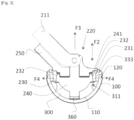
- the device referenced D as a whole ensures the gripping of a cup 100 by means of a gripping tool O for the purposes of manipulation and/or installation on the patient (not illustrated).
- This tool O comprises a handle 200 with at one end a grip 210 and at another end called a gripping end a gripping module 220.
- Said gripping module 220 is controlled by the action of the user (not shown) on a lever blade 211 associated with the handle 200 to move from a retaining position to a rest position and vice versa.
- the user actuates the lever blade 211 by moving the pivoting lever from the illustrated rest position to a working position (not shown) by pivoting according to the arrow F1
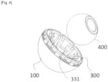
- the device D comprises a mechanical interface 300 fixed to the cup 100 before gripping by the tool O and with which the gripping module 220 cooperates.
- said mechanical interface 300 has a convex exterior surface 310 matching the interior surface of the cup 100 and a concave interior volume 320 with which the gripping module 220 cooperates.
- This mechanical interface 300 is composed of a plurality of slats 330 corresponding to angular portions which, radiating around the same central part 340, adopt a profile with an internal surface 331 and an external surface 332.
- Said external surface 332 forms said convex external surface 310 matching a part of the substantially circular profile of the internal surface 110 of the cup 100 (cf. figure 3 ),
- This mechanical interface 300 has an elasticity resulting from its material but also from its design.
- the convex external surface 310 formed by the external surface 332 of said slats 330 is preformed with a groove.
- peripheral 311 formed between a convex surface portion positioned at the bottom of the cup and a convex surface portion positioned at the edge 120 of the cup 100.
- This groove 311 adopts a semi-circular profile open to the outside.
- Another characteristic contributing to the elasticity of the mechanical interface 300 concerns the slots 350 separating the different strips 330. This elasticity allows the mechanical interface 300 to be retained in the cup 100.
- the mechanical interface further comprises on the outer periphery of its upper edge teeth 360 cooperating with surfaces preformed for this purpose on the rim 120 of the cup.
- the internal surface 331 of the slats 330 forms the concave internal volume 320 of the mechanical interface 300. It is preformed in the upper part of peripheral support surfaces 333 facing the central axis of the mechanical interface 300.
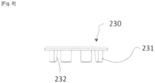
- peripheral support surfaces 333 are opposite peripheral retaining surfaces 231 preformed in the gripping module 220.
- these peripheral retaining surfaces 231 are constituted by the outer surface of projections projecting downwards from a gripping ring 230, a constituent element of the gripping module 220. These projections are also preformed with inner peripheral incised surfaces 232 facing the central axis of the gripping ring 230. As illustrated, this gripping ring 230 has a certain elasticity due to its material but also due to its configuration. Thus, the projections are spaced apart and separated by slots 233. In addition, the ring formed by the ring 230 is itself split. This slot 234 has another function which will be described later.
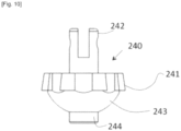
- these inner peripheral inclined surfaces 232 cooperate with outer peripheral inclined surfaces 241 arranged on the outer surface of a movable expansion shaft 240 in translation (according to the double arrow F2) and one end 242 of which is articulated to the lever blade 211 such that the movement of the lever blade 211 controlled by the rotation of the lever 212 causes the translational movement of the shaft 240,
- the outer peripheral inclined surfaces 241 are preformed on the periphery of a bulge of said shaft.
- the lower part 243 of this bulge matches the surface of the concave volume.
- an axial projection 244 is introduced into an axial orifice 370 made in the bottom of the mechanical interface 300 for the purposes of positioning and guiding the translation according to the double arrow F2.
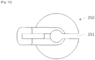
- FIG. 2 And 3 another constituent element of the gripping module is constituted by the head 250 of the gripping module 220 which guides the translation (double arrow F2) of the expansion shaft 240.
- this head 250 is split by a slot 251 so as to facilitate assembly and disassembly with the expansion shaft 240 linked to the lever blade 211.
- the slot 234 made in the gripping crown 230 participates in the same function. The complete cleaning of the instrument and the change of parts of suitable sizes and dimensions are therefore facilitated.
- the lower face of this head 250 is further preformed with a hexagonal projection 252 allowing the onentabon and the correct positioning of the gripping crown 230 preformed for this purpose.
- cup 100 cup 100, mechanical interface 300 and gripping module 220.
- the gripping of the mechanical interface 300 associated with the cup 100 by the gripping module 220 is illustrated by the figure 3 . This gripping can take place for the placement of the cup 100 or the release of the mechanical interface 300 relative to the cup 100 fixed to the patient's bone.
- the action of the user on the pivoting lever 212 according to the arrow F1 has the effect of causing the lever blade 211 to exert an axial traction according to the arrow F3 on the expansion shaft 240 which moves in translation according to this arrow.
- the external peripheral inclined surfaces 241 formed on the external surface of said movable expansion shaft 240 then exert a radial stress according to the arrows F4.
- This stress according to the arrow F4 is reflects on the interior surfaces 232 and therefore exterior surfaces 231 of the projections of the gripping crown 230 which reflects it on the slats 330 of the mechanical interface 300 guaranteeing the gripping of the gripping module 220 on the mechanical interface 300 and of the mechanical interface 300 on the cup 100.
- the mechanical interface 300 is designed to serve as a test insert for test or final heads 400.
- the concave volume 320 of the mechanical interface is sized and preformed to present support surfaces corresponding to those of the insert intended to be received after installation of the cup 100.
- the internal surface of the profile of said strips 300 has been preformed so as to form the reception and retention volume for the head,
- the cup, the mechanical interface and the head illustrated in this non-limiting embodiment adopt a so-called single mobility configuration
- the invention also applies with shapes and dimensions adapted to a so-called double mobility configuration.
Landscapes
- Health & Medical Sciences (AREA)
- Transplantation (AREA)
- Orthopedic Medicine & Surgery (AREA)
- Heart & Thoracic Surgery (AREA)
- Cardiology (AREA)
- Oral & Maxillofacial Surgery (AREA)
- Engineering & Computer Science (AREA)
- Biomedical Technology (AREA)
- Physical Education & Sports Medicine (AREA)
- Vascular Medicine (AREA)
- Life Sciences & Earth Sciences (AREA)
- Animal Behavior & Ethology (AREA)
- General Health & Medical Sciences (AREA)
- Public Health (AREA)
- Veterinary Medicine (AREA)
- Prostheses (AREA)
Claims (10)
- Greifvorrichtung (D) für ein Prothesenelement (100), wie etwa eine Pfanne,wobei das Prothesenelement (100) ein Innenvolumen umfasst, das eine Innenfläche aufweist,wobei die Vorrichtung ein Greifwerkzeug (O) umfasst, welches an bestimmten Stellen mit dem Prothesenelement (100) zusammenarbeitet, um es zu handhaben und/oder am Patienten anzubringen;wobei das Werkzeug einen Stiel (200) umfasst, der an einem Ende ein Handstück (210) und am anderen Ende ein Greifmodul (220) aufweist,wobei das Greifmodul (220) dadurch gesteuert wird, dass der Bediener auf ein Hebelblatt (211) einwirkt, welches mit dem Stiel in Verbindung steht, um von einer Haltestellung in eine Ruhestellung überzugehen und umgekehrt,wobei die Vorrichtung Folgendes umfassteine mechanische Schnittstelle (300), die zwischen dem Prothesenelement (100) und dem Greifmodul (220) eingeführt ist und die eine feste Verbindung mit dem Prothesenelement (100) eingeht,wobei die mechanische Schnittstelle (300) eine konvexe Außenfläche (310), welche zum Teil in das Innenvolumen des Prothesenelements (100) ragt und an der Innenfläche des Prothesenelements (100) anliegt, und ein konkaves Innenvolumen (320) aufweist, mit welchem das Greifmodul (220) zusammenwirkt,wobei die mechanische Schnittstelle (300) sich aus einer Mehrzahl an Lamellen (330) zusammensetzt, die sich ausgehend von demselben mittigen Abschnitt erstrecken und ein Profil mit einer inneren Fläche (320) und einer äußeren Fläche (310) annehmen, wobei die äußere Fläche (310) die konvexe Außenfläche derart bildet, dass sie vollständig oder teilweise am Profil der Innenfläche (110) des Prothesenelements (100) anliegt,wobei die mechanische Schnittstelle (300) vorgeformt ist und aus einem Material hergestellt ist, dessen Elastizität es ermöglicht, sie im Prothesenelement (100) zu halten,derart, dass- das Greifmodul (220), welches durch das Hebelblatt (211) gesteuert wird, in seiner Ruhestellung in das konkave Innenvolumen (320) eintreten und dieses verlassen kann, und dass- das Greifmodul (220), wenn es in das konkave Innenvolumen (320) eingesetzt ist, in seiner Haltestellung die Schnittstelle (300) ergreifen und das Prothesenelement (100) festhalten kann, wenn letzteres bewegt werden soll, oder die mechanische Schnittstelle (300) des Prothesenelements (100) freigeben kann, wenn dieses sich an Ort und Stelle befindet und am Knochen des Patienten befestigt ist,wobei das konkave Innenvolumen (320) der mechanischen Schnittstelle (300) derart vorgeformt ist, dass es randständige Auflageflächen (331) aufweist, mit welchen vorgeformte randständige Halteflächen im Greifmodul (220) zusammenwirken, sodass eine Bewegung, welche durch das Hebelblatt (211) gesteuert wird, sicherstellt, dass eine Spannung erzeugt wird, die dazu neigt, die randständigen Halteflächen derart auszudehnen, dass sichergestellt wird, dass das Greifmodul (220) an bestimmten Stellen eine feste Verbindung mit der mechanischen Schnittstelle (300) eingeht,DADURCH GEKENNZEICHNET, DASSdas Greifmodul (220) einen Greifkranz (230) aufweist, der außen mit den randständigen Halteflächen (231) und innen mit inneren randständigen Schrägflächen (232) versehen ist, die mit äußeren randständigen Schrägflächen (241) zusammenwirken, welche an der Außenfläche einer Aufweitungswelle (240) vorgesehen sind, welche eine Translationsbewegung ausführen kann, wobei eines ihrer Enden derart an das Hebelblatt (211) angelenkt ist, dass ein Einwirken auf das Hebelblatt (211) eine Translationsbewegung verursacht, welche zu einer Aufweitung der randständigen Halteflächen (231) oder zu deren Rückzug in die Ruhestellung führt.
- Vorrichtung (D) nach Anspruch 1, wobei die konvexe Außenfläche (310), welche von der äußeren Fläche der Lamellen (330) gebildet wird, aus einer randständigen Nut (311) vorgeformt ist, die zwischen einem konvexen Flächenabschnitt, welcher sich am Boden des Innenvolumens des Prothesenelements (100) befindet, und einem konvexen Flächenabschnitt vorgesehen ist, welcher sich an der Kante des Prothesenelements (100) befindet.
- Vorrichtung (D) nach Anspruch 1, wobei die inneren Fläche des Profils der Lamellen (330) aus den randständigen Auflageflächen (331) vorgeformt ist.
- Vorrichtung (D) nach Anspruch 1, wobei die mechanische Schnittstelle (300) Zähne (360) aufweist, die mit vorgeformten Flächen an der Kante der Pfanne (100) zusammenwirken.
- Vorrichtung (D) nach Anspruch 1, wobei das konkave Volumen (320) der mechanischen Schnittstelle (300) derart bemessen und vorgeformt ist, dass es Auflageflächen aufweist, die denjenigen einer Einlage entsprechen, welche dazu bestimmt ist, aufgenommen zu werden, nachdem das Prothesenelement eingesetzt wurde, um einen Versuchskopf oder endgültigen Kopf (400) aufzunehmen.
- Vorrichtung nach den Ansprüchen 1 und 5, wobei die innere Fläche des Profils der Lamellen derart vorgeformt ist, dass sie das Aufnahmevolumen für die Einlage bildet.
- Vorrichtung nach einem beliebigen der vorhergehenden Ansprüche, wobei es sich bei dem Material der mechanischen Schnittstelle (300) um Polypropylenharz handelt.
- Vorrichtung nach Anspruch 1, wobei das Greifmodul (220) einen Kopf (250) des Greifmoduls (220) umfasst, der die Translation der Aufweitungswelle (240) führt, wobei der Kopf (250) von einen Schlitz (251) gespalten wird.
- Vorrichtung nach Anspruch 8, wobei der Greifkranz (230) einen Schlitz (234) umfasst, der den Ring öffnet, welchen er bildet.
- Verfahren zur Verwendung einer Greifvorrichtung für ein Prothesenelement wie etwa eine Pfanne der Vorrichtung nach einem beliebigen der Ansprüche 1 bis 9, DADURCH GEKENNZEICHNET, DASS es darin besteht, die mechanische Schnittstelle (300) als versuchsweise Einlage zu verwenden.
Applications Claiming Priority (3)
| Application Number | Priority Date | Filing Date | Title |
|---|---|---|---|
| FR2012490A FR3116716B1 (fr) | 2020-12-01 | 2020-12-01 | Dispositif de préhension d’un élément prothétique telle une cupule |
| FR2012492A FR3116717A1 (fr) | 2020-12-01 | 2020-12-01 | Dispositif de préhension d’un élément prothétique telle une cupule et procédé d’utilisation d’un dispositif de préhension comme insert d’essai |
| PCT/FR2021/052152 WO2022117949A1 (fr) | 2020-12-01 | 2021-11-30 | Dispositif de préhension d'un élément prothétique telle une cupule et procédé d'utilisation d'un dispositif de préhension comme insert d'essai |
Publications (2)
| Publication Number | Publication Date |
|---|---|
| EP4255355A1 EP4255355A1 (de) | 2023-10-11 |
| EP4255355B1 true EP4255355B1 (de) | 2025-01-08 |
Family
ID=79316792
Family Applications (1)
| Application Number | Title | Priority Date | Filing Date |
|---|---|---|---|
| EP21840648.6A Active EP4255355B1 (de) | 2020-12-01 | 2021-11-30 | Vorrichtung zum greifen eines prothesenelements wie etwa eines bechers und verfahren zur verwendung einer greifvorrichtung als versuchseinsatz |
Country Status (2)
| Country | Link |
|---|---|
| EP (1) | EP4255355B1 (de) |
| WO (1) | WO2022117949A1 (de) |
Families Citing this family (1)
| Publication number | Priority date | Publication date | Assignee | Title |
|---|---|---|---|---|
| US20230190313A1 (en) * | 2021-12-22 | 2023-06-22 | Howmedica Osteonics Corp. | Screw-Through Acetabular Cup System and Methods of Using the Same |
Family Cites Families (4)
| Publication number | Priority date | Publication date | Assignee | Title |
|---|---|---|---|---|
| FR2850010B1 (fr) * | 2003-01-17 | 2005-12-02 | Tornier Sa | Ancillaire de pose d'un cotyle prothetique pour une prothese de hanche |
| GB0808284D0 (de) * | 2008-05-07 | 2008-06-11 | Benoist Girard Sas | |
| FR3059892B1 (fr) * | 2016-12-13 | 2021-04-23 | Amplitude | Ancillaire de pose d’une cupule pour implant cotyloidien de prothese totale de hanche |
| FR3066908B1 (fr) * | 2017-05-31 | 2019-07-19 | Science Et Medecine | Ensemble orthopedique comprenant une cupule et un appareil pour la mise en place de cette cupule dans une cavite anatomique |
-
2021
- 2021-11-30 EP EP21840648.6A patent/EP4255355B1/de active Active
- 2021-11-30 WO PCT/FR2021/052152 patent/WO2022117949A1/fr not_active Ceased
Also Published As
| Publication number | Publication date |
|---|---|
| WO2022117949A1 (fr) | 2022-06-09 |
| EP4255355A1 (de) | 2023-10-11 |
Similar Documents
| Publication | Publication Date | Title |
|---|---|---|
| EP2449985B2 (de) | Orthopädisches Frässwerkzeug zum Vorbereitung von Knochen, insbesondere zum Vorbereitung von Schultergelenkpfanne | |
| EP1438936B1 (de) | Hilfsinstrument zum Einsetzen einer prothetischen Gelenkpfanne für eine Hüftprothese | |
| EP1408812B1 (de) | Wirbelverbindungsvorrichtung | |
| EP1611872B1 (de) | Schulter- oder Hüftprothese | |
| EP0959822B1 (de) | Satz von humeruskopfprothesen | |
| EP2061390B1 (de) | Implantierbare orthopädische vorrichtung, im besonderen für die halswirbelsäule | |
| EP0841042A1 (de) | Satz von Hilfsinstrumenten zum Einsetzen von Hüftprothesenpfannen und einsetzfertiger Pfannenprothesensatz | |
| EP1575433A2 (de) | Fixierungssystem für knochenplatte | |
| EP2548535A1 (de) | Chirurgisches Instrument zur Entfernung einer Prothese | |
| FR2645433A1 (fr) | Cupule destinee a etre fixee sans ciment pour prothese totale de la hanche | |
| FR2857850A1 (fr) | Materiel d'osteosynthese vertebrale | |
| WO1997047257A1 (fr) | Prothese totale de hanche destinee a etre posee par voie endo-articulaire et son dispositif ancillaire | |
| FR2896684A1 (fr) | Implant tibial a tige offset | |
| FR2773469A1 (fr) | Equipement chirurgical pour l'implantation d'une prothese totale d'epaule, et prothese totale d'epaule constitutive | |
| FR2807313A1 (fr) | Ensemble retracteur orthopedique de tissus mous notamment pour la chirurgie du rachis | |
| FR3093637A3 (fr) | Ensemble formé par une embase d'ancrage osseux faisant partie d'une prothèse d'articulation et par au moins une vis de fixation de cette embase à un os | |
| FR2926719A1 (fr) | Ensemble compose d'une embase tibiale et d'un insert tibial et prothese comprenant un tel ensemble | |
| EP2548523A1 (de) | Chirurgenbesteck | |
| EP4255355B1 (de) | Vorrichtung zum greifen eines prothesenelements wie etwa eines bechers und verfahren zur verwendung einer greifvorrichtung als versuchseinsatz | |
| FR2917288A1 (fr) | Outillage pour la mise en place d'une cupule d'une prothese de hanche a double mobilite et cupule d'une telle prothese | |
| EP3772346A1 (de) | Schädeldeckenfixierer | |
| FR3066908B1 (fr) | Ensemble orthopedique comprenant une cupule et un appareil pour la mise en place de cette cupule dans une cavite anatomique | |
| FR2948013A1 (fr) | Cupule metallique pour implant cotyloidien | |
| FR3116716A1 (fr) | Dispositif de préhension d’un élément prothétique telle une cupule | |
| FR3116717A1 (fr) | Dispositif de préhension d’un élément prothétique telle une cupule et procédé d’utilisation d’un dispositif de préhension comme insert d’essai |
Legal Events
| Date | Code | Title | Description |
|---|---|---|---|
| STAA | Information on the status of an ep patent application or granted ep patent |
Free format text: STATUS: UNKNOWN |
|
| STAA | Information on the status of an ep patent application or granted ep patent |
Free format text: STATUS: THE INTERNATIONAL PUBLICATION HAS BEEN MADE |
|
| PUAI | Public reference made under article 153(3) epc to a published international application that has entered the european phase |
Free format text: ORIGINAL CODE: 0009012 |
|
| STAA | Information on the status of an ep patent application or granted ep patent |
Free format text: STATUS: REQUEST FOR EXAMINATION WAS MADE |
|
| 17P | Request for examination filed |
Effective date: 20230526 |
|
| AK | Designated contracting states |
Kind code of ref document: A1 Designated state(s): AL AT BE BG CH CY CZ DE DK EE ES FI FR GB GR HR HU IE IS IT LI LT LU LV MC MK MT NL NO PL PT RO RS SE SI SK SM TR |
|
| DAV | Request for validation of the european patent (deleted) | ||
| DAX | Request for extension of the european patent (deleted) | ||
| GRAP | Despatch of communication of intention to grant a patent |
Free format text: ORIGINAL CODE: EPIDOSNIGR1 |
|
| STAA | Information on the status of an ep patent application or granted ep patent |
Free format text: STATUS: GRANT OF PATENT IS INTENDED |
|
| INTG | Intention to grant announced |
Effective date: 20240722 |
|
| GRAS | Grant fee paid |
Free format text: ORIGINAL CODE: EPIDOSNIGR3 |
|
| GRAA | (expected) grant |
Free format text: ORIGINAL CODE: 0009210 |
|
| STAA | Information on the status of an ep patent application or granted ep patent |
Free format text: STATUS: THE PATENT HAS BEEN GRANTED |
|
| AK | Designated contracting states |
Kind code of ref document: B1 Designated state(s): AL AT BE BG CH CY CZ DE DK EE ES FI FR GB GR HR HU IE IS IT LI LT LU LV MC MK MT NL NO PL PT RO RS SE SI SK SM TR |
|
| REG | Reference to a national code |
Ref country code: GB Ref legal event code: FG4D Free format text: NOT ENGLISH |
|
| REG | Reference to a national code |
Ref country code: CH Ref legal event code: EP |
|
| REG | Reference to a national code |
Ref country code: DE Ref legal event code: R096 Ref document number: 602021024801 Country of ref document: DE |
|
| REG | Reference to a national code |
Ref country code: IE Ref legal event code: FG4D Free format text: LANGUAGE OF EP DOCUMENT: FRENCH |
|
| P01 | Opt-out of the competence of the unified patent court (upc) registered |
Free format text: CASE NUMBER: APP_11764/2025 Effective date: 20250311 |
|
| REG | Reference to a national code |
Ref country code: LT Ref legal event code: MG9D |
|
| REG | Reference to a national code |
Ref country code: NL Ref legal event code: MP Effective date: 20250108 |
|
| REG | Reference to a national code |
Ref country code: AT Ref legal event code: MK05 Ref document number: 1757862 Country of ref document: AT Kind code of ref document: T Effective date: 20250108 |
|
| PG25 | Lapsed in a contracting state [announced via postgrant information from national office to epo] |
Ref country code: NL Free format text: LAPSE BECAUSE OF FAILURE TO SUBMIT A TRANSLATION OF THE DESCRIPTION OR TO PAY THE FEE WITHIN THE PRESCRIBED TIME-LIMIT Effective date: 20250108 |
|
| PG25 | Lapsed in a contracting state [announced via postgrant information from national office to epo] |
Ref country code: RS Free format text: LAPSE BECAUSE OF FAILURE TO SUBMIT A TRANSLATION OF THE DESCRIPTION OR TO PAY THE FEE WITHIN THE PRESCRIBED TIME-LIMIT Effective date: 20250408 |
|
| PG25 | Lapsed in a contracting state [announced via postgrant information from national office to epo] |
Ref country code: FI Free format text: LAPSE BECAUSE OF FAILURE TO SUBMIT A TRANSLATION OF THE DESCRIPTION OR TO PAY THE FEE WITHIN THE PRESCRIBED TIME-LIMIT Effective date: 20250108 |
|
| PG25 | Lapsed in a contracting state [announced via postgrant information from national office to epo] |
Ref country code: PL Free format text: LAPSE BECAUSE OF FAILURE TO SUBMIT A TRANSLATION OF THE DESCRIPTION OR TO PAY THE FEE WITHIN THE PRESCRIBED TIME-LIMIT Effective date: 20250108 |
|
| PG25 | Lapsed in a contracting state [announced via postgrant information from national office to epo] |
Ref country code: ES Free format text: LAPSE BECAUSE OF FAILURE TO SUBMIT A TRANSLATION OF THE DESCRIPTION OR TO PAY THE FEE WITHIN THE PRESCRIBED TIME-LIMIT Effective date: 20250108 |
|
| PG25 | Lapsed in a contracting state [announced via postgrant information from national office to epo] |
Ref country code: NO Free format text: LAPSE BECAUSE OF FAILURE TO SUBMIT A TRANSLATION OF THE DESCRIPTION OR TO PAY THE FEE WITHIN THE PRESCRIBED TIME-LIMIT Effective date: 20250408 Ref country code: IS Free format text: LAPSE BECAUSE OF FAILURE TO SUBMIT A TRANSLATION OF THE DESCRIPTION OR TO PAY THE FEE WITHIN THE PRESCRIBED TIME-LIMIT Effective date: 20250508 |
|
| PG25 | Lapsed in a contracting state [announced via postgrant information from national office to epo] |
Ref country code: HR Free format text: LAPSE BECAUSE OF FAILURE TO SUBMIT A TRANSLATION OF THE DESCRIPTION OR TO PAY THE FEE WITHIN THE PRESCRIBED TIME-LIMIT Effective date: 20250108 |
|
| PG25 | Lapsed in a contracting state [announced via postgrant information from national office to epo] |
Ref country code: LV Free format text: LAPSE BECAUSE OF FAILURE TO SUBMIT A TRANSLATION OF THE DESCRIPTION OR TO PAY THE FEE WITHIN THE PRESCRIBED TIME-LIMIT Effective date: 20250108 Ref country code: PT Free format text: LAPSE BECAUSE OF FAILURE TO SUBMIT A TRANSLATION OF THE DESCRIPTION OR TO PAY THE FEE WITHIN THE PRESCRIBED TIME-LIMIT Effective date: 20250508 |
|
| PG25 | Lapsed in a contracting state [announced via postgrant information from national office to epo] |
Ref country code: GR Free format text: LAPSE BECAUSE OF FAILURE TO SUBMIT A TRANSLATION OF THE DESCRIPTION OR TO PAY THE FEE WITHIN THE PRESCRIBED TIME-LIMIT Effective date: 20250409 Ref country code: BG Free format text: LAPSE BECAUSE OF FAILURE TO SUBMIT A TRANSLATION OF THE DESCRIPTION OR TO PAY THE FEE WITHIN THE PRESCRIBED TIME-LIMIT Effective date: 20250108 |
|
| PG25 | Lapsed in a contracting state [announced via postgrant information from national office to epo] |
Ref country code: AT Free format text: LAPSE BECAUSE OF FAILURE TO SUBMIT A TRANSLATION OF THE DESCRIPTION OR TO PAY THE FEE WITHIN THE PRESCRIBED TIME-LIMIT Effective date: 20250108 |
|
| PG25 | Lapsed in a contracting state [announced via postgrant information from national office to epo] |
Ref country code: SE Free format text: LAPSE BECAUSE OF FAILURE TO SUBMIT A TRANSLATION OF THE DESCRIPTION OR TO PAY THE FEE WITHIN THE PRESCRIBED TIME-LIMIT Effective date: 20250108 |
|
| PG25 | Lapsed in a contracting state [announced via postgrant information from national office to epo] |
Ref country code: SM Free format text: LAPSE BECAUSE OF FAILURE TO SUBMIT A TRANSLATION OF THE DESCRIPTION OR TO PAY THE FEE WITHIN THE PRESCRIBED TIME-LIMIT Effective date: 20250108 |
|
| REG | Reference to a national code |
Ref country code: DE Ref legal event code: R097 Ref document number: 602021024801 Country of ref document: DE |
|
| PG25 | Lapsed in a contracting state [announced via postgrant information from national office to epo] |
Ref country code: DK Free format text: LAPSE BECAUSE OF FAILURE TO SUBMIT A TRANSLATION OF THE DESCRIPTION OR TO PAY THE FEE WITHIN THE PRESCRIBED TIME-LIMIT Effective date: 20250108 |
|
| PG25 | Lapsed in a contracting state [announced via postgrant information from national office to epo] |
Ref country code: CZ Free format text: LAPSE BECAUSE OF FAILURE TO SUBMIT A TRANSLATION OF THE DESCRIPTION OR TO PAY THE FEE WITHIN THE PRESCRIBED TIME-LIMIT Effective date: 20250108 Ref country code: EE Free format text: LAPSE BECAUSE OF FAILURE TO SUBMIT A TRANSLATION OF THE DESCRIPTION OR TO PAY THE FEE WITHIN THE PRESCRIBED TIME-LIMIT Effective date: 20250108 |
|
| PG25 | Lapsed in a contracting state [announced via postgrant information from national office to epo] |
Ref country code: RO Free format text: LAPSE BECAUSE OF FAILURE TO SUBMIT A TRANSLATION OF THE DESCRIPTION OR TO PAY THE FEE WITHIN THE PRESCRIBED TIME-LIMIT Effective date: 20250108 |
|
| PG25 | Lapsed in a contracting state [announced via postgrant information from national office to epo] |
Ref country code: SK Free format text: LAPSE BECAUSE OF FAILURE TO SUBMIT A TRANSLATION OF THE DESCRIPTION OR TO PAY THE FEE WITHIN THE PRESCRIBED TIME-LIMIT Effective date: 20250108 |
|
| PLBE | No opposition filed within time limit |
Free format text: ORIGINAL CODE: 0009261 |
|
| STAA | Information on the status of an ep patent application or granted ep patent |
Free format text: STATUS: NO OPPOSITION FILED WITHIN TIME LIMIT |