EP4254624A1 - Battery and electronic apparatus using said battery - Google Patents
Battery and electronic apparatus using said battery Download PDFInfo
- Publication number
- EP4254624A1 EP4254624A1 EP22778350.3A EP22778350A EP4254624A1 EP 4254624 A1 EP4254624 A1 EP 4254624A1 EP 22778350 A EP22778350 A EP 22778350A EP 4254624 A1 EP4254624 A1 EP 4254624A1
- Authority
- EP
- European Patent Office
- Prior art keywords
- enclosure
- flexible circuit
- battery
- lead
- electrode assembly
- Prior art date
- Legal status (The legal status is an assumption and is not a legal conclusion. Google has not performed a legal analysis and makes no representation as to the accuracy of the status listed.)
- Pending
Links
Images


Classifications
-
- H—ELECTRICITY
- H01—ELECTRIC ELEMENTS
- H01M—PROCESSES OR MEANS, e.g. BATTERIES, FOR THE DIRECT CONVERSION OF CHEMICAL ENERGY INTO ELECTRICAL ENERGY
- H01M10/00—Secondary cells; Manufacture thereof
- H01M10/42—Methods or arrangements for servicing or maintenance of secondary cells or secondary half-cells
- H01M10/425—Structural combination with electronic components, e.g. electronic circuits integrated to the outside of the casing
-
- G—PHYSICS
- G06—COMPUTING OR CALCULATING; COUNTING
- G06F—ELECTRIC DIGITAL DATA PROCESSING
- G06F1/00—Details not covered by groups G06F3/00 - G06F13/00 and G06F21/00
- G06F1/16—Constructional details or arrangements
- G06F1/1613—Constructional details or arrangements for portable computers
- G06F1/1633—Constructional details or arrangements of portable computers not specific to the type of enclosures covered by groups G06F1/1615 - G06F1/1626
- G06F1/1635—Details related to the integration of battery packs and other power supplies such as fuel cells or integrated AC adapter
-
- H—ELECTRICITY
- H01—ELECTRIC ELEMENTS
- H01M—PROCESSES OR MEANS, e.g. BATTERIES, FOR THE DIRECT CONVERSION OF CHEMICAL ENERGY INTO ELECTRICAL ENERGY
- H01M10/00—Secondary cells; Manufacture thereof
- H01M10/04—Construction or manufacture in general
-
- H—ELECTRICITY
- H01—ELECTRIC ELEMENTS
- H01M—PROCESSES OR MEANS, e.g. BATTERIES, FOR THE DIRECT CONVERSION OF CHEMICAL ENERGY INTO ELECTRICAL ENERGY
- H01M50/00—Constructional details or processes of manufacture of the non-active parts of electrochemical cells other than fuel cells, e.g. hybrid cells
- H01M50/10—Primary casings; Jackets or wrappings
- H01M50/172—Arrangements of electric connectors penetrating the casing
- H01M50/174—Arrangements of electric connectors penetrating the casing adapted for the shape of the cells
- H01M50/176—Arrangements of electric connectors penetrating the casing adapted for the shape of the cells for prismatic or rectangular cells
-
- H—ELECTRICITY
- H01—ELECTRIC ELEMENTS
- H01M—PROCESSES OR MEANS, e.g. BATTERIES, FOR THE DIRECT CONVERSION OF CHEMICAL ENERGY INTO ELECTRICAL ENERGY
- H01M50/00—Constructional details or processes of manufacture of the non-active parts of electrochemical cells other than fuel cells, e.g. hybrid cells
- H01M50/20—Mountings; Secondary casings or frames; Racks, modules or packs; Suspension devices; Shock absorbers; Transport or carrying devices; Holders
- H01M50/204—Racks, modules or packs for multiple batteries or multiple cells
- H01M50/207—Racks, modules or packs for multiple batteries or multiple cells characterised by their shape
- H01M50/209—Racks, modules or packs for multiple batteries or multiple cells characterised by their shape adapted for prismatic or rectangular cells
-
- H—ELECTRICITY
- H01—ELECTRIC ELEMENTS
- H01M—PROCESSES OR MEANS, e.g. BATTERIES, FOR THE DIRECT CONVERSION OF CHEMICAL ENERGY INTO ELECTRICAL ENERGY
- H01M50/00—Constructional details or processes of manufacture of the non-active parts of electrochemical cells other than fuel cells, e.g. hybrid cells
- H01M50/20—Mountings; Secondary casings or frames; Racks, modules or packs; Suspension devices; Shock absorbers; Transport or carrying devices; Holders
- H01M50/244—Secondary casings; Racks; Suspension devices; Carrying devices; Holders characterised by their mounting method
-
- H—ELECTRICITY
- H01—ELECTRIC ELEMENTS
- H01M—PROCESSES OR MEANS, e.g. BATTERIES, FOR THE DIRECT CONVERSION OF CHEMICAL ENERGY INTO ELECTRICAL ENERGY
- H01M50/00—Constructional details or processes of manufacture of the non-active parts of electrochemical cells other than fuel cells, e.g. hybrid cells
- H01M50/20—Mountings; Secondary casings or frames; Racks, modules or packs; Suspension devices; Shock absorbers; Transport or carrying devices; Holders
- H01M50/247—Mountings; Secondary casings or frames; Racks, modules or packs; Suspension devices; Shock absorbers; Transport or carrying devices; Holders specially adapted for portable devices, e.g. mobile phones, computers, hand tools or pacemakers
-
- H—ELECTRICITY
- H01—ELECTRIC ELEMENTS
- H01M—PROCESSES OR MEANS, e.g. BATTERIES, FOR THE DIRECT CONVERSION OF CHEMICAL ENERGY INTO ELECTRICAL ENERGY
- H01M50/00—Constructional details or processes of manufacture of the non-active parts of electrochemical cells other than fuel cells, e.g. hybrid cells
- H01M50/20—Mountings; Secondary casings or frames; Racks, modules or packs; Suspension devices; Shock absorbers; Transport or carrying devices; Holders
- H01M50/284—Mountings; Secondary casings or frames; Racks, modules or packs; Suspension devices; Shock absorbers; Transport or carrying devices; Holders with incorporated circuit boards, e.g. printed circuit boards [PCB]
-
- H—ELECTRICITY
- H01—ELECTRIC ELEMENTS
- H01M—PROCESSES OR MEANS, e.g. BATTERIES, FOR THE DIRECT CONVERSION OF CHEMICAL ENERGY INTO ELECTRICAL ENERGY
- H01M50/00—Constructional details or processes of manufacture of the non-active parts of electrochemical cells other than fuel cells, e.g. hybrid cells
- H01M50/20—Mountings; Secondary casings or frames; Racks, modules or packs; Suspension devices; Shock absorbers; Transport or carrying devices; Holders
- H01M50/289—Mountings; Secondary casings or frames; Racks, modules or packs; Suspension devices; Shock absorbers; Transport or carrying devices; Holders characterised by spacing elements or positioning means within frames, racks or packs
-
- H—ELECTRICITY
- H01—ELECTRIC ELEMENTS
- H01M—PROCESSES OR MEANS, e.g. BATTERIES, FOR THE DIRECT CONVERSION OF CHEMICAL ENERGY INTO ELECTRICAL ENERGY
- H01M50/00—Constructional details or processes of manufacture of the non-active parts of electrochemical cells other than fuel cells, e.g. hybrid cells
- H01M50/20—Mountings; Secondary casings or frames; Racks, modules or packs; Suspension devices; Shock absorbers; Transport or carrying devices; Holders
- H01M50/298—Mountings; Secondary casings or frames; Racks, modules or packs; Suspension devices; Shock absorbers; Transport or carrying devices; Holders characterised by the wiring of battery packs
-
- H—ELECTRICITY
- H01—ELECTRIC ELEMENTS
- H01M—PROCESSES OR MEANS, e.g. BATTERIES, FOR THE DIRECT CONVERSION OF CHEMICAL ENERGY INTO ELECTRICAL ENERGY
- H01M50/00—Constructional details or processes of manufacture of the non-active parts of electrochemical cells other than fuel cells, e.g. hybrid cells
- H01M50/50—Current conducting connections for cells or batteries
- H01M50/502—Interconnectors for connecting terminals of adjacent batteries; Interconnectors for connecting cells outside a battery casing
-
- H—ELECTRICITY
- H01—ELECTRIC ELEMENTS
- H01M—PROCESSES OR MEANS, e.g. BATTERIES, FOR THE DIRECT CONVERSION OF CHEMICAL ENERGY INTO ELECTRICAL ENERGY
- H01M50/00—Constructional details or processes of manufacture of the non-active parts of electrochemical cells other than fuel cells, e.g. hybrid cells
- H01M50/50—Current conducting connections for cells or batteries
- H01M50/531—Electrode connections inside a battery casing
- H01M50/54—Connection of several leads or tabs of plate-like electrode stacks, e.g. electrode pole straps or bridges
-
- H—ELECTRICITY
- H01—ELECTRIC ELEMENTS
- H01M—PROCESSES OR MEANS, e.g. BATTERIES, FOR THE DIRECT CONVERSION OF CHEMICAL ENERGY INTO ELECTRICAL ENERGY
- H01M2220/00—Batteries for particular applications
- H01M2220/30—Batteries in portable systems, e.g. mobile phone, laptop
-
- Y—GENERAL TAGGING OF NEW TECHNOLOGICAL DEVELOPMENTS; GENERAL TAGGING OF CROSS-SECTIONAL TECHNOLOGIES SPANNING OVER SEVERAL SECTIONS OF THE IPC; TECHNICAL SUBJECTS COVERED BY FORMER USPC CROSS-REFERENCE ART COLLECTIONS [XRACs] AND DIGESTS
- Y02—TECHNOLOGIES OR APPLICATIONS FOR MITIGATION OR ADAPTATION AGAINST CLIMATE CHANGE
- Y02E—REDUCTION OF GREENHOUSE GAS [GHG] EMISSIONS, RELATED TO ENERGY GENERATION, TRANSMISSION OR DISTRIBUTION
- Y02E60/00—Enabling technologies; Technologies with a potential or indirect contribution to GHG emissions mitigation
- Y02E60/10—Energy storage using batteries
Definitions
- the present disclosure relates to the field of batteries, and more specifically, to a battery and an electronic device using same.
- Electronic devices such as laptops, tablets, and mobile phones, are increasingly designed to be thin and light due to aesthetic and portability requirements.
- a battery as a key component, is substantially mounted in the same manner. That is to say, a separate battery compartment needs to be arranged in advance for the battery, and the battery and battery compartment are basically regular shapes.
- the battery usually includes multiple cells. In order to meet requirements such as outputting a voltage, outputting a current, sampling, and control, multiple connecting lines are necessarily to be arranged, which are complex in structure and occupy more space.
- the present disclosure discloses a battery and an electronic device using same, which is intended to provide a battery structure that can simplify a battery structure and improve a space utilization rate inside the electronic device and help realize thinness and lightness of the electronic device.
- a battery applicable to an electronic device, where the electronic device includes an enclosure having an accommodating space formed therein and multiple functional devices, the multiple functional devices are accommodated in the enclosure and occupy part of the accommodating space of the enclosure, and the battery includes:
- the flexible circuit further includes a wire portion, and the wire portion is integrally formed on an inner side of the housing; and the multiple connecting portions and the output terminal are arranged on the wire portion, and the connecting portions protrude from an inner side of the enclosure and extend to the corresponding lead-out portions.
- the housing includes:
- the housing includes:
- the flexible circuit includes:
- the flexible circuit layer includes multiple wire sections, the multiple wire sections are predetermined based on the predetermined serial/parallel relationship and positions of the lead-out portion and the output terminal;
- the insulating layer is formed by coating an insulating material on a surface of the wire section.
- each of the electrode assemblies includes multiple positive plates, multiple separators, and multiple negative plates that are arranged in a stack, each of the positive plates is provided with a positive tab, each of the negative plates is provided with a negative tab;
- the insulating layer is an insulating film; and the insulating film is attached to the outer side of the flexible circuit layer and engaged with the housing.
- the present disclosure further discloses an electronic device, including:
- the flexible circuit is integrally formed on the inner side of the enclosure by using convenient features of forming and laying, which can simplify the circuit design of the battery. In this way, the utilization rate of the internal space of the electronic device can be improved, and the lightness and thinness of the electronic device can be easily realized.
- the electronic device 100 includes an enclosure 10, a battery 20, and a functional device 30.
- the enclosure 10 is formed with accommodating space, which is configured to accommodate the battery 20 and the functional device 30.
- the functional device 30 is mounted to the enclosure 10 and occupies part of the accommodating space.
- the battery 20 substantially occupies remaining space of the accommodating space.
- the electronic device 100 may be a portable device such as a notebook computer and a tablet computer, or may be other smart electronic products, such as a mobile phone and a wearable device.
- the enclosure 10 corresponds to a housing of a host part of the notebook computer
- the functional device 30 mainly include a main board, a CPU, a hard disk, a memory, a graphics card, a sound card, a heat sink, and the like.
- the battery 30 is a power supply battery for the notebook computer.
- a side facing internal accommodating space of the housing occupies part of the accommodating space.
- specifications of the functional device are diversified, and overall dimensions are different.
- the remaining accommodating space is irregular and uneven in shape due to an influence of concave and convexity of the functional devices and a spacing of an arrangement between the functional devices.
- the enclosure 10 may be provided with an independent battery compartment, and the battery compartment is arranged in a regular shape to facilitate design and processing.
- the battery compartment needs to avoid the functional device 30 as a whole, resulting in unavailability of a number of irregular spaces.
- the functional device 30 is mounted to the enclosure 10 and occupies part of the accommodating space, and the battery 20 substantially occupies remaining space of the accommodating space.
- the "substantially” here means that the foregoing remaining space cannot be strictly occupied due to a factor such as a machining accuracy limitation, an assembly requirement, and an electrical safety requirement. Therefore, the battery 20 can generally occupy the rest of the accommodating space, and can reflect that the battery 20 and the functional device 30 avoid each other and complement each other in volume to use a volume of the accommodating space as much as possible.
- the battery 20 disclosed in the embodiment of the present disclosure includes a housing 210, multiple electrode assemblies 220, and a flexible circuit 230.
- the multiple electrode assemblies 220 have predetermined overall dimensions and are arranged according to predetermined positions respectively.
- the electronic device 100 needs to implement a specific function, and the functional device 30 may be arranged in the enclosure 10 prior to the battery 20.
- the shape and distribution of the remaining space within the enclosure 10 are also substantially determined.
- overall dimensions and positions of the multiple electrode assemblies 220 can be divided in advance according to the shape and distribution of the remaining space.
- the series and/or parallel relationship between the multiple electrode assemblies 220 can be preset to set an output current, voltage, and the like.
- At least two of the electrode assemblies 220 have different heights, which can be set according to the volume occupation of the functional device 30.
- each of the electrode assemblies 220 may be arranged in a mutual avoidance relationship with the multiple functional devices 30 in height. That is to say, when the battery 20 is placed in the accommodating space, the functional device 30 of the electronic device 100 occupies part of the accommodating space.
- the overall dimension and the position arrangement of the electrode assemblies 220 is preset according to the arrangement of the functional device 30, and the electrode assemblies 220 is set to a height that matches the corresponding position of the functional device 30.
- the height of the electrode assembly 220 provided corresponding thereto is correspondingly set lower when the height of the functional device 30 is higher, and the height of the electrode assembly 220 provided corresponding thereto is correspondingly set higher when the height of the functional device 30 is lower.
- the battery 20 substantially occupies the rest of the accommodating space, and realizes the full utilization of the accommodating space.
- a shape of the electrode assembly 220 may be a regular shape, so as to be formed by a winding process.
- the electrode assembly 220 may be substantially constructed as a rectangular shape.
- the electrode assembly 220 can may be set to an irregular shape, that is, a special-shaped shape, such as a diamond, a fan, and a trapezoid.
- the electrode assembly 220 may be molded in a laminated manner.
- the shape of the electrode assembly 220 can be set according to a setting requirement of the accommodating space.
- the predetermined position of the electrode assembly 220 is provided with a lead-out portion 2201, so as to realize the series and parallel connection between the multiple electrode assemblies 220.
- the predetermined position of the housing 210 protrudes outward, and multiple accommodating grooves 2121 are correspondingly formed inside the housing 210.
- the multiple accommodating grooves 2121 match the multiple electrode assemblies 220 in the overall dimensions, so as to correspondingly accommodate the multiple electrode assemblies 220.
- the flexible circuit 230 is integrally formed with the housing 210 and laid based on a predetermined serial/parallel relationship of the multiple electrode assemblies 220 and a position of the lead-out portion 2201.
- the flexible circuit 230 includes an output terminal 2303 and multiple connecting portions 2302.
- the multiple connecting portions 2302 are configured to be connected to the corresponding lead-out portions 2201 to electrically connect the multiple electrode assemblies 220.
- the output terminal 2303 extends out of the housing 210 for leading out power.
- the flexible circuit 230 includes a wire portion 2301, the connecting portion 2302, and the output terminal 2303.
- the wire portion 2301 is integrally formed on the inner side of the housing 210.
- the multiple connecting portions 2302 and the output terminal 2303 are arranged on the wire portion 2301, and each of the connecting portions 2302 protrudes from the inner side of the housing 210 and extends to the corresponding lead-out portion 2201.
- the series and/or parallel relationship between the multiple electrode assemblies 220 can be preset to set an output current, voltage, and the like. If a common circuit with a coating film is used to complete the connection of the multiple electrode assemblies 220, the non-foldability of the common circuit weakens the safety performance of the battery. Besides, an overall layout is messy and complicated if the circuit is directly connected inside the battery. Therefore, the present disclosure solves a risk caused by the non-foldability of the common circuit by using the flexible circuit that can be freely bent, wound, and folded.
- the housing 210 includes a first enclosure 2110 and a second enclosure 2120.
- the first enclosure 2110 is substantially located in a same plane.
- the first enclosure 2110 is substantially a flat plate-like structure.
- the second enclosure 2120 is arranged opposite to the first enclosure 2110 and defining the accommodating space together with the first enclosure 2110.
- the second enclosure 2120 is recessed at a predetermined position away from the first enclosure 2110 to form the multiple accommodating grooves 2121.
- the housing 210 may be an aluminum-plastic film, and the first enclosure 2110 is a relatively flat side of the aluminum-plastic film.
- the second enclosure 2120 can be drawn deep to form the accommodating groove 2121 that is recessed at the predetermined position.
- the aluminum-plastic film can be scoured to a different depth based on a specific position.
- the flexible circuit 230 cannot be stamped, so the flexible circuit 230 needs to be designed to a bottom plane film of the aluminum-plastic film without punching, and the connecting portion 2302 corresponding to the position of each electrode assembly 220 is reserved.
- the positive/negative lead-out portions 2201 at each position of the electrode assembly 230 are electrically connected with the corresponding connecting portions 2302 of the flexible circuit 230, respectively.
- the connecting portion 2302 of the electrode assembly 220 is usually formed by centralized spot welding of the tab of each electrode plate.
- the lead-out portion 2201 and the connecting portion 2302 may be electrically connected by spot welding or riveting to complete the serial/parallel connection between the electrode assemblies 220 inside the battery 20.
- the flexible circuit 230 may form an integral structure with the first enclosure 2110, or may form an integral structure with the second enclosure 2120.
- the flexible circuit 230 may be attached to the inner wall of the first enclosure 2110. In another implementation, the flexible circuit 230 may be attached to the inner wall of the second enclosure 2120. Since the flexible circuit 230 cannot be scoured and drawn, the flexible circuit needs to be distributed in a non-drawing area 2122 of the second enclosure 2120.
- the flexible circuit 230 includes a flexible circuit layer and an insulating layer 2304.
- the flexible circuit layer is attached to the inner wall of the housing 210.
- the flexible circuit layer may include a wire portion 2301, the connecting portion 2302, and the output terminal 2303.
- the positive/negative lead-out portions 2201 at each position of the electrode assembly 230 may alternatively be arranged close to an inner surface of the first enclosure 2110.
- the connecting portion 2302 may be bent by the inner wall of the first enclosure 2110 and extend to the positive/negative lead-out portion 2201 at the corresponding position of the electrode assembly 230.
- the insulating layer 2304 is coated on the outer side of the flexible circuit layer and exposes the connecting portion 2302 and the output terminal 2303. In this way, the insulating layer 2304 isolates a side of the flexible circuit layer close to the electrode assembly 220, plays an insulating protection role, and at the same time prevents an electrolyte in the later battery from corroding the line.
- the flexible circuit layer includes multiple wire sections, and the multiple wire sections are predetermined based on the predetermined serial/parallel relationship and positions of the lead-out portion 2201 and the output terminal 2303. At least one of the connecting portion 2302 and the output terminal 2303 is integrally preformed with one of the wire sections.
- the battery 20 includes five electrode assemblies 220, which are specifically referred to as a first electrode assembly 2210, a second electrode assembly 2220, a third electrode assembly 2230, a fourth electrode assembly 2240, and a fifth electrode assembly 2250.
- These electrode assemblies 220 are rectangular in shape, and each electrode assembly has three dimensions: length, width, and height. The width and length are respectively the dimensions of the electrode assembly in two directions perpendicular to the height direction. As described above, at least two of the five electrode assemblies 220 have different heights.
- the functional devices 30 in the electronic device 100 have different specifications, therefore, the five electrode assemblies 220 have different heights generally, and at least two electrode assemblies 220 have different widths, and/or at least two electrode assemblies 220 have different lengths among the five electrode assemblies 220.
- the length, width, and height of the first electrode assembly to the fifth electrode assembly are different from each other.
- the implementation may be set according to a specific requirement.
- the first electrode assembly 2210, the second electrode assembly 2220, the third electrode assembly 2230, the fourth electrode assembly 2240, and the fifth electrode assembly 2250 are arranged in a predetermined form, and a spacing is defined between the adjacent electrode assemblies.
- the lead-out portion 2201 of each fifth electrode assembly 220 needs to be connected with the flexible circuit 230, and is arranged toward the spacing accordingly.
- the positive lead-out portion and the negative lead-out portion of the second electrode assembly 2220 are arranged in a spacing between the second electrode assembly 2220 and the third electrode assembly 2230.
- the positive lead-out portion and the negative lead-out portion of the second electrode assembly 2220 are arranged in a spacing between the second electrode assembly 2220 and the third electrode assembly 2230.
- the positive lead-out portion and the negative lead-out portion of the third electrode assembly 2230 are arranged in a spacing between the third electrode assembly 2230 and the fifth electrode assembly 2250.
- the positive lead-out portion of the fourth electrode assembly 2240 and the fifth electrode assembly 2250 are arranged in a spacing between the fourth electrode assembly 2240 and the fifth electrode assembly 2250.
- the negative lead-out portion of the fifth electrode assembly 2250 is arranged in a spacing between the fifth electrode assembly 2250 and the first electrode assembly 2210.
- the positive lead-out portion of the first electrode assembly 2210, the negative lead-out portion, and the negative lead-out portion of the fourth electrode assembly 2240 are arranged toward an outer peripheral side of the respective electrode assemblies.
- the wire portion 2301 of the flexible circuit 230 can be arranged into four sections, that is, a first wire section 2310, a second wire section 2320, a third wire section 2330, and a fourth wire section 2340.
- the first wire section 2310 is connected with the positive lead-out portion of the first electrode assembly 2210, and is multiplexed as the positive electrode output terminal of the battery 20.
- One end of the second wire section 2320 is connected with the negative lead-out portion of the first electrode assembly 2210, and the other end separates two connecting portions 2302, which are respectively connected with the positive lead-out portions of the second electrode assembly 2220 and the third electrode assembly 2230.
- Both ends of the third wire section 2330 are each divided into two connecting portions 2302.
- the two connecting portions 2302 at one end are respectively connected with the negative lead-out portion of the second electrode assembly 2220 and the negative lead-out portion of the fifth electrode assembly 2250, the two connecting portions 2302 at the other end are respectively connected with the positive lead-out portion of the fourth electrode assembly 2240 and the positive lead-out portion of the fifth electrode assembly 2250.
- One end of the fourth wire section 2340 is divided into two connecting portions 2320, which are respectively connected with the negative lead-out portion of the fourth electrode assembly 2240 and the negative lead-out portion of the fifth electrode assembly 2250, the other end is multiplexed as the negative output terminal of the battery 20.
- the first electrode assembly 2210, the second electrode assembly 2220 and the third electrode assembly 2230 after being connected in parallel, and the series connection of the fourth electrode assembly 2240 and the fifth electrode assembly 2250 after being connected in parallel can be realized, and the positive output and the negative output of the battery 20 may be realized at the same time.
- the insulating layer 2304 covers the multiple wire sections.
- the insulating layer 2304 is formed by coating an insulating material on a surface of the wire section.
- the insulating layer 2304 is an insulating film, and the insulating film is attached to an outer side of the flexible circuit layer 2312 and combined with the housing 210.
- the housing 210 may be an aluminum-plastic film, and the flexible circuit layer and the insulating layer 2304 may alternatively be designed into the aluminum-plastic film in advance.
- the tab is extracted by embedding a flexible circuit layer and an insulating layer 2304 with corrosion resistance and insulation in advance in an original nylon layer 2111, an Al layer 2112, and a PP layer 2113 of the aluminum-plastic film, and drawing the positive and negative tabs are through the positive and negative tab pins.
- the electrode assembly 220 is the electrode core, and includes a positive plate 221, a separator 222, and a negative plate 223.
- the electrode assembly 220 includes multiple includes multiple positive plates 221, multiple separators 222, and multiple negative plates 223 that are arranged in a stack.
- a positive tab 2211 is arranged on the positive plate 221, and a negative tab 2231 is arranged on the negative plate 223.
- each electrode assembly 220 The multiple positive tabs 2211 of each electrode assembly 220 are connected together to form a positive lead-out portion, and the multiple negative tabs 2231 are connected together to form a negative lead-out portion.
- the connecting portion 2302 protrudes from the flexible circuit 230 and extends to a position docked with the corresponding positive lead-out portion or the negative lead-out portion, so as to form an electrical connection with the corresponding positive lead-out portion or the negative lead-out portion.
- the functional device 30 of the electronic device 100 and the shape of the battery 20 engage with each other, the electrode assembly 220 and the corresponding functional device 30 form a mutual avoidance and complementary relationship in occupation of the space, so as to make full use of the accommodating space.
- the flexible circuit 230 is integrally formed on the inner side of the enclosure 210 due to the convenient molding and layout, so that the circuit design of the battery 20 can be simplified, and the design and layout of the battery 20 can be simplified. In this way, the utilization rate of the internal space of the electronic device 100 can be improved, and the thinness and lightness of the electronic device 100 can be easily realized.
- the flexible circuit 230 is accommodated in the housing and laid based on a predetermined serial/parallel relationship of the multiple electrode assemblies 220 and a position of the lead-out portion 2201 to electrically connect the multiple electrode assemblies. Wires are arranged in the housing 210 of the battery 20, and the electrical connection of the electrode assembly 220 is realized.
- the output terminal extends out of the housing for electrical lead-out, which can simplify an external circuit and reduce occupation of an internal space of the electronic device 100 by an external circuit and a component.
- the flexible circuit further includes a wire portion 2301 and multiple connecting portions 2302 arranged on the wire portion 2301.
- the wire portion 2301 is laid on a circumferential side of the electrode assembly 220 based on the predetermined serial/parallel relationship of the multiple electrode assemblies 220 and the position of the lead-out portion 2201.
- the multiple connecting portions 2302 are arranged on the wire portion 2301 and electrically connected with the lead-out portion 2201 at a corresponding position.
- the output terminal 2303 is arranged on the wire portion 2301.
- the electrode assembly 220 may be made by winding a positive plate, a separator, and a negative plate.
- a tab is reserved on the positive plate and the negative plate.
- the lead-out portion 2201 may correspondingly include a positive lead-out portion and a negative lead-out portion that are formed after the winding by respectively soldering the positive tabs together and soldering the negative tabs together.
- the lead-out portion 2201 may be arranged on a side surface of the electrode assembly 220, and the lead-out portion 2201 of the multiple electrode assemblies 220 may be substantially arranged on a same plane, to facilitate arrangement of the flexible circuit 230.
- the wire portion 2301 may include multiple wire sections predetermined based on the predetermined serial/parallel relationship and the position of the lead-out portion. Since the multiple electrode assemblies 220 are different in size and specification to meet the requirements of space occupation, in order to meet the requirement for output power, the electrode cores need to be connected according to the predetermined series and parallel relationship.
- the wire portion 2301 is preset as multiple wire sections, which can more conveniently complete the predetermined serial/parallel connection, especially the series connection, according to the arrangement of the electrode assembly 220.
- At least one of the connecting portion 2302 and the output terminal 2303 may be integrally preformed with one of the wire sections.
- the connecting portion 2302 can be integrally formed with the corresponding wire section, and the connecting portion 2302 is located at a terminal of the corresponding wire section.
- the output terminal 2303 includes a positive output terminal and a negative output terminal, one of which is integrally formed with a wire section, and the other may be formed by a wire section.
- An outer side of the wire portion is covered with an insulating film 240, to achieve an electrical insulation protection. Apart of the connecting portion 2302 and the output terminal 2303 are exposed to facilitate electrical connection.
- a spacing may be defined between adjacent electrode assemblies 220 as setting the arrangement of the multiple electrode assemblies 220.
- the lead-out portion 2201 of each fifth electrode assembly 220 needs to be connected with the flexible circuit 230, and is arranged toward the spacing accordingly.
- a part of the wire portion 2301 located between adjacent electrode assemblies 220 is embedded in a corresponding spacing.
- the electrical connection between the flexible circuit 230 and the lead-out portion 2201 of the electrode assembly 220 is facilitated.
- the lead-out portion 2201 of the electrode assembly 220 needs to occupy part of the space, therefore, the wire portion 2301 of the flexible circuit 230 is embedded in the spacing that needs to be reserved, which is equivalent to multiplexing this part of the space. As a result, the space utilization rate is improved and the wiring is facilitated.
- the housing 210 may include a first enclosure 2110 and a second enclosure 2120.
- the first enclosure 2110 is substantially located in the same plane, that is, the first enclosure 2110 is substantially a flat film, forming a flat side of the housing 210.
- the "substantially” here can be used for a tolerance and an error caused by an impact of machining accuracy, or a local special shape introduced due to a local design requirement, and the like. In all, the first enclosure 2110 is generally flat.
- the second enclosure 2120 is recessed at a predetermined position away from the first enclosure 2110 to form the multiple accommodating grooves 2121.
- a shape of each accommodating groove 2121 matches the corresponding electrode assembly 220.
- Peripheral sides of the first enclosure 2110 and the second enclosure 2120 are respectively provided an edge sealing portion.
- the peripheral sides of the first enclosure 2110 and the second enclosure 2120 is sealed and connected through the edge sealing portion, so that the electrode assembly 220 and the flexible circuit 230 are packaged in the enclosure 210.
- An outer side of the output terminal 2303 is covered with a sealing adhesive layer (not shown in the figure).
- the output terminal 2303 extends out of the housing 210 between the two edge sealing portions; and the output terminal 2303 is sealed and connected with a corresponding position of the edge sealing portion through the sealing adhesive layer for leading out power of the battery 20.
- the lead-out portion 2201 of the electrode assembly 220 and the flexible circuit 230 are arranged close to the first enclosure 2110. Neat wiring can be formed by using the flat first enclosure 2110, and late stress deformation can be avoided as much as possible.
Landscapes
- General Chemical & Material Sciences (AREA)
- Electrochemistry (AREA)
- Chemical Kinetics & Catalysis (AREA)
- Chemical & Material Sciences (AREA)
- Engineering & Computer Science (AREA)
- Computer Hardware Design (AREA)
- Manufacturing & Machinery (AREA)
- Theoretical Computer Science (AREA)
- Microelectronics & Electronic Packaging (AREA)
- Life Sciences & Earth Sciences (AREA)
- Biophysics (AREA)
- General Physics & Mathematics (AREA)
- General Engineering & Computer Science (AREA)
- Physics & Mathematics (AREA)
- Human Computer Interaction (AREA)
- Power Engineering (AREA)
- Connection Of Batteries Or Terminals (AREA)
- Sealing Battery Cases Or Jackets (AREA)
- Battery Mounting, Suspending (AREA)
Abstract
Description
- The present disclosure claims priority to
Chinese Patent Application No. 202110340406.4, filed on March 30, 2021 - The present disclosure relates to the field of batteries, and more specifically, to a battery and an electronic device using same.
- Electronic devices, such as laptops, tablets, and mobile phones, are increasingly designed to be thin and light due to aesthetic and portability requirements. Generally, an overall dimension and an arrangement of a functional component inside the electronic device vary, but a battery, as a key component, is substantially mounted in the same manner. That is to say, a separate battery compartment needs to be arranged in advance for the battery, and the battery and battery compartment are basically regular shapes. In order to avoid other functional components, use of part of the space needs to be given up, which is not conducive to the thinness and lightness of the electronic device. Meanwhile, the battery usually includes multiple cells. In order to meet requirements such as outputting a voltage, outputting a current, sampling, and control, multiple connecting lines are necessarily to be arranged, which are complex in structure and occupy more space.
- Based on the above, the present disclosure discloses a battery and an electronic device using same, which is intended to provide a battery structure that can simplify a battery structure and improve a space utilization rate inside the electronic device and help realize thinness and lightness of the electronic device.
- The solutions are as follows.
- A battery, applicable to an electronic device, where the electronic device includes an enclosure having an accommodating space formed therein and multiple functional devices, the multiple functional devices are accommodated in the enclosure and occupy part of the accommodating space of the enclosure, and the battery includes:
- multiple electrode assemblies, respectively arranged in a predetermined size specification and arranged at predetermined positions to substantially occupy the rest of the accommodating space, where each of the predetermined positions of the electrode assemblies is provided with a lead-out portion;
- a housing, where a predetermined position of the housing protrudes outward and multiple accommodating grooves are correspondingly formed inside, and the multiple accommodating grooves match the overall dimensions of the multiple electrode assemblies to correspondingly accommodate the multiple electrode assemblies; and
- a flexible circuit, integrally formed with the housing and laid based on a predetermined serial/parallel relationship of the multiple electrode assemblies and a position of the lead-out portion, where the flexible circuit includes an output terminal and multiple connecting portions, the multiple connecting portions are configured to be connected with the corresponding lead-out portions to electrically connect the multiple electrode assemblies; and the output terminal extends out of the housing for leading out power.
- In a preferred implementation, the flexible circuit further includes a wire portion, and the wire portion is integrally formed on an inner side of the housing; and
the multiple connecting portions and the output terminal are arranged on the wire portion, and the connecting portions protrude from an inner side of the enclosure and extend to the corresponding lead-out portions. - In a preferred implementation, the housing includes:
- a first enclosure, substantially located on a same plane; and
- a second enclosure, arranged opposite to the first enclosure and defining the accommodating space together with the first enclosure, where the predetermined position of the second enclosure is recessed away from the first enclosure to form the multiple accommodating grooves; and
- the flexible circuit is attached to an inner wall of the first enclosure.
- In a preferred implementation, the housing includes:
- a first enclosure, substantially located on a same plane; and
- a second enclosure, arranged opposite to the first enclosure and defining the accommodating space together with the first enclosure, where the predetermined position of the second enclosure is recessed away from the first enclosure to form the multiple accommodating grooves; and
- the flexible circuit is attached to an inner wall of the second enclosure and arranged in a non-drawing area of the second enclosure.
- In a preferred implementation, the flexible circuit includes:
- a flexible circuit layer, attached to an inner wall of the housing and including the wire portion, the connecting portion, and the output terminal; and
- an insulating layer, covering an outer side of the flexible circuit layer and exposing the connecting portion and the output terminal.
- In a preferred implementation, the flexible circuit layer includes multiple wire sections, the multiple wire sections are predetermined based on the predetermined serial/parallel relationship and positions of the lead-out portion and the output terminal;
- at least one of the connecting portion and the output terminal is integrally preformed with one of the wire sections; and
- the insulating layer covers the multiple wire sections.
- In a preferred implementation, the insulating layer is formed by coating an insulating material on a surface of the wire section.
- In a preferred implementation, each of the electrode assemblies includes multiple positive plates, multiple separators, and multiple negative plates that are arranged in a stack, each of the positive plates is provided with a positive tab, each of the negative plates is provided with a negative tab;
- multiple positive tabs of each electrode assembly are connected together to form a positive lead-out portion, multiple negative tabs are connected together to form a negative lead-out portion; and
- the connecting portion protrudes from the wire section and extends to a position docked with the corresponding positive lead-out portion or the negative lead-out portion.
- In a preferred implementation, the insulating layer is an insulating film; and the insulating film is attached to the outer side of the flexible circuit layer and engaged with the housing.
- The present disclosure further discloses an electronic device, including:
- an enclosure, having an accommodating space formed therein; and
- multiple functional devices, mounted to the enclosure and occupying part of the accommodating space, where
- the electronic device further includes the battery; and
- the battery substantially occupies the rest of the accommodating space.
- In the battery and the electronic device using same, the functional device of the electronic device and the shape of the battery engage with each other, the electrode assembly and the corresponding functional device form a mutual avoidance and complementary relationship in occupation of the space, so as to make full use of the accommodating space. In addition, the flexible circuit is integrally formed on the inner side of the enclosure by using convenient features of forming and laying, which can simplify the circuit design of the battery. In this way, the utilization rate of the internal space of the electronic device can be improved, and the lightness and thinness of the electronic device can be easily realized.
- The above-mentioned and other objects and advantages of the present disclosure are described in detail below in conjunction with the accompanying drawings.
-
FIG. 1 is a schematic exploded structural view of an electronic device according to a preferred embodiment. -
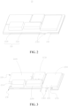
FIG. 2 is a schematic structural diagram of a battery in an electronic device according to a preferred embodiment. -
FIG. 3 is a schematic structural diagram of an electrode assembly and a flexible circuit in the battery shown inFIG. 2 according to an embodiment. -
FIG. 4 is a schematic structural diagram of an electrode assembly and a flexible circuit in the battery shown inFIG. 2 according to another embodiment. -
FIG. 5 is a schematic diagram of distribution of an electrode assembly in the battery shown inFIG. 2 . -
FIG. 6 is a schematic diagram of distribution of a flexible circuit in the battery shown inFIG. 2 . -
FIG. 7 is a schematic diagram of connection between an electrode assembly and a connecting line in the battery shown inFIG. 2 . -
FIG. 8 is a schematic structural diagram of the electrode assembly shown inFIG. 4 and a first enclosure according to an embodiment. -
FIG. 9 is a schematic structural diagram of an electrode assembly in the battery shown inFIG. 2 . -
FIG. 10 is a schematic diagram of a connection structure between the electrode assembly shown inFIG. 9 and a wire portion. -
- 10. Enclosure
- 20. Battery
- 30. Functional device
- 100. Electronic device
- 210. Housing
- 220. Electrode assembly
- 221. Positive plate
- 222. Separator
- 223. Negative plate
- 230. Flexible circuit
- 2110. First enclosure
- 2120. Second enclosure
- 2121. Accommodating groove
- 2122. Non-drawing area
- 2201. Lead-out portion
- 2211. Positive tab
- 2231. Negative tab
- 2210. First electrode assembly
- 2220. Second electrode assembly
- 2230. Third electrode assembly
- 2240. Fourth electrode assembly
- 2250. Fifth electrode assembly
- 2301. Wire portion
- 2302. Connecting portion
- 2303. Output terminal
- 2304. Insulating layer
- 2310. First wire section
- 2320. Second wire section
- 2330. Third wire section
- 2340. Fourth wire section
- The embodiments of the present invention are described in detail below, and the embodiments described with reference to accompanying drawings are exemplary.
- As shown in
FIG. 1 , theelectronic device 100 includes anenclosure 10, abattery 20, and afunctional device 30. Theenclosure 10 is formed with accommodating space, which is configured to accommodate thebattery 20 and thefunctional device 30. - The
functional device 30 is mounted to theenclosure 10 and occupies part of the accommodating space. Thebattery 20 substantially occupies remaining space of the accommodating space. - For example, in some application scenarios, the
electronic device 100 may be a portable device such as a notebook computer and a tablet computer, or may be other smart electronic products, such as a mobile phone and a wearable device. Taking theelectronic device 100 as the notebook computer as an example, theenclosure 10 corresponds to a housing of a host part of the notebook computer, and thefunctional device 30 mainly include a main board, a CPU, a hard disk, a memory, a graphics card, a sound card, a heat sink, and the like. Thebattery 30 is a power supply battery for the notebook computer. - In a practical application, after the CPU, the hard disk, the memory, the graphics card, the sound card, and the heat sink are mounted to one side of the main board, a side facing internal accommodating space of the housing occupies part of the accommodating space. Besides, specifications of the functional device are diversified, and overall dimensions are different. After the assembly is completed, the remaining accommodating space is irregular and uneven in shape due to an influence of concave and convexity of the functional devices and a spacing of an arrangement between the functional devices.
- Generally, the
enclosure 10 may be provided with an independent battery compartment, and the battery compartment is arranged in a regular shape to facilitate design and processing. The battery compartment needs to avoid thefunctional device 30 as a whole, resulting in unavailability of a number of irregular spaces. - Based on the above, in the
electronic device 100 disclosed in the present application, thefunctional device 30 is mounted to theenclosure 10 and occupies part of the accommodating space, and thebattery 20 substantially occupies remaining space of the accommodating space. It should be noted that the "substantially" here means that the foregoing remaining space cannot be strictly occupied due to a factor such as a machining accuracy limitation, an assembly requirement, and an electrical safety requirement. Therefore, thebattery 20 can generally occupy the rest of the accommodating space, and can reflect that thebattery 20 and thefunctional device 30 avoid each other and complement each other in volume to use a volume of the accommodating space as much as possible. - In addition, as shown in
FIG. 2 to FIG. 4 , in order to achieve the above object, thebattery 20 disclosed in the embodiment of the present disclosure includes ahousing 210,multiple electrode assemblies 220, and aflexible circuit 230. - The
multiple electrode assemblies 220 have predetermined overall dimensions and are arranged according to predetermined positions respectively. In a specific implementation, theelectronic device 100 needs to implement a specific function, and thefunctional device 30 may be arranged in theenclosure 10 prior to thebattery 20. Correspondingly, the shape and distribution of the remaining space within theenclosure 10 are also substantially determined. In this way, overall dimensions and positions of themultiple electrode assemblies 220 can be divided in advance according to the shape and distribution of the remaining space. Meanwhile, in order to meet the demand that thebattery 20 can output power to the outside, the series and/or parallel relationship between themultiple electrode assemblies 220 can be preset to set an output current, voltage, and the like. - At least two of the
electrode assemblies 220 have different heights, which can be set according to the volume occupation of thefunctional device 30. In this way, each of theelectrode assemblies 220 may be arranged in a mutual avoidance relationship with the multiplefunctional devices 30 in height. That is to say, when thebattery 20 is placed in the accommodating space, thefunctional device 30 of theelectronic device 100 occupies part of the accommodating space. For thebattery 20, the overall dimension and the position arrangement of theelectrode assemblies 220 is preset according to the arrangement of thefunctional device 30, and theelectrode assemblies 220 is set to a height that matches the corresponding position of thefunctional device 30. For example, at a predetermined position, the height of theelectrode assembly 220 provided corresponding thereto is correspondingly set lower when the height of thefunctional device 30 is higher, and the height of theelectrode assembly 220 provided corresponding thereto is correspondingly set higher when the height of thefunctional device 30 is lower. As a result, thebattery 20 substantially occupies the rest of the accommodating space, and realizes the full utilization of the accommodating space. - During specific implementation, a shape of the
electrode assembly 220 may be a regular shape, so as to be formed by a winding process. For example, in order to reduce the difficulty of processing, theelectrode assembly 220 may be substantially constructed as a rectangular shape. It should be understood that theelectrode assembly 220 can may be set to an irregular shape, that is, a special-shaped shape, such as a diamond, a fan, and a trapezoid. In this context, theelectrode assembly 220 may be molded in a laminated manner. In a practical application, the shape of theelectrode assembly 220 can be set according to a setting requirement of the accommodating space. - The predetermined position of the
electrode assembly 220 is provided with a lead-out portion 2201, so as to realize the series and parallel connection between themultiple electrode assemblies 220. - The predetermined position of the
housing 210 protrudes outward, and multipleaccommodating grooves 2121 are correspondingly formed inside thehousing 210. The multipleaccommodating grooves 2121 match themultiple electrode assemblies 220 in the overall dimensions, so as to correspondingly accommodate themultiple electrode assemblies 220. - The
flexible circuit 230 is integrally formed with thehousing 210 and laid based on a predetermined serial/parallel relationship of themultiple electrode assemblies 220 and a position of the lead-out portion 2201. Theflexible circuit 230 includes anoutput terminal 2303 and multiple connectingportions 2302. The multiple connectingportions 2302 are configured to be connected to the corresponding lead-outportions 2201 to electrically connect themultiple electrode assemblies 220. Theoutput terminal 2303 extends out of thehousing 210 for leading out power. - That the
flexible circuit 230 forms an integral structure with thehousing 210 may be understood as a main part of theflexible circuit 230 is integrally fixed with the inner side of thehousing 210 by processes such as bonding, inlay, welding, and cladding, and theoutput terminal 2303 and the connectingportion 2302 of theflexible circuit 230 may protrude from the inner side of thehousing 210, so as to realize the electrical connection with themultiple electrode assemblies 220 through the connectingportion 2302, and realize the electrical lead-out of thebattery 20 through theoutput terminal 2303. - For example, in a preferred implementation, the
flexible circuit 230 includes awire portion 2301, the connectingportion 2302, and theoutput terminal 2303. Thewire portion 2301 is integrally formed on the inner side of thehousing 210. The multiple connectingportions 2302 and theoutput terminal 2303 are arranged on thewire portion 2301, and each of the connectingportions 2302 protrudes from the inner side of thehousing 210 and extends to the corresponding lead-out portion 2201. - As described above, after the
multiple electrode assemblies 220 are arranged at the predetermined position, in order to meet the demand that thebattery 20 can output power to the outside, the series and/or parallel relationship between themultiple electrode assemblies 220 can be preset to set an output current, voltage, and the like. If a common circuit with a coating film is used to complete the connection of themultiple electrode assemblies 220, the non-foldability of the common circuit weakens the safety performance of the battery. Besides, an overall layout is messy and complicated if the circuit is directly connected inside the battery. Therefore, the present disclosure solves a risk caused by the non-foldability of the common circuit by using the flexible circuit that can be freely bent, wound, and folded. By designing the serial/parallel relationship between theelectrode assemblies 220 in advance in the flexible circuit, positive and negative electrode connecting terminals connected with eachelectrode assembly 220 on theflexible circuit 230 are drawn to theelectrode assembly 220 at the corresponding position, and are connected with positive and negative electrode pins drawn from theelectrode assembly 220 at the corresponding position to realize series or parallel connection between themultiple electrode assemblies 220. - In another preferred implementation, the
housing 210 includes afirst enclosure 2110 and asecond enclosure 2120. - The
first enclosure 2110 is substantially located in a same plane. In other words, thefirst enclosure 2110 is substantially a flat plate-like structure. Thesecond enclosure 2120 is arranged opposite to thefirst enclosure 2110 and defining the accommodating space together with thefirst enclosure 2110. Thesecond enclosure 2120 is recessed at a predetermined position away from thefirst enclosure 2110 to form the multipleaccommodating grooves 2121. - In a practical application, the
housing 210 may be an aluminum-plastic film, and thefirst enclosure 2110 is a relatively flat side of the aluminum-plastic film. Thesecond enclosure 2120 can be drawn deep to form theaccommodating groove 2121 that is recessed at the predetermined position. - During specific implementation, according to the predetermined overall dimensions and the predetermined position arrangement of the
multiple electrode assemblies 220, the aluminum-plastic film can be scoured to a different depth based on a specific position. While theflexible circuit 230 cannot be stamped, so theflexible circuit 230 needs to be designed to a bottom plane film of the aluminum-plastic film without punching, and the connectingportion 2302 corresponding to the position of eachelectrode assembly 220 is reserved. Then, the positive/negative lead-outportions 2201 at each position of theelectrode assembly 230 are electrically connected with the corresponding connectingportions 2302 of theflexible circuit 230, respectively. The connectingportion 2302 of theelectrode assembly 220 is usually formed by centralized spot welding of the tab of each electrode plate. The lead-out portion 2201 and the connectingportion 2302 may be electrically connected by spot welding or riveting to complete the serial/parallel connection between theelectrode assemblies 220 inside thebattery 20. - The
flexible circuit 230 may form an integral structure with thefirst enclosure 2110, or may form an integral structure with thesecond enclosure 2120. - For example, the
flexible circuit 230 may be attached to the inner wall of thefirst enclosure 2110. In another implementation, theflexible circuit 230 may be attached to the inner wall of thesecond enclosure 2120. Since theflexible circuit 230 cannot be scoured and drawn, the flexible circuit needs to be distributed in anon-drawing area 2122 of thesecond enclosure 2120. - The
flexible circuit 230 includes a flexible circuit layer and an insulatinglayer 2304. The flexible circuit layer is attached to the inner wall of thehousing 210. During specific implementation, the flexible circuit layer may include awire portion 2301, the connectingportion 2302, and theoutput terminal 2303. - Taking the
flexible circuit 230 forms an integral structure with thefirst enclosure 2110 as an example, during specific implementation, the positive/negative lead-outportions 2201 at each position of theelectrode assembly 230 may alternatively be arranged close to an inner surface of thefirst enclosure 2110. After the flexible circuit layer is attached to an inner wall of thefirst enclosure 2110, the connectingportion 2302 may be bent by the inner wall of thefirst enclosure 2110 and extend to the positive/negative lead-out portion 2201 at the corresponding position of theelectrode assembly 230. The insulatinglayer 2304 is coated on the outer side of the flexible circuit layer and exposes the connectingportion 2302 and theoutput terminal 2303. In this way, the insulatinglayer 2304 isolates a side of the flexible circuit layer close to theelectrode assembly 220, plays an insulating protection role, and at the same time prevents an electrolyte in the later battery from corroding the line. - In a preferred implementation, the flexible circuit layer includes multiple wire sections, and the multiple wire sections are predetermined based on the predetermined serial/parallel relationship and positions of the lead-
out portion 2201 and theoutput terminal 2303. At least one of the connectingportion 2302 and theoutput terminal 2303 is integrally preformed with one of the wire sections. - As an example, as shown in
FIG. 5 to FIG. 10 , in a specific embodiment, thebattery 20 includes fiveelectrode assemblies 220, which are specifically referred to as afirst electrode assembly 2210, asecond electrode assembly 2220, athird electrode assembly 2230, afourth electrode assembly 2240, and afifth electrode assembly 2250. Theseelectrode assemblies 220 are rectangular in shape, and each electrode assembly has three dimensions: length, width, and height. The width and length are respectively the dimensions of the electrode assembly in two directions perpendicular to the height direction. As described above, at least two of the fiveelectrode assemblies 220 have different heights. During specific implementation, thefunctional devices 30 in theelectronic device 100 have different specifications, therefore, the fiveelectrode assemblies 220 have different heights generally, and at least twoelectrode assemblies 220 have different widths, and/or at least twoelectrode assemblies 220 have different lengths among the fiveelectrode assemblies 220. In this example, the length, width, and height of the first electrode assembly to the fifth electrode assembly are different from each other. The implementation may be set according to a specific requirement. - The
first electrode assembly 2210, thesecond electrode assembly 2220, thethird electrode assembly 2230, thefourth electrode assembly 2240, and thefifth electrode assembly 2250 are arranged in a predetermined form, and a spacing is defined between the adjacent electrode assemblies. The lead-out portion 2201 of eachfifth electrode assembly 220 needs to be connected with theflexible circuit 230, and is arranged toward the spacing accordingly. As shown inFIG. 3 , the positive lead-out portion and the negative lead-out portion of thesecond electrode assembly 2220 are arranged in a spacing between thesecond electrode assembly 2220 and thethird electrode assembly 2230. The positive lead-out portion and the negative lead-out portion of thesecond electrode assembly 2220 are arranged in a spacing between thesecond electrode assembly 2220 and thethird electrode assembly 2230. The positive lead-out portion and the negative lead-out portion of thethird electrode assembly 2230 are arranged in a spacing between thethird electrode assembly 2230 and thefifth electrode assembly 2250. The positive lead-out portion of thefourth electrode assembly 2240 and thefifth electrode assembly 2250 are arranged in a spacing between thefourth electrode assembly 2240 and thefifth electrode assembly 2250. The negative lead-out portion of thefifth electrode assembly 2250 is arranged in a spacing between thefifth electrode assembly 2250 and thefirst electrode assembly 2210. The positive lead-out portion of thefirst electrode assembly 2210, the negative lead-out portion, and the negative lead-out portion of thefourth electrode assembly 2240 are arranged toward an outer peripheral side of the respective electrode assemblies. - Accordingly, in order to achieve a predetermined series-parallel relationship between the first electrode assembly to the fifth electrode assembly, multiple wire sections are arranged on the
wire portion 2301 of theflexible circuit 230. For example, as shown inFIG. 4 , when it is necessary to realize that thefirst electrode assembly 2210 is connected in series with thesecond electrode assembly 2220 and thethird electrode assembly 2230 after being connected in parallel, and then connected in series with thefourth electrode assembly 2240 and thefifth electrode assembly 2250, thewire portion 2301 can be arranged into four sections, that is, afirst wire section 2310, asecond wire section 2320, athird wire section 2330, and afourth wire section 2340. - As shown in
FIG. 7 , thefirst wire section 2310 is connected with the positive lead-out portion of thefirst electrode assembly 2210, and is multiplexed as the positive electrode output terminal of thebattery 20. - One end of the
second wire section 2320 is connected with the negative lead-out portion of thefirst electrode assembly 2210, and the other end separates two connectingportions 2302, which are respectively connected with the positive lead-out portions of thesecond electrode assembly 2220 and thethird electrode assembly 2230. - Both ends of the
third wire section 2330 are each divided into two connectingportions 2302. The two connectingportions 2302 at one end are respectively connected with the negative lead-out portion of thesecond electrode assembly 2220 and the negative lead-out portion of thefifth electrode assembly 2250, the two connectingportions 2302 at the other end are respectively connected with the positive lead-out portion of thefourth electrode assembly 2240 and the positive lead-out portion of thefifth electrode assembly 2250. - One end of the
fourth wire section 2340 is divided into two connectingportions 2320, which are respectively connected with the negative lead-out portion of thefourth electrode assembly 2240 and the negative lead-out portion of thefifth electrode assembly 2250, the other end is multiplexed as the negative output terminal of thebattery 20. - Through the arrangement and the connection of the wire section, the
first electrode assembly 2210, thesecond electrode assembly 2220 and thethird electrode assembly 2230 after being connected in parallel, and the series connection of thefourth electrode assembly 2240 and thefifth electrode assembly 2250 after being connected in parallel can be realized, and the positive output and the negative output of thebattery 20 may be realized at the same time. - The insulating
layer 2304 covers the multiple wire sections. For example, in a preferred implementation, the insulatinglayer 2304 is formed by coating an insulating material on a surface of the wire section. In another preferred implementation, the insulatinglayer 2304 is an insulating film, and the insulating film is attached to an outer side of the flexible circuit layer 2312 and combined with thehousing 210. During specific implementation, as shown inFIG. 8 to FIG. 10 , thehousing 210 may be an aluminum-plastic film, and the flexible circuit layer and the insulatinglayer 2304 may alternatively be designed into the aluminum-plastic film in advance. The tab is extracted by embedding a flexible circuit layer and an insulatinglayer 2304 with corrosion resistance and insulation in advance in anoriginal nylon layer 2111, anAl layer 2112, and aPP layer 2113 of the aluminum-plastic film, and drawing the positive and negative tabs are through the positive and negative tab pins. - The
electrode assembly 220 is the electrode core, and includes apositive plate 221, aseparator 222, and anegative plate 223. For example, in a preferred implementation, theelectrode assembly 220 includes multiple includes multiplepositive plates 221,multiple separators 222, and multiplenegative plates 223 that are arranged in a stack. Apositive tab 2211 is arranged on thepositive plate 221, and anegative tab 2231 is arranged on thenegative plate 223. - The multiple
positive tabs 2211 of eachelectrode assembly 220 are connected together to form a positive lead-out portion, and the multiplenegative tabs 2231 are connected together to form a negative lead-out portion. - The connecting
portion 2302 protrudes from theflexible circuit 230 and extends to a position docked with the corresponding positive lead-out portion or the negative lead-out portion, so as to form an electrical connection with the corresponding positive lead-out portion or the negative lead-out portion. - In the
battery 20 and theelectronic device 100 using thebattery 20, thefunctional device 30 of theelectronic device 100 and the shape of thebattery 20 engage with each other, theelectrode assembly 220 and the correspondingfunctional device 30 form a mutual avoidance and complementary relationship in occupation of the space, so as to make full use of the accommodating space. In addition, theflexible circuit 230 is integrally formed on the inner side of theenclosure 210 due to the convenient molding and layout, so that the circuit design of thebattery 20 can be simplified, and the design and layout of thebattery 20 can be simplified. In this way, the utilization rate of the internal space of theelectronic device 100 can be improved, and the thinness and lightness of theelectronic device 100 can be easily realized. - The
flexible circuit 230 is accommodated in the housing and laid based on a predetermined serial/parallel relationship of themultiple electrode assemblies 220 and a position of the lead-out portion 2201 to electrically connect the multiple electrode assemblies. Wires are arranged in thehousing 210 of thebattery 20, and the electrical connection of theelectrode assembly 220 is realized. The output terminal extends out of the housing for electrical lead-out, which can simplify an external circuit and reduce occupation of an internal space of theelectronic device 100 by an external circuit and a component. - In a preferred implementation, the flexible circuit further includes a
wire portion 2301 and multiple connectingportions 2302 arranged on thewire portion 2301. Thewire portion 2301 is laid on a circumferential side of theelectrode assembly 220 based on the predetermined serial/parallel relationship of themultiple electrode assemblies 220 and the position of the lead-out portion 2201. The multiple connectingportions 2302 are arranged on thewire portion 2301 and electrically connected with the lead-out portion 2201 at a corresponding position. Theoutput terminal 2303 is arranged on thewire portion 2301. - During specific implementation, the
electrode assembly 220 may be made by winding a positive plate, a separator, and a negative plate. A tab is reserved on the positive plate and the negative plate. Accordingly, the lead-out portion 2201 may correspondingly include a positive lead-out portion and a negative lead-out portion that are formed after the winding by respectively soldering the positive tabs together and soldering the negative tabs together. The lead-out portion 2201 may be arranged on a side surface of theelectrode assembly 220, and the lead-out portion 2201 of themultiple electrode assemblies 220 may be substantially arranged on a same plane, to facilitate arrangement of theflexible circuit 230. - The
wire portion 2301 may include multiple wire sections predetermined based on the predetermined serial/parallel relationship and the position of the lead-out portion. Since themultiple electrode assemblies 220 are different in size and specification to meet the requirements of space occupation, in order to meet the requirement for output power, the electrode cores need to be connected according to the predetermined series and parallel relationship. Thewire portion 2301 is preset as multiple wire sections, which can more conveniently complete the predetermined serial/parallel connection, especially the series connection, according to the arrangement of theelectrode assembly 220. - To facilitate processing and molding, and to simplify the connection step, at least one of the connecting
portion 2302 and theoutput terminal 2303 may be integrally preformed with one of the wire sections. During specific implementation, the connectingportion 2302 can be integrally formed with the corresponding wire section, and the connectingportion 2302 is located at a terminal of the corresponding wire section. Theoutput terminal 2303 includes a positive output terminal and a negative output terminal, one of which is integrally formed with a wire section, and the other may be formed by a wire section. An outer side of the wire portion is covered with an insulatingfilm 240, to achieve an electrical insulation protection. Apart of the connectingportion 2302 and theoutput terminal 2303 are exposed to facilitate electrical connection. - A spacing may be defined between
adjacent electrode assemblies 220 as setting the arrangement of themultiple electrode assemblies 220. The lead-out portion 2201 of eachfifth electrode assembly 220 needs to be connected with theflexible circuit 230, and is arranged toward the spacing accordingly. A part of thewire portion 2301 located betweenadjacent electrode assemblies 220 is embedded in a corresponding spacing. In this arrangement, the electrical connection between theflexible circuit 230 and the lead-out portion 2201 of theelectrode assembly 220 is facilitated. Besides, the lead-out portion 2201 of theelectrode assembly 220 needs to occupy part of the space, therefore, thewire portion 2301 of theflexible circuit 230 is embedded in the spacing that needs to be reserved, which is equivalent to multiplexing this part of the space. As a result, the space utilization rate is improved and the wiring is facilitated. - During specific implementation, the
housing 210 may include afirst enclosure 2110 and asecond enclosure 2120. - The
first enclosure 2110 is substantially located in the same plane, that is, thefirst enclosure 2110 is substantially a flat film, forming a flat side of thehousing 210. During specific implementation, the "substantially" here can be used for a tolerance and an error caused by an impact of machining accuracy, or a local special shape introduced due to a local design requirement, and the like. In all, thefirst enclosure 2110 is generally flat. - The
second enclosure 2120 is recessed at a predetermined position away from thefirst enclosure 2110 to form the multipleaccommodating grooves 2121. A shape of eachaccommodating groove 2121 matches the correspondingelectrode assembly 220. - Peripheral sides of the
first enclosure 2110 and thesecond enclosure 2120 are respectively provided an edge sealing portion. The peripheral sides of thefirst enclosure 2110 and thesecond enclosure 2120 is sealed and connected through the edge sealing portion, so that theelectrode assembly 220 and theflexible circuit 230 are packaged in theenclosure 210. An outer side of theoutput terminal 2303 is covered with a sealing adhesive layer (not shown in the figure). Theoutput terminal 2303 extends out of thehousing 210 between the two edge sealing portions; and theoutput terminal 2303 is sealed and connected with a corresponding position of the edge sealing portion through the sealing adhesive layer for leading out power of thebattery 20. - The lead-
out portion 2201 of theelectrode assembly 220 and theflexible circuit 230 are arranged close to thefirst enclosure 2110. Neat wiring can be formed by using the flatfirst enclosure 2110, and late stress deformation can be avoided as much as possible. - In the description of this specification, the description of the reference terms such as "an embodiment", "some embodiments", "exemplary embodiments", "example", "specific example", or "some examples" means that the specific features, structures, materials, or characteristics described with reference to the embodiment or example are included in at least one embodiment or example of the present disclosure. In the present disclosure, exemplary descriptions of the foregoing terms do not necessarily refer to the same embodiment or example.
- Although the embodiments of the present disclosure have been shown and described, a person of ordinary skill in the art should understand that various changes, modifications, replacements, and variations may be made to the embodiments without departing from the principles and spirit of the present disclosure, and the scope of the present disclosure is as defined by the appended claims and their equivalents.
Claims (10)
- A battery, applicable to an electronic device, wherein the electronic device comprises an enclosure having an accommodating space formed therein and a plurality of functional devices; the plurality of functional devices are accommodated in the enclosure and occupy part of the accommodating space of the enclosure; and the battery comprising:a plurality of electrode assemblies, respectively arranged in a predetermined size specification and arranged at predetermined positions to substantially occupy the rest of the accommodating space, wherein each of the predetermined positions of the electrode assemblies is provided with a lead-out portion;a housing, having a predetermined position protruding outward and forming inside a plurality of accommodating grooves correspondingly; and the plurality of accommodating grooves matching the overall dimensions of the plurality of electrode assemblies to correspondingly accommodate the plurality of electrode assemblies; anda flexible circuit, integrally formed with the housing and laid based on a predetermined serial/parallel relationship of the plurality of electrode assemblies and a position of the lead-out portion, the flexible circuit comprising an output terminal and a plurality of connecting portions; the plurality of connecting portions being configured to be connected with the corresponding lead-out portions to electrically connect the plurality of electrode assemblies; and the output terminal extending out of the housing for leading out power.
- The battery according to claim 1, wherein the flexible circuit further comprises a wire portion; the wire section is integrally formed on an inner side of the housing;
the plurality of connecting portions and the output terminal are arranged on the wire portion; and the connecting portions protrude from an inner side of the enclosure and extend to the corresponding lead-out portions. - The battery according to claim 1 or 2, wherein the housing comprises:a first enclosure, substantially located on a same plane; anda second enclosure, arranged opposite to the first enclosure and defining the accommodating space together with the first enclosure, wherein the predetermined position of the second enclosure is recessed away from the first enclosure to form the plurality of accommodating grooves; andthe flexible circuit is attached to an inner wall of the first enclosure.
- The battery according to any of claims 1 to 3, wherein the housing comprises:a first enclosure, substantially located on a same plane; anda second enclosure, arranged opposite to the first enclosure and defining the accommodating space together with the first enclosure, wherein the predetermined position of the second enclosure is recessed away from the first enclosure to form the plurality of accommodating grooves; andthe flexible circuit is attached to an inner wall of the second enclosure and arranged in a non-drawing area of the second enclosure.
- The battery according to any of claims 1 to 4, wherein the flexible circuit comprises:a flexible circuit layer, attached to an inner wall of the housing and comprising the wire portion, the connecting portion, and the output terminal; andan insulating layer, covering an outer side of the flexible circuit layer and exposing the connecting portion and the output terminal.
- The battery according to claim 5, wherein the flexible circuit layer comprises a plurality of wire sections; the plurality of wire sections are predetermined based on the predetermined serial/parallel relationship and positions of the lead-out portion and the output terminal;at least one of the connecting portion and the output terminal is integrally preformed with one of the wire sections; andthe insulating layer covers the plurality of wire sections.
- The battery according to claim 6, wherein the insulating layer is formed by coating an insulating material on a surface of the wire section.
- The battery according to claim 7, wherein each of the electrode assemblies comprises a plurality of positive plates, a plurality of separators, and a plurality of negative plates that are arranged in a stack; each of the positive plates is provided with a positive tab; each of the negative plates is provided with a negative tab;a plurality of positive tabs of each electrode assembly are connected together to form a positive lead-out portion; a plurality of negative tabs are connected together to form a negative lead-out portion; andthe connecting portion protrudes from the wire section and extends to a position docked with the corresponding positive lead-out portion or the negative lead-out portion.
- The battery according to any of claims 6 to 8, wherein the insulating layer is an insulating film; and the insulating film is attached to the outer side of the flexible circuit layer and engaged with the housing.
- An electronic device, comprisingan enclosure, having an accommodating space formed therein; anda plurality of functional devices, mounted to the enclosure and occupying part of the accommodating space,wherein the electronic device further comprises the battery according to any of claims 1 to 9; andthe battery substantially occupies the rest of the accommodating space.
Applications Claiming Priority (2)
| Application Number | Priority Date | Filing Date | Title |
|---|---|---|---|
| CN202110340406.4A CN115149172A (en) | 2021-03-30 | 2021-03-30 | Batteries and electronic equipment using the same |
| PCT/CN2022/074404 WO2022206162A1 (en) | 2021-03-30 | 2022-01-27 | Battery and electronic apparatus using said battery |
Publications (2)
| Publication Number | Publication Date |
|---|---|
| EP4254624A1 true EP4254624A1 (en) | 2023-10-04 |
| EP4254624A4 EP4254624A4 (en) | 2024-12-04 |
Family
ID=83403768
Family Applications (1)
| Application Number | Title | Priority Date | Filing Date |
|---|---|---|---|
| EP22778350.3A Pending EP4254624A4 (en) | 2021-03-30 | 2022-01-27 | BATTERY AND ELECTRONIC DEVICE USING SAID BATTERY |
Country Status (6)
| Country | Link |
|---|---|
| US (1) | US20230344066A1 (en) |
| EP (1) | EP4254624A4 (en) |
| JP (1) | JP7660204B2 (en) |
| KR (1) | KR20230113794A (en) |
| CN (1) | CN115149172A (en) |
| WO (1) | WO2022206162A1 (en) |
Family Cites Families (15)
| Publication number | Priority date | Publication date | Assignee | Title |
|---|---|---|---|---|
| KR100614375B1 (en) * | 2005-04-11 | 2006-08-22 | 삼성에스디아이 주식회사 | Collapsible Pouch Type Battery |
| JP5011678B2 (en) * | 2005-08-12 | 2012-08-29 | ソニー株式会社 | Secondary battery |
| US9331358B2 (en) * | 2010-01-26 | 2016-05-03 | Apple Inc. | Battery with multiple jelly rolls in a single pouch |
| US9040187B2 (en) | 2010-07-13 | 2015-05-26 | Apple, Inc. | Battery pack with cells of different capacities electrically coupled in parallel |
| US20130089755A1 (en) | 2011-10-11 | 2013-04-11 | In-Soo Park | Battery Pack |
| US9735443B2 (en) * | 2012-04-17 | 2017-08-15 | Semiconductor Energy Laboratory Co., Ltd. | Power storage device and method for manufacturing the same |
| DE102014217119A1 (en) * | 2014-08-28 | 2016-03-03 | Robert Bosch Gmbh | Cell carrier and cell connector for battery cells and battery module, battery, battery system, vehicle and method for producing a battery module |
| KR101479607B1 (en) * | 2014-08-29 | 2015-01-06 | 엔블록셀유한책임회사 | An enbloc clip shaped lithium secondary battery pack with flexible connection among the cells |
| WO2016085020A1 (en) * | 2014-11-25 | 2016-06-02 | 엘지전자 주식회사 | Portable display device |
| US20160241048A1 (en) * | 2015-02-18 | 2016-08-18 | Microsoft Technology Licensing, Llc | Battery Assembly Combining Multiple Different Batteries |
| JP6487712B2 (en) * | 2015-02-23 | 2019-03-20 | 昭和電工パッケージング株式会社 | Power storage device |
| US20170092994A1 (en) | 2015-09-25 | 2017-03-30 | Intel Corporation | Smart battery with integrated sensing and electronics |
| JP6753513B2 (en) | 2017-03-06 | 2020-09-09 | 株式会社村田製作所 | Rechargeable battery |
| JP7054892B2 (en) * | 2017-09-19 | 2022-04-15 | エリーパワー株式会社 | Assembled battery and manufacturing method of assembled battery |
| KR102695030B1 (en) * | 2018-12-17 | 2024-08-13 | 삼성전자 주식회사 | Foldable battery and electronic device including the same |
-
2021
- 2021-03-30 CN CN202110340406.4A patent/CN115149172A/en active Pending
-
2022
- 2022-01-27 KR KR1020237022127A patent/KR20230113794A/en active Pending
- 2022-01-27 WO PCT/CN2022/074404 patent/WO2022206162A1/en not_active Ceased
- 2022-01-27 EP EP22778350.3A patent/EP4254624A4/en active Pending
- 2022-01-27 JP JP2023540642A patent/JP7660204B2/en active Active
-
2023
- 2023-06-27 US US18/215,008 patent/US20230344066A1/en active Pending
Also Published As
| Publication number | Publication date |
|---|---|
| JP7660204B2 (en) | 2025-04-10 |
| JP2024509032A (en) | 2024-02-29 |
| EP4254624A4 (en) | 2024-12-04 |
| KR20230113794A (en) | 2023-08-01 |
| US20230344066A1 (en) | 2023-10-26 |
| CN115149172A (en) | 2022-10-04 |
| WO2022206162A1 (en) | 2022-10-06 |
Similar Documents
| Publication | Publication Date | Title |
|---|---|---|
| CN110021716A (en) | Battery unit, battery modules and automobile | |
| CN105122494A (en) | Battery cells with rounded corners | |
| CN104247094A (en) | Battery cell with irregular structure and battery module using the battery cell | |
| WO2014137017A1 (en) | Electrode assembly having rounded corners | |
| CN218632377U (en) | Battery and electronic device | |
| JP4020579B2 (en) | Battery block, battery pack and battery pack fixing structure | |
| WO2024140498A1 (en) | Electrochemical apparatus and electrical device | |
| JP2010277692A (en) | Pack battery and pack battery intermediate | |
| JP7607771B2 (en) | Electronics | |
| CN210668435U (en) | Batteries and Electronic Equipment | |
| EP4254624A1 (en) | Battery and electronic apparatus using said battery | |
| JP7048851B2 (en) | Battery module for powering emergency phones | |
| EP4258438A1 (en) | Battery and electronic device using same | |
| KR101763265B1 (en) | Battery Cell Comprising Battery Case with Trimming Part Corresponding to Electorde Assembly of Stair-like Structure | |
| CN112103470A (en) | Secondary battery and battery module | |
| KR102591513B1 (en) | Battery Pack | |
| JP2009104843A (en) | Insulator structure for battery pack and battery pack structure | |
| CN213988978U (en) | Quick heat radiation structure of cell-phone lithium cell | |
| KR20140109280A (en) | Battery Cell Having Electrode Assembly of Stair-like Structure | |
| WO2023230900A1 (en) | Battery and electric device | |
| CN116896824B (en) | Battery protection plate module, method and device, battery module and electronic equipment | |
| CN223181836U (en) | mobile power bank | |
| CN224138155U (en) | A secondary battery and electronic device | |
| CN224190989U (en) | Electrochemical device and electric equipment | |
| CN221126193U (en) | Battery and terminal equipment having the same |
Legal Events
| Date | Code | Title | Description |
|---|---|---|---|
| STAA | Information on the status of an ep patent application or granted ep patent |
Free format text: STATUS: THE INTERNATIONAL PUBLICATION HAS BEEN MADE |
|
| PUAI | Public reference made under article 153(3) epc to a published international application that has entered the european phase |
Free format text: ORIGINAL CODE: 0009012 |
|
| STAA | Information on the status of an ep patent application or granted ep patent |
Free format text: STATUS: REQUEST FOR EXAMINATION WAS MADE |
|
| 17P | Request for examination filed |
Effective date: 20230629 |
|
| AK | Designated contracting states |
Kind code of ref document: A1 Designated state(s): AL AT BE BG CH CY CZ DE DK EE ES FI FR GB GR HR HU IE IS IT LI LT LU LV MC MK MT NL NO PL PT RO RS SE SI SK SM TR |
|
| DAV | Request for validation of the european patent (deleted) | ||
| DAX | Request for extension of the european patent (deleted) | ||
| A4 | Supplementary search report drawn up and despatched |
Effective date: 20241105 |
|
| RIC1 | Information provided on ipc code assigned before grant |
Ipc: H01M 50/289 20210101ALI20241029BHEP Ipc: H01M 50/284 20210101ALI20241029BHEP Ipc: H01M 50/244 20210101ALI20241029BHEP Ipc: G06F 1/16 20060101ALI20241029BHEP Ipc: H01M 10/04 20060101ALI20241029BHEP Ipc: H01M 50/204 20210101AFI20241029BHEP |